EP3342597A1 - Print media transport apparatus - Google Patents
Print media transport apparatus Download PDFInfo
- Publication number
- EP3342597A1 EP3342597A1 EP18154103.8A EP18154103A EP3342597A1 EP 3342597 A1 EP3342597 A1 EP 3342597A1 EP 18154103 A EP18154103 A EP 18154103A EP 3342597 A1 EP3342597 A1 EP 3342597A1
- Authority
- EP
- European Patent Office
- Prior art keywords
- pallet
- zone
- track
- pallets
- descending
- Prior art date
- Legal status (The legal status is an assumption and is not a legal conclusion. Google has not performed a legal analysis and makes no representation as to the accuracy of the status listed.)
- Granted
Links
Images


Classifications
-
- B—PERFORMING OPERATIONS; TRANSPORTING
- B41—PRINTING; LINING MACHINES; TYPEWRITERS; STAMPS
- B41J—TYPEWRITERS; SELECTIVE PRINTING MECHANISMS, i.e. MECHANISMS PRINTING OTHERWISE THAN FROM A FORME; CORRECTION OF TYPOGRAPHICAL ERRORS
- B41J13/00—Devices or arrangements of selective printing mechanisms, e.g. ink-jet printers or thermal printers, specially adapted for supporting or handling copy material in short lengths, e.g. sheets
- B41J13/10—Sheet holders, retainers, movable guides, or stationary guides
-
- B—PERFORMING OPERATIONS; TRANSPORTING
- B65—CONVEYING; PACKING; STORING; HANDLING THIN OR FILAMENTARY MATERIAL
- B65H—HANDLING THIN OR FILAMENTARY MATERIAL, e.g. SHEETS, WEBS, CABLES
- B65H7/00—Controlling article feeding, separating, pile-advancing, or associated apparatus, to take account of incorrect feeding, absence of articles, or presence of faulty articles
- B65H7/20—Controlling associated apparatus
-
- B—PERFORMING OPERATIONS; TRANSPORTING
- B41—PRINTING; LINING MACHINES; TYPEWRITERS; STAMPS
- B41J—TYPEWRITERS; SELECTIVE PRINTING MECHANISMS, i.e. MECHANISMS PRINTING OTHERWISE THAN FROM A FORME; CORRECTION OF TYPOGRAPHICAL ERRORS
- B41J11/00—Devices or arrangements of selective printing mechanisms, e.g. ink-jet printers or thermal printers, for supporting or handling copy material in sheet or web form
- B41J11/02—Platens
- B41J11/06—Flat page-size platens or smaller flat platens having a greater size than line-size platens
-
- B—PERFORMING OPERATIONS; TRANSPORTING
- B41—PRINTING; LINING MACHINES; TYPEWRITERS; STAMPS
- B41J—TYPEWRITERS; SELECTIVE PRINTING MECHANISMS, i.e. MECHANISMS PRINTING OTHERWISE THAN FROM A FORME; CORRECTION OF TYPOGRAPHICAL ERRORS
- B41J13/00—Devices or arrangements of selective printing mechanisms, e.g. ink-jet printers or thermal printers, specially adapted for supporting or handling copy material in short lengths, e.g. sheets
- B41J13/0009—Devices or arrangements of selective printing mechanisms, e.g. ink-jet printers or thermal printers, specially adapted for supporting or handling copy material in short lengths, e.g. sheets control of the transport of the copy material
-
- B—PERFORMING OPERATIONS; TRANSPORTING
- B65—CONVEYING; PACKING; STORING; HANDLING THIN OR FILAMENTARY MATERIAL
- B65H—HANDLING THIN OR FILAMENTARY MATERIAL, e.g. SHEETS, WEBS, CABLES
- B65H5/00—Feeding articles separated from piles; Feeding articles to machines
- B65H5/04—Feeding articles separated from piles; Feeding articles to machines by movable tables or carriages
-
- B—PERFORMING OPERATIONS; TRANSPORTING
- B65—CONVEYING; PACKING; STORING; HANDLING THIN OR FILAMENTARY MATERIAL
- B65H—HANDLING THIN OR FILAMENTARY MATERIAL, e.g. SHEETS, WEBS, CABLES
- B65H2405/00—Parts for holding the handled material
- B65H2405/30—Other features of supports for sheets
- B65H2405/35—Means for moving support
- B65H2405/352—Means for moving support in closed loop
-
- B—PERFORMING OPERATIONS; TRANSPORTING
- B65—CONVEYING; PACKING; STORING; HANDLING THIN OR FILAMENTARY MATERIAL
- B65H—HANDLING THIN OR FILAMENTARY MATERIAL, e.g. SHEETS, WEBS, CABLES
- B65H2405/00—Parts for holding the handled material
- B65H2405/30—Other features of supports for sheets
- B65H2405/35—Means for moving support
- B65H2405/352—Means for moving support in closed loop
- B65H2405/3521—Means for moving support in closed loop rail guided means, e.g. without permanent interconnection
-
- B—PERFORMING OPERATIONS; TRANSPORTING
- B65—CONVEYING; PACKING; STORING; HANDLING THIN OR FILAMENTARY MATERIAL
- B65H—HANDLING THIN OR FILAMENTARY MATERIAL, e.g. SHEETS, WEBS, CABLES
- B65H2405/00—Parts for holding the handled material
- B65H2405/30—Other features of supports for sheets
- B65H2405/36—Multiple support
-
- B—PERFORMING OPERATIONS; TRANSPORTING
- B65—CONVEYING; PACKING; STORING; HANDLING THIN OR FILAMENTARY MATERIAL
- B65H—HANDLING THIN OR FILAMENTARY MATERIAL, e.g. SHEETS, WEBS, CABLES
- B65H2555/00—Actuating means
- B65H2555/10—Actuating means linear
- B65H2555/13—Actuating means linear magnetic, e.g. induction motors
-
- B—PERFORMING OPERATIONS; TRANSPORTING
- B65—CONVEYING; PACKING; STORING; HANDLING THIN OR FILAMENTARY MATERIAL
- B65H—HANDLING THIN OR FILAMENTARY MATERIAL, e.g. SHEETS, WEBS, CABLES
- B65H2801/00—Application field
- B65H2801/03—Image reproduction devices
-
- B—PERFORMING OPERATIONS; TRANSPORTING
- B65—CONVEYING; PACKING; STORING; HANDLING THIN OR FILAMENTARY MATERIAL
- B65H—HANDLING THIN OR FILAMENTARY MATERIAL, e.g. SHEETS, WEBS, CABLES
- B65H2801/00—Application field
- B65H2801/03—Image reproduction devices
- B65H2801/15—Digital printing machines
Definitions
- print media transport apparatus such as belt-type conveyors or pallets on an endless track are used to convey media on to which text or an image may be printed.
- print media transport apparatus may be used to convey media from a media storage area to a position in which it can be printed (for example, near a printhead of the printer or the like) and then to convey the media to a collection area.
- Figure 1 shows a block diagram of an example of a print media transport apparatus 100 comprising a plurality of pallets 102 which, as will be described in greater detail in relation to the example of Figure 2 below, each have a self-propulsion mechanism, and are to support print media, i.e. a substrate to which a printed image, text or the like may be applied.
- print media may for example comprise a sheet material, such as paper, card stock, plastics, and the like, and may be rigid, substantially rigid or flexible.
- the pallets 102 circulate on an endless track 104.
- the track 104 comprises a printing zone 106, a descending zone 108 and an ascending zone 110.
- the pallets 102 circulate in a clockwise direction and the track 104 is substantially ovoid having a substantially horizontal printing zone 106 and a substantially horizontal return zone linking the descending zone 108 and the ascending zone 110.
- other (for example more convoluted) tracks may be provided.
- inks, toners and the like may be applied to media supported by one or several pallets 102 by an associated printer (not shown).
- pallets 102 on the printing zone 106 are controlled such that at least two pallets 102 move as a group across the printing zone 106 of the track 104 when supporting print media.
- Pallets 102 travelling on the printing zone 106 may thereby form a virtual table on which media is supported and carried relative to a printing mechanism of an associated printer.
- the printing mechanism may for example be associated with an ink supply and comprise a printhead mounted on a moveable carriage, an array of static printheads or the like.
- the printhead(s) may eject drops of ink through orifices or nozzles and towards a print media so as to print onto the media.
- the apparatus 100 further comprises a controller 112 to control the self-propulsion mechanisms of the pallets 102, such that a pallet 102 on the descending zone 108 is at least partially supported by another pallet 102 which is ahead on the track 104, and a pallet 102 on the ascending zone 110 is at least partially driven by pallet 102 which follows on the track 104.
- the controller 112 may comprise processing apparatus, such as a computer or the like, and may execute machine readable instructions in order to control the movement of the pallets 102.
- the controller 112 is shown as part of the apparatus 100.
- the controller 112 may be mounted on a pallet 102 (or the functions thereof may be distributed over several pallets 102), or the controller 112 may be separate, even remote, from the belt 104.
- Figure 2 shows an example of a pallet 102.
- the pallet 102 comprises a frame 202 and self-propulsion mechanism which comprises two linear motors 204 and control circuitry 208, which comprises motor drivers and some processing circuitry.
- the pallet 102 further comprises bearings 206 which are intended to run along the track 104 (which in this example comprises two spaced rails, which may be shaped so as to retain the bearings 206) supported by the frame 202 and driven by the motors 204.
- other propulsion mechanisms such as magnetic mechanisms or the like
- the motor 204 is powered using power collected by brushes 210, which interact with a power supply loop (not shown).
- the power may be provided in another manner, such as by a battery mounted on the pallet 102 or the like.
- the motors 204 are controlled by the control circuitry 208, itself controlled by the controller 112 of the print media transport apparatus 100.
- processing apparatus within the control circuitry 208 and the controller 112 communicate wirelessly. Such communication may comprise commands such as start and stop commands, requests for status updates, and the like.
- the status updates may for example to be to provide feedback to control loops and readings acquired by any sensors (for example hall effect sensors) mounted on a pallet 102.
- control circuitry 208 and the controller 112 act to control the motion of the pallets 102 such that, while a pallet 102 is on the printing zone 106, the motion (e.g. speed and/or location) is controlled to within a tolerance band.
- This may be a relatively tight tolerance band as accurate motion allows for predictable application of inks, toners and the like to media supported by the pallets 102.
- the location of a pallet 102 is controlled to within 10 microns while on the printing zone 106 of the track 104. This may be, for example, to ensure that the pallet 102 places media at an appropriate location for a drop of ink or the like to land, based on the time at which the drop is emitted.
- the pallets 102 are individually controlled while a pallet is on the printing zone 106 in a precision mode. However, outside this zone 106, for example while a pallet 102 is on the descending or ascending zones 108, 110, the motion may be allowed to vary outside the tolerance band.
- Figure 3 shows an example in which two pallets 300 are coupled together.
- the pallets 300 comprise two bar-like portions 302, the portions 302 being coupled in a substantially parallel configuration, the coupling allowing relative rotation between the portions 302.
- the pallets 300 are coupled to one another with a coupling allowing a variable spacing between the pallets 300.
- a slotted coupling 304 (for example, a metal coupling) connects pegs 306 provided on each pallet 300.
- the pegs 306 of the pallets 300 can be separated by the length of the slot in the slotted coupling 304, or the pallets 300 can move closer to one another until they are touching.
- the slotted coupling 304 also allows the pallets 300 to rotate relative to one another as they round the turns in the track 104.
- One of the portions 302 comprises a self-propulsion mechanism 308, the other being driven by the portion 302 having a self-propulsion mechanism 308.
- Such pallets 300 may be joined in an endless loop.
- the self-propulsion mechanisms of the pallets 102, 300 may be controlled by the controller 112 such that, while pallets 102, 300 are on the printing zone 106 of the track 104, the spacing remains constant (which allows for accurate media placement within the printing zone) and, while a pallet 102, 300 is on the descending 108 and ascending 110 zones of the track 104, the spacing is at a minimum (i.e. the pallets 102, 300 are tightly packed and are acting directly on one another).
- the pallets 102,300 may also be tightly packed while on the substantially horizontal return zone of the track 104 such that the pallets 102, 300 on the descending zone 108 can act on the pallets 102, 300 on the ascending zone 110 (and vice versa) indirectly, the ascending pallets 102, 300 acting as a counterbalance to the descending pallets 102, 300, as further explained below.
- Control of the pallets 102, 300 may be carried out as shown in the flow chart of Figure 4 .
- a pallet 102, 300 is on the printing zone 106 of the track 104, it is driven with a first driving force provided by a self-propulsion mechanism of the pallet 102, 300 (block 402).
- a retarding force is applied by at least one other pallet 102, 300 on the track 104 (bock 404).
- a second driving force is provided by at least one other pallet 102, 300 on the track 104 (block 406). This second driving force may be provided gravity acting on at least one pallet 102, 300 on the descending zone 108 of the track 104.
- the retarding force and/or the second driving force may be transmitted via at least one intermediate pallet 102, 300 between the pallet 102, 300 on the ascending zone 110 of the track 104 and the pallet 102, 300 on the descending zone 108 of the track 104 (i.e. via at least one intermediate pallet 102, 300 on the substantially horizontal return zone of the track 104).
- FIGs 5a and 5b compare the current delivered to a self-propulsion mechanism according to two schemes for driving a pallet 102, 300.
- each pallet 102, 300 is driven by its self-propulsion mechanism in isolation.
- the current shows a peak as the pallet 102, 300 is driven to climb and overcome gravity.
- the current shows a dip as gravity is resisted.
- Figure 5b shows the current delivered to drive a pallet 102, 300 according to examples of the methods set out herein, for example according to the flow chart of Figure 4 .
- the current variability is much lower- the average current being supplied in each zone 106, 108, 110 is more similar, in particular in the ascending 108 and descending 110 zones, being substantially constant, or equal between zones.
- the current (and power) supplied to a self-propulsion mechanism of an individual pallet 102, 300 on the ascending zone 110 of track 104 is insufficient to allow that pallet 102, 300 to climb the ascending zone 110 of track 104 (an additional driving force supplied by the action of a descending pallet 102, 300 is employed).
- the method of Figure 4 may be achieved by supplying power or current to the propulsion mechanism of each pallet 102, 300 at a substantially constant average level for all zones of the track 104.
- the actual variability of the current will dependent on factors such as the friction encountered in an apparatus. However, in some examples, the current may be within a range of 50% of the average current.
- the average current supplied while a pallet traverses a particular zone is substantially equal for all zones (or at least for the ascending and descending zones 108, 110). Effectively, ascending pallets 102, 300 will be pushed by following pallets 102, 300 and descending pallets 102, 300 will lean on preceding pallets 102, 300, which therefore provide a retarding force (or counterweight). This balances the driving currents across the phases of motion around the track 104.
- a first, second and third pallet 102, 300 are provided on an endless track 104 of a print media transport apparatus 100.
- the first pallet 102, 300 precedes the second pallet 102, 300 and the second pallet 102, 300 precedes the third pallet 102, 300.
- a self-propulsion mechanism of each of the first, second and third pallet 102, 300 is controlled such that, on a descending zone 108 of the track 104, the first pallet 102, 300 at least partially supports the second pallet 102, 300 and on an ascending zone 110 of the track 104, the third pallet 102, 300 at least partially drives the second pallet 102, 300.
- the pallet movements may be accurately controlled while a pallet 102, 300 is on the printing zone 106 of the track 104, this may be less of a concern in other zones of the track 104.
- Examples in the present disclosure can be provided as methods, systems or machine readable instructions, such as any combination of software, hardware, firmware or the like, which may for example be executed by the controller 112 or the control circuitry 208.
- Such machine readable instructions may be included on a computer readable storage medium (including but is not limited to disc storage, CD-ROM, optical storage, etc.) having computer readable program codes therein or thereon.
- the machine readable instructions may, for example, be executed by a general purpose computer, a special purpose computer, an embedded processor or processors of other programmable data processing devices to realize the functions of the controller 112 and/or control circuitry 208 described in the description and diagrams.
- a processor or processing apparatus may execute the machine readable instructions.
- modules of the apparatus and devices may be implemented by a processor executing machine readable instructions stored in a memory, or a processor operating in accordance with instructions embedded in logic circuitry.
- the term 'processor' is to be interpreted broadly to include a CPU, processing unit, ASIC, logic unit, or programmable gate array etc.
- the methods and functional modules may all be performed by a single processor or divided amongst several processors.
- teachings herein may be implemented in the form of a computer software product, the computer software product being stored in a storage medium and comprising a plurality of instructions for making a computer device implement the methods recited in the examples of the present disclosure.
- the invention may be described by any of the following numbered statements.
- a print media transport apparatus comprising: a plurality of pallets having a self-propulsion mechanism, and being to support print media; an endless track on which the plurality of pallets circulate, the track comprising a printing zone, a descending zone and an ascending zone, a controller to control the self-propulsion mechanisms of the pallets such that a pallet on the descending zone is at least partially supported by another pallet which is ahead on the track, and a pallet on the ascending zone is at least partially driven by pallet which follows on the track.
- a print media transport apparatus in which pallets are linked in an endless loop, the pallets being coupled with a coupling allowing a variable spacing between the pallets, wherein controller is to drive the pallets such that: while a pallet is on the printing zone of the track, the spacing remains constant, and, while a pallet is on the descending and ascending zones of the track, the spacing is at a minimum.
- the speed is maintained to within a tolerance band, and, in another zone of the track, the speed varies outside the tolerance band.
- each pallet comprises at least two portions, the portions being coupled in a substantially parallel configuration, the coupling allowing relative rotation between the portions.
- Statement 5 A print media transport apparatus according to statement 4 in which the self-propulsion mechanism is mounted on one of the portions.
- a method comprising: driving a pallet around an endless track, the endless track having an ascending zone and a descending zone and being associated with a printer, and the pallet being to convey print media to be printed by the printer, the method comprising driving the pallet with a first driving force provided by a propulsion mechanism of the pallet and, in at least the ascending zone of the track, a second driving force provided by at least one other pallet on the track.
- Statement 7 A method according to statement 6 in which the second driving force is provided by gravity acting on at least one pallet on the descending zone of the track.
- Statement 8 A method according to statement 7, in which the second driving force is transmitted via at least one intermediate pallet between the pallet on the ascending zone of the track and the pallet on the descending zone of the track.
- Statement 9 A method according to statement 6 comprising supplying power to the propulsion mechanism of the pallet at a substantially constant average level for all zones of the track.
- Statement 10 A method according to statement 6 in which, while a pallet is on descending zone of the track, a retarding force is applied thereto by at least one other pallet on the track.
- a method comprising: providing a first, second and third pallet on an endless track of a print media transport apparatus, wherein the first pallet precedes the second pallet and the second pallet precedes the third pallet, controlling a self-propulsion mechanism of each of the first, second and third pallet on the endless track such that, on a descending zone of the track, the first pallet at least partially supports the second pallet and on an ascending zone of the track, the third pallet at least partially drives the second pallet.
- controlling the self-propulsion mechanism comprises controlling the power supplied to the self-propulsion mechanism such that the average power is approximately equal for the descending and ascending zones of the track.
- controlling the self-propulsion mechanism comprises controlling the current supplied to the self-propulsion mechanism such that the average current is approximately equal for the descending and ascending zones of the track.
- controlling the self-propulsion mechanism comprises controlling the power supplied to the self-propulsion mechanism such that the power supplied to an individual pallet on the ascending zone of track is insufficient to allow that pallet to climb the ascending zone of track.
- Statement 15 A method according to statement 11 in which the pallets are intended to support a print media during application of print materials thereto, the method comprising controlling the position of the pallets such that at least two pallets move as a group across a horizontal zone of a track when supporting print media.
Landscapes
- Engineering & Computer Science (AREA)
- Mechanical Engineering (AREA)
- Ink Jet (AREA)
- Feeding Of Articles By Means Other Than Belts Or Rollers (AREA)
- Dot-Matrix Printers And Others (AREA)
Description
- In some printers, print media transport apparatus such as belt-type conveyors or pallets on an endless track are used to convey media on to which text or an image may be printed. For example, such print media transport apparatus may be used to convey media from a media storage area to a position in which it can be printed (for example, near a printhead of the printer or the like) and then to convey the media to a collection area.
- Examples will now be described, by way of non-limiting example, with reference to the accompanying drawings, in which:
-
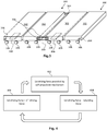
Figure 1 is a simplified schematic of an example of a print media transport apparatus; -
Figures 2 and3 are simplified schematics of examples of pallets; -
Figure 4 is a flowchart of an example of a method of driving a pallet around a track; -
Figure 5a and 5b show the currents supplied to a pallet self-propulsion mechanism according to two example schemes for driving a pallet; and -
Figure 6 is a flowchart of another example of a method of driving a pallet around a track. -
Figure 1 shows a block diagram of an example of a printmedia transport apparatus 100 comprising a plurality ofpallets 102 which, as will be described in greater detail in relation to the example ofFigure 2 below, each have a self-propulsion mechanism, and are to support print media, i.e. a substrate to which a printed image, text or the like may be applied. Such print media may for example comprise a sheet material, such as paper, card stock, plastics, and the like, and may be rigid, substantially rigid or flexible. - The
pallets 102 circulate on anendless track 104. Thetrack 104 comprises aprinting zone 106, a descendingzone 108 and anascending zone 110. In the example ofFigure 1 , thepallets 102 circulate in a clockwise direction and thetrack 104 is substantially ovoid having a substantiallyhorizontal printing zone 106 and a substantially horizontal return zone linking thedescending zone 108 and theascending zone 110. In other examples, other (for example more convoluted) tracks may be provided. - While print media is conveyed over the
printing zone 106 of thetrack 104, inks, toners and the like may be applied to media supported by one orseveral pallets 102 by an associated printer (not shown). In some examples,pallets 102 on theprinting zone 106 are controlled such that at least twopallets 102 move as a group across theprinting zone 106 of thetrack 104 when supporting print media.Pallets 102 travelling on theprinting zone 106 may thereby form a virtual table on which media is supported and carried relative to a printing mechanism of an associated printer. The printing mechanism may for example be associated with an ink supply and comprise a printhead mounted on a moveable carriage, an array of static printheads or the like. The printhead(s) may eject drops of ink through orifices or nozzles and towards a print media so as to print onto the media. - The
apparatus 100 further comprises acontroller 112 to control the self-propulsion mechanisms of thepallets 102, such that apallet 102 on the descendingzone 108 is at least partially supported by anotherpallet 102 which is ahead on thetrack 104, and apallet 102 on theascending zone 110 is at least partially driven bypallet 102 which follows on thetrack 104. Thecontroller 112 may comprise processing apparatus, such as a computer or the like, and may execute machine readable instructions in order to control the movement of thepallets 102. In this example, thecontroller 112 is shown as part of theapparatus 100. In other examples, thecontroller 112 may be mounted on a pallet 102 (or the functions thereof may be distributed over several pallets 102), or thecontroller 112 may be separate, even remote, from thebelt 104. -
Figure 2 shows an example of apallet 102. In this example, thepallet 102 comprises aframe 202 and self-propulsion mechanism which comprises twolinear motors 204 andcontrol circuitry 208, which comprises motor drivers and some processing circuitry. Thepallet 102 further comprisesbearings 206 which are intended to run along the track 104 (which in this example comprises two spaced rails, which may be shaped so as to retain the bearings 206) supported by theframe 202 and driven by themotors 204. In other examples, other propulsion mechanisms (such as magnetic mechanisms or the like) may be used to provide the self-propulsion mechanism for apallet 102. In this example themotor 204 is powered using power collected bybrushes 210, which interact with a power supply loop (not shown). In other examples, the power may be provided in another manner, such as by a battery mounted on thepallet 102 or the like. - The
motors 204 are controlled by thecontrol circuitry 208, itself controlled by thecontroller 112 of the printmedia transport apparatus 100. In one example, processing apparatus within thecontrol circuitry 208 and thecontroller 112 communicate wirelessly. Such communication may comprise commands such as start and stop commands, requests for status updates, and the like. The status updates may for example to be to provide feedback to control loops and readings acquired by any sensors (for example hall effect sensors) mounted on apallet 102. - In an example, the
control circuitry 208 and thecontroller 112 act to control the motion of thepallets 102 such that, while apallet 102 is on theprinting zone 106, the motion (e.g. speed and/or location) is controlled to within a tolerance band. This may be a relatively tight tolerance band as accurate motion allows for predictable application of inks, toners and the like to media supported by thepallets 102. In some practical examples, the location of apallet 102 is controlled to within 10 microns while on theprinting zone 106 of thetrack 104. This may be, for example, to ensure that thepallet 102 places media at an appropriate location for a drop of ink or the like to land, based on the time at which the drop is emitted. In some examples, therefore thepallets 102 are individually controlled while a pallet is on theprinting zone 106 in a precision mode. However, outside thiszone 106, for example while apallet 102 is on the descending orascending zones -
Figure 3 shows an example in which twopallets 300 are coupled together. In this example thepallets 300 comprise two bar-like portions 302, theportions 302 being coupled in a substantially parallel configuration, the coupling allowing relative rotation between theportions 302. Thepallets 300 are coupled to one another with a coupling allowing a variable spacing between thepallets 300. In this example, a slotted coupling 304 (for example, a metal coupling) connectspegs 306 provided on eachpallet 300. Thepegs 306 of thepallets 300 can be separated by the length of the slot in theslotted coupling 304, or thepallets 300 can move closer to one another until they are touching. The slottedcoupling 304 also allows thepallets 300 to rotate relative to one another as they round the turns in thetrack 104. One of theportions 302 comprises a self-propulsion mechanism 308, the other being driven by theportion 302 having a self-propulsion mechanism 308.Such pallets 300 may be joined in an endless loop. - The self-propulsion mechanisms of the
pallets controller 112 such that, whilepallets printing zone 106 of thetrack 104, the spacing remains constant (which allows for accurate media placement within the printing zone) and, while apallet track 104, the spacing is at a minimum (i.e. thepallets track 104 such that thepallets zone 108 can act on thepallets pallets pallets - Control of the
pallets Figure 4 . When apallet printing zone 106 of thetrack 104, it is driven with a first driving force provided by a self-propulsion mechanism of thepallet 102, 300 (block 402). In a descendingpotion 108 of a track, a retarding force is applied by at least oneother pallet ascending zone 110 of the track, a second driving force is provided by at least oneother pallet pallet zone 108 of thetrack 104. The retarding force and/or the second driving force may be transmitted via at least oneintermediate pallet pallet ascending zone 110 of thetrack 104 and thepallet descending zone 108 of the track 104 (i.e. via at least oneintermediate pallet -
Figures 5a and 5b compare the current delivered to a self-propulsion mechanism according to two schemes for driving apallet Figure 5a , eachpallet pallet ascending zone 110 of the track, the current shows a peak as thepallet pallet descending zone 108 of thetrack 104, the current shows a dip as gravity is resisted. These peak and trough currents are opposite in direction but each will result in additional heating of a motor and any associated drivers, which should be taken into account at the time the self-propulsion mechanism is designed. In addition, the motors of a self-propulsion mechanism are sized for these peak currents. For completeness, it is noted that the rapid, relatively large, fluctuation to the right of the graph is an artefact arising from a gap in the encoder used monitor the pallet location, and not a result of any control of the power/current levels. As can be seen from the Figure, the average current varies significantly between different zones of the track. -
Figure 5b shows the current delivered to drive apallet Figure 4 . In this example, the current variability is much lower- the average current being supplied in eachzone Figures 5a and 5b , the current (and power) supplied to a self-propulsion mechanism of anindividual pallet zone 110 oftrack 104 is insufficient to allow thatpallet zone 110 of track 104 (an additional driving force supplied by the action of a descendingpallet Figure 5a . In a practical example, supplying current as shown inFigure 5b may result in a power saving of about 1/3 to 1/2 compared to the scheme illustrated inFigure 5a . - The method of
Figure 4 may be achieved by supplying power or current to the propulsion mechanism of eachpallet track 104. The actual variability of the current will dependent on factors such as the friction encountered in an apparatus. However, in some examples, the current may be within a range of 50% of the average current. Moreover, the average current supplied while a pallet traverses a particular zone is substantially equal for all zones (or at least for the ascending and descendingzones 108, 110). Effectively, ascendingpallets pallets pallets pallets track 104. - Considered in another way, as shown in
Figure 6 , inblock 602, a first, second andthird pallet endless track 104 of a printmedia transport apparatus 100. Thefirst pallet second pallet second pallet third pallet block 604, a self-propulsion mechanism of each of the first, second andthird pallet descending zone 108 of thetrack 104, thefirst pallet second pallet ascending zone 110 of thetrack 104, thethird pallet second pallet - As noted above, while the pallet movements may be accurately controlled while a
pallet printing zone 106 of thetrack 104, this may be less of a concern in other zones of thetrack 104. - Examples in the present disclosure can be provided as methods, systems or machine readable instructions, such as any combination of software, hardware, firmware or the like, which may for example be executed by the
controller 112 or thecontrol circuitry 208. Such machine readable instructions may be included on a computer readable storage medium (including but is not limited to disc storage, CD-ROM, optical storage, etc.) having computer readable program codes therein or thereon. The machine readable instructions may, for example, be executed by a general purpose computer, a special purpose computer, an embedded processor or processors of other programmable data processing devices to realize the functions of thecontroller 112 and/orcontrol circuitry 208 described in the description and diagrams. In particular, a processor or processing apparatus may execute the machine readable instructions. Thus functional modules of the apparatus and devices may be implemented by a processor executing machine readable instructions stored in a memory, or a processor operating in accordance with instructions embedded in logic circuitry. The term 'processor' is to be interpreted broadly to include a CPU, processing unit, ASIC, logic unit, or programmable gate array etc. The methods and functional modules may all be performed by a single processor or divided amongst several processors. - Further, the teachings herein may be implemented in the form of a computer software product, the computer software product being stored in a storage medium and comprising a plurality of instructions for making a computer device implement the methods recited in the examples of the present disclosure.
- The present disclosure is described with reference to flow diagrams. Although the flow diagrams described above show a specific order of execution, the order of execution may differ from that which is depicted. It shall be understood that each block in the flow diagrams, as well as combinations thereof can be realized by machine readable instructions.
- Features described in relation to one example may be combined with features described in relation to any other example. Thus, a feature described in relation to a
pallet 102 as shown inFigure 2 , may be present on apallet 300 as shown inFigure 3 , and vice versa. - While the method, apparatus and related aspects have been described with reference to certain examples, various modifications, changes, omissions, and substitutions can be made without departing from the spirit of the present disclosure. It is intended, therefore, that the method, apparatus and related aspects be limited only by the scope of the following claims and their equivalents. It should be noted that the above-mentioned examples illustrate rather than limit what is described herein, and that those skilled in the art will be able to design many alternative implementations without departing from the scope of the appended claims.
- The word "comprising" does not exclude the presence of elements other than those listed in a claim, "a" or "an" does not exclude a plurality, and a single processor or other unit may fulfil the functions of several units recited in the claims.
- The features of any dependent claim may be combined with the features of any of the independent claims or other dependent claims.
- In some examples, the invention may be described by any of the following numbered statements.
- Statement 1. A print media transport apparatus comprising: a plurality of pallets having a self-propulsion mechanism, and being to support print media; an endless track on which the plurality of pallets circulate, the track comprising a printing zone, a descending zone and an ascending zone, a controller to control the self-propulsion mechanisms of the pallets such that a pallet on the descending zone is at least partially supported by another pallet which is ahead on the track, and a pallet on the ascending zone is at least partially driven by pallet which follows on the track.
- Statement2. A print media transport apparatus according to statement 1 in which pallets are linked in an endless loop, the pallets being coupled with a coupling allowing a variable spacing between the pallets, wherein controller is to drive the pallets such that: while a pallet is on the printing zone of the track, the spacing remains constant, and, while a pallet is on the descending and ascending zones of the track, the spacing is at a minimum.
- Statement3. A print media transport apparatus according to statement 1 in which the controller is to control the speed of the pallets such that,
- while a pallet is on the printing zone of the track, the speed is maintained to within a tolerance band, and, in another zone of the track, the speed varies outside the tolerance band.
- Statement 4. A print media transport apparatus according to statement 1 in which each pallet comprises at least two portions, the portions being coupled in a substantially parallel configuration, the coupling allowing relative rotation between the portions.
- Statement 5. A print media transport apparatus according to statement 4 in which the self-propulsion mechanism is mounted on one of the portions.
- Statement 6. A method comprising: driving a pallet around an endless track, the endless track having an ascending zone and a descending zone and being associated with a printer, and the pallet being to convey print media to be printed by the printer, the method comprising driving the pallet with a first driving force provided by a propulsion mechanism of the pallet and, in at least the ascending zone of the track, a second driving force provided by at least one other pallet on the track.
- Statement 7. A method according to statement 6 in which the second driving force is provided by gravity acting on at least one pallet on the descending zone of the track.
- Statement 8. A method according to statement 7, in which the second driving force is transmitted via at least one intermediate pallet between the pallet on the ascending zone of the track and the pallet on the descending zone of the track.
- Statement 9. A method according to statement 6 comprising supplying power to the propulsion mechanism of the pallet at a substantially constant average level for all zones of the track.
- Statement 10. A method according to statement 6 in which, while a pallet is on descending zone of the track, a retarding force is applied thereto by at least one other pallet on the track.
- Statement 11. A method, comprising: providing a first, second and third pallet on an endless track of a print media transport apparatus, wherein the first pallet precedes the second pallet and the second pallet precedes the third pallet, controlling a self-propulsion mechanism of each of the first, second and third pallet on the endless track such that, on a descending zone of the track, the first pallet at least partially supports the second pallet and on an ascending zone of the track, the third pallet at least partially drives the second pallet.
- Statement 12. A method according to statement 11 wherein controlling the self-propulsion mechanism comprises controlling the power supplied to the self-propulsion mechanism such that the average power is approximately equal for the descending and ascending zones of the track.
- Statement 13. A method according to statement 11 wherein controlling the self-propulsion mechanism comprises controlling the current supplied to the self-propulsion mechanism such that the average current is approximately equal for the descending and ascending zones of the track.
- Statement 14. A method according to statement 11 wherein controlling the self-propulsion mechanism comprises controlling the power supplied to the self-propulsion mechanism such that the power supplied to an individual pallet on the ascending zone of track is insufficient to allow that pallet to climb the ascending zone of track.
- Statement 15. A method according to statement 11 in which the pallets are intended to support a print media during application of print materials thereto, the method comprising controlling the position of the pallets such that at least two pallets move as a group across a horizontal zone of a track when supporting print media.
Claims (16)
- A print media transport apparatus comprising:an endless track comprising a printing zone, a descending zone and an ascending zone,a plurality of pallets circulating on the endless track, each pallet of the plurality of pallets comprising a self-propelling mechanism and having a upper surface to support print media, the plurality of pallets forming an endless loop, adjacent pallets being linked by a coupling allowing variable spacing between the adjacent pallets, wherein while a pallet is on the printing zone of the track, the spacing remains constant, and while a pallet is on the descending and ascending zones of the track, the spacing is at a minimum, anda controller controlling the self-propelling mechanism of each pallet.
- The apparatus of claim 1, in which the coupling connecting adjacent pallets is a slotted coupling.
- The apparatus of claim 2, in which the slotted coupling connects pegs on each adjacent pallet.
- The apparatus of any of claims 1 to 3, in which the self-propelling mechanism of each pallet has a substantially constant rate of power consumption in both the descending zone and the ascending zone.
- The apparatus of claim 4, in which the power supplied to a self-propulsion mechanism of an individual pallet on the ascending zone of the track is insufficient to allow that pallet to climb the ascending zone of track without a driving force from a descending pallet.
- A print media transport apparatus comprising:an endless track comprising: a printing zone, a descending zone, a return zone, and an ascending zone; anda plurality of pallets circulating on the endless track, each pallet of the plurality of pallets comprising a self-propelling mechanism and having an upper surface to support print media, the plurality of pallets forming an endless loop, wherein each pallet in the ascending zone is partially lifted by a driving force provided by a pallet in the descending zone through a pallet in the return zone.
- The apparatus of claim 6, in which the power provided to each self-propelling mechanism is substantially the same when a pallet is in the descending zone and ascending zone.
- The apparatus of claim 7, in which power provided to each self-propulsion mechanism of a pallet at a substantially constant average level for all zones of the track.
- The apparatus of any of claims 6-8, in which, while a pallet is on descending zone of the track, a retarding force is applied thereto by at least one other pallet on the track.
- The apparatus of claim 9, in which the at least one other pallet is located in the return zone.
- A print media transport apparatus comprising:an endless track comprising: a printing zone, a descending zone, and an ascending zone; anda plurality of pallets, the plurality of pallets circulating on the endless track, each pallet comprising a self-propelling mechanism;a controller, in which the controller is to control self-propelling mechanism of each pallet and the power to each propulsion mechanism is at a substantially constant level for all zones of the track.
- The apparatus of claim 11, in which the power supplied to a self-propulsion mechanism of an individual pallet on the ascending zone of the track is insufficient to allow that pallet to climb the ascending zone of track without a driving force from a descending pallet.
- The apparatus of claim 11 or 12, in which adjacent pallets are tightly packed in the ascending zone.
- The apparatus of any of claims 11 to 13, in which adjacent pallets are tightly packed in the descending zone.
- The apparatus of any of claims 11 to 14, in which adjacent pallets are spaced while in the printing zone.
- The apparatus of any of claims 11 to 16 in which adjacent pallets are connected by a coupling allowing variable spacing between the adjacent pallets.
Priority Applications (1)
| Application Number | Priority Date | Filing Date | Title |
|---|---|---|---|
| EP18154103.8A EP3342597B1 (en) | 2015-07-31 | 2015-07-31 | Print media transport apparatus |
Applications Claiming Priority (2)
| Application Number | Priority Date | Filing Date | Title |
|---|---|---|---|
| EP18154103.8A EP3342597B1 (en) | 2015-07-31 | 2015-07-31 | Print media transport apparatus |
| EP15179407.0A EP3124263B1 (en) | 2015-07-31 | 2015-07-31 | Print media transport apparatus |
Related Parent Applications (2)
| Application Number | Title | Priority Date | Filing Date |
|---|---|---|---|
| EP15179407.0A Division EP3124263B1 (en) | 2015-07-31 | 2015-07-31 | Print media transport apparatus |
| EP15179407.0A Division-Into EP3124263B1 (en) | 2015-07-31 | 2015-07-31 | Print media transport apparatus |
Publications (2)
| Publication Number | Publication Date |
|---|---|
| EP3342597A1 true EP3342597A1 (en) | 2018-07-04 |
| EP3342597B1 EP3342597B1 (en) | 2022-04-06 |
Family
ID=53794067
Family Applications (2)
| Application Number | Title | Priority Date | Filing Date |
|---|---|---|---|
| EP15179407.0A Active EP3124263B1 (en) | 2015-07-31 | 2015-07-31 | Print media transport apparatus |
| EP18154103.8A Active EP3342597B1 (en) | 2015-07-31 | 2015-07-31 | Print media transport apparatus |
Family Applications Before (1)
| Application Number | Title | Priority Date | Filing Date |
|---|---|---|---|
| EP15179407.0A Active EP3124263B1 (en) | 2015-07-31 | 2015-07-31 | Print media transport apparatus |
Country Status (4)
| Country | Link |
|---|---|
| US (2) | US9796548B2 (en) |
| EP (2) | EP3124263B1 (en) |
| JP (2) | JP6336527B2 (en) |
| CN (1) | CN106394011B (en) |
Families Citing this family (4)
| Publication number | Priority date | Publication date | Assignee | Title |
|---|---|---|---|---|
| EP3124263B1 (en) * | 2015-07-31 | 2018-05-16 | HP Scitex Ltd | Print media transport apparatus |
| US11072398B2 (en) * | 2016-08-12 | 2021-07-27 | Illinois Tool Works Inc. | Apparatuses and methods for high-resolution printing |
| EP3315309B1 (en) * | 2016-10-31 | 2021-08-04 | HP Scitex Ltd | Vacuum within a pallet conveyor for a printing system |
| CN107284046A (en) * | 2017-07-30 | 2017-10-24 | 合肥岸鲁意科技有限公司 | A kind of double fabrics of cycle rotation are while stamp digital inkjet printing machine and printing method |
Citations (1)
| Publication number | Priority date | Publication date | Assignee | Title |
|---|---|---|---|---|
| US20100225719A1 (en) * | 2009-03-04 | 2010-09-09 | Fujufilm Corporation | Transporting device and liquid ejecting apparatus |
Family Cites Families (14)
| Publication number | Priority date | Publication date | Assignee | Title |
|---|---|---|---|---|
| US6126384A (en) | 1995-06-07 | 2000-10-03 | Standard Duplicating Machines Corporation | Paper set feeding |
| US5921368A (en) | 1997-02-25 | 1999-07-13 | Knight Industries, Inc. | Linked carrier gravity conveyor |
| JP4323758B2 (en) * | 2002-05-24 | 2009-09-02 | 日本電産サンキョー株式会社 | Work transfer system |
| JP2003345212A (en) * | 2002-05-30 | 2003-12-03 | Ricoh Co Ltd | Image forming device |
| JP2004299884A (en) | 2003-03-31 | 2004-10-28 | Fuji Photo Film Co Ltd | Sheet ejector |
| JP5196918B2 (en) * | 2007-08-30 | 2013-05-15 | 株式会社ミマキエンジニアリング | Manufacturing method of printing apparatus |
| EP2106916B1 (en) * | 2008-03-31 | 2011-05-04 | Dainippon Screen Mfg., Co., Ltd. | Image recording apparatus |
| JP5016539B2 (en) * | 2008-03-31 | 2012-09-05 | 大日本スクリーン製造株式会社 | Recording medium transport device |
| JP5037431B2 (en) * | 2008-05-28 | 2012-09-26 | 大日本スクリーン製造株式会社 | Recording medium conveying apparatus in image recording apparatus |
| US9067408B2 (en) * | 2011-02-10 | 2015-06-30 | Hewlett-Packard Development Company, L.P. | Printing media supportable on movable pallets |
| US9056620B2 (en) | 2012-12-06 | 2015-06-16 | Gary D. Copus | Material handling and load conveyance system |
| EP3018081B1 (en) * | 2014-11-06 | 2017-08-02 | Hewlett-Packard Industrial Printing Ltd. | Pallet conveyors for printers |
| JP6607343B2 (en) * | 2015-03-30 | 2019-11-20 | パナソニックIpマネジメント株式会社 | Printing apparatus and method for manufacturing thin-film printed body |
| EP3124263B1 (en) * | 2015-07-31 | 2018-05-16 | HP Scitex Ltd | Print media transport apparatus |
-
2015
- 2015-07-31 EP EP15179407.0A patent/EP3124263B1/en active Active
- 2015-07-31 EP EP18154103.8A patent/EP3342597B1/en active Active
-
2016
- 2016-07-27 US US15/221,469 patent/US9796548B2/en active Active
- 2016-07-29 CN CN201610610172.XA patent/CN106394011B/en active Active
- 2016-07-29 JP JP2016149642A patent/JP6336527B2/en active Active
-
2017
- 2017-09-08 US US15/698,831 patent/US10189663B2/en active Active
-
2018
- 2018-05-01 JP JP2018088202A patent/JP6684305B2/en active Active
Patent Citations (1)
| Publication number | Priority date | Publication date | Assignee | Title |
|---|---|---|---|---|
| US20100225719A1 (en) * | 2009-03-04 | 2010-09-09 | Fujufilm Corporation | Transporting device and liquid ejecting apparatus |
Also Published As
| Publication number | Publication date |
|---|---|
| US9796548B2 (en) | 2017-10-24 |
| JP2017036150A (en) | 2017-02-16 |
| EP3124263B1 (en) | 2018-05-16 |
| US20170029228A1 (en) | 2017-02-02 |
| JP2018158841A (en) | 2018-10-11 |
| US10189663B2 (en) | 2019-01-29 |
| JP6684305B2 (en) | 2020-04-22 |
| EP3124263A1 (en) | 2017-02-01 |
| CN106394011A (en) | 2017-02-15 |
| EP3342597B1 (en) | 2022-04-06 |
| CN106394011B (en) | 2019-12-17 |
| JP6336527B2 (en) | 2018-06-06 |
| US20170369263A1 (en) | 2017-12-28 |
Similar Documents
| Publication | Publication Date | Title |
|---|---|---|
| US10189663B2 (en) | Print media transport apparatus | |
| US9421795B2 (en) | Pallet conveyors for printers | |
| CN101823642B (en) | Floating-type automatic tensioning feeding device | |
| US8042933B2 (en) | Forceless support frame for printhead shuttle in digital printers | |
| CN105966949B (en) | Printing machine with transport system | |
| US20130293653A1 (en) | Air bearing substrate media transport | |
| US9067408B2 (en) | Printing media supportable on movable pallets | |
| CN1611367A (en) | Printer and paper feed controller | |
| EP1705024A3 (en) | Ink-jet recording apparatus with conveyor belt cleaning means | |
| CN109153270A (en) | Apparatus and method for printing printed matter | |
| US9284140B2 (en) | Belt conveyance device, media conveyance device, and printer | |
| US10730286B2 (en) | Image recording apparatus | |
| CN201703900U (en) | Float type automatic tensioning feeding device | |
| KR20160047941A (en) | Conveyor device | |
| CN105197520A (en) | Flexible vehicle body storage and transportation system | |
| CN204955754U (en) | Printer with tension regulating action | |
| EP3199359A3 (en) | A control assembly | |
| CN203753795U (en) | Transmission belt transportation machine | |
| CN206551478U (en) | A kind of print head structure of slidingtype motion | |
| JP2019010742A (en) | Liquid injection device | |
| JP2013022917A (en) | Recording apparatus, controller, control method for the recording apparatus, and program | |
| TH1801006096A (en) | Control of print head in digital printer | |
| JP2005169942A (en) | Recording apparatus, motor control apparatus, and motor control method | |
| JP2013215913A (en) | Recording device, control method of recording device, and control program of recording device | |
| WO2017171541A3 (en) | Control of printing operation of printing heads in a digital printing apparatus |
Legal Events
| Date | Code | Title | Description |
|---|---|---|---|
| PUAI | Public reference made under article 153(3) epc to a published international application that has entered the european phase |
Free format text: ORIGINAL CODE: 0009012 |
|
| STAA | Information on the status of an ep patent application or granted ep patent |
Free format text: STATUS: REQUEST FOR EXAMINATION WAS MADE |
|
| 17P | Request for examination filed |
Effective date: 20180130 |
|
| AC | Divisional application: reference to earlier application |
Ref document number: 3124263 Country of ref document: EP Kind code of ref document: P |
|
| AK | Designated contracting states |
Kind code of ref document: A1 Designated state(s): AL AT BE BG CH CY CZ DE DK EE ES FI FR GB GR HR HU IE IS IT LI LT LU LV MC MK MT NL NO PL PT RO RS SE SI SK SM TR |
|
| STAA | Information on the status of an ep patent application or granted ep patent |
Free format text: STATUS: EXAMINATION IS IN PROGRESS |
|
| 17Q | First examination report despatched |
Effective date: 20200723 |
|
| GRAP | Despatch of communication of intention to grant a patent |
Free format text: ORIGINAL CODE: EPIDOSNIGR1 |
|
| STAA | Information on the status of an ep patent application or granted ep patent |
Free format text: STATUS: GRANT OF PATENT IS INTENDED |
|
| INTG | Intention to grant announced |
Effective date: 20211214 |
|
| GRAS | Grant fee paid |
Free format text: ORIGINAL CODE: EPIDOSNIGR3 |
|
| GRAA | (expected) grant |
Free format text: ORIGINAL CODE: 0009210 |
|
| STAA | Information on the status of an ep patent application or granted ep patent |
Free format text: STATUS: THE PATENT HAS BEEN GRANTED |
|
| AC | Divisional application: reference to earlier application |
Ref document number: 3124263 Country of ref document: EP Kind code of ref document: P |
|
| AK | Designated contracting states |
Kind code of ref document: B1 Designated state(s): AL AT BE BG CH CY CZ DE DK EE ES FI FR GB GR HR HU IE IS IT LI LT LU LV MC MK MT NL NO PL PT RO RS SE SI SK SM TR |
|
| REG | Reference to a national code |
Ref country code: GB Ref legal event code: FG4D |
|
| REG | Reference to a national code |
Ref country code: CH Ref legal event code: EP |
|
| REG | Reference to a national code |
Ref country code: AT Ref legal event code: REF Ref document number: 1480974 Country of ref document: AT Kind code of ref document: T Effective date: 20220415 |
|
| REG | Reference to a national code |
Ref country code: IE Ref legal event code: FG4D |
|
| REG | Reference to a national code |
Ref country code: DE Ref legal event code: R096 Ref document number: 602015078139 Country of ref document: DE |
|
| REG | Reference to a national code |
Ref country code: LT Ref legal event code: MG9D |
|
| REG | Reference to a national code |
Ref country code: NL Ref legal event code: MP Effective date: 20220406 |
|
| REG | Reference to a national code |
Ref country code: AT Ref legal event code: MK05 Ref document number: 1480974 Country of ref document: AT Kind code of ref document: T Effective date: 20220406 |
|
| PG25 | Lapsed in a contracting state [announced via postgrant information from national office to epo] |
Ref country code: NL Free format text: LAPSE BECAUSE OF FAILURE TO SUBMIT A TRANSLATION OF THE DESCRIPTION OR TO PAY THE FEE WITHIN THE PRESCRIBED TIME-LIMIT Effective date: 20220406 |
|
| PG25 | Lapsed in a contracting state [announced via postgrant information from national office to epo] |
Ref country code: SE Free format text: LAPSE BECAUSE OF FAILURE TO SUBMIT A TRANSLATION OF THE DESCRIPTION OR TO PAY THE FEE WITHIN THE PRESCRIBED TIME-LIMIT Effective date: 20220406 Ref country code: PT Free format text: LAPSE BECAUSE OF FAILURE TO SUBMIT A TRANSLATION OF THE DESCRIPTION OR TO PAY THE FEE WITHIN THE PRESCRIBED TIME-LIMIT Effective date: 20220808 Ref country code: NO Free format text: LAPSE BECAUSE OF FAILURE TO SUBMIT A TRANSLATION OF THE DESCRIPTION OR TO PAY THE FEE WITHIN THE PRESCRIBED TIME-LIMIT Effective date: 20220706 Ref country code: LT Free format text: LAPSE BECAUSE OF FAILURE TO SUBMIT A TRANSLATION OF THE DESCRIPTION OR TO PAY THE FEE WITHIN THE PRESCRIBED TIME-LIMIT Effective date: 20220406 Ref country code: HR Free format text: LAPSE BECAUSE OF FAILURE TO SUBMIT A TRANSLATION OF THE DESCRIPTION OR TO PAY THE FEE WITHIN THE PRESCRIBED TIME-LIMIT Effective date: 20220406 Ref country code: GR Free format text: LAPSE BECAUSE OF FAILURE TO SUBMIT A TRANSLATION OF THE DESCRIPTION OR TO PAY THE FEE WITHIN THE PRESCRIBED TIME-LIMIT Effective date: 20220707 Ref country code: FI Free format text: LAPSE BECAUSE OF FAILURE TO SUBMIT A TRANSLATION OF THE DESCRIPTION OR TO PAY THE FEE WITHIN THE PRESCRIBED TIME-LIMIT Effective date: 20220406 Ref country code: ES Free format text: LAPSE BECAUSE OF FAILURE TO SUBMIT A TRANSLATION OF THE DESCRIPTION OR TO PAY THE FEE WITHIN THE PRESCRIBED TIME-LIMIT Effective date: 20220406 Ref country code: BG Free format text: LAPSE BECAUSE OF FAILURE TO SUBMIT A TRANSLATION OF THE DESCRIPTION OR TO PAY THE FEE WITHIN THE PRESCRIBED TIME-LIMIT Effective date: 20220706 Ref country code: AT Free format text: LAPSE BECAUSE OF FAILURE TO SUBMIT A TRANSLATION OF THE DESCRIPTION OR TO PAY THE FEE WITHIN THE PRESCRIBED TIME-LIMIT Effective date: 20220406 |
|
| PG25 | Lapsed in a contracting state [announced via postgrant information from national office to epo] |
Ref country code: RS Free format text: LAPSE BECAUSE OF FAILURE TO SUBMIT A TRANSLATION OF THE DESCRIPTION OR TO PAY THE FEE WITHIN THE PRESCRIBED TIME-LIMIT Effective date: 20220406 Ref country code: PL Free format text: LAPSE BECAUSE OF FAILURE TO SUBMIT A TRANSLATION OF THE DESCRIPTION OR TO PAY THE FEE WITHIN THE PRESCRIBED TIME-LIMIT Effective date: 20220406 Ref country code: LV Free format text: LAPSE BECAUSE OF FAILURE TO SUBMIT A TRANSLATION OF THE DESCRIPTION OR TO PAY THE FEE WITHIN THE PRESCRIBED TIME-LIMIT Effective date: 20220406 Ref country code: IS Free format text: LAPSE BECAUSE OF FAILURE TO SUBMIT A TRANSLATION OF THE DESCRIPTION OR TO PAY THE FEE WITHIN THE PRESCRIBED TIME-LIMIT Effective date: 20220806 |
|
| REG | Reference to a national code |
Ref country code: DE Ref legal event code: R097 Ref document number: 602015078139 Country of ref document: DE |
|
| PG25 | Lapsed in a contracting state [announced via postgrant information from national office to epo] |
Ref country code: SM Free format text: LAPSE BECAUSE OF FAILURE TO SUBMIT A TRANSLATION OF THE DESCRIPTION OR TO PAY THE FEE WITHIN THE PRESCRIBED TIME-LIMIT Effective date: 20220406 Ref country code: SK Free format text: LAPSE BECAUSE OF FAILURE TO SUBMIT A TRANSLATION OF THE DESCRIPTION OR TO PAY THE FEE WITHIN THE PRESCRIBED TIME-LIMIT Effective date: 20220406 Ref country code: RO Free format text: LAPSE BECAUSE OF FAILURE TO SUBMIT A TRANSLATION OF THE DESCRIPTION OR TO PAY THE FEE WITHIN THE PRESCRIBED TIME-LIMIT Effective date: 20220406 Ref country code: EE Free format text: LAPSE BECAUSE OF FAILURE TO SUBMIT A TRANSLATION OF THE DESCRIPTION OR TO PAY THE FEE WITHIN THE PRESCRIBED TIME-LIMIT Effective date: 20220406 Ref country code: DK Free format text: LAPSE BECAUSE OF FAILURE TO SUBMIT A TRANSLATION OF THE DESCRIPTION OR TO PAY THE FEE WITHIN THE PRESCRIBED TIME-LIMIT Effective date: 20220406 Ref country code: CZ Free format text: LAPSE BECAUSE OF FAILURE TO SUBMIT A TRANSLATION OF THE DESCRIPTION OR TO PAY THE FEE WITHIN THE PRESCRIBED TIME-LIMIT Effective date: 20220406 |
|
| PLBE | No opposition filed within time limit |
Free format text: ORIGINAL CODE: 0009261 |
|
| STAA | Information on the status of an ep patent application or granted ep patent |
Free format text: STATUS: NO OPPOSITION FILED WITHIN TIME LIMIT |
|
| PG25 | Lapsed in a contracting state [announced via postgrant information from national office to epo] |
Ref country code: MC Free format text: LAPSE BECAUSE OF FAILURE TO SUBMIT A TRANSLATION OF THE DESCRIPTION OR TO PAY THE FEE WITHIN THE PRESCRIBED TIME-LIMIT Effective date: 20220406 |
|
| REG | Reference to a national code |
Ref country code: CH Ref legal event code: PL |
|
| 26N | No opposition filed |
Effective date: 20230110 |
|
| REG | Reference to a national code |
Ref country code: BE Ref legal event code: MM Effective date: 20220731 |
|
| PG25 | Lapsed in a contracting state [announced via postgrant information from national office to epo] |
Ref country code: AL Free format text: LAPSE BECAUSE OF FAILURE TO SUBMIT A TRANSLATION OF THE DESCRIPTION OR TO PAY THE FEE WITHIN THE PRESCRIBED TIME-LIMIT Effective date: 20220406 |
|
| PG25 | Lapsed in a contracting state [announced via postgrant information from national office to epo] |
Ref country code: LU Free format text: LAPSE BECAUSE OF NON-PAYMENT OF DUE FEES Effective date: 20220731 Ref country code: LI Free format text: LAPSE BECAUSE OF NON-PAYMENT OF DUE FEES Effective date: 20220731 Ref country code: CH Free format text: LAPSE BECAUSE OF NON-PAYMENT OF DUE FEES Effective date: 20220731 |
|
| PG25 | Lapsed in a contracting state [announced via postgrant information from national office to epo] |
Ref country code: SI Free format text: LAPSE BECAUSE OF FAILURE TO SUBMIT A TRANSLATION OF THE DESCRIPTION OR TO PAY THE FEE WITHIN THE PRESCRIBED TIME-LIMIT Effective date: 20220406 Ref country code: BE Free format text: LAPSE BECAUSE OF NON-PAYMENT OF DUE FEES Effective date: 20220731 |
|
| PG25 | Lapsed in a contracting state [announced via postgrant information from national office to epo] |
Ref country code: IE Free format text: LAPSE BECAUSE OF NON-PAYMENT OF DUE FEES Effective date: 20220731 |
|
| PGFP | Annual fee paid to national office [announced via postgrant information from national office to epo] |
Ref country code: FR Payment date: 20230621 Year of fee payment: 9 |
|
| PGFP | Annual fee paid to national office [announced via postgrant information from national office to epo] |
Ref country code: GB Payment date: 20230620 Year of fee payment: 9 |
|
| PG25 | Lapsed in a contracting state [announced via postgrant information from national office to epo] |
Ref country code: IT Free format text: LAPSE BECAUSE OF FAILURE TO SUBMIT A TRANSLATION OF THE DESCRIPTION OR TO PAY THE FEE WITHIN THE PRESCRIBED TIME-LIMIT Effective date: 20220406 |
|
| PG25 | Lapsed in a contracting state [announced via postgrant information from national office to epo] |
Ref country code: HU Free format text: LAPSE BECAUSE OF FAILURE TO SUBMIT A TRANSLATION OF THE DESCRIPTION OR TO PAY THE FEE WITHIN THE PRESCRIBED TIME-LIMIT; INVALID AB INITIO Effective date: 20150731 |
|
| PG25 | Lapsed in a contracting state [announced via postgrant information from national office to epo] |
Ref country code: MK Free format text: LAPSE BECAUSE OF FAILURE TO SUBMIT A TRANSLATION OF THE DESCRIPTION OR TO PAY THE FEE WITHIN THE PRESCRIBED TIME-LIMIT Effective date: 20220406 Ref country code: CY Free format text: LAPSE BECAUSE OF FAILURE TO SUBMIT A TRANSLATION OF THE DESCRIPTION OR TO PAY THE FEE WITHIN THE PRESCRIBED TIME-LIMIT Effective date: 20220406 |
|
| PG25 | Lapsed in a contracting state [announced via postgrant information from national office to epo] |
Ref country code: TR Free format text: LAPSE BECAUSE OF FAILURE TO SUBMIT A TRANSLATION OF THE DESCRIPTION OR TO PAY THE FEE WITHIN THE PRESCRIBED TIME-LIMIT Effective date: 20220406 |
|
| PG25 | Lapsed in a contracting state [announced via postgrant information from national office to epo] |
Ref country code: MT Free format text: LAPSE BECAUSE OF FAILURE TO SUBMIT A TRANSLATION OF THE DESCRIPTION OR TO PAY THE FEE WITHIN THE PRESCRIBED TIME-LIMIT Effective date: 20220406 |
|
| PG25 | Lapsed in a contracting state [announced via postgrant information from national office to epo] |
Ref country code: BG Free format text: LAPSE BECAUSE OF FAILURE TO SUBMIT A TRANSLATION OF THE DESCRIPTION OR TO PAY THE FEE WITHIN THE PRESCRIBED TIME-LIMIT Effective date: 20220406 |
|
| PG25 | Lapsed in a contracting state [announced via postgrant information from national office to epo] |
Ref country code: BG Free format text: LAPSE BECAUSE OF FAILURE TO SUBMIT A TRANSLATION OF THE DESCRIPTION OR TO PAY THE FEE WITHIN THE PRESCRIBED TIME-LIMIT Effective date: 20220406 |
|
| GBPC | Gb: european patent ceased through non-payment of renewal fee |
Effective date: 20240731 |
|
| PG25 | Lapsed in a contracting state [announced via postgrant information from national office to epo] |
Ref country code: FR Free format text: LAPSE BECAUSE OF NON-PAYMENT OF DUE FEES Effective date: 20240731 |
|
| PG25 | Lapsed in a contracting state [announced via postgrant information from national office to epo] |
Ref country code: GB Free format text: LAPSE BECAUSE OF NON-PAYMENT OF DUE FEES Effective date: 20240731 |
|
| PGFP | Annual fee paid to national office [announced via postgrant information from national office to epo] |
Ref country code: DE Payment date: 20250620 Year of fee payment: 11 |