EP3342539B1 - Autofeed automatic screwdriver - Google Patents
Autofeed automatic screwdriver Download PDFInfo
- Publication number
- EP3342539B1 EP3342539B1 EP17210661.9A EP17210661A EP3342539B1 EP 3342539 B1 EP3342539 B1 EP 3342539B1 EP 17210661 A EP17210661 A EP 17210661A EP 3342539 B1 EP3342539 B1 EP 3342539B1
- Authority
- EP
- European Patent Office
- Prior art keywords
- bit
- main duct
- duct
- screw
- automatic screwdriver
- Prior art date
- Legal status (The legal status is an assumption and is not a legal conclusion. Google has not performed a legal analysis and makes no representation as to the accuracy of the status listed.)
- Active
Links
Images


Classifications
-
- B—PERFORMING OPERATIONS; TRANSPORTING
- B25—HAND TOOLS; PORTABLE POWER-DRIVEN TOOLS; MANIPULATORS
- B25B—TOOLS OR BENCH DEVICES NOT OTHERWISE PROVIDED FOR, FOR FASTENING, CONNECTING, DISENGAGING, OR HOLDING
- B25B23/00—Details of, or accessories for, spanners, wrenches, screwdrivers
- B25B23/02—Arrangements for handling screws or nuts
- B25B23/04—Arrangements for handling screws or nuts for feeding screws or nuts
- B25B23/06—Arrangements for handling screws or nuts for feeding screws or nuts using built-in magazine
Definitions
- the invention relates to an autofeed automatic screwdriver.
- the present invention relates to the bit-holding head of an electrically- or pneumatically-operated autofeed automatic screwdriver, to which the following disclosure will make explicit reference without however losing in generality.
- autofeed automatic screwdrivers are electrically- or pneumatically-operated devices that receive in input a succession of screws usually of the self-tapping type, and are adapted to screw in a completely automatic manner the screws into a generic support.
- autofeed automatic screwdrivers comprise: a bit-holding head that houses inside itself the screw bit, receives in input the screws to be screwed, and is adapted to place, in succession, each screw in front of the screw bit, locally coaxial to the same screw bit; and an electric or pneumatic servo-motor which is able to drive into rotation the screw bit around its longitudinal axis and, optionally, also to axially move the screw bit back and forth inside the bit-holding head, so as to cyclically bring the screw bit in abutment against the head of the screw and then push the screw against the support stationary beneath the bit-holding head.
- the bit-holding head is usually provided with a rigid and oblong in shape, outer casing which is provided with a straight main duct, from which the single screws come out in succession and which accommodates the screw bit in axially slidable and rotatable manner, and with a straight secondary duct that branches off from the straight main duct with an inclination angle of about 45° and is dimensioned so as to convey the screws to be screwed in succession in the straight main duct, immediately below the screw bit.
- the bit-holding head additionally also comprises: a bit-holding rod that firmly carries the screw bit at the bottom end and extends inside the outer casing locally coaxial to the straight main duct, with the capability of freely rotating and sliding parallel to its longitudinal axis; a contrast spring which is adapted to elastically hold the bit-holding rod and the screw bit inside the upper portion of the straight main duct, i.e.
- a screw-stop device which is arranged along the lower portion of the straight main duct, immediately downstream of the joining/connecting point with the straight secondary duct, and is capable of stopping the screw inside the straight main duct with the head of the screw facing the screw bit, until the moment when the screw bit reaches and the engages the head of the screw.
- the electric or pneumatic servo-motor is adapted to rotate the bit-holding rod around its longitudinal axis and usually also to axially move the bit-holding rod with respect to the outer casing, so as to cyclically move the screw bit back and forth inside the straight main duct.
- the bit-holding head is moreover provided with a movable deflector member which is located at the joining/connecting point between the two ducts and is structured so as to selectively channel the screws coming out of the straight secondary duct towards the bottom portion of the straight main duct.
- the deflector member consists of a rocker arm which is arranged on the side of the straight main duct, opposite with respect to the mount of the straight secondary duct, and is hinged on the outer casing so as to be capable of rocking on the lying plane of the straight main duct between a first operating position in which the body of the rocker arm projects into the straight main duct, towards the mouth of the straight secondary duct, thus forming an inclined chute that guides the screws coming out of the straight secondary duct towards the bottom portion of the straight main duct, and a second operating position in which the body of the rocker arm does not project into the straight main duct and, hence, allows the screw bit to freely move in the lower portion of the straight main duct.
- a contrast spring elastically keeps the rocker arm in the first operating position, whereas the screw bit is adapted to laterally move the rocker arm in the second operating position when it descends along the straight main duct in order to reach and engage the head of the screw stationary at the screw-stop device.
- the automatic screwdrivers described above tend to jam with a particularly high frequency when they are used to screw self-tapping screws with a small-sized stem, such as the ones that are usually used to fix the boards of the printed circuit boards. Problem that leads to a significant decrease in the productivity of the assembly line that mounts the boards on the relative supports.
- Aim of the present invention is to provide an electrically- or pneumatically-operated autofeed automatic screwdriver that does not jam in the presence of self-tapping screws with a small-sized stem.
- number 1 denotes, as a whole, an autofeed automatic screwdriver which is adapted to screw, into a generic support and in automatic manner, a succession of screws 100 preferably made of metal material and preferably of the self-tapping type.
- the automatic screwdriver 1 can be advantageously used to screw a succession of screws with a small-sized stem, preferably made of metal material and preferably of the self-tapping type, into a generic board for electronic printed boards or other support.
- the automatic screwdriver 1 is adapted to receive in input a succession of screws, preferably made of metal material and preferably of the self-tapping type, and to screw in sequence and in automatic manner the single screws into a terminal board for electronic printed boards or other support.
- the automatic screwdriver 1 comprises: a bit-holding head 2 which houses inside itself a known rotatable screw bit 3 and is adapted to receive, in input, a succession of screws 100 that it places in sequence in front of the screw bit 3, locally substantially coaxial to the same screw bit 3; and a motor assembly 4, preferably of the electric or pneumatic type, which is preferably rigidly connected/fixed to the bit-holding head 2 via a straight sleeve 5, and is adapted to drive into rotation the screw bit 3 about its longitudinal axis and, optionally, also to axially move the screw bit 3 inside the bit-holding head 2, so as to bring the screw bit 3 in abutment against the head 100 of the screw and then push the screw 100 out of the bit-holding head 2, against the board or other support stationary beneath the bit-holding head 2.
- a motor assembly 4 preferably of the electric or pneumatic type, which is preferably rigidly connected/fixed to the bit-holding head 2 via a straight sleeve 5, and is adapted to drive into rotation the screw bit 3 about
- the bit-holding head 2 firstly comprises a preferably substantially V- or Y- shaped, outer casing 6 which is preferably made of metal material and is internally provided with a substantially straight main duct 7 that preferably has a circular cross-section, is open at an end 7a and is dimensioned so as to accommodate the screw bit 3 and be engaged in axially rotatable and slidable manner by the screw bit 3 and the single screws 100 to be screwed; and with a substantially straight secondary duct 8 preferably having a circular cross section, which obliquely branches off from the main duct 7 and is dimensioned so as to be able to convey a succession of screws towards the main duct 7, immediately beneath the screw bit 3.
- the longitudinal axis B of secondary duct 8 is inclined with respect to the longitudinal axis A of main duct 7 by an angle ⁇ preferably lower than 75° and preferably, though not necessarily, ranging between 35° and 45°.
- the longitudinal axes A and B moreover lie on the midplane of the outer casing 6.
- the secondary duct 8 furthermore divides the main duct 7 into an upper portion and a lower portion, both substantially straight and coaxial to one another.
- main duct 7 houses the screw bit 3 with the tip facing the joining/connecting point with the secondary duct 8.
- the screw bit 3 is housed inside the portion of main duct 7 located above the joining/connecting point with secondary duct 8 and is capable of axially moving inside the main duct 7 to and from the beneath-located open end 7a, going beyond the joining/connecting point with secondary duct 8.
- the outer casing 6 is preferably substantially Y-shaped and preferably comprises: a central block 10 which preferably has a monolithic structure and is substantially V-shaped, with an inclination angle between the two straight branches preferably lower than 75° and preferably ranging between 35° and 45°; and a straight tubular segment 11, preferably with a circular cross section, that projects from the central block 10 starting from the bottom vertex of the V, while remaining substantially coaxial to a first straight branch of the central block 10.
- the axial cavity of the straight tubular segment 11 is dimensioned so as to be engaged, in axially slidable and axially rotatable manner, by the screw bit 3 and by the screws 100 to be screwed; whereas the central block 10 is provided with a first straight hole with a circular cross section, that extends in pass-through manner inside the first straight branch of the central block 10, while remaining coaxial to the longitudinal axis of the straight tubular segment 11, and is dimensioned to form an extension of the axial cavity of the straight tubular segment 11.
- the central block 10 is moreover provided with a second straight hole with a circular cross section, that branches off obliquely from the first straight hole, extends in pass-through manner inside the second straight branch of central block 10, and is dimensioned so as to be engaged in axially sliding manner by the screws 100 to be screwed.
- the axial cavity of straight tubular segment 11 and the first straight hole of central block 10 form the main duct 7.
- the second straight hole of central block 10 forms the secondary duct 8.
- main duct 7 and the entire secondary duct 8 are preferably entirely contained in central block 10.
- the joining/connecting point between the secondary duct 8 and main duct 7 is preferably located inside the central block 10, immediately above the junction with the straight tubular segment 11.
- the outer casing 6 furthermore includes a second straight tubular segment 12 preferably having a circular cross section, which projects from the central block 10 on the opposite side with respect to the straight tubular segment 11, while remaining substantially coaxial to the longitudinal axis A of main duct 7 so as to form an extension of main duct 7.
- a second straight tubular segment 12 preferably having a circular cross section, which projects from the central block 10 on the opposite side with respect to the straight tubular segment 11, while remaining substantially coaxial to the longitudinal axis A of main duct 7 so as to form an extension of main duct 7.
- the straight tubular segment 12 projects from the distal end of the first straight branch of central block 10, while remaining locally coaxial to the first straight hole of central block 10 and to the straight tubular segment 11.
- the central block 10, the straight tubular segment 11 and/or the straight tubular segment 12 is/are made of metal material.
- the bit-holding head 2 furthermore comprises: a straight bit-holding rod 14 preferably made of metal material, which extends coaxial to the longitudinal axis A of main duct 7, is inserted in axially slidable and angularly rotatable manner in the outer casing 6 so as to partially project into the upper portion of main duct 7, and is finally integral to the screw bit 3; and a contrast spring 15 which is interposed between the outer casing 6 and the bit-holding rod 14 and is adapted to elastically counteract the advancing/descent of the bit-holding rod 14 inside the main duct 7, towards the open end 7a.
- bit-holding rod 14 is firmly fixed on the rear shank 16 of the screw bit 3, and is mechanically connected to the motor assembly 4 so as to be driven into rotation about its longitudinal axis, i.e. around the longitudinal axis A of main duct 7.
- the screw bit 3 is furthermore firmly fixed onto the lower end of bit-holding rod 14 in manually removable manner.
- the contrast spring 15 is adapted to elastically hold and bring back the ensemble of screw bit 3 and bit-holding rod 14 above the joining/connecting point between the main duct 7 and the secondary duct 8.
- the motor assembly 4 is moreover adapted to axially move the bit-holding rod 14 inside the outer casing 6, so as to be able to move the screw bit 3 along the main duct 7, towards the duct open end 7a.
- bit-holding rod 14 is preferably provided with a coupling shank (not shown in the figures), which is specifically structured so as to be coupled in rigid manner to the motor assembly 4.
- the screw bit 3 is preferably located inside the central block 10 with the tip facing the straight tubular segment 11; whereas the bit-holding rod 14 projects from the central block 10 and extends inside the straight tubular segment 12, preferably for the whole length of the sleeve, so as to also jut out from the distal end of the straight tubular segment 12.
- bit-holding rod 14 is preferably dimensioned so as to also project into the straight sleeve 5, up to reach and stably couple with the motor assembly 4.
- the contrast spring 15 is fitted on the bit-holding rod 14 so as to have a first end in abutment against the central block 10, inside the straight tubular segment 12, and a second end in abutment against a cup, disk or other stop member (not shown in the figures), which is firmly fixed on the bit-holding rod 14, preferably close to the upper end of the same bit-holding rod 14.
- the contrast spring 15 preferably consists of a helical spring.
- the bit-holding head 2 additionally comprises a deflector assembly 17 and, preferably, also a screw-stop device 18.
- the deflector assembly 17 is arranged substantially at the joining/connecting point between main duct 7 and secondary duct 8, and is adapted to selectively channel the screws 100 coming out of secondary duct 8 towards the lower portion of main duct 7, with the tip turned towards the open end 7a of the same main duct 7.
- the screw-stop device 18 is arranged along the lower portion of main duct 7, preferably immediately downstream of the joining/connecting point with secondary duct 8, and is adapted to stop each screw 100 descending along the main duct 7 towards the open end 7a, preferably until the moment when the screw bit 3 reaches and engages the head of the screw 100.
- the motor assembly 4 is therefore adapted to axially move the screw bit 3 inside the main duct 7 of bit-holding head 2, so as to bring the screw bit 3 in abutment against the head of the screw 100 stationary at the screw-stop device 18, and then push the screw 100 along the lower portion of main duct 7, towards the open end 7a.
- the deflector assembly 17 comprises: a movable shutter 20 preferably with a plate-like structure, which is inserted in slidable manner in the outer casing 6, or rather in the central bock 10, so as to be able to move in a guillotine-like manner on a sliding plane P oblique/inclined with respect to the longitudinal axis A of main duct 7, between a first operating position (see Figure 3 ) in which the movable shutter 20 obliquely intersects the main duct 7 at the joining/connecting point with the secondary duct 8, and a second operating position (see Figures 2 and 4 ) in which the movable shutter 20 does not project into the main duct 7; and a preferably electrically- or pneumatically-operated, moving device 21 which is preferably firmly fixed on the outer casing 6, or rather on the central block 10, beside the movable shutter 20 and is adapted to move the movable shutter 20 with respect to the outer casing 6,
- the movable shutter 20 when it is in the first operating position (see Figure 3 ), the movable shutter 20 is adapted to form an extension of the upper wall of secondary duct 8 that obliquely and preferably entirely crosses the main duct 7 and is capable of deflecting/directing the screws 100 coming out of the second secondary 8 towards the lower portion of main duct 7.
- the movable shutter 20 when it is in the first operating position (see Figure 3 ), the movable shutter 20 is adapted to form an extension of the upper wall of secondary duct 8 that entirely crosses the main duct 7 up to reach and preferably also engage the area of the lateral wall of the main duct 7 which is located on the opposite side of the mouth of secondary duct 8.
- the moving device 21, on the other hand, is preferably adapted to automatically move the movable shutter 20 from the first to the second operating position (see Figures 2 and 4 ) when the screw bit 3 starts its descent along the main duct 7, so as to allow the screw bit 3 to freely descend in the lower portion of main duct 7; and to automatically move the movable shutter 20 from the second to the first operating position (see Figure 3 ), when the screw bit 3 returns into the upper portion of main duct 7.
- the moving device 21 is moreover an electrically- or pneumatically-operated linear actuator adapted to move the movable shutter 20 back and forth in the outer casing 6.
- the movable shutter 20 is preferably inserted in the outer casing 6 so as to be able to slide on the oblique sliding plane P in a given direction d which is substantially coplanar to the longitudinal axes A and B of main duct 7 and of secondary duct 8.
- the sliding plane P of movable shutter 20 is preferably substantially orthogonal to the midplane of the outer casing 6, i.e. to the lying plane of main duct 7 and of secondary duct 8, and is furthermore inclined with respect to the longitudinal axis A of main duct 7 by an angle ⁇ preferably lower than 75° and preferably, though not necessarily, ranging between 35° and 45°.
- the inclination angle ⁇ of the sliding plane P of movable shutter 20 with respect to the longitudinal axis A of main duct 7 is lower than or equal to the inclination angle ⁇ of the longitudinal axis B of secondary duct 8 with respect to the longitudinal axis A of main duct 7.
- the movable shutter 20 when it is in the first operating position, the movable shutter 20 therefore forms an extension of the upper wall of secondary duct 8, which is preferably inclined by some degrees with respect to the longitudinal axis B of secondary duct 8, so as to more effectively deflect the screws 100 coming out of secondary duct 8 towards the lower portion of main duct 7.
- the movable shutter 20 preferably consists of an oblong plate or blade substantially rectangular in shape, which is preferably made of metal material and is inserted in axially sliding manner inside a slit that is preferably made in the outer casing 6, or rather in the central block 10, immediately above the bifurcation of the two diverging branches of the Y.
- the oblong plate is preferably arranged astride the midplane of the outer casing 6, i.e. astride the lying plane of the longitudinal axes A and B, and preferably extends substantially skimming the branch of the outer casing 6 housing the secondary duct 8.
- the moving device 21 is preferably accommodated between the two diverging branches of the V- or Y-shaped outer casing 6 that respectively house the main duct 7 and the secondary duct 8.
- the moving device 21 preferably comprises: a double-acting pneumatic cylinder 22 which is firmly fixed on the branch of the outer casing 6 housing the secondary duct 8, with the movable stem 23 arranged parallel and integral to an axial end of the movable shutter 20; and optionally also an electro-pneumatic control unit (not shown) which is adapted to control the pressurized air flowing into the two chambers of the pneumatic cylinder 22, so as to be able, on command, to axially move the movable stem 23 and the movable shutter 20 integral thereto.
- the electro-pneumatic control unit is moreover adapted to synchronize the movements of the movable shutter 20 with the movements of the screw bit 3.
- the screw-stop device 18 is adapted to stop each single screw 100 descending along the lower portion of main duct 7, arranging it with the tip of the screw facing the open end 7a of main duct 7 and with the head of the screw facing the screw bit 3, and is preferably located on the straight tubular segment 11 close to the junction with the central block 10.
- the screw-stop device 18 additionally comprises: at least one and preferably a plurality of radially movable latches 25 which lie on a same reference plane substantially perpendicular to the longitudinal axis A of straight tubular segment 11, are arranged inside the axial cavity of straight tubular segment 11 spaced apart around the longitudinal axis A of the segment, and are finally inserted in axially sliding manner inside a series of radial seats that are formed in the lateral wall of the straight tubular segment 11; and an elastic member 26 which is adapted to elastically keep the crown of latches 19 in a locking position (see Figure 3 ) in which all latches 25 slightly project into the straight tubular segment 11 so as to prevent the passage of the head of the screw 100.
- the latches 25 preferably are at least three in number (four in the example shown) and are preferably angularly equally spaced around the longitudinal axis A of the straight tubular segment 11.
- the latches 25 moreover have a spherical shape, and are preferably finally inserted in axially slidable manner inside a series of radial through holes that are made in the lateral wall of the straight tubular segment 11, equally angularly spaced around the longitudinal axis A of the segment.
- the movable latches 25 furthermore have a diameter that is such as to project out of the lateral wall of the straight tubular segment 11, on opposite sides of the same wall.
- the elastic member 26 preferably consists of an elastic annular body preferably made of elastomeric material, which is fitted on the straight tubular segment 11, substantially coplanar to the crown of latches 25, so as to surround the crown of latches 25 and be able to elastically push all the latches 19 towards the centre of the straight tubular segment 11.
- the screw-stop device 18 preferably comprises two crowns of movable latches 25 arranged along the straight tubular segment 11, one above the other; and two elastic members 26 each adapted to elastically keep a respective crown of movable latches 25 in the locking position.
- the autofeed automatic screwdriver 1 is preferably moreover provided with an in-feed pipe 30 preferably of flexible type, which is adapted to connect the mouth of the secondary duct 8 to a screw feeding apparatus (not shown in the figures) which, in turn, is capable of automatically feeding a succession of screws 100 at inlet of the secondary duct 8 of the bit-holding head 2 via the in-feed pipe 30.
- the screw feeding apparatus is a machinery already widely known in the field of autofeed automatic screwdrivers, and therefore won't be further described.
- the bit-holding head 2 the movable shutter 20 moves in guillotine-like manner inside the outer casing 6, so as to obliquely extend, when the screw bit 3 is in the upper portion of main duct 7, inside the main duct 7 at the joining/connecting point with the secondary duct 8, thus to deflect/direct each screw 100 coming out of secondary duct 8 towards the lower portion 7 of main duct 7, with the tip turned towards the open end 7a of the same main duct 7.
- the automatic movement of movable shutter 20 prevents the screw bit 3 from being subjected to wear.
- the autofeed automatic screwdriver 1 is more compact than the ones currently known and, in addition, does not have movable parts that, during operation, can change the outer shape of the nose or oblong lower section of the automatic screwdriver 1.
Landscapes
- Engineering & Computer Science (AREA)
- Mechanical Engineering (AREA)
- Details Of Spanners, Wrenches, And Screw Drivers And Accessories (AREA)
Description
- This application claims priority from Italian Patent Application No.
102016000131218 filed on December 27, 2016 - The invention relates to an autofeed automatic screwdriver.
- More in detail, the present invention relates to the bit-holding head of an electrically- or pneumatically-operated autofeed automatic screwdriver, to which the following disclosure will make explicit reference without however losing in generality.
- As it is known, autofeed automatic screwdrivers are electrically- or pneumatically-operated devices that receive in input a succession of screws usually of the self-tapping type, and are adapted to screw in a completely automatic manner the screws into a generic support.
- Usually autofeed automatic screwdrivers comprise: a bit-holding head that houses inside itself the screw bit, receives in input the screws to be screwed, and is adapted to place, in succession, each screw in front of the screw bit, locally coaxial to the same screw bit; and an electric or pneumatic servo-motor which is able to drive into rotation the screw bit around its longitudinal axis and, optionally, also to axially move the screw bit back and forth inside the bit-holding head, so as to cyclically bring the screw bit in abutment against the head of the screw and then push the screw against the support stationary beneath the bit-holding head.
- More in detail, the bit-holding head is usually provided with a rigid and oblong in shape, outer casing which is provided with a straight main duct, from which the single screws come out in succession and which accommodates the screw bit in axially slidable and rotatable manner, and with a straight secondary duct that branches off from the straight main duct with an inclination angle of about 45° and is dimensioned so as to convey the screws to be screwed in succession in the straight main duct, immediately below the screw bit.
- The bit-holding head additionally also comprises: a bit-holding rod that firmly carries the screw bit at the bottom end and extends inside the outer casing locally coaxial to the straight main duct, with the capability of freely rotating and sliding parallel to its longitudinal axis; a contrast spring which is adapted to elastically hold the bit-holding rod and the screw bit inside the upper portion of the straight main duct, i.e. inside the portion of the straight main duct located upstream of the joining/ connecting point with the straight secondary duct; and a screw-stop device which is arranged along the lower portion of the straight main duct, immediately downstream of the joining/connecting point with the straight secondary duct, and is capable of stopping the screw inside the straight main duct with the head of the screw facing the screw bit, until the moment when the screw bit reaches and the engages the head of the screw.
- The electric or pneumatic servo-motor is adapted to rotate the bit-holding rod around its longitudinal axis and usually also to axially move the bit-holding rod with respect to the outer casing, so as to cyclically move the screw bit back and forth inside the straight main duct.
- Finally, to prevent the screws from getting stuck in the joining/connecting point between the two ducts thus jeopardizing the operation of the automatic screwdriver, the bit-holding head is moreover provided with a movable deflector member which is located at the joining/connecting point between the two ducts and is structured so as to selectively channel the screws coming out of the straight secondary duct towards the bottom portion of the straight main duct.
- In the Chinese utility model no.
CN2813218Y , the deflector member consists of a rocker arm which is arranged on the side of the straight main duct, opposite with respect to the mount of the straight secondary duct, and is hinged on the outer casing so as to be capable of rocking on the lying plane of the straight main duct between a first operating position in which the body of the rocker arm projects into the straight main duct, towards the mouth of the straight secondary duct, thus forming an inclined chute that guides the screws coming out of the straight secondary duct towards the bottom portion of the straight main duct, and a second operating position in which the body of the rocker arm does not project into the straight main duct and, hence, allows the screw bit to freely move in the lower portion of the straight main duct. - A contrast spring elastically keeps the rocker arm in the first operating position, whereas the screw bit is adapted to laterally move the rocker arm in the second operating position when it descends along the straight main duct in order to reach and engage the head of the screw stationary at the screw-stop device.
- Unfortunately, experimental tests have shown that the repeated impact of the screw bit on the body of the rocker arm tends to prematurely wear out both the rocker arm and the screw bit, with all the problems that this entails.
- In addition, the automatic screwdrivers described above tend to jam with a particularly high frequency when they are used to screw self-tapping screws with a small-sized stem, such as the ones that are usually used to fix the boards of the printed circuit boards. Problem that leads to a significant decrease in the productivity of the assembly line that mounts the boards on the relative supports.
- In fact experimental tests have shown that this type of self-tapping screws, when coming out of the secondary duct, can hit and laterally move the movable deflector enough to have sufficient space to rotate and get stuck crosswise inside the straight main duct. Another prior art automatic screwdriver is disclosed in document
EP 0 903 202 A2 . - Aim of the present invention is to provide an electrically- or pneumatically-operated autofeed automatic screwdriver that does not jam in the presence of self-tapping screws with a small-sized stem.
- In compliance with the above aims there is provided an autofeed automatic screwdriver as defined in
Claim 1 and preferably, though not necessarily, according to any one of the claims depending on it. - The invention will now be described with reference to the accompanying drawings, which show a non-limiting embodiment thereof, wherein:
-
Figure 1 is a perspective view of an autofeed automatic screwdriver realized according to the teachings of the present invention; -
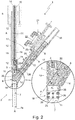
Figure 2 is a side view of the bit-holding head of the automatic screwdriver shown infigure 1 , sectioned along the midplane and with parts removed for clarity; whereas -
Figures 3 and 4 are two partial and enlarged views of the bit-holding head shown infigure 2 , during operation of the automatic screwdriver. - With reference to
figures 1 ,2 ,3 and 4 ,number 1 denotes, as a whole, an autofeed automatic screwdriver which is adapted to screw, into a generic support and in automatic manner, a succession ofscrews 100 preferably made of metal material and preferably of the self-tapping type. - More in detail, the
automatic screwdriver 1 can be advantageously used to screw a succession of screws with a small-sized stem, preferably made of metal material and preferably of the self-tapping type, into a generic board for electronic printed boards or other support. - In other words, the
automatic screwdriver 1 is adapted to receive in input a succession of screws, preferably made of metal material and preferably of the self-tapping type, and to screw in sequence and in automatic manner the single screws into a terminal board for electronic printed boards or other support. - The
automatic screwdriver 1 comprises: a bit-holding head 2 which houses inside itself a knownrotatable screw bit 3 and is adapted to receive, in input, a succession ofscrews 100 that it places in sequence in front of thescrew bit 3, locally substantially coaxial to thesame screw bit 3; and amotor assembly 4, preferably of the electric or pneumatic type, which is preferably rigidly connected/fixed to the bit-holding head 2 via astraight sleeve 5, and is adapted to drive into rotation thescrew bit 3 about its longitudinal axis and, optionally, also to axially move thescrew bit 3 inside the bit-holdinghead 2, so as to bring thescrew bit 3 in abutment against thehead 100 of the screw and then push thescrew 100 out of the bit-holdinghead 2, against the board or other support stationary beneath the bit-holdinghead 2. - With reference to
Figures 1 and2 , the bit-holding head 2 firstly comprises a preferably substantially V- or Y- shaped,outer casing 6 which is preferably made of metal material and is internally provided with a substantially straightmain duct 7 that preferably has a circular cross-section, is open at anend 7a and is dimensioned so as to accommodate thescrew bit 3 and be engaged in axially rotatable and slidable manner by thescrew bit 3 and thesingle screws 100 to be screwed; and with a substantially straightsecondary duct 8 preferably having a circular cross section, which obliquely branches off from themain duct 7 and is dimensioned so as to be able to convey a succession of screws towards themain duct 7, immediately beneath thescrew bit 3. - More in detail, the longitudinal axis B of
secondary duct 8 is inclined with respect to the longitudinal axis A ofmain duct 7 by an angle α preferably lower than 75° and preferably, though not necessarily, ranging between 35° and 45°. - Preferably, the longitudinal axes A and B moreover lie on the midplane of the
outer casing 6. - The
secondary duct 8 furthermore divides themain duct 7 into an upper portion and a lower portion, both substantially straight and coaxial to one another. - The upper portion of
main duct 7 houses thescrew bit 3 with the tip facing the joining/connecting point with thesecondary duct 8. The lower portion ofmain duct 7, on the other hand, ends at theopen end 7a ofmain duct 7 and is adapted to be engaged in axially slidable and rotatable manner by thescrew bit 3 and by thesingle screws 100 to be screwed. - In other words, the
screw bit 3 is housed inside the portion ofmain duct 7 located above the joining/connecting point withsecondary duct 8 and is capable of axially moving inside themain duct 7 to and from the beneath-locatedopen end 7a, going beyond the joining/connecting point withsecondary duct 8. - In the example shown, in particular, the
outer casing 6 is preferably substantially Y-shaped and preferably comprises: acentral block 10 which preferably has a monolithic structure and is substantially V-shaped, with an inclination angle between the two straight branches preferably lower than 75° and preferably ranging between 35° and 45°; and a straighttubular segment 11, preferably with a circular cross section, that projects from thecentral block 10 starting from the bottom vertex of the V, while remaining substantially coaxial to a first straight branch of thecentral block 10. - The axial cavity of the straight
tubular segment 11 is dimensioned so as to be engaged, in axially slidable and axially rotatable manner, by thescrew bit 3 and by thescrews 100 to be screwed; whereas thecentral block 10 is provided with a first straight hole with a circular cross section, that extends in pass-through manner inside the first straight branch of thecentral block 10, while remaining coaxial to the longitudinal axis of the straighttubular segment 11, and is dimensioned to form an extension of the axial cavity of the straighttubular segment 11. - The
central block 10 is moreover provided with a second straight hole with a circular cross section, that branches off obliquely from the first straight hole, extends in pass-through manner inside the second straight branch ofcentral block 10, and is dimensioned so as to be engaged in axially sliding manner by thescrews 100 to be screwed. - The axial cavity of straight
tubular segment 11 and the first straight hole ofcentral block 10 form themain duct 7. - The longitudinal axis of straight
tubular segment 11, therefore, coincides with the longitudinal axis A ofmain duct 7. - The second straight hole of
central block 10, on the other hand, forms thesecondary duct 8. - In other words, the upper portion of
main duct 7 and the entiresecondary duct 8 are preferably entirely contained incentral block 10. - In addition, the joining/connecting point between the
secondary duct 8 andmain duct 7 is preferably located inside thecentral block 10, immediately above the junction with the straighttubular segment 11. - Preferably, the
outer casing 6 furthermore includes a second straighttubular segment 12 preferably having a circular cross section, which projects from thecentral block 10 on the opposite side with respect to the straighttubular segment 11, while remaining substantially coaxial to the longitudinal axis A ofmain duct 7 so as to form an extension ofmain duct 7. - In other words, the straight
tubular segment 12 projects from the distal end of the first straight branch ofcentral block 10, while remaining locally coaxial to the first straight hole ofcentral block 10 and to the straighttubular segment 11. - Preferably, the
central block 10, the straighttubular segment 11 and/or the straighttubular segment 12 is/are made of metal material. - With reference to
Figures 2 ,3 and 4 , the bit-holding head 2 furthermore comprises: a straight bit-holding rod 14 preferably made of metal material, which extends coaxial to the longitudinal axis A ofmain duct 7, is inserted in axially slidable and angularly rotatable manner in theouter casing 6 so as to partially project into the upper portion ofmain duct 7, and is finally integral to thescrew bit 3; and acontrast spring 15 which is interposed between theouter casing 6 and the bit-holding rod 14 and is adapted to elastically counteract the advancing/descent of the bit-holding rod 14 inside themain duct 7, towards theopen end 7a. - More in detail, the bit-
holding rod 14 is firmly fixed on therear shank 16 of thescrew bit 3, and is mechanically connected to themotor assembly 4 so as to be driven into rotation about its longitudinal axis, i.e. around the longitudinal axis A ofmain duct 7. - Preferably, the
screw bit 3 is furthermore firmly fixed onto the lower end of bit-holding rod 14 in manually removable manner. - The
contrast spring 15, on the other hand, is adapted to elastically hold and bring back the ensemble ofscrew bit 3 and bit-holding rod 14 above the joining/connecting point between themain duct 7 and thesecondary duct 8. - Preferably, the
motor assembly 4 is moreover adapted to axially move the bit-holding rod 14 inside theouter casing 6, so as to be able to move thescrew bit 3 along themain duct 7, towards the ductopen end 7a. - In the example shown, in particular, the upper end of bit-
holding rod 14 is preferably provided with a coupling shank (not shown in the figures), which is specifically structured so as to be coupled in rigid manner to themotor assembly 4. - With reference to
Figures 2 ,3 and 4 , in the example shown, in particular, thescrew bit 3 is preferably located inside thecentral block 10 with the tip facing the straighttubular segment 11; whereas the bit-holding rod 14 projects from thecentral block 10 and extends inside the straighttubular segment 12, preferably for the whole length of the sleeve, so as to also jut out from the distal end of the straighttubular segment 12. - In addition, the bit-
holding rod 14 is preferably dimensioned so as to also project into thestraight sleeve 5, up to reach and stably couple with themotor assembly 4. - Preferably, on the other hand, the
contrast spring 15 is fitted on the bit-holding rod 14 so as to have a first end in abutment against thecentral block 10, inside the straighttubular segment 12, and a second end in abutment against a cup, disk or other stop member (not shown in the figures), which is firmly fixed on the bit-holding rod 14, preferably close to the upper end of the same bit-holding rod 14. - More in detail, in the example shown the
contrast spring 15 preferably consists of a helical spring. - With reference to
Figures 1 ,2 ,3 and 4 , the bit-holding head 2 additionally comprises adeflector assembly 17 and, preferably, also a screw-stop device 18. - The
deflector assembly 17 is arranged substantially at the joining/connecting point betweenmain duct 7 andsecondary duct 8, and is adapted to selectively channel thescrews 100 coming out ofsecondary duct 8 towards the lower portion ofmain duct 7, with the tip turned towards theopen end 7a of the samemain duct 7. - The screw-
stop device 18, on the other hand, is arranged along the lower portion ofmain duct 7, preferably immediately downstream of the joining/connecting point withsecondary duct 8, and is adapted to stop eachscrew 100 descending along themain duct 7 towards theopen end 7a, preferably until the moment when thescrew bit 3 reaches and engages the head of thescrew 100.
themotor assembly 4 is therefore adapted to axially move thescrew bit 3 inside themain duct 7 of bit-holdinghead 2, so as to bring thescrew bit 3 in abutment against the head of thescrew 100 stationary at the screw-stop device 18, and then push thescrew 100 along the lower portion ofmain duct 7, towards theopen end 7a. - With particular reference to
Figures 2 ,3 and 4 , thedeflector assembly 17 comprises: amovable shutter 20 preferably with a plate-like structure, which is inserted in slidable manner in theouter casing 6, or rather in thecentral bock 10, so as to be able to move in a guillotine-like manner on a sliding plane P oblique/inclined with respect to the longitudinal axis A ofmain duct 7, between a first operating position (seeFigure 3 ) in which themovable shutter 20 obliquely intersects themain duct 7 at the joining/connecting point with thesecondary duct 8, and a second operating position (seeFigures 2 and4 ) in which themovable shutter 20 does not project into themain duct 7; and a preferably electrically- or pneumatically-operated, movingdevice 21 which is preferably firmly fixed on theouter casing 6, or rather on thecentral block 10, beside themovable shutter 20 and is adapted to move themovable shutter 20 with respect to theouter casing 6, so as to be able to alternatively place themovable shutter 20 in the first or in the second operating position. - More in detail, when it is in the first operating position (see
Figure 3 ), themovable shutter 20 is adapted to form an extension of the upper wall ofsecondary duct 8 that obliquely and preferably entirely crosses themain duct 7 and is capable of deflecting/directing thescrews 100 coming out of the second secondary 8 towards the lower portion ofmain duct 7. - In other words, when it is in the first operating position (see
Figure 3 ), themovable shutter 20 is adapted to form an extension of the upper wall ofsecondary duct 8 that entirely crosses themain duct 7 up to reach and preferably also engage the area of the lateral wall of themain duct 7 which is located on the opposite side of the mouth ofsecondary duct 8. - The
moving device 21, on the other hand, is preferably adapted to automatically move themovable shutter 20 from the first to the second operating position (seeFigures 2 and4 ) when thescrew bit 3 starts its descent along themain duct 7, so as to allow thescrew bit 3 to freely descend in the lower portion ofmain duct 7; and to automatically move themovable shutter 20 from the second to the first operating position (seeFigure 3 ), when thescrew bit 3 returns into the upper portion ofmain duct 7. - Preferably, the
moving device 21 is moreover an electrically- or pneumatically-operated linear actuator adapted to move themovable shutter 20 back and forth in theouter casing 6. - In addition, the
movable shutter 20 is preferably inserted in theouter casing 6 so as to be able to slide on the oblique sliding plane P in a given direction d which is substantially coplanar to the longitudinal axes A and B ofmain duct 7 and ofsecondary duct 8. - With reference to
Figures 2 ,3 and 4 , in particular, the sliding plane P ofmovable shutter 20 is preferably substantially orthogonal to the midplane of theouter casing 6, i.e. to the lying plane ofmain duct 7 and ofsecondary duct 8, and is furthermore inclined with respect to the longitudinal axis A ofmain duct 7 by an angle β preferably lower than 75° and preferably, though not necessarily, ranging between 35° and 45°. - Preferably, the inclination angle β of the sliding plane P of
movable shutter 20 with respect to the longitudinal axis A ofmain duct 7 is lower than or equal to the inclination angle α of the longitudinal axis B ofsecondary duct 8 with respect to the longitudinal axis A ofmain duct 7. - With reference to
Figure 3 , when it is in the first operating position, themovable shutter 20 therefore forms an extension of the upper wall ofsecondary duct 8, which is preferably inclined by some degrees with respect to the longitudinal axis B ofsecondary duct 8, so as to more effectively deflect thescrews 100 coming out ofsecondary duct 8 towards the lower portion ofmain duct 7. - With reference to
Figures 1 ,2 ,3 and 4 , in the example shown, in particular, themovable shutter 20 preferably consists of an oblong plate or blade substantially rectangular in shape, which is preferably made of metal material and is inserted in axially sliding manner inside a slit that is preferably made in theouter casing 6, or rather in thecentral block 10, immediately above the bifurcation of the two diverging branches of the Y. - In addition, the oblong plate is preferably arranged astride the midplane of the
outer casing 6, i.e. astride the lying plane of the longitudinal axes A and B, and preferably extends substantially skimming the branch of theouter casing 6 housing thesecondary duct 8. - With reference to
Figure 2 , on the other hand, the movingdevice 21 is preferably accommodated between the two diverging branches of the V- or Y-shapedouter casing 6 that respectively house themain duct 7 and thesecondary duct 8. - More in detail, the moving
device 21 preferably comprises: a double-actingpneumatic cylinder 22 which is firmly fixed on the branch of theouter casing 6 housing thesecondary duct 8, with themovable stem 23 arranged parallel and integral to an axial end of themovable shutter 20; and optionally also an electro-pneumatic control unit (not shown) which is adapted to control the pressurized air flowing into the two chambers of thepneumatic cylinder 22, so as to be able, on command, to axially move themovable stem 23 and themovable shutter 20 integral thereto. - Preferably, the electro-pneumatic control unit is moreover adapted to synchronize the movements of the
movable shutter 20 with the movements of thescrew bit 3. - With reference to
Figures 2 ,3 and 4 , the screw-stop device 18, on the other hand, is adapted to stop eachsingle screw 100 descending along the lower portion ofmain duct 7, arranging it with the tip of the screw facing theopen end 7a ofmain duct 7 and with the head of the screw facing thescrew bit 3, and is preferably located on thestraight tubular segment 11 close to the junction with thecentral block 10. - Preferably, the screw-
stop device 18 additionally comprises: at least one and preferably a plurality of radiallymovable latches 25 which lie on a same reference plane substantially perpendicular to the longitudinal axis A of straighttubular segment 11, are arranged inside the axial cavity of straighttubular segment 11 spaced apart around the longitudinal axis A of the segment, and are finally inserted in axially sliding manner inside a series of radial seats that are formed in the lateral wall of thestraight tubular segment 11; and anelastic member 26 which is adapted to elastically keep the crown of latches 19 in a locking position (seeFigure 3 ) in which all latches 25 slightly project into thestraight tubular segment 11 so as to prevent the passage of the head of thescrew 100. - More in detail, the
latches 25 preferably are at least three in number (four in the example shown) and are preferably angularly equally spaced around the longitudinal axis A of thestraight tubular segment 11. Preferably, thelatches 25 moreover have a spherical shape, and are preferably finally inserted in axially slidable manner inside a series of radial through holes that are made in the lateral wall of thestraight tubular segment 11, equally angularly spaced around the longitudinal axis A of the segment. - Preferably, the
movable latches 25 furthermore have a diameter that is such as to project out of the lateral wall of thestraight tubular segment 11, on opposite sides of the same wall. - On the other hand, the
elastic member 26 preferably consists of an elastic annular body preferably made of elastomeric material, which is fitted on thestraight tubular segment 11, substantially coplanar to the crown oflatches 25, so as to surround the crown oflatches 25 and be able to elastically push all the latches 19 towards the centre of thestraight tubular segment 11. - More in detail, in the example shown the screw-
stop device 18 preferably comprises two crowns ofmovable latches 25 arranged along thestraight tubular segment 11, one above the other; and twoelastic members 26 each adapted to elastically keep a respective crown ofmovable latches 25 in the locking position. - Finally, with reference to
Figures 1 and2 , the autofeedautomatic screwdriver 1 is preferably moreover provided with an in-feed pipe 30 preferably of flexible type, which is adapted to connect the mouth of thesecondary duct 8 to a screw feeding apparatus (not shown in the figures) which, in turn, is capable of automatically feeding a succession ofscrews 100 at inlet of thesecondary duct 8 of the bit-holdinghead 2 via the in-feed pipe 30. - The screw feeding apparatus is a machinery already widely known in the field of autofeed automatic screwdrivers, and therefore won't be further described.
- General operation of autofeed
automatic screwdriver 1 is easily inferable from the description above, and therefore does not require further explanations. - As regards, on the other hand, the bit-holding
head 2, themovable shutter 20 moves in guillotine-like manner inside theouter casing 6, so as to obliquely extend, when thescrew bit 3 is in the upper portion ofmain duct 7, inside themain duct 7 at the joining/connecting point with thesecondary duct 8, thus to deflect/direct eachscrew 100 coming out ofsecondary duct 8 towards thelower portion 7 ofmain duct 7, with the tip turned towards theopen end 7a of the samemain duct 7. - The advantages connected to the particular structure of the bit-holding
head 2 are remarkable. - The automatic movement of
movable shutter 20 prevents thescrew bit 3 from being subjected to wear. - Furthermore, the autofeed
automatic screwdriver 1 is more compact than the ones currently known and, in addition, does not have movable parts that, during operation, can change the outer shape of the nose or oblong lower section of theautomatic screwdriver 1. - In addition, experimental tests have shown that the
movable shutter 20, by forming an extension of the upper wall ofsecondary duct 8, allows to more effectively deflect/direct thescrews 100 towards the lower portion ofmain duct 7. - Finally the guillotine-like movement of the plate-like
movable shutter 20 along a plane inclined with respect to the longitudinal axis B ofsecondary duct 8 prevents thescrews 100 coming out ofsecondary duct 8 from autonomously moving themovable shutter 20.
Claims (15)
- An autofeed automatic screwdriver (1) comprising: a bit-holding head (2) that houses inside a rotatable screw bit (3) and is adapted to receive at inlet a succession of screws (100) that are arranged in sequence in front of the screw bit (3); and a motor assembly (4) which is adapted to drive into rotation the screw bit (3) about its longitudinal axis;
the bit-holding head (2) comprising: an outer casing (6) internally provided with a substantially straight, main duct (7) open at the bottom and which accommodates said screw bit (3) inside an upper portion of the duct, and a substantially straight, secondary duct (8) that branches off obliquely from the main duct (7) and is dimensioned so as to convey a succession of screws (100) into the main duct (7), below the screw bit (3); and a deflector assembly (17) which is located substantially at the joining/ connecting point between the main duct (7) and the secondary duct (8), and is adapted to channel the screws (100) coming out from the secondary duct (8) towards the lower portion of the main duct (7);
the autofeed automatic screwdriver (1) being characterized in that said deflector assembly (17) comprises: a movable shutter (20) which is inserted in axially slidable manner in the outer casing (6) so that it can move in a guillotine-like manner on a sliding plane (P) inclined with respect to the longitudinal axis (A) of the main duct (7), between a first operating position in which the movable shutter (20) obliquely intersects the main duct (7), at the joining/connecting point with the secondary duct (8), and a second operating position in which the movable shutter (20) does not protrude inside the main duct (7); and a moving device (21) adapted to place the movable shutter (20) alternately in the first or in the second operating position. - Automatic screwdriver according to Claim 1, characterized in that the movable shutter (20) has a plate-like structure.
- Automatic screwdriver according to Claim 1 or 2, characterized in that the sliding plane (P) of the movable shutter (20) is substantially orthogonal to the laying plane of the main (7) and secondary (8) ducts.
- Automatic screwdriver according to Claim 1, 2 or 3, characterized in that the longitudinal axis (B) of the secondary duct (8) is inclined with respect to the longitudinal axis (A) of the main duct (7) by an angle (α) of less than 75°; and/or that the sliding plane (P) of the movable shutter (20) is inclined with respect to the longitudinal axis (A) of the main duct (7) by an angle (β) of less than 75°.
- Automatic screwdriver according to any one of the preceding claims, characterized in that the inclination angle (β) of the sliding plane (P) of the movable shutter (20) with respect to the longitudinal axis (A) of the main duct (7) is lower or equal to the inclination angle (α) of the longitudinal axis (B) of the secondary duct (8) with respect to the longitudinal axis (A) of the main duct (7).
- Automatic screwdriver according to any one of the preceding claims, characterized in that the movable shutter (20), when placed in the first operating position, is adapted to form an extension of the upper wall of the secondary duct (8) that obliquely crosses the main duct (7) .
- Automatic screwdriver according to Claim 6, characterized in that the movable shutter (20), when placed in the first operating position, is adapted to form an extension of the upper wall of the secondary duct (8) which completely crosses the main duct (7) up to reach the lateral wall of the main duct (7) on the opposite side of the mouth of the secondary duct (8).
- Automatic screwdriver according to Claim 6 or 7, characterized in that said extension of the upper wall of the secondary duct (8) is inclined with respect to the longitudinal axis (B) of the secondary duct (8).
- Automatic screwdriver according to any one of the preceding claims, characterized in that the outer casing (6) is substantially V- or Y- shaped.
- Automatic screwdriver according to Claim 9, characterized in that the moving device (21) is accommodated between the two diverging branches of the V-or Y- shaped outer casing (6) that respectively house the main duct (7) and the secondary duct (8).
- Automatic screwdriver according to any one of the preceding claims, characterized in that the moving device (21) is an electrically- or pneumatically- operated, linear actuator.
- Automatic screwdriver according to any one of the preceding claims, characterized in that the bit-holding head (2) furthermore comprises a bit-holding rod (14) which extends coaxial to the longitudinal axis (A) of the main duct (7), is inserted in axially slidable and angularly rotatable manner in the outer casing (6) so as to partly protrude inside the upper portion of the main duct (7), and is finally integral with the screw bit (3); said bit-holding rod (14) being mechanically connected to the motor assembly (4) so as to be driven into rotation about its longitudinal axis.
- Automatic screwdriver according to claim 12, characterized in that the bit-holding head (2) furthermore comprises a contrast spring (15) which is interposed between the outer casing (6) and the bit-holding rod (14), and is adapted to elastically counteract the advancing/ descent of the bit-holding rod (14) within the main duct (7), towards the open end (7a) of the same main duct (7).
- Automatic screwdriver according to any one of the preceding claims, characterized in that the bit-holding head (2) furthermore comprises a screw-stop device (18) which is arranged along the lower portion of the main duct (7), downstream of the joining/connecting point with the secondary duct (8), and is adapted to stop each screw (100) which descends along the main duct (7) towards the open end (7a) .
- Automatic screwdriver according to any one of the preceding claims, characterized in that the motor assembly (4) is adapted to move axially the screw bit (3) within the bit-holding head (2), so as to bring the screw bit (3) in abutment against the head of the screw (100) and then push the screw (100) along the main duct (7), towards the open end (7a).
Priority Applications (1)
| Application Number | Priority Date | Filing Date | Title |
|---|---|---|---|
| PL17210661T PL3342539T3 (en) | 2016-12-27 | 2017-12-27 | Autofeed automatic screwdriver |
Applications Claiming Priority (1)
| Application Number | Priority Date | Filing Date | Title |
|---|---|---|---|
| IT102016000131218A IT201600131218A1 (en) | 2016-12-27 | 2016-12-27 | SELF-POWERED AUTOMATIC SCREWDRIVER |
Publications (2)
| Publication Number | Publication Date |
|---|---|
| EP3342539A1 EP3342539A1 (en) | 2018-07-04 |
| EP3342539B1 true EP3342539B1 (en) | 2020-11-11 |
Family
ID=58701715
Family Applications (1)
| Application Number | Title | Priority Date | Filing Date |
|---|---|---|---|
| EP17210661.9A Active EP3342539B1 (en) | 2016-12-27 | 2017-12-27 | Autofeed automatic screwdriver |
Country Status (4)
| Country | Link |
|---|---|
| EP (1) | EP3342539B1 (en) |
| ES (1) | ES2848557T3 (en) |
| IT (1) | IT201600131218A1 (en) |
| PL (1) | PL3342539T3 (en) |
Families Citing this family (2)
| Publication number | Priority date | Publication date | Assignee | Title |
|---|---|---|---|---|
| DE102018119228A1 (en) | 2018-08-07 | 2020-02-13 | Adunox Gmbh | Auxiliary device for an electrical hand-held device for driving pens into a base |
| CN118848477B (en) * | 2024-09-25 | 2025-01-24 | 合肥晶合集成电路股份有限公司 | A nail removal device |
Family Cites Families (5)
| Publication number | Priority date | Publication date | Assignee | Title |
|---|---|---|---|---|
| US2670770A (en) * | 1950-07-27 | 1954-03-02 | Du Mont Allen B Lab Inc | Screw holding and feeding means for power-operated screw drivers |
| US5897045A (en) * | 1997-09-12 | 1999-04-27 | Illinois Tool Works Inc. | Fastener dispensing apparatus for stand-up fastener driving tool and method therefor |
| DE10305042A1 (en) * | 2003-02-07 | 2004-08-19 | Hilti Ag | Powered driving-in device used as a stand-up tool for fixing/assembling workpieces/construction elements for placing on the floor or for walking on comprises a head part having a rotating connection with the driving-in device |
| CN2813218Y (en) | 2005-06-10 | 2006-09-06 | 杨群根 | Automatic feeding nail electric screwdriver |
| JP5452272B2 (en) * | 2010-02-12 | 2014-03-26 | 株式会社大武ルート工業 | Automatic screw tightening device |
-
2016
- 2016-12-27 IT IT102016000131218A patent/IT201600131218A1/en unknown
-
2017
- 2017-12-27 EP EP17210661.9A patent/EP3342539B1/en active Active
- 2017-12-27 ES ES17210661T patent/ES2848557T3/en active Active
- 2017-12-27 PL PL17210661T patent/PL3342539T3/en unknown
Non-Patent Citations (1)
| Title |
|---|
| None * |
Also Published As
| Publication number | Publication date |
|---|---|
| EP3342539A1 (en) | 2018-07-04 |
| ES2848557T3 (en) | 2021-08-10 |
| PL3342539T3 (en) | 2021-05-31 |
| IT201600131218A1 (en) | 2018-06-27 |
Similar Documents
| Publication | Publication Date | Title |
|---|---|---|
| KR101301682B1 (en) | Automatic screw tightening apparatus | |
| EP3342539A1 (en) | Autofeed automatic screwdriver | |
| US5031489A (en) | Control means for fastener driving device | |
| US11090775B2 (en) | Adaption device for mounting fixture | |
| KR102493588B1 (en) | Gate valve | |
| CN108907057A (en) | Rivet driver | |
| EP3342540B1 (en) | Autofeed automatic screwdriver | |
| US20080099524A1 (en) | Positioning device with actuating switching means for a hand-held setting tool | |
| EP3760395B1 (en) | Gripper actuated by robotic arm | |
| CN107020425B (en) | Electrode wire threading device for electric spark wire etching machine | |
| US6550359B1 (en) | Device and method for driving a part | |
| CN107263064B (en) | Automatic assembly equipment of bleed valve | |
| CN204295400U (en) | Automatic feeding | |
| US5400942A (en) | Automatic fastener feed apparatus and method | |
| US4969582A (en) | Apparatus for feeding an elongated fastener to a fastening tool, especially for feeding a stud in a stud welder | |
| JP6921729B2 (en) | Separation unit | |
| CN112276196B (en) | Iron sheet contact pin shearing and assembling equipment | |
| US10471582B2 (en) | Handheld power tool | |
| US20210094105A1 (en) | Technoscopic instrument | |
| KR20160048536A (en) | Inlet guide vane | |
| CN107932469B (en) | Be used for controlling terminal transmission instrument through narrow passageway | |
| JP2005111559A (en) | Nut feeder | |
| CN108080916B (en) | Extrusion type distributor | |
| EP3231990A1 (en) | Apparatus for machining components of gas turbine engines | |
| KR101155959B1 (en) | Device for providing screw |
Legal Events
| Date | Code | Title | Description |
|---|---|---|---|
| PUAI | Public reference made under article 153(3) epc to a published international application that has entered the european phase |
Free format text: ORIGINAL CODE: 0009012 |
|
| STAA | Information on the status of an ep patent application or granted ep patent |
Free format text: STATUS: THE APPLICATION HAS BEEN PUBLISHED |
|
| AK | Designated contracting states |
Kind code of ref document: A1 Designated state(s): AL AT BE BG CH CY CZ DE DK EE ES FI FR GB GR HR HU IE IS IT LI LT LU LV MC MK MT NL NO PL PT RO RS SE SI SK SM TR |
|
| AX | Request for extension of the european patent |
Extension state: BA ME |
|
| STAA | Information on the status of an ep patent application or granted ep patent |
Free format text: STATUS: REQUEST FOR EXAMINATION WAS MADE |
|
| 17P | Request for examination filed |
Effective date: 20190103 |
|
| RBV | Designated contracting states (corrected) |
Designated state(s): AL AT BE BG CH CY CZ DE DK EE ES FI FR GB GR HR HU IE IS IT LI LT LU LV MC MK MT NL NO PL PT RO RS SE SI SK SM TR |
|
| GRAP | Despatch of communication of intention to grant a patent |
Free format text: ORIGINAL CODE: EPIDOSNIGR1 |
|
| STAA | Information on the status of an ep patent application or granted ep patent |
Free format text: STATUS: GRANT OF PATENT IS INTENDED |
|
| INTG | Intention to grant announced |
Effective date: 20200603 |
|
| RAP1 | Party data changed (applicant data changed or rights of an application transferred) |
Owner name: MARELLI AUTOMOTIVE LIGHTING ITALY S.P.A. |
|
| GRAS | Grant fee paid |
Free format text: ORIGINAL CODE: EPIDOSNIGR3 |
|
| GRAA | (expected) grant |
Free format text: ORIGINAL CODE: 0009210 |
|
| STAA | Information on the status of an ep patent application or granted ep patent |
Free format text: STATUS: THE PATENT HAS BEEN GRANTED |
|
| AK | Designated contracting states |
Kind code of ref document: B1 Designated state(s): AL AT BE BG CH CY CZ DE DK EE ES FI FR GB GR HR HU IE IS IT LI LT LU LV MC MK MT NL NO PL PT RO RS SE SI SK SM TR |
|
| REG | Reference to a national code |
Ref country code: GB Ref legal event code: FG4D |
|
| REG | Reference to a national code |
Ref country code: CH Ref legal event code: EP |
|
| REG | Reference to a national code |
Ref country code: AT Ref legal event code: REF Ref document number: 1333000 Country of ref document: AT Kind code of ref document: T Effective date: 20201115 |
|
| REG | Reference to a national code |
Ref country code: DE Ref legal event code: R096 Ref document number: 602017027291 Country of ref document: DE |
|
| REG | Reference to a national code |
Ref country code: IE Ref legal event code: FG4D |
|
| REG | Reference to a national code |
Ref country code: NL Ref legal event code: MP Effective date: 20201111 |
|
| REG | Reference to a national code |
Ref country code: AT Ref legal event code: MK05 Ref document number: 1333000 Country of ref document: AT Kind code of ref document: T Effective date: 20201111 |
|
| PG25 | Lapsed in a contracting state [announced via postgrant information from national office to epo] |
Ref country code: RS Free format text: LAPSE BECAUSE OF FAILURE TO SUBMIT A TRANSLATION OF THE DESCRIPTION OR TO PAY THE FEE WITHIN THE PRESCRIBED TIME-LIMIT Effective date: 20201111 Ref country code: PT Free format text: LAPSE BECAUSE OF FAILURE TO SUBMIT A TRANSLATION OF THE DESCRIPTION OR TO PAY THE FEE WITHIN THE PRESCRIBED TIME-LIMIT Effective date: 20210311 Ref country code: NO Free format text: LAPSE BECAUSE OF FAILURE TO SUBMIT A TRANSLATION OF THE DESCRIPTION OR TO PAY THE FEE WITHIN THE PRESCRIBED TIME-LIMIT Effective date: 20210211 Ref country code: FI Free format text: LAPSE BECAUSE OF FAILURE TO SUBMIT A TRANSLATION OF THE DESCRIPTION OR TO PAY THE FEE WITHIN THE PRESCRIBED TIME-LIMIT Effective date: 20201111 Ref country code: GR Free format text: LAPSE BECAUSE OF FAILURE TO SUBMIT A TRANSLATION OF THE DESCRIPTION OR TO PAY THE FEE WITHIN THE PRESCRIBED TIME-LIMIT Effective date: 20210212 |
|
| PG25 | Lapsed in a contracting state [announced via postgrant information from national office to epo] |
Ref country code: BG Free format text: LAPSE BECAUSE OF FAILURE TO SUBMIT A TRANSLATION OF THE DESCRIPTION OR TO PAY THE FEE WITHIN THE PRESCRIBED TIME-LIMIT Effective date: 20210211 Ref country code: LV Free format text: LAPSE BECAUSE OF FAILURE TO SUBMIT A TRANSLATION OF THE DESCRIPTION OR TO PAY THE FEE WITHIN THE PRESCRIBED TIME-LIMIT Effective date: 20201111 Ref country code: IS Free format text: LAPSE BECAUSE OF FAILURE TO SUBMIT A TRANSLATION OF THE DESCRIPTION OR TO PAY THE FEE WITHIN THE PRESCRIBED TIME-LIMIT Effective date: 20210311 Ref country code: AT Free format text: LAPSE BECAUSE OF FAILURE TO SUBMIT A TRANSLATION OF THE DESCRIPTION OR TO PAY THE FEE WITHIN THE PRESCRIBED TIME-LIMIT Effective date: 20201111 Ref country code: SE Free format text: LAPSE BECAUSE OF FAILURE TO SUBMIT A TRANSLATION OF THE DESCRIPTION OR TO PAY THE FEE WITHIN THE PRESCRIBED TIME-LIMIT Effective date: 20201111 |
|
| REG | Reference to a national code |
Ref country code: LT Ref legal event code: MG9D |
|
| PG25 | Lapsed in a contracting state [announced via postgrant information from national office to epo] |
Ref country code: HR Free format text: LAPSE BECAUSE OF FAILURE TO SUBMIT A TRANSLATION OF THE DESCRIPTION OR TO PAY THE FEE WITHIN THE PRESCRIBED TIME-LIMIT Effective date: 20201111 |
|
| PG25 | Lapsed in a contracting state [announced via postgrant information from national office to epo] |
Ref country code: SK Free format text: LAPSE BECAUSE OF FAILURE TO SUBMIT A TRANSLATION OF THE DESCRIPTION OR TO PAY THE FEE WITHIN THE PRESCRIBED TIME-LIMIT Effective date: 20201111 Ref country code: RO Free format text: LAPSE BECAUSE OF FAILURE TO SUBMIT A TRANSLATION OF THE DESCRIPTION OR TO PAY THE FEE WITHIN THE PRESCRIBED TIME-LIMIT Effective date: 20201111 Ref country code: SM Free format text: LAPSE BECAUSE OF FAILURE TO SUBMIT A TRANSLATION OF THE DESCRIPTION OR TO PAY THE FEE WITHIN THE PRESCRIBED TIME-LIMIT Effective date: 20201111 Ref country code: EE Free format text: LAPSE BECAUSE OF FAILURE TO SUBMIT A TRANSLATION OF THE DESCRIPTION OR TO PAY THE FEE WITHIN THE PRESCRIBED TIME-LIMIT Effective date: 20201111 Ref country code: LT Free format text: LAPSE BECAUSE OF FAILURE TO SUBMIT A TRANSLATION OF THE DESCRIPTION OR TO PAY THE FEE WITHIN THE PRESCRIBED TIME-LIMIT Effective date: 20201111 |
|
| REG | Reference to a national code |
Ref country code: CH Ref legal event code: PL |
|
| REG | Reference to a national code |
Ref country code: ES Ref legal event code: FG2A Ref document number: 2848557 Country of ref document: ES Kind code of ref document: T3 Effective date: 20210810 |
|
| REG | Reference to a national code |
Ref country code: DE Ref legal event code: R097 Ref document number: 602017027291 Country of ref document: DE |
|
| PG25 | Lapsed in a contracting state [announced via postgrant information from national office to epo] |
Ref country code: DK Free format text: LAPSE BECAUSE OF FAILURE TO SUBMIT A TRANSLATION OF THE DESCRIPTION OR TO PAY THE FEE WITHIN THE PRESCRIBED TIME-LIMIT Effective date: 20201111 Ref country code: MC Free format text: LAPSE BECAUSE OF FAILURE TO SUBMIT A TRANSLATION OF THE DESCRIPTION OR TO PAY THE FEE WITHIN THE PRESCRIBED TIME-LIMIT Effective date: 20201111 |
|
| REG | Reference to a national code |
Ref country code: BE Ref legal event code: MM Effective date: 20201231 |
|
| PLBE | No opposition filed within time limit |
Free format text: ORIGINAL CODE: 0009261 |
|
| STAA | Information on the status of an ep patent application or granted ep patent |
Free format text: STATUS: NO OPPOSITION FILED WITHIN TIME LIMIT |
|
| 26N | No opposition filed |
Effective date: 20210812 |
|
| PG25 | Lapsed in a contracting state [announced via postgrant information from national office to epo] |
Ref country code: LU Free format text: LAPSE BECAUSE OF NON-PAYMENT OF DUE FEES Effective date: 20201227 Ref country code: NL Free format text: LAPSE BECAUSE OF FAILURE TO SUBMIT A TRANSLATION OF THE DESCRIPTION OR TO PAY THE FEE WITHIN THE PRESCRIBED TIME-LIMIT Effective date: 20201111 Ref country code: AL Free format text: LAPSE BECAUSE OF FAILURE TO SUBMIT A TRANSLATION OF THE DESCRIPTION OR TO PAY THE FEE WITHIN THE PRESCRIBED TIME-LIMIT Effective date: 20201111 Ref country code: IE Free format text: LAPSE BECAUSE OF NON-PAYMENT OF DUE FEES Effective date: 20201227 |
|
| PG25 | Lapsed in a contracting state [announced via postgrant information from national office to epo] |
Ref country code: SI Free format text: LAPSE BECAUSE OF FAILURE TO SUBMIT A TRANSLATION OF THE DESCRIPTION OR TO PAY THE FEE WITHIN THE PRESCRIBED TIME-LIMIT Effective date: 20201111 Ref country code: CH Free format text: LAPSE BECAUSE OF NON-PAYMENT OF DUE FEES Effective date: 20201231 Ref country code: LI Free format text: LAPSE BECAUSE OF NON-PAYMENT OF DUE FEES Effective date: 20201231 |
|
| PG25 | Lapsed in a contracting state [announced via postgrant information from national office to epo] |
Ref country code: IS Free format text: LAPSE BECAUSE OF FAILURE TO SUBMIT A TRANSLATION OF THE DESCRIPTION OR TO PAY THE FEE WITHIN THE PRESCRIBED TIME-LIMIT Effective date: 20210311 Ref country code: MT Free format text: LAPSE BECAUSE OF FAILURE TO SUBMIT A TRANSLATION OF THE DESCRIPTION OR TO PAY THE FEE WITHIN THE PRESCRIBED TIME-LIMIT Effective date: 20201111 Ref country code: CY Free format text: LAPSE BECAUSE OF FAILURE TO SUBMIT A TRANSLATION OF THE DESCRIPTION OR TO PAY THE FEE WITHIN THE PRESCRIBED TIME-LIMIT Effective date: 20201111 |
|
| PG25 | Lapsed in a contracting state [announced via postgrant information from national office to epo] |
Ref country code: MK Free format text: LAPSE BECAUSE OF FAILURE TO SUBMIT A TRANSLATION OF THE DESCRIPTION OR TO PAY THE FEE WITHIN THE PRESCRIBED TIME-LIMIT Effective date: 20201111 |
|
| PG25 | Lapsed in a contracting state [announced via postgrant information from national office to epo] |
Ref country code: BE Free format text: LAPSE BECAUSE OF NON-PAYMENT OF DUE FEES Effective date: 20201231 |
|
| PGFP | Annual fee paid to national office [announced via postgrant information from national office to epo] |
Ref country code: PL Payment date: 20241122 Year of fee payment: 8 |
|
| PGFP | Annual fee paid to national office [announced via postgrant information from national office to epo] |
Ref country code: GB Payment date: 20241122 Year of fee payment: 8 |
|
| PGFP | Annual fee paid to national office [announced via postgrant information from national office to epo] |
Ref country code: CZ Payment date: 20241127 Year of fee payment: 8 |
|
| PGFP | Annual fee paid to national office [announced via postgrant information from national office to epo] |
Ref country code: TR Payment date: 20241127 Year of fee payment: 8 |
|
| PGFP | Annual fee paid to national office [announced via postgrant information from national office to epo] |
Ref country code: ES Payment date: 20250102 Year of fee payment: 8 |
|
| PGFP | Annual fee paid to national office [announced via postgrant information from national office to epo] |
Ref country code: DE Payment date: 20251126 Year of fee payment: 9 |
|
| PGFP | Annual fee paid to national office [announced via postgrant information from national office to epo] |
Ref country code: IT Payment date: 20251119 Year of fee payment: 9 |
|
| PGFP | Annual fee paid to national office [announced via postgrant information from national office to epo] |
Ref country code: FR Payment date: 20251120 Year of fee payment: 9 |