EP3342500A1 - Molding device - Google Patents
Molding device Download PDFInfo
- Publication number
- EP3342500A1 EP3342500A1 EP16841724.4A EP16841724A EP3342500A1 EP 3342500 A1 EP3342500 A1 EP 3342500A1 EP 16841724 A EP16841724 A EP 16841724A EP 3342500 A1 EP3342500 A1 EP 3342500A1
- Authority
- EP
- European Patent Office
- Prior art keywords
- die
- metal pipe
- pipe material
- lower die
- forming device
- Prior art date
- Legal status (The legal status is an assumption and is not a legal conclusion. Google has not performed a legal analysis and makes no representation as to the accuracy of the status listed.)
- Granted
Links
- 238000000465 moulding Methods 0.000 title 1
- 239000002184 metal Substances 0.000 claims abstract description 118
- 239000000463 material Substances 0.000 claims abstract description 106
- 230000005415 magnetization Effects 0.000 claims description 44
- 230000004907 flux Effects 0.000 claims description 30
- 230000007246 mechanism Effects 0.000 description 37
- 238000010438 heat treatment Methods 0.000 description 25
- 238000000071 blow moulding Methods 0.000 description 22
- 238000010586 diagram Methods 0.000 description 17
- 238000001816 cooling Methods 0.000 description 16
- XLYOFNOQVPJJNP-UHFFFAOYSA-N water Substances O XLYOFNOQVPJJNP-UHFFFAOYSA-N 0.000 description 16
- 238000003825 pressing Methods 0.000 description 8
- 238000007789 sealing Methods 0.000 description 7
- 229910000734 martensite Inorganic materials 0.000 description 6
- 230000009466 transformation Effects 0.000 description 5
- 239000000498 cooling water Substances 0.000 description 4
- 239000012530 fluid Substances 0.000 description 4
- 230000002093 peripheral effect Effects 0.000 description 4
- 238000003860 storage Methods 0.000 description 4
- 229910000831 Steel Inorganic materials 0.000 description 3
- 230000008859 change Effects 0.000 description 3
- 230000000694 effects Effects 0.000 description 3
- 238000004519 manufacturing process Methods 0.000 description 3
- 238000000034 method Methods 0.000 description 3
- 239000010959 steel Substances 0.000 description 3
- 229910001566 austenite Inorganic materials 0.000 description 2
- 239000002826 coolant Substances 0.000 description 2
- 238000010791 quenching Methods 0.000 description 2
- 230000000171 quenching effect Effects 0.000 description 2
- WSWCOQWTEOXDQX-MQQKCMAXSA-M (E,E)-sorbate Chemical compound C\C=C\C=C\C([O-])=O WSWCOQWTEOXDQX-MQQKCMAXSA-M 0.000 description 1
- 238000005452 bending Methods 0.000 description 1
- 230000000903 blocking effect Effects 0.000 description 1
- 239000003638 chemical reducing agent Substances 0.000 description 1
- 230000005489 elastic deformation Effects 0.000 description 1
- 239000012634 fragment Substances 0.000 description 1
- 230000006872 improvement Effects 0.000 description 1
- 238000002347 injection Methods 0.000 description 1
- 239000007924 injection Substances 0.000 description 1
- 238000005259 measurement Methods 0.000 description 1
- 230000003287 optical effect Effects 0.000 description 1
- 230000005855 radiation Effects 0.000 description 1
- 239000000243 solution Substances 0.000 description 1
- 229940075554 sorbate Drugs 0.000 description 1
- 239000002436 steel type Substances 0.000 description 1
- 238000005496 tempering Methods 0.000 description 1
Images


Classifications
-
- B—PERFORMING OPERATIONS; TRANSPORTING
- B21—MECHANICAL METAL-WORKING WITHOUT ESSENTIALLY REMOVING MATERIAL; PUNCHING METAL
- B21D—WORKING OR PROCESSING OF SHEET METAL OR METAL TUBES, RODS OR PROFILES WITHOUT ESSENTIALLY REMOVING MATERIAL; PUNCHING METAL
- B21D26/00—Shaping without cutting otherwise than using rigid devices or tools or yieldable or resilient pads, i.e. applying fluid pressure or magnetic forces
- B21D26/02—Shaping without cutting otherwise than using rigid devices or tools or yieldable or resilient pads, i.e. applying fluid pressure or magnetic forces by applying fluid pressure
- B21D26/033—Deforming tubular bodies
- B21D26/047—Mould construction
-
- B—PERFORMING OPERATIONS; TRANSPORTING
- B21—MECHANICAL METAL-WORKING WITHOUT ESSENTIALLY REMOVING MATERIAL; PUNCHING METAL
- B21D—WORKING OR PROCESSING OF SHEET METAL OR METAL TUBES, RODS OR PROFILES WITHOUT ESSENTIALLY REMOVING MATERIAL; PUNCHING METAL
- B21D26/00—Shaping without cutting otherwise than using rigid devices or tools or yieldable or resilient pads, i.e. applying fluid pressure or magnetic forces
- B21D26/02—Shaping without cutting otherwise than using rigid devices or tools or yieldable or resilient pads, i.e. applying fluid pressure or magnetic forces by applying fluid pressure
- B21D26/033—Deforming tubular bodies
Definitions
- the present invention relates to a forming device.
- a forming device that forms a metal pipe by blow forming after closing a die has been known.
- a forming device disclosed in PTL 1 is provided with a die and a gas supply part that supplies a gas into a metal pipe material.
- a metal pipe material is disposed in the die, and in a state in which the die is closed, the metal pipe material is expanded by a gas supplied from the gas supply part to form the metal pipe material into a shape corresponding to a shape of the die.
- the metal pipe material before the expansion of the metal pipe material, the metal pipe material is held by electrodes and heated by energization of the electrodes.
- the die or a member around the die may be magnetized in a case where the metal pipe material is heated by energization of the electrodes.
- an electromagnetic force may act on the magnetized die such that the die is moved in a sliding direction that is a moving direction of the die.
- electrical leakage may be caused via the die and the device may be damaged.
- the invention is contrived to solve the problem, and an object of an aspect of the invention is to provide a forming device in which stability can be improved.
- the die movement suppressing part suppresses the movement of the die by an electromagnetic force at least when the energization to the metal pipe material is performed by the electrode. That is, even in a case where a mechanism that heats the metal pipe material by energization of the electrode is provided, it is possible to suppress the movement of the die toward the metal pipe material by an electromagnetic force. Accordingly, stability can be improved.
- the die movement suppressing part may be provided with a fixing part that mechanically fixes the lower die at least when the energization to the metal pipe material is performed by the electrode.
- the fixing part mechanically fixes the lower die that is easily moved by an electromagnetic force, the movement of the lower die can be securely suppressed.
- the fixing part may be provided with a pin that is inserted into a side surface of the lower die at least when the energization to the metal pipe material is performed by the electrode.
- the die movement suppressing part may be provided with a die magnetization suppressing part that suppresses the movement of the die by an electromagnetic force by suppressing the magnetization of the die.
- a die magnetization suppressing part that suppresses the movement of the die by an electromagnetic force by suppressing the magnetization of the die.
- the die magnetization suppressing part may be provided with a switching part that switches the direction of a DC current that is supplied to the electrode.
- the magnetization of the die can be cancelled by allowing a DC current in an opposite direction to flow to the electrode.
- the die magnetization suppressing part may be provided with a coil surrounding the die.
- the magnetization of the die can be cancelled with a magnetic flux generated by the coil.
- the coil may be provided to surround each of the upper die and the lower die.
- the magnetization of the die can be efficiently cancelled by providing the coil in both of the upper die and the lower die.
- the upper die may be supported by an upper die holder
- the lower die may be supported by a lower die holder
- the die magnetization suppressing part may be provided with a magnetic flux loop forming part including a protrusion extending from one of the upper die holder and the lower die holder toward the other at a position adjacent to the die. Accordingly, the concentration of a magnetic flux loop in the lower die and the upper die can be suppressed, and thus promotion of the magnetization of the die can be suppressed.
- a protrusion provided on the outer surface side of at least one of the upper die holder and the lower die holder may form a leakage magnetic field suppressing part. Accordingly, it is possible to prevent a leakage magnetic field from affecting an external device with a simple configuration in which the die holder is provided with the protrusion.
- the stability of the forming device can be improved.
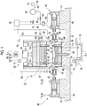
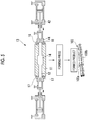
- Fig. 1 is a schematic diagram of a configuration of a forming device
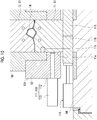
- Fig. 2 is a transverse sectional view of a blow forming die and upper die and lower die holding parts, taken along the line II-II of Fig. 1 .
- a forming device 10 that forms a metal pipe 100 (see Fig.
- a blow forming die 13 composed of a pair of a lower die 11 and an upper die 12, a lower die holding part 91 for holding the lower die 11, an upper die holding part 92 for holding the upper die 12, a driving mechanism 80 that moves at least one of the lower die holding part 91 holding the lower die 11 and the upper die holding part 92 holding the upper die 12 (here, upper die holding part 92), a pipe holding mechanism 30 that holds a metal pipe material 14 shown by the virtual line between the lower die 11 and the upper die 12, a heating mechanism 50 that energizes the metal pipe material 14 held by the pipe holding mechanism 30 to heat the metal pipe material, a gas supply part 60 for supplying a high-pressure gas (gas) into the metal pipe material 14 held and heated between the lower die 11 and the upper die 12, a pair of gas supply mechanisms (gas supply part) 40 for supplying a gas into the metal pipe material 14 held by the pipe holding mechanism 30 from the gas supply part 60, and a water circulation mechanism 72 that forcibly cools the blow forming die 13
- the forming device 10 is provided with a lower die driving mechanism 90 that drives the lower die 11 in a vertical direction.
- the forming device 10 is provided with a controller 70 that controls driving of the driving mechanism 80, driving of the lower die driving mechanism 90, driving of the pipe holding mechanism 30, driving of the heating mechanism 50, and gas supply of the gas supply part 60.
- the lower die 11 is fixed to a large base 15 via the lower die holding part 91.
- the lower die 11 is composed of a large steel block and is provided with a recessed part 16 in an upper surface thereof (a parting surface from the upper die 12).
- the lower die holding part 91 holding the lower die 11 is provided with a first lower die holder 93 holding the lower die 11, a second lower die holder 94 holding the first lower die holder 93, and a lower die base plate 95 holding the second lower die holder 94, that are laminated in order from the top.
- the lower die base plate 95 is fixed to the base 15.
- lengths of the first lower die holder 93 and the second lower die holder 94 in an axial direction are almost the same as that of the lower die 11 in the axial direction.
- An electrode storage space 11a is provided near each of right and left ends (right and left ends in Fig. 1 ) of the lower die 11, and a first electrode 17 and a second electrode 18 that are configured to advance or retreat in a vertical direction by an actuator (not shown) are provided in the electrode storage spaces 11a.
- Recessed grooves 17a and 18a having a semi-arc shape corresponding to an outer peripheral surface on the lower side of the metal pipe material 14 are formed in upper surfaces of the first electrode 17 and the second electrode 18, respectively (see Fig. 3C ).
- the metal pipe material 14 can be placed to be well fitted in the recessed grooves 17a and 18a.
- tapered recessed surfaces 17b and 18b are formed such that the vicinities thereof are recessed at an angle into a tapered shape toward the recessed grooves 17a and 18a, respectively.
- the lower die 11 has a cooling water passage 19 formed therein.
- a lower die driving mechanism 90 extending in the vertical direction through the second lower die holder 94 and the lower die base plate 95 is provided.
- the lower die driving mechanism 90 is provided with a support part 101 supporting the lower surface of the lower die 11 and an axial part 102 extending downward from the support part 101.
- the lower end side of the axial part 102 is connected to a driving part (not shown).
- the pair of first and second electrodes 17 and 18 positioned in the lower die 11 constitute the pipe holding mechanism 30, and can elevatably support the metal pipe material 14 between the upper die 12 and the lower die 11.
- the forming device 10 is provided with a thermocouple (not shown) for measuring the temperature of the metal pipe material 14.
- the thermocouple may be inserted from the side of the die 13.
- the thermocouple is just an example of the temperature measuring unit, and a non-contact temperature sensor such as a radiation thermometer or an optical thermometer may be provided.
- a configuration without the temperature measuring unit may also be employed if the correlation between the energization time and the temperature can be obtained.
- the upper die 12 is a large steel block that is provided with a recessed part 24 in a lower surface thereof (a parting surface from the lower die 11) and a cooling water passage 25 built therein.
- the upper die holding part 92 holding the upper die 12 is provided with a first upper die holder 96 holding the upper die 12, a second upper die holder 97 holding the first upper die holder 96, and an upper die base plate 98 holding the second upper die holder 97, that are laminated in order from the bottom.
- the upper die base plate 98 is fixed to a slide 82. As shown in Fig.
- lengths of the first upper die holder 96 and the second upper die holder 97 in an axial direction are almost the same as that of the upper die 12 in the axial direction.
- the slide 82 to which the upper die holding part 92 is fixed is suspended by a pressing cylinder 26, and is guided by a guide cylinder 27 so as not to laterally vibrate.
- an electrode storage space 12a is provided near each of right and left ends (right and left ends in Fig. 1 ) of the upper die 12, and a first electrode 17 and a second electrode 18 that are configured to advance or retreat in the vertical direction by an actuator (not shown) are provided in the electrode storage spaces 12a.
- Recessed grooves 17a and 18a having a semi-arc shape corresponding to an outer peripheral surface on the upper side of the metal pipe material 14 are formed in lower surfaces of the first and second electrodes 17 and 18, respectively (see Fig. 3C ), and the metal pipe material 14 can be well fitted in the recessed grooves 17a and 18a.
- tapered recessed surfaces 17b and 18b are formed such that the vicinities thereof are recessed at an angle into a tapered shape toward the recessed grooves 17a and 18a, respectively. Accordingly, in a case where the pair of first and second electrodes 17 and 18 positioned in the upper die 12 also constitute the pipe holding mechanism 30 and the metal pipe material 14 is sandwiched between the upper and lower pairs of first and second electrodes 17 and 18 from the vertical direction, the metal pipe material 14 can be surrounded such that the outer periphery thereof firmly adheres well over the whole periphery.
- the fixing parts of the respective actuators moving the first electrode 17 and the second electrode 18 corresponding to a moving part up and down are held and fixed to the lower die holding part 91 and the upper die holding part 92, respectively.
- the driving mechanism 80 is provided with a slide 82 that moves the upper die 12 and the upper die holding part 92 so as to combine the upper die 12 and the lower die 11 together, a driving part 81 that generates a driving force for moving the slide 82, and a servo motor 83 that controls a fluid amount with respect to the driving part 81.
- the driving part 81 is composed of a fluid supply part that supplies a fluid (an operating oil in a case where a hydraulic cylinder is employed as the pressing cylinder 26) for driving the pressing cylinder 26 to the pressing cylinder 26.
- the controller 70 can control the movement of the slide 82 by controlling the amount of the fluid to be supplied to the pressing cylinder 26 by controlling the servo motor 83 of the driving part 81.
- the driving part 81 is not limited to a part that applies a driving force to the slide 82 via the pressing cylinder 26 as described above.
- the driving part may be mechanically connected to the slide 82 to directly or indirectly apply a driving force generated by the servo motor 83 to the slide 82.
- a driving mechanism having an eccentric shaft, a driving source (for example, a servo motor and a reducer) that applies a rotating force for rotating the eccentric shaft, and a converter (for example, a connecting rod or an eccentric sleeve) that converts the rotational movement of the eccentric shaft into the linear movement to move the slide may be employed.
- the driving part 81 may not have the servo motor 83.
- an upper end surface of the lower die 11 and a lower end surface of the upper die 12 are uneven.
- the recessed part 16 with a rectangular cross-sectional shape is formed at the center of the upper end surface of the lower die 11
- the recessed part 24 with a rectangular cross-sectional shape is formed at the center of the lower end surface of the upper die 12 to be opposed to the recessed part 16 of the lower die 11.
- the first lower die holder 93 that constitutes the lower die holding part 91 and holds the lower die 11 is provided with a recessed part 93a with a rectangular cross-sectional shape at a center of an upper end surface 93e of the rectangular parallelepiped.
- the lower die 11 is held such that the substantially lower half thereof is fitted into a gap 93c provided at the center of a bottom surface 93d of the recessed part 93a and dividing the first lower die holder 93.
- Spaces S1 and S2 are respectively provided between protrusions 93b at both sides that form the recessed part 93a of the first lower die holder 93 and side surfaces of the substantially upper half of the lower die 11 that protrude higher than the bottom surface 93d of the first lower die holder 93, and protrusions 96b of the first upper die holder 96 to be described later proceed into the spaces S1 and S2 in a case where the blow forming die 13 is closed.
- the first upper die holder 96 that constitutes the upper die holding part 92 and holds the upper die 12 is formed into a stepped block shape, in which the rectangular parallelepiped becomes smaller downward in a stepwise manner, by forming two steps toward the lower side from the upper side at both sides of the rectangular parallelepiped.
- a recessed part 96a with a rectangular cross-sectional shape is formed at a center of a lower end surface 96d of the first upper die holder 96, and the upper die 12 is held to be housed in the recessed part 96a. Accordingly, inner surfaces of the protrusions 96b at both sides that form the recessed part 96a of the first upper die holder 96 are brought into contact with the side surfaces of the upper die 12.
- the protrusions 96b protrude downward from the lower end surface of the upper die 12 by a predetermined length, and respectively proceed into the spaces S1 and S2 of the first lower die holder 93 in a case where the blow forming die 13 is closed.
- the lower end surface (tip end surface) 96d of the protrusion 96b of the first upper die holder 96 is brought into contact with the bottom surface 93d of the recessed part 93a of the first lower die holder 93, and step surfaces 96e that form the protrusions 96b at both sides of the protrusions 96b of the first upper die holder 96 and are positioned above the protrusions 96b are brought into contact with the upper end surfaces 93e of the protrusions 93b of the first lower die holder 93.
- the heating mechanism 50 has the first and second electrodes 17 and 18, a power supply 51, conductive wires 52 that extend from the power supply 51 and are connected to the first and second electrodes 17 and 18, and a switch 53 that is provided in the conductive wire 52.
- the controller 70 controls the heating mechanism 50, and thus the metal pipe material 14 can be heated to a quenching temperature (equal to or higher than an AC3 transformation temperature).
- Each of the pair of gas supply mechanisms 40 has a cylinder unit 42, a cylinder rod 43 that advances or retreats in accordance with the operation of the cylinder unit 42, and a sealing member 44 that is connected to a tip end of the cylinder rod 43 on the side of the pipe holding mechanism 30.
- the cylinder unit 42 is placed and fixed on the base 15 via a block 41.
- a tapered surface 45 is formed at a tip end of the sealing member 44 so as to be tapered.
- the tapered surfaces are formed into such a shape as to be well fitted in and brought into contact with the tapered recessed surfaces 17b and 18b of the first and second electrodes 17 and 18 (see Figs. 3A to 3C ).
- the sealing member 44 is provided with a gas passage 46 that extends from the cylinder unit 42 toward the tip end, specifically, through which a high-pressure gas supplied from the gas supply part 60 flows as shown in Figs. 3A and 3B .
- the gas supply part 60 includes a high-pressure gas supply 61, an accumulator 62 that stores a gas supplied by the high-pressure gas supply 61, a first tube 63 that extends from the accumulator 62 to the cylinder unit 42 of the gas supply mechanism 40, a pressure control valve 64 and a switching valve 65 that are provided in the first tube 63, a second tube 67 that extends from the accumulator 62 to the gas passage 46 formed in the sealing member 44, and a pressure control valve 68 and a check valve 69 that are provided in the second tube 67.
- the pressure control valve 64 functions to supply, to the cylinder unit 42, a gas having an operation pressure adapted for the pressing force of the sealing member 44 with respect to the metal pipe material 14.
- the check valve 69 functions to prevent the high-pressure gas from flowing backward in the second tube 67.
- the controller 70 controls the pressure control valve 68 of the gas supply part 60, and thus a gas having a desired operation pressure can be supplied into the metal pipe material 14.
- the controller 70 acquires temperature information from the thermocouple (not shown), and controls the pressing cylinder 26 and the switch 53.
- the water circulation mechanism 72 includes a water tank 73 that stores water, a water pump 74 that draws up and pressurizes the water stored in the water tank 73 to send the water to the cooling water passage 19 of the lower die 11 and the cooling water passage 25 of the upper die 12, and a pipe 75.
- a cooling tower that lowers the water temperature or a filter that purifies the water may be provided in the pipe 75.
- a metal pipe material 14 that is a quenchable steel type is prepared.
- the metal pipe material 14 is placed (injected) on the first and second electrodes 17 and 18 provided in the lower die 11 using, for example, a robot arm or the like. Since the first and second electrodes 17 and 18 have the recessed grooves 17a and 18a, respectively, the metal pipe material 14 is positioned by the recessed grooves 17a and 18a.
- the controller 70 controls the pipe holding mechanism 30 to hold the metal pipe material 14 by the pipe holding mechanism 30. Specifically, as in Fig.
- an actuator (not shown) that allows the first and second electrodes 17 and 18 to advance or retreat is operated such that the first and second electrodes 17 and 18 positioned on the upper and lower sides, respectively, are brought closer to and into contact with each other. Due to this contact, both of the end parts of the metal pipe material 14 are sandwiched between the first and second electrodes 17 and 18 from the upper and lower sides. In addition, due to the presence of the recessed grooves 17a and 18a formed in the first and second electrodes 17 and 18, the metal pipe material 14 is sandwiched so as to firmly adhere over the whole periphery thereof.
- the controller 70 controls the heating mechanism 50 to heat the metal pipe material 14. Specifically, the controller 70 turns on the switch 53 of the heating mechanism 50. In that case, electric power is supplied from the power supply 51 to the metal pipe material 14, and the metal pipe material 14 produces heat (Joule heat) due to the resistance present in the metal pipe material 14. In this case, the measurement value of the thermocouple is always monitored, and based on the results thereof, the energization is controlled and the cylinder unit 42 of the gas supply mechanism 40 is operated. Accordingly, both ends of the metal pipe material 14 are sealed by the sealing member 44 (see also Figs. 3A to 3C ) .
- Fig. 6 is a diagram showing operations of the blow forming die and the first upper die holder and a change in shape of the metal pipe material.
- Fig. 7 is a diagram following Fig. 6 .
- Fig. 8 is a diagram following Fig. 7 .
- the blow forming die 13 is closed with respect to the metal pipe material 14 after heating.
- the protrusions 96b of the first upper die holder 96 proceed into the spaces S1 and S2 of the first lower die holder 93, and between the recessed part 16 of the lower die 11 and the recessed part 24 of the upper die 12, a main cavity part MC with a substantially rectangular cross-sectional shape is formed that is a gap for forming a pipe part (main body part) 100a.
- sub-cavity parts SC1 and SC2 that communicate with the main cavity part MC and are gaps for forming flange parts 100b and 100c are respectively formed at both sides of the main cavity part MC between the upper end surface of the lower die 11 and the lower end surface of the upper die 12.
- the sub-cavity parts SC1 and SC2 between the upper end surface of the lower die 11 and the lower end surface of the upper die 12 extend to be opened to the outside of the die.
- the sub-cavity parts SC1 and SC2 are blocked from the outside by inner surfaces 96f of the protrusions 96b of the first upper die holder 96.
- the protrusions 96b of the first upper die holder 96, blocking the sub-cavity parts SC1 and SC2 from the outside of the die, are operated such that foreign matter such as fragments generated when, for example, the metal pipe bursts in the die is prevented from advancing out of the die through the sub-cavity parts SC1 and SC2 and from being discharged.
- the first upper die holder 96 having the protrusions 96b also functions as a shielding member.
- the metal pipe material 14 is fitted in the main cavity part MC, and in a state in which the metal pipe material is in contact with the bottom surface of the recessed part 16 of the lower die 11 and the bottom surface of the recessed part 24 of the upper die 12, a high-pressure gas is supplied into the metal pipe material 14 by the gas supply part 60 to start blow forming.
- the metal pipe material 14 is softened by being heated at a high temperature (about 950°C), the gas supplied into the metal pipe material 14 is thermally expanded. Therefore, for example, with the use of compressed air as a gas to be supplied, the metal pipe material 14 at 950°C can be easily expanded by thermally expanded compressed air.
- blow forming die 13 is further closed, and as shown in Fig. 7 , the main cavity part MC and the sub-cavity parts SC1 and SC2 are further narrowed between the lower die 11 and the upper die 12.
- the metal pipe material 14 is expanded in the main cavity part MC so as to follow the recessed parts 16 and 24, and parts (both side parts) 14a and 14b of the metal pipe material 14 are expanded so as to enter into the sub-cavity parts SC1 and SC2, respectively.
- the blow forming die 13 is further closed, and thus the lower end surface 96d of the protrusion 96b of the first upper die holder 96 is brought into contact with the bottom surface 93d of the recessed part 93a of the first lower die holder 93, the step surface 96e of the first upper die holder 96 is brought into contact with the upper end surface 93e of the protrusion 93b of the first lower die holder 93, and the inner surface of the protrusion 93b of the first lower die holder 93 and the outer surface of the protrusion 96b of the first upper die holder 96 are brought into contact with each other. In a state in which the first lower die holder 93 and the first upper die holder 96 are firmly adhered to each other, the closing of the blow forming die 13 is completed.
- the main cavity part MC and the sub-cavity parts SC1 and SC2 are further narrowed than in the state shown in Fig. 7 , and in this state, the sub-cavity parts SC1 and SC2 are blocked from the outside by the inner surfaces 96f of the protrusions 96b of the first upper die holder 96 as described above.
- the metal pipe material 14 softened by heating and supplied with the high-pressure gas is formed as the pipe part 100a with a rectangular cross-sectional shape following the rectangular cross-sectional shape of the main cavity part MC in the main cavity part MC, and formed as the flange parts 100b and 100c with a rectangular cross-sectional shape in which a part of the metal pipe material 14 is folded in the sub-cavity parts SC1 and SC2.
- quenching is performed in such a way that the outer peripheral surface of the metal pipe material 14 expanded by being subjected to the blow forming is brought into contact with the recessed part 16 of the lower die 11 so as to be rapidly cooled, and simultaneously, brought into contact with the recessed part 24 of the upper die 12 so as to be rapidly cooled (since the upper die 12 and the lower die 11 have a large heat capacity and are managed at a low temperature, the heat of the pipe surface is taken to the dies at once in a case where the metal pipe material 14 is brought into contact with the dies.).
- Such a cooling method is referred to as die contact cooling or die cooling.
- martensite transformation transformation of austenite to martensite
- the cooling rate is reduced in the second half of the cooling
- the martensite is transformed to another structure (troostite, sorbate, or the like) owing to recuperation. Therefore, there is no need to perform a separate tempering treatment.
- a cooling medium may be supplied to the metal pipe 100 to perform cooling.
- the metal pipe material 14 may be brought into contact with the die (upper die 12 and lower die 11) to be cooled until the temperature is lowered to a temperature at which the martensite transformation starts, and then, the die may be opened and a cooling medium (gas for cooling) may be allowed to flow to the metal pipe material 14 to cause the martensite transformation.
- a cooling medium gas for cooling
- the metal pipe 100 having the pipe part 100a and the flange parts 100b and 100c can be obtained as a formed product as shown in Fig. 5 .
- the main cavity part MC is configured to have a rectangular cross-sectional shape
- the metal pipe material 14 is subjected to the blow forming in accordance with the shape, and thus the pipe part 100a is formed into a rectangular cylindrical shape.
- the shape of the main cavity part MC is not particularly limited. In accordance with a desired shape, any shape may be employed such as a circular cross-sectional shape, an elliptical cross-sectional shape, or a polygonal cross-sectional shape.
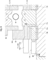
- Fig. 9 is an enlarged cross-sectional view showing the positional relationship between the respective members during the heating by energization.
- Fig. 10 is an enlarged cross-sectional view showing the positional relationship between the respective members during the forming.
- the die 13 or a member around the die may be magnetized (for example, see magnetic flux loops MP1 and MP2 of Fig. 13 to be described later).
- the forming device 10 is provided with the die movement suppressing part 110 that suppresses the movement of the die 13 by the electromagnetic force at least when the energization to the metal pipe material 14 is performed by the electrodes 17 and 18.
- the die movement suppressing part 110 is provided with a fixing part 111 that mechanically fixes the lower die 11 at least when the energization to the metal pipe material 14 is performed by the electrodes 17 and 18.
- the fixing part 111 is provided with a pin 112 that is inserted into a side surface 11e of the lower die 11 at least when the energization to the metal pipe material 14 is performed by the electrode 17 and a driving part 113 that drives the pin 112.
- the fixing part 111 is attached to a side surface 93h on the outer side of the first lower die holder 93.
- the position where the fixing part 111 is attached and the number of fixing parts are not particularly limited, and the fixing part 111 may be provided at a plurality of positions in the first lower die holder 93.
- the pin 112 is a rod-like member which is disposed vertically with respect to the side surface 11e of the lower die 11 and is driven to advance or retreat in the axial direction.
- a tip end part of the pin 112 is disposed at a position opposed to a recessed part 11b formed in the side surface 11e of the lower die 11 when the energization to the metal pipe material 14 is performed by the electrodes 17 and 18 (see Fig. 9 ).
- the pin 112 is inserted into the recessed part 11b through the first lower die holder 93.
- the driving part 113 applies a driving force in the axial direction to the pin 112.
- the driving part 113 is fixed to the side surface 93h of the first lower die holder 93.
- the driving system of the driving part 113 is not particularly limited, and a compressed air type actuator, a hydraulic actuator, or an electric actuator may be employed.
- the driving part 113 is a part for inserting the pin 112 into the recessed part 11b, and since a large driving force is not required, a compressed air type cylinder rod that is easy to handle may be used.
- Such a fixing part 111 drives the pin 112 by the driving part 113 and inserts the pin 112 into the recessed part 11b of the lower die 11 when the energization to the metal pipe material 14 is performed by the electrodes 17 and 18 (see Figs. 4(a), 4(b) , and 5 ).
- the fixing part 111 drives the pin 112 by the driving part 113 to remove the pin 112 from the recessed part 11b of the lower die 11 to thereby release the fixing.
- the upper die 12 is moved downward with the upward movement of the lower die 11, and the forming of the metal pipe material 14 is started.
- a support member 116 is disposed between the lower surface of the lower die 11 and the upper surface of the second lower die holder 94 by an actuator 114. Accordingly, the lower die 11 during the forming is supported by the support member 116.
- the die movement suppressing part 110 suppresses the movement of the die 13 by an electromagnetic force at least when the energization to the metal pipe material 14 is performed by the electrodes 17 and 18. That is, even in a case where a mechanism that heats the metal pipe material 14 by energization of the electrodes 17 and 18 is provided, it is possible to suppress the movement of the die 13 toward the metal pipe material 14 by an electromagnetic force. Accordingly, electrical leakage can be prevented from occurring due to the contact between the die 13 and the metal pipe material 14 during the heating by energization, and stability can be improved.
- the die movement suppressing part 110 is provided with the fixing part 111 that mechanically fixes the lower die 11 at least when the energization to the metal pipe material 14 is performed by the electrodes 17 and 18.
- the fixing part 111 mechanically fixes the lower die 11 that is easily moved by an electromagnetic force, the movement of the lower die 11 can be securely suppressed.
- the fixing part 111 is provided with the pin 112 that is inserted into the side surface 11e of the lower die 11 at least when the energization to the metal pipe material 14 is performed by the electrodes 17 and 18.
- the fixing part 111 can be simply configured, and interference with another mechanism can be avoided.
- the configuration of the fixing part 111 is not particularly limited as long as the fixing part can mechanically fix the lower die 11.
- a fixing part that fixes the lower die 11 from the lower side may be employed.
- a mechanism that is inserted into the lower die 11 from the lower side, and then bent in a horizontal direction may be provided. Otherwise, a mechanism that obliquely inserts a pin from the lower side of the lower die to the upper side may be employed.
- a configuration in which a pin is inserted in a longitudinal direction of the lower die 11 so as to avoid interference with a gas supply mechanism 40 may be employed.
- a die movement suppressing part 110 is provided with a die magnetization suppressing part 120 that suppresses the movement of a die 13 by an electromagnetic force by suppressing the magnetization of the die 13.
- the die magnetization suppressing part 120 is provided with a switching part 125 that switches the direction of a DC current that is supplied to electrodes 17 and 18.
- the switching part 125 shown in Fig. 11 is incorporated in the forming device 10 shown in Fig. 1 .
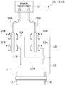
- the switching part 125 can switch connection points of the first electrodes 17 and the second electrodes 18 on the side of a positive electrode 126A and on the side of a negative electrode 126B of a power transformer 127. That is, the switching part 125 performs switching between a state in which the first electrode 17 is connected to the positive electrode 126A and the second electrode 18 is connected to the negative electrode 126B and a state in which the second electrode 18 is connected to the positive electrode 126A and the first electrode 17 is connected to the negative electrode 126B.
- the switching part 125 may perform switching during the heating by energization, for every heating by energization, or for every plural heating operations by energization.
- the switching by the switching part 125 may be performed automatically by a controller, or may be performed by an operation of an operator.
- the switching part 125 is provided with clamps 121A and 121B allowing the connection or release of the power transformer 127 with respect to the positive electrode 126A and clamps 122A and 122B allowing the connection or release of the power transformer 127 with respect to the negative electrode 126B.
- the respective clamps 121A, 121B, 122A, and 122B are opened or closed by an actuator. From a line L1 connected to the first electrode 17, a line L1A is branched and connected to the clamp 122A, and a line L1B is branched and connected to the clamp 121B. From a line L2 connected to the second electrode 18, a line L2A is branched and connected to the clamp 121A, and a line L2B is branched and connected to the clamp 122B.
- the switching part 125 connects the clamp 121B to the positive electrode 126A, and connects the clamp 122B to the negative electrode 126B in a case where the first electrode 17 is connected to the positive electrode 126A and the second electrode 18 is connected to the negative electrode 126B.
- the switching part 125 connects the clamp 121A to the positive electrode 126A, and connects the clamp 122A to the negative electrode 126B in a case where the second electrode 18 is connected to the positive electrode 126A and the first electrode 17 is connected to the negative electrode 126B.
- a switching part 130 shown in Figs. 12A and 12B may be employed.
- the switching part 130 performs connection switching between a bus bar 131 drawn from a first electrode 17 and a bus bar 132 drawn from a second electrode 18 and between a positive electrode 126A and a negative electrode 126B of a power transformer 127.
- the power transformer 127 is disposed on the side of the first electrode 17. Accordingly, the bus bar 132 drawn from the second electrode 18 extends toward the power transformer 127 while bypassing a die 13, a die holder, and the like.
- the bus bar 132 may be bent in a vertical direction according to the arrangement of obstacles.
- the bus bar 131 drawn from the first electrode 17 may have a U-shape as shown in Fig. 12C . By virtue of such a shape, a difference in length of the bus bar on the side of the switching part 130 can be absorbed by elastic deformation.
- the length can be absorbed by inward bending of an end part of the bus bar 131 as shown by the chain double-dashed line in Fig. 12C .
- the bus bar 131 drawn from the first electrode 17 is opposed to the positive electrode 126A of the power transformer 127, and the bus bar 132 drawn from the second electrode 18 is opposed to the negative electrode 126B of the power transformer 127.
- the bus bar 131 drawn from the first electrode 17 and the positive electrode 126A of the power transformer 127 are connected by a straight bus bar 133A
- the bus bar 132 drawn from the second electrode 18 and the negative electrode 126B of the power transformer 127 are connected by a straight bus bar 133B. Accordingly, the first electrode 17 is connected to the positive electrode 126A, and the second electrode 18 is connected to the negative electrode 126B.
- the current flow is switched from the above state, as shown in Fig.
- the bus bar 131 drawn from the first electrode 17 and the negative electrode 126B of the power transformer 127 are connected by a bus bar 134B extending in an oblique direction
- the bus bar 132 drawn from the second electrode 18 and the positive electrode 126A of the power transformer 127 are connected by a bus bar 134A extending in an oblique direction.
- the switching of the switching part 130 is performed by changing the bus bars by a manual operation of an operator.
- the die movement suppressing part 110 may be provided with the die magnetization suppressing part 120 that suppresses the movement of the die 13 by an electromagnetic force by suppressing the magnetization of the die 13.
- the electromagnetic force acting on the die 13 can be reduced when the energization to the metal pipe material 14 is performed by the electrodes 17 and 18. Accordingly, the movement of the die 13 by an electromagnetic force can be suppressed.
- the die magnetization suppressing part 120 is provided with the switching parts 125 and 130 that switch the direction of a DC current that is supplied to the electrodes 17 and 18.
- the magnetization of the die 13 can be cancelled by allowing a DC current in an opposite direction to flow to the electrodes 17 and 18. For example, in a case where the heating by energization is continued for a certain period of time in a state in which the first electrode 17 acts as a positive electrode and the second electrode 18 acts as a negative electrode, the die 13 is magnetized in a predetermined direction.
- the magnetization in the predetermined direction in the die 13 can be cancelled.
- a die movement suppressing part 110 is provided with a die magnetization suppressing part 120 that suppresses the movement of a die 13 by an electromagnetic force by suppressing the magnetization of the die 13.
- the die magnetization suppressing part 120 is provided with coils 140A and 140B surrounding the die 13.
- the coils 140A and 140B are provided to surround an upper die 12 and a lower die 11, respectively.
- the die magnetization suppressing part 120 is further provided with a magnetic flux loop forming part 150 including a protrusion 96b extending from an upper die holder 96 toward a lower die holder 93 at a position adjacent to the die 13.
- the coils 140A and 140B are provided to surround side surfaces of the upper die 12 and the lower die 11, respectively, and in this embodiment, the coils are disposed to be buried in the die holders 93 and 96, respectively.
- the coil 140A is disposed on the upper end side of the upper die 12, and the coil 140B is disposed on the lower end side of the lower die 11 so as not to be a disturbance during the forming.
- the coils 140A and 140B are provided in contact with the side surfaces of the upper die 12 and the lower die 11, respectively. Accordingly, magnetic fluxes of the coils 140A and 140B easily act on the upper die 12 and the lower die 11. However, the coils may be provided to be separated from the side surfaces of the upper die 12 and the lower die 11, respectively.
- the coils 140A and 140B may be provided on the outer peripheral sides of the die holders 93 and 96, respectively.
- An AC current or the like may be applied to the coils 140A and 140B while the amplitude is gradually reduced. Otherwise, not an AC current, a DC current may be applied to the coils 140A and 140B by positive/negative inversion.
- the operation timing of the coils 140A and 140B is not particularly limited. The operation may be performed during the heating by energization is performed, for every heating by energization, or for every plural heating operations by energization.
- the protrusion 96b constituting the magnetic flux loop forming part 150 protrudes downward from a step surface 96e and extends downward along the side surface of the upper die 12.
- the protrusion 96b extends downward more than an upper end surface 93e of a protrusion 93b of the first lower die holder 93, and extends downward more than an upper surface 11d of the lower die 11. That is, the protrusion 96b extends downward along the side surface of the lower die 11.
- the protrusion 96b is provided at a position adjacent to the upper die 12 and the lower die 11.
- the protrusion 96b is adjacent to the protrusion 93b of the first lower die holder 93 on a side opposite to the die 13.
- the die magnetization suppressing part 120 is provided with the coils 140A and 140B surrounding the die 13. Accordingly, the magnetization remaining in the die 13 can be cancelled with magnetic fluxes generated by the coils 140A and 140B.
- the coils 140A and 140B are provided to surround the upper die 12 and the lower die 11, respectively.
- the magnetization of the die 13 can be efficiently cancelled by providing the coils 140A and 140B in both of the upper die 12 and the lower die 11.
- a plurality of coils may be provided with respect to each of the upper die 12 and the lower die 11.
- the die magnetization suppressing part 120 is provided with the magnetic flux loop forming part 150 including the protrusion 96b extending from the first upper die holder 96 toward the first lower die holder 93 at a position adjacent to the die 13. Accordingly, the concentration of a magnetic flux loop MP in the lower die 11 and the upper die 12 can be suppressed, and thus promotion of the magnetization of the die 13 can be suppressed.
- the magnetic flux is directly directed from the upper die 12 to the lower die 11 and from the lower die 11 to the upper die 12 in a dominant manner as in a case of a magnetic flux loop MP2, and thus the magnetization of the die 13 easily proceeds due to the concentration of the magnetic flux in the die 13.
- the magnetic flux loop forming part 150 is formed, the magnetic flux is formed to be directed from the upper die 12 to the lower die 11 via the protrusion 96b and from the lower die 11 to the upper die 12 via the protrusion 96b as in a case of a magnetic flux loop MP1.
- the magnetic flux is formed to be directed from the upper die 12 to the lower die 11 via the protrusions 96b and 93b and from the lower die 11 to the upper die 12 via the protrusion 96b and 93b as in a case of a magnetic flux loop MP3. Accordingly, promotion of the magnetization of the die 13 can be suppressed as compared to a case where the magnetic flux is concentrated in the die 13.
- the magnetic flux loop forming part 150 may include a protrusion extending from the lower die 11 toward the upper die 12 along a side surface of the die 13.
- the protrusion 96b is adjacent to the first lower die holder 93 since it reaches the upper end surface 93e.
- the protrusion is also adjacent to the lower die 11 since it reaches the upper surface 11d.
- a magnetic flux loop can be effectively formed such that promotion of the magnetization of the die 13 can be suppressed.
- a preferable effect is also obtained in a case where the protrusion 96b reaches such a position that L3 is equal to or greater than L2.
- the relationship between L3 and L2 contributes to the magnetic flux loop MP3 of Fig. 13 .
- a more satisfactory effect is obtained in a case where L1 is equal to or greater than L2 than in a case where L3 is equal to or greater than L2.
- Both L1 and L3 may be equal to or greater than L2.
- a die movement suppressing part 110 is provided with a die magnetization suppressing part 120 that suppresses the movement of a die 13 by an electromagnetic force by suppressing the magnetization of the die 13.
- the die magnetization suppressing part 120 is provided with a magnetic flux loop forming part 150 including a protrusion 96b extending from an upper die holder 96 toward a lower die holder 93 at a position adjacent to the die 13.
- a protrusion 93g provided on the outer surface side of the first lower die holder 93 forms a leakage magnetic field suppressing part 160.
- the protrusion 93g constituting the leakage magnetic field suppressing part 160 extends upward from an edge part on the outer surface side of an upper end surface 93e of the first lower die holder 93.
- the protrusion 93g extends upward more than a step surface 96e of the first upper die holder 96. Accordingly, a gap between the step surface 96e and the upper end surface 93e is blocked by the protrusion 93g constituting the leakage magnetic field suppressing part 160.
- the die magnetization suppressing part 120 is provided with the magnetic flux loop forming part 150 including the protrusion 96b extending from the first upper die holder 96 toward the first lower die holder 93 at a position adjacent to the die 13. Accordingly, the concentration of a magnetic flux loop MP in the lower die 11 and the upper die 12 can be suppressed, and thus promotion of the magnetization of the die 13 can be suppressed.
- the protrusion 93g provided on the outer surface side of the first lower die holder 93 forms the leakage magnetic field suppressing part 160. Accordingly, it is possible to prevent a leakage magnetic field from affecting an external device with a simple configuration in which the first lower die holder 93 is provided with the protrusion 93g.
- the protrusion constituting the leakage magnetic field suppressing part 160 may be provided on the outer surface side of the first upper die holder 96. Otherwise, a plurality of protrusions provided alternately in the first upper die holder 96 and the first lower die holder 93 may constitute the leakage magnetic field suppressing part 160.
- the invention is not limited to the above-described embodiments.
- the above-described elements can be arbitrarily changed within such a range as not to change the concepts of the claims.
- the blow forming die 13 may be either a non-water cooling die or a water cooling die.
- a non-water cooling die requires a long period of time in a case where the die is cooled to near room temperature after the completion of the blow forming.
- the cooling is completed in a short period of time. Accordingly, a water cooling die is desirable from the viewpoint of an improvement in productivity.
- the upper die holding part 92 and the lower die holding part 91 are provided to hold the blow forming die 13.
- the holding parts 91 and 92 may be omitted in an embodiment in which the configurations itself of the holding parts 91 and 92 do not function as a die movement suppressing part.
- the forming device 10 may have at least one of the fixing part 111, the switching parts 125 and 130, the coil 140, and the magnetic flux loop forming part 150. Otherwise, the forming device 10 may have a configuration related to a combination of two or more of the fixing part 111, the switching parts 125 and 130, the coil 140, and the magnetic flux loop forming part 150, or may have all of them.
Landscapes
- Physics & Mathematics (AREA)
- Fluid Mechanics (AREA)
- Engineering & Computer Science (AREA)
- Mechanical Engineering (AREA)
- Shaping Metal By Deep-Drawing, Or The Like (AREA)
- Moulds For Moulding Plastics Or The Like (AREA)
Abstract
Description
- The present invention relates to a forming device.
- A forming device that forms a metal pipe by blow forming after closing a die has been known. For example, a forming device disclosed in
PTL 1 is provided with a die and a gas supply part that supplies a gas into a metal pipe material. In this forming device, a metal pipe material is disposed in the die, and in a state in which the die is closed, the metal pipe material is expanded by a gas supplied from the gas supply part to form the metal pipe material into a shape corresponding to a shape of the die. In this forming device, before the expansion of the metal pipe material, the metal pipe material is held by electrodes and heated by energization of the electrodes. - PTL 1: Japanese Unexamined Patent Application Publication No.
2012-000654 - Here, in the forming device, the die or a member around the die may be magnetized in a case where the metal pipe material is heated by energization of the electrodes. In such a case, while the metal pipe material is heated by energization, an electromagnetic force may act on the magnetized die such that the die is moved in a sliding direction that is a moving direction of the die. In a case where the die is moved by the electromagnetic force acting thereon and brought into contact with the metal pipe material during the heating by energization, electrical leakage may be caused via the die and the device may be damaged.
- The invention is contrived to solve the problem, and an object of an aspect of the invention is to provide a forming device in which stability can be improved.
- According to an aspect of the invention, there is provided a forming device that expands a metal pipe material to form a metal pipe includes a die that has an upper die and a lower die, at least one of which is movable, and that form the metal pipe, an electrode that energizes the metal pipe material to heat the metal pipe material, a gas supply part that supplies a gas into the heated metal pipe material to expand the metal pipe material, and a die movement suppressing part that suppresses the movement of the die by an electromagnetic force at least when the energization to the metal pipe material is performed by the electrode.
- According to the forming device, the die movement suppressing part suppresses the movement of the die by an electromagnetic force at least when the energization to the metal pipe material is performed by the electrode. That is, even in a case where a mechanism that heats the metal pipe material by energization of the electrode is provided, it is possible to suppress the movement of the die toward the metal pipe material by an electromagnetic force. Accordingly, stability can be improved.
- In the forming device, the die movement suppressing part may be provided with a fixing part that mechanically fixes the lower die at least when the energization to the metal pipe material is performed by the electrode. In a case where the fixing part mechanically fixes the lower die that is easily moved by an electromagnetic force, the movement of the lower die can be securely suppressed.
- In the forming device, the fixing part may be provided with a pin that is inserted into a side surface of the lower die at least when the energization to the metal pipe material is performed by the electrode. By employing a configuration in which the pin is inserted from the side surface side of the lower die, the fixing part can be simply configured, and interference with another mechanism can be avoided.
- In the forming device, the die movement suppressing part may be provided with a die magnetization suppressing part that suppresses the movement of the die by an electromagnetic force by suppressing the magnetization of the die. By suppressing the magnetization of the die by the die magnetization suppressing part, the electromagnetic force acting on the die can be reduced when the energization to the metal pipe material is performed by the electrode. Accordingly, the movement of the die by an electromagnetic force can be suppressed.
- In the forming device, the die magnetization suppressing part may be provided with a switching part that switches the direction of a DC current that is supplied to the electrode. The magnetization of the die can be cancelled by allowing a DC current in an opposite direction to flow to the electrode.
- In the forming device, the die magnetization suppressing part may be provided with a coil surrounding the die. The magnetization of the die can be cancelled with a magnetic flux generated by the coil.
- In the forming device, the coil may be provided to surround each of the upper die and the lower die. The magnetization of the die can be efficiently cancelled by providing the coil in both of the upper die and the lower die.
- In the forming device, the upper die may be supported by an upper die holder, the lower die may be supported by a lower die holder, and the die magnetization suppressing part may be provided with a magnetic flux loop forming part including a protrusion extending from one of the upper die holder and the lower die holder toward the other at a position adjacent to the die. Accordingly, the concentration of a magnetic flux loop in the lower die and the upper die can be suppressed, and thus promotion of the magnetization of the die can be suppressed.
- In the forming device, a protrusion provided on the outer surface side of at least one of the upper die holder and the lower die holder may form a leakage magnetic field suppressing part. Accordingly, it is possible to prevent a leakage magnetic field from affecting an external device with a simple configuration in which the die holder is provided with the protrusion.
- According to an aspect of the invention, the stability of the forming device can be improved.
-
-
Fig. 1 is a schematic diagram showing a configuration of a forming device according to a first embodiment of the invention. -
Fig. 2 is a transverse sectional view of a blow forming die and upper die and lower die holding parts, taken along the line II-II ofFig. 1 . -
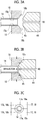
Figs. 3A to 3C are enlarged views of the vicinity of electrodes.Fig. 3A is a view showing a state in which a metal pipe material is held by the electrodes.Fig. 3B is a view showing a state in which a sealing member is brought into contact with the electrodes.Fig. 3C is a front view of the electrodes. -
Figs. 4(a) and 4(b) are diagrams showing a manufacturing step using the forming device.Fig. 4(a) is a diagram showing a state in which a metal pipe material is set in a die.Fig. 4 (b) is a diagram showing a state in which the metal pipe material is held by the electrodes. -
Fig. 5 is a diagram showing a manufacturing step following the steps inFigs. 4(a) and 4(b) . -
Fig. 6 is a diagram showing operations of the blow forming die and an upper die holder and a change in shape of the metal pipe material. -
Fig. 7 is a diagram followingFig. 6 . -
Fig. 8 is a diagram followingFig. 7 . -
Fig. 9 is an enlarged cross-sectional view showing the positional relationship between the respective members during the heating by energization. -
Fig. 10 is an enlarged cross-sectional view showing the positional relationship between the respective members during the forming. -
Fig. 11 is a schematic diagram showing a configuration of a switching part of a forming device according to a second embodiment. -
Figs. 12A to 12C are schematic diagrams showing a configuration of the switching part of the forming device according to the second embodiment. -
Fig. 13 is a schematic cross-sectional view of a forming device according to a third embodiment. -
Fig. 14 is a schematic cross-sectional view of a forming device according to a fourth embodiment. -
Fig. 15 is an enlarged view of the vicinity of an upper die and a lower die. - Hereinafter, preferable embodiments of a forming device according to an aspect of the invention will be described with reference to the drawings. In the drawings, the same or similar parts will be denoted by the same reference signs, and overlapping description will be omitted.
-
Fig. 1 is a schematic diagram of a configuration of a forming device, andFig. 2 is a transverse sectional view of a blow forming die and upper die and lower die holding parts, taken along the line II-II ofFig. 1 . As shown inFig. 1 , a forming device 10 that forms a metal pipe 100 (seeFig. 5 ) is provided with a blow forming die 13 composed of a pair of a lower die 11 and an upper die 12, a lower die holding part 91 for holding the lower die 11, an upper die holding part 92 for holding the upper die 12, a driving mechanism 80 that moves at least one of the lower die holding part 91 holding the lower die 11 and the upper die holding part 92 holding the upper die 12 (here, upper die holding part 92), a pipe holding mechanism 30 that holds a metal pipe material 14 shown by the virtual line between the lower die 11 and the upper die 12, a heating mechanism 50 that energizes the metal pipe material 14 held by the pipe holding mechanism 30 to heat the metal pipe material, a gas supply part 60 for supplying a high-pressure gas (gas) into the metal pipe material 14 held and heated between the lower die 11 and the upper die 12, a pair of gas supply mechanisms (gas supply part) 40 for supplying a gas into the metal pipe material 14 held by the pipe holding mechanism 30 from the gas supply part 60, and a water circulation mechanism 72 that forcibly cools the blow forming die 13 with water. The formingdevice 10 according to this embodiment is provided with a lowerdie driving mechanism 90 that drives thelower die 11 in a vertical direction. In addition, the formingdevice 10 is provided with acontroller 70 that controls driving of thedriving mechanism 80, driving of the lowerdie driving mechanism 90, driving of thepipe holding mechanism 30, driving of theheating mechanism 50, and gas supply of thegas supply part 60. - The
lower die 11 is fixed to alarge base 15 via the lowerdie holding part 91. Thelower die 11 is composed of a large steel block and is provided with a recessedpart 16 in an upper surface thereof (a parting surface from the upper die 12). As shown inFigs. 1 and2 , the lowerdie holding part 91 holding thelower die 11 is provided with a firstlower die holder 93 holding thelower die 11, a secondlower die holder 94 holding the firstlower die holder 93, and a lowerdie base plate 95 holding the secondlower die holder 94, that are laminated in order from the top. The lowerdie base plate 95 is fixed to thebase 15. As shown inFig. 1 , lengths of the firstlower die holder 93 and the secondlower die holder 94 in an axial direction (lengths in the horizontal direction inFig. 1 ) are almost the same as that of thelower die 11 in the axial direction. - An
electrode storage space 11a is provided near each of right and left ends (right and left ends inFig. 1 ) of thelower die 11, and afirst electrode 17 and asecond electrode 18 that are configured to advance or retreat in a vertical direction by an actuator (not shown) are provided in theelectrode storage spaces 11a. Recessedgrooves metal pipe material 14 are formed in upper surfaces of thefirst electrode 17 and thesecond electrode 18, respectively (seeFig. 3C ). Themetal pipe material 14 can be placed to be well fitted in the recessedgrooves second electrodes 17 and 18 (surfaces of the die in an outward direction), tapered recessedsurfaces grooves lower die 11 has a coolingwater passage 19 formed therein. On the lower surface side of thelower die 11, a lowerdie driving mechanism 90 extending in the vertical direction through the secondlower die holder 94 and the lowerdie base plate 95 is provided. The lowerdie driving mechanism 90 is provided with asupport part 101 supporting the lower surface of thelower die 11 and anaxial part 102 extending downward from thesupport part 101. The lower end side of theaxial part 102 is connected to a driving part (not shown). - The pair of first and
second electrodes lower die 11 constitute thepipe holding mechanism 30, and can elevatably support themetal pipe material 14 between theupper die 12 and thelower die 11. The formingdevice 10 is provided with a thermocouple (not shown) for measuring the temperature of themetal pipe material 14. For example, the thermocouple may be inserted from the side of thedie 13. The thermocouple is just an example of the temperature measuring unit, and a non-contact temperature sensor such as a radiation thermometer or an optical thermometer may be provided. A configuration without the temperature measuring unit may also be employed if the correlation between the energization time and the temperature can be obtained. - The
upper die 12 is a large steel block that is provided with a recessedpart 24 in a lower surface thereof (a parting surface from the lower die 11) and acooling water passage 25 built therein. As shown inFigs. 1 and2 , the upperdie holding part 92 holding theupper die 12 is provided with a firstupper die holder 96 holding theupper die 12, a secondupper die holder 97 holding the firstupper die holder 96, and an upperdie base plate 98 holding the secondupper die holder 97, that are laminated in order from the bottom. The upperdie base plate 98 is fixed to aslide 82. As shown inFig. 1 , lengths of the firstupper die holder 96 and the secondupper die holder 97 in an axial direction (lengths in the horizontal direction inFig. 1 ) are almost the same as that of theupper die 12 in the axial direction. Theslide 82 to which the upperdie holding part 92 is fixed is suspended by apressing cylinder 26, and is guided by aguide cylinder 27 so as not to laterally vibrate. - Similarly to the case of the
lower die 11, anelectrode storage space 12a is provided near each of right and left ends (right and left ends inFig. 1 ) of theupper die 12, and afirst electrode 17 and asecond electrode 18 that are configured to advance or retreat in the vertical direction by an actuator (not shown) are provided in theelectrode storage spaces 12a. Recessedgrooves metal pipe material 14 are formed in lower surfaces of the first andsecond electrodes Fig. 3C ), and themetal pipe material 14 can be well fitted in the recessedgrooves second electrodes 17 and 18 (surfaces of the die in an outward direction), tapered recessedsurfaces grooves second electrodes upper die 12 also constitute thepipe holding mechanism 30 and themetal pipe material 14 is sandwiched between the upper and lower pairs of first andsecond electrodes metal pipe material 14 can be surrounded such that the outer periphery thereof firmly adheres well over the whole periphery. The fixing parts of the respective actuators moving thefirst electrode 17 and thesecond electrode 18 corresponding to a moving part up and down are held and fixed to the lowerdie holding part 91 and the upperdie holding part 92, respectively. - The
driving mechanism 80 is provided with aslide 82 that moves theupper die 12 and the upperdie holding part 92 so as to combine theupper die 12 and thelower die 11 together, a driving part 81 that generates a driving force for moving theslide 82, and a servo motor 83 that controls a fluid amount with respect to the driving part 81. The driving part 81 is composed of a fluid supply part that supplies a fluid (an operating oil in a case where a hydraulic cylinder is employed as the pressing cylinder 26) for driving thepressing cylinder 26 to thepressing cylinder 26. - The
controller 70 can control the movement of theslide 82 by controlling the amount of the fluid to be supplied to thepressing cylinder 26 by controlling the servo motor 83 of the driving part 81. The driving part 81 is not limited to a part that applies a driving force to theslide 82 via thepressing cylinder 26 as described above. For example, the driving part may be mechanically connected to theslide 82 to directly or indirectly apply a driving force generated by the servo motor 83 to theslide 82. For example, a driving mechanism having an eccentric shaft, a driving source (for example, a servo motor and a reducer) that applies a rotating force for rotating the eccentric shaft, and a converter (for example, a connecting rod or an eccentric sleeve) that converts the rotational movement of the eccentric shaft into the linear movement to move the slide may be employed. In this embodiment, the driving part 81 may not have the servo motor 83. - As shown in
Fig. 2 , an upper end surface of thelower die 11 and a lower end surface of theupper die 12 are uneven. Specifically, the recessedpart 16 with a rectangular cross-sectional shape is formed at the center of the upper end surface of thelower die 11, and the recessedpart 24 with a rectangular cross-sectional shape is formed at the center of the lower end surface of theupper die 12 to be opposed to the recessedpart 16 of thelower die 11. - The first
lower die holder 93 that constitutes the lowerdie holding part 91 and holds thelower die 11 is provided with a recessedpart 93a with a rectangular cross-sectional shape at a center of anupper end surface 93e of the rectangular parallelepiped. Thelower die 11 is held such that the substantially lower half thereof is fitted into agap 93c provided at the center of abottom surface 93d of the recessedpart 93a and dividing the firstlower die holder 93. Spaces S1 and S2 are respectively provided betweenprotrusions 93b at both sides that form the recessedpart 93a of the firstlower die holder 93 and side surfaces of the substantially upper half of thelower die 11 that protrude higher than thebottom surface 93d of the firstlower die holder 93, andprotrusions 96b of the firstupper die holder 96 to be described later proceed into the spaces S1 and S2 in a case where theblow forming die 13 is closed. - The first
upper die holder 96 that constitutes the upperdie holding part 92 and holds theupper die 12 is formed into a stepped block shape, in which the rectangular parallelepiped becomes smaller downward in a stepwise manner, by forming two steps toward the lower side from the upper side at both sides of the rectangular parallelepiped. A recessedpart 96a with a rectangular cross-sectional shape is formed at a center of alower end surface 96d of the firstupper die holder 96, and theupper die 12 is held to be housed in the recessedpart 96a. Accordingly, inner surfaces of theprotrusions 96b at both sides that form the recessedpart 96a of the firstupper die holder 96 are brought into contact with the side surfaces of theupper die 12. In addition, theprotrusions 96b protrude downward from the lower end surface of theupper die 12 by a predetermined length, and respectively proceed into the spaces S1 and S2 of the firstlower die holder 93 in a case where theblow forming die 13 is closed. In addition, in a case where theblow forming die 13 is closed, the lower end surface (tip end surface) 96d of theprotrusion 96b of the firstupper die holder 96 is brought into contact with thebottom surface 93d of the recessedpart 93a of the firstlower die holder 93, andstep surfaces 96e that form theprotrusions 96b at both sides of theprotrusions 96b of the firstupper die holder 96 and are positioned above theprotrusions 96b are brought into contact with the upper end surfaces 93e of theprotrusions 93b of the firstlower die holder 93. - As shown in
Fig. 1 , theheating mechanism 50 has the first andsecond electrodes power supply 51,conductive wires 52 that extend from thepower supply 51 and are connected to the first andsecond electrodes switch 53 that is provided in theconductive wire 52. Thecontroller 70 controls theheating mechanism 50, and thus themetal pipe material 14 can be heated to a quenching temperature (equal to or higher than an AC3 transformation temperature). - Each of the pair of
gas supply mechanisms 40 has acylinder unit 42, acylinder rod 43 that advances or retreats in accordance with the operation of thecylinder unit 42, and a sealingmember 44 that is connected to a tip end of thecylinder rod 43 on the side of thepipe holding mechanism 30. Thecylinder unit 42 is placed and fixed on thebase 15 via ablock 41. A taperedsurface 45 is formed at a tip end of the sealingmember 44 so as to be tapered. The tapered surfaces are formed into such a shape as to be well fitted in and brought into contact with the tapered recessedsurfaces second electrodes 17 and 18 (seeFigs. 3A to 3C ). The sealingmember 44 is provided with agas passage 46 that extends from thecylinder unit 42 toward the tip end, specifically, through which a high-pressure gas supplied from thegas supply part 60 flows as shown inFigs. 3A and 3B . - As shown in
Fig. 1 , thegas supply part 60 includes a high-pressure gas supply 61, anaccumulator 62 that stores a gas supplied by the high-pressure gas supply 61, afirst tube 63 that extends from theaccumulator 62 to thecylinder unit 42 of thegas supply mechanism 40, apressure control valve 64 and a switchingvalve 65 that are provided in thefirst tube 63, asecond tube 67 that extends from theaccumulator 62 to thegas passage 46 formed in the sealingmember 44, and apressure control valve 68 and acheck valve 69 that are provided in thesecond tube 67. Thepressure control valve 64 functions to supply, to thecylinder unit 42, a gas having an operation pressure adapted for the pressing force of the sealingmember 44 with respect to themetal pipe material 14. Thecheck valve 69 functions to prevent the high-pressure gas from flowing backward in thesecond tube 67. - The
controller 70 controls thepressure control valve 68 of thegas supply part 60, and thus a gas having a desired operation pressure can be supplied into themetal pipe material 14. In addition, thecontroller 70 acquires temperature information from the thermocouple (not shown), and controls thepressing cylinder 26 and theswitch 53. - The
water circulation mechanism 72 includes awater tank 73 that stores water, awater pump 74 that draws up and pressurizes the water stored in thewater tank 73 to send the water to the coolingwater passage 19 of thelower die 11 and the coolingwater passage 25 of theupper die 12, and apipe 75. Although omitted, a cooling tower that lowers the water temperature or a filter that purifies the water may be provided in thepipe 75. - Next, a method of forming a metal pipe using the forming
device 10 will be described.Figs. 4 (a) and 4 (b) show steps from a pipe injection step for injecting themetal pipe material 14 as a material to an energization and heating step for heating themetal pipe material 14 by energization. More specifically,Fig. 4(a) is a diagram showing a state in which the metal pipe material is set in the die.Fig. 4(b) is a diagram showing a state in which the metal pipe material is held by the electrodes.Fig. 5 is a diagram showing a manufacturing step following the steps inFigs. 4(a) and 4(b) . - First, a
metal pipe material 14 that is a quenchable steel type is prepared. As shown inFig. 4(a) , themetal pipe material 14 is placed (injected) on the first andsecond electrodes lower die 11 using, for example, a robot arm or the like. Since the first andsecond electrodes grooves metal pipe material 14 is positioned by the recessedgrooves Fig. 1 ) controls thepipe holding mechanism 30 to hold themetal pipe material 14 by thepipe holding mechanism 30. Specifically, as inFig. 4(b) , an actuator (not shown) that allows the first andsecond electrodes second electrodes metal pipe material 14 are sandwiched between the first andsecond electrodes grooves second electrodes metal pipe material 14 is sandwiched so as to firmly adhere over the whole periphery thereof. - Next, as shown in
Fig. 1 , thecontroller 70 controls theheating mechanism 50 to heat themetal pipe material 14. Specifically, thecontroller 70 turns on theswitch 53 of theheating mechanism 50. In that case, electric power is supplied from thepower supply 51 to themetal pipe material 14, and themetal pipe material 14 produces heat (Joule heat) due to the resistance present in themetal pipe material 14. In this case, the measurement value of the thermocouple is always monitored, and based on the results thereof, the energization is controlled and thecylinder unit 42 of thegas supply mechanism 40 is operated. Accordingly, both ends of themetal pipe material 14 are sealed by the sealing member 44 (see alsoFigs. 3A to 3C ) . -
Fig. 6 is a diagram showing operations of the blow forming die and the first upper die holder and a change in shape of the metal pipe material.Fig. 7 is a diagram followingFig. 6 .Fig. 8 is a diagram followingFig. 7 . - As shown in
Fig. 6 , theblow forming die 13 is closed with respect to themetal pipe material 14 after heating. In this case, theprotrusions 96b of the firstupper die holder 96 proceed into the spaces S1 and S2 of the firstlower die holder 93, and between the recessedpart 16 of thelower die 11 and the recessedpart 24 of theupper die 12, a main cavity part MC with a substantially rectangular cross-sectional shape is formed that is a gap for forming a pipe part (main body part) 100a. With this, sub-cavity parts SC1 and SC2 that communicate with the main cavity part MC and are gaps for formingflange parts lower die 11 and the lower end surface of theupper die 12. - Here, the sub-cavity parts SC1 and SC2 between the upper end surface of the
lower die 11 and the lower end surface of theupper die 12 extend to be opened to the outside of the die. The sub-cavity parts SC1 and SC2 are blocked from the outside byinner surfaces 96f of theprotrusions 96b of the firstupper die holder 96. Theprotrusions 96b of the firstupper die holder 96, blocking the sub-cavity parts SC1 and SC2 from the outside of the die, are operated such that foreign matter such as fragments generated when, for example, the metal pipe bursts in the die is prevented from advancing out of the die through the sub-cavity parts SC1 and SC2 and from being discharged. Accordingly, the firstupper die holder 96 having theprotrusions 96b also functions as a shielding member. - In this state, that is, in a state before the blow forming die is completely closed, the
metal pipe material 14 is fitted in the main cavity part MC, and in a state in which the metal pipe material is in contact with the bottom surface of the recessedpart 16 of thelower die 11 and the bottom surface of the recessedpart 24 of theupper die 12, a high-pressure gas is supplied into themetal pipe material 14 by thegas supply part 60 to start blow forming. - Here, since the
metal pipe material 14 is softened by being heated at a high temperature (about 950°C), the gas supplied into themetal pipe material 14 is thermally expanded. Therefore, for example, with the use of compressed air as a gas to be supplied, themetal pipe material 14 at 950°C can be easily expanded by thermally expanded compressed air. - In parallel with this, the
blow forming die 13 is further closed, and as shown inFig. 7 , the main cavity part MC and the sub-cavity parts SC1 and SC2 are further narrowed between thelower die 11 and theupper die 12. - Accordingly, the
metal pipe material 14 is expanded in the main cavity part MC so as to follow the recessedparts metal pipe material 14 are expanded so as to enter into the sub-cavity parts SC1 and SC2, respectively. - As shown in
Fig. 8 , theblow forming die 13 is further closed, and thus thelower end surface 96d of theprotrusion 96b of the firstupper die holder 96 is brought into contact with thebottom surface 93d of the recessedpart 93a of the firstlower die holder 93, thestep surface 96e of the firstupper die holder 96 is brought into contact with theupper end surface 93e of theprotrusion 93b of the firstlower die holder 93, and the inner surface of theprotrusion 93b of the firstlower die holder 93 and the outer surface of theprotrusion 96b of the firstupper die holder 96 are brought into contact with each other. In a state in which the firstlower die holder 93 and the firstupper die holder 96 are firmly adhered to each other, the closing of theblow forming die 13 is completed. - In this case, the main cavity part MC and the sub-cavity parts SC1 and SC2 are further narrowed than in the state shown in
Fig. 7 , and in this state, the sub-cavity parts SC1 and SC2 are blocked from the outside by theinner surfaces 96f of theprotrusions 96b of the firstupper die holder 96 as described above. - Accordingly, the
metal pipe material 14 softened by heating and supplied with the high-pressure gas is formed as thepipe part 100a with a rectangular cross-sectional shape following the rectangular cross-sectional shape of the main cavity part MC in the main cavity part MC, and formed as theflange parts metal pipe material 14 is folded in the sub-cavity parts SC1 and SC2. - In this blow forming, quenching is performed in such a way that the outer peripheral surface of the
metal pipe material 14 expanded by being subjected to the blow forming is brought into contact with the recessedpart 16 of thelower die 11 so as to be rapidly cooled, and simultaneously, brought into contact with the recessedpart 24 of theupper die 12 so as to be rapidly cooled (since theupper die 12 and thelower die 11 have a large heat capacity and are managed at a low temperature, the heat of the pipe surface is taken to the dies at once in a case where themetal pipe material 14 is brought into contact with the dies.). Such a cooling method is referred to as die contact cooling or die cooling. Immediately after the rapid cooling, the austenite is transformed to martensite (hereinafter, transformation of austenite to martensite will be referred to as martensite transformation). Since the cooling rate is reduced in the second half of the cooling, the martensite is transformed to another structure (troostite, sorbate, or the like) owing to recuperation. Therefore, there is no need to perform a separate tempering treatment. In this embodiment, in place of or in addition to the die cooling, a cooling medium may be supplied to themetal pipe 100 to perform cooling. For example, themetal pipe material 14 may be brought into contact with the die (upper die 12 and lower die 11) to be cooled until the temperature is lowered to a temperature at which the martensite transformation starts, and then, the die may be opened and a cooling medium (gas for cooling) may be allowed to flow to themetal pipe material 14 to cause the martensite transformation. In this description, the description is made using a case where themetal pipe material 14 is steel as an example. - By the above-described forming method, the
metal pipe 100 having thepipe part 100a and theflange parts Fig. 5 . In this embodiment, since the main cavity part MC is configured to have a rectangular cross-sectional shape, themetal pipe material 14 is subjected to the blow forming in accordance with the shape, and thus thepipe part 100a is formed into a rectangular cylindrical shape. The shape of the main cavity part MC is not particularly limited. In accordance with a desired shape, any shape may be employed such as a circular cross-sectional shape, an elliptical cross-sectional shape, or a polygonal cross-sectional shape. - Next, a configuration of a die movement suppressing part 110 of the forming
device 10 according to this embodiment will be described with reference toFigs. 9 and10 .Fig. 9 is an enlarged cross-sectional view showing the positional relationship between the respective members during the heating by energization.Fig. 10 is an enlarged cross-sectional view showing the positional relationship between the respective members during the forming. In the formingdevice 10, in a case where themetal pipe material 14 is heated by energization of theelectrodes Fig. 13 to be described later). In such a case, while themetal pipe material 14 is heated by energization, an electromagnetic force may act on the magnetized die 13 such that thedie 13 is moved in a sliding direction that is a moving direction of thedie 13. In a case where thedie 13 is moved by the electromagnetic force acting thereon and brought into contact with themetal pipe material 14 during the heating by energization, electrical leakage may be caused via thedie 13 and the device may be damaged. Accordingly, the formingdevice 10 according to this embodiment is provided with the die movement suppressing part 110 that suppresses the movement of the die 13 by the electromagnetic force at least when the energization to themetal pipe material 14 is performed by theelectrodes - As shown in
Figs. 9 and10 , the die movement suppressing part 110 is provided with a fixing part 111 that mechanically fixes thelower die 11 at least when the energization to themetal pipe material 14 is performed by theelectrodes pin 112 that is inserted into aside surface 11e of thelower die 11 at least when the energization to themetal pipe material 14 is performed by theelectrode 17 and a drivingpart 113 that drives thepin 112. The fixing part 111 is attached to aside surface 93h on the outer side of the firstlower die holder 93. The position where the fixing part 111 is attached and the number of fixing parts are not particularly limited, and the fixing part 111 may be provided at a plurality of positions in the firstlower die holder 93. - The
pin 112 is a rod-like member which is disposed vertically with respect to theside surface 11e of thelower die 11 and is driven to advance or retreat in the axial direction. A tip end part of thepin 112 is disposed at a position opposed to a recessedpart 11b formed in theside surface 11e of thelower die 11 when the energization to themetal pipe material 14 is performed by theelectrodes 17 and 18 (seeFig. 9 ). Thepin 112 is inserted into the recessedpart 11b through the firstlower die holder 93. - The driving
part 113 applies a driving force in the axial direction to thepin 112. The drivingpart 113 is fixed to theside surface 93h of the firstlower die holder 93. The driving system of the drivingpart 113 is not particularly limited, and a compressed air type actuator, a hydraulic actuator, or an electric actuator may be employed. The drivingpart 113 is a part for inserting thepin 112 into the recessedpart 11b, and since a large driving force is not required, a compressed air type cylinder rod that is easy to handle may be used. - Such a fixing part 111 drives the
pin 112 by the drivingpart 113 and inserts thepin 112 into the recessedpart 11b of thelower die 11 when the energization to themetal pipe material 14 is performed by theelectrodes 17 and 18 (seeFigs. 4(a), 4(b) , and5 ). In a case where the heating by energization is completed, the fixing part 111 drives thepin 112 by the drivingpart 113 to remove thepin 112 from the recessedpart 11b of thelower die 11 to thereby release the fixing. Then, theupper die 12 is moved downward with the upward movement of thelower die 11, and the forming of themetal pipe material 14 is started. After thelower die 11 is moved upward, asupport member 116 is disposed between the lower surface of thelower die 11 and the upper surface of the secondlower die holder 94 by anactuator 114. Accordingly, thelower die 11 during the forming is supported by thesupport member 116. - As described above, according to the forming
device 10 according to this embodiment, the die movement suppressing part 110 suppresses the movement of the die 13 by an electromagnetic force at least when the energization to themetal pipe material 14 is performed by theelectrodes metal pipe material 14 by energization of theelectrodes metal pipe material 14 by an electromagnetic force. Accordingly, electrical leakage can be prevented from occurring due to the contact between the die 13 and themetal pipe material 14 during the heating by energization, and stability can be improved. - In the forming
device 10 according to this embodiment, the die movement suppressing part 110 is provided with the fixing part 111 that mechanically fixes thelower die 11 at least when the energization to themetal pipe material 14 is performed by theelectrodes lower die 11 that is easily moved by an electromagnetic force, the movement of thelower die 11 can be securely suppressed. - In the forming
device 10 according to this embodiment, the fixing part 111 is provided with thepin 112 that is inserted into theside surface 11e of thelower die 11 at least when the energization to themetal pipe material 14 is performed by theelectrodes pin 112 is inserted from theside surface 11e of thelower die 11, the fixing part 111 can be simply configured, and interference with another mechanism can be avoided. - The configuration of the fixing part 111 is not particularly limited as long as the fixing part can mechanically fix the
lower die 11. For example, a fixing part that fixes thelower die 11 from the lower side may be employed. For example, a mechanism that is inserted into thelower die 11 from the lower side, and then bent in a horizontal direction may be provided. Otherwise, a mechanism that obliquely inserts a pin from the lower side of the lower die to the upper side may be employed. In addition, a configuration in which a pin is inserted in a longitudinal direction of thelower die 11 so as to avoid interference with agas supply mechanism 40 may be employed. - In a forming
device 10 according to a second embodiment of the invention, a die movement suppressing part 110 is provided with a die magnetization suppressing part 120 that suppresses the movement of a die 13 by an electromagnetic force by suppressing the magnetization of thedie 13. In addition, as shown inFig. 11 , in the formingdevice 10 according to the second embodiment, the die magnetization suppressing part 120 is provided with a switching part 125 that switches the direction of a DC current that is supplied toelectrodes Fig. 11 is incorporated in the formingdevice 10 shown inFig. 1 . - As shown in
Fig. 11 , the switching part 125 can switch connection points of thefirst electrodes 17 and thesecond electrodes 18 on the side of apositive electrode 126A and on the side of anegative electrode 126B of apower transformer 127. That is, the switching part 125 performs switching between a state in which thefirst electrode 17 is connected to thepositive electrode 126A and thesecond electrode 18 is connected to thenegative electrode 126B and a state in which thesecond electrode 18 is connected to thepositive electrode 126A and thefirst electrode 17 is connected to thenegative electrode 126B. The switching part 125 may perform switching during the heating by energization, for every heating by energization, or for every plural heating operations by energization. The switching by the switching part 125 may be performed automatically by a controller, or may be performed by an operation of an operator. - Specifically, the switching part 125 is provided with
clamps power transformer 127 with respect to thepositive electrode 126A and clamps 122A and 122B allowing the connection or release of thepower transformer 127 with respect to thenegative electrode 126B. The respective clamps 121A, 121B, 122A, and 122B are opened or closed by an actuator. From a line L1 connected to thefirst electrode 17, a line L1A is branched and connected to theclamp 122A, and a line L1B is branched and connected to theclamp 121B. From a line L2 connected to thesecond electrode 18, a line L2A is branched and connected to theclamp 121A, and a line L2B is branched and connected to theclamp 122B. - The switching part 125 connects the
clamp 121B to thepositive electrode 126A, and connects theclamp 122B to thenegative electrode 126B in a case where thefirst electrode 17 is connected to thepositive electrode 126A and thesecond electrode 18 is connected to thenegative electrode 126B. The switching part 125 connects theclamp 121A to thepositive electrode 126A, and connects theclamp 122A to thenegative electrode 126B in a case where thesecond electrode 18 is connected to thepositive electrode 126A and thefirst electrode 17 is connected to thenegative electrode 126B. - Otherwise, a switching part 130 shown in
Figs. 12A and 12B may be employed. The switching part 130 performs connection switching between abus bar 131 drawn from afirst electrode 17 and abus bar 132 drawn from asecond electrode 18 and between apositive electrode 126A and anegative electrode 126B of apower transformer 127. - The
power transformer 127 is disposed on the side of thefirst electrode 17. Accordingly, thebus bar 132 drawn from thesecond electrode 18 extends toward thepower transformer 127 while bypassing adie 13, a die holder, and the like. Thebus bar 132 may be bent in a vertical direction according to the arrangement of obstacles. Thebus bar 131 drawn from thefirst electrode 17 may have a U-shape as shown inFig. 12C . By virtue of such a shape, a difference in length of the bus bar on the side of the switching part 130 can be absorbed by elastic deformation. For example, in a case where the bus bar on the side of the switching part 130 is long, the length can be absorbed by inward bending of an end part of thebus bar 131 as shown by the chain double-dashed line inFig. 12C . Thebus bar 131 drawn from thefirst electrode 17 is opposed to thepositive electrode 126A of thepower transformer 127, and thebus bar 132 drawn from thesecond electrode 18 is opposed to thenegative electrode 126B of thepower transformer 127. - As shown in
Fig. 12A , in the switching part 130, thebus bar 131 drawn from thefirst electrode 17 and thepositive electrode 126A of thepower transformer 127 are connected by astraight bus bar 133A, and thebus bar 132 drawn from thesecond electrode 18 and thenegative electrode 126B of thepower transformer 127 are connected by astraight bus bar 133B. Accordingly, thefirst electrode 17 is connected to thepositive electrode 126A, and thesecond electrode 18 is connected to thenegative electrode 126B. In a case where the current flow is switched from the above state, as shown inFig. 12B , in the switching part 130, thebus bar 131 drawn from thefirst electrode 17 and thenegative electrode 126B of thepower transformer 127 are connected by abus bar 134B extending in an oblique direction, and thebus bar 132 drawn from thesecond electrode 18 and thepositive electrode 126A of thepower transformer 127 are connected by abus bar 134A extending in an oblique direction. The switching of the switching part 130 is performed by changing the bus bars by a manual operation of an operator. - As described above, in the forming
device 10 according to the second embodiment, the die movement suppressing part 110 may be provided with the die magnetization suppressing part 120 that suppresses the movement of the die 13 by an electromagnetic force by suppressing the magnetization of thedie 13. In this manner, by suppressing the magnetization of the die 13 by the die magnetization suppressing part 120, the electromagnetic force acting on the die 13 can be reduced when the energization to themetal pipe material 14 is performed by theelectrodes - In the forming
device 10 according to the second embodiment, the die magnetization suppressing part 120 is provided with the switching parts 125 and 130 that switch the direction of a DC current that is supplied to theelectrodes electrodes first electrode 17 acts as a positive electrode and thesecond electrode 18 acts as a negative electrode, thedie 13 is magnetized in a predetermined direction. However, in a case where the heating by energization is performed with a DC current flow reversed with thefirst electrode 17 acting as a negative electrode and thesecond electrode 18 acting as a positive electrode, the magnetization in the predetermined direction in the die 13 can be cancelled. - In a forming
device 10 according to a third embodiment of the invention, a die movement suppressing part 110 is provided with a die magnetization suppressing part 120 that suppresses the movement of a die 13 by an electromagnetic force by suppressing the magnetization of thedie 13. In addition, as shown inFig. 13 , in the formingdevice 10 according to the third embodiment, the die magnetization suppressing part 120 is provided with coils 140A and 140B surrounding thedie 13. The coils 140A and 140B are provided to surround anupper die 12 and alower die 11, respectively. The die magnetization suppressing part 120 is further provided with a magnetic flux loop forming part 150 including aprotrusion 96b extending from anupper die holder 96 toward alower die holder 93 at a position adjacent to thedie 13. - The coils 140A and 140B are provided to surround side surfaces of the
upper die 12 and thelower die 11, respectively, and in this embodiment, the coils are disposed to be buried in thedie holders upper die 12, and the coil 140B is disposed on the lower end side of thelower die 11 so as not to be a disturbance during the forming. The coils 140A and 140B are provided in contact with the side surfaces of theupper die 12 and thelower die 11, respectively. Accordingly, magnetic fluxes of the coils 140A and 140B easily act on theupper die 12 and thelower die 11. However, the coils may be provided to be separated from the side surfaces of theupper die 12 and thelower die 11, respectively. The coils 140A and 140B may be provided on the outer peripheral sides of thedie holders - In a state in which the heating by energization is performed as shown in
Fig. 13 , theprotrusion 96b constituting the magnetic flux loop forming part 150 protrudes downward from astep surface 96e and extends downward along the side surface of theupper die 12. In addition, theprotrusion 96b extends downward more than anupper end surface 93e of aprotrusion 93b of the firstlower die holder 93, and extends downward more than anupper surface 11d of thelower die 11. That is, theprotrusion 96b extends downward along the side surface of thelower die 11. In this manner, theprotrusion 96b is provided at a position adjacent to theupper die 12 and thelower die 11. In addition, theprotrusion 96b is adjacent to theprotrusion 93b of the firstlower die holder 93 on a side opposite to thedie 13. - As described above, in the forming
device 10 according to the third embodiment, the die magnetization suppressing part 120 is provided with the coils 140A and 140B surrounding thedie 13. Accordingly, the magnetization remaining in the die 13 can be cancelled with magnetic fluxes generated by the coils 140A and 140B. - In the forming
device 10 according to the third embodiment, the coils 140A and 140B are provided to surround theupper die 12 and thelower die 11, respectively. The magnetization of the die 13 can be efficiently cancelled by providing the coils 140A and 140B in both of theupper die 12 and thelower die 11. However, there is no need to provide both of the coil 140A associated with theupper die 12 and the coil 140B associated with thelower die 11, and any one of them may be provided. A plurality of coils may be provided with respect to each of theupper die 12 and thelower die 11. - In the forming
device 10 according to the third embodiment, the die magnetization suppressing part 120 is provided with the magnetic flux loop forming part 150 including theprotrusion 96b extending from the firstupper die holder 96 toward the firstlower die holder 93 at a position adjacent to thedie 13. Accordingly, the concentration of a magnetic flux loop MP in thelower die 11 and theupper die 12 can be suppressed, and thus promotion of the magnetization of the die 13 can be suppressed. - For example, in a case where the
protrusion 96b constituting the magnetic flux loop forming part 150 is not provided, the magnetic flux is directly directed from theupper die 12 to thelower die 11 and from thelower die 11 to theupper die 12 in a dominant manner as in a case of a magnetic flux loop MP2, and thus the magnetization of the die 13 easily proceeds due to the concentration of the magnetic flux in thedie 13. In a case where the magnetic flux loop forming part 150 is formed, the magnetic flux is formed to be directed from theupper die 12 to thelower die 11 via theprotrusion 96b and from thelower die 11 to theupper die 12 via theprotrusion 96b as in a case of a magnetic flux loop MP1. In addition, the magnetic flux is formed to be directed from theupper die 12 to thelower die 11 via theprotrusions lower die 11 to theupper die 12 via theprotrusion die 13. - The magnetic flux loop forming part 150 may include a protrusion extending from the
lower die 11 toward theupper die 12 along a side surface of thedie 13. In the embodiment shown inFig. 13 , theprotrusion 96b is adjacent to the firstlower die holder 93 since it reaches theupper end surface 93e. The protrusion is also adjacent to thelower die 11 since it reaches theupper surface 11d. However, in the positional relationship shown inFig. 15 , in a case where theprotrusion 96b reaches such a position that L1 is equal to or greater than L2, a magnetic flux loop can be effectively formed such that promotion of the magnetization of the die 13 can be suppressed. A preferable effect is also obtained in a case where theprotrusion 96b reaches such a position that L3 is equal to or greater than L2. The relationship between L3 and L2 contributes to the magnetic flux loop MP3 ofFig. 13 . A more satisfactory effect is obtained in a case where L1 is equal to or greater than L2 than in a case where L3 is equal to or greater than L2. Both L1 and L3 may be equal to or greater than L2. - In a forming
device 10 according to a fourth embodiment of the invention, a die movement suppressing part 110 is provided with a die magnetization suppressing part 120 that suppresses the movement of a die 13 by an electromagnetic force by suppressing the magnetization of thedie 13. In addition, as shown inFig. 14 , the die magnetization suppressing part 120 is provided with a magnetic flux loop forming part 150 including aprotrusion 96b extending from anupper die holder 96 toward alower die holder 93 at a position adjacent to thedie 13. In addition, in the formingdevice 10 according to the fourth embodiment, aprotrusion 93g provided on the outer surface side of the firstlower die holder 93 forms a leakage magneticfield suppressing part 160. - The
protrusion 93g constituting the leakage magneticfield suppressing part 160 extends upward from an edge part on the outer surface side of anupper end surface 93e of the firstlower die holder 93. Theprotrusion 93g extends upward more than astep surface 96e of the firstupper die holder 96. Accordingly, a gap between thestep surface 96e and theupper end surface 93e is blocked by theprotrusion 93g constituting the leakage magneticfield suppressing part 160. - As described above, in the forming
device 10 according to the fourth embodiment, the die magnetization suppressing part 120 is provided with the magnetic flux loop forming part 150 including theprotrusion 96b extending from the firstupper die holder 96 toward the firstlower die holder 93 at a position adjacent to thedie 13. Accordingly, the concentration of a magnetic flux loop MP in thelower die 11 and theupper die 12 can be suppressed, and thus promotion of the magnetization of the die 13 can be suppressed. - In the forming
device 10 according to the fourth embodiment, theprotrusion 93g provided on the outer surface side of the firstlower die holder 93 forms the leakage magneticfield suppressing part 160. Accordingly, it is possible to prevent a leakage magnetic field from affecting an external device with a simple configuration in which the firstlower die holder 93 is provided with theprotrusion 93g. The protrusion constituting the leakage magneticfield suppressing part 160 may be provided on the outer surface side of the firstupper die holder 96. Otherwise, a plurality of protrusions provided alternately in the firstupper die holder 96 and the firstlower die holder 93 may constitute the leakage magneticfield suppressing part 160. - The invention is not limited to the above-described embodiments. In a forming device according to an aspect of the invention, the above-described elements can be arbitrarily changed within such a range as not to change the concepts of the claims.
- The
blow forming die 13 may be either a non-water cooling die or a water cooling die. However, a non-water cooling die requires a long period of time in a case where the die is cooled to near room temperature after the completion of the blow forming. Regarding this, in a case of a water cooling die, the cooling is completed in a short period of time. Accordingly, a water cooling die is desirable from the viewpoint of an improvement in productivity. - In the above-described embodiments, the upper
die holding part 92 and the lowerdie holding part 91 are provided to hold theblow forming die 13. However, the holdingparts parts - According to an aspect of the invention, at least one of the above-described die movement suppressing parts 110 may be provided. That is, the forming
device 10 may have at least one of the fixing part 111, the switching parts 125 and 130, the coil 140, and the magnetic flux loop forming part 150. Otherwise, the formingdevice 10 may have a configuration related to a combination of two or more of the fixing part 111, the switching parts 125 and 130, the coil 140, and the magnetic flux loop forming part 150, or may have all of them. -
- 10:
- forming device
- 11:
- lower die
- 12:
- upper die
- 13:
- die
- 14:
- metal pipe material
- 40:
- gas supply mechanism (gas supply part)
- 17, 18:
- electrode
- 93:
- first lower die holder
- 96:
- first upper die holder
- 110:
- die movement suppressing part
- 111:
- fixing part
- 112:
- pin
- 120:
- die magnetization suppressing part
- 125,
- 130: switching part
- 150:
- magnetic flux loop forming part
- 160:
- leakage magnetic field suppressing part
Claims (9)
- A forming device that expands a metal pipe material to form a metal pipe, the device comprising:a die that has an upper die and a lower die, at least one of which is movable, and that form the metal pipe;an electrode that energizes the metal pipe material to heat the metal pipe material;a gas supply part that supplies a gas into the heated metal pipe material to expand the metal pipe material; anda die movement suppressing part that suppresses the movement of the die by an electromagnetic force at least when the energization to the metal pipe material is performed by the electrode.
- The forming device according to claim 1,
wherein the die movement suppressing part is provided with a fixing part that mechanically fixes the lower die at least when the energization to the metal pipe material is performed by the electrode. - The forming device according to claim 2,
wherein the fixing part is provided with a pin that is inserted into a side surface of the lower die at least when the energization to the metal pipe material is performed by the electrode. - The forming device according to claim 1,
wherein the die movement suppressing part is provided with a die magnetization suppressing part that suppresses the movement of the die by an electromagnetic force by suppressing the magnetization of the die. - The forming device according to claim 4,
wherein the die magnetization suppressing part is provided with a switching part that switches the direction of a DC current that is supplied to the electrode. - The forming device according to claim 4,
wherein the die magnetization suppressing part is provided with a coil surrounding the die. - The forming device according to claim 6,
wherein the coil is provided to surround each of the upper die and the lower die. - The forming device according to claim 4,
wherein the upper die is supported by an upper die holder and the lower die is supported by a lower die holder, and
the die magnetization suppressing part is provided with a magnetic flux loop forming part including a protrusion extending from one of the upper die holder and the lower die holder toward the other at a position adjacent to the die. - The forming device according to claim 8,
wherein a protrusion provided on the outer surface side of at least one of the upper die holder and the lower die holder forms a leakage magnetic field suppressing part.
Applications Claiming Priority (2)
| Application Number | Priority Date | Filing Date | Title |
|---|---|---|---|
| JP2015169494 | 2015-08-28 | ||
| PCT/JP2016/075008 WO2017038692A1 (en) | 2015-08-28 | 2016-08-26 | Molding device |
Publications (3)
| Publication Number | Publication Date |
|---|---|
| EP3342500A1 true EP3342500A1 (en) | 2018-07-04 |
| EP3342500A4 EP3342500A4 (en) | 2018-08-29 |
| EP3342500B1 EP3342500B1 (en) | 2021-08-18 |
Family
ID=58188585
Family Applications (1)
| Application Number | Title | Priority Date | Filing Date |
|---|---|---|---|
| EP16841724.4A Active EP3342500B1 (en) | 2015-08-28 | 2016-08-26 | Molding device |
Country Status (7)
| Country | Link |
|---|---|
| US (1) | US10967414B2 (en) |
| EP (1) | EP3342500B1 (en) |
| JP (1) | JP6739437B2 (en) |
| KR (1) | KR102472392B1 (en) |
| CN (1) | CN107921511B (en) |
| CA (1) | CA2993609C (en) |
| WO (1) | WO2017038692A1 (en) |
Families Citing this family (15)
| Publication number | Priority date | Publication date | Assignee | Title |
|---|---|---|---|---|
| CN107921511B (en) * | 2015-08-28 | 2019-04-02 | 住友重机械工业株式会社 | Molding machine |
| ITUA20162257A1 (en) * | 2016-04-01 | 2017-10-01 | Bertini Macch S R L | Machine for forming and shaping a metal tube, like a tube |
| KR102383460B1 (en) * | 2017-12-05 | 2022-04-06 | 현대자동차주식회사 | Apparatus and method for forming aluminum plate |
| DE112019001169T5 (en) * | 2018-03-06 | 2020-12-10 | Sumitomo Heavy Industries, Ltd. | ELECTRIC HEATING DEVICE |
| KR102494386B1 (en) | 2018-03-09 | 2023-01-31 | 스미도모쥬기가이고교 가부시키가이샤 | Forming device, forming method, and metal pipe |
| JP7041569B2 (en) * | 2018-03-28 | 2022-03-24 | 住友重機械工業株式会社 | Molding system |
| EP3778058A4 (en) * | 2018-03-28 | 2021-05-19 | Sumitomo Heavy Industries, Ltd. | Molding device |
| CN108941304B (en) * | 2018-08-08 | 2019-09-13 | 哈尔滨工业大学 | A kind of tubing semisolid air pressure thixotropic forming method |
| JP7145800B2 (en) * | 2019-03-20 | 2022-10-03 | 住友重機械工業株式会社 | molding method |
| JPWO2020195579A1 (en) * | 2019-03-27 | 2020-10-01 | ||
| WO2020217716A1 (en) | 2019-04-22 | 2020-10-29 | 住友重機械工業株式会社 | Molding system |
| JP7529671B2 (en) * | 2019-08-15 | 2024-08-06 | 住友重機械工業株式会社 | Display device and molding device |
| JP7023914B2 (en) | 2019-10-31 | 2022-02-22 | 住友重機械工業株式会社 | Molding equipment |
| JP7286571B2 (en) * | 2020-03-02 | 2023-06-05 | 住友重機械工業株式会社 | Molding apparatus and molding method |
| WO2021182358A1 (en) * | 2020-03-10 | 2021-09-16 | 住友重機械工業株式会社 | Molding system and molding method |
Family Cites Families (18)
| Publication number | Priority date | Publication date | Assignee | Title |
|---|---|---|---|---|
| US4437326A (en) * | 1982-06-07 | 1984-03-20 | Carlson Arne H | Bulge forming method and apparatus |
| US5129252A (en) * | 1990-09-07 | 1992-07-14 | Coors Brewing Company | Can body maker with magnetic ram bearing and redraw actuator |
| JPH0871771A (en) | 1994-09-08 | 1996-03-19 | Mitsubishi Electric Corp | Dc mash seam welding machine |
| US5992197A (en) * | 1997-03-28 | 1999-11-30 | The Budd Company | Forming technique using discrete heating zones |
| US5960658A (en) * | 1998-02-13 | 1999-10-05 | Jac Products, Inc. | Method of blow molding |
| JP2000312946A (en) * | 1999-04-30 | 2000-11-14 | Aida Eng Ltd | Various kinds of shafts and its plasticity processing method |
| US6322645B1 (en) * | 1999-09-24 | 2001-11-27 | William C. Dykstra | Method of forming a tubular blank into a structural component and die therefor |
| US7024897B2 (en) * | 1999-09-24 | 2006-04-11 | Hot Metal Gas Forming Intellectual Property, Inc. | Method of forming a tubular blank into a structural component and die therefor |
| JP3882474B2 (en) * | 2000-07-06 | 2007-02-14 | 住友金属工業株式会社 | Hot press forming method for metal plate |
| US20020162371A1 (en) * | 2001-05-01 | 2002-11-07 | Peter Hamstra | Method of pressure-ram-forming metal containers and the like |
| US7305860B2 (en) * | 2005-11-10 | 2007-12-11 | Gm Global Technology Operations, Inc. | Method for tube forming |
| JP5380189B2 (en) * | 2009-07-21 | 2014-01-08 | 本田技研工業株式会社 | Hot bulge forming equipment |
| JP4920772B2 (en) | 2010-06-18 | 2012-04-18 | リンツリサーチエンジニアリング株式会社 | Flanged metal pipe manufacturing apparatus, manufacturing method thereof, and blow mold |
| KR101326811B1 (en) | 2011-11-21 | 2013-11-11 | 현대자동차주식회사 | Vehicle steering system and currunt supply method for them |
| US9662742B2 (en) * | 2013-07-09 | 2017-05-30 | The Boeing Company | Metallic bladders |
| CN203610464U (en) * | 2013-11-20 | 2014-05-28 | 维格斯(上海)流体技术有限公司 | Novel forming die |
| JP6326224B2 (en) | 2013-12-09 | 2018-05-16 | 住友重機械工業株式会社 | Molding equipment |
| CN107921511B (en) * | 2015-08-28 | 2019-04-02 | 住友重机械工业株式会社 | Molding machine |
-
2016
- 2016-08-26 CN CN201680043238.XA patent/CN107921511B/en active Active
- 2016-08-26 KR KR1020187001990A patent/KR102472392B1/en active IP Right Grant
- 2016-08-26 CA CA2993609A patent/CA2993609C/en active Active
- 2016-08-26 WO PCT/JP2016/075008 patent/WO2017038692A1/en unknown
- 2016-08-26 JP JP2017537847A patent/JP6739437B2/en active Active
- 2016-08-26 EP EP16841724.4A patent/EP3342500B1/en active Active
-
2018
- 2018-02-02 US US15/887,643 patent/US10967414B2/en active Active
Also Published As
| Publication number | Publication date |
|---|---|
| CA2993609A1 (en) | 2017-03-09 |
| KR102472392B1 (en) | 2022-11-29 |
| CN107921511A (en) | 2018-04-17 |
| JPWO2017038692A1 (en) | 2018-06-21 |
| EP3342500A4 (en) | 2018-08-29 |
| WO2017038692A1 (en) | 2017-03-09 |
| US10967414B2 (en) | 2021-04-06 |
| CN107921511B (en) | 2019-04-02 |
| EP3342500B1 (en) | 2021-08-18 |
| KR20180048579A (en) | 2018-05-10 |
| JP6739437B2 (en) | 2020-08-12 |
| CA2993609C (en) | 2023-09-12 |
| US20180221933A1 (en) | 2018-08-09 |
Similar Documents
| Publication | Publication Date | Title |
|---|---|---|
| EP3342500B1 (en) | Molding device | |
| KR102430684B1 (en) | molding equipment | |
| EP3278900B1 (en) | Molding device | |
| CA2980991C (en) | Molding device | |
| EP3081317A1 (en) | Molding device | |
| KR102345212B1 (en) | Molding device and molding method | |
| EP3147043A1 (en) | Molding device and molding method | |
| JP6611180B2 (en) | Molding equipment | |
| JP6463008B2 (en) | Molding equipment | |
| US11453037B2 (en) | Forming system | |
| JP7101241B2 (en) | Molding equipment | |
| JP6651415B2 (en) | Molding equipment | |
| JP7101290B2 (en) | Molding equipment |
Legal Events
| Date | Code | Title | Description |
|---|---|---|---|
| STAA | Information on the status of an ep patent application or granted ep patent |
Free format text: STATUS: THE INTERNATIONAL PUBLICATION HAS BEEN MADE |
|
| PUAI | Public reference made under article 153(3) epc to a published international application that has entered the european phase |
Free format text: ORIGINAL CODE: 0009012 |
|
| STAA | Information on the status of an ep patent application or granted ep patent |
Free format text: STATUS: REQUEST FOR EXAMINATION WAS MADE |
|
| 17P | Request for examination filed |
Effective date: 20180115 |
|
| AK | Designated contracting states |
Kind code of ref document: A1 Designated state(s): AL AT BE BG CH CY CZ DE DK EE ES FI FR GB GR HR HU IE IS IT LI LT LU LV MC MK MT NL NO PL PT RO RS SE SI SK SM TR |
|
| AX | Request for extension of the european patent |
Extension state: BA ME |
|
| STAA | Information on the status of an ep patent application or granted ep patent |
Free format text: STATUS: EXAMINATION IS IN PROGRESS |
|
| A4 | Supplementary search report drawn up and despatched |
Effective date: 20180801 |
|
| RIC1 | Information provided on ipc code assigned before grant |
Ipc: B21D 26/033 20110101ALI20180726BHEP Ipc: B21D 26/047 20110101AFI20180726BHEP |
|
| 17Q | First examination report despatched |
Effective date: 20180816 |
|
| STAA | Information on the status of an ep patent application or granted ep patent |
Free format text: STATUS: EXAMINATION IS IN PROGRESS |
|
| DAV | Request for validation of the european patent (deleted) | ||
| DAX | Request for extension of the european patent (deleted) | ||
| GRAP | Despatch of communication of intention to grant a patent |
Free format text: ORIGINAL CODE: EPIDOSNIGR1 |
|
| STAA | Information on the status of an ep patent application or granted ep patent |
Free format text: STATUS: GRANT OF PATENT IS INTENDED |
|
| INTG | Intention to grant announced |
Effective date: 20210315 |
|
| GRAS | Grant fee paid |
Free format text: ORIGINAL CODE: EPIDOSNIGR3 |
|
| GRAA | (expected) grant |
Free format text: ORIGINAL CODE: 0009210 |
|
| STAA | Information on the status of an ep patent application or granted ep patent |
Free format text: STATUS: THE PATENT HAS BEEN GRANTED |
|
| AK | Designated contracting states |
Kind code of ref document: B1 Designated state(s): AL AT BE BG CH CY CZ DE DK EE ES FI FR GB GR HR HU IE IS IT LI LT LU LV MC MK MT NL NO PL PT RO RS SE SI SK SM TR |
|
| REG | Reference to a national code |
Ref country code: GB Ref legal event code: FG4D |
|
| REG | Reference to a national code |
Ref country code: CH Ref legal event code: EP |
|
| REG | Reference to a national code |
Ref country code: DE Ref legal event code: R096 Ref document number: 602016062501 Country of ref document: DE |
|
| REG | Reference to a national code |
Ref country code: IE Ref legal event code: FG4D Ref country code: AT Ref legal event code: REF Ref document number: 1421153 Country of ref document: AT Kind code of ref document: T Effective date: 20210915 |
|
| REG | Reference to a national code |
Ref country code: LT Ref legal event code: MG9D |
|
| REG | Reference to a national code |
Ref country code: NL Ref legal event code: MP Effective date: 20210818 |
|
| REG | Reference to a national code |
Ref country code: AT Ref legal event code: MK05 Ref document number: 1421153 Country of ref document: AT Kind code of ref document: T Effective date: 20210818 |
|
| PG25 | Lapsed in a contracting state [announced via postgrant information from national office to epo] |
Ref country code: PT Free format text: LAPSE BECAUSE OF FAILURE TO SUBMIT A TRANSLATION OF THE DESCRIPTION OR TO PAY THE FEE WITHIN THE PRESCRIBED TIME-LIMIT Effective date: 20211220 Ref country code: NO Free format text: LAPSE BECAUSE OF FAILURE TO SUBMIT A TRANSLATION OF THE DESCRIPTION OR TO PAY THE FEE WITHIN THE PRESCRIBED TIME-LIMIT Effective date: 20211118 Ref country code: HR Free format text: LAPSE BECAUSE OF FAILURE TO SUBMIT A TRANSLATION OF THE DESCRIPTION OR TO PAY THE FEE WITHIN THE PRESCRIBED TIME-LIMIT Effective date: 20210818 Ref country code: ES Free format text: LAPSE BECAUSE OF FAILURE TO SUBMIT A TRANSLATION OF THE DESCRIPTION OR TO PAY THE FEE WITHIN THE PRESCRIBED TIME-LIMIT Effective date: 20210818 Ref country code: FI Free format text: LAPSE BECAUSE OF FAILURE TO SUBMIT A TRANSLATION OF THE DESCRIPTION OR TO PAY THE FEE WITHIN THE PRESCRIBED TIME-LIMIT Effective date: 20210818 Ref country code: LT Free format text: LAPSE BECAUSE OF FAILURE TO SUBMIT A TRANSLATION OF THE DESCRIPTION OR TO PAY THE FEE WITHIN THE PRESCRIBED TIME-LIMIT Effective date: 20210818 Ref country code: BG Free format text: LAPSE BECAUSE OF FAILURE TO SUBMIT A TRANSLATION OF THE DESCRIPTION OR TO PAY THE FEE WITHIN THE PRESCRIBED TIME-LIMIT Effective date: 20211118 Ref country code: AT Free format text: LAPSE BECAUSE OF FAILURE TO SUBMIT A TRANSLATION OF THE DESCRIPTION OR TO PAY THE FEE WITHIN THE PRESCRIBED TIME-LIMIT Effective date: 20210818 Ref country code: RS Free format text: LAPSE BECAUSE OF FAILURE TO SUBMIT A TRANSLATION OF THE DESCRIPTION OR TO PAY THE FEE WITHIN THE PRESCRIBED TIME-LIMIT Effective date: 20210818 Ref country code: SE Free format text: LAPSE BECAUSE OF FAILURE TO SUBMIT A TRANSLATION OF THE DESCRIPTION OR TO PAY THE FEE WITHIN THE PRESCRIBED TIME-LIMIT Effective date: 20210818 |
|
| PG25 | Lapsed in a contracting state [announced via postgrant information from national office to epo] |
Ref country code: PL Free format text: LAPSE BECAUSE OF FAILURE TO SUBMIT A TRANSLATION OF THE DESCRIPTION OR TO PAY THE FEE WITHIN THE PRESCRIBED TIME-LIMIT Effective date: 20210818 Ref country code: LV Free format text: LAPSE BECAUSE OF FAILURE TO SUBMIT A TRANSLATION OF THE DESCRIPTION OR TO PAY THE FEE WITHIN THE PRESCRIBED TIME-LIMIT Effective date: 20210818 Ref country code: GR Free format text: LAPSE BECAUSE OF FAILURE TO SUBMIT A TRANSLATION OF THE DESCRIPTION OR TO PAY THE FEE WITHIN THE PRESCRIBED TIME-LIMIT Effective date: 20211119 |
|
| REG | Reference to a national code |
Ref country code: CH Ref legal event code: PL |
|
| PG25 | Lapsed in a contracting state [announced via postgrant information from national office to epo] |
Ref country code: NL Free format text: LAPSE BECAUSE OF FAILURE TO SUBMIT A TRANSLATION OF THE DESCRIPTION OR TO PAY THE FEE WITHIN THE PRESCRIBED TIME-LIMIT Effective date: 20210818 |
|
| REG | Reference to a national code |
Ref country code: BE Ref legal event code: MM Effective date: 20210831 |
|
| PG25 | Lapsed in a contracting state [announced via postgrant information from national office to epo] |
Ref country code: LI Free format text: LAPSE BECAUSE OF NON-PAYMENT OF DUE FEES Effective date: 20210831 Ref country code: DK Free format text: LAPSE BECAUSE OF FAILURE TO SUBMIT A TRANSLATION OF THE DESCRIPTION OR TO PAY THE FEE WITHIN THE PRESCRIBED TIME-LIMIT Effective date: 20210818 Ref country code: CH Free format text: LAPSE BECAUSE OF NON-PAYMENT OF DUE FEES Effective date: 20210831 |
|
| REG | Reference to a national code |
Ref country code: DE Ref legal event code: R097 Ref document number: 602016062501 Country of ref document: DE |
|
| PG25 | Lapsed in a contracting state [announced via postgrant information from national office to epo] |
Ref country code: SM Free format text: LAPSE BECAUSE OF FAILURE TO SUBMIT A TRANSLATION OF THE DESCRIPTION OR TO PAY THE FEE WITHIN THE PRESCRIBED TIME-LIMIT Effective date: 20210818 Ref country code: SK Free format text: LAPSE BECAUSE OF FAILURE TO SUBMIT A TRANSLATION OF THE DESCRIPTION OR TO PAY THE FEE WITHIN THE PRESCRIBED TIME-LIMIT Effective date: 20210818 Ref country code: RO Free format text: LAPSE BECAUSE OF FAILURE TO SUBMIT A TRANSLATION OF THE DESCRIPTION OR TO PAY THE FEE WITHIN THE PRESCRIBED TIME-LIMIT Effective date: 20210818 Ref country code: MC Free format text: LAPSE BECAUSE OF FAILURE TO SUBMIT A TRANSLATION OF THE DESCRIPTION OR TO PAY THE FEE WITHIN THE PRESCRIBED TIME-LIMIT Effective date: 20210818 Ref country code: LU Free format text: LAPSE BECAUSE OF NON-PAYMENT OF DUE FEES Effective date: 20210826 Ref country code: EE Free format text: LAPSE BECAUSE OF FAILURE TO SUBMIT A TRANSLATION OF THE DESCRIPTION OR TO PAY THE FEE WITHIN THE PRESCRIBED TIME-LIMIT Effective date: 20210818 Ref country code: CZ Free format text: LAPSE BECAUSE OF FAILURE TO SUBMIT A TRANSLATION OF THE DESCRIPTION OR TO PAY THE FEE WITHIN THE PRESCRIBED TIME-LIMIT Effective date: 20210818 Ref country code: AL Free format text: LAPSE BECAUSE OF FAILURE TO SUBMIT A TRANSLATION OF THE DESCRIPTION OR TO PAY THE FEE WITHIN THE PRESCRIBED TIME-LIMIT Effective date: 20210818 |
|
| PLBE | No opposition filed within time limit |
Free format text: ORIGINAL CODE: 0009261 |
|
| STAA | Information on the status of an ep patent application or granted ep patent |
Free format text: STATUS: NO OPPOSITION FILED WITHIN TIME LIMIT |
|
| 26N | No opposition filed |
Effective date: 20220519 |
|
| PG25 | Lapsed in a contracting state [announced via postgrant information from national office to epo] |
Ref country code: IT Free format text: LAPSE BECAUSE OF FAILURE TO SUBMIT A TRANSLATION OF THE DESCRIPTION OR TO PAY THE FEE WITHIN THE PRESCRIBED TIME-LIMIT Effective date: 20210818 Ref country code: IE Free format text: LAPSE BECAUSE OF NON-PAYMENT OF DUE FEES Effective date: 20210826 Ref country code: BE Free format text: LAPSE BECAUSE OF NON-PAYMENT OF DUE FEES Effective date: 20210831 |
|
| PG25 | Lapsed in a contracting state [announced via postgrant information from national office to epo] |
Ref country code: SI Free format text: LAPSE BECAUSE OF FAILURE TO SUBMIT A TRANSLATION OF THE DESCRIPTION OR TO PAY THE FEE WITHIN THE PRESCRIBED TIME-LIMIT Effective date: 20210818 |
|
| PG25 | Lapsed in a contracting state [announced via postgrant information from national office to epo] |
Ref country code: HU Free format text: LAPSE BECAUSE OF FAILURE TO SUBMIT A TRANSLATION OF THE DESCRIPTION OR TO PAY THE FEE WITHIN THE PRESCRIBED TIME-LIMIT; INVALID AB INITIO Effective date: 20160826 |
|
| PG25 | Lapsed in a contracting state [announced via postgrant information from national office to epo] |
Ref country code: CY Free format text: LAPSE BECAUSE OF FAILURE TO SUBMIT A TRANSLATION OF THE DESCRIPTION OR TO PAY THE FEE WITHIN THE PRESCRIBED TIME-LIMIT Effective date: 20210818 |
|
| PGFP | Annual fee paid to national office [announced via postgrant information from national office to epo] |
Ref country code: GB Payment date: 20230706 Year of fee payment: 8 |
|
| PGFP | Annual fee paid to national office [announced via postgrant information from national office to epo] |
Ref country code: FR Payment date: 20230703 Year of fee payment: 8 Ref country code: DE Payment date: 20230703 Year of fee payment: 8 |
|
| PG25 | Lapsed in a contracting state [announced via postgrant information from national office to epo] |
Ref country code: MK Free format text: LAPSE BECAUSE OF FAILURE TO SUBMIT A TRANSLATION OF THE DESCRIPTION OR TO PAY THE FEE WITHIN THE PRESCRIBED TIME-LIMIT Effective date: 20210818 |