EP3341890B1 - Tissue microarray analysis - Google Patents
Tissue microarray analysis Download PDFInfo
- Publication number
- EP3341890B1 EP3341890B1 EP16753628.3A EP16753628A EP3341890B1 EP 3341890 B1 EP3341890 B1 EP 3341890B1 EP 16753628 A EP16753628 A EP 16753628A EP 3341890 B1 EP3341890 B1 EP 3341890B1
- Authority
- EP
- European Patent Office
- Prior art keywords
- tissue
- image
- microarray
- core
- registered
- Prior art date
- Legal status (The legal status is an assumption and is not a legal conclusion. Google has not performed a legal analysis and makes no representation as to the accuracy of the status listed.)
- Active
Links
- 238000010208 microarray analysis Methods 0.000 title 1
- 238000002493 microarray Methods 0.000 claims description 147
- 238000010186 staining Methods 0.000 claims description 78
- 238000000034 method Methods 0.000 claims description 60
- 230000000877 morphologic effect Effects 0.000 claims description 20
- GNFTZDOKVXKIBK-UHFFFAOYSA-N 3-(2-methoxyethoxy)benzohydrazide Chemical compound COCCOC1=CC=CC(C(=O)NN)=C1 GNFTZDOKVXKIBK-UHFFFAOYSA-N 0.000 claims description 3
- 210000001519 tissue Anatomy 0.000 description 249
- 239000000523 sample Substances 0.000 description 45
- 238000004590 computer program Methods 0.000 description 16
- 206010028980 Neoplasm Diseases 0.000 description 14
- 239000000090 biomarker Substances 0.000 description 9
- 238000007901 in situ hybridization Methods 0.000 description 6
- 210000004881 tumor cell Anatomy 0.000 description 6
- 210000004027 cell Anatomy 0.000 description 5
- 230000007170 pathology Effects 0.000 description 5
- WZUVPPKBWHMQCE-UHFFFAOYSA-N Haematoxylin Chemical compound C12=CC(O)=C(O)C=C2CC2(O)C1C1=CC=C(O)C(O)=C1OC2 WZUVPPKBWHMQCE-UHFFFAOYSA-N 0.000 description 4
- 201000011510 cancer Diseases 0.000 description 4
- 101001012157 Homo sapiens Receptor tyrosine-protein kinase erbB-2 Proteins 0.000 description 3
- 102100030086 Receptor tyrosine-protein kinase erbB-2 Human genes 0.000 description 3
- 230000001419 dependent effect Effects 0.000 description 3
- 102000015694 estrogen receptors Human genes 0.000 description 3
- 108010038795 estrogen receptors Proteins 0.000 description 3
- 238000013213 extrapolation Methods 0.000 description 3
- 239000011521 glass Substances 0.000 description 3
- 239000012188 paraffin wax Substances 0.000 description 3
- 230000001575 pathological effect Effects 0.000 description 3
- 238000012545 processing Methods 0.000 description 3
- 108090000623 proteins and genes Proteins 0.000 description 3
- 102000004169 proteins and genes Human genes 0.000 description 3
- FWBHETKCLVMNFS-UHFFFAOYSA-N 4',6-Diamino-2-phenylindol Chemical compound C1=CC(C(=N)N)=CC=C1C1=CC2=CC=C(C(N)=N)C=C2N1 FWBHETKCLVMNFS-UHFFFAOYSA-N 0.000 description 2
- 206010006187 Breast cancer Diseases 0.000 description 2
- 208000026310 Breast neoplasm Diseases 0.000 description 2
- 238000004458 analytical method Methods 0.000 description 2
- 239000012620 biological material Substances 0.000 description 2
- 239000003086 colorant Substances 0.000 description 2
- 238000004040 coloring Methods 0.000 description 2
- 210000000805 cytoplasm Anatomy 0.000 description 2
- 230000003247 decreasing effect Effects 0.000 description 2
- 238000003745 diagnosis Methods 0.000 description 2
- 239000000975 dye Substances 0.000 description 2
- YQGOJNYOYNNSMM-UHFFFAOYSA-N eosin Chemical compound [Na+].OC(=O)C1=CC=CC=C1C1=C2C=C(Br)C(=O)C(Br)=C2OC2=C(Br)C(O)=C(Br)C=C21 YQGOJNYOYNNSMM-UHFFFAOYSA-N 0.000 description 2
- 238000010191 image analysis Methods 0.000 description 2
- 238000003384 imaging method Methods 0.000 description 2
- 238000011835 investigation Methods 0.000 description 2
- 238000004519 manufacturing process Methods 0.000 description 2
- 238000012758 nuclear staining Methods 0.000 description 2
- 108020004707 nucleic acids Proteins 0.000 description 2
- 102000039446 nucleic acids Human genes 0.000 description 2
- 150000007523 nucleic acids Chemical class 0.000 description 2
- 230000003936 working memory Effects 0.000 description 2
- 241000894006 Bacteria Species 0.000 description 1
- 108020004414 DNA Proteins 0.000 description 1
- 230000004544 DNA amplification Effects 0.000 description 1
- 206010017533 Fungal infection Diseases 0.000 description 1
- 208000031888 Mycoses Diseases 0.000 description 1
- 238000003491 array Methods 0.000 description 1
- 238000003556 assay Methods 0.000 description 1
- 238000001574 biopsy Methods 0.000 description 1
- 210000000170 cell membrane Anatomy 0.000 description 1
- 238000006243 chemical reaction Methods 0.000 description 1
- 239000003153 chemical reaction reagent Substances 0.000 description 1
- 238000005520 cutting process Methods 0.000 description 1
- 238000011847 diagnostic investigation Methods 0.000 description 1
- 238000002405 diagnostic procedure Methods 0.000 description 1
- 201000010099 disease Diseases 0.000 description 1
- 208000037265 diseases, disorders, signs and symptoms Diseases 0.000 description 1
- 238000006073 displacement reaction Methods 0.000 description 1
- 238000007387 excisional biopsy Methods 0.000 description 1
- 238000000605 extraction Methods 0.000 description 1
- 238000012757 fluorescence staining Methods 0.000 description 1
- 230000006870 function Effects 0.000 description 1
- 210000004907 gland Anatomy 0.000 description 1
- 208000007345 glycogen storage disease Diseases 0.000 description 1
- 238000007386 incisional biopsy Methods 0.000 description 1
- 230000002452 interceptive effect Effects 0.000 description 1
- 238000011862 kidney biopsy Methods 0.000 description 1
- 238000012317 liver biopsy Methods 0.000 description 1
- 239000000463 material Substances 0.000 description 1
- 244000005700 microbiome Species 0.000 description 1
- 230000003287 optical effect Effects 0.000 description 1
- 230000008506 pathogenesis Effects 0.000 description 1
- 239000013610 patient sample Substances 0.000 description 1
- KHIWWQKSHDUIBK-UHFFFAOYSA-N periodic acid Chemical compound OI(=O)(=O)=O KHIWWQKSHDUIBK-UHFFFAOYSA-N 0.000 description 1
- 229920000642 polymer Polymers 0.000 description 1
- 238000004080 punching Methods 0.000 description 1
- 238000002271 resection Methods 0.000 description 1
- 102000034285 signal transducing proteins Human genes 0.000 description 1
- 108091006024 signal transducing proteins Proteins 0.000 description 1
- 239000007787 solid Substances 0.000 description 1
- 238000003860 storage Methods 0.000 description 1
- 210000003699 striated muscle Anatomy 0.000 description 1
- 239000000126 substance Substances 0.000 description 1
- 239000000758 substrate Substances 0.000 description 1
- 230000002195 synergetic effect Effects 0.000 description 1
- 238000010200 validation analysis Methods 0.000 description 1
- 238000012795 verification Methods 0.000 description 1
Images

Classifications
-
- G—PHYSICS
- G06—COMPUTING; CALCULATING OR COUNTING
- G06T—IMAGE DATA PROCESSING OR GENERATION, IN GENERAL
- G06T7/00—Image analysis
- G06T7/30—Determination of transform parameters for the alignment of images, i.e. image registration
- G06T7/33—Determination of transform parameters for the alignment of images, i.e. image registration using feature-based methods
- G06T7/337—Determination of transform parameters for the alignment of images, i.e. image registration using feature-based methods involving reference images or patches
-
- G—PHYSICS
- G06—COMPUTING; CALCULATING OR COUNTING
- G06F—ELECTRIC DIGITAL DATA PROCESSING
- G06F18/00—Pattern recognition
-
- G—PHYSICS
- G06—COMPUTING; CALCULATING OR COUNTING
- G06T—IMAGE DATA PROCESSING OR GENERATION, IN GENERAL
- G06T7/00—Image analysis
- G06T7/0002—Inspection of images, e.g. flaw detection
- G06T7/0012—Biomedical image inspection
- G06T7/0014—Biomedical image inspection using an image reference approach
-
- G—PHYSICS
- G06—COMPUTING; CALCULATING OR COUNTING
- G06V—IMAGE OR VIDEO RECOGNITION OR UNDERSTANDING
- G06V20/00—Scenes; Scene-specific elements
- G06V20/20—Scenes; Scene-specific elements in augmented reality scenes
-
- G—PHYSICS
- G06—COMPUTING; CALCULATING OR COUNTING
- G06V—IMAGE OR VIDEO RECOGNITION OR UNDERSTANDING
- G06V20/00—Scenes; Scene-specific elements
- G06V20/60—Type of objects
- G06V20/69—Microscopic objects, e.g. biological cells or cellular parts
- G06V20/695—Preprocessing, e.g. image segmentation
-
- G—PHYSICS
- G06—COMPUTING; CALCULATING OR COUNTING
- G06V—IMAGE OR VIDEO RECOGNITION OR UNDERSTANDING
- G06V20/00—Scenes; Scene-specific elements
- G06V20/60—Type of objects
- G06V20/69—Microscopic objects, e.g. biological cells or cellular parts
- G06V20/698—Matching; Classification
-
- G—PHYSICS
- G06—COMPUTING; CALCULATING OR COUNTING
- G06F—ELECTRIC DIGITAL DATA PROCESSING
- G06F3/00—Input arrangements for transferring data to be processed into a form capable of being handled by the computer; Output arrangements for transferring data from processing unit to output unit, e.g. interface arrangements
- G06F3/14—Digital output to display device ; Cooperation and interconnection of the display device with other functional units
- G06F3/147—Digital output to display device ; Cooperation and interconnection of the display device with other functional units using display panels
-
- G—PHYSICS
- G06—COMPUTING; CALCULATING OR COUNTING
- G06T—IMAGE DATA PROCESSING OR GENERATION, IN GENERAL
- G06T2207/00—Indexing scheme for image analysis or image enhancement
- G06T2207/10—Image acquisition modality
- G06T2207/10056—Microscopic image
-
- G—PHYSICS
- G06—COMPUTING; CALCULATING OR COUNTING
- G06T—IMAGE DATA PROCESSING OR GENERATION, IN GENERAL
- G06T2207/00—Indexing scheme for image analysis or image enhancement
- G06T2207/20—Special algorithmic details
- G06T2207/20212—Image combination
-
- G—PHYSICS
- G06—COMPUTING; CALCULATING OR COUNTING
- G06T—IMAGE DATA PROCESSING OR GENERATION, IN GENERAL
- G06T2207/00—Indexing scheme for image analysis or image enhancement
- G06T2207/30—Subject of image; Context of image processing
- G06T2207/30004—Biomedical image processing
- G06T2207/30024—Cell structures in vitro; Tissue sections in vitro
-
- G—PHYSICS
- G06—COMPUTING; CALCULATING OR COUNTING
- G06T—IMAGE DATA PROCESSING OR GENERATION, IN GENERAL
- G06T2207/00—Indexing scheme for image analysis or image enhancement
- G06T2207/30—Subject of image; Context of image processing
- G06T2207/30004—Biomedical image processing
- G06T2207/30072—Microarray; Biochip, DNA array; Well plate
-
- G—PHYSICS
- G06—COMPUTING; CALCULATING OR COUNTING
- G06V—IMAGE OR VIDEO RECOGNITION OR UNDERSTANDING
- G06V2201/00—Indexing scheme relating to image or video recognition or understanding
- G06V2201/03—Recognition of patterns in medical or anatomical images
-
- G—PHYSICS
- G06—COMPUTING; CALCULATING OR COUNTING
- G06V—IMAGE OR VIDEO RECOGNITION OR UNDERSTANDING
- G06V2201/00—Indexing scheme relating to image or video recognition or understanding
- G06V2201/04—Recognition of patterns in DNA microarrays
Definitions
- the present invention relates to the field of digital pathology, and in particular to an apparatus, to a system, and to a method for tissue examination. Furthermore, the invention relates to a computer program element as well as to a computer-readable medium.
- Pathology diagnostic investigation of patient material is the basis of many treatment decisions, e.g. in oncology.
- diagnosis is made on the basis of cell morphology and staining characteristics.
- the investigation of the pathogenesis and progression of diseases, such as cancer, may require the use of multiple biomarkers for staining.
- the validation of these biomarkers using the standard histopathological techniques may be time-consuming and labor intensive.
- tissue microarray has been proposed to overcome these problems.
- Tissue microarrays are paraffin blocks produced by extracting tissue cores from different paraffin donor blocks and re-embedding these into a single recipient (or microarray) block as an array. Therefore, a tissue microarray may allow high throughput analysis of multiple specimens at the same time.
- US 2009/0247416 A1 describes a method for analysis of tissue microarrays.
- analyzing images of tissue microarrays may be difficult e.g. with multiple tissue cores and/or multiple stains.
- WO2015063192 relates to a method of registration of two images of whole tissue slices. An unreliable area in the first image is determined and the registration is performed based on an area in the first image outside the unreliable area
- Other prior art documents disclosing imaging of tissue microarrays include:
- an apparatus for tissue examination.
- the apparatus comprises a data input, a tissue microarray analyzing unit, and an output.
- the data input is configured to receive a reference image of a reference slice obtained from a tissue sample block; to receive a microarray image of a microarray slice comprising at least one tissue core obtained from at least the tissue sample block; and to provide the reference image and the microarray image to the tissue microarray analyzing unit.
- the tissue microarray analyzing unit is configured to register tissue core images of at least one tissue core with the reference image based on a spatial arrangement of the respective tissue core within the tissue sample block.
- the output is configured to provide a registration result obtained from the tissue microarray analyzing unit for further analyzing purposes.
- the tissue core images are arranged at the corresponding positions in the reference image (e.g. whole slide image) of the tissue.
- the reference image e.g. whole slide image
- the tissue microarray analyzing unit is further configured to identify a feature of interest within the registered tissue core images based on morphological information of the registered tissue core image. Additionally, the tissue microarray analyzing unit is configured to recognize a matching feature in a periphery area on the reference image based on the morphological information, wherein the periphery area surrounds the respective registered tissue core image. Furthermore, the tissue microarray analyzing unit is configured to extend a staining pattern of the feature of interest within the registered tissue core images into the matching feature in the periphery area such that the staining pattern continues through and beyond a perimeter of the respective registered tissue core image.
- the extension, or extrapolation, of the staining results into areas outside the tissue core or tissue cores creates digital staining around the tissue cores, which may facilitate manual scoring and interpretation.
- a system for tissue examination.
- the system comprises an image providing apparatus and an apparatus for tissue examination according to one of the examples described above and in the following.
- the image providing apparatus is configured to provide a reference image of a reference slice obtained from a tissue sample block.
- the image providing apparatus is further configured to provide a microarray image of a microarray slice comprising at least one tissue core obtained from at least the tissue sample block.
- the image providing apparatus is configured to provide the reference image and the microarray image to the apparatus for tissue examination.
- the system allows a combination of the morphological information in the tissue core images and in the reference image, e.g. whole slide image, of the tissue of origin, thus making it easier to understand the context of the tissue core image in the whole sample, e.g. in the total tumor.
- the reference image e.g. whole slide image
- the system further comprises a display.
- the display is configured to display the registered tissue core images in combination with the reference image for analyzing purpose.
- the registration results are visually presented to an operator, e.g. a pathologist, for better interpretation of staining results.
- a method for tissue examination comprises the following steps:
- this may facilitate understanding the context of the tissue cores in the total tissue.
- the combination may be realized in several methods.
- the registered tissue core images are combined with the reference image in an overlaid manner.
- the registered tissue core images are inserted into the reference image.
- step a) it is provided:
- the reference slice may be stained e.g. with hematoxylin and eosin (H&E) dyes, before generating an image to enhance contrast and make certain morphological features visible.
- H&E hematoxylin and eosin
- the reference image is a whole slide image of the tissue to be examined.
- step b) it is provided:
- step b2) the at least one microarray slice is stained.
- the at least one microarray slice is stained differently than the reference slice.
- the at least one microarray slice may be stained with at least one staining protocol for visualizing morphological information of certain features of interest.
- biomarkers such as proteins or nucleic acids, may be staining targets.
- the method further comprises:
- the matching features outside the tissue cores are also colorized or marked. This may allow a user, e.g. pathologist, to identify features of interest not only inside but also outside the tissue core images.
- the extension of the staining pattern may enlarge the staining results, thus facilitating e.g. manual scoring and interpretation of certain features.
- step g) further comprises:
- the range of extension is determined by the quality index that may relate to the reliability of the feature matching. This allows a user to control the extent of feature matching process outside the tissue core images.
- the staining pattern that extends into the matching feature has a transparency and/or intensity in dependence of:
- the intensity can be varied gradually with increasing distance from the tissue cores.
- the reduction of intensity may also depend on the quality index related to the reliability of feature extension.
- a user e.g. a pathologist
- tissue core images of the at least two tissue cores are registered with the reference image.
- multiple stains can be visualized and analyzed on the same reference image (e.g. whole slide image) simultaneously at different positions. This may facilitate e.g. sub-typing tumors for oncology diagnostics. Taking multiple cores at different positions may also be helpful e.g. for understanding the heterogeneous aspect of the tumors.
- the method further comprises:
- microarray slice is also referred to as first microarray slice, whilst the further microarray slice is also referred to as second microarray slice.
- consecutive slides may receive different staining, and/or staining for different biomarkers.
- staining and/or staining for different biomarkers.
- step c1) the further tissue core images are registered based on at least one of the previously registered tissue core images.
- a computer program element for controlling an apparatus according to one of the embodiments described above and in the following, which, when being executed by a processing unit, is adapted to perform the inventive method.
- a computer readable medium having stored the program element.
- reference image may also be referred to as "whole slide image", digital image or digital slide.
- a reference image relates to image data created from (e.g. glass) slides using a scanning device.
- Reference images may be directly provided by a scanning device, like a desktop slide scanner.
- reference images may be provided by an image management system that allows for archival and intelligent retrieval either locally or remotely via the Internet.
- tissue sample block also referred to as donor block, relates to tissue, obtained from a region of a human or non-human.
- the tissue sample block may be obtained from a living organism, or also from a non-living (dead) organism, which may be embedded in paraffin for later use.
- tissue sample block may be obtained in different ways such as punch/core biopsy, excisional/incisional biopsy, resection, etc.
- sample slice or “slice” relates to a thin slice of the pathological sample block, which is obtained by sectioning the paraffin-embedded pathological sample block (after e.g. chemical fixation, processing and embedding procedures) into thin slices (thickness may relate to an order of a few micrometers).
- sample slide relates to a carrier provided for supporting (and thus carrying) sample slices for imaging purposes, and also for archive purposes for storing sample slices.
- the sample slide comprises a glass substrate onto which the sample slice is provided.
- a cover for example a thin glass or polymer layer or plate may be provided to protect and hold the sample slice.
- microarray block also referred to as recipient block, relates to arrays of tissue cores that may belong to and come from different positions in the same tissue sample block and/or from different tissue sample blocks.
- tissue core relates to the sample sections inside the microarray block.
- Tissue cores may be punched out from the tissue sample block (or donor block) at different positions and arranged in the microarray block (or recipient block) in a regular pattern.
- Tissue cores may have a diameter of 0.6 to 2 mm, or any other suitable value.
- a microarray block may comprise hundreds of tissue cores in form of spots on a single slide.
- the tissue core is also referred to as tissue core, in case the sample sections being tissue sections.
- microarray slice relates to a thin slice of the microarray block, which is obtained by sectioning the microarray block into thin slices.
- microarray image relates to the image data created from the microarray slice using a digital image acquisition or scanning device.
- the microarray image may comprise and/or be linked to a separate file containing annotations to keep track of various images and samples of origin within each image.
- the images of the tissue cores of tissue microarrays are registered with the original whole slide image of the tissue at the corresponding positions.
- the registration of images of the tissue cores with the original whole slide image may facilitate understanding the context of the tissue cores in the total tissue, e.g. a total tumor.
- Registration may involve in-plane displacement, rotation and stretching of the images in order to obtain a minimum number of matching features between the image and the reference image.
- the number of matching features can be between 50 and 500 or another desired number.
- the display of the registered images allows the user to toggle between the view of the reference image and that of the corresponding tissue core that provides the result of a different staining procedure.
- Multiple staining images can be available from the same core all registered to each other so that the user can toggle between the different images.
- a semi-transparent image can be overlaid on a reference image to assist the interpretation of the observations.
- a digital staining may be carried out in the areas outside the images of the tissue cores such that the staining pattern of the tissue cores is extended into the periphery area of the registered reference image.
- the digital staining intensity may be faded (i.e. increased transparency) with increasing uncertainty and/or distance from the tissue core to which it is related.
- staining pattern may facilitate manual scoring and interpretation.
- multiple cores at different positions and/or multiple stains may be registered together with the original whole slide image e.g. for understanding heterogeneous aspect of tumors, for sub-typing tumors for oncology diagnostics, or for any other analyzing purposes.
- the reference image can be preferably a hematoxylin and eosin stain (H&E) stained tissue section of the patient sample. This section is preferably acquired before the manufacture of the micro-array.
- the positions of the cores to be extracted from the donor tissue block can be determined on the reference image.
- the coordinates of the core positions can be stored in a file and used as a starting position for the registration of the images from the respective cores to the reference image.
- the sections containing the array of cores are subjected to different, preferably biomarker directed staining assays, for instance for subtyping a tumor and obtaining information that supports the diagnosing a patient case.
- the images of cores corresponding to the same tissue block of origin can be combined in a single image and registered to the reference image.
- This can be images from different stains.
- the virtual staining outside the area of the core can be a combined staining from different images to represent a combination of information.
- a cell membrane staining for instance for human epidermal growth factor receptor 2 (HER2) with a nuclear staining, for instance for estrogen receptors (ER) and optionally combine that with a Fluorescence in Situ Hybridization (FISH) staining for Her2-neu gene amplification in a breast tumor sample.
- FISH Fluorescence in Situ Hybridization
- the pathologist gets a better impression of the tumor properties.
- highlighting or dimming staining images in an overlay a virtual staining is presented also in the core area in addition to the area surrounding the core.
- the virtual staining can use different colors than the original stains to facilitate viewing overlapping areas.
- Fig. 1 shows basic steps of a method 10 for tissue examination. The method comprises the following steps:
- the reference image may be previously stored in an image management system, which allows for retrieval either locally or remotely.
- the reference image may also be directly provided by an image acquisition device, such as a desktop slide scanner.
- Fig. 2 shows an option, according to which, for step a) it is provided: a1) generating 20 the reference image slice from the tissue sample block; and a2) generating 22 an image from the reference slice as the reference image.
- the optional steps a1) and a2) are indicated in Fig. 2 by a dotted line.
- the reference slice may be stained e.g. with H&E stain, before generating an image to enhance contrast and make morphological features visible.
- the microarray image may also be previously stored in an image management.
- the microarray image may be provided by an image acquisition device.
- the alphabet symbols (letters) used for the method steps are used to differentiate the method steps, which symbols, however, are not meant to limit the order of the method steps to the alphabet sequence.
- the reference image may also be taken after the removal of the tissue cores.
- tissue examination may also be carried out based on the following sequential steps: b)-a)-c)-d).
- Fig. 2 Also illustrated in Fig. 2 is a further option, according to which, for step b), it is provided: b1) creating 24 a microarray block comprising at least one tissue core arranged within a block structure; b2) generating 26 at least one microarray slice of the microarray block; and b3) generating 28 an image of the microarray slice as the tissue microarray image.
- the optional steps b1) to b3) are also indicated in Fig. 2 by a dotted line.
- the at least one microarray slice may be stained.
- the at least one microarray slice is stained differently than the reference slice.
- the microarray slice may optionally be treated with a staining protocol, e.g. for assessing the signaling proteins or molecular biomarkers of cancer.
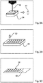
- Fig. 3A to Fig. 3D show the optional steps b1) to b3).
- a donor punch 30 is used to extract at least one tissue core 32 from the tissue sample block 34 (or donor block).
- tissue sample block 34 i.e. donor block with paraffin-embedded tissue sample
- the positions of the tissue cores to be removed may be chosen and indicated on the respective digital whole slide image. In this way, the coordinates of different tissue cores are available.
- the tissue microarray 36 may be created automatically.
- the extracted tissue cores 32 are arranged or reassembled in a microarray block 36 (or recipient block).
- tissue cores 32 and assembly in the microarray block 36 may require some feedback from the tissue sample block 34.
- tissue sample block 34 may be taken from the tissue sample block 34 after removal of the tissue cores 32.
- additional tissue cores may be added from reference samples to serve as a calibration reference for various intended staining reactions.
- tissue microarray slice 38 is created by cutting or sectioning the microarray block 36 into e.g. 4- to 5- micron thick sections.
- the tissue microarray slice 38 is supported by a transparent slide 40.
- the microarray slice 38 may be scanned to obtain a whole slide image of the microarray slice 38, or stored for later use.
- the microarray slice 38 may be stained with biomarkers according to the investigations at hand. This may be immune-, or in-situ hybridization (ISH) staining or any other special stain, or combinations thereof, in bright-field mode or in fluorescence. After the staining procedures, the microarray slice 38 is scanned to obtain a whole slide image of the stained microarray slice 38.
- biomarkers immune-, or in-situ hybridization (ISH) staining or any other special stain, or combinations thereof, in bright-field mode or in fluorescence.
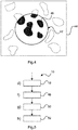
- Fig. 4 shows an example of step c) for registering a tissue core image 42 with a reference image 44.
- the tissue core image 42 relates to the image area that corresponds to the tissue core 32 (see Fig. 3C ) in the whole slide image of the microarray slice 38 (see Fig. 3C ).
- the reference image 44 may be acquired before or after removal of the tissue cores. In case the reference image 44 is taken after core removal, a careful extraction and assembly process may be needed, since only coordinates from the tissue cores can be used.
- the tissue core 32 is treated with a staining protocol for staining or colorizing features of interest 46 inside the tissue core 32.
- the features of interest 46 relates to the cytoplasm of tumor cells.
- the tissue core image 42 is registered with the reference image 46 based on the spatial arrangement of the respective tissue core within the tissue sample block.
- the spatial arrangement may be determined based on feature matching, on basis of coordinates, or a combination thereof.
- to register relates to arranging or positioning the tissue core image(s) on the corresponding positions on the reference image.
- the registration may be intensity-based or feature-based.
- Intensity-based methods compare intensity patterns in images via correlation metrics.
- Feature-based methods find correspondence between image features such as points, lines, contour or other features that are known in image analysis, which may be determined by intensity variations. Hence, the intensity-based methods may also be considered as feature-based methods.
- the registration may be done by detecting matching features between the tissue core image(s) and portion(s) (or sub-image) of the reference image.
- the tissue core image(s) may be rotated, translated, or stretched to match the corresponding potion(s) of the reference image. For example, for the image registration, at least some features (e.g. A, B, C) in the tissue core image(s) are projected onto similar features (e.g. A', B', C') in the corresponding portion(s) of the reference image.
- feature of interest relates to points, lines, and contours or other features that are known in image analysis.
- the features of interest may be associated with e.g. sub-structures of certain biological material (e.g. cytoplasma of tumor cells), a region of interest (e.g. region containing tissue) or a removing area (e.g. an area in which tissues are scraped off for the purpose of e.g. molecular diagnostic tests), etc.
- Fig. 5 shows a further option, according to which, the method 10 further comprises:
- the tissue microarray unit identifies which feature of interest in a core image may be extended according to step h), by determining whether the feature of interest is in contact with a border of the core image. If a contact exists, it may be an indication that a matching feature may exist in the periphery area on the reference image. The tissue microarray unit then analyzes the reference image in the periphery area at or around the contact position, to determine if a matching feature can actually be found in the reference image. The matching feature should also be in contact with the border of the core image at same position(s) than the feature of interest. The skilled person in the art will appreciate that some alternatives are possible.
- the tissue microarray unit may use the reference image instead of the core image, to detect the presence of contact between the border of the core image and a potential matching feature.
- a contact it may be an indication that a feature of interest in the core image may correspond to the potential matching feature and thus be the subject of an extension of a staining pattern according to step h).
- the extension of the staining pattern of the feature of interest within the registered tissue core images into the matching feature in the periphery area such that the staining pattern continues through and beyond a perimeter of the respective registered tissue core image may be implemented by analyzing in the core image the intensity of the pixels of the feature of interest that are in the vicinity of said border.
- the intensity of these pixels may serve as a basis for determining the intensity of the pixels constituting the extension of the staining pattern.
- the skilled person in the art will understand that there are many different possibilities for such determination, such as but not limited to calculating an average intensity of said pixels.
- the term "morphological information" relates to the appearance of the features inside the image, such as shape, structure, color, pattern, etc. Some morphological information may be obtained after the staining process.
- matching feature relates to points, lines, and contours in the periphery area on the reference image, which have similar morphological information as the feature of interest inside the tissue core image.
- the matching feature may also relate to the corresponding sub-structures in the periphery area.
- the matching feature may also relate to the region of interest.
- the extension also referred to as extrapolation of the staining pattern, relates to digitally coloring the matching feature with similar staining colors as the feature of interest.
- the intensity/transparency may be adapted to e.g. distance or the similarity between the matching feature and the feature of interest.
- the extension of the staining pattern into areas outside the tissue core area may facilitate manual scoring and interpretation.
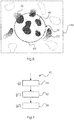
- Fig. 6 shows an example of extending staining pattern of Fig. 4 .
- Matching features 54 are identified that correspond to the features of interest 46.
- the matching features 54 also relate to cytoplasm of tumor cells, but outside the tissue core image 42.
- the corresponding features of interest outside the tissue core images i.e. the matching features
- This may support a user, e.g. a pathologist, in identifying the features of interest not only inside the tissue core images, but also in the areas outside, which thus facilitates e.g. manual scoring and interpretation.
- the periphery area may have a range.
- the features outside of the range are not further digitally stained or colorized.
- the range may be e.g. of the order of 1/100 the radius of the core to 2 times the radius or more.
- Fig.6 illustrates an embodiment of the invention which has not yet been discussed, wherein the tissue microarray analyzing unit has digitally stained a feature of interest 57 in the reference image that is not in contact with the border of the core image but still within a predefined distance from said border. Indeed, the tissue microarray analyzing unit has determined that this feature 57 has an architecture which is similar to a feature of interest present in the core image (not shown in Fig.6 ).
- the feature of interest may be a gland having an architecture with a well recognizable characteristic by the analyzing unit.
- one particular characteristic parameter may be used by the analyzing unit, such as but not limited to a cell density, nuclear size, stain intensity, nucleus cytoplasm ratio, cell shape, etc.
- step g) further comprises: g1) assigning 56 a quality index to the matching feature in the periphery area; and g2) determining 58 a range of the periphery area based on the assigned quality index.
- the quality index is assigned based on the similarity of the morphological information between the feature of interest and the matching feature.
- the staining pattern that extends into the matching features 54 has a transparency and/or intensity in dependence of: the assigned quality index and/or a distance from the registered tissue core image.
- the transparency and/or intensity of the matching features 54 may vary according to the distance to the registered tissue core image.
- the matching features 54 close to a boundary 60 of the tissue core image 42 may receive the same staining intensity as the features of interest 46 inside the tissue core image 42, whereas the matching features 54 away from the tissue core images may be gradually decreased.
- the intensity of the staining as projected or extended may be decreased with reduced assigned quality index assigned to the matching feature.
- nucleus of tumor cells may be assigned with a high quality index and thus high intensity
- cytoplasma of tumor cells may be assigned with a low quality index and thus low intensity.
- the quality index is related to the staining protocol applied on the sample slide. Thus, quality indices can be used to estimate the boundary or range for each biomarker separately.
- a user may identify the reliability of the feature extension (or feature matching) according to the respective intensity and/or transparency of matching features.
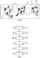
- Fig. 8 shows a further option, according to which, at least two tissue cores 38 (see examples in Fig. 3C ) are stained with different staining protocols (indicated with different patterns), and in step c), tissue core images 42 of the at least two tissue cores 38 are registered with the reference image 44.
- the tissue core images 42 may have different degrees of extension.
- staining protocol relates to a certain procedure applied to the tissue cores.
- to stain relates to coloring otherwise transparent tissue sections, thus allowing highly trained pathologists, for example, to view tissue morphology (structure) or to look for the presence or prevalence of particular cell types, structures or even microorganisms such as bacteria, proteins and nucleic acids.
- routine stain relates to H&E stain, or HE stain, which is one of the principal stains in pathology and is used "routinely” with all tissue specimens to reveal the underlying tissue structures and conditions.
- special stains relates to a large number of alternative staining techniques that are used when the H&E stain does not provide all the information the pathologist or researcher needs.
- periodic acid Schiff (PAS) staining is often used to stain kidney biopsies, liver biopsies, certain glycogen storage diseases in striated muscles and suspected fungal infections.
- advanced stains relates to methods of staining that use affinity-based binding reagents (Immunohistochemica) or ISH (In situ hybridization) to target specific proteins or DNA/RNA sequences, respectively.
- affinity-based binding reagents Immunohistochemica
- ISH In situ hybridization
- different IHC stains e.g. against ER, PR, Ki67 and HER2 protein
- multiple stains may be visualized on the same reference image simultaneously at the same and/or different positions.
- Displaying multiple cores may be used to indicate tumor heterogeneity and create a better overview of the whole tumor.
- a user may acquire staining information outside the tissue core areas and may end up at a more or less complete staining of the whole slide. These procedures may be repeated for each individual biomarker staining. As a result, the interpretation or manual scoring procedures may be facilitated.
- Fig. 9 shows a further option, according to which, the method 10 further comprises:
- the further microarray slice may be referred to as second microarray slice, whilst the microarray slice may be referred to as first microarray slice.
- multiple stains may also be visualized on different (e.g. consecutively) microarray slices at the same position (e.g. within the same tissue core).
- step c1) the further tissue core images are registered based on at least one of the previously registered tissue core images.
- each further microarray slice may take previous microarray slice as a reference when the staining contains sufficient information.
- An example of the staining is H-counterstaining.
- nuclear staining with e.g. 4',6-diamidino-2-phenylindole (DAPI) may be used.
- this option is to have multiple staining protocols for a number of slices from the same microarray block and to combine the images from those stains in a single image registered to the reference image.
- the results of the same tissue core may be displayed in a single image or a sequence of overlays that can be toggled or the like by a user.
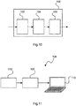
- Fig. 10 shows an example of an apparatus 100 for tissue examination.
- the apparatus comprises a data input 102, a tissue microarray analyzing unit 104, and an output 106.
- the data input 102 is configured to receive a reference image of a reference slice obtained from a tissue sample block; to receive a microarray image of a microarray slice comprising at least one tissue core obtained from at least the tissue sample block; and to provide the reference image and the microarray image to the tissue microarray analyzing unit.
- the data input 102 may be implemented in hardware, software, or a combination thereof.
- the tissue microarray analyzing unit 104 is configured to register tissue core images of at least one tissue core with the reference image based on a spatial arrangement of the respective tissue core within the tissue sample block.
- the tissue microarray analyzing unit 104 may also be implemented in hardware, software, or a combination thereof.
- the tissue microarray analyzing unit 104 may be e.g. a processing unit.
- the output 106 is configured to provide a registered result obtained from the tissue microarray analyzing unit for further analyzing purposes.
- the output 106 may also be implemented in hardware, software, or a combination thereof.
- the data input 102 may thus be referred to as data input interface, data input unit, or data input device, depending on the types of implementations.
- the output 106 may be referred to as output interface, output unit, or output device.
- the data input 102, the tissue microarray analyzing unit 104, and the output 106 may be implemented in a single, unitary device.
- the data input 102, the tissue microarray analyzing unit 104, and the output 106 may be separate devices, which are assembled in the apparatus 100.
- the at least one tissue core may be either stained e.g. with ISH dyes or unstained.
- the tissue microarray analyzing unit 104 is further configured to identify a feature of interest within the registered tissue core images based on morphological information of the registered tissue core image and to recognize a matching feature in a periphery area on the reference image based on the morphological information, wherein the periphery area surrounds the registered tissue core images.
- the tissue microarray analyzing unit 104 is also configured to extend a staining pattern of the feature of interest within the registered tissue core images into the matching feature in the periphery area such that the staining pattern continues through and beyond a perimeter of the registered tissue core images.
- Fig. 11 shows an example of a system 108 for tissue examination.
- the system comprises an image providing apparatus 110 and an apparatus for tissue examination according to one of the above-mentioned examples.
- the image providing apparatus 110 is configured to provide a reference image of a reference slice obtained from a tissue sample block.
- the image providing apparatus 110 is configured to provide a microarray image of a microarray slice comprising at least one tissue core obtained from at least the tissue sample block.
- the image providing apparatus 110 is also configured to provide the reference image and the microarray image to the apparatus for tissue examination.
- the image providing apparatus may comprise an image acquisition device, such as a digital pathology slide scanner or a microscope.
- the image providing apparatus may also comprise an image management system that allows for archival and intelligent retrieval either locally or remotely via the Internet.
- the image providing apparatus may comprise an image acquisition device e.g. for acquiring the microarray image of a microarray slice, and an image management system e.g. for providing a reference image that is previously stored in the image management system.
- a display 112 is provided.
- the display 112 is configured to display the registered tissue core images in combination with the reference image, e.g. in an overlaid manner, for analyzing purpose.
- the display 112 is illustrated as a computer screen in Fig. 11 , the display may also be an interactive user interface, e.g. a touch screen, for allowing a user to input further parameters to control the registration process.
- an interactive user interface e.g. a touch screen
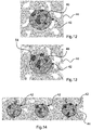
- FIG. 12, Fig. 13 and Fig. 14 show photographic images according to the drawings of Fig. 4 , Fig. 6 and Fig. 8 , respectively.
- the same reference numbers are indicated with respect to the Figs. 12 to 14 .
- a description with relation to Figs. 12 to 14 is thus not necessary.
- a computer program or a computer program element is provided that is characterized by being adapted to execute the method steps of the method according to one of the preceding embodiments, on an appropriate system.
- the computer program element might therefore be stored on a computer unit, which might also be part of an embodiment of the present invention.
- This computing unit may be adapted to perform or induce a performing of the steps of the method described above. Moreover, it may be adapted to operate the components of the above described apparatus.
- the computing unit can be adapted to operate automatically and/or to execute the orders of a user.
- a computer program may be loaded into a working memory of a data processor.
- the data processor may thus be equipped to carry out the method of the invention.
- This exemplary embodiment of the invention covers both, a computer program that right from the beginning uses the invention and a computer program that by means of an up-date turns an existing program into a program that uses the invention.
- the computer program element might be able to provide all necessary steps to fulfill the procedure of an exemplary embodiment of the method as described above.
- a computer readable medium such as a CD-ROM
- the computer readable medium has a computer program element stored on it which computer program element is described by the preceding section.
- a computer program may be stored and/or distributed on a suitable medium, such as an optical storage medium or a solid state medium supplied together with or as part of other hardware, but may also be distributed in other forms, such as via the internet or other wired or wireless telecommunication systems.
- a suitable medium such as an optical storage medium or a solid state medium supplied together with or as part of other hardware, but may also be distributed in other forms, such as via the internet or other wired or wireless telecommunication systems.
- the computer program may also be presented over a network like the World Wide Web and can be downloaded into the working memory of a data processor from such a network.
- a medium for making a computer program element available for downloading is provided, which computer program element is arranged to perform a method according to one of the previously described embodiments of the invention.
Description
- The present invention relates to the field of digital pathology, and in particular to an apparatus, to a system, and to a method for tissue examination. Furthermore, the invention relates to a computer program element as well as to a computer-readable medium.
- Pathology diagnostic investigation of patient material (e.g. tissue and cells) is the basis of many treatment decisions, e.g. in oncology. In standard anatomical pathology, diagnosis is made on the basis of cell morphology and staining characteristics. The investigation of the pathogenesis and progression of diseases, such as cancer, may require the use of multiple biomarkers for staining. The validation of these biomarkers using the standard histopathological techniques may be time-consuming and labor intensive.
- In recent years, tissue microarray has been proposed to overcome these problems. Tissue microarrays are paraffin blocks produced by extracting tissue cores from different paraffin donor blocks and re-embedding these into a single recipient (or microarray) block as an array. Therefore, a tissue microarray may allow high throughput analysis of multiple specimens at the same time. For example,
US 2009/0247416 A1 describes a method for analysis of tissue microarrays. However, analyzing images of tissue microarrays may be difficult e.g. with multiple tissue cores and/or multiple stains.WO2015063192 relates to a method of registration of two images of whole tissue slices. An unreliable area in the first image is determined and the registration is performed based on an area in the first image outside the unreliable area Other prior art documents disclosing imaging of tissue microarrays include: - W. Chen et al. - "Unsupervised Imaging, Registration and Archiving of Tissue Microarrays", Proc. Symposium of American Medical Informatics Association (AMIA), 2002, pp. 136-139
- M. Bello et al. - "Accurate Registration and Failure Detection in Tissue Microarray Images" - 5-th IEEE International Symposium on Biomedical Imaging, 14-05-2008, pp. 368-371.
- There may be a need to facilitate analyzing a tissue microarray.
- The object of the present invention is solved by the subject-matter of the independent claims, wherein further embodiments are incorporated in the dependent claims. It should be noted that the following described aspects of the invention apply also for the apparatus, for the system, and for the method for tissue examination, as well as for the computer program element and for the computer-readable medium.
- According to a first aspect of the present invention, an apparatus is provided for tissue examination. The apparatus comprises a data input, a tissue microarray analyzing unit, and an output. The data input is configured to receive a reference image of a reference slice obtained from a tissue sample block; to receive a microarray image of a microarray slice comprising at least one tissue core obtained from at least the tissue sample block; and to provide the reference image and the microarray image to the tissue microarray analyzing unit. The tissue microarray analyzing unit is configured to register tissue core images of at least one tissue core with the reference image based on a spatial arrangement of the respective tissue core within the tissue sample block. The output is configured to provide a registration result obtained from the tissue microarray analyzing unit for further analyzing purposes.
- As a result, the tissue core images are arranged at the corresponding positions in the reference image (e.g. whole slide image) of the tissue. This allows an operator, e.g. a pathologist, to interpret the staining results on the tissue cores in the context of the whole slide image of the tissue of origin.
- According to an example of the present invention, the tissue microarray analyzing unit is further configured to identify a feature of interest within the registered tissue core images based on morphological information of the registered tissue core image. Additionally, the tissue microarray analyzing unit is configured to recognize a matching feature in a periphery area on the reference image based on the morphological information, wherein the periphery area surrounds the respective registered tissue core image. Furthermore, the tissue microarray analyzing unit is configured to extend a staining pattern of the feature of interest within the registered tissue core images into the matching feature in the periphery area such that the staining pattern continues through and beyond a perimeter of the respective registered tissue core image.
- As a result, the extension, or extrapolation, of the staining results into areas outside the tissue core or tissue cores creates digital staining around the tissue cores, which may facilitate manual scoring and interpretation.
- According to a second aspect of the present invention, a system is provided for tissue examination. The system comprises an image providing apparatus and an apparatus for tissue examination according to one of the examples described above and in the following. The image providing apparatus is configured to provide a reference image of a reference slice obtained from a tissue sample block. The image providing apparatus is further configured to provide a microarray image of a microarray slice comprising at least one tissue core obtained from at least the tissue sample block. In addition, the image providing apparatus is configured to provide the reference image and the microarray image to the apparatus for tissue examination.
- As a result, the system allows a combination of the morphological information in the tissue core images and in the reference image, e.g. whole slide image, of the tissue of origin, thus making it easier to understand the context of the tissue core image in the whole sample, e.g. in the total tumor.
- According to an example of the present invention, the system further comprises a display. The display is configured to display the registered tissue core images in combination with the reference image for analyzing purpose.
- As a result, the registration results are visually presented to an operator, e.g. a pathologist, for better interpretation of staining results.
- According to a third aspect of the present invention, a method is provided for tissue examination. The method comprises the following steps:
- a) providing a reference image of a reference slice obtained from a tissue sample block;
- b) providing a microarray image of a microarray slice comprising at least one tissue core obtained from at least the tissue sample block;
- c) registering tissue core images of at least one tissue core with the reference image based on a spatial arrangement of the respective tissue core within the tissue sample block; and
- d) providing the registered tissue core images in combination with the reference image for analyzing purposes.
- As a result, this may facilitate understanding the context of the tissue cores in the total tissue.
- The combination may be realized in several methods. For example, the registered tissue core images are combined with the reference image in an overlaid manner. In a further example, the registered tissue core images are inserted into the reference image.
- According to an example of the present invention, for step a) it is provided:
- a1) generating the reference slice from the tissue sample block; and
- a2) generating an image from the reference slice as the reference image.
- In step a1), the reference slice may be stained e.g. with hematoxylin and eosin (H&E) dyes, before generating an image to enhance contrast and make certain morphological features visible. For example, the reference image is a whole slide image of the tissue to be examined.
- According to an example of the present invention, for step b) it is provided:
- b1) creating a microarray block comprising at least one tissue core arranged within a block structure;
- b2) generating at least one microarray slice of the microarray block; and
- b3) generating an image of the microarray slice as the tissue microarray image.
- According to an example of the present invention, in step b2) the at least one microarray slice is stained. Optionally, the at least one microarray slice is stained differently than the reference slice.
- In other words, the at least one microarray slice may be stained with at least one staining protocol for visualizing morphological information of certain features of interest. Also biomarkers, such as proteins or nucleic acids, may be staining targets.
- According to an example of the present invention, the method further comprises:
- f) identifying a feature of interest within the registered tissue core images based on morphological information of the registered tissue core image;
- g) recognizing a matching feature in a periphery area on the reference image based on the morphological information, wherein the periphery area surrounds the respective registered tissue core image; and
- h) extending a staining pattern of the feature of interest within the registered tissue core images into the matching feature in the periphery area such that the staining pattern continues through and beyond a perimeter of the respective registered tissue core image.
- By extending the staining pattern into the periphery area around the tissue core images, the matching features outside the tissue cores are also colorized or marked. This may allow a user, e.g. pathologist, to identify features of interest not only inside but also outside the tissue core images. In other words, the extension of the staining pattern may enlarge the staining results, thus facilitating e.g. manual scoring and interpretation of certain features.
- According to an example of the present invention, step g) further comprises:
- g1) assigning a quality index to the matching feature in the periphery area; and
- g2) determining a range of the periphery area based on the assigned quality index.
- In other words, the range of extension (or extrapolation) is determined by the quality index that may relate to the reliability of the feature matching. This allows a user to control the extent of feature matching process outside the tissue core images.
- According to an example of the present invention, the staining pattern that extends into the matching feature has a transparency and/or intensity in dependence of:
- the assigned quality index; and/or
- a distance from the registered tissue core image.
- In an example, the intensity can be varied gradually with increasing distance from the tissue cores. The reduction of intensity may also depend on the quality index related to the reliability of feature extension. As a result, a user (e.g. a pathologist) may identify the reliability of the feature extension (or feature matching) according to the respective intensity and/or transparency of matching features.
- According to an example of the present invention, at least two tissue cores are stained with different staining protocols. In step c), tissue core images of the at least two tissue cores are registered with the reference image.
- As a result, multiple stains can be visualized and analyzed on the same reference image (e.g. whole slide image) simultaneously at different positions. This may facilitate e.g. sub-typing tumors for oncology diagnostics. Taking multiple cores at different positions may also be helpful e.g. for understanding the heterogeneous aspect of the tumors.
- According to an example of the present invention, the method further comprises:
- b4) providing a further microarray image of a further microarray slice obtained from the microarray block, wherein the further microarray slice is stained differently from the microarray slice; and
- c1) registering further tissue core images of at least one of the tissue cores of the further microarray image with the reference image.
- The microarray slice is also referred to as first microarray slice, whilst the further microarray slice is also referred to as second microarray slice.
- In other words, consecutive slides may receive different staining, and/or staining for different biomarkers. As a result, it is possible to stain the same tissue core with different staining protocol for better understanding pathological information.
- According to an example of the present invention, in step c1), the further tissue core images are registered based on at least one of the previously registered tissue core images.
- Since certain information, such as the orientation of an individual tissue core with respect to the direction of the tissue microarray, remains unchanged (or nearly unchanged) for all slices from the same microarray block, such information may be used for improving the matching process.
- According to a fourth aspect of the invention, a computer program element is provided for controlling an apparatus according to one of the embodiments described above and in the following, which, when being executed by a processing unit, is adapted to perform the inventive method.
- According to a fifth aspect of the invention, a computer readable medium is provided having stored the program element.
- The term "reference image" may also be referred to as "whole slide image", digital image or digital slide. A reference image relates to image data created from (e.g. glass) slides using a scanning device. Reference images (whole slide images, digital images or digital slides) may be directly provided by a scanning device, like a desktop slide scanner. Alternatively, reference images may be provided by an image management system that allows for archival and intelligent retrieval either locally or remotely via the Internet.
- The term "tissue sample block", also referred to as donor block, relates to tissue, obtained from a region of a human or non-human. The tissue sample block may be obtained from a living organism, or also from a non-living (dead) organism, which may be embedded in paraffin for later use. For example, depending on a suspected cancer type, tissue sample block may be obtained in different ways such as punch/core biopsy, excisional/incisional biopsy, resection, etc.
- The term "sample slice" or "slice" relates to a thin slice of the pathological sample block, which is obtained by sectioning the paraffin-embedded pathological sample block (after e.g. chemical fixation, processing and embedding procedures) into thin slices (thickness may relate to an order of a few micrometers).
- The term "sample slide" relates to a carrier provided for supporting (and thus carrying) sample slices for imaging purposes, and also for archive purposes for storing sample slices. In an example, the sample slide comprises a glass substrate onto which the sample slice is provided. A cover, for example a thin glass or polymer layer or plate may be provided to protect and hold the sample slice.
- The term "microarray block", also referred to as recipient block, relates to arrays of tissue cores that may belong to and come from different positions in the same tissue sample block and/or from different tissue sample blocks.
- The term "tissue core" relates to the sample sections inside the microarray block. Tissue cores may be punched out from the tissue sample block (or donor block) at different positions and arranged in the microarray block (or recipient block) in a regular pattern. Tissue cores may have a diameter of 0.6 to 2 mm, or any other suitable value. Hence, a microarray block may comprise hundreds of tissue cores in form of spots on a single slide. For example, the tissue core is also referred to as tissue core, in case the sample sections being tissue sections.
- The term "microarray slice" relates to a thin slice of the microarray block, which is obtained by sectioning the microarray block into thin slices.
- The term "microarray image" relates to the image data created from the microarray slice using a digital image acquisition or scanning device. The microarray image may comprise and/or be linked to a separate file containing annotations to keep track of various images and samples of origin within each image.
- According to an aspect of the present invention, the images of the tissue cores of tissue microarrays are registered with the original whole slide image of the tissue at the corresponding positions. The registration of images of the tissue cores with the original whole slide image may facilitate understanding the context of the tissue cores in the total tissue, e.g. a total tumor. Registration may involve in-plane displacement, rotation and stretching of the images in order to obtain a minimum number of matching features between the image and the reference image. The number of matching features can be between 50 and 500 or another desired number.
- The display of the registered images allows the user to toggle between the view of the reference image and that of the corresponding tissue core that provides the result of a different staining procedure. Multiple staining images can be available from the same core all registered to each other so that the user can toggle between the different images. Alternatively, a semi-transparent image can be overlaid on a reference image to assist the interpretation of the observations. Optionally, a digital staining may be carried out in the areas outside the images of the tissue cores such that the staining pattern of the tissue cores is extended into the periphery area of the registered reference image. The digital staining intensity may be faded (i.e. increased transparency) with increasing uncertainty and/or distance from the tissue core to which it is related. The extension of staining pattern may facilitate manual scoring and interpretation. As a further option, multiple cores at different positions and/or multiple stains may be registered together with the original whole slide image e.g. for understanding heterogeneous aspect of tumors, for sub-typing tumors for oncology diagnostics, or for any other analyzing purposes.
- The reference image can be preferably a hematoxylin and eosin stain (H&E) stained tissue section of the patient sample. This section is preferably acquired before the manufacture of the micro-array. The positions of the cores to be extracted from the donor tissue block can be determined on the reference image. The coordinates of the core positions can be stored in a file and used as a starting position for the registration of the images from the respective cores to the reference image. The sections containing the array of cores are subjected to different, preferably biomarker directed staining assays, for instance for subtyping a tumor and obtaining information that supports the diagnosing a patient case.
- The images of cores corresponding to the same tissue block of origin can be combined in a single image and registered to the reference image. This can be images from different stains. The virtual staining outside the area of the core can be a combined staining from different images to represent a combination of information. As an example one can combine a cell membrane staining for instance for human epidermal growth factor receptor 2 (HER2) with a nuclear staining, for instance for estrogen receptors (ER) and optionally combine that with a Fluorescence in Situ Hybridization (FISH) staining for Her2-neu gene amplification in a breast tumor sample. In this way all information can be displayed in a single view with the possibility to highlight or dim each of the stains individually. By overlaying and extending the stain outside the core area the pathologist gets a better impression of the tumor properties. By highlighting or dimming staining images in an overlay a virtual staining is presented also in the core area in addition to the area surrounding the core. The virtual staining can use different colors than the original stains to facilitate viewing overlapping areas.
- These and other aspects of the present invention will become apparent from and be elucidated with reference to the embodiments described hereinafter.
- Exemplary embodiments of the invention will be described in the following with reference to the following drawings:
-
Fig. 1 shows an example of a method for tissue examination. -
Fig. 2 shows a further example of a method for tissue examination. -
Figs. 3A to 3B show a schematic illustration ofFig. 2 . -
Fig. 4 shows an example for registering a tissue core image with a reference image. -
Fig. 5 shows another example of a method for tissue examination. -
Fig. 6 shows an example of extending staining pattern ofFig. 4 . -
Fig. 7 shows a further example of a method for tissue examination. -
Fig. 8 shows a still further example of a method for tissue examination. -
Fig. 9 shows another example of a method for tissue examination. -
Fig. 10 shows a schematic setup of an example of an apparatus for tissue examination. -
Fig. 11 shows a schematic setup of an example of a system for tissue examination. -
Fig. 12, Fig. 13 and Fig. 14 show photographic images of the embodiments ofFig. 4 ,Fig. 6 andFig. 8 respectively. - The figures are only schematically illustrated and not to scale. Same reference signs refer to same or similar features throughout the figures.
-
Fig. 1 shows basic steps of amethod 10 for tissue examination. The method comprises the following steps: - In a
first step 12, also referred to as step a), a reference image of a reference slice obtained from a tissue sample block is provided. - In a
second step 14, also referred to as step b), a microarray image of a microarray slice comprising at least one tissue core obtained from at least the tissue sample block is provided. - In a
third step 16, also referred to as step c), tissue core images of the at least one tissue core are registered with the reference image based on a spatial arrangement of the respective tissue core within the tissue sample block. - In a
fourth step 18, also referred to as step d), the registered tissue core images are provided in combination with the reference image for analyzing purposes. - In step a), the reference image may be previously stored in an image management system, which allows for retrieval either locally or remotely. The reference image may also be directly provided by an image acquisition device, such as a desktop slide scanner.
-
Fig. 2 shows an option, according to which, for step a) it is provided: a1) generating 20 the reference image slice from the tissue sample block; and a2) generating 22 an image from the reference slice as the reference image. The optional steps a1) and a2) are indicated inFig. 2 by a dotted line. - In step a1), the reference slice may be stained e.g. with H&E stain, before generating an image to enhance contrast and make morphological features visible.
- In step b), the microarray image may also be previously stored in an image management. Alternatively, the microarray image may be provided by an image acquisition device.
- It is noted that the alphabet symbols (letters) used for the method steps, are used to differentiate the method steps, which symbols, however, are not meant to limit the order of the method steps to the alphabet sequence. For example, the reference image may also be taken after the removal of the tissue cores. In other words, tissue examination may also be carried out based on the following sequential steps: b)-a)-c)-d).
- Also illustrated in
Fig. 2 is a further option, according to which, for step b), it is provided: b1) creating 24 a microarray block comprising at least one tissue core arranged within a block structure; b2) generating 26 at least one microarray slice of the microarray block; and b3) generating 28 an image of the microarray slice as the tissue microarray image. The optional steps b1) to b3) are also indicated inFig. 2 by a dotted line. - In step b2) the at least one microarray slice may be stained. Optionally, the at least one microarray slice is stained differently than the reference slice.
- In other words, the microarray slice may optionally be treated with a staining protocol, e.g. for assessing the signaling proteins or molecular biomarkers of cancer.
-
Fig. 3A to Fig. 3D show the optional steps b1) to b3). - In
Fig. 3A , adonor punch 30 is used to extract at least onetissue core 32 from the tissue sample block 34 (or donor block). - Optionally, digital whole slide images of H&E stained slices obtained from the
tissue sample block 34, i.e. donor block with paraffin-embedded tissue sample, may be acquired before the punching process. The positions of the tissue cores to be removed may be chosen and indicated on the respective digital whole slide image. In this way, the coordinates of different tissue cores are available. Thus, thetissue microarray 36 may be created automatically. - In
Fig. 3B , the extractedtissue cores 32 are arranged or reassembled in a microarray block 36 (or recipient block). - The production of the
tissue cores 32 and assembly in themicroarray block 36 may require some feedback from thetissue sample block 34. For example, for verification, digital whole slide images may be taken from thetissue sample block 34 after removal of thetissue cores 32. Although not illustrated, as an option, additional tissue cores may be added from reference samples to serve as a calibration reference for various intended staining reactions. - In
Fig. 3C , at least onetissue microarray slice 38 is created by cutting or sectioning themicroarray block 36 into e.g. 4- to 5- micron thick sections. Thetissue microarray slice 38 is supported by atransparent slide 40. Themicroarray slice 38 may be scanned to obtain a whole slide image of themicroarray slice 38, or stored for later use. - Optionally, the
microarray slice 38 may be stained with biomarkers according to the investigations at hand. This may be immune-, or in-situ hybridization (ISH) staining or any other special stain, or combinations thereof, in bright-field mode or in fluorescence. After the staining procedures, themicroarray slice 38 is scanned to obtain a whole slide image of the stainedmicroarray slice 38. -
Fig. 4 shows an example of step c) for registering atissue core image 42 with areference image 44. - The
tissue core image 42 relates to the image area that corresponds to the tissue core 32 (seeFig. 3C ) in the whole slide image of the microarray slice 38 (seeFig. 3C ). Thereference image 44 may be acquired before or after removal of the tissue cores. In case thereference image 44 is taken after core removal, a careful extraction and assembly process may be needed, since only coordinates from the tissue cores can be used. - Also illustrated as an option in
Fig. 4 , thetissue core 32 is treated with a staining protocol for staining or colorizing features ofinterest 46 inside thetissue core 32. In this example, the features ofinterest 46 relates to the cytoplasm of tumor cells. - The
tissue core image 42 is registered with thereference image 46 based on the spatial arrangement of the respective tissue core within the tissue sample block. The spatial arrangement may be determined based on feature matching, on basis of coordinates, or a combination thereof. - The term "to register" relates to arranging or positioning the tissue core image(s) on the corresponding positions on the reference image. The registration may be intensity-based or feature-based.
- Intensity-based methods compare intensity patterns in images via correlation metrics.
- Feature-based methods find correspondence between image features such as points, lines, contour or other features that are known in image analysis, which may be determined by intensity variations. Hence, the intensity-based methods may also be considered as feature-based methods. The registration may be done by detecting matching features between the tissue core image(s) and portion(s) (or sub-image) of the reference image. The tissue core image(s) may be rotated, translated, or stretched to match the corresponding potion(s) of the reference image. For example, for the image registration, at least some features (e.g. A, B, C) in the tissue core image(s) are projected onto similar features (e.g. A', B', C') in the corresponding portion(s) of the reference image.
- The term "feature of interest" relates to points, lines, and contours or other features that are known in image analysis. The features of interest may be associated with e.g. sub-structures of certain biological material (e.g. cytoplasma of tumor cells), a region of interest (e.g. region containing tissue) or a removing area (e.g. an area in which tissues are scraped off for the purpose of e.g. molecular diagnostic tests), etc.
-
Fig. 5 shows a further option, according to which, themethod 10 further comprises: - f) identifying 48 a feature of interest within the registered tissue core images based on morphological information of the registered tissue core image;
- g) recognizing 50 a matching feature in an periphery area on the reference image based on the morphological information, wherein the periphery area surrounds the respective registered tissue core image; and
- h) extending 52 a staining pattern of the feature of interest within the registered tissue core images into the matching feature in the periphery area such that the staining pattern continues through and beyond a perimeter of the respective registered tissue core image.
- In embodiments related to this option, the tissue microarray unit identifies which feature of interest in a core image may be extended according to step h), by determining whether the feature of interest is in contact with a border of the core image. If a contact exists, it may be an indication that a matching feature may exist in the periphery area on the reference image. The tissue microarray unit then analyzes the reference image in the periphery area at or around the contact position, to determine if a matching feature can actually be found in the reference image. The matching feature should also be in contact with the border of the core image at same position(s) than the feature of interest. The skilled person in the art will appreciate that some alternatives are possible. For instance, the tissue microarray unit may use the reference image instead of the core image, to detect the presence of contact between the border of the core image and a potential matching feature. When a contact is detected, it may be an indication that a feature of interest in the core image may correspond to the potential matching feature and thus be the subject of an extension of a staining pattern according to step h).
- The extension of the staining pattern of the feature of interest within the registered tissue core images into the matching feature in the periphery area such that the staining pattern continues through and beyond a perimeter of the respective registered tissue core image may be implemented by analyzing in the core image the intensity of the pixels of the feature of interest that are in the vicinity of said border. The intensity of these pixels may serve as a basis for determining the intensity of the pixels constituting the extension of the staining pattern. The skilled person in the art will understand that there are many different possibilities for such determination, such as but not limited to calculating an average intensity of said pixels. The term "morphological information" relates to the appearance of the features inside the image, such as shape, structure, color, pattern, etc. Some morphological information may be obtained after the staining process.
- The term "matching feature" relates to points, lines, and contours in the periphery area on the reference image, which have similar morphological information as the feature of interest inside the tissue core image. For example, if the feature of interest relates to sub-structures of certain biological material such as cytoplasma of tumor cells, the matching feature may also relate to the corresponding sub-structures in the periphery area. In a further example, in case the feature of interest relates to a region of interest, such as the region containing tissue, the matching feature may also relate to the region of interest.
- The extension, also referred to as extrapolation of the staining pattern, relates to digitally coloring the matching feature with similar staining colors as the feature of interest. If desired, the intensity/transparency may be adapted to e.g. distance or the similarity between the matching feature and the feature of interest. The extension of the staining pattern into areas outside the tissue core area may facilitate manual scoring and interpretation.
-
Fig. 6 shows an example of extending staining pattern ofFig. 4 . - Matching features 54 are identified that correspond to the features of
interest 46. In this example, the matching features 54 also relate to cytoplasm of tumor cells, but outside thetissue core image 42. - In this way, the corresponding features of interest outside the tissue core images, i.e. the matching features, can be digitally stained or marked. This may support a user, e.g. a pathologist, in identifying the features of interest not only inside the tissue core images, but also in the areas outside, which thus facilitates e.g. manual scoring and interpretation.
- The periphery area may have a range. In other words, the features outside of the range are not further digitally stained or colorized. The range may be e.g. of the order of 1/100 the radius of the core to 2 times the radius or more.
- Further,
Fig.6 illustrates an embodiment of the invention which has not yet been discussed, wherein the tissue microarray analyzing unit has digitally stained a feature ofinterest 57 in the reference image that is not in contact with the border of the core image but still within a predefined distance from said border. Indeed, the tissue microarray analyzing unit has determined that thisfeature 57 has an architecture which is similar to a feature of interest present in the core image (not shown inFig.6 ). By way of a non-limitative example, the feature of interest may be a gland having an architecture with a well recognizable characteristic by the analyzing unit. Depending on the type of feature of interest, one particular characteristic parameter may be used by the analyzing unit, such as but not limited to a cell density, nuclear size, stain intensity, nucleus cytoplasm ratio, cell shape, etc. -
Fig. 7 shows a further option, according to which, step g) further comprises: g1) assigning 56 a quality index to the matching feature in the periphery area; and g2) determining 58 a range of the periphery area based on the assigned quality index. - In an example, the quality index is assigned based on the similarity of the morphological information between the feature of interest and the matching feature.
- In a further example, other measures, such as the similarity of the tissue as a whole, may be used for determining the quality index.
- Referring now to
Fig. 6 , as a further option, the staining pattern that extends into the matching features 54 has a transparency and/or intensity in dependence of: the assigned quality index and/or a distance from the registered tissue core image. - For example, as shown in
Fig. 6 , the transparency and/or intensity of the matching features 54 may vary according to the distance to the registered tissue core image. In other words, the matching features 54 close to aboundary 60 of thetissue core image 42 may receive the same staining intensity as the features ofinterest 46 inside thetissue core image 42, whereas the matching features 54 away from the tissue core images may be gradually decreased. - In a further example, not further shown, the intensity of the staining as projected or extended may be decreased with reduced assigned quality index assigned to the matching feature. For example, nucleus of tumor cells may be assigned with a high quality index and thus high intensity, whereas cytoplasma of tumor cells may be assigned with a low quality index and thus low intensity. In a further example, the quality index is related to the staining protocol applied on the sample slide. Thus, quality indices can be used to estimate the boundary or range for each biomarker separately.
- In this way, a user may identify the reliability of the feature extension (or feature matching) according to the respective intensity and/or transparency of matching features.
-
Fig. 8 shows a further option, according to which, at least two tissue cores 38 (see examples inFig. 3C ) are stained with different staining protocols (indicated with different patterns), and in step c),tissue core images 42 of the at least twotissue cores 38 are registered with thereference image 44. - Optionally, the
tissue core images 42 may have different degrees of extension. - The term "staining protocol" relates to a certain procedure applied to the tissue cores. The term "to stain" relates to coloring otherwise transparent tissue sections, thus allowing highly trained pathologists, for example, to view tissue morphology (structure) or to look for the presence or prevalence of particular cell types, structures or even microorganisms such as bacteria, proteins and nucleic acids.
- Various staining protocols will be appreciated, including for example routine stains, special stains, and advanced stains.
- The term "routine stain" relates to H&E stain, or HE stain, which is one of the principal stains in pathology and is used "routinely" with all tissue specimens to reveal the underlying tissue structures and conditions.
- The term "special stains" relates to a large number of alternative staining techniques that are used when the H&E stain does not provide all the information the pathologist or researcher needs. For example, periodic acid Schiff (PAS) staining is often used to stain kidney biopsies, liver biopsies, certain glycogen storage diseases in striated muscles and suspected fungal infections.
- The term "advanced stains" relates to methods of staining that use affinity-based binding reagents (Immunohistochemica) or ISH (In situ hybridization) to target specific proteins or DNA/RNA sequences, respectively. For example, in case of breast cancer diagnosis, different IHC stains (e.g. against ER, PR, Ki67 and HER2 protein) may be used to determine the exact sub-type of cancer.
- In this way, multiple stains may be visualized on the same reference image simultaneously at the same and/or different positions. Displaying multiple cores may be used to indicate tumor heterogeneity and create a better overview of the whole tumor. By optionally extending the staining pattern, a user may acquire staining information outside the tissue core areas and may end up at a more or less complete staining of the whole slide. These procedures may be repeated for each individual biomarker staining. As a result, the interpretation or manual scoring procedures may be facilitated.
-
Fig. 9 shows a further option, according to which, themethod 10 further comprises: - b4) providing 62 a further microarray image of a further microarray slice obtained from the microarray block, the further microarray slice is stained differently from the microarray slice; and
- c1) registering 64 further tissue core images of at least one tissue cores of the further microarray image with the reference image.
- The further microarray slice may be referred to as second microarray slice, whilst the microarray slice may be referred to as first microarray slice.
- In other words, multiple stains may also be visualized on different (e.g. consecutively) microarray slices at the same position (e.g. within the same tissue core).
- Optionally, in step c1), the further tissue core images are registered based on at least one of the previously registered tissue core images.
- This is because certain information, such as orientation of an individual tissue core with respect to the direction of the tissue microarray, is same (or almost same) for all microarray slices from the same microarray block (or recipient block). This information may thus be used for improving the registration process. For example, by assuming the same rotational orientation of all tissue core images from the same position, information gained from one tissue core image may be used to reorient further or another tissue core image from the same tissue core.
- Registration of the tissue core images to the reference image may e.g. be done in the order of slicing (or sectioning), each further microarray slice may take previous microarray slice as a reference when the staining contains sufficient information. An example of the staining is H-counterstaining. In case of fluorescence staining, nuclear staining with e.g. 4',6-diamidino-2-phenylindole (DAPI) may be used.
- It is thus possible to do two different staining protocols on two consecutive microarray slices and then combine the results for the same core and optionally overlay it with the reference image to extend into the surrounding. In other words, this option is to have multiple staining protocols for a number of slices from the same microarray block and to combine the images from those stains in a single image registered to the reference image. In this way, the results of the same tissue core may be displayed in a single image or a sequence of overlays that can be toggled or the like by a user.
- Hence, as an additional or alternative option in
Fig. 8 , it is possible to have different stains on the same core by combining different staining protocols on two consecutive microarray slices (not further shown). - Of course one can do both, i.e. to have multiple staining protocols and register and display the results for all core positions from the same sample. In other words, as a further option, it is possible to combine the options as shown in
Fig. 8 and Fig. 9 . - It is also noted that some examples relating to the method steps may be combined. For example, as indicated above, it is possible to show multiple stains from different cores in a single representation on the reference image with digital staining. Other combinations are also contemplated in this application.
-
Fig. 10 shows an example of anapparatus 100 for tissue examination. The apparatus comprises adata input 102, a tissuemicroarray analyzing unit 104, and anoutput 106. - The
data input 102 is configured to receive a reference image of a reference slice obtained from a tissue sample block; to receive a microarray image of a microarray slice comprising at least one tissue core obtained from at least the tissue sample block; and to provide the reference image and the microarray image to the tissue microarray analyzing unit. Thedata input 102 may be implemented in hardware, software, or a combination thereof. - The tissue
microarray analyzing unit 104 is configured to register tissue core images of at least one tissue core with the reference image based on a spatial arrangement of the respective tissue core within the tissue sample block. Likewise, the tissuemicroarray analyzing unit 104 may also be implemented in hardware, software, or a combination thereof. For example, the tissuemicroarray analyzing unit 104 may be e.g. a processing unit. - The
output 106 is configured to provide a registered result obtained from the tissue microarray analyzing unit for further analyzing purposes. Theoutput 106 may also be implemented in hardware, software, or a combination thereof. - The
data input 102 may thus be referred to as data input interface, data input unit, or data input device, depending on the types of implementations. Likewise, theoutput 106 may be referred to as output interface, output unit, or output device. - In an example, the
data input 102, the tissuemicroarray analyzing unit 104, and theoutput 106 may be implemented in a single, unitary device. - In a further example, the
data input 102, the tissuemicroarray analyzing unit 104, and theoutput 106 may be separate devices, which are assembled in theapparatus 100. - It is also noted that the at least one tissue core may be either stained e.g. with ISH dyes or unstained.
- If the at least one tissue is stained, as an option, the tissue
microarray analyzing unit 104 is further configured to identify a feature of interest within the registered tissue core images based on morphological information of the registered tissue core image and to recognize a matching feature in a periphery area on the reference image based on the morphological information, wherein the periphery area surrounds the registered tissue core images. The tissuemicroarray analyzing unit 104 is also configured to extend a staining pattern of the feature of interest within the registered tissue core images into the matching feature in the periphery area such that the staining pattern continues through and beyond a perimeter of the registered tissue core images. -
Fig. 11 shows an example of asystem 108 for tissue examination. The system comprises animage providing apparatus 110 and an apparatus for tissue examination according to one of the above-mentioned examples. - The
image providing apparatus 110 is configured to provide a reference image of a reference slice obtained from a tissue sample block. In addition, theimage providing apparatus 110 is configured to provide a microarray image of a microarray slice comprising at least one tissue core obtained from at least the tissue sample block. Theimage providing apparatus 110 is also configured to provide the reference image and the microarray image to the apparatus for tissue examination. - In an example, the image providing apparatus may comprise an image acquisition device, such as a digital pathology slide scanner or a microscope.
- In a further example, the image providing apparatus may also comprise an image management system that allows for archival and intelligent retrieval either locally or remotely via the Internet.
- In a still further example, the image providing apparatus may comprise an image acquisition device e.g. for acquiring the microarray image of a microarray slice, and an image management system e.g. for providing a reference image that is previously stored in the image management system.
- Also shown in
Fig. 11 as an option, adisplay 112 is provided. Thedisplay 112 is configured to display the registered tissue core images in combination with the reference image, e.g. in an overlaid manner, for analyzing purpose. - Although the
display 112 is illustrated as a computer screen inFig. 11 , the display may also be an interactive user interface, e.g. a touch screen, for allowing a user to input further parameters to control the registration process. - For a better understanding,
Fig. 12, Fig. 13 and Fig. 14 show photographic images according to the drawings ofFig. 4 ,Fig. 6 andFig. 8 , respectively. Hence, the same reference numbers are indicated with respect to theFigs. 12 to 14 . In order to avoid unnecessary repetition, a description with relation toFigs. 12 to 14 is thus not necessary. - In another exemplary embodiment of the present invention, a computer program or a computer program element is provided that is characterized by being adapted to execute the method steps of the method according to one of the preceding embodiments, on an appropriate system.
- The computer program element might therefore be stored on a computer unit, which might also be part of an embodiment of the present invention. This computing unit may be adapted to perform or induce a performing of the steps of the method described above. Moreover, it may be adapted to operate the components of the above described apparatus. The computing unit can be adapted to operate automatically and/or to execute the orders of a user. A computer program may be loaded into a working memory of a data processor. The data processor may thus be equipped to carry out the method of the invention.
- This exemplary embodiment of the invention covers both, a computer program that right from the beginning uses the invention and a computer program that by means of an up-date turns an existing program into a program that uses the invention.
- Further on, the computer program element might be able to provide all necessary steps to fulfill the procedure of an exemplary embodiment of the method as described above.
- According to a further exemplary embodiment of the present invention, a computer readable medium, such as a CD-ROM, is presented wherein the computer readable medium has a computer program element stored on it which computer program element is described by the preceding section.
- A computer program may be stored and/or distributed on a suitable medium, such as an optical storage medium or a solid state medium supplied together with or as part of other hardware, but may also be distributed in other forms, such as via the internet or other wired or wireless telecommunication systems.
- However, the computer program may also be presented over a network like the World Wide Web and can be downloaded into the working memory of a data processor from such a network. According to a further exemplary embodiment of the present invention, a medium for making a computer program element available for downloading is provided, which computer program element is arranged to perform a method according to one of the previously described embodiments of the invention.
- It has to be noted that embodiments of the invention are described with reference to different subject matters. In particular, some embodiments are described with reference to method type claims whereas other embodiments are described with reference to the device type claims. However, a person skilled in the art will gather from the above and the following description that, unless otherwise notified, in addition to any combination of features belonging to one type of subject matter also any combination between features relating to different subject matters is considered to be disclosed with this application. However, all features can be combined providing synergetic effects that are more than the simple summation of the features.
- While the invention has been illustrated and described in detail in the drawings and foregoing description, such illustration and description are to be considered illustrative or exemplary and not restrictive. The invention is not limited to the disclosed embodiments. Other variations to the disclosed embodiments can be understood and effected by those skilled in the art in practicing a claimed invention, from a study of the drawings, the disclosure, and the dependent claims.
- In the claims, the word "comprising" does not exclude other elements or steps, and the indefinite article "a" or "an" does not exclude a plurality. A single processor or other unit may fulfill the functions of several items re-cited in the claims. The mere fact that certain measures are re-cited in mutually different dependent claims does not indicate that a combination of these measures cannot be used to advantage. Any reference signs in the claims should not be construed as limiting the scope.
Claims (11)
- An apparatus (100) for tissue examination, comprising:- a data input (102);- a tissue microarray analyzing unit (104); and- an output (106);wherein the tissue microarray analyzing unit is further configured to identify at least one feature of interest within the registered tissue core image based on morphological information of the registered tissue core image; to recognize a matching feature in a periphery area on the reference image based on the morphological information, wherein the periphery area surrounds the registered tissue core image; and to extend a staining pattern of the feature of interest within the registered tissue core image into the matching feature in the periphery area such that the staining pattern continues through and beyond a perimeter of the registered tissue core image.
wherein the data input is configured to receive a reference image of a reference slice obtained from a tissue sample block; to receive a microarray image of a microarray slice comprising at least one tissue core obtained from at least the tissue sample block; and to provide the reference image and the microarray image to the tissue microarray analyzing unit;
wherein the tissue microarray analyzing unit is configured to register a tissue core image of at least one tissue core with the reference image based on a spatial arrangement of the respective tissue core within the tissue sample block; and
wherein the output is configured to provide a registered result obtained from the tissue microarray analyzing unit for further analyzing purposes; - A system (108) for tissue examination, comprising:- an image providing apparatus (110); and- an apparatus for tissue examination according to one of the preceding claim;
wherein the image providing apparatus is configured to provide a reference image of a reference slice obtained from a tissue sample block; to provide a microarray image of a microarray slice comprising at least one tissue core obtained from at least the tissue sample block; and to provide the reference image and the microarray image to the apparatus for tissue examination. - System according to claim 2, further comprising:- a display (112);
wherein the display is configured to display the registered tissue core image in combination with the reference image for analyzing purposes. - A method (10) for tissue examination comprising the following steps:a) providing (12) a reference image of a reference slice obtained from a tissue sample block;b) providing (14) a microarray image of a microarray slice comprising at least one tissue core obtained from at least the tissue sample block;c) registering (16) a tissue core image of the at least one tissue core with the reference image based on a spatial arrangement of the respective tissue core within the tissue sample block;d) providing (18) the registered tissue core image in combination with the reference image for analyzing purposes,e) identifying (48) a feature of interest within the registered tissue core image based on morphological information of the registered tissue core image;f) recognizing (50) a matching feature in an periphery area on the reference image based on the morphological information, wherein the periphery area surrounds the respective registered tissue core image; andg) extending (52) a staining pattern of the feature of interest within the registered tissue core image into the matching feature in the periphery area such that the staining pattern continues through and beyond a perimeter of the respective registered tissue core image.
- Method according to claim 4, wherein for step a) it is provided:a1) generating (20) the reference slice from the tissue sample block; anda2) generating (22) an image from the reference slice as the reference image; and/orwherein for step b) it is provided:b1) creating (24) a microarray block comprising at least one tissue core arranged within a block structure;b2) generating (26) at least one microarray slice of the microarray block; andb3) generating (28) an image of the microarray slice as the tissue microarray image.
- Method according to claim 5, wherein in step b2) the at least one microarray slice is stained; and
wherein the at least one microarray slice is stained differently than the reference slice. - Method according to claim 4, wherein step g) further comprises:g1) assigning (56) a quality index to the matching feature in the periphery area; andg2) determining (58) a range of the periphery area based on the assigned quality index;wherein said quality index relates to the reliability of the feature extension.
- Method according to claim 7, wherein the staining pattern that extends into the matching features has a transparency and/or intensity in dependence of:- the assigned quality index; and/or- a distance from the registered tissue core image.
- Method according to one of the claims 4 to 8, wherein at least two tissue cores are stained with different staining protocols; and
wherein in step c), tissue core images of the at least two tissue cores are registered with the reference image. - Method according to one of the claims 4 to 9, further comprising:b4) providing (62) a further microarray image of a further microarray slice obtained from the microarray block;
wherein the further microarray slice is stained differently from the microarray slice;c1) registering (64) a further tissue core image of at least one tissue core of the further microarray image with the reference image. - Method according to claim 10, wherein in step c1), the further tissue core image is registered based on at least one of the previously registered tissue core image.
Applications Claiming Priority (2)
| Application Number | Priority Date | Filing Date | Title |
|---|---|---|---|
| EP15182257 | 2015-08-25 | ||
| PCT/EP2016/068995 WO2017032595A1 (en) | 2015-08-25 | 2016-08-10 | Tissue microarray analysis |
Publications (2)
| Publication Number | Publication Date |
|---|---|
| EP3341890A1 EP3341890A1 (en) | 2018-07-04 |
| EP3341890B1 true EP3341890B1 (en) | 2021-04-28 |
Family
ID=54010907
Family Applications (1)
| Application Number | Title | Priority Date | Filing Date |
|---|---|---|---|
| EP16753628.3A Active EP3341890B1 (en) | 2015-08-25 | 2016-08-10 | Tissue microarray analysis |
Country Status (6)
| Country | Link |
|---|---|
| US (1) | US10685210B2 (en) |
| EP (1) | EP3341890B1 (en) |
| JP (1) | JP6843121B2 (en) |
| CN (1) | CN108140117B (en) |
| RU (1) | RU2707326C2 (en) |
| WO (1) | WO2017032595A1 (en) |
Families Citing this family (6)
| Publication number | Priority date | Publication date | Assignee | Title |
|---|---|---|---|---|
| JP2018532132A (en) * | 2015-07-16 | 2018-11-01 | コーニンクレッカ フィリップス エヌ ヴェKoninklijke Philips N.V. | Digital pathology system |
| DE102020105697B3 (en) * | 2020-03-03 | 2021-03-04 | Carl Zeiss Meditec Ag | Computer-implemented method for finding possible artifacts in a virtually colored histological image |
| WO2022061150A2 (en) * | 2020-09-18 | 2022-03-24 | 10X Geonomics, Inc. | Sample handling apparatus and image registration methods |
| TWI774120B (en) * | 2020-11-10 | 2022-08-11 | 中國醫藥大學 | Method for analyzing biological tissue image and system for analyzing biological tissue image |
| CN116802680A (en) * | 2020-12-30 | 2023-09-22 | 徕卡生物系统成像股份有限公司 | System and method for matching a block histological sample with a slice histological sample |
| CN113052166A (en) * | 2021-02-05 | 2021-06-29 | 杭州依图医疗技术有限公司 | Pathological image display method and device |
Family Cites Families (14)
| Publication number | Priority date | Publication date | Assignee | Title |
|---|---|---|---|---|
| WO1999044062A1 (en) * | 1998-02-25 | 1999-09-02 | The United States Of America As Represented By The Secretary Department Of Health And Human Services | Cellular arrays for rapid molecular profiling |
| US7171030B2 (en) * | 2000-11-30 | 2007-01-30 | University Of Medicine & Denistry Of New Jersey | Systems for analyzing microtissue arrays |
| US20040085443A1 (en) * | 2000-12-13 | 2004-05-06 | Kallioniemi Olli P | Method and system for processing regions of interest for objects comprising biological material |
| US20030048931A1 (en) * | 2001-03-23 | 2003-03-13 | Peter Johnson | Quantification and differentiation of tissue based upon quantitative image analysis |
| ATE533058T1 (en) * | 2005-08-16 | 2011-11-15 | Genentech Inc | APOPTOSIS SENSITIVITY TO APO2L/TRAIL BY TESTING FOR GALNAC-T14 EXPRESSION IN CELLS/TISSUES |
| US8369600B2 (en) | 2008-03-25 | 2013-02-05 | General Electric Company | Method and apparatus for detecting irregularities in tissue microarrays |
| US8880351B2 (en) * | 2008-03-25 | 2014-11-04 | General Electric Company | Method and apparatus for analysis of tissue microarrays |
| US20130210648A1 (en) | 2009-01-14 | 2013-08-15 | The United States of America, as Represented by the Secretary, Department of Health and Human Services | Ratio based biomarkers and methods of use thereof |
| US20140100188A1 (en) | 2009-07-20 | 2014-04-10 | University College Dublin | Phenotyping tumor-infiltrating leukocytes |
| US9418292B2 (en) | 2011-10-04 | 2016-08-16 | Here Global B.V. | Methods, apparatuses, and computer program products for restricting overlay of an augmentation |
| EP2807633B1 (en) * | 2012-01-27 | 2018-08-22 | Koninklijke Philips N.V. | Automated detection of area at risk using quantitative t1 mapping |
| US20130338016A1 (en) | 2012-04-17 | 2013-12-19 | Vala Sciences, Inc. | Method For Integrated Pathology Diagnosis And Digital Biomarker Pattern Analysis |
| CN103054646B (en) * | 2012-12-25 | 2015-06-17 | 周翔 | Non-invasive standard configuration device suitable for ultrasound-computed tomography (CT)/magnetic resonance imaging (MRI)/position emission tomography (PET) and other fusion imaging |
| EP3063736B1 (en) * | 2013-10-30 | 2019-10-09 | Koninklijke Philips N.V. | Registration of tissue slice image |
-
2016
- 2016-08-10 RU RU2018110327A patent/RU2707326C2/en active
- 2016-08-10 WO PCT/EP2016/068995 patent/WO2017032595A1/en active Application Filing
- 2016-08-10 US US15/753,401 patent/US10685210B2/en active Active
- 2016-08-10 JP JP2018510091A patent/JP6843121B2/en active Active
- 2016-08-10 EP EP16753628.3A patent/EP3341890B1/en active Active
- 2016-08-10 CN CN201680060975.0A patent/CN108140117B/en active Active
Non-Patent Citations (1)
| Title |
|---|
| None * |
Also Published As
| Publication number | Publication date |
|---|---|
| RU2018110327A3 (en) | 2019-09-27 |
| EP3341890A1 (en) | 2018-07-04 |
| RU2707326C2 (en) | 2019-11-26 |
| JP2018534532A (en) | 2018-11-22 |
| RU2018110327A (en) | 2019-09-27 |
| US20180247101A1 (en) | 2018-08-30 |
| CN108140117A (en) | 2018-06-08 |
| WO2017032595A1 (en) | 2017-03-02 |
| US10685210B2 (en) | 2020-06-16 |
| CN108140117B (en) | 2022-06-07 |
| JP6843121B2 (en) | 2021-03-17 |
Similar Documents
| Publication | Publication Date | Title |
|---|---|---|
| EP3341890B1 (en) | Tissue microarray analysis | |
| EP3127084B1 (en) | Examining device for processing and analyzing an image | |
| JP7228688B2 (en) | Image enhancement enabling improved nuclear detection and segmentation | |
| CN108140249B (en) | Image processing system and method for displaying multiple images of a biological specimen | |
| JP7092503B2 (en) | Systems and methods for co-expression analysis | |
| EP3055835B1 (en) | Systems and methods for comprehensive multi-assay tissue analysis | |
| JP6629762B2 (en) | Systems and methods for detection of biological structures and / or patterns in images | |
| JP6698663B2 (en) | Quality control of automated whole slide analysis | |
| JP2017529513A (en) | Image processing method and system for analyzing multi-channel images acquired from biological tissue samples stained with multiple stains | |
| WO2009006696A1 (en) | Pathology method | |
| EP3323107B1 (en) | Information transformation in digital pathology | |
| Ulaganathan et al. | A clinicopathological study of various oral cancer diagnostic techniques | |
| US20230162485A1 (en) | Digital analysis of preanalytical factors in tissues used for histological staining | |
| JP2008188012A (en) | Molecular histology | |
| Van Eycke et al. | High-throughput analysis of tissue-based biomarkers in digital pathology | |
| JP2023539801A (en) | Hole slide annotation transfer using geometric features |
Legal Events
| Date | Code | Title | Description |
|---|---|---|---|
| STAA | Information on the status of an ep patent application or granted ep patent |
Free format text: STATUS: UNKNOWN |
|
| STAA | Information on the status of an ep patent application or granted ep patent |
Free format text: STATUS: THE INTERNATIONAL PUBLICATION HAS BEEN MADE |
|
| PUAI | Public reference made under article 153(3) epc to a published international application that has entered the european phase |
Free format text: ORIGINAL CODE: 0009012 |
|
| STAA | Information on the status of an ep patent application or granted ep patent |
Free format text: STATUS: REQUEST FOR EXAMINATION WAS MADE |
|
| 17P | Request for examination filed |
Effective date: 20180326 |
|
| AK | Designated contracting states |
Kind code of ref document: A1 Designated state(s): AL AT BE BG CH CY CZ DE DK EE ES FI FR GB GR HR HU IE IS IT LI LT LU LV MC MK MT NL NO PL PT RO RS SE SI SK SM TR |
|
| AX | Request for extension of the european patent |
Extension state: BA ME |
|
| DAV | Request for validation of the european patent (deleted) | ||
| DAX | Request for extension of the european patent (deleted) | ||
| STAA | Information on the status of an ep patent application or granted ep patent |
Free format text: STATUS: EXAMINATION IS IN PROGRESS |
|
| 17Q | First examination report despatched |
Effective date: 20200213 |
|
| RAP1 | Party data changed (applicant data changed or rights of an application transferred) |
Owner name: KONINKLIJKE PHILIPS N.V. |
|
| GRAP | Despatch of communication of intention to grant a patent |
Free format text: ORIGINAL CODE: EPIDOSNIGR1 |
|
| STAA | Information on the status of an ep patent application or granted ep patent |
Free format text: STATUS: GRANT OF PATENT IS INTENDED |
|
| INTG | Intention to grant announced |
Effective date: 20201124 |
|
| GRAS | Grant fee paid |
Free format text: ORIGINAL CODE: EPIDOSNIGR3 |
|
| GRAA | (expected) grant |
Free format text: ORIGINAL CODE: 0009210 |
|
| STAA | Information on the status of an ep patent application or granted ep patent |
Free format text: STATUS: THE PATENT HAS BEEN GRANTED |
|
| AK | Designated contracting states |
Kind code of ref document: B1 Designated state(s): AL AT BE BG CH CY CZ DE DK EE ES FI FR GB GR HR HU IE IS IT LI LT LU LV MC MK MT NL NO PL PT RO RS SE SI SK SM TR |
|
| REG | Reference to a national code |
Ref country code: GB Ref legal event code: FG4D |
|
| REG | Reference to a national code |
Ref country code: CH Ref legal event code: EP |
|
| REG | Reference to a national code |
Ref country code: DE Ref legal event code: R096 Ref document number: 602016056912 Country of ref document: DE |
|
| REG | Reference to a national code |
Ref country code: AT Ref legal event code: REF Ref document number: 1387920 Country of ref document: AT Kind code of ref document: T Effective date: 20210515 |
|
| REG | Reference to a national code |
Ref country code: IE Ref legal event code: FG4D |
|
| REG | Reference to a national code |
Ref country code: LT Ref legal event code: MG9D |
|
| REG | Reference to a national code |
Ref country code: AT Ref legal event code: MK05 Ref document number: 1387920 Country of ref document: AT Kind code of ref document: T Effective date: 20210428 |
|
| PG25 | Lapsed in a contracting state [announced via postgrant information from national office to epo] |
Ref country code: FI Free format text: LAPSE BECAUSE OF FAILURE TO SUBMIT A TRANSLATION OF THE DESCRIPTION OR TO PAY THE FEE WITHIN THE PRESCRIBED TIME-LIMIT Effective date: 20210428 Ref country code: LT Free format text: LAPSE BECAUSE OF FAILURE TO SUBMIT A TRANSLATION OF THE DESCRIPTION OR TO PAY THE FEE WITHIN THE PRESCRIBED TIME-LIMIT Effective date: 20210428 Ref country code: NL Free format text: LAPSE BECAUSE OF FAILURE TO SUBMIT A TRANSLATION OF THE DESCRIPTION OR TO PAY THE FEE WITHIN THE PRESCRIBED TIME-LIMIT Effective date: 20210428 Ref country code: BG Free format text: LAPSE BECAUSE OF FAILURE TO SUBMIT A TRANSLATION OF THE DESCRIPTION OR TO PAY THE FEE WITHIN THE PRESCRIBED TIME-LIMIT Effective date: 20210728 Ref country code: AT Free format text: LAPSE BECAUSE OF FAILURE TO SUBMIT A TRANSLATION OF THE DESCRIPTION OR TO PAY THE FEE WITHIN THE PRESCRIBED TIME-LIMIT Effective date: 20210428 Ref country code: HR Free format text: LAPSE BECAUSE OF FAILURE TO SUBMIT A TRANSLATION OF THE DESCRIPTION OR TO PAY THE FEE WITHIN THE PRESCRIBED TIME-LIMIT Effective date: 20210428 |
|
| PGFP | Annual fee paid to national office [announced via postgrant information from national office to epo] |
Ref country code: FR Payment date: 20210826 Year of fee payment: 6 |
|
| REG | Reference to a national code |
Ref country code: DE Ref legal event code: R079 Ref document number: 602016056912 Country of ref document: DE Free format text: PREVIOUS MAIN CLASS: G06K0009000000 Ipc: G06V0010000000 |
|
| PG25 | Lapsed in a contracting state [announced via postgrant information from national office to epo] |
Ref country code: GR Free format text: LAPSE BECAUSE OF FAILURE TO SUBMIT A TRANSLATION OF THE DESCRIPTION OR TO PAY THE FEE WITHIN THE PRESCRIBED TIME-LIMIT Effective date: 20210729 Ref country code: LV Free format text: LAPSE BECAUSE OF FAILURE TO SUBMIT A TRANSLATION OF THE DESCRIPTION OR TO PAY THE FEE WITHIN THE PRESCRIBED TIME-LIMIT Effective date: 20210428 Ref country code: IS Free format text: LAPSE BECAUSE OF FAILURE TO SUBMIT A TRANSLATION OF THE DESCRIPTION OR TO PAY THE FEE WITHIN THE PRESCRIBED TIME-LIMIT Effective date: 20210828 Ref country code: NO Free format text: LAPSE BECAUSE OF FAILURE TO SUBMIT A TRANSLATION OF THE DESCRIPTION OR TO PAY THE FEE WITHIN THE PRESCRIBED TIME-LIMIT Effective date: 20210728 Ref country code: PL Free format text: LAPSE BECAUSE OF FAILURE TO SUBMIT A TRANSLATION OF THE DESCRIPTION OR TO PAY THE FEE WITHIN THE PRESCRIBED TIME-LIMIT Effective date: 20210428 Ref country code: PT Free format text: LAPSE BECAUSE OF FAILURE TO SUBMIT A TRANSLATION OF THE DESCRIPTION OR TO PAY THE FEE WITHIN THE PRESCRIBED TIME-LIMIT Effective date: 20210830 Ref country code: RS Free format text: LAPSE BECAUSE OF FAILURE TO SUBMIT A TRANSLATION OF THE DESCRIPTION OR TO PAY THE FEE WITHIN THE PRESCRIBED TIME-LIMIT Effective date: 20210428 Ref country code: SE Free format text: LAPSE BECAUSE OF FAILURE TO SUBMIT A TRANSLATION OF THE DESCRIPTION OR TO PAY THE FEE WITHIN THE PRESCRIBED TIME-LIMIT Effective date: 20210428 |
|
| PGFP | Annual fee paid to national office [announced via postgrant information from national office to epo] |
Ref country code: GB Payment date: 20210826 Year of fee payment: 6 |
|
| REG | Reference to a national code |
Ref country code: NL Ref legal event code: MP Effective date: 20210428 |
|
| PG25 | Lapsed in a contracting state [announced via postgrant information from national office to epo] |
Ref country code: EE Free format text: LAPSE BECAUSE OF FAILURE TO SUBMIT A TRANSLATION OF THE DESCRIPTION OR TO PAY THE FEE WITHIN THE PRESCRIBED TIME-LIMIT Effective date: 20210428 Ref country code: CZ Free format text: LAPSE BECAUSE OF FAILURE TO SUBMIT A TRANSLATION OF THE DESCRIPTION OR TO PAY THE FEE WITHIN THE PRESCRIBED TIME-LIMIT Effective date: 20210428 Ref country code: DK Free format text: LAPSE BECAUSE OF FAILURE TO SUBMIT A TRANSLATION OF THE DESCRIPTION OR TO PAY THE FEE WITHIN THE PRESCRIBED TIME-LIMIT Effective date: 20210428 Ref country code: SM Free format text: LAPSE BECAUSE OF FAILURE TO SUBMIT A TRANSLATION OF THE DESCRIPTION OR TO PAY THE FEE WITHIN THE PRESCRIBED TIME-LIMIT Effective date: 20210428 Ref country code: SK Free format text: LAPSE BECAUSE OF FAILURE TO SUBMIT A TRANSLATION OF THE DESCRIPTION OR TO PAY THE FEE WITHIN THE PRESCRIBED TIME-LIMIT Effective date: 20210428 Ref country code: RO Free format text: LAPSE BECAUSE OF FAILURE TO SUBMIT A TRANSLATION OF THE DESCRIPTION OR TO PAY THE FEE WITHIN THE PRESCRIBED TIME-LIMIT Effective date: 20210428 Ref country code: ES Free format text: LAPSE BECAUSE OF FAILURE TO SUBMIT A TRANSLATION OF THE DESCRIPTION OR TO PAY THE FEE WITHIN THE PRESCRIBED TIME-LIMIT Effective date: 20210428 |
|
| REG | Reference to a national code |
Ref country code: DE Ref legal event code: R097 Ref document number: 602016056912 Country of ref document: DE |
|
| PLBE | No opposition filed within time limit |
Free format text: ORIGINAL CODE: 0009261 |
|
| STAA | Information on the status of an ep patent application or granted ep patent |
Free format text: STATUS: NO OPPOSITION FILED WITHIN TIME LIMIT |
|
| REG | Reference to a national code |
Ref country code: CH Ref legal event code: PL |
|
| PG25 | Lapsed in a contracting state [announced via postgrant information from national office to epo] |
Ref country code: MC Free format text: LAPSE BECAUSE OF FAILURE TO SUBMIT A TRANSLATION OF THE DESCRIPTION OR TO PAY THE FEE WITHIN THE PRESCRIBED TIME-LIMIT Effective date: 20210428 |
|
| 26N | No opposition filed |
Effective date: 20220131 |
|
| REG | Reference to a national code |
Ref country code: BE Ref legal event code: MM Effective date: 20210831 |
|
| PG25 | Lapsed in a contracting state [announced via postgrant information from national office to epo] |
Ref country code: LI Free format text: LAPSE BECAUSE OF NON-PAYMENT OF DUE FEES Effective date: 20210831 Ref country code: CH Free format text: LAPSE BECAUSE OF NON-PAYMENT OF DUE FEES Effective date: 20210831 |
|
| PG25 | Lapsed in a contracting state [announced via postgrant information from national office to epo] |
Ref country code: IS Free format text: LAPSE BECAUSE OF FAILURE TO SUBMIT A TRANSLATION OF THE DESCRIPTION OR TO PAY THE FEE WITHIN THE PRESCRIBED TIME-LIMIT Effective date: 20210828 Ref country code: LU Free format text: LAPSE BECAUSE OF NON-PAYMENT OF DUE FEES Effective date: 20210810 Ref country code: AL Free format text: LAPSE BECAUSE OF FAILURE TO SUBMIT A TRANSLATION OF THE DESCRIPTION OR TO PAY THE FEE WITHIN THE PRESCRIBED TIME-LIMIT Effective date: 20210428 |
|
| PG25 | Lapsed in a contracting state [announced via postgrant information from national office to epo] |
Ref country code: IT Free format text: LAPSE BECAUSE OF FAILURE TO SUBMIT A TRANSLATION OF THE DESCRIPTION OR TO PAY THE FEE WITHIN THE PRESCRIBED TIME-LIMIT Effective date: 20210428 Ref country code: IE Free format text: LAPSE BECAUSE OF NON-PAYMENT OF DUE FEES Effective date: 20210810 Ref country code: BE Free format text: LAPSE BECAUSE OF NON-PAYMENT OF DUE FEES Effective date: 20210831 |
|
| GBPC | Gb: european patent ceased through non-payment of renewal fee |
Effective date: 20220810 |
|
| PG25 | Lapsed in a contracting state [announced via postgrant information from national office to epo] |
Ref country code: HU Free format text: LAPSE BECAUSE OF FAILURE TO SUBMIT A TRANSLATION OF THE DESCRIPTION OR TO PAY THE FEE WITHIN THE PRESCRIBED TIME-LIMIT; INVALID AB INITIO Effective date: 20160810 |
|
| PG25 | Lapsed in a contracting state [announced via postgrant information from national office to epo] |
Ref country code: CY Free format text: LAPSE BECAUSE OF FAILURE TO SUBMIT A TRANSLATION OF THE DESCRIPTION OR TO PAY THE FEE WITHIN THE PRESCRIBED TIME-LIMIT Effective date: 20210428 |
|
| PG25 | Lapsed in a contracting state [announced via postgrant information from national office to epo] |
Ref country code: FR Free format text: LAPSE BECAUSE OF NON-PAYMENT OF DUE FEES Effective date: 20220831 |
|
| PG25 | Lapsed in a contracting state [announced via postgrant information from national office to epo] |
Ref country code: GB Free format text: LAPSE BECAUSE OF NON-PAYMENT OF DUE FEES Effective date: 20220810 |
|
| PGFP | Annual fee paid to national office [announced via postgrant information from national office to epo] |
Ref country code: DE Payment date: 20230828 Year of fee payment: 8 |