EP3341040B1 - Lacteal extractor safety system - Google Patents
Lacteal extractor safety system Download PDFInfo
- Publication number
- EP3341040B1 EP3341040B1 EP16763415.3A EP16763415A EP3341040B1 EP 3341040 B1 EP3341040 B1 EP 3341040B1 EP 16763415 A EP16763415 A EP 16763415A EP 3341040 B1 EP3341040 B1 EP 3341040B1
- Authority
- EP
- European Patent Office
- Prior art keywords
- pump system
- valve
- lacteal
- safety valve
- vacuum
- Prior art date
- Legal status (The legal status is an assumption and is not a legal conclusion. Google has not performed a legal analysis and makes no representation as to the accuracy of the status listed.)
- Active
Links
- 239000012530 fluid Substances 0.000 claims description 13
- 239000008267 milk Substances 0.000 claims description 8
- 210000004080 milk Anatomy 0.000 claims description 8
- 235000013336 milk Nutrition 0.000 claims description 8
- 238000000605 extraction Methods 0.000 claims description 4
- 238000000034 method Methods 0.000 description 8
- 239000000463 material Substances 0.000 description 3
- 238000007789 sealing Methods 0.000 description 2
- 238000013022 venting Methods 0.000 description 2
- 241001663643 Sutrina Species 0.000 description 1
- 238000005452 bending Methods 0.000 description 1
- 210000000481 breast Anatomy 0.000 description 1
- 238000004891 communication Methods 0.000 description 1
- 230000001419 dependent effect Effects 0.000 description 1
- 238000004519 manufacturing process Methods 0.000 description 1
- 230000001105 regulatory effect Effects 0.000 description 1
- 238000009877 rendering Methods 0.000 description 1
Images


Classifications
-
- A—HUMAN NECESSITIES
- A61—MEDICAL OR VETERINARY SCIENCE; HYGIENE
- A61M—DEVICES FOR INTRODUCING MEDIA INTO, OR ONTO, THE BODY; DEVICES FOR TRANSDUCING BODY MEDIA OR FOR TAKING MEDIA FROM THE BODY; DEVICES FOR PRODUCING OR ENDING SLEEP OR STUPOR
- A61M1/00—Suction or pumping devices for medical purposes; Devices for carrying-off, for treatment of, or for carrying-over, body-liquids; Drainage systems
- A61M1/06—Milking pumps
- A61M1/062—Pump accessories
-
- A—HUMAN NECESSITIES
- A61—MEDICAL OR VETERINARY SCIENCE; HYGIENE
- A61M—DEVICES FOR INTRODUCING MEDIA INTO, OR ONTO, THE BODY; DEVICES FOR TRANSDUCING BODY MEDIA OR FOR TAKING MEDIA FROM THE BODY; DEVICES FOR PRODUCING OR ENDING SLEEP OR STUPOR
- A61M1/00—Suction or pumping devices for medical purposes; Devices for carrying-off, for treatment of, or for carrying-over, body-liquids; Drainage systems
- A61M1/06—Milking pumps
-
- A—HUMAN NECESSITIES
- A61—MEDICAL OR VETERINARY SCIENCE; HYGIENE
- A61M—DEVICES FOR INTRODUCING MEDIA INTO, OR ONTO, THE BODY; DEVICES FOR TRANSDUCING BODY MEDIA OR FOR TAKING MEDIA FROM THE BODY; DEVICES FOR PRODUCING OR ENDING SLEEP OR STUPOR
- A61M1/00—Suction or pumping devices for medical purposes; Devices for carrying-off, for treatment of, or for carrying-over, body-liquids; Drainage systems
- A61M1/71—Suction drainage systems
- A61M1/74—Suction control
- A61M1/743—Suction control by changing the cross-section of the line, e.g. flow regulating valves
-
- F—MECHANICAL ENGINEERING; LIGHTING; HEATING; WEAPONS; BLASTING
- F16—ENGINEERING ELEMENTS AND UNITS; GENERAL MEASURES FOR PRODUCING AND MAINTAINING EFFECTIVE FUNCTIONING OF MACHINES OR INSTALLATIONS; THERMAL INSULATION IN GENERAL
- F16K—VALVES; TAPS; COCKS; ACTUATING-FLOATS; DEVICES FOR VENTING OR AERATING
- F16K51/00—Other details not peculiar to particular types of valves or cut-off apparatus
- F16K51/02—Other details not peculiar to particular types of valves or cut-off apparatus specially adapted for high-vacuum installations
-
- G—PHYSICS
- G05—CONTROLLING; REGULATING
- G05D—SYSTEMS FOR CONTROLLING OR REGULATING NON-ELECTRIC VARIABLES
- G05D16/00—Control of fluid pressure
- G05D16/04—Control of fluid pressure without auxiliary power
- G05D16/06—Control of fluid pressure without auxiliary power the sensing element being a flexible membrane, yielding to pressure, e.g. diaphragm, bellows, capsule
-
- A—HUMAN NECESSITIES
- A61—MEDICAL OR VETERINARY SCIENCE; HYGIENE
- A61M—DEVICES FOR INTRODUCING MEDIA INTO, OR ONTO, THE BODY; DEVICES FOR TRANSDUCING BODY MEDIA OR FOR TAKING MEDIA FROM THE BODY; DEVICES FOR PRODUCING OR ENDING SLEEP OR STUPOR
- A61M39/00—Tubes, tube connectors, tube couplings, valves, access sites or the like, specially adapted for medical use
- A61M39/22—Valves or arrangement of valves
Definitions
- the present disclosure relates generally to a mechanical safety system and method for a pump system.
- WO2015/022244 A1 discloses a breast pump device with a safety valve. More particularly, the disclosure relates to a mechanical over-vacuum safety system and method for a vacuum pump system designed to extract milk from lactating mothers.
- FIG. 1 illustrates an exemplary vacuum pump system shown generally at 100, constructed in accordance with the principles herein.
- the pump system 100 includes a lacteal extractor 110 connectable to a lactating mother, and a fluid flow member 120 through which milk extracted from the mother can flow.
- the fluid flow member 120 can be formed of any length, shape, and material, and can provide or contain one or more components designed to convey milk from the lacteal extractor 110 of the pump system 100 to a collection container 130.
- a vacuum generating system 150 can be either directly or indirectly connected to the lacteal extractor 110.
- vacuum generated by the vacuum generating system 150 and delivered to the lacteal extractor 110 can advantageously be automatically mechanically regulated to reduce the chance of an over vacuum condition in the system 100.
- one or more mechanical valves can be positioned between the milk collection container 130 and the lacteal extractor 110, where the one or more mechanical valves are designed to provide a mechanical safety valve system that is automatically actuated in response to specific vacuum ranges that can cause an over vacuum condition in the system.
- the mechanical safety valve system could be positioned outside of the fluid flow path of the system, such as, for example, in the vacuum line or anywhere else in the system.
- the mechanical safety valve system can be positioned to serve as both a safety valve and a milk extraction valve, as illustrated according to the exemplary embodiments herein.
- a safety valve 140A can be positioned within the flow unit 120 of the system 100.
- a safety valve 140 B can be positioned within the collection container 130 of the system 100.
- a mechanical safety valve system of more than one safety valve such as a safety valve 140A and a safety valve 140B, or any number of valves that form a suitable safety valve system, can be position in the system 100 downstream from the lacteal extractor 110 to form the mechanical safety valve system.
- Suitable mechanical safety valve systems constructed in accordance with the principles herein automatically and mechanically reduce vacuum in the system by altering its geometry to allow communication with atmospheric pressure under certain vacuum ranges.
- Typical vacuum ranges in which an over vacuum condition can occur in the system can include, for example, from around negative 300 mmHg to about negative 350mmHg. If desired, the vacuum ranges in which an over vacuum condition can occur can be fine-tuned with feedback from a mother using the system based her comfort levels. To this end, an adjustment, mechanical, electrical or both, of vacuum ranges can be made in the system based on the feedback from the mom. Such adjustment will not affect the efficacy of the valve, but can serve to reduce the pressure at the upper limit of the over vacuum condition, rendering operation of the device more comfortable for the mom.
- FIG. 2 another exemplary embodiment of a system shown generally at 200 and constructed in accordance with the principles herein can include an exemplary lacteal extractor formed of a breastshield 210, an adapter 220 connected via tubing 230 to a vacuum pump 240 and a collection container 250.
- a separator unit 260 can be included to separate milk, or other fluid media, flowing from the breastshield 210 from entering the tubing 230 or the vacuum pump 240.
- An opening 270 can be provided along a bottom interior wall 280 of the adapter 220.
- the bottom interior wall 280 can be provided in the system 200 to minimize the work required by the vacuum generating system 240 to achieve desired vacuum ranges in accordance with a program or pattern of the pump system 200.
- the pump system 200 can be designed so that the program or pattern is selectable by a mother.
- the system 200 can further include a valve system 290 containing a flexible, movable valve 210a.
- the valve system 290 is connectable to the adapter 220 and the container 230.
- Known lacteal extraction systems include a flow valve to the container.
- Some known systems include a relief or safety valve, but not an automatic mechanical safety valve within the system.
- a relief valve can be connected with a breastshield as discussed in U.S. Patent No. 8,070,716 to Sutrina et al .
- the exemplary valve 210a can serve, advantageously, as both a fluid flow control valve and as an automatic mechanical safety valve system within the fluid flow.
- an exemplary mechanical safety valve system can include a flexible, movable valve 310.
- the valve 310 can control fluid flow in the system, and can allow fluid to pass into a collection container 350.
- the valve 310 can also serve as a mechanical safety valve system when the valve is constructed such that it limits the volume of the system in order to achieve upper vacuum levels, or negative pressure values, and alters the geometry of the valve to reduce vacuum levels when an over vacuum condition occurs in the system
- a valve 310' can seal an aperture 320' leading to a container in the system when vacuum is applied. In this sense, the valve 310' can function similarly to conventional lacteal extraction flow control valves.
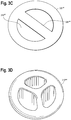
- an aperture or opening 320' within a wall of a flow unit can include one or more ribs 325"', designed to prevent a valve 310'" from being pulled into the flow unit when an over vacuum condition occurs.
- the valve 310'" is sufficiently flexible under high vacuum conditions that the valve can flex and fold when sufficient vacuum is applied.
- ribs 325"' or other similar structure(s), such as a mesh or any other alternate structure(s) ensure that the valve remains in a position within the system to limit the system volume under normal vacuum conditions, and to alter the geometry of the valve in the system under over vacuum conditions.
- the system is configured such that the valve 310"", 310'"" respectively can actually fold or bend as indicated to reduce vacuum of the system mechanically and automatically when an over vacuum condition occurs during operation.
- the valve can be designed to have physical characteristics and shape such that a portion of the valve can undergo stretching in an over vacuum condition that results in the bending or folding of the valve 310 as shown in Figure 3e .
- the aperture of the fluid unit includes three ribs that ensure the valve remains in a position within the system to limit the system volume under normal vacuum conditions, and to alter the geometry of the valve in the system under over vacuum conditions.
- a method in accordance with the principles herein, shown generally at 400 can include the step at 410 of configuring a valve that folds when subjected to over vacuum conditions in a pump system, where the valve vents automatically given a vacuum within the over vacuum condition range to decrease the vacuum in the system automatically; and at step 420, if needed, constructing a fluid flow member configuration that includes at least one component that prevents the valve from fully entering the flow unit given an over vacuum condition in a pump system.
Description
- This application claims priority to
U.S. Provisional Patent Application No. 62/210,84 filed August 27, 2015 and entitled "Lacteal Extractor Safety System and Method for Pump System." - The present disclosure relates generally to a mechanical safety system and method for a pump system.
WO2015/022244 A1 discloses a breast pump device with a safety valve. More particularly, the disclosure relates to a mechanical over-vacuum safety system and method for a vacuum pump system designed to extract milk from lactating mothers. -
-
FIG. 1 is a side view of an exemplary embodiment constructed in accordance with the principles herein; -
FIG. 1A is an side view of an exemplary mechanical safety valve system constructed in accordance with the principles herein; -
FIG. 2 is a side view, partially in section, of another exemplary embodiment constructed in accordance with the principles herein; -
FIGS. 3a-b are sectional views taken alonglines 3A ofFigure 2 with the valve in a unsealed condition and sealed condition, respectively; -
FIG. 3c is an exemplary embodiment of a portion of a fluid flow member configuration that includes at least one component that prevents the valve from fully entering the flow unit given an over vacuum condition in a pump system; -
FIGS. 3d and3e are pictures of a valve sealing the flow unit of the system under vacuum, and automatically venting under an over vacuum condition of the system, respectively. -
FIG. 4 is a flow chart of an exemplary method of constructing a lacteal extractor safety system in accordance with the principles herein. -
FIG. 5 is a front perspective view of an embodiment of a valve sealing the flow unit of the system under a vacuum and automatically venting under an over vacuum condition of the system. -
FIG. 6 is atop view of the valve illustrated inFIG. 5 . -
FIG. 7 is a side view of the valve illustrated inFIGS. 5 and 6 . -
FIG. 8 is a bottom view of the valve illustrated inFIGS. 5-7 . -
FIG. 9 is a cross-sectional view of the valve illustrated inFIGS. 5-8 taken along line 9-9 inFIG. 6 . - Throughout the various figures, like reference numbers refer to like elements of the exemplary system components. Elements can be combined in all possible combinations that can be formed to achieve exemplary systems not specifically set forth in the figures, in accordance with the principles herein. The invention, however, is defined in claim 1. Preferred embodiments of the invention are specified in the dependent claims.
-
FIG. 1 illustrates an exemplary vacuum pump system shown generally at 100, constructed in accordance with the principles herein. Thepump system 100 includes alacteal extractor 110 connectable to a lactating mother, and afluid flow member 120 through which milk extracted from the mother can flow. Thefluid flow member 120 can be formed of any length, shape, and material, and can provide or contain one or more components designed to convey milk from thelacteal extractor 110 of thepump system 100 to acollection container 130. Avacuum generating system 150 can be either directly or indirectly connected to thelacteal extractor 110. - In accordance with the principles herein, vacuum generated by the
vacuum generating system 150 and delivered to thelacteal extractor 110 can advantageously be automatically mechanically regulated to reduce the chance of an over vacuum condition in thesystem 100. To this end, one or more mechanical valves can be positioned between themilk collection container 130 and thelacteal extractor 110, where the one or more mechanical valves are designed to provide a mechanical safety valve system that is automatically actuated in response to specific vacuum ranges that can cause an over vacuum condition in the system. Although numerous pump systems employ mechanical valves to facilitate milk flow from a lacteal extractor to a container, the flow valves of conventional systems do not function as mechanical safety valves within the fluid flow path, and are not configured and tuned to mechanically open when subjected to an over vacuum condition of the system. - Alternately, in exemplary instances not forming part of the invention, the mechanical safety valve system could be positioned outside of the fluid flow path of the system, such as, for example, in the vacuum line or anywhere else in the system. In certain circumstances, the mechanical safety valve system can be positioned to serve as both a safety valve and a milk extraction valve, as illustrated according to the exemplary embodiments herein.
- In an exemplary embodiment constructed in accordance with the principles herein, a
safety valve 140A can be positioned within theflow unit 120 of thesystem 100. In yet another exemplary embodiment, asafety valve 140 B can be positioned within thecollection container 130 of thesystem 100. In still another exemplary embodiment depicted inFIG. 1A , a mechanical safety valve system of more than one safety valve, such as asafety valve 140A and asafety valve 140B, or any number of valves that form a suitable safety valve system, can be position in thesystem 100 downstream from thelacteal extractor 110 to form the mechanical safety valve system. Suitable mechanical safety valve systems constructed in accordance with the principles herein automatically and mechanically reduce vacuum in the system by altering its geometry to allow communication with atmospheric pressure under certain vacuum ranges. - Typical vacuum ranges in which an over vacuum condition can occur in the system can include, for example, from around negative 300 mmHg to about negative 350mmHg. If desired, the vacuum ranges in which an over vacuum condition can occur can be fine-tuned with feedback from a mother using the system based her comfort levels. To this end, an adjustment, mechanical, electrical or both, of vacuum ranges can be made in the system based on the feedback from the mom. Such adjustment will not affect the efficacy of the valve, but can serve to reduce the pressure at the upper limit of the over vacuum condition, rendering operation of the device more comfortable for the mom.
- In order for the mechanical safety valve system to function automatically in the system one must employ the right combination of material thickness of the valve, material properties of the valve, open or flow through diameter of the valve, and the beam or bend length of surface of the valve that achieves the safety feature in relation to the applied pressure on the valve during operation.
- As illustrated in
Figure 2 , another exemplary embodiment of a system shown generally at 200 and constructed in accordance with the principles herein can include an exemplary lacteal extractor formed of abreastshield 210, anadapter 220 connected viatubing 230 to avacuum pump 240 and acollection container 250. Aseparator unit 260 can be included to separate milk, or other fluid media, flowing from thebreastshield 210 from entering thetubing 230 or thevacuum pump 240. Anopening 270 can be provided along a bottominterior wall 280 of theadapter 220. The bottominterior wall 280 can be provided in thesystem 200 to minimize the work required by thevacuum generating system 240 to achieve desired vacuum ranges in accordance with a program or pattern of thepump system 200. Thepump system 200 can be designed so that the program or pattern is selectable by a mother. - The
system 200 can further include avalve system 290 containing a flexible,movable valve 210a. Thevalve system 290 is connectable to theadapter 220 and thecontainer 230. Known lacteal extraction systems include a flow valve to the container. Some known systems include a relief or safety valve, but not an automatic mechanical safety valve within the system. For example, a relief valve can be connected with a breastshield as discussed inU.S. Patent No. 8,070,716 to Sutrina et al . Thus, in accordance with the principles herein theexemplary valve 210a can serve, advantageously, as both a fluid flow control valve and as an automatic mechanical safety valve system within the fluid flow. - As illustrated in
Figures 3a to 3e , an exemplary mechanical safety valve system can include a flexible,movable valve 310. Thevalve 310 can control fluid flow in the system, and can allow fluid to pass into acollection container 350. Thevalve 310 can also serve as a mechanical safety valve system when the valve is constructed such that it limits the volume of the system in order to achieve upper vacuum levels, or negative pressure values, and alters the geometry of the valve to reduce vacuum levels when an over vacuum condition occurs in the system - In an exemplary embodiment shown in
Figure 3b , a valve 310' can seal an aperture 320' leading to a container in the system when vacuum is applied. In this sense, the valve 310' can function similarly to conventional lacteal extraction flow control valves. - In the exemplary embodiment shown in
Figure 3c , an aperture or opening 320' within a wall of a flow unit can include one or more ribs 325"', designed to prevent a valve 310'" from being pulled into the flow unit when an over vacuum condition occurs. In this embodiment the valve 310'" is sufficiently flexible under high vacuum conditions that the valve can flex and fold when sufficient vacuum is applied. As a result, ribs 325"' or other similar structure(s), such as a mesh or any other alternate structure(s), ensure that the valve remains in a position within the system to limit the system volume under normal vacuum conditions, and to alter the geometry of the valve in the system under over vacuum conditions. - Moreover, in the embodiment of
Figures 3d and3e , the system is configured such that thevalve 310"", 310'"" respectively can actually fold or bend as indicated to reduce vacuum of the system mechanically and automatically when an over vacuum condition occurs during operation. The valve can be designed to have physical characteristics and shape such that a portion of the valve can undergo stretching in an over vacuum condition that results in the bending or folding of thevalve 310 as shown inFigure 3e . In the exemplary embodiments ofFigures 3d and3e , the aperture of the fluid unit includes three ribs that ensure the valve remains in a position within the system to limit the system volume under normal vacuum conditions, and to alter the geometry of the valve in the system under over vacuum conditions. - Although any suitable method can be employed in accordance with a method of the present disclosure, it is contemplated that particular advantage can be achieved through the use of manufacturing methods such as, for example an exemplary method of forming a mechanical safety valve system for a pump system illustrated in
Figure 4 . A method in accordance with the principles herein, shown generally at 400 can include the step at 410 of configuring a valve that folds when subjected to over vacuum conditions in a pump system, where the valve vents automatically given a vacuum within the over vacuum condition range to decrease the vacuum in the system automatically; and atstep 420, if needed, constructing a fluid flow member configuration that includes at least one component that prevents the valve from fully entering the flow unit given an over vacuum condition in a pump system.
Claims (11)
- A pump system (100, 200, 300, 300') for lacteal extraction comprising:a mechanical safety valve (140A, 140B, 210a, 310, 310', 310'", 310"", 310"'", 310""") within a milk flow path of the system, whereinthe safety valve (140A, 140B, 210a, 310', 310'", 310"", 310'"", 310""") is configured to automatically actuate in response to specific vacuum ranges that can cause an over-vacuum condition,the pump system (100, 200, 300, 300') further comprisingan adapter (220) connected by tubing (230) to a vacuum pump (240), the adapter further connected to a collection container (130, 250, 350, 350'), wherein the mechanical safety valve (140A, 140B, 210a, 310', 310'", 310"", 310'"", 310""") is in the adapter (220),wherein the adapter (220) comprises an opening (270) on a bottom wall (280) of the adapter (220), and the mechanical safety valve (140A, 140B, 210a, 310', 310'", 310"", 310'"", 310""") is at the opening (270), andwherein the mechanical safety valve (140A, 140B, 210a, 310', 310'", 310"", 310'"", 310""") allows fluid flow by folding.
- The pump system (100, 200, 300, 300') of Claim 1, further comprising:a lacteal extractor (110, 210) connected to the adapter;wherein the mechanical safety valve (140A, 140B, 210a, 310', 310'", 310"", 310'"", 310""") is positioned between the lacteal extractor (110, 210) and the collection container (130, 250, 350, 350').
- The pump system of Claims 1 or 2, wherein the pump system (100, 200, 300, 300') includes two or more mechanical safety valves (140A, 140B, 210a, 310', 310'", 310"", 310'"", 310""") located downstream of a lacteal extractor (110, 210).
- The pump system (100, 200, 300, 300') of Claims 2 or 3, wherein the lacteal extractor (110, 210) is a breastshield (210).
- The pump system (100, 200, 300, 300') of Claim 1, wherein the opening (270) is partially covered by ribs (325"'), a mesh, or an alternate structure.
- The pump system (100, 200, 300, 300') of any of Claims 1-5 wherein the over-vacuum condition occurs between negative 300 mmHG and negative 350 mmHG.
- The pump system (100, 200, 300, 300') of any of Claims 1-6, wherein the mechanical safety valve (140A, 140B, 210a, 310', 310'", 310"", 310'"", 310""") is flexible.
- The pump system (100, 200, 300, 300') of any of Claims 1-7, wherein the mechanical safety valve (140A, 140B, 210a, 310', 310'", 310"", 310'"", 310""") undergoes stretching in an over-vacuum condition.
- The pump system of Claim 5, wherein the ribs (325'"), the mesh, or the alternate structure prevent the valve from fully traveling through the opening (270).
- The pump system of Claim 3, wherein one of the two or more mechanical valves (140B) is positioned within the collection container (130).
- The pump system (110, 200, 300, 300') of Claim 10, where the pump system (100, 200, 300, 300') comprises a lacteal extractor (110) directly or indirectly connected to a vacuum generating system (150).
Applications Claiming Priority (2)
| Application Number | Priority Date | Filing Date | Title |
|---|---|---|---|
| US201562210841P | 2015-08-27 | 2015-08-27 | |
| PCT/US2016/049183 WO2017035520A1 (en) | 2015-08-27 | 2016-08-29 | Lacteal extractor safety system and method for pump system |
Publications (2)
| Publication Number | Publication Date |
|---|---|
| EP3341040A1 EP3341040A1 (en) | 2018-07-04 |
| EP3341040B1 true EP3341040B1 (en) | 2021-07-21 |
Family
ID=56894298
Family Applications (1)
| Application Number | Title | Priority Date | Filing Date |
|---|---|---|---|
| EP16763415.3A Active EP3341040B1 (en) | 2015-08-27 | 2016-08-29 | Lacteal extractor safety system |
Country Status (7)
| Country | Link |
|---|---|
| US (1) | US20170056573A1 (en) |
| EP (1) | EP3341040B1 (en) |
| CN (1) | CN107921186B (en) |
| AU (1) | AU2016311498B2 (en) |
| CA (1) | CA2995015C (en) |
| MX (1) | MX2018002379A (en) |
| WO (1) | WO2017035520A1 (en) |
Citations (3)
| Publication number | Priority date | Publication date | Assignee | Title |
|---|---|---|---|---|
| WO2014094186A2 (en) * | 2012-12-18 | 2014-06-26 | Medela Holding Ag | Breast shield unit |
| US20140263611A1 (en) * | 2013-03-13 | 2014-09-18 | Medela Holding Ag | System and method for managing a supply of breast milk |
| CN104784766A (en) * | 2015-05-05 | 2015-07-22 | 陈俊波 | Three-way component and breast pump with three-way component |
Family Cites Families (47)
| Publication number | Priority date | Publication date | Assignee | Title |
|---|---|---|---|---|
| US3853128A (en) * | 1972-07-10 | 1974-12-10 | Deknated Inc | Valved underwater drainage apparatus |
| US3901410A (en) * | 1974-07-19 | 1975-08-26 | Robert S Schultz | Captive tip-seal valve |
| US4323067A (en) * | 1977-06-20 | 1982-04-06 | Adams Frank H | Combination breast pump and gavage feeding apparatus and method |
| US4857051A (en) * | 1980-09-05 | 1989-08-15 | Isg/Ag | Breastpump |
| US4607596A (en) * | 1983-05-11 | 1986-08-26 | Whittlestone Walter G | Milking methods and apparatus |
| CH662949A5 (en) * | 1984-03-14 | 1987-11-13 | Ameda Ag | Breast pump for sucking breast milk. |
| US4929229A (en) * | 1988-11-30 | 1990-05-29 | Isg/Ag | Breastpump having improved valve mechanism |
| US5571084A (en) * | 1994-12-12 | 1996-11-05 | Spread Spectrum Inc. | Microprocessor-controlled vested lactation system |
| US6481986B1 (en) * | 1995-08-03 | 2002-11-19 | Medela Holding Ag | Vacuum adjustment mechanism particularly adapted for a breastpump |
| EP0800836B1 (en) * | 1996-04-14 | 2003-02-26 | Medela AG | Breast pump |
| WO1999044650A1 (en) * | 1998-03-06 | 1999-09-10 | Ameda Ag Medical Equipment | Breast pump |
| US6383163B1 (en) * | 1998-05-04 | 2002-05-07 | Patricia Ann Kelly | Electric breast pump designed to simulate infant suckling |
| US6024120A (en) * | 1998-09-25 | 2000-02-15 | Sherwood Services Ag | Pressure relief valve with moving diaphragm |
| US6045529A (en) * | 1998-10-02 | 2000-04-04 | Nuesch Logistik | Drive unit for a breastpump |
| US6673036B1 (en) * | 1999-10-13 | 2004-01-06 | The First Years Inc. | Pumping breast milk |
| US6706012B2 (en) * | 2000-06-12 | 2004-03-16 | L. Jason Clute | Apparatus for expressing milk |
| JP2002336347A (en) * | 2001-05-18 | 2002-11-26 | Univ Nihon | Breast pump |
| US6663587B2 (en) * | 2001-06-22 | 2003-12-16 | Medela Holding Ag | Breastshield with multi-pressure and expansible chamber construction, related breastpump and method |
| US7727182B2 (en) * | 2002-08-23 | 2010-06-01 | Medela Holding Ag | Manual breastpump with stimulation feature |
| US6932790B2 (en) * | 2003-07-23 | 2005-08-23 | L. Jason Clute | Adapter for human breast pumps |
| US8137305B2 (en) * | 2007-01-22 | 2012-03-20 | Kelly Patricia A | Programmable electric breast pump |
| CN2647322Y (en) * | 2003-09-04 | 2004-10-13 | 张海涛 | Breast pump with massage function |
| RU2392975C2 (en) * | 2004-09-20 | 2010-06-27 | Медела Холдинг Аг | Air-valve membrane pump |
| JP4657345B2 (en) * | 2005-04-07 | 2011-03-23 | メデラ ホールディング アーゲー | Valves, especially valves for breast cap sets |
| WO2008123744A1 (en) * | 2007-04-10 | 2008-10-16 | Agabang & Company | Baby bottle |
| US8070716B2 (en) * | 2007-04-11 | 2011-12-06 | Medela Holding Ag | Method and apparatus for minimum negative pressure control, particularly for a breastpump with breastshield pressure control system |
| US8070715B2 (en) * | 2007-04-11 | 2011-12-06 | Medela Holding Ag | Method and apparatus for minimum negative pressure control, particularly for breastpump with breastshield pressure control system |
| US8109901B2 (en) * | 2008-11-07 | 2012-02-07 | Simplisse, Inc. | Breast pump |
| US8545438B2 (en) * | 2009-06-22 | 2013-10-01 | Lansinoh Laboratories, Inc. | Breast pump |
| CH705295A1 (en) * | 2011-07-18 | 2013-01-31 | Medela Holding Ag | Breastshield unit. |
| JP5918970B2 (en) * | 2011-11-02 | 2016-05-18 | 株式会社テクノ高槻 | Electromagnetic vibration type diaphragm pump |
| ES2493073T3 (en) * | 2011-12-21 | 2014-09-11 | Mapa Gmbh | Electric breast pump |
| US8961454B2 (en) * | 2012-07-24 | 2015-02-24 | Chean-Shui Chen | Milk expressing device capable of simulating a baby's suckling |
| US8702646B2 (en) * | 2012-08-14 | 2014-04-22 | Dan Garbez | Submersible valve for a breast milk collection device with self contained reservoir |
| EP2838578B1 (en) * | 2012-09-07 | 2015-10-07 | Koninklijke Philips N.V. | A breast pump system |
| JP6065484B2 (en) * | 2012-09-19 | 2017-01-25 | ジェクス株式会社 | Breastfeeding check valve |
| WO2014045169A1 (en) * | 2012-09-24 | 2014-03-27 | Koninklijke Philips N.V. | A breast pump system |
| CH707124A1 (en) * | 2012-10-25 | 2014-04-30 | Medela Holding Ag | Breastshield unit with media separator. |
| US9907889B2 (en) * | 2013-01-16 | 2018-03-06 | Kci Licensing, Inc. | Manually-actuated reduced pressure treatment system with audible leak indicator |
| EP2968713B1 (en) * | 2013-03-14 | 2019-10-02 | Medela Holding AG | Small-volume collection for a breastpump system |
| CH707857A1 (en) * | 2013-04-02 | 2014-10-15 | Medela Holding Ag | Device with a flow channel. |
| US20160199552A1 (en) * | 2013-08-12 | 2016-07-14 | Koninklijke Philips N.V. | Safety valve |
| US9435450B2 (en) * | 2014-02-04 | 2016-09-06 | Terumo Cardiovascular Systems, Inc. | Pressure differential relief valve |
| WO2016014483A1 (en) * | 2014-07-22 | 2016-01-28 | Exploramed Nc7, Llc | Breast pump system and methods |
| WO2016044802A1 (en) * | 2014-09-19 | 2016-03-24 | Naya Health, Inc. | Quantification and inventory management of expressed human breast milk |
| EP3239568B1 (en) * | 2014-12-26 | 2019-04-10 | Murata Manufacturing Co., Ltd. | Valve and fluid control device |
| US20180093024A1 (en) * | 2016-10-05 | 2018-04-05 | Moxxly, Inc. | Breast pump milk capture and collection system |
-
2016
- 2016-08-29 US US15/249,768 patent/US20170056573A1/en not_active Abandoned
- 2016-08-29 EP EP16763415.3A patent/EP3341040B1/en active Active
- 2016-08-29 WO PCT/US2016/049183 patent/WO2017035520A1/en active Application Filing
- 2016-08-29 AU AU2016311498A patent/AU2016311498B2/en active Active
- 2016-08-29 MX MX2018002379A patent/MX2018002379A/en unknown
- 2016-08-29 CN CN201680048948.1A patent/CN107921186B/en active Active
- 2016-08-29 CA CA2995015A patent/CA2995015C/en active Active
Patent Citations (3)
| Publication number | Priority date | Publication date | Assignee | Title |
|---|---|---|---|---|
| WO2014094186A2 (en) * | 2012-12-18 | 2014-06-26 | Medela Holding Ag | Breast shield unit |
| US20140263611A1 (en) * | 2013-03-13 | 2014-09-18 | Medela Holding Ag | System and method for managing a supply of breast milk |
| CN104784766A (en) * | 2015-05-05 | 2015-07-22 | 陈俊波 | Three-way component and breast pump with three-way component |
Also Published As
| Publication number | Publication date |
|---|---|
| CA2995015C (en) | 2023-03-14 |
| AU2016311498A1 (en) | 2018-02-22 |
| AU2016311498B2 (en) | 2020-10-08 |
| EP3341040A1 (en) | 2018-07-04 |
| CN107921186A (en) | 2018-04-17 |
| MX2018002379A (en) | 2018-04-11 |
| US20170056573A1 (en) | 2017-03-02 |
| WO2017035520A1 (en) | 2017-03-02 |
| CA2995015A1 (en) | 2017-03-02 |
| CN107921186B (en) | 2022-02-18 |
Similar Documents
| Publication | Publication Date | Title |
|---|---|---|
| US10137291B2 (en) | Valved connector for medical lines | |
| CN106456958B (en) | Valved conduit apparatus and related methods | |
| EP2968713B1 (en) | Small-volume collection for a breastpump system | |
| EP3125966B1 (en) | Breast pump and expression kit for a breast pump | |
| EP3169621B1 (en) | Outlet for a urostomy appliance | |
| CN105050653B (en) | Anury formula needless valve system | |
| CN110898269A (en) | Manual breast pump and method of use | |
| WO2018051256A3 (en) | A method and a receptacle bag for emptying a urinary bag | |
| EP2890421B1 (en) | Spring-open sheeting for fluid processing cassette | |
| EP3341040B1 (en) | Lacteal extractor safety system | |
| US10155654B2 (en) | Vessel overfill protection system | |
| EP3156703A1 (en) | Check valve dual-orifice chamfered housing | |
| CN109219455B (en) | Dialysis apparatus and constant-current restrictor | |
| EP3144506B1 (en) | Fluid metering valve | |
| US11446415B2 (en) | Fluid control device | |
| US11167072B2 (en) | Suction discharge unit and suction discharge device | |
| EP3590572A1 (en) | Valve for bypass conduit | |
| CN105979980B (en) | The hose group of the medicine of the fluid cartridge of medicine and the fluid cartridge with medicine | |
| CN107427615B (en) | Medium separation device | |
| CN103533494B (en) | The pump and application method of audiphone | |
| WO2017120015A1 (en) | Device to enable infants with cleft palate to breast feed | |
| JP6419481B2 (en) | Structure for fixing diaphragm to drive shaft, method for fixing diaphragm to drive shaft, and electromagnetic control valve | |
| EP3818581A1 (en) | Refuelling unit for refuelling fuel cell of hearing aid | |
| EP2847503B1 (en) | Assembly comprising a connector and a safety valve device | |
| JP2016035283A (en) | Diaphragm manufacturing method and diaphragm |
Legal Events
| Date | Code | Title | Description |
|---|---|---|---|
| STAA | Information on the status of an ep patent application or granted ep patent |
Free format text: STATUS: THE INTERNATIONAL PUBLICATION HAS BEEN MADE |
|
| PUAI | Public reference made under article 153(3) epc to a published international application that has entered the european phase |
Free format text: ORIGINAL CODE: 0009012 |
|
| STAA | Information on the status of an ep patent application or granted ep patent |
Free format text: STATUS: REQUEST FOR EXAMINATION WAS MADE |
|
| 17P | Request for examination filed |
Effective date: 20180208 |
|
| AK | Designated contracting states |
Kind code of ref document: A1 Designated state(s): AL AT BE BG CH CY CZ DE DK EE ES FI FR GB GR HR HU IE IS IT LI LT LU LV MC MK MT NL NO PL PT RO RS SE SI SK SM TR |
|
| AX | Request for extension of the european patent |
Extension state: BA ME |
|
| RIN1 | Information on inventor provided before grant (corrected) |
Inventor name: HOLTZ, RAYMOND |
|
| DAV | Request for validation of the european patent (deleted) | ||
| DAX | Request for extension of the european patent (deleted) | ||
| STAA | Information on the status of an ep patent application or granted ep patent |
Free format text: STATUS: EXAMINATION IS IN PROGRESS |
|
| 17Q | First examination report despatched |
Effective date: 20200212 |
|
| STAA | Information on the status of an ep patent application or granted ep patent |
Free format text: STATUS: EXAMINATION IS IN PROGRESS |
|
| GRAP | Despatch of communication of intention to grant a patent |
Free format text: ORIGINAL CODE: EPIDOSNIGR1 |
|
| STAA | Information on the status of an ep patent application or granted ep patent |
Free format text: STATUS: GRANT OF PATENT IS INTENDED |
|
| INTG | Intention to grant announced |
Effective date: 20210217 |
|
| RIN1 | Information on inventor provided before grant (corrected) |
Inventor name: HOLTZ, RAYMOND |
|
| GRAS | Grant fee paid |
Free format text: ORIGINAL CODE: EPIDOSNIGR3 |
|
| GRAA | (expected) grant |
Free format text: ORIGINAL CODE: 0009210 |
|
| STAA | Information on the status of an ep patent application or granted ep patent |
Free format text: STATUS: THE PATENT HAS BEEN GRANTED |
|
| AK | Designated contracting states |
Kind code of ref document: B1 Designated state(s): AL AT BE BG CH CY CZ DE DK EE ES FI FR GB GR HR HU IE IS IT LI LT LU LV MC MK MT NL NO PL PT RO RS SE SI SK SM TR |
|
| REG | Reference to a national code |
Ref country code: GB Ref legal event code: FG4D |
|
| REG | Reference to a national code |
Ref country code: CH Ref legal event code: EP |
|
| REG | Reference to a national code |
Ref country code: DE Ref legal event code: R096 Ref document number: 602016060932 Country of ref document: DE |
|
| REG | Reference to a national code |
Ref country code: AT Ref legal event code: REF Ref document number: 1411998 Country of ref document: AT Kind code of ref document: T Effective date: 20210815 |
|
| REG | Reference to a national code |
Ref country code: IE Ref legal event code: FG4D |
|
| REG | Reference to a national code |
Ref country code: NL Ref legal event code: FP |
|
| REG | Reference to a national code |
Ref country code: LT Ref legal event code: MG9D |
|
| REG | Reference to a national code |
Ref country code: AT Ref legal event code: MK05 Ref document number: 1411998 Country of ref document: AT Kind code of ref document: T Effective date: 20210721 |
|
| PG25 | Lapsed in a contracting state [announced via postgrant information from national office to epo] |
Ref country code: AT Free format text: LAPSE BECAUSE OF FAILURE TO SUBMIT A TRANSLATION OF THE DESCRIPTION OR TO PAY THE FEE WITHIN THE PRESCRIBED TIME-LIMIT Effective date: 20210721 Ref country code: BG Free format text: LAPSE BECAUSE OF FAILURE TO SUBMIT A TRANSLATION OF THE DESCRIPTION OR TO PAY THE FEE WITHIN THE PRESCRIBED TIME-LIMIT Effective date: 20211021 Ref country code: LT Free format text: LAPSE BECAUSE OF FAILURE TO SUBMIT A TRANSLATION OF THE DESCRIPTION OR TO PAY THE FEE WITHIN THE PRESCRIBED TIME-LIMIT Effective date: 20210721 Ref country code: ES Free format text: LAPSE BECAUSE OF FAILURE TO SUBMIT A TRANSLATION OF THE DESCRIPTION OR TO PAY THE FEE WITHIN THE PRESCRIBED TIME-LIMIT Effective date: 20210721 Ref country code: FI Free format text: LAPSE BECAUSE OF FAILURE TO SUBMIT A TRANSLATION OF THE DESCRIPTION OR TO PAY THE FEE WITHIN THE PRESCRIBED TIME-LIMIT Effective date: 20210721 Ref country code: HR Free format text: LAPSE BECAUSE OF FAILURE TO SUBMIT A TRANSLATION OF THE DESCRIPTION OR TO PAY THE FEE WITHIN THE PRESCRIBED TIME-LIMIT Effective date: 20210721 Ref country code: NO Free format text: LAPSE BECAUSE OF FAILURE TO SUBMIT A TRANSLATION OF THE DESCRIPTION OR TO PAY THE FEE WITHIN THE PRESCRIBED TIME-LIMIT Effective date: 20211021 Ref country code: PT Free format text: LAPSE BECAUSE OF FAILURE TO SUBMIT A TRANSLATION OF THE DESCRIPTION OR TO PAY THE FEE WITHIN THE PRESCRIBED TIME-LIMIT Effective date: 20211122 Ref country code: SE Free format text: LAPSE BECAUSE OF FAILURE TO SUBMIT A TRANSLATION OF THE DESCRIPTION OR TO PAY THE FEE WITHIN THE PRESCRIBED TIME-LIMIT Effective date: 20210721 Ref country code: RS Free format text: LAPSE BECAUSE OF FAILURE TO SUBMIT A TRANSLATION OF THE DESCRIPTION OR TO PAY THE FEE WITHIN THE PRESCRIBED TIME-LIMIT Effective date: 20210721 |
|
| PG25 | Lapsed in a contracting state [announced via postgrant information from national office to epo] |
Ref country code: PL Free format text: LAPSE BECAUSE OF FAILURE TO SUBMIT A TRANSLATION OF THE DESCRIPTION OR TO PAY THE FEE WITHIN THE PRESCRIBED TIME-LIMIT Effective date: 20210721 Ref country code: LV Free format text: LAPSE BECAUSE OF FAILURE TO SUBMIT A TRANSLATION OF THE DESCRIPTION OR TO PAY THE FEE WITHIN THE PRESCRIBED TIME-LIMIT Effective date: 20210721 Ref country code: GR Free format text: LAPSE BECAUSE OF FAILURE TO SUBMIT A TRANSLATION OF THE DESCRIPTION OR TO PAY THE FEE WITHIN THE PRESCRIBED TIME-LIMIT Effective date: 20211022 |
|
| REG | Reference to a national code |
Ref country code: DE Ref legal event code: R097 Ref document number: 602016060932 Country of ref document: DE |
|
| PG25 | Lapsed in a contracting state [announced via postgrant information from national office to epo] |
Ref country code: DK Free format text: LAPSE BECAUSE OF FAILURE TO SUBMIT A TRANSLATION OF THE DESCRIPTION OR TO PAY THE FEE WITHIN THE PRESCRIBED TIME-LIMIT Effective date: 20210721 |
|
| PLBE | No opposition filed within time limit |
Free format text: ORIGINAL CODE: 0009261 |
|
| STAA | Information on the status of an ep patent application or granted ep patent |
Free format text: STATUS: NO OPPOSITION FILED WITHIN TIME LIMIT |
|
| PG25 | Lapsed in a contracting state [announced via postgrant information from national office to epo] |
Ref country code: SM Free format text: LAPSE BECAUSE OF FAILURE TO SUBMIT A TRANSLATION OF THE DESCRIPTION OR TO PAY THE FEE WITHIN THE PRESCRIBED TIME-LIMIT Effective date: 20210721 Ref country code: SK Free format text: LAPSE BECAUSE OF FAILURE TO SUBMIT A TRANSLATION OF THE DESCRIPTION OR TO PAY THE FEE WITHIN THE PRESCRIBED TIME-LIMIT Effective date: 20210721 Ref country code: RO Free format text: LAPSE BECAUSE OF FAILURE TO SUBMIT A TRANSLATION OF THE DESCRIPTION OR TO PAY THE FEE WITHIN THE PRESCRIBED TIME-LIMIT Effective date: 20210721 Ref country code: MC Free format text: LAPSE BECAUSE OF FAILURE TO SUBMIT A TRANSLATION OF THE DESCRIPTION OR TO PAY THE FEE WITHIN THE PRESCRIBED TIME-LIMIT Effective date: 20210721 Ref country code: EE Free format text: LAPSE BECAUSE OF FAILURE TO SUBMIT A TRANSLATION OF THE DESCRIPTION OR TO PAY THE FEE WITHIN THE PRESCRIBED TIME-LIMIT Effective date: 20210721 Ref country code: CZ Free format text: LAPSE BECAUSE OF FAILURE TO SUBMIT A TRANSLATION OF THE DESCRIPTION OR TO PAY THE FEE WITHIN THE PRESCRIBED TIME-LIMIT Effective date: 20210721 Ref country code: AL Free format text: LAPSE BECAUSE OF FAILURE TO SUBMIT A TRANSLATION OF THE DESCRIPTION OR TO PAY THE FEE WITHIN THE PRESCRIBED TIME-LIMIT Effective date: 20210721 Ref country code: LU Free format text: LAPSE BECAUSE OF NON-PAYMENT OF DUE FEES Effective date: 20210829 |
|
| 26N | No opposition filed |
Effective date: 20220422 |
|
| PG25 | Lapsed in a contracting state [announced via postgrant information from national office to epo] |
Ref country code: IT Free format text: LAPSE BECAUSE OF FAILURE TO SUBMIT A TRANSLATION OF THE DESCRIPTION OR TO PAY THE FEE WITHIN THE PRESCRIBED TIME-LIMIT Effective date: 20210721 Ref country code: IE Free format text: LAPSE BECAUSE OF NON-PAYMENT OF DUE FEES Effective date: 20210829 |
|
| PG25 | Lapsed in a contracting state [announced via postgrant information from national office to epo] |
Ref country code: HU Free format text: LAPSE BECAUSE OF FAILURE TO SUBMIT A TRANSLATION OF THE DESCRIPTION OR TO PAY THE FEE WITHIN THE PRESCRIBED TIME-LIMIT; INVALID AB INITIO Effective date: 20160829 |
|
| P01 | Opt-out of the competence of the unified patent court (upc) registered |
Effective date: 20230524 |
|
| PG25 | Lapsed in a contracting state [announced via postgrant information from national office to epo] |
Ref country code: CY Free format text: LAPSE BECAUSE OF FAILURE TO SUBMIT A TRANSLATION OF THE DESCRIPTION OR TO PAY THE FEE WITHIN THE PRESCRIBED TIME-LIMIT Effective date: 20210721 |
|
| PGFP | Annual fee paid to national office [announced via postgrant information from national office to epo] |
Ref country code: NL Payment date: 20230719 Year of fee payment: 8 |
|
| PGFP | Annual fee paid to national office [announced via postgrant information from national office to epo] |
Ref country code: GB Payment date: 20230706 Year of fee payment: 8 Ref country code: CH Payment date: 20230902 Year of fee payment: 8 |
|
| PGFP | Annual fee paid to national office [announced via postgrant information from national office to epo] |
Ref country code: FR Payment date: 20230710 Year of fee payment: 8 Ref country code: DE Payment date: 20230712 Year of fee payment: 8 Ref country code: BE Payment date: 20230719 Year of fee payment: 8 |