EP3340720A1 - Method and apparatus for transmitting data in wireless communication system supporting carrier aggregation - Google Patents
Method and apparatus for transmitting data in wireless communication system supporting carrier aggregation Download PDFInfo
- Publication number
- EP3340720A1 EP3340720A1 EP16866612.1A EP16866612A EP3340720A1 EP 3340720 A1 EP3340720 A1 EP 3340720A1 EP 16866612 A EP16866612 A EP 16866612A EP 3340720 A1 EP3340720 A1 EP 3340720A1
- Authority
- EP
- European Patent Office
- Prior art keywords
- base station
- data
- rlc
- assigned
- sequence numbers
- Prior art date
- Legal status (The legal status is an assumption and is not a legal conclusion. Google has not performed a legal analysis and makes no representation as to the accuracy of the status listed.)
- Granted
Links
- 238000000034 method Methods 0.000 title claims abstract description 62
- 230000002776 aggregation Effects 0.000 title claims abstract description 26
- 238000004220 aggregation Methods 0.000 title claims abstract description 26
- 238000004891 communication Methods 0.000 title claims abstract description 25
- 230000005540 biological transmission Effects 0.000 claims abstract description 20
- 238000012545 processing Methods 0.000 claims description 37
- 230000008569 process Effects 0.000 claims description 15
- 238000013468 resource allocation Methods 0.000 claims description 13
- 238000012546 transfer Methods 0.000 claims description 5
- 101000741965 Homo sapiens Inactive tyrosine-protein kinase PRAG1 Proteins 0.000 description 26
- 102100038659 Inactive tyrosine-protein kinase PRAG1 Human genes 0.000 description 26
- 238000010586 diagram Methods 0.000 description 18
- 238000005516 engineering process Methods 0.000 description 6
- 239000000969 carrier Substances 0.000 description 5
- 238000010295 mobile communication Methods 0.000 description 3
- 230000004048 modification Effects 0.000 description 3
- 238000012986 modification Methods 0.000 description 3
- 230000007423 decrease Effects 0.000 description 2
- 230000009977 dual effect Effects 0.000 description 2
- 238000007726 management method Methods 0.000 description 2
- 238000012384 transportation and delivery Methods 0.000 description 2
- 239000002699 waste material Substances 0.000 description 2
- 230000006978 adaptation Effects 0.000 description 1
- 230000003044 adaptive effect Effects 0.000 description 1
- 230000004075 alteration Effects 0.000 description 1
- 230000015556 catabolic process Effects 0.000 description 1
- 230000006835 compression Effects 0.000 description 1
- 238000007906 compression Methods 0.000 description 1
- 230000006837 decompression Effects 0.000 description 1
- 238000006731 degradation reaction Methods 0.000 description 1
- 230000000694 effects Effects 0.000 description 1
- 230000007774 longterm Effects 0.000 description 1
- 230000011218 segmentation Effects 0.000 description 1
- 230000011664 signaling Effects 0.000 description 1
- 239000013589 supplement Substances 0.000 description 1
Images


Classifications
-
- H—ELECTRICITY
- H04—ELECTRIC COMMUNICATION TECHNIQUE
- H04W—WIRELESS COMMUNICATION NETWORKS
- H04W72/00—Local resource management
- H04W72/12—Wireless traffic scheduling
-
- H—ELECTRICITY
- H04—ELECTRIC COMMUNICATION TECHNIQUE
- H04L—TRANSMISSION OF DIGITAL INFORMATION, e.g. TELEGRAPHIC COMMUNICATION
- H04L1/00—Arrangements for detecting or preventing errors in the information received
- H04L1/12—Arrangements for detecting or preventing errors in the information received by using return channel
- H04L1/16—Arrangements for detecting or preventing errors in the information received by using return channel in which the return channel carries supervisory signals, e.g. repetition request signals
- H04L1/18—Automatic repetition systems, e.g. Van Duuren systems
- H04L1/1829—Arrangements specially adapted for the receiver end
- H04L1/1854—Scheduling and prioritising arrangements
-
- H—ELECTRICITY
- H04—ELECTRIC COMMUNICATION TECHNIQUE
- H04L—TRANSMISSION OF DIGITAL INFORMATION, e.g. TELEGRAPHIC COMMUNICATION
- H04L5/00—Arrangements affording multiple use of the transmission path
- H04L5/0001—Arrangements for dividing the transmission path
- H04L5/0003—Two-dimensional division
- H04L5/0005—Time-frequency
- H04L5/0007—Time-frequency the frequencies being orthogonal, e.g. OFDM(A), DMT
- H04L5/001—Time-frequency the frequencies being orthogonal, e.g. OFDM(A), DMT the frequencies being arranged in component carriers
-
- H—ELECTRICITY
- H04—ELECTRIC COMMUNICATION TECHNIQUE
- H04W—WIRELESS COMMUNICATION NETWORKS
- H04W72/00—Local resource management
- H04W72/04—Wireless resource allocation
- H04W72/044—Wireless resource allocation based on the type of the allocated resource
- H04W72/0446—Resources in time domain, e.g. slots or frames
-
- H—ELECTRICITY
- H04—ELECTRIC COMMUNICATION TECHNIQUE
- H04W—WIRELESS COMMUNICATION NETWORKS
- H04W88/00—Devices specially adapted for wireless communication networks, e.g. terminals, base stations or access point devices
- H04W88/08—Access point devices
-
- H—ELECTRICITY
- H04—ELECTRIC COMMUNICATION TECHNIQUE
- H04L—TRANSMISSION OF DIGITAL INFORMATION, e.g. TELEGRAPHIC COMMUNICATION
- H04L1/00—Arrangements for detecting or preventing errors in the information received
- H04L2001/0092—Error control systems characterised by the topology of the transmission link
- H04L2001/0097—Relays
Definitions
- the present invention relates to a wireless communication system supporting carrier aggregation and, in particular, to a method and apparats for transmitting data to a terminal over multiple carriers.
- the mobile communication system has been developed for the user to communicate on the move. With the rapid advance of technologies, the mobile communication system has evolved to the level capable of providing high speed data communication services as well as a voice telephony service.
- LTE long-term evolution
- 3GPP 3 rd generation partnership project
- Carrier Aggregation is a technology allowing a terminal to use multiple downlink carriers and multiple uplink carriers.
- inter-base station latencies may cause data transmission resource waste.
- the present invention has been conceived to solve at least part of the above problem and aims to provide a method and apparatus for distributing, in advance, data and sequence numbers for the corresponding data to protect against data transmission resource waste caused by latencies among the base stations that transmit the data over aggregated frequency resources.
- a data transmission method of a base station in a wireless communication system supporting carrier aggregation includes identifying whether a condition for assigning data to be transmitted is fulfilled; determining, if the condition is fulfilled, radio link control (RLC) data to be assigned to the base station and any other base station and sequence numbers associated with the RLC data; and transferring the RLC data and sequence numbers assigned to the any other base station.
- RLC radio link control
- a data transmission method of a base station in a wireless communication system supporting carrier aggregation includes receiving, if a condition for assigning data to be transmitted is fulfilled, radio link control (RLC) data assigned to the base station and sequence numbers associated with the RLC data from any other base station; and performing terminal scheduling based on the received RLC data and sequence numbers.
- RLC radio link control
- a base station of a wireless communication system supporting carrier aggregation includes a communication unit configured to transmit and receive signals and a controller configured to control to identify whether a condition for assigning data to be transmitted is fulfilled; determine, if the condition is fulfilled, radio link control (RLC) data to be assigned to the base station and any other base station and sequence numbers associated with the RLC data; and transfer the RLC data and sequence numbers assigned to the any other base station.
- RLC radio link control
- a base station of a wireless communication system supporting carrier aggregation includes a communication unit configured to transmit and receive signals and a controller configured to control to receive, if a condition for assigning data to be transmitted is fulfilled, radio link control (RLC) data assigned to the base station and sequence numbers associated with the RLC data from any other base station and perform terminal scheduling based on the received RLC data and sequence numbers.
- RLC radio link control
- the present invention is advantageous in terms of improving network resource utilization efficiency, when multiple base stations transmit data over aggregated frequency resources, by assigning data and sequence numbers for the corresponding data among the base stations.
- the description is directed to the advanced E-UTRA (or LTE-A) supporting carrier aggregation, it will be understood by those skilled in the art that the subject matter of the present invention can be applied also to other communication systems having a similar technical background and channel format, with a slight modification, without departing from the spirit and scope of the present invention.
- the subject matter of the present invention is applicable to the multicarrier HSPA supporting carrier aggregation.
- Various embodiments of the present invention relate to method and apparatuses for carrier aggregation (CA) among multiple base stations and are directed to downlink data transmission in a wireless communication system.
- CA carrier aggregation
- CA may include all the types of frequency resource aggregation techniques including Rel-12 dual connectivity (DC), Rel-12 TDD-FDD CA, Rel-13 licensed assisted access (LAA), TDD-FDD dual connectivity, LTE-U supplement downlink (SDL), LTE-U CA, LTE-WLAN aggregation, and LTE-Wi-Fi aggregation, as well as Rel-10 CA of 3GPP LTE standard.
- DC Rel-12 dual connectivity
- LAA licensed assisted access
- TDD-FDD dual connectivity LTE-U supplement downlink (SDL)
- LTE-U CA LTE-WLAN aggregation
- LTE-Wi-Fi aggregation LTE-Wi-Fi aggregation
- FIG. 1 is a schematic diagram illustrating architecture of an LTE system.
- the radio access network of the LTE system includes evolved node Bs (hereinafter, interchangeably referred to as eNB, node B, and base station) 105, 110, 115, and 120, a mobility management entity (MME) 125, and a serving-gateway (S-GW) 130.
- the user equipment (hereinafter, interchangeably referred to as UE and terminal) 135 connects to an external network via the eNBs 105, 110, 115, and 120 and the S-GW 130.
- the eNBs 105, 110, 115, and 120 correspond to legacy node Bs of a UMTS system.
- the UE 135 connects to eNBs 105, 110, 115, and 120 through a radio channel, and the eNBs 105, 110, 115, and 120 have functions more complex than those of the legacy node B.
- VoIP Voice over IP
- one eNB operates multiple cells.
- the LTE system adopts orthogonal frequency division multiplexing (OFDM) as a radio access technology to secure a data rate of up to 100 Mbps in a bandwidth of 20 MHz.
- the LTE system also adopts Adaptive Modulation and Coding (AMC) to determine the modulation scheme and channel coding rate in adaptation to the channel condition of the UE.
- OFDM orthogonal frequency division multiplexing
- AMC Adaptive Modulation and Coding
- the S-GW 130 handles data bearer functions to establish and release data bearers under the control of the MME 125.
- the MME 125 handles various control functions as well as the mobile management function and has connections with the eNBs.
- FIG. 2 is a diagram illustrating a protocol stack for use in a LTE system.
- the protocol stack of the interface between the UE and the eNB in the LTE system includes a physical layer denoted by reference numbers 220 and 225, medium access control (MAC) layer denoted by reference numbers 215 and 230, radio link control (RLC) layer denoted by reference numbers 210 and 235, and packet data convergence control (PDCP) layer denoted by reference numbers 205 and 240.
- MAC medium access control
- RLC radio link control
- PDCP packet data convergence control
- the PDCP layer denoted by reference numbers 205 and 240 takes charge of compressing/decompressing an IP header.
- the RLC layer denoted by reference numbers 210 and 235 takes charge of reformatting PDCP packet data units (PDUs) for ARQ operation.
- PDUs packet data units
- the MAC layer denoted by reference number 215 and 230 allows for connection of multiple RLC entities established for one UE and takes charge of multiplexing RLC PDUs from the RLC layer into a MAC PDU and demultiplexing a MAC PDU into RLC PDUs.
- the PHY layer denoted by reference numbers 220 and 225 takes charge of channel-coding and modulation on higher layer data to generate and transmit OFDM symbols over a radio channel and demodulating and channel-decoding on OFDM symbols received over the radio channel to deliver the decoded data to the higher layers.
- the UE may have frequency specific-cells including a primary cell (PCell), which uniquely allows for an RRC connection, and other cells called secondary cells (SCells).
- PCell primary cell
- SCells secondary cells
- multi-frequency characteristics are observed at the MAC/PHY/RF layer but are transparent to the higher layers above the MAC layer in view of the downlink (DL) layer-2 structure. That is, the PDCP and RLC layer entities are established regardless of the number of carriers, while as many of the MAC/PHY/RF layer entities are established as the number of carriers.
- the Rel-10 CA technique is applied to different eNBs (e.g., PCell and SCells are hosted by different eNBs), it may be assumed that the individual eNBs use the RLC located at the eNB hosting the PCell.
- the MAC/PHY entities associated with the RLC entity are located at different eNBs, there is a need of signal exchange between the eNB hosting the PCell and the eNBs hosting the SCells according to the RLC/MAC/PHY processing procedure.
- the present invention proposes a method for utilizing network resources efficiently through inter-eNB frequency resource aggregation, and this is explained in various embodiments.
- the methods and apparatus explained in the various embodiments of the present invention may be applied for utilizing SCell resources efficiently in the Rel-10 CA-based inter-eNB frequency resource aggregation and other inter-eNB frequency resource aggregation techniques including Rel-12 DC-based inter-eNB frequency resource aggregation.
- an eNB has a virtual RLC to support inter-eNB frequency aggregation.
- An embodiment of the present invention is directed to an algorithm for assigning data to different eNBs in advance to support inter-eNB carrier aggregation.
- the terms “primary eNB” and “secondary eNB” are used; the term “eNB” denotes a device that communicates with UEs and controls the operations of the UEs, and it may be assumed that the first eNB establishes an RRC connection. That is, an eNB hosting a PCell is referred to as a primary eNB, and an eNB hosting an SCell is referred to as secondary eNB. There exists only one primary eNB per bearer and one or more secondary eNBs. It is not essential for an eNB to host only one cell, i.e., the eNB may host multiple cells with respective frequencies.
- the present invention is applicable to all the types of frequency resource aggregation techniques, e.g., Rel-10 CA by substituting the terms “PCell” and “SCell” for the terms “primary eNB” and “secondary eNB,” respectively, and Rel-12 DC by substituting the terms “MeNB” and “SeNB” for the terms “primary eNB” and “secondary eNB,” respectively.
- the SCell downlink data may be stored in a virtual RLC entity located in the secondary eNB, in advance, according to a data pre-assignment algorithm.
- the MAC PDUs carrying the SCell downlink data may be generated by the virtual RLC. This may allow the inter-eNB latency caused by delivery of SCell resource allocation result, RLC sequence number (SN), and MAC PDUs to be cancelled.
- the ACK/NACK that is transmitted only through the PCell should be transferred from the PCell to the SCell.
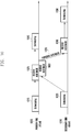
- FIG. 3 is a conceptual diagram illustrating an inter-eNB frequency resource allocation procedure according to an embodiment of the present invention.
- the primary eNB 310 and the secondary eNB 315 are connected to each other through a wireless or wired network 320 to exchange signals.
- the S-GW 305 establishes a data bearer with the primary eNB 310 hosting the PCell.
- the RLC of the primary eNB 310 assigns downlink RLC data to the primary and secondary eNBs 310 and 320 along with RLC SNs as denoted by reference number 325.
- the RLC entity of the primary eNB 310 sends the RLC data and corresponding RLC SNs assigned to the secondary eNB 315 to the virtual RLC of the secondary eNB 315.
- the RLC of the primary eNB 310 sends ACK/NACK corresponding to the SCell downlink data to the virtual RLC 335.
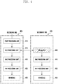
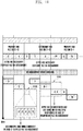
- FIG. 4 is a diagram illustrating schematic configurations of a primary eNB and a secondary eNB according to an embodiment of the present invention.
- Each of the primary and secondary eNBs 405 and 435 may include a communication unit for communicating signals and a controller for controlling the communication unit and overall operations to implement the present invention.
- the communication unit may include an RF module 430 or 455.
- the controller may include at least one of a PDCP processing unit 410, an RLC processing unit 415, a virtual RLC processing unit 440, a MAC processing unit 420 or 445, and a PHY processing unit 425 or 450.
- the eNBs are not limited to the depicted configuration, and they may be implemented in various configurations.
- the primary eNB 405 may include a PDCP processing unit 410, an RLC processing unit 415, a MAC processing unit 420, a PHY processing unit 425, and an RF module 430.
- the PDCP processing unit 410 is responsible for IP header compression/ decompression.
- the RLC processing unit 415 is responsible for reformatting PDCP PDUs for ARQ operation. According to an embodiment of the present invention, the RLC processing unit 415 may be responsible for a data pre-assignment function for assigning data, in advance, to eNBs in CA mode.
- the RLC processing unit 415 may collect and manage information for use in determining whether to perform the data pre-assignment.
- the RLC processing unit 415 may determine to perform the data pre-assignment based on the information and assign data to the eNBs based on the determination result.
- the RLC processing unit 415 may send the corresponding eNBs the data along with corresponding RLC SNs.
- the RLC processing unit 415 of the primary eNB 405 may perform the data pre-assignment per radio bearer periodically when there are data to be transmitted to the UE.
- the data pre-assignment may be performed by the PDCP processing unit 410.
- the information for use in determining whether to perform the data pre-assignment may include at least one of eNB-specific buffer occupancy (BO) size (BOn denotes BO of the n th eNB), latency (dn denotes latency between the first eNB and the n th eNB), and data rate (Tn denotes the data rate from the n th eNB to the UE).
- BOn eNB-specific buffer occupancy
- dn denotes latency between the first eNB and the n th eNB
- data rate denotes the data rate from the n th eNB to the UE.
- n may indicate one of a primary, a first secondary, a second secondary, ..., and N th secondary eNBs.
- the RLC processing unit 415 may determine whether a data pre-assignment condition is satisfied per eNB.
- BOn, dn, and Tn are used as shown in formula (1).
- the primary eNB determines the data size (Sn) to be pre-assigned to the eNB and a number of RLC SNs (Rn) to be assigned to the eNB based on BOn, dn, and Tn as shown in formula (2).
- S 1 , R 1 , ... , S n , R n g B O 1 , d 1 , T 1 , ... , B O n , d n , T n
- the size of data and the number of SNs to be assigned to an eNB may increase as the BO size of the eNB decreases or the data rate increases; the size of data and the number of RLC SNs to be assigned to an eNB may decrease as the latency with the first eNB increases.
- the RLC processing unit 415 may control such that the RLC data and corresponding RLC SNs assigned to the secondary eNB 435 as a result of the data pre-assignment are transmitted to the virtual RLC 440 of the secondary eNB 435.
- the MAC processing unit 420 multiplexes RLC PDUs into a MAC PDU and demultiplexes a MAC PDU into RLC PDUs and is responsible for resource allocation.
- the PHY processing unit 425 is responsible for channel coding and modulation on higher layer data to generate and transmit OFDM symbols over a radio channel and demodulating and channel decoding on OFDM symbols received over the radio channel to deliver the decoded data to the higher layers.
- the secondary eNB 435 may include a virtual RLC processing unit 440, a MAC processing unit 445, a PHY processing unit 450, and an RF module 455.
- the virtual RLC processing unit 440 may perform the RLC functions for the cell hosted by the secondary eNB 435.
- the virtual RLC processing unit 440 may send the primary eNB the information necessary for use in determining whether to perform data pre-assignment. For example, this information may include at least one of a BO size and data rate of the secondary eNB.
- the virtual RLC processing unit 440 may store the RLC data and corresponding RLC SNs transmitted by the RLC processing unit 415 of the primary eNB 405 according to the result of the data pre-assignment.
- the virtual RLC processing unit 440 may generate MAC PDUs containing downlink data addressed to the UE based on the stored RLC data and corresponding RLC SNs.
- the RLC SN may be assigned per MAC PDU based on RLC SN information.
- the MAC processing unit 445 multiplexes RLC PDUs into a MAC PDU and demultiplexes a MAC PDU into RLC PDUs and is responsible for resource allocation.
- the PHY processing unit 450 is responsible for channel-coding and modulation on higher layer data to generate and transmit OFDM symbols over a radio channel and demodulating and channel-decoding on OFDM symbols received over the radio channel to deliver the decoded data to the higher layers.
- FIG. 5 is a flowchart illustrating a transmission data assignment procedure of a primary eNB (e.g., eNB 310 and eNB 405) hosting the PCell according to an embodiment of the present invention. This procedure may be implemented by a controller included in the eNB.
- a primary eNB e.g., eNB 310 and eNB 405
- the primary eNB may collect related information for determining whether data assignment to a secondary eNB (e.g., eNB 315 and eNB 435) is necessary.
- the collected related information may include at least one of BO size, latency in communication with the primary eNB, and data rate per eNB.
- the primary eNB may store its BO size and data rate and receive the BO size and data rate of the secondary eNB from the secondary eNB.
- the primary eNB may measure the latency between the primary and secondary eNBs.
- the primary eNB may determine whether a data assignment execution condition is fulfilled for the secondary eNB based on the collected related information. For example, the primary eNB may determine whether the data assignment execution condition is fulfilled based on formula (1).
- the primary eNB may determine, at step 515, the data size and number of RLC SNs to be assigned per eNB.
- the data size and number of RLC SNs to be assigned per eNB may be determined based on equation (2) described above. Accordingly, the RLC SNs may be assigned to the data integrally rather than independently in association with the primary and secondary eNBs.
- the UE may receive and arrange the data transmitted by the primary and secondary eNBs based on the integral RLC SNs.
- the primary eNB may store the data and RLC SNs assigned to the primary eNB and transfer the data and RLC SN assigned to the secondary eNB to the secondary eNB.
- the primary eNB may send the UE the data assigned to the primary eNB using the RLC SNs assigned to the primary eNB.
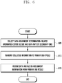
- FIG. 6 is a flowchart illustrating a transmission data assignment procedure of a secondary eNB (e.g., eNB 315 and eNB 435) hosting an SCell according to an embodiment of the present invention. This procedure may be implemented by a controller included in the eNB.
- a secondary eNB e.g., eNB 315 and eNB 435
- This procedure may be implemented by a controller included in the eNB.
- the secondary eNB may collect related information for determining whether data assignment is necessary.
- the secondary eNB may store at least one of its BO size and data rate.
- the secondary eNB may send the collected related information to the primary eNB (e.g., eNB 310 and eNB 405) hosting the PCell.
- the primary eNB e.g., eNB 310 and eNB 405
- the secondary eNB may receive, at step 615, the data assigned to the secondary eNB and RLC SNs from the primary eNB.
- the secondary eNB may send the UE the data assigned to the secondary eNB using the RLC SNs assigned to the secondary eNB.
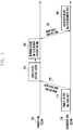
- FIG. 7 is a diagram illustrating an operation of assigning transmission data to eNBs according to an embodiment of the present invention.
- the secondary eNB 710 hosting an SCell may collect at least one of BO size and data rate of the secondary eNB.
- the secondary eNB 710 may send the primary eNB 705 the collected BO size and data rate.
- the primary eNB 705 hosting the PCell may collect related information for determining whether data assignment to the eNBs is necessary.
- the primary eNB 705 may collect at least one of the BO size and data rate of the primary eNB 705 and receive the BO size and data rate of the secondary eNB 710 from the second eNB 710. It may also be possible to measure the latency in communication with the secondary eNB.
- the primary eNB 705 may determine data and RLC SNs to be assigned to the respective eNBs based on the collected related information.
- the primary eNB 705 may store the data and RLC SNs assigned to itself.
- the primary eNB 705 may send the UE the data using the RLC SNs assigned to itself.
- the primary eNB 705 may send the secondary eNB 710 the data assigned to the secondary eNB 710 and the RLC SNs assigned to the corresponding data.
- the secondary eNB 710 may receive the data and RLC SN sent by the primary eNB 705.
- the secondary eNB 710 may send the UE the data assigned to itself using the received RLC SNs.
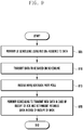
- FIG. 8 is a flowchart illustrating a UE scheduling procedure of a primary eNB (e.g., eNB 310 and eNB 405) hosting the PCell according to an embodiment of the present invention.
- the procedure depicted in FIG. 8 may be performed subsequent to the procedure depicted in FIG. 5 .
- the primary eNB may perform UE scheduling using the RLC SNs assigned to the data assigned to itself.
- the primary eNB may send the UE the data based on the scheduling.
- the primary eNB may receive a HARQ ACK/NACK corresponding to the data from the UE. Since the ACK/NACK corresponding to the data sent through the SCell as well as the ACK/NACK corresponding to the data sent through the PCell are all delivered through the PCell, the primary eNB receives all of the ACK/NACK corresponding to the data assigned to the primary data and the ACK/NACK corresponding to the data assigned to the secondary eNB. The primary eNB may forward the ACK/NACK corresponding to the data assigned to the secondary eNB to the secondary eNB.
- the primary eNB may perform the UE scheduling to transmit new data for the case of receiving the ACK corresponding to the data transmitted thereby and retransmit the previously transmitted data for the case of receiving the NACK corresponding to the data transmitted thereby.
- FIG. 9 is a flowchart illustrating a UE scheduling procedure of a secondary eNB (e.g., eNB 315 and eNB 435) hosting an SCell according to an embodiment of the present invention.
- the procedure depicted in FIG. 9 may be performed subsequent to the procedure depicted in FIG. 6 .
- the secondary eNB may perform UE scheduling using the RLC SNs assigned to the data assigned to itself.
- the secondary eNB may send the data to the UE based on the scheduling.
- the secondary eNB may receive an HARQ ACK/NACK corresponding to the data from the primary eNB hosting the PCell.
- the secondary eNB may perform the UE scheduling to transmit new data for the case of receiving the ACK corresponding to the data transmitted by the secondary eNB and retransmit the previously transmitted data for the case of receiving the NACK corresponding to the data transmitted by the secondary eNB.
- FIG. 10 is a diagram illustrating UE scheduling operations of eNBs according to an embodiment of the present invention.
- the primary eNB 1005 hosting the PCell may perform UE scheduling for sending data assigned to itself.
- the secondary eNB 1010 hosting an SCell may perform UE scheduling to transmit data assigned to itself.
- the primary eNB 1005 may receive an ACK/NACK corresponding to the transmitted data assigned to the primary eNB.
- the primary eNB 1005 may also receive an ACK/NACK corresponding to the transmitted data assigned to the secondary eNB. This is because all of the ACK/NACKs corresponding to the data transmitted through the PCell and SCell are received through the PCell.
- the primary eNB 1005 may send the ACK/NACK corresponding to the transmitted data assigned to the secondary eNB to the secondary eNB 1010.
- the secondary eNB 1010 may receive the ACK/NACK transmitted by the primary eNB 1005.
- the primary eNB 1005 may perform UE scheduling based on the ACK/NACK corresponding to the transmitted data assigned to the primary eNB 1005. For example, the primary eNB 1005 may perform the UE scheduling to transmit new data for the case of receiving the ACK corresponding to the data transmitted thereby and retransmit the previously transmitted data for the case of receiving the NACK corresponding to the data transmitted thereby.
- the secondary eNB 1010 may perform UE scheduling based on the ACK/NACK corresponding to the transmitted data assigned to the secondary eNB. For example, the secondary eNB 1010 may perform the UE scheduling to transmit new data for the case of receiving the ACK corresponding to the data transmitted thereby and retransmit the previously transmitted data for the case of receiving the NACK corresponding to the data transmitted thereby.
- FIG. 11 is a diagram for explaining a scheduling method for handing an RLC SN assignment error according to an embodiment of the present invention.
- assigned RLC SNs may become surplus or lacking for the allocated resources.
- the eNB may assign multiple SNs to one subframe as denoted by reference number 1105 for the case where the RLC SNs are surplus or perform RLC segmentation to assign an SN to multiple subframes as denoted by reference number 1110 for the case where the RLC SNs are lacking.
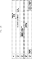
- FIGs. 12A to 12C are diagrams for explaining HARQ process timings of SCell downlink data.
- FIG. 12A shows a cell-specific HARQ process according to LTE standards. It may be possible to transmit data, receive a HARQ ACK/NACK corresponding to the data through PCell uplink after a predetermined time period, and perform HARQ retransmission with the same HARQ process ID or new data transmission according to the ACK/NACK result.
- the RLC/MAC/PHY process has to be completed during a period before data transmission after the receipt of the ACK/NACK.
- the RLC/MAC/PHY process may include ACK/NACK result delivery from PHY to MAC, resource allocation at MAC, resource allocation result transfer from MAC to RLC, RLC SN assignment and MAC PDU generation, MAC PDU transfer from RLC to PHY, and transmission data generation at PHY.
- FIG. 12B shows an example of HARQ processing for SCell downlink data according to LTE standards.
- a CA technique is applied to different eNBs (i.e., PCell and SCell are hosted by different eNBs), it may be assumed that the RLC entity located in the PCell is used.
- the eNB hosting the PCell and the eNB hosting the SCell have to perform signaling at least three times according to the RLC/MAC/PHY processing procedure described with reference to FIG. 12A .
- Latency there are several types of latency including X2 delay between the eNBs and, if the latency increases, it may become difficult to complete the RLC/MAC/PHY process in the given time period and to use the same HARQ process ID as used in the previous transmission. This may cause HARQ process ID shortage and data allocation failure to subframes in a situation where a single UE exists in an LTE standard supporting use of up to 8 HARQ process IDs.
- FIG. 12C shows an example of HARQ processing for SCell downlink data according to an embodiment of the present invention.
- the SCell may be influenced by the inter-eNB latency caused by transmission of a resource allocation result, RLC SNs, and data in the RLC/MAC/PHY process. As a consequence, it is possible to use network resources efficiently.
- the SCell ACK/NACK delay may still exist even though the present invention is applied, it may fail in allocating a bearer to the SCell at a corresponding time point as HARQ IDs become insufficient.
Abstract
Description
- The present invention relates to a wireless communication system supporting carrier aggregation and, in particular, to a method and apparats for transmitting data to a terminal over multiple carriers.
- The mobile communication system has been developed for the user to communicate on the move. With the rapid advance of technologies, the mobile communication system has evolved to the level capable of providing high speed data communication services as well as a voice telephony service.
- Recently, standardization for a long-term evolution (LTE) system, as one of the next-generation mobile communication systems, has been underway in the 3rd generation partnership project (3GPP). LTE is a technology for realizing high-speed packet-based communications at a data rate of up to 100 Mbps, which is higher than the currently available data rate, and its standardization is almost complete.
- For improving data rates, recent studies are focused on LTE-Advanced (LTE-A) with the adoption of various new techniques to the legacy LTE system. One of such technologies is Carrier Aggregation. Unlike the conventional technology of using one downlink carrier and one uplink carrier for data communication, Carrier Aggregation is a technology allowing a terminal to use multiple downlink carriers and multiple uplink carriers.
- In the case where multiple base stations transmit data over aggregated frequency resources, however, inter-base station latencies may cause data transmission resource waste.
- The present invention has been conceived to solve at least part of the above problem and aims to provide a method and apparatus for distributing, in advance, data and sequence numbers for the corresponding data to protect against data transmission resource waste caused by latencies among the base stations that transmit the data over aggregated frequency resources.
- In accordance with an aspect of the present invention, a data transmission method of a base station in a wireless communication system supporting carrier aggregation includes identifying whether a condition for assigning data to be transmitted is fulfilled; determining, if the condition is fulfilled, radio link control (RLC) data to be assigned to the base station and any other base station and sequence numbers associated with the RLC data; and transferring the RLC data and sequence numbers assigned to the any other base station.
- In accordance with another aspect of the present invention, a data transmission method of a base station in a wireless communication system supporting carrier aggregation includes receiving, if a condition for assigning data to be transmitted is fulfilled, radio link control (RLC) data assigned to the base station and sequence numbers associated with the RLC data from any other base station; and performing terminal scheduling based on the received RLC data and sequence numbers.
- In accordance with another aspect of the present invention, a base station of a wireless communication system supporting carrier aggregation includes a communication unit configured to transmit and receive signals and a controller configured to control to identify whether a condition for assigning data to be transmitted is fulfilled; determine, if the condition is fulfilled, radio link control (RLC) data to be assigned to the base station and any other base station and sequence numbers associated with the RLC data; and transfer the RLC data and sequence numbers assigned to the any other base station.
- In accordance with still another aspect of the present invention, a base station of a wireless communication system supporting carrier aggregation includes a communication unit configured to transmit and receive signals and a controller configured to control to receive, if a condition for assigning data to be transmitted is fulfilled, radio link control (RLC) data assigned to the base station and sequence numbers associated with the RLC data from any other base station and perform terminal scheduling based on the received RLC data and sequence numbers.
- The present invention is advantageous in terms of improving network resource utilization efficiency, when multiple base stations transmit data over aggregated frequency resources, by assigning data and sequence numbers for the corresponding data among the base stations.
-
-
FIG. 1 is a schematic diagram illustrating architecture of an LTE system; -
FIG. 2 is a diagram illustrating a protocol stack for use in an LTE system; -
FIG. 3 is a conceptual diagram illustrating an inter-eNB frequency resource allocation procedure according to an embodiment of the present invention; -
FIG. 4 is a diagram illustrating schematic configurations of a primary eNB and a secondary eNB according to an embodiment of the present invention; -
FIG. 5 is a flowchart illustrating a transmission data assignment procedure of a primary eNB hosting the PCell according to an embodiment of the present invention; -
FIG. 6 is a flowchart illustrating a transmission data assignment procedure of a secondary eNB hosting an SCell according to an embodiment of the present invention; -
FIG. 7 is a diagram illustrating an operation of assigning transmission data to eNBs according to an embodiment of the present invention; -
FIG. 8 is a flowchart illustrating a UE scheduling procedure of a primary eNB hosting the PCell according to an embodiment of the present invention; -
FIG. 9 is a flowchart illustrating a UE scheduling procedure of a secondary eNB hosting an SCell according to an embodiment of the present invention; -
FIG. 10 is a diagram illustrating UE scheduling operations of eNBs according to an embodiment of the present invention; -
FIG. 11 is a diagram for explaining a scheduling method for handling an RLC SN assignment error according to an embodiment of the present invention; -
FIG. 12A is a diagram illustrating HARQ process timings in an LTE system; -
FIG. 12B is a diagram for explaining timing delay in a SCell downlink data HARQ process; and -
FIG. 12C is a diagram illustrating SCell downlink data HARQ process timings according to an embodiment of the present invention. - Exemplary embodiments of the present invention are described in detail with reference to the accompanying drawings. The same reference numbers are used throughout the drawings to refer to the same or like parts. Detailed descriptions of well-known functions and structures incorporated herein may be omitted to avoid obscuring the subject matter of the present invention.
- Although the description is directed to the advanced E-UTRA (or LTE-A) supporting carrier aggregation, it will be understood by those skilled in the art that the subject matter of the present invention can be applied also to other communication systems having a similar technical background and channel format, with a slight modification, without departing from the spirit and scope of the present invention. For example, the subject matter of the present invention is applicable to the multicarrier HSPA supporting carrier aggregation.
- The embodiments disclosed in the specification and drawings are proposed to help explain and understand the present invention rather than to limit the scope of the present invention. It is obvious to those skilled in the art that various modifications and changes can be made thereto without departing from the broader spirit and scope of the invention.
- Various embodiments of the present invention relate to method and apparatuses for carrier aggregation (CA) among multiple base stations and are directed to downlink data transmission in a wireless communication system.
- According to various embodiments, CA may include all the types of frequency resource aggregation techniques including Rel-12 dual connectivity (DC), Rel-12 TDD-FDD CA, Rel-13 licensed assisted access (LAA), TDD-FDD dual connectivity, LTE-U supplement downlink (SDL), LTE-U CA, LTE-WLAN aggregation, and LTE-Wi-Fi aggregation, as well as Rel-10 CA of 3GPP LTE standard.
-
FIG. 1 is a schematic diagram illustrating architecture of an LTE system. - In reference to
FIG. 1 , the radio access network of the LTE system includes evolved node Bs (hereinafter, interchangeably referred to as eNB, node B, and base station) 105, 110, 115, and 120, a mobility management entity (MME) 125, and a serving-gateway (S-GW) 130. The user equipment (hereinafter, interchangeably referred to as UE and terminal) 135 connects to an external network via the eNBs 105, 110, 115, and 120 and the S-GW 130. - In
FIG. 1 , the eNBs 105, 110, 115, and 120 correspond to legacy node Bs of a UMTS system. The UE 135 connects to eNBs 105, 110, 115, and 120 through a radio channel, and the eNBs 105, 110, 115, and 120 have functions more complex than those of the legacy node B. In the LTE system where all user traffic including real time services such as Voice over IP (VoIP) is served through shared channels, it is necessary to schedule UEs based on scheduling information such as buffer status, power headroom status, and channel status collected from the UEs, and an eNB serving the UEs takes charge of this function. Typically, one eNB operates multiple cells. The LTE system adopts orthogonal frequency division multiplexing (OFDM) as a radio access technology to secure a data rate of up to 100 Mbps in a bandwidth of 20 MHz. The LTE system also adopts Adaptive Modulation and Coding (AMC) to determine the modulation scheme and channel coding rate in adaptation to the channel condition of the UE. - The S-GW 130 handles data bearer functions to establish and release data bearers under the control of the
MME 125. - The MME 125 handles various control functions as well as the mobile management function and has connections with the eNBs.
-
FIG. 2 is a diagram illustrating a protocol stack for use in a LTE system. - In reference to
FIG. 2 , the protocol stack of the interface between the UE and the eNB in the LTE system includes a physical layer denoted byreference numbers reference numbers reference numbers reference numbers - The PDCP layer denoted by
reference numbers - The RLC layer denoted by
reference numbers - The MAC layer denoted by
reference number - The PHY layer denoted by
reference numbers - A schematic description is made of the 3GPP LTE Rel-10 CA technique hereinafter.
- In Rel-10 CA, the UE may have frequency specific-cells including a primary cell (PCell), which uniquely allows for an RRC connection, and other cells called secondary cells (SCells). When CA is configured, multi-frequency characteristics are observed at the MAC/PHY/RF layer but are transparent to the higher layers above the MAC layer in view of the downlink (DL) layer-2 structure. That is, the PDCP and RLC layer entities are established regardless of the number of carriers, while as many of the MAC/PHY/RF layer entities are established as the number of carriers.
- If the Rel-10 CA technique is applied to different eNBs (e.g., PCell and SCells are hosted by different eNBs), it may be assumed that the individual eNBs use the RLC located at the eNB hosting the PCell. Here, since the MAC/PHY entities associated with the RLC entity are located at different eNBs, there is a need of signal exchange between the eNB hosting the PCell and the eNBs hosting the SCells according to the RLC/MAC/PHY processing procedure. In this case, there are likely to be several types of latency including X2 delay among the eNBs, which cause degradation of data transmission efficiency.
- The present invention proposes a method for utilizing network resources efficiently through inter-eNB frequency resource aggregation, and this is explained in various embodiments.
- The methods and apparatus explained in the various embodiments of the present invention may be applied for utilizing SCell resources efficiently in the Rel-10 CA-based inter-eNB frequency resource aggregation and other inter-eNB frequency resource aggregation techniques including Rel-12 DC-based inter-eNB frequency resource aggregation.
- According to an embodiment of the present invention, an eNB has a virtual RLC to support inter-eNB frequency aggregation.
- An embodiment of the present invention is directed to an algorithm for assigning data to different eNBs in advance to support inter-eNB carrier aggregation.
- In the following descriptions, the terms "primary eNB" and "secondary eNB" are used; the term "eNB" denotes a device that communicates with UEs and controls the operations of the UEs, and it may be assumed that the first eNB establishes an RRC connection. That is, an eNB hosting a PCell is referred to as a primary eNB, and an eNB hosting an SCell is referred to as secondary eNB. There exists only one primary eNB per bearer and one or more secondary eNBs. It is not essential for an eNB to host only one cell, i.e., the eNB may host multiple cells with respective frequencies.
- The present invention is applicable to all the types of frequency resource aggregation techniques, e.g., Rel-10 CA by substituting the terms "PCell" and "SCell" for the terms "primary eNB" and "secondary eNB," respectively, and Rel-12 DC by substituting the terms "MeNB" and "SeNB" for the terms "primary eNB" and "secondary eNB," respectively.
- In the legacy Rel-10 CA technique, even the data to be transmitted to the UE via the secondary eNBs without a PCell are stored in an RLC located in the primary eNB, and MAC PDUs carrying SCell downlink data are generated by the corresponding RLC.
- In the present invention, however, the SCell downlink data may be stored in a virtual RLC entity located in the secondary eNB, in advance, according to a data pre-assignment algorithm. The MAC PDUs carrying the SCell downlink data may be generated by the virtual RLC. This may allow the inter-eNB latency caused by delivery of SCell resource allocation result, RLC sequence number (SN), and MAC PDUs to be cancelled. However, the ACK/NACK that is transmitted only through the PCell should be transferred from the PCell to the SCell.
FIG. 3 is a conceptual diagram illustrating an inter-eNB frequency resource allocation procedure according to an embodiment of the present invention. - The
primary eNB 310 and thesecondary eNB 315 are connected to each other through a wireless or wirednetwork 320 to exchange signals. The S-GW 305 establishes a data bearer with theprimary eNB 310 hosting the PCell. - The RLC of the
primary eNB 310 assigns downlink RLC data to the primary and secondary eNBs 310 and 320 along with RLC SNs as denoted byreference number 325. The RLC entity of theprimary eNB 310 sends the RLC data and corresponding RLC SNs assigned to thesecondary eNB 315 to the virtual RLC of thesecondary eNB 315. Also, the RLC of theprimary eNB 310 sends ACK/NACK corresponding to the SCell downlink data to thevirtual RLC 335. -
FIG. 4 is a diagram illustrating schematic configurations of a primary eNB and a secondary eNB according to an embodiment of the present invention. According to this embodiment, there may be multiple secondary eNBs hosting respective SCells and, in this case, the secondary eNBs are referred to as first secondary eNB, second secondary eNB, ..., and Nth secondary eNB that are collectively called secondary eNBs. - Each of the primary and secondary eNBs 405 and 435 may include a communication unit for communicating signals and a controller for controlling the communication unit and overall operations to implement the present invention. For example, the communication unit may include an
RF module PDCP processing unit 410, anRLC processing unit 415, a virtualRLC processing unit 440, aMAC processing unit PHY processing unit - According to an embodiment of the present invention, the
primary eNB 405 may include aPDCP processing unit 410, anRLC processing unit 415, aMAC processing unit 420, aPHY processing unit 425, and anRF module 430. - The
PDCP processing unit 410 is responsible for IP header compression/ decompression. - The
RLC processing unit 415 is responsible for reformatting PDCP PDUs for ARQ operation. According to an embodiment of the present invention, theRLC processing unit 415 may be responsible for a data pre-assignment function for assigning data, in advance, to eNBs in CA mode. - The
RLC processing unit 415 may collect and manage information for use in determining whether to perform the data pre-assignment. TheRLC processing unit 415 may determine to perform the data pre-assignment based on the information and assign data to the eNBs based on the determination result. TheRLC processing unit 415 may send the corresponding eNBs the data along with corresponding RLC SNs. - According to an embodiment of the present invention, the
RLC processing unit 415 of theprimary eNB 405 may perform the data pre-assignment per radio bearer periodically when there are data to be transmitted to the UE. According to various embodiments of the present invention, the data pre-assignment may be performed by thePDCP processing unit 410. - The information for use in determining whether to perform the data pre-assignment may include at least one of eNB-specific buffer occupancy (BO) size (BOn denotes BO of the nth eNB), latency (dn denotes latency between the first eNB and the nth eNB), and data rate (Tn denotes the data rate from the nth eNB to the UE). Here, n may indicate one of a primary, a first secondary, a second secondary, ..., and Nth secondary eNBs. The
RLC processing unit 415 may determine whether a data pre-assignment condition is satisfied per eNB. In this case, BOn, dn, and Tn are used as shown in formula (1).
- If one or more eNBs meet the data pre-assignment condition, the primary eNB determines the data size (Sn) to be pre-assigned to the eNB and a number of RLC SNs (Rn) to be assigned to the eNB based on BOn, dn, and Tn as shown in formula (2).

- For example, the size of data and the number of SNs to be assigned to an eNB may increase as the BO size of the eNB decreases or the data rate increases; the size of data and the number of RLC SNs to be assigned to an eNB may decrease as the latency with the first eNB increases.
- The
RLC processing unit 415 may control such that the RLC data and corresponding RLC SNs assigned to thesecondary eNB 435 as a result of the data pre-assignment are transmitted to thevirtual RLC 440 of thesecondary eNB 435. - The
MAC processing unit 420 multiplexes RLC PDUs into a MAC PDU and demultiplexes a MAC PDU into RLC PDUs and is responsible for resource allocation. - The
PHY processing unit 425 is responsible for channel coding and modulation on higher layer data to generate and transmit OFDM symbols over a radio channel and demodulating and channel decoding on OFDM symbols received over the radio channel to deliver the decoded data to the higher layers. - According to an embodiment of the present invention, the
secondary eNB 435 may include a virtualRLC processing unit 440, aMAC processing unit 445, aPHY processing unit 450, and anRF module 455. - The virtual
RLC processing unit 440 may perform the RLC functions for the cell hosted by thesecondary eNB 435. The virtualRLC processing unit 440 may send the primary eNB the information necessary for use in determining whether to perform data pre-assignment. For example, this information may include at least one of a BO size and data rate of the secondary eNB. - The virtual
RLC processing unit 440 may store the RLC data and corresponding RLC SNs transmitted by theRLC processing unit 415 of theprimary eNB 405 according to the result of the data pre-assignment. The virtualRLC processing unit 440 may generate MAC PDUs containing downlink data addressed to the UE based on the stored RLC data and corresponding RLC SNs. Here, the RLC SN may be assigned per MAC PDU based on RLC SN information. - The
MAC processing unit 445 multiplexes RLC PDUs into a MAC PDU and demultiplexes a MAC PDU into RLC PDUs and is responsible for resource allocation. - The
PHY processing unit 450 is responsible for channel-coding and modulation on higher layer data to generate and transmit OFDM symbols over a radio channel and demodulating and channel-decoding on OFDM symbols received over the radio channel to deliver the decoded data to the higher layers. -
FIG. 5 is a flowchart illustrating a transmission data assignment procedure of a primary eNB (e.g.,eNB 310 and eNB 405) hosting the PCell according to an embodiment of the present invention. This procedure may be implemented by a controller included in the eNB. - At
step 505, the primary eNB may collect related information for determining whether data assignment to a secondary eNB (e.g.,eNB 315 and eNB 435) is necessary. As aforementioned, the collected related information may include at least one of BO size, latency in communication with the primary eNB, and data rate per eNB. The primary eNB may store its BO size and data rate and receive the BO size and data rate of the secondary eNB from the secondary eNB. The primary eNB may measure the latency between the primary and secondary eNBs. - At
step 510, the primary eNB may determine whether a data assignment execution condition is fulfilled for the secondary eNB based on the collected related information. For example, the primary eNB may determine whether the data assignment execution condition is fulfilled based on formula (1). - If the data assignment execution condition is fulfilled, the primary eNB may determine, at
step 515, the data size and number of RLC SNs to be assigned per eNB. The data size and number of RLC SNs to be assigned per eNB may be determined based on equation (2) described above. Accordingly, the RLC SNs may be assigned to the data integrally rather than independently in association with the primary and secondary eNBs. Thus, the UE may receive and arrange the data transmitted by the primary and secondary eNBs based on the integral RLC SNs. - At
step 520, the primary eNB may store the data and RLC SNs assigned to the primary eNB and transfer the data and RLC SN assigned to the secondary eNB to the secondary eNB. - Afterward, the primary eNB may send the UE the data assigned to the primary eNB using the RLC SNs assigned to the primary eNB.
-
FIG. 6 is a flowchart illustrating a transmission data assignment procedure of a secondary eNB (e.g.,eNB 315 and eNB 435) hosting an SCell according to an embodiment of the present invention. This procedure may be implemented by a controller included in the eNB. - At
step 605, the secondary eNB may collect related information for determining whether data assignment is necessary. For example, the secondary eNB may store at least one of its BO size and data rate. - At
step 610, the secondary eNB may send the collected related information to the primary eNB (e.g.,eNB 310 and eNB 405) hosting the PCell. - After the primary eNB assigns data and RLC SNs based on the data assignment determination-related information, the secondary eNB may receive, at
step 615, the data assigned to the secondary eNB and RLC SNs from the primary eNB. - Afterward, the secondary eNB may send the UE the data assigned to the secondary eNB using the RLC SNs assigned to the secondary eNB.
-
FIG. 7 is a diagram illustrating an operation of assigning transmission data to eNBs according to an embodiment of the present invention. - At
step 715, thesecondary eNB 710 hosting an SCell may collect at least one of BO size and data rate of the secondary eNB. Atstep 720, thesecondary eNB 710 may send theprimary eNB 705 the collected BO size and data rate. - At
step 725, theprimary eNB 705 hosting the PCell may collect related information for determining whether data assignment to the eNBs is necessary. For example, theprimary eNB 705 may collect at least one of the BO size and data rate of theprimary eNB 705 and receive the BO size and data rate of thesecondary eNB 710 from thesecond eNB 710. It may also be possible to measure the latency in communication with the secondary eNB. - At
step 730, theprimary eNB 705 may determine data and RLC SNs to be assigned to the respective eNBs based on the collected related information. Theprimary eNB 705 may store the data and RLC SNs assigned to itself. Theprimary eNB 705 may send the UE the data using the RLC SNs assigned to itself. - At
step 735, theprimary eNB 705 may send thesecondary eNB 710 the data assigned to thesecondary eNB 710 and the RLC SNs assigned to the corresponding data. - At
step 740, thesecondary eNB 710 may receive the data and RLC SN sent by theprimary eNB 705. Thesecondary eNB 710 may send the UE the data assigned to itself using the received RLC SNs. -
FIG. 8 is a flowchart illustrating a UE scheduling procedure of a primary eNB (e.g.,eNB 310 and eNB 405) hosting the PCell according to an embodiment of the present invention. The procedure depicted inFIG. 8 may be performed subsequent to the procedure depicted inFIG. 5 . - At
step 805, the primary eNB may perform UE scheduling using the RLC SNs assigned to the data assigned to itself. - At
step 810, the primary eNB may send the UE the data based on the scheduling. - At
step 815, the primary eNB may receive a HARQ ACK/NACK corresponding to the data from the UE. Since the ACK/NACK corresponding to the data sent through the SCell as well as the ACK/NACK corresponding to the data sent through the PCell are all delivered through the PCell, the primary eNB receives all of the ACK/NACK corresponding to the data assigned to the primary data and the ACK/NACK corresponding to the data assigned to the secondary eNB. The primary eNB may forward the ACK/NACK corresponding to the data assigned to the secondary eNB to the secondary eNB. - At
step 820, the primary eNB may perform the UE scheduling to transmit new data for the case of receiving the ACK corresponding to the data transmitted thereby and retransmit the previously transmitted data for the case of receiving the NACK corresponding to the data transmitted thereby. -
FIG. 9 is a flowchart illustrating a UE scheduling procedure of a secondary eNB (e.g.,eNB 315 and eNB 435) hosting an SCell according to an embodiment of the present invention. The procedure depicted inFIG. 9 may be performed subsequent to the procedure depicted inFIG. 6 . - At
step 905, the secondary eNB may perform UE scheduling using the RLC SNs assigned to the data assigned to itself. - At
step 910, the secondary eNB may send the data to the UE based on the scheduling. - At
step 915, the secondary eNB may receive an HARQ ACK/NACK corresponding to the data from the primary eNB hosting the PCell. - At
step 920, the secondary eNB may perform the UE scheduling to transmit new data for the case of receiving the ACK corresponding to the data transmitted by the secondary eNB and retransmit the previously transmitted data for the case of receiving the NACK corresponding to the data transmitted by the secondary eNB. -
FIG. 10 is a diagram illustrating UE scheduling operations of eNBs according to an embodiment of the present invention. - At
step 1015, theprimary eNB 1005 hosting the PCell may perform UE scheduling for sending data assigned to itself. Atstep 1020, thesecondary eNB 1010 hosting an SCell may perform UE scheduling to transmit data assigned to itself. - At
step 1025, theprimary eNB 1005 may receive an ACK/NACK corresponding to the transmitted data assigned to the primary eNB. Atstep 1030, theprimary eNB 1005 may also receive an ACK/NACK corresponding to the transmitted data assigned to the secondary eNB. This is because all of the ACK/NACKs corresponding to the data transmitted through the PCell and SCell are received through the PCell. - At
step 1035, theprimary eNB 1005 may send the ACK/NACK corresponding to the transmitted data assigned to the secondary eNB to thesecondary eNB 1010. Thesecondary eNB 1010 may receive the ACK/NACK transmitted by theprimary eNB 1005. - Then, the
primary eNB 1005 may perform UE scheduling based on the ACK/NACK corresponding to the transmitted data assigned to theprimary eNB 1005. For example, theprimary eNB 1005 may perform the UE scheduling to transmit new data for the case of receiving the ACK corresponding to the data transmitted thereby and retransmit the previously transmitted data for the case of receiving the NACK corresponding to the data transmitted thereby. - The
secondary eNB 1010 may perform UE scheduling based on the ACK/NACK corresponding to the transmitted data assigned to the secondary eNB. For example, thesecondary eNB 1010 may perform the UE scheduling to transmit new data for the case of receiving the ACK corresponding to the data transmitted thereby and retransmit the previously transmitted data for the case of receiving the NACK corresponding to the data transmitted thereby. -
FIG. 11 is a diagram for explaining a scheduling method for handing an RLC SN assignment error according to an embodiment of the present invention. - According to this embodiment, when there is a failure to predict accurately the number of RLC SNs to be assigned to each eNB (e.g., primary eNB or secondary eNB) for use in transmitting data to the UE, assigned RLC SNs may become surplus or lacking for the allocated resources.
- The eNB may assign multiple SNs to one subframe as denoted by
reference number 1105 for the case where the RLC SNs are surplus or perform RLC segmentation to assign an SN to multiple subframes as denoted byreference number 1110 for the case where the RLC SNs are lacking. -
FIGs. 12A to 12C are diagrams for explaining HARQ process timings of SCell downlink data. -
FIG. 12A shows a cell-specific HARQ process according to LTE standards. It may be possible to transmit data, receive a HARQ ACK/NACK corresponding to the data through PCell uplink after a predetermined time period, and perform HARQ retransmission with the same HARQ process ID or new data transmission according to the ACK/NACK result. - Accordingly, the RLC/MAC/PHY process has to be completed during a period before data transmission after the receipt of the ACK/NACK. For example, the RLC/MAC/PHY process may include ACK/NACK result delivery from PHY to MAC, resource allocation at MAC, resource allocation result transfer from MAC to RLC, RLC SN assignment and MAC PDU generation, MAC PDU transfer from RLC to PHY, and transmission data generation at PHY.
-
FIG. 12B shows an example of HARQ processing for SCell downlink data according to LTE standards. - If a CA technique is applied to different eNBs (i.e., PCell and SCell are hosted by different eNBs), it may be assumed that the RLC entity located in the PCell is used. Here, since the RLC entity and the MAC/PHY entities of the SCell are located at different eNBs, the eNB hosting the PCell and the eNB hosting the SCell have to perform signaling at least three times according to the RLC/MAC/PHY processing procedure described with reference to
FIG. 12A . That is, it is necessary to send the ACK/NACK from the PHY of the PCell to the MAC of the SCell, send the resource allocation result from the MAC of the SCell to the RLC of the PCell, and assign RLC SNs and generate a MAC PDU at the RLC entity and send the MAC PDU from the RLC to the PHY of the SCell. - However, there are several types of latency including X2 delay between the eNBs and, if the latency increases, it may become difficult to complete the RLC/MAC/PHY process in the given time period and to use the same HARQ process ID as used in the previous transmission. This may cause HARQ process ID shortage and data allocation failure to subframes in a situation where a single UE exists in an LTE standard supporting use of up to 8 HARQ process IDs.
-
FIG. 12C shows an example of HARQ processing for SCell downlink data according to an embodiment of the present invention. - By applying an embodiment of the present invention to the Rel-10 CA, it may be possible for the respective eNBs to secure downlink data in advance. Accordingly, the SCell may be influenced by the inter-eNB latency caused by transmission of a resource allocation result, RLC SNs, and data in the RLC/MAC/PHY process. As a consequence, it is possible to use network resources efficiently. However, since the SCell ACK/NACK delay may still exist even though the present invention is applied, it may fail in allocating a bearer to the SCell at a corresponding time point as HARQ IDs become insufficient.
- The embodiments disclosed in the specification and drawings are proposed to help explain and understand the present invention rather than to limit the scope of the present invention. Thus, the scope of the invention should be determined by the appended claims and their legal equivalents rather than the specification, and various alterations and modifications within the definition and scope of the claims are included in the claims.
Claims (15)
- A data transmission method of a base station in a wireless communication system supporting carrier aggregation, the method comprising:identifying whether a condition for assigning data to be transmitted is fulfilled;determining, if the condition is fulfilled, radio link control (RLC) data to be assigned to the base station and any other base station and sequence numbers associated with the RLC data; andtransferring the RLC data and sequence numbers assigned to the any other base station.
- The method of claim 1, wherein identifying whether the condition for assigning data to be transmitted is fulfilled comprises identifying whether the condition is fulfilled based on at least one of buffer occupancy information of the base station and the any other base station, latency information between the base station and the any other base station, and data rate information of the base station and the any other base station.
- The method of claim 1, wherein determining the RLC data to be assigned to the any other base station comprises determining a size of data to be assigned to the any other base station based on at least one of buffer occupancy information of the base station and the any other base station, latency information between the base station and the any other base station, and data rate information of the base station and the any other base station.
- The method of claim 1, further comprising performing terminal scheduling based on the RLC data assigned to the base station and the sequence numbers, wherein performing the terminal scheduling comprises processing, if resource allocation error occurs in association with the RLC data assigned to the base station and the sequence numbers, multiple sequence numbers in one subframe or one sequence number in multiple sub frames.
- A data transmission method of a base station in a wireless communication system supporting carrier aggregation, the method comprising:receiving, if a condition for assigning data to be transmitted is fulfilled, radio link control (RLC) data assigned to the base station and sequence numbers associated with the RLC data from any other base station; andperforming terminal scheduling based on the received RLC data and sequence numbers.
- The method of claim 5, further comprising:collecting at least one of buffer occupancy information and data rate information of the base station; andsending the collected information to the any other base station.
- The method of claim 5, wherein whether the condition for assigning data to be transmitted is fulfilled is determined by the any other base station based on at least one of buffer occupancy information of the base station and the any other base station, latency information between the base station and the any other base station, and data rate information of the base station and the any other base station; and the RLC data and sequence numbers assigned to the base station are determined by the any other base station based on at least one of the buffer occupancy information of the base station and the any other base station, the latency information between the base station and the any other base station, and the data rate information of the base station and the any other base station.
- The method of claim 5, wherein performing the terminal scheduling comprises processing, if resource allocation error occurs in association with the RLC data assigned to the base station and the sequence numbers, multiple sequence numbers in one subframe or one sequence number in multiple subframes.
- A base station of a wireless communication system supporting carrier aggregation, the base station comprising:a communication unit configured to transmit and receive signals; anda controller configured to control to identify whether a condition for assigning data to be transmitted is fulfilled, determine, if the condition is fulfilled, radio link control (RLC) data to be assigned to the base station and any other base station and sequence numbers associated with the RLC data, and transfer the RLC data and sequence numbers assigned to the any other base station.
- The base station of claim 9, wherein the controller is configured to control to identify whether the condition is fulfilled based on at least one of buffer occupancy information of the base station and the any other base station, latency information between the base station and the any other base station, and data rate information of the base station and the any other base station.
- The base station of claim 9, wherein the controller is configured to control to determine a size of data to be assigned to the any other base station based on at least one of buffer occupancy information of the base station and the any other base station, latency information between the base station and the any other base station, and data rate information of the base station and the any other base station.
- The base station of claim 9, wherein the controller is configured to control to perform terminal scheduling based on the RLC data assigned to the base station and the sequence numbers and process, if resource allocation error occurs in association with the RLC data assigned to the base station and the sequence numbers, multiple sequence numbers in one subframe or one sequence number in multiple subframes.
- A base station of a wireless communication system supporting carrier aggregation, the base station comprising:a communication unit configured to transmit and receive signals; anda controller configured to control to receive, if a condition for assigning data to be transmitted is fulfilled, radio link control (RLC) data assigned to the base station and sequence numbers associated with the RLC data from any other base station and perform terminal scheduling based on the received RLC data and sequence numbers.
- The base station of claim 13, wherein the controller is configured to control to collect at least one of buffer occupancy information and data rate information of the base station and send the collected information to the any other base station; whether the condition for assigning data to be transmitted is fulfilled is determined by the any other base station based on at least one of buffer occupancy information of the base station and the any other base station, latency information between the base station and the any other base station, and data rate information of the base station and the any other base station; and the RLC data and sequence numbers assigned to the base station are determined by the any other base station based on at least one of the buffer occupancy information of the base station and the any other base station, the latency information between the base station and the any other base station, and the data rate information of the base station and the any other base station.
- The base station of claim 13, wherein the controller is configured to process, if resource allocation error occurs in association with the RLC data assigned to the base station and the sequence numbers, multiple sequence numbers in one subframe or one sequence number in multiple subframes.
Applications Claiming Priority (2)
| Application Number | Priority Date | Filing Date | Title |
|---|---|---|---|
| KR1020150162456A KR102448173B1 (en) | 2015-11-19 | 2015-11-19 | Method and apparatus for transmitting data in wireless communication system supporting carrier aggregation |
| PCT/KR2016/012997 WO2017086660A1 (en) | 2015-11-19 | 2016-11-11 | Method and apparatus for transmitting data in wireless communication system supporting carrier aggregation |
Publications (3)
| Publication Number | Publication Date |
|---|---|
| EP3340720A1 true EP3340720A1 (en) | 2018-06-27 |
| EP3340720A4 EP3340720A4 (en) | 2018-09-05 |
| EP3340720B1 EP3340720B1 (en) | 2022-02-09 |
Family
ID=58719026
Family Applications (1)
| Application Number | Title | Priority Date | Filing Date |
|---|---|---|---|
| EP16866612.1A Active EP3340720B1 (en) | 2015-11-19 | 2016-11-11 | Method and apparatus for transmitting data in wireless communication system supporting carrier aggregation |
Country Status (5)
| Country | Link |
|---|---|
| US (1) | US10555327B2 (en) |
| EP (1) | EP3340720B1 (en) |
| KR (1) | KR102448173B1 (en) |
| CN (1) | CN108353419B (en) |
| WO (1) | WO2017086660A1 (en) |
Cited By (1)
| Publication number | Priority date | Publication date | Assignee | Title |
|---|---|---|---|---|
| WO2020152497A1 (en) * | 2019-01-21 | 2020-07-30 | Telefonaktiebolaget Lm Ericsson (Publ) | Network nodes and methods supporting multiple connectivity |
Families Citing this family (2)
| Publication number | Priority date | Publication date | Assignee | Title |
|---|---|---|---|---|
| CN107113595A (en) * | 2014-12-31 | 2017-08-29 | 华为技术有限公司 | A kind of data transmission method, radio reception device and communication system |
| KR102543090B1 (en) | 2018-01-08 | 2023-06-14 | 삼성전자주식회사 | Apparatus and method for allocating resources in wireless communication system |
Family Cites Families (10)
| Publication number | Priority date | Publication date | Assignee | Title |
|---|---|---|---|---|
| JP4519817B2 (en) * | 2006-08-22 | 2010-08-04 | 株式会社エヌ・ティ・ティ・ドコモ | Base station and mobile station |
| JP2013520096A (en) * | 2010-02-12 | 2013-05-30 | インターデイジタル テクノロジー コーポレーション | Data partitioning between multiple sites |
| US8457010B2 (en) * | 2010-11-16 | 2013-06-04 | Edgecast Networks, Inc. | Request modification for transparent capacity management in a carrier network |
| US9173147B2 (en) * | 2013-01-18 | 2015-10-27 | Blackberry Limited | Communicating data using a local wireless access network node |
| KR102237240B1 (en) * | 2013-07-04 | 2021-04-07 | 한국전자통신연구원 | Methods of controlling for supporting dual connectivity in mobile communication system and apparatus for performing the same |
| KR102148243B1 (en) * | 2013-07-12 | 2020-08-26 | 팬텍 주식회사 | Method and apparatus of data control at radio link control layer in wireless communication system supporting dual connectivity |
| KR102133287B1 (en) * | 2013-07-26 | 2020-07-13 | 삼성전자 주식회사 | Apparatus and method for effective multi-carrier multi-cell scheduling in a mobile commuinication system |
| US9648514B2 (en) * | 2013-08-09 | 2017-05-09 | Blackberry Limited | Method and system for protocol layer enhancements in data offload over small cells |
| CN104853382B (en) * | 2014-02-18 | 2020-08-25 | 中兴通讯股份有限公司 | Information interaction method, system and base station |
| WO2015167546A1 (en) * | 2014-04-30 | 2015-11-05 | Hitachi, Ltd. | Transmission control for bearer split under dual connectivity |
-
2015
- 2015-11-19 KR KR1020150162456A patent/KR102448173B1/en active IP Right Grant
-
2016
- 2016-11-11 CN CN201680067567.8A patent/CN108353419B/en active Active
- 2016-11-11 WO PCT/KR2016/012997 patent/WO2017086660A1/en active Application Filing
- 2016-11-11 US US15/774,102 patent/US10555327B2/en active Active
- 2016-11-11 EP EP16866612.1A patent/EP3340720B1/en active Active
Cited By (1)
| Publication number | Priority date | Publication date | Assignee | Title |
|---|---|---|---|---|
| WO2020152497A1 (en) * | 2019-01-21 | 2020-07-30 | Telefonaktiebolaget Lm Ericsson (Publ) | Network nodes and methods supporting multiple connectivity |
Also Published As
| Publication number | Publication date |
|---|---|
| US20180317240A1 (en) | 2018-11-01 |
| WO2017086660A1 (en) | 2017-05-26 |
| KR102448173B1 (en) | 2022-09-28 |
| US10555327B2 (en) | 2020-02-04 |
| CN108353419A (en) | 2018-07-31 |
| EP3340720A4 (en) | 2018-09-05 |
| EP3340720B1 (en) | 2022-02-09 |
| CN108353419B (en) | 2022-01-21 |
| KR20170058635A (en) | 2017-05-29 |
Similar Documents
| Publication | Publication Date | Title |
|---|---|---|
| KR102033597B1 (en) | Method and apparatus for performing random access procedure in mobile communication system | |
| US20220408512A1 (en) | Method and apparatus for retransmitting uplink data configured in discontinuous reception in a wireless communication system | |
| US11736241B2 (en) | Method and device for processing HARQ feedback in a mobile communication system | |
| US9681432B2 (en) | Method and apparatus for deactivating secondary carriers in mobile communication system using carrier aggregation | |
| US9967784B2 (en) | Method and apparatus for transmitting/receiving signal in mobile communication system supporting a plurality of carriers | |
| CN107453847B (en) | Base station, terminal and method thereof in wireless communication system | |
| CN107257551B (en) | Method and apparatus for transceiving data using multiple carriers in mobile communication system | |
| US11843969B2 (en) | Method and device for processing buffer state report in wireless communication system using inter-eNB carrier aggregation technology | |
| EP2637332A2 (en) | Method and device for activating secondary carrier in wireless communication system for using carrier aggregation technique | |
| EP3416447A1 (en) | Method and apparatus for accelerating data processing in wireless communication system | |
| JPWO2015141478A1 (en) | User equipment and uplink data transmission method | |
| KR20110111984A (en) | An efficient uplink contention based access in a wireless communication system | |
| US10142253B2 (en) | Method for efficient reliable transmission | |
| EP3340720B1 (en) | Method and apparatus for transmitting data in wireless communication system supporting carrier aggregation |
Legal Events
| Date | Code | Title | Description |
|---|---|---|---|
| STAA | Information on the status of an ep patent application or granted ep patent |
Free format text: STATUS: THE INTERNATIONAL PUBLICATION HAS BEEN MADE |
|
| PUAI | Public reference made under article 153(3) epc to a published international application that has entered the european phase |
Free format text: ORIGINAL CODE: 0009012 |
|
| STAA | Information on the status of an ep patent application or granted ep patent |
Free format text: STATUS: REQUEST FOR EXAMINATION WAS MADE |
|
| 17P | Request for examination filed |
Effective date: 20180321 |
|
| AK | Designated contracting states |
Kind code of ref document: A1 Designated state(s): AL AT BE BG CH CY CZ DE DK EE ES FI FR GB GR HR HU IE IS IT LI LT LU LV MC MK MT NL NO PL PT RO RS SE SI SK SM TR |
|
| AX | Request for extension of the european patent |
Extension state: BA ME |
|
| A4 | Supplementary search report drawn up and despatched |
Effective date: 20180808 |
|
| RIC1 | Information provided on ipc code assigned before grant |
Ipc: H04W 72/12 20090101ALI20180802BHEP Ipc: H04W 28/02 20090101AFI20180802BHEP |
|
| DAV | Request for validation of the european patent (deleted) | ||
| DAX | Request for extension of the european patent (deleted) | ||
| STAA | Information on the status of an ep patent application or granted ep patent |
Free format text: STATUS: EXAMINATION IS IN PROGRESS |
|
| 17Q | First examination report despatched |
Effective date: 20190829 |
|
| STAA | Information on the status of an ep patent application or granted ep patent |
Free format text: STATUS: EXAMINATION IS IN PROGRESS |
|
| REG | Reference to a national code |
Ref country code: DE Ref legal event code: R079 Ref document number: 602016069050 Country of ref document: DE Free format text: PREVIOUS MAIN CLASS: H04W0072120000 Ipc: H04L0001180000 |
|
| GRAP | Despatch of communication of intention to grant a patent |
Free format text: ORIGINAL CODE: EPIDOSNIGR1 |
|
| STAA | Information on the status of an ep patent application or granted ep patent |
Free format text: STATUS: GRANT OF PATENT IS INTENDED |
|
| RIC1 | Information provided on ipc code assigned before grant |
Ipc: H04L 1/00 20060101ALN20210929BHEP Ipc: H04L 1/18 20060101AFI20210929BHEP |
|
| RIC1 | Information provided on ipc code assigned before grant |
Ipc: H04L 1/00 20060101ALN20211008BHEP Ipc: H04L 1/18 20060101AFI20211008BHEP |
|
| INTG | Intention to grant announced |
Effective date: 20211029 |
|
| GRAS | Grant fee paid |
Free format text: ORIGINAL CODE: EPIDOSNIGR3 |
|
| GRAA | (expected) grant |
Free format text: ORIGINAL CODE: 0009210 |
|
| STAA | Information on the status of an ep patent application or granted ep patent |
Free format text: STATUS: THE PATENT HAS BEEN GRANTED |
|
| AK | Designated contracting states |
Kind code of ref document: B1 Designated state(s): AL AT BE BG CH CY CZ DE DK EE ES FI FR GB GR HR HU IE IS IT LI LT LU LV MC MK MT NL NO PL PT RO RS SE SI SK SM TR |
|
| REG | Reference to a national code |
Ref country code: GB Ref legal event code: FG4D |
|
| REG | Reference to a national code |
Ref country code: CH Ref legal event code: EP Ref country code: AT Ref legal event code: REF Ref document number: 1468161 Country of ref document: AT Kind code of ref document: T Effective date: 20220215 |
|
| REG | Reference to a national code |
Ref country code: IE Ref legal event code: FG4D |
|
| REG | Reference to a national code |
Ref country code: DE Ref legal event code: R096 Ref document number: 602016069050 Country of ref document: DE |
|
| REG | Reference to a national code |
Ref country code: LT Ref legal event code: MG9D |
|
| REG | Reference to a national code |
Ref country code: NL Ref legal event code: MP Effective date: 20220209 |
|
| REG | Reference to a national code |
Ref country code: AT Ref legal event code: MK05 Ref document number: 1468161 Country of ref document: AT Kind code of ref document: T Effective date: 20220209 |
|
| PG25 | Lapsed in a contracting state [announced via postgrant information from national office to epo] |
Ref country code: SE Free format text: LAPSE BECAUSE OF FAILURE TO SUBMIT A TRANSLATION OF THE DESCRIPTION OR TO PAY THE FEE WITHIN THE PRESCRIBED TIME-LIMIT Effective date: 20220209 Ref country code: RS Free format text: LAPSE BECAUSE OF FAILURE TO SUBMIT A TRANSLATION OF THE DESCRIPTION OR TO PAY THE FEE WITHIN THE PRESCRIBED TIME-LIMIT Effective date: 20220209 Ref country code: PT Free format text: LAPSE BECAUSE OF FAILURE TO SUBMIT A TRANSLATION OF THE DESCRIPTION OR TO PAY THE FEE WITHIN THE PRESCRIBED TIME-LIMIT Effective date: 20220609 Ref country code: NO Free format text: LAPSE BECAUSE OF FAILURE TO SUBMIT A TRANSLATION OF THE DESCRIPTION OR TO PAY THE FEE WITHIN THE PRESCRIBED TIME-LIMIT Effective date: 20220509 Ref country code: NL Free format text: LAPSE BECAUSE OF FAILURE TO SUBMIT A TRANSLATION OF THE DESCRIPTION OR TO PAY THE FEE WITHIN THE PRESCRIBED TIME-LIMIT Effective date: 20220209 Ref country code: LT Free format text: LAPSE BECAUSE OF FAILURE TO SUBMIT A TRANSLATION OF THE DESCRIPTION OR TO PAY THE FEE WITHIN THE PRESCRIBED TIME-LIMIT Effective date: 20220209 Ref country code: HR Free format text: LAPSE BECAUSE OF FAILURE TO SUBMIT A TRANSLATION OF THE DESCRIPTION OR TO PAY THE FEE WITHIN THE PRESCRIBED TIME-LIMIT Effective date: 20220209 Ref country code: ES Free format text: LAPSE BECAUSE OF FAILURE TO SUBMIT A TRANSLATION OF THE DESCRIPTION OR TO PAY THE FEE WITHIN THE PRESCRIBED TIME-LIMIT Effective date: 20220209 Ref country code: BG Free format text: LAPSE BECAUSE OF FAILURE TO SUBMIT A TRANSLATION OF THE DESCRIPTION OR TO PAY THE FEE WITHIN THE PRESCRIBED TIME-LIMIT Effective date: 20220509 |
|
| PG25 | Lapsed in a contracting state [announced via postgrant information from national office to epo] |
Ref country code: PL Free format text: LAPSE BECAUSE OF FAILURE TO SUBMIT A TRANSLATION OF THE DESCRIPTION OR TO PAY THE FEE WITHIN THE PRESCRIBED TIME-LIMIT Effective date: 20220209 Ref country code: LV Free format text: LAPSE BECAUSE OF FAILURE TO SUBMIT A TRANSLATION OF THE DESCRIPTION OR TO PAY THE FEE WITHIN THE PRESCRIBED TIME-LIMIT Effective date: 20220209 Ref country code: GR Free format text: LAPSE BECAUSE OF FAILURE TO SUBMIT A TRANSLATION OF THE DESCRIPTION OR TO PAY THE FEE WITHIN THE PRESCRIBED TIME-LIMIT Effective date: 20220510 Ref country code: FI Free format text: LAPSE BECAUSE OF FAILURE TO SUBMIT A TRANSLATION OF THE DESCRIPTION OR TO PAY THE FEE WITHIN THE PRESCRIBED TIME-LIMIT Effective date: 20220209 Ref country code: AT Free format text: LAPSE BECAUSE OF FAILURE TO SUBMIT A TRANSLATION OF THE DESCRIPTION OR TO PAY THE FEE WITHIN THE PRESCRIBED TIME-LIMIT Effective date: 20220209 |
|
| PG25 | Lapsed in a contracting state [announced via postgrant information from national office to epo] |
Ref country code: IS Free format text: LAPSE BECAUSE OF FAILURE TO SUBMIT A TRANSLATION OF THE DESCRIPTION OR TO PAY THE FEE WITHIN THE PRESCRIBED TIME-LIMIT Effective date: 20220609 |
|
| PG25 | Lapsed in a contracting state [announced via postgrant information from national office to epo] |
Ref country code: SM Free format text: LAPSE BECAUSE OF FAILURE TO SUBMIT A TRANSLATION OF THE DESCRIPTION OR TO PAY THE FEE WITHIN THE PRESCRIBED TIME-LIMIT Effective date: 20220209 Ref country code: SK Free format text: LAPSE BECAUSE OF FAILURE TO SUBMIT A TRANSLATION OF THE DESCRIPTION OR TO PAY THE FEE WITHIN THE PRESCRIBED TIME-LIMIT Effective date: 20220209 Ref country code: RO Free format text: LAPSE BECAUSE OF FAILURE TO SUBMIT A TRANSLATION OF THE DESCRIPTION OR TO PAY THE FEE WITHIN THE PRESCRIBED TIME-LIMIT Effective date: 20220209 Ref country code: EE Free format text: LAPSE BECAUSE OF FAILURE TO SUBMIT A TRANSLATION OF THE DESCRIPTION OR TO PAY THE FEE WITHIN THE PRESCRIBED TIME-LIMIT Effective date: 20220209 Ref country code: DK Free format text: LAPSE BECAUSE OF FAILURE TO SUBMIT A TRANSLATION OF THE DESCRIPTION OR TO PAY THE FEE WITHIN THE PRESCRIBED TIME-LIMIT Effective date: 20220209 Ref country code: CZ Free format text: LAPSE BECAUSE OF FAILURE TO SUBMIT A TRANSLATION OF THE DESCRIPTION OR TO PAY THE FEE WITHIN THE PRESCRIBED TIME-LIMIT Effective date: 20220209 |
|
| REG | Reference to a national code |
Ref country code: DE Ref legal event code: R097 Ref document number: 602016069050 Country of ref document: DE |
|
| PG25 | Lapsed in a contracting state [announced via postgrant information from national office to epo] |
Ref country code: AL Free format text: LAPSE BECAUSE OF FAILURE TO SUBMIT A TRANSLATION OF THE DESCRIPTION OR TO PAY THE FEE WITHIN THE PRESCRIBED TIME-LIMIT Effective date: 20220209 |
|
| PLBE | No opposition filed within time limit |
Free format text: ORIGINAL CODE: 0009261 |
|
| STAA | Information on the status of an ep patent application or granted ep patent |
Free format text: STATUS: NO OPPOSITION FILED WITHIN TIME LIMIT |
|
| 26N | No opposition filed |
Effective date: 20221110 |
|
| PG25 | Lapsed in a contracting state [announced via postgrant information from national office to epo] |
Ref country code: SI Free format text: LAPSE BECAUSE OF FAILURE TO SUBMIT A TRANSLATION OF THE DESCRIPTION OR TO PAY THE FEE WITHIN THE PRESCRIBED TIME-LIMIT Effective date: 20220209 |
|
| PG25 | Lapsed in a contracting state [announced via postgrant information from national office to epo] |
Ref country code: MC Free format text: LAPSE BECAUSE OF FAILURE TO SUBMIT A TRANSLATION OF THE DESCRIPTION OR TO PAY THE FEE WITHIN THE PRESCRIBED TIME-LIMIT Effective date: 20220209 |
|
| REG | Reference to a national code |
Ref country code: CH Ref legal event code: PL |
|
| REG | Reference to a national code |
Ref country code: BE Ref legal event code: MM Effective date: 20221130 |
|
| PG25 | Lapsed in a contracting state [announced via postgrant information from national office to epo] |
Ref country code: LI Free format text: LAPSE BECAUSE OF NON-PAYMENT OF DUE FEES Effective date: 20221130 Ref country code: IT Free format text: LAPSE BECAUSE OF FAILURE TO SUBMIT A TRANSLATION OF THE DESCRIPTION OR TO PAY THE FEE WITHIN THE PRESCRIBED TIME-LIMIT Effective date: 20220209 Ref country code: CH Free format text: LAPSE BECAUSE OF NON-PAYMENT OF DUE FEES Effective date: 20221130 |
|
| PG25 | Lapsed in a contracting state [announced via postgrant information from national office to epo] |
Ref country code: LU Free format text: LAPSE BECAUSE OF NON-PAYMENT OF DUE FEES Effective date: 20221111 |
|
| PG25 | Lapsed in a contracting state [announced via postgrant information from national office to epo] |
Ref country code: IE Free format text: LAPSE BECAUSE OF NON-PAYMENT OF DUE FEES Effective date: 20221111 |
|
| PG25 | Lapsed in a contracting state [announced via postgrant information from national office to epo] |
Ref country code: FR Free format text: LAPSE BECAUSE OF NON-PAYMENT OF DUE FEES Effective date: 20221130 Ref country code: BE Free format text: LAPSE BECAUSE OF NON-PAYMENT OF DUE FEES Effective date: 20221130 |
|
| PGFP | Annual fee paid to national office [announced via postgrant information from national office to epo] |
Ref country code: GB Payment date: 20231023 Year of fee payment: 8 |
|
| PGFP | Annual fee paid to national office [announced via postgrant information from national office to epo] |
Ref country code: DE Payment date: 20231023 Year of fee payment: 8 |
|
| PG25 | Lapsed in a contracting state [announced via postgrant information from national office to epo] |
Ref country code: HU Free format text: LAPSE BECAUSE OF FAILURE TO SUBMIT A TRANSLATION OF THE DESCRIPTION OR TO PAY THE FEE WITHIN THE PRESCRIBED TIME-LIMIT; INVALID AB INITIO Effective date: 20161111 |