EP3340432A1 - Vehicle and wireless power transmission system - Google Patents
Vehicle and wireless power transmission system Download PDFInfo
- Publication number
- EP3340432A1 EP3340432A1 EP17208828.8A EP17208828A EP3340432A1 EP 3340432 A1 EP3340432 A1 EP 3340432A1 EP 17208828 A EP17208828 A EP 17208828A EP 3340432 A1 EP3340432 A1 EP 3340432A1
- Authority
- EP
- European Patent Office
- Prior art keywords
- power
- vehicle
- circuit
- transmission
- control circuit
- Prior art date
- Legal status (The legal status is an assumption and is not a legal conclusion. Google has not performed a legal analysis and makes no representation as to the accuracy of the status listed.)
- Granted
Links
Images


Classifications
-
- B—PERFORMING OPERATIONS; TRANSPORTING
- B60—VEHICLES IN GENERAL
- B60L—PROPULSION OF ELECTRICALLY-PROPELLED VEHICLES; SUPPLYING ELECTRIC POWER FOR AUXILIARY EQUIPMENT OF ELECTRICALLY-PROPELLED VEHICLES; ELECTRODYNAMIC BRAKE SYSTEMS FOR VEHICLES IN GENERAL; MAGNETIC SUSPENSION OR LEVITATION FOR VEHICLES; MONITORING OPERATING VARIABLES OF ELECTRICALLY-PROPELLED VEHICLES; ELECTRIC SAFETY DEVICES FOR ELECTRICALLY-PROPELLED VEHICLES
- B60L53/00—Methods of charging batteries, specially adapted for electric vehicles; Charging stations or on-board charging equipment therefor; Exchange of energy storage elements in electric vehicles
-
- B—PERFORMING OPERATIONS; TRANSPORTING
- B60—VEHICLES IN GENERAL
- B60L—PROPULSION OF ELECTRICALLY-PROPELLED VEHICLES; SUPPLYING ELECTRIC POWER FOR AUXILIARY EQUIPMENT OF ELECTRICALLY-PROPELLED VEHICLES; ELECTRODYNAMIC BRAKE SYSTEMS FOR VEHICLES IN GENERAL; MAGNETIC SUSPENSION OR LEVITATION FOR VEHICLES; MONITORING OPERATING VARIABLES OF ELECTRICALLY-PROPELLED VEHICLES; ELECTRIC SAFETY DEVICES FOR ELECTRICALLY-PROPELLED VEHICLES
- B60L5/00—Current collectors for power supply lines of electrically-propelled vehicles
- B60L5/005—Current collectors for power supply lines of electrically-propelled vehicles without mechanical contact between the collector and the power supply line
-
- B—PERFORMING OPERATIONS; TRANSPORTING
- B60—VEHICLES IN GENERAL
- B60L—PROPULSION OF ELECTRICALLY-PROPELLED VEHICLES; SUPPLYING ELECTRIC POWER FOR AUXILIARY EQUIPMENT OF ELECTRICALLY-PROPELLED VEHICLES; ELECTRODYNAMIC BRAKE SYSTEMS FOR VEHICLES IN GENERAL; MAGNETIC SUSPENSION OR LEVITATION FOR VEHICLES; MONITORING OPERATING VARIABLES OF ELECTRICALLY-PROPELLED VEHICLES; ELECTRIC SAFETY DEVICES FOR ELECTRICALLY-PROPELLED VEHICLES
- B60L50/00—Electric propulsion with power supplied within the vehicle
- B60L50/50—Electric propulsion with power supplied within the vehicle using propulsion power supplied by batteries or fuel cells
- B60L50/53—Electric propulsion with power supplied within the vehicle using propulsion power supplied by batteries or fuel cells in combination with an external power supply, e.g. from overhead contact lines
-
- B—PERFORMING OPERATIONS; TRANSPORTING
- B60—VEHICLES IN GENERAL
- B60L—PROPULSION OF ELECTRICALLY-PROPELLED VEHICLES; SUPPLYING ELECTRIC POWER FOR AUXILIARY EQUIPMENT OF ELECTRICALLY-PROPELLED VEHICLES; ELECTRODYNAMIC BRAKE SYSTEMS FOR VEHICLES IN GENERAL; MAGNETIC SUSPENSION OR LEVITATION FOR VEHICLES; MONITORING OPERATING VARIABLES OF ELECTRICALLY-PROPELLED VEHICLES; ELECTRIC SAFETY DEVICES FOR ELECTRICALLY-PROPELLED VEHICLES
- B60L53/00—Methods of charging batteries, specially adapted for electric vehicles; Charging stations or on-board charging equipment therefor; Exchange of energy storage elements in electric vehicles
- B60L53/20—Methods of charging batteries, specially adapted for electric vehicles; Charging stations or on-board charging equipment therefor; Exchange of energy storage elements in electric vehicles characterised by converters located in the vehicle
- B60L53/22—Constructional details or arrangements of charging converters specially adapted for charging electric vehicles
-
- B—PERFORMING OPERATIONS; TRANSPORTING
- B60—VEHICLES IN GENERAL
- B60L—PROPULSION OF ELECTRICALLY-PROPELLED VEHICLES; SUPPLYING ELECTRIC POWER FOR AUXILIARY EQUIPMENT OF ELECTRICALLY-PROPELLED VEHICLES; ELECTRODYNAMIC BRAKE SYSTEMS FOR VEHICLES IN GENERAL; MAGNETIC SUSPENSION OR LEVITATION FOR VEHICLES; MONITORING OPERATING VARIABLES OF ELECTRICALLY-PROPELLED VEHICLES; ELECTRIC SAFETY DEVICES FOR ELECTRICALLY-PROPELLED VEHICLES
- B60L9/00—Electric propulsion with power supply external to the vehicle
-
- H—ELECTRICITY
- H02—GENERATION; CONVERSION OR DISTRIBUTION OF ELECTRIC POWER
- H02J—ELECTRIC POWER NETWORKS; CIRCUIT ARRANGEMENTS OR SYSTEMS FOR SUPPLYING OR DISTRIBUTING ELECTRIC POWER; SYSTEMS FOR STORING ELECTRIC ENERGY
- H02J50/00—Circuit arrangements or systems for wireless supply or distribution of electric power
- H02J50/05—Circuit arrangements or systems for wireless supply or distribution of electric power using capacitive coupling
-
- H—ELECTRICITY
- H03—ELECTRONIC CIRCUITRY
- H03H—IMPEDANCE NETWORKS, e.g. RESONANT CIRCUITS; RESONATORS
- H03H7/00—Multiple-port networks comprising only passive electrical elements as network components
- H03H7/38—Impedance-matching networks
-
- B—PERFORMING OPERATIONS; TRANSPORTING
- B60—VEHICLES IN GENERAL
- B60L—PROPULSION OF ELECTRICALLY-PROPELLED VEHICLES; SUPPLYING ELECTRIC POWER FOR AUXILIARY EQUIPMENT OF ELECTRICALLY-PROPELLED VEHICLES; ELECTRODYNAMIC BRAKE SYSTEMS FOR VEHICLES IN GENERAL; MAGNETIC SUSPENSION OR LEVITATION FOR VEHICLES; MONITORING OPERATING VARIABLES OF ELECTRICALLY-PROPELLED VEHICLES; ELECTRIC SAFETY DEVICES FOR ELECTRICALLY-PROPELLED VEHICLES
- B60L2200/00—Type of vehicles
- B60L2200/40—Working vehicles
- B60L2200/44—Industrial trucks or floor conveyors
-
- H—ELECTRICITY
- H02—GENERATION; CONVERSION OR DISTRIBUTION OF ELECTRIC POWER
- H02J—ELECTRIC POWER NETWORKS; CIRCUIT ARRANGEMENTS OR SYSTEMS FOR SUPPLYING OR DISTRIBUTING ELECTRIC POWER; SYSTEMS FOR STORING ELECTRIC ENERGY
- H02J2105/00—Networks for supplying or distributing electric power characterised by their spatial reach or by the load
- H02J2105/30—Networks for supplying or distributing electric power characterised by their spatial reach or by the load the load networks being external to vehicles, i.e. exchanging power with vehicles
- H02J2105/33—Networks for supplying or distributing electric power characterised by their spatial reach or by the load the load networks being external to vehicles, i.e. exchanging power with vehicles exchanging power with road vehicles
- H02J2105/37—Networks for supplying or distributing electric power characterised by their spatial reach or by the load the load networks being external to vehicles, i.e. exchanging power with vehicles exchanging power with road vehicles exchanging power with electric vehicles [EV] or with hybrid electric vehicles [HEV]
-
- H—ELECTRICITY
- H02—GENERATION; CONVERSION OR DISTRIBUTION OF ELECTRIC POWER
- H02P—CONTROL OR REGULATION OF ELECTRIC MOTORS, ELECTRIC GENERATORS OR DYNAMO-ELECTRIC CONVERTERS; CONTROLLING TRANSFORMERS, REACTORS OR CHOKE COILS
- H02P1/00—Arrangements for starting electric motors or dynamo-electric converters
- H02P1/16—Arrangements for starting electric motors or dynamo-electric converters for starting dynamo-electric motors or dynamo-electric converters
-
- H—ELECTRICITY
- H02—GENERATION; CONVERSION OR DISTRIBUTION OF ELECTRIC POWER
- H02P—CONTROL OR REGULATION OF ELECTRIC MOTORS, ELECTRIC GENERATORS OR DYNAMO-ELECTRIC CONVERTERS; CONTROLLING TRANSFORMERS, REACTORS OR CHOKE COILS
- H02P3/00—Arrangements for stopping or slowing electric motors, generators, or dynamo-electric converters
- H02P3/06—Arrangements for stopping or slowing electric motors, generators, or dynamo-electric converters for stopping or slowing an individual dynamo-electric motor or dynamo-electric converter
-
- Y—GENERAL TAGGING OF NEW TECHNOLOGICAL DEVELOPMENTS; GENERAL TAGGING OF CROSS-SECTIONAL TECHNOLOGIES SPANNING OVER SEVERAL SECTIONS OF THE IPC; TECHNICAL SUBJECTS COVERED BY FORMER USPC CROSS-REFERENCE ART COLLECTIONS [XRACs] AND DIGESTS
- Y02—TECHNOLOGIES OR APPLICATIONS FOR MITIGATION OR ADAPTATION AGAINST CLIMATE CHANGE
- Y02P—CLIMATE CHANGE MITIGATION TECHNOLOGIES IN THE PRODUCTION OR PROCESSING OF GOODS
- Y02P90/00—Enabling technologies with a potential contribution to greenhouse gas [GHG] emissions mitigation
- Y02P90/60—Electric or hybrid propulsion means for production processes
-
- Y—GENERAL TAGGING OF NEW TECHNOLOGICAL DEVELOPMENTS; GENERAL TAGGING OF CROSS-SECTIONAL TECHNOLOGIES SPANNING OVER SEVERAL SECTIONS OF THE IPC; TECHNICAL SUBJECTS COVERED BY FORMER USPC CROSS-REFERENCE ART COLLECTIONS [XRACs] AND DIGESTS
- Y02—TECHNOLOGIES OR APPLICATIONS FOR MITIGATION OR ADAPTATION AGAINST CLIMATE CHANGE
- Y02T—CLIMATE CHANGE MITIGATION TECHNOLOGIES RELATED TO TRANSPORTATION
- Y02T10/00—Road transport of goods or passengers
- Y02T10/60—Other road transportation technologies with climate change mitigation effect
- Y02T10/70—Energy storage systems for electromobility, e.g. batteries
-
- Y—GENERAL TAGGING OF NEW TECHNOLOGICAL DEVELOPMENTS; GENERAL TAGGING OF CROSS-SECTIONAL TECHNOLOGIES SPANNING OVER SEVERAL SECTIONS OF THE IPC; TECHNICAL SUBJECTS COVERED BY FORMER USPC CROSS-REFERENCE ART COLLECTIONS [XRACs] AND DIGESTS
- Y02—TECHNOLOGIES OR APPLICATIONS FOR MITIGATION OR ADAPTATION AGAINST CLIMATE CHANGE
- Y02T—CLIMATE CHANGE MITIGATION TECHNOLOGIES RELATED TO TRANSPORTATION
- Y02T10/00—Road transport of goods or passengers
- Y02T10/60—Other road transportation technologies with climate change mitigation effect
- Y02T10/7072—Electromobility specific charging systems or methods for batteries, ultracapacitors, supercapacitors or double-layer capacitors
-
- Y—GENERAL TAGGING OF NEW TECHNOLOGICAL DEVELOPMENTS; GENERAL TAGGING OF CROSS-SECTIONAL TECHNOLOGIES SPANNING OVER SEVERAL SECTIONS OF THE IPC; TECHNICAL SUBJECTS COVERED BY FORMER USPC CROSS-REFERENCE ART COLLECTIONS [XRACs] AND DIGESTS
- Y02—TECHNOLOGIES OR APPLICATIONS FOR MITIGATION OR ADAPTATION AGAINST CLIMATE CHANGE
- Y02T—CLIMATE CHANGE MITIGATION TECHNOLOGIES RELATED TO TRANSPORTATION
- Y02T90/00—Enabling technologies or technologies with a potential or indirect contribution to GHG emissions mitigation
- Y02T90/10—Technologies relating to charging of electric vehicles
- Y02T90/12—Electric charging stations
-
- Y—GENERAL TAGGING OF NEW TECHNOLOGICAL DEVELOPMENTS; GENERAL TAGGING OF CROSS-SECTIONAL TECHNOLOGIES SPANNING OVER SEVERAL SECTIONS OF THE IPC; TECHNICAL SUBJECTS COVERED BY FORMER USPC CROSS-REFERENCE ART COLLECTIONS [XRACs] AND DIGESTS
- Y02—TECHNOLOGIES OR APPLICATIONS FOR MITIGATION OR ADAPTATION AGAINST CLIMATE CHANGE
- Y02T—CLIMATE CHANGE MITIGATION TECHNOLOGIES RELATED TO TRANSPORTATION
- Y02T90/00—Enabling technologies or technologies with a potential or indirect contribution to GHG emissions mitigation
- Y02T90/10—Technologies relating to charging of electric vehicles
- Y02T90/14—Plug-in electric vehicles
-
- Y—GENERAL TAGGING OF NEW TECHNOLOGICAL DEVELOPMENTS; GENERAL TAGGING OF CROSS-SECTIONAL TECHNOLOGIES SPANNING OVER SEVERAL SECTIONS OF THE IPC; TECHNICAL SUBJECTS COVERED BY FORMER USPC CROSS-REFERENCE ART COLLECTIONS [XRACs] AND DIGESTS
- Y02—TECHNOLOGIES OR APPLICATIONS FOR MITIGATION OR ADAPTATION AGAINST CLIMATE CHANGE
- Y02T—CLIMATE CHANGE MITIGATION TECHNOLOGIES RELATED TO TRANSPORTATION
- Y02T90/00—Enabling technologies or technologies with a potential or indirect contribution to GHG emissions mitigation
- Y02T90/10—Technologies relating to charging of electric vehicles
- Y02T90/16—Information or communication technologies improving the operation of electric vehicles
Definitions
- the present disclosure relates to a vehicle that is driven by electric power which is wirelessly transmitted thereto, and relates also to a wireless power transmission system.
- Wireless power transmission techniques for wirelessly (contactlessly) transmitting electric power to devices that are capable of moving or being moved, e.g., mobile phones and electric vehicles, have been being developed.
- Wireless power transmission techniques include methods based on electromagnetic induction and methods based on electric field coupling.
- a wireless power transmission system based on the electric field coupling method is such that, while a pair of transmission electrodes and a pair of reception electrodes are opposed to each other, AC power is wirelessly transmitted from the pair of transmission electrodes to the pair of reception electrodes.
- a wireless power transmission system based on such an electric field coupling method may be used for the purpose of transmitting electric power to a load (e.g., a motor or a battery in a vehicle such as a mobile robot) from a pair of transmission electrodes that are provided on the road surface (or on the floor surface).
- a load e.g., a motor or a battery in a vehicle such as a mobile robot
- Patent Document 1 discloses an example of a wireless power transmission system based on such an electric field coupling method.
- the present disclosure provides a novel technique which, even if a second vehicle happens to travel near transmission electrodes, does not allow much decrease in the efficiency of power transmission to a first vehicle which has already been being charged.
- a vehicle to be driven by electric power which is wirelessly transmitted from a power transmitter having two transmission electrodes, comprises:
- General or specific aspects of the present disclosure may be implemented using a system, a method, an integrated circuit, a computer program, or a storage medium, or any combination of a system, an apparatus, a method, an integrated circuit, a computer program, and/or a storage medium.
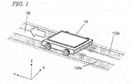
- FIG. 1 is a diagram schematically showing an example of a wireless power transmission system based on the electric field coupling method as conceived by the inventors.
- the wireless power transmission system shown in the figure may be a system which wirelessly transmits electric power to a transport robot (automated guided vehicle: AGV) 10 that is used in transporting articles in a factory, for example.
- AGV automated guided vehicle
- the transport robot 10 is an example of a vehicle according to the present disclosure.
- a pair of transmission electrodes 120a and 120b which are in plate shape, are disposed on the road surface (floor surface) 30.
- the transport robot 10 includes a pair of reception electrodes (not shown) opposing the pair of transmission electrodes 120a and 120b.
- the transport robot 10 receives AC power which has been transmitted from the transmission electrodes 120a and 120b.
- the received electric power is supplied to a load in the transport robot 10, e.g., a motor, a secondary battery, or a capacitor for electrical storage purposes. With this, the transport robot 10 may be driven or charged.
- FIG. 1 shows XYZ coordinates indicating the X, Y and Z directions which are orthogonal to one another.
- the following description will rely on XYZ coordinates as shown in the figures.
- the direction that the transmission electrodes 120a and 120b extend will be referred to as the Y direction; a direction which is perpendicular to the surface of the transmission electrodes 120a and 120b as the Z direction; and a direction which is perpendicular to the Y direction and the Z direction as the X direction.
- the orientation of any structure that is shown in a drawing of the present application is so set for ease of description, and it shall not limit the orientation in which an embodiment of the present disclosure may actually be employed.
- the particular shape and size with which the whole or a part of any structure may be presented in a drawing shall not limit its actual shape and size.
- FIG. 2 is a diagram showing a general construction for the wireless power transmission system shown in FIG. 1 .
- This wireless power transmission system includes a power transmitter 100 and a transport robot (vehicle) 10.
- the power transmitter 100 includes a pair of transmission electrodes 120a and 120b, and a power transmitting circuit 110 which supplies AC power to the transmission electrodes 120a and 120b.
- the power transmitting circuit 110 is, for example, an AC output circuit including an inverter circuit.
- the power transmitting circuit 110 converts DC power which is supplied from a DC power source not shown into AC power, and outputs it to the pair of transmission electrodes 120a and 120b .
- the transport robot 10 includes a power receiver 200 and a load 330.
- the power receiver 200 includes a pair of reception electrodes 220a and 220b and a power receiving circuit 210 which converts the AC power that is received by the reception electrodes 220a and 220b into electric power as desired by the load 330 (e.g., DC voltage of a predetermined voltage or AC power of a predetermined frequency) and supplies it to the load 330.
- the power receiving circuit 210 may include various circuits such as a rectifier circuit or a frequency conversion circuit.
- the load 330 may be any device that consumes or stores electric power, e.g., a motor, a capacitor for electrical storage purposes, or a secondary battery. Through electric field coupling (capacitive coupling) between the pair of transmission electrodes 120a and 120b and the pair of reception electrodes 220a and 220b, electric power is wirelessly transmitted while the two pairs are opposed to each other.
- the transport robot 10 is able to wirelessly receive electric power while moving along the transmission electrodes 120a and 120b . While the transmission electrodes 120a and 120b and the reception electrodes 220a and 220b remain in a closely opposed state, the transport robot 10 moves in a direction that the transmission electrodes 120a and 120b extend (i.e., the Y direction in FIG. 1 ). As a result, the transport robot 10 is able to move while allowing a means of electrical storage, e.g., a capacitor, to be charged.
- a means of electrical storage e.g., a capacitor
- the following problem may occur when a plurality of vehicles (e.g., transport robots) simultaneously move and are simultaneously charged in such a wireless power transmission system. While a first vehicle is being charged, if a second vehicle travels over the transmission electrodes 120a and 120b, part of the energy that has been sent out from the transmission electrodes 120a and 120b will be received by the second vehicle, thereby lowering the efficiency of power transmission to the first vehicle.
- a plurality of vehicles e.g., transport robots
- a vehicle is a vehicle to be driven by electric power which is wirelessly transmitted from a power transmitter having two transmission electrodes, the vehicle comprising:
- the vehicle includes a first control circuit which, while the vehicle is traveling near the two transmission electrodes, increases the impedance of the vehicle as viewed from the power transmitter in response to an instruction from the power transmitter that the electric power is not to be received.
- the vehicle may further comprise a second control circuit which acquires information on at least one of a status of electric power transmission from the power transmitter to the vehicle, location of the vehicle, and remaining power of the secondary battery, determines whether or not electric power from the power transmitter is to be received based on the information, and sends the instruction to the first control circuit when determining that the electric power is not to be received.
- a second control circuit which acquires information on at least one of a status of electric power transmission from the power transmitter to the vehicle, location of the vehicle, and remaining power of the secondary battery, determines whether or not electric power from the power transmitter is to be received based on the information, and sends the instruction to the first control circuit when determining that the electric power is not to be received.
- the vehicle in itself is able to determine whether electric power is to be received or not, and when necessary, increases the impedance of the vehicle as viewed from the power transmitter. As a result, even if the vehicle travels near the transmission electrodes, decrease in the efficiency of power transmission from the transmission electrodes to another vehicle is suppressed.
- the "status of electric power transmission from the power transmitter to the vehicle” may include, for example, information on a value of at least one of power, voltage and current in the power receiving circuit of the vehicle, or a change rate over time thereof.
- the second control circuit may send the instruction to the first control circuit when a value of at least one of power, voltage and current in the power receiving circuit, or a change rate over time thereof, exceeds a threshold value.
- the value of at least one of power, voltage and current in the power receiving circuit, or the change rate over time thereof is greater than the threshold value when the power transmitter is transmitting power to another vehicle distinct from the vehicle.
- the value of at least one of power, voltage and current in the power receiving circuit, or the change rate over time thereof is not greater than the threshold value when the power transmitter is not transmitting power to another vehicle distinct from the vehicle.
- the first control circuit may request the power transmitter for power transmission.
- the first control circuit may request the power transmitter for power transmission.
- the power transmitter may increase the transmission power.
- the present disclosure encompasses a wireless power transmission system (also referred to as a "vehicle system”) that includes a power transmitter, one or more vehicles, and a central controller which controls the power transmitter and the one or more vehicles.
- the central controller performs wireless communication between the power transmitter and the one or more vehicles, thereby controlling them.
- the vehicle may perform the aforementioned impedance control in response to an instruction from the central controller.
- the first control circuit may increase the impedance of the vehicle as viewed from the power transmitter.
- the central controller acquires information on at least one of a status of electric power transmission from the power transmitter to the vehicle, location of the vehicle, and remaining power of the secondary battery, determines whether or not the vehicle is to receive the electric power from the power transmitter based on the information, and when determining that the electric power from the power transmitter is not to be received from the vehicle, sends the instruction to the first control circuit.
- the central controller may acquire information on at least one of a status of electric power transmission, location of the vehicle, and remaining power of the secondary battery, via wireless communication, for example.
- a "vehicle” is not limited to a wheeled vehicle such as the aforementioned transport robot, but encompasses any movable object that is driven by electric power.
- vehicles may include an electric vehicle that includes an electric motor and one or more wheels.
- Such a vehicle may be an automated guided vehicle (AGV) such as the aforementioned transport robot, an electric vehicle (Electric Vehicle: EV), or an electric cart, for example.
- AGV automated guided vehicle
- EV Electric Vehicle
- the "vehicle” within the meaning of the present disclosure also encompasses any movable object that lacks wheels.
- bipedal robots, unmanned aerial vehicles (UAV, or so-called drones) such as multicopters, and manned electric aircraft are also examples of "vehicles”.
- the vehicle determines that electric power from the power transmitter is not to be received. More specifically, when a value of at least one of power, voltage and current in a power receiving circuit, or a change rate over time thereof, exceeds a threshold value, the vehicle increases the impedance of the vehicle as viewed from the power transmitter, so that electric power from the power transmitter will not be received. This suppresses decrease in the efficiency of power transmission to another vehicle.
- FIG. 3 is a diagram showing a construction for a power transmitter 100 and a transport robot (as one example of a vehicle) 10 in a wireless power transmission system according to an embodiment of the present disclosure.
- the power transmitter 100 includes a power transmitting circuit 110, a pair of transmission electrodes 120a and 120b, a transmission detector 190, and a power transmission control circuit 150.
- the external AC power source 20 supplies AC power to the power transmitting circuit 110.
- the power transmitting circuit 110 may include a converter circuit and an inverter circuit. The AC power which is supplied to the power transmitting circuit 110 is converted by the converter circuit into DC power. Thereafter, the DC power is converted by the inverter circuit into another form of AC power.
- the pair of transmission electrodes 120a and 120b are connected to the power transmitting circuit 110. The pair of transmission electrodes 120a and 120b wirelessly transmit the AC power which is output from the power transmitting circuit 110.
- the transmission detector 190 detects a power, voltage, current, or the like at a specific site in the power transmitting circuit 110. In the present embodiment, as one example, the transmission detector 190 detects a current which is output from the inverter circuit in the power transmitting circuit 110. The transmission detector 190 sends data representing the detected value thereof to the power transmission control circuit 150 . The power transmission control circuit 150 sends a command based on this information to the power transmitting circuit 110.
- the transport robot 10 includes a power receiving circuit 210, a pair of reception electrodes 220a and 220b, a reception detector 290, a power reception control circuit 250, an electric motor 330 (which may hereinafter be simply referred to as the "motor 330 "), a motor control circuit 340, a charge-discharge control circuit 350, and a secondary battery 320 (which may hereinafter be simply referred to as the "battery 320" ).
- the pair of reception electrodes 220a and 220b establish capacitive coupling with their respective counterparts in the pair of transmission electrodes 120a and 120b .
- the pair of reception electrodes 220a and 220b receive AC power from the pair of transmission electrodes 120a and 120b .
- the power receiving circuit 210 is connected to the pair of reception electrodes 220a and 220b .
- the power receiving circuit 210 may include a rectifier circuit, with which the power receiving circuit 210 converts the AC power which is received by the pair of reception electrodes 220a and 220b into DC power.
- the power receiving circuit 210 may convert the received AC power into another form of AC power.
- the power receiving circuit 210 supplies the converted electric power to the electric motor 330 and/or the battery 320, which drive the transport robot 10 . Charging and discharging of the battery 320 is controlled by the charge-discharge control circuit 350.
- the reception detector 290 detects power, voltage, current, or the like at a specific site in the power receiving circuit 210 (e.g., immediately after a rectifier circuit). In the present embodiment, as one example, the reception detector 290 detects a current which is output from the rectifier circuit in the power receiving circuit 210.
- the power receiving circuit 210 sends data representing the detected value thereof to the power reception control circuit 250.
- the power reception control circuit 250 sends a command based on this information to the power receiving circuit 210 and the motor control circuit 340.
- the motor control circuit 340 starts or stops the electric motor 350.
- the motor control circuit 340 may include a converter circuit or an inverter circuit.
- the motor control circuit 340 corresponds to a first control circuit, whereas the power reception control circuit 250 corresponds to a second control circuit.
- the power reception control circuit 250 acquires information on the status of electric power transmission from the power transmitter 100 to the vehicle 10 and remaining power of the battery 320, and based on this information, determines whether electric power from the power transmitter 100 is to be received or not. When determining that electric power is not to be received, the power reception control circuit 250 sends to the motor control circuit 340 an instruction that electric power is not to be received. Upon receiving this instruction, the motor control circuit 340 stops the motor 330, thereby increasing the impedance of the vehicle 10 as viewed from the power transmitter 100 .
- the power transmission control circuit 150 of the power transmitter 100 and the power reception control circuit 250 of the transport robot 10 are able to communicate with each other wirelessly.
- the transmission electrodes 120a and 120b may be indiscriminately expressed as "transmission electrodes 120".
- the reception electrodes 220a and 220b may be indiscriminately expressed as “reception electrodes 220”.
- a current/voltage/power as taken at a specific site in the power transmitting circuit 110 or the power receiving circuit 210 may simply be referred to as a "current/voltage/power in the power transmitting circuit 110 or the power receiving circuit 210".
- FIG. 4A is a diagram schematically showing change over time in the relative positioning of a transport robot 10a and transmission electrodes 120.
- Upward arrows schematically represent electric power which is supplied to the transport robot 10a. The number of upward arrows corresponds to the amount of received power. Downward blank arrows indicate lapse of time.
- the power transmitter 100 is constantly transmitting weak electric power from the transmission electrodes 120. The level of weak electric power is such that it does not affect the environment, but is also detectable by the circuitry on the reception side.
- the transport robot 10a When the traveling transport robot 10a begins to move over the transmission electrodes 120 as shown in the middle illustration, the transport robot 10a begins to receive the weak electric power from the transmission electrodes 120. At this time, since the transmitted power is weak, the power, voltage, and current that are output from the rectifier circuit in the power receiving circuit 210 of the transport robot 10a do not increase much from zero.
- the power reception control circuit 250 of the transport robot 10a determines that no other transport robot exists over the transmission electrodes 120 that is receiving power.
- the power reception control circuit 250 of the transport robot 10a determines whether or not there is need to receive power. "Need to receive power” exists when, for example, the remaining power in the battery 320 of the transport robot 10a is smaller than a predetermined value, etc.
- the power reception control circuit 250 requests the power transmission control circuit 150 of the power transmitter 100 to give full transmission.
- Full transmission means transmission of relatively large electric power, through which the transport robot is provided with the power that it needs.
- the power under full transmission is larger than the power under weak transmission.
- the power transmitting circuit 110 switches from weak transmission to full transmission.
- FIG. 4B is a diagram showing an example change over time of a current in the power receiving circuit 210 of the transport robot 10a.
- a case of utilizing a detected value of a current that flows in the power receiving circuit 210 will be described.
- a detected value of voltage or power in the power receiving circuit 210 may be utilized.
- the current to be detected in the power receiving circuit 210 is a DC current.
- the presence or absence of another transport robot may be determined based on change over time in the amplitude of the AC current.
- a current in the power receiving circuit 210 will be depicted as linear changes. In actuality, the current in the power receiving circuit 210 may undergo changes that represent a curve, due to noise or transient response.
- the transport robot 10a continues to receive weak electric power from the transmission electrodes 120.
- a current C 0 in the power receiving circuit 210 begins to increase from zero.
- the transport robot 10a moves along the transmission electrodes 120, the move causes a gradual increase in the area of overlap between the transmission electrodes 120 and the reception electrodes 220, thereby also increasing the detected current.
- the current C 0 in the power receiving circuit 210 has a value I weak which is governed by the status of the load and the transmission efficiency at that moment.
- the transport robot 10a does not request the power transmitter 100 for full transmission; therefore, as is indicated by a broken line in FIG. 4B , the current C 0 in the power receiving circuit 210 stays at the constant value I weak .
- the transport robot 10a requests the transmission electrodes 120 for full transmission.
- the output current C 1 from the power receiving circuit 210 increases from zero and reaches I weak .
- this transmission power will also be received by the transport robot 10a.
- the current C 1 in the power receiving circuit 210 of the transport robot 10a drastically increases to a value which is much higher than I weak .
- a threshold value e.g., a value which is equal to or greater than I weak
- the power reception control circuit 250 of the transport robot 10a may determine that no other transport robot exists over the transmission electrodes 120 that is receiving power. After making this determination, the power reception control circuit 250 of the transport robot 10a requests the power transmission control circuit 150 to begin full transmission.
- I full may be set to five times greater than I weak , or even more, for example.
- FIG. 4C is a diagram showing another example where a current in the power receiving circuit 210 of the transport robot 10a undergoes change over time. If a predetermined amount of time has elapsed before the change rate over time of a current C' 1 in the power receiving circuit 210 exceeds a threshold value (e.g., the change rate over time concerning an amount of increase of the current C 0 from zero), the power reception control circuit 250 of the transport robot 10a may determine that no other transport robot exists over the transmission electrodes 120 that is receiving power. After making this determination, the power reception control circuit 250 of the transport robot 10a requests the power transmission control circuit 150 to begin power transmission. Once the power transmitting circuit 110 of the power transmitter 100 begins full transmission, the current C' 1 in the power receiving circuit 210 drastically increases.
- a threshold value e.g., the change rate over time concerning an amount of increase of the current C 0 from zero
- the current C' 1 in the power receiving circuit 210 undergoes a proportional increase, until reaching a constant value I full .
- determining the presence or absence of another transport robot based on the change rate over time of a current allows a signal requesting the power transmission control circuit 150 to begin full transmission to be sent more quickly.
- the transport robot 10a After full transmission has begun, the transport robot 10a which is receiving power goes past the transmission electrodes 120. Then, the current in the power receiving circuit 210 begins to decrease from I full , until finally reaching zero. Similarly, the current in the power transmitting circuit 110 also begins to decrease. As a result of this, the power transmission control circuit 150 is able to determine that the transport robot 10a has passed. After making this determination, with a command from the power transmission control circuit 150, the power transmitting circuit 110 switches from full transmission to weak transmission. In another method, while the transport robot 10a is passing over the transmission electrodes 120, the power reception control circuit 250 of the transport robot 10a may send a command to the power transmission control circuit 150 to switch from full transmission to weak transmission.
- Suppressing supply of electric power to the transport robot 10a corresponds to decreasing the current in the power receiving circuit 210 of the transport robot 10a. This is equivalent to increasing the impedance of the transport robot 10a as viewed from the power transmitter 100.
- One possible method of controlling the impedance of the transport robot 10a as viewed from the power transmitter 100 may be a method of controlling driving of the electric motor 330 in the transport robot 10a (which will be referred to as the motor drive controlling method).
- FIG. 5A is a diagram schematically showing change over time in the relative positioning of two transport robots 10a and 10b , which perform control under the motor drive controlling method, and the transmission electrodes 120.
- another transport robot 10b that is receiving power exists over the transmission electrodes 120.
- the transport robot 10a travels over the transmission electrodes 120 as indicated in the middle illustration of FIG. 5A , the transport robot 10a receives electric power which is sent from the transmission electrodes 120. Since full transmission is being conducted, the current in the power receiving circuit 210 of the transport robot 10a drastically increases from zero. The current value and the change rate over time thereof are remarkably greater than those in the examples shown in FIG. 4B and FIG. 4C .
- the power reception control circuit 250 of the transport robot 10a may determine that another transport robot 10b exists over the transmission electrodes 120 that is receiving power. In that case, the power reception control circuit 250 of the transport robot 10a sends to the motor control circuit 340 a command to stop the electric motor 330. As is indicated in the lowermost illustration of FIG. 5A , with the command to stop the motor, the transport robot 10a makes a stop near the entry into the transmission electrodes 120. This makes it possible to suppress decrease in the efficiency of power transmission from the transmission electrodes 120 to another transport robot 10b.
- FIG. 5B is a diagram showing an example change over time of a current in the power receiving circuit 210 of the transport robot 10a , in the case where control under the motor drive controlling method is performed.
- a threshold value for the current in the power receiving circuit 210 is set to a value which is equal to or greater than I weak .
- a current C 0 in FIG. 5B depicts an example change over time in the current in the power receiving circuit 210 in the case where there is no need to receive power. This current corresponds the current C 0 shown in FIG. 4B , except for being represented in different scales therefrom as to time and current.
- a current C 2 in the power receiving circuit 210 undergoes a large increase as compared to the case where no other transport robot 10b exists.
- the power reception control circuit 250 of the transport robot 10a sends to the motor control circuit 340 a command to stop the electric motor 330.
- the geometric area in which the transmission electrodes 120 and the reception electrodes 220 of the transport robot 10a are opposed ceases to increase and remains constant at a level which is sufficiently small relative to the maximum possible area.
- the current C 2 in the power receiving circuit 210 maintains at a constant value.
- This constant value is sufficiently smaller than the I full value which pertains to full transmission, and thus is expected to make the influences on the transport robot 10b sufficiently small. Making the current in the power receiving circuit 210 of the transport robot 10a sufficiently small is equivalent to increasing the impedance of the transport robot 10a as viewed from the power transmitter 100.
- FIG. 5C is a diagram showing another example change over time of a current in the power receiving circuit 210 of the transport robot 10a in the case where control under the motor drive controlling method is performed.
- a change rate over time of the current C 0 existing before the current value in the power receiving circuit 210 reaches I weak is set as a threshold value.
- a command to stop the electric motor 330 is sent to the motor control circuit 340 of the transport robot 10a.
- a current C' 2 in the power receiving circuit 210 has a final value which is smaller than the value in the example of FIG. 5B .
- the power transmitter 100 switches from full transmission to weak transmission.
- the current in the power receiving circuit 210 of the transport robot 10a begins to decrease from the constant value.
- the motor control circuit 340 of the transport robot 10a sends a command to the electric motor 330 to start.
- the transport robot 10a begins to travel again. In this case, it is evident that no transport robot 10b that is receiving power exists over the transmission electrodes 120.
- the power reception control circuit 250 of the transport robot 10a sends a command to the power transmission control circuit 150 of the power transmitter 100 to switch from weak transmission to full transmission.
- a decrease in the current in the power receiving circuit 210 may be determined based on whether the current value in the power receiving circuit 210 or the change rate over time thereof has become lower than the threshold value or not. This threshold value may be different from the threshold value which is used in determining the presence or absence of another transport robot 10b over the transmission electrodes 120 that is receiving power.
- FIG. 6 is a flowchart showing an example of motor drive controlling for the transport robot 10a.
- the power reception control circuit 250 determines whether a predetermined amount of time has elapsed before the current value in the power receiving circuit 210 or the change rate over time thereof exceeds a threshold value (S101). If a predetermined amount of time has elapsed before the current value in the power receiving circuit 210 or the change rate over time thereof exceeds the threshold value, the power reception control circuit 250 determines whether there is need to receive power or not (S102). If there is need to receive power, the power reception control circuit 250 sends to the power transmission control circuit 150 a command to switch from weak transmission to full transmission (S103).
- the power reception control circuit 250 sends a command to the electric motor 330 to stop via the motor control circuit 340 (S104). Thereafter, the power reception control circuit 250 determines whether the current in the power receiving circuit 210 has begun to decrease or not (S105). If the current in the power receiving circuit 210 has begun to decrease, the power reception control circuit 250 sends a command to the electric motor 330 to start (S106). Thereafter, the power reception control circuit 250 determines whether there is need to receive power or not (S102).
- FIG. 7A is a diagram showing the construction of the power transmitter 100 and the transport robot 10 in a wireless power transmission system according to a variant of the present embodiment.
- the transport robot 10 includes a switch control circuit 255.
- the power receiving circuit 210 includes switches whose electrical connections can be turned ON or OFF.
- the switch control circuit 255 Upon receiving an instruction from the power reception control circuit 250, the switch control circuit 255 sends a command to turn ON or OFF the switch connections in the power receiving circuit 210.
- the power reception control circuit 250 and the switch control circuit 255 are illustrated as separate circuits in the present embodiment, a single circuit containing these circuits may be provided.
- the switch control circuit 255 corresponds to the first control circuit
- the power reception control circuit 250 corresponds to the second control circuit.
- FIG. 7B is a diagram schematically showing an exemplary arrangement of switch circuits 270.
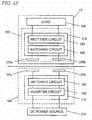
- the power receiving circuit 210 includes a matching circuit 280, a rectifier circuit 260, and a plurality of switch circuits 270.
- the switch circuits 270 are connected in at least one of the following places: between the reception electrodes 220 and the impedance matching circuit (hereinafter referred to as the "matching circuit") 280; between the matching circuit 280 and the rectifier circuit 260; between the rectifier circuit 260 and the charge-discharge control circuit 350; and between the charge-discharge control circuit 350 and the electric motor 330.
- the term "power receiving circuit” may allude to any circuitry that includes constituent elements between the reception electrodes 220 and the electric motor 330.
- FIG. 8A is a diagram schematically showing an example change over time in the relative positioning of two transport robots 10a and 10b and transmission electrodes 120, in the case where control under the power-receiving circuit controlling method is performed.
- a transport robot 10b that is receiving power exists over the transmission electrodes 120.
- the traveling transport robot 10a travels over the transmission electrodes 120, as is indicated in the middle illustration of FIG. 8A , the transport robot 10a begins to receive electric power from the transmission electrodes 120.
- the current in the power receiving circuit 210 of the transport robot 10a drastically increases from zero.
- the transport robot 10a may determine that another transport robot 10b that is receiving power exists over the transmission electrodes 120. At this time, the power reception control circuit 250 of the transport robot 10a sends to the power receiving circuit 210 a command to turn OFF the electrical connection of at least one switch, via the switch control circuit 255. Thus cuts the current path in the power receiving circuit 210, so that there is zero current in the power receiving circuit 210. As is indicated in the lowermost illustration of FIG. 8A , based on the command to the power receiving circuit 210, the transport robot 10a stops power reception. However, supply of power to its motor 330 can be continued.
- the transport robot 10a is able to continue traveling, while not affecting supply of power to the transport robot 10b.
- the power-receiving circuit controlling method is able to suppress decrease in the efficiency of power transmission from the transmission electrodes 120 to another transport robot 10b.
- FIG. 8B is a diagram showing an example change over time of a current in the power receiving circuit 210 of the transport robot 10a , in the case where control under the power-receiving circuit controlling method is performed.
- a threshold value for the current is set to a value which is equal to or greater than I weak .
- the current C 0 represents change over time of the current in the power receiving circuit 210 during weak transmission. This current corresponds to the current C 0 in the power receiving circuit 210 in FIG. 5B .
- the current C 3 in the power receiving circuit 210 greatly increases from zero, as compared to how it was during weak transmission.
- the switch control circuit 255 of the transport robot 10a sends to the power receiving circuit 210 a command to turn OFF the electrical connection of at least one switch, so that there is zero current in the power receiving circuit 210.
- There being zero current flowing in the power receiving circuit 210 is equivalent to the impedance of the transport robot 10a as viewed from the power transmitter 100 being increased to infinity.
- FIG. 8C is a diagram showing another example change over time of a current in the power receiving circuit 210 of the transport robot 10a in the case where control under the power-receiving circuit controlling method is performed.
- the change rate over time of the current C 0 during weak transmission, before the current value reaches I weak is set as a threshold value.
- the power reception control circuit 250 of the transport robot 10a sends to the power receiving circuit 210 a command to turn OFF electrical connection, via the switch control circuit 255.
- the current C' 3 in the power receiving circuit 210 becomes zero.
- the switch control circuit 255 of the transport robot 10a sends a command to turn ON electrical connection in the power receiving circuit 210.
- the aforementioned predetermined amount of time may be set to a period of time at which the transport robot 10b will presumably have gone past the transmission electrodes 120 so that the power transmitter 100 will have returned to weak transmission from full transmission.
- the transport robot 10a traveling over the transmission electrodes 120 again begins to receive electric power from the transmission electrodes 120.
- the power reception control circuit 250 of the transport robot 10a again determines the presence or absence of any transport robot 10b over the transmission electrodes 120 that is receiving power.
- FIG. 9 is a flowchart showing an example of power-receiving circuit controlling in the transport robot 10a. Instead of Steps S104, S105 and S106 in the flowchart of FIG. 6 , Steps S107, S108 and S109 are executed. If the current value in the power receiving circuit 210 or the change rate over time thereof is higher than the threshold value, the power reception control circuit 250 sends to the power receiving circuit 210 a command to turn OFF electrical connection via the switch control circuit 255 (S107). Thereafter, the power reception control circuit 250 determines whether the predetermined amount of time has elapsed (S108).
- the power reception control circuit 250 sends to the power receiving circuit 210 a command to turn ON electrical connection, via the switch control circuit 255 (S109). Thereafter, the power reception control circuit 250 again determines whether or not the current value in the power receiving circuit 210 or the change rate over time thereof is equal to or less than the threshold value (S101).
- the transport robot 10a stops near the entry of the transmission electrodes 120 ( FIG. 5A ).
- the transport robot 10a travels over the transmission electrodes 120 without receiving power ( FIG. 8A ). In other words, under power-receiving circuit controlling, travel of the transport robot 10a does not incur loss of time.
- the current in the power receiving circuit 210 of the transport robot 10a has a constant value which is sufficiently smaller than I full ( FIG. 5B or FIG. 5C ).
- the current in the power receiving circuit 210 of the transport robot 10a becomes zero ( FIG. 8B or FIG. 8C ). In other words, under the power-receiving circuit controlling method, the transport robot 10a never affects another transport robot 10b over the transmission electrodes 120 that is receiving power.
- the motor drive controlling method and the power-receiving circuit controlling method described above may be used in combination.
- FIG. 10 is a flowchart showing another example of the motor drive controlling method in the transport robot 10a. Instead of Steps S107 to S109 in the flowchart of FIG. 9 , Steps S110 to S112 are executed. If the current value in the power receiving circuit 210 or the change rate over time thereof exceeds a threshold value, the power reception control circuit 250 sends a command to the electric motor 330 to stop ( S110 ). Thereafter, the power reception control circuit 250 determines whether a predetermined amount of time has elapsed or not ( S111 ). If the predetermined amount of time has elapsed, the power reception control circuit 250 sends to the electric motor 330 a command to start, via the motor control circuit 340 ( S112 ).
- the power reception control circuit 250 again determines whether or not the current value in the power receiving circuit 210 or the change rate over time thereof is equal to or less than the threshold value ( S101 ).
- the predetermined amount of time a period of time which is obtained by dividing the length of the transmission electrodes 120 by the velocity of travel of the transport robot 10b may be used. In this case, after the motor in the transport robot 10a is started ( S112 ), there will be no other transport robot 10b over the transmission electrodes 120 that is receiving power.
- the power reception control circuit 250 may determine whether there is need to receive power or not next ( S102 ).
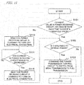
- FIG. 11 is a flowchart showing another example of the power-receiving circuit controlling method in the transport robot 10a. Instead of Steps S104 to S106 in FIG. 6 , Steps S113 to S115 are executed. If the current value in the power receiving circuit 210 or the change rate over time thereof exceeds a threshold value, the power reception control circuit 250 sends to the power receiving circuit 210 a command to increase impedance ( S113 ). At this time, the current in the power receiving circuit 210 is sufficiently small than I full . However, let it be assumed that the current in the power receiving circuit 210 never reaches zero, unlike in the aforementioned power-receiving circuit controlling method.
- the power reception control circuit 250 determines whether the current in the power receiving circuit 210 has begun to decrease or not ( S114 ). If the current in the power receiving circuit 210 has begun to decrease, the power reception control circuit 250 sends to the power receiving circuit 210 a command to decrease impedance, via the switch control circuit 255 ( S115 ). Thereafter, the power reception control circuit 250 determines whether there is need to receive power or not ( S102 ). Adjustment of the impedance of the power receiving circuit 210 to be higher or lower may be achieved by, for example, changing the value of at least one of the resistance, inductance, and capacitance of the power receiving circuit 210.
- Patent Document 1 a voltage monitoring section in the power transmitter monitors voltage. When the voltage exceeds a predetermined threshold value, a power transmission stop section in the power transmitter stops power transmission to the power receiver.
- the power reception control circuit 250 of the transport robot 10a determines the presence or absence of another transport robot 10b over the transmission electrodes 120. If another transport robots 10b exists over the transmission electrodes 120 , the transport robot 10a suppress power reception from the transmission electrodes 120. That is, in the present embodiment, power transmission can be controlled on the reception side. Such control of power transmission on the reception side is applicable not only to a system including two vehicles, but also to a system including three or more vehicles.
- the power reception control circuit 250 of the transport robot 10a requests the power transmission control circuit 150 to begin full transmission.
- a weak current which is much smaller than I weak may flow in the power receiving circuit 210.
- the power reception control circuit 250 of the transport robot 10a may erroneously request the power transmission control circuit 150 to begin power transmission.
- a threshold value (second threshold value) to be satisfied in making a request for power transmission may be introduced.
- the second threshold value may be set to a smaller value than the first threshold value. For example, after the lapse of a predetermined amount of time, the power reception control circuit 250 of the transport robot 10a may request the power transmission control circuit 150 to begin power transmission only if the current value or the change rate over time thereof has exceeded the second threshold value, while not exceeding the first threshold value.
- the power reception control circuit 250 of the transport robot 10a can determine that the transport robot 10a itself is not traveling over the transmission electrodes 120. In that case, the power reception control circuit 250 of the transport robot 10a may not request the power transmission control circuit 150 to begin power transmission.
- the second threshold value When the current value is relied upon, the second threshold value may be I weak , or a value which is slightly smaller than that, for example.
- the second threshold value When the change rate over time of current is relied upon, the second threshold value may be a change rate over time of the amount of increase in the current C 0 from zero, or a value which is slightly smaller than that, for example.
- the power reception control circuit 250 requests the power transmitter 100 for full transmission, through a determination based on change in the current or power flowing in the power receiving circuit 210 of the transport robot 10a.
- the power transmission control circuit 150 may determine arrival of the transport robot 10a over the transmission electrodes 120 based on change in the current or power flowing in the power transmitting circuit 110.
- the power transmitter 100 may request the transport robot 10a to decide whether or not to conduct full transmission.
- the power reception control circuit 250 of the transport robot 10a may request the power transmitter 100 for full transmission.
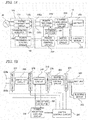
- FIG. 12 is block diagram generally showing a construction involved in the power transmission in the wireless power transmission system according to the present embodiment.
- the power transmitter 100 includes an inverter circuit 160 which converts DC power that is supplied from an external DC power source 310 into AC power, two transmission electrodes 120a and 120b which transmit the AC power, and a matching circuit 180 which is connected between the inverter circuit 160 and the transmission electrodes 120a and 120b.
- the "DC power source 310" also encompasses a power source that results from convertinq externally-supplied AC power into DC power with a converter circuit.
- the inverter circuit 160 are electrically connected to the first and second transmission electrodes 120a and 120b via the matching circuit 180, and outputs AC power to the first and second transmission electrodes 120a and 120b.
- the transport robot 10 includes a power receiver 200 and a load 330.
- the power receiver 200 includes two reception electrodes 220a and 220b which establish capacitive coupling with the two transmission electrodes 120a and 120b to receive electric power, a matching circuit 280 connected to the two reception electrodes 220a and 220b, and a rectifier circuit 260 which is connected to the matching circuit 280 and converts the received AC power into DC power and outputs it.
- the first reception electrode 220a When opposed to the first transmission electrode 120a, the first reception electrode 220a establish capacitive coupling with the first transmission electrode 120a.
- the second reception electrode 220b establish capacitive coupling with the second transmission electrodes. Via these two sites of capacitive coupling, AC power is contactlessly transmitted from the power transmitter 100 to the power receiver 200.
- the respective sizes of the housing of the transport robot 10 according to the present embodiment, the transmission electrodes 120a and 120b, and the reception electrodes 220a and 220b may be set to the following sizes, for example.
- the length (i.e., the size along the Y direction) of each of the transmission electrodes 120a and 120b may be set in a range from 50 cm to 20 m, for example.
- the width (i.e., the size along the X direction) of each of the transmission electrodes 120a and 120b may be set in a range from 5 cm to 2 m, for example.
- the sizes along the traveling direction and the lateral direction of the housing of the transport robot 10 may be set in a range from 20 cm to 5 m, for example.
- each reception electrode 220a may be set in a range from 5 cm to 2 m, for example.
- the width (i.e., the size along the lateral direction) of each reception electrode 220a may be set in a range from 2 cm to 2 m, for example.
- these numerical ranges are not limiting.
- the load 330 may include an electric motor for driving purposes and a capacitor for electrical storage purposes, for example, and may be driven or charged by DC power which is output from the power receiving circuit 210.
- the electric motor may be any type of motor, such as a DC motor, a permanent magnet synchronous motor, an induction motor, a stepping motor, or a reluctance motor.
- the motor rotates the wheels of the transport robot 10 via shafts, gears, and the like, thus causing the transport robot 10 to move.
- the power receiving circuit 210 may include various circuits, e.g., a rectifier circuit(s), an inverter circuit(s), and/or an inverter control circuit(s).
- the capacitor may be a high-capacitance and low-resistance capacitor, such as an electric double layer capacitor or a lithium-ion capacitor.
- a capacitor as a means of electrical storage will allow for more rapid charging than when a battery (secondary battery) is used.
- a secondary battery e.g., a lithium-ion battery
- the motor is driven with the electric power that is stored in the capacitor or secondary battery, whereby the transport robot 10 moves.
- the transport robot 10 As the transport robot 10 moves, the amount of stored electricity (charge amount) in the capacitor or secondary battery will decrease. Therefore, recharging will be required in order to continue the movement. Therefore, when the charge amount falls below a predetermined threshold value during movement, the transport robot 10 will perform charging from the power transmitter 100.
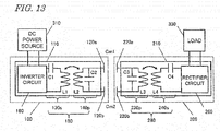
- FIG. 13 is a circuit diagram showing a more detailed exemplary construction for the wireless power transmission system.
- the matching circuit 180 of the power transmitter 100 includes a series resonant circuit 130s which is connected to the power transmitting circuit 110, and a parallel resonant circuit 140p which is connected to the transmission electrodes 120a and 120b and establishes inductive coupling with the series resonant circuit 130s.
- the matching circuit 180 has the function of matching the impedance of the inverter circuit 160 with the impedance of the transmission electrodes 120a and 120b.
- the series resonant circuit 130s of the power transmitter 100 includes a first coil L1 and a first capacitor C1 being connected in series.
- the parallel resonant circuit 140p of the power transmitter 100 includes a second coil L2 and a second capacitor C2 being connected in parallel.
- the first coil L1 and the second coil L2 constitute a transformer whose coupling is based on a predetermined coupling coefficient.
- the turns ratio between the first coil L1 and the second coil L2 is set to a value that realizes a desired transformation ratio (a step-up ratio or a step-down ratio).
- the matching circuit 280 of the power receiver 200 includes a parallel resonant circuit 230p which is connected to the reception electrodes 220a and 220b and a series resonant circuit 240s which is connected to the rectifier circuit 260 and establishes inductive coupling with the parallel resonant circuit 230p.
- the matching circuit 280 has the function of matching the impedance of the reception electrodes 220a and 220b with the impedance of the power receiving circuit 210.
- the parallel resonant circuit 230p includes a third coil L3 and a third capacitor C3 being connected in parallel.
- the series resonant circuit 240s of the power receiver 200 includes a fourth coil L4 and a fourth capacitor C4 being connected in series.
- the third coil L3 and the fourth coil L4 constitute a transformer whose coupling is based on a predetermined coupling coefficient.
- the turns ratio between the third coil L3 and the fourth coil L4 is set to a value that realizes a desired transformation ratio.
- the construction of the matching circuits 180 and 280 is not limited to what is shown in FIG. 13 .
- a parallel resonant circuit may be provided instead of each of the series resonant circuits 130s and 240s.
- a series resonant circuit may be provided instead of each of the parallel resonant circuits 140p and 230p.
- one or both of the matching circuits 180 and 280 may be omitted.
- the inverter circuit 160 and the transmission electrodes 120a and 120b are directly connected.
- the rectifier circuit 260 and the reception electrodes 220a and 220b are directly connected.
- a construction where the matching circuit 180 is provided also qualifies as a construction in which the inverter circuit 160 and the transmission electrodes 120a and 120b are electrically connected.
- a construction where the matching circuit 280 is provided also qualifies as a construction in which the rectifier circuit 260 and the reception electrodes 220a and 220b are electrically connected.
- FIG. 14A is a diagram schematically showing an exemplary construction for the inverter circuit 160.
- the inverter circuit 160 includes a full-bridge inverter circuit that contain four switching elements (e.g., transistors such as IGBTs or MOSFETs) and the power transmission control circuit 150.
- the power transmission control circuit 150 includes a gate driver which outputs a control signal to control the ON (conducting) or OFF (nonconducting) state of each switching element and a processor which causes the gate driver to output a control signal, e.g., a microcontroller.
- the inverter circuit 160 may include modulation/demodulation circuitry for communication purposes and various sensors for measuring voltage, current, etc. In the case where modulation/demodulation circuitry for communication purposes is included, data may be superposed onto the AC power so as to be sent to the power receiver 200.
- a weak AC signal e.g., a pulse signal
- transmission of a weak AC signal is also encompassed under the notion of "power transmission”.
- a weak AC signal is also encompassed under the notion of "AC power”.
- FIG. 14B is a diagram schematically showing an exemplary construction for the rectifier circuit 260.
- the power receiving circuit 210 is a full-wave rectifier circuit including a diode bridge and a smoothing capacitor.
- the rectifier circuit 260 may have any other rectifier construction.
- various circuits may also be included, such as constant voltage/constant current control circuitry, and/or modulation/demodulation circuitry for communication purposes.
- the rectifier circuit 260 converts the received AC energy into DC energy which is available for use by the load 330.
- Various sensors for measuring the voltage and current, etc., being output from the series resonant circuit 240s may also be included in the rectifier circuit 260.
- Each coil in the resonant circuits 130s, 140p, 230p and 240s may be, for example, a planar coil or a laminated coil that is formed on a circuit board, or a wound coil of a copper wire, a litz wire, a twisted wire, or the like.
- Each capacitor in the resonant circuits 130s, 140p, 230p and 240s may be any type of capacitor having a chip shape or a lead shape, for example. It may also be possible to allow the capacitance between two wiring lines, with air interposed therebetween, to function as a capacitor. The self-resonance property of each coil may also be utilized to replace any such capacitor.
- the DC power source 310 may be any kind of power source, e.g., a mains supply, a primary battery, a secondary battery, a photovoltaic cell, a fuel cell, a USB (Universal Serial Bus) power source, a high-capacitance capacitor (e.g., an electric double layer capacitor), a voltage converter that is connected to a mains supply, or the like.
- a mains supply e.g., a mains supply, a primary battery, a secondary battery, a photovoltaic cell, a fuel cell, a USB (Universal Serial Bus) power source, a high-capacitance capacitor (e.g., an electric double layer capacitor), a voltage converter that is connected to a mains supply, or the like.
- a mains supply e.g., a mains supply, a primary battery, a secondary battery, a photovoltaic cell, a fuel cell, a USB (Universal Serial Bus) power source, a high-capacit
- the resonant frequency f0 of the resonant circuits 130s, 140p, 230p and 240s is typically set equal to the transmission frequency f during power transmission.
- the resonant frequency f0 of each of the resonant circuits 130s, 140p, 230p and 240s may not be exactly equal to the transmission frequency f.
- Each resonant frequency f0 may be set to a value in a range from about 50% to about 150% of the transmission frequency f, for example.
- the power transmission frequency f may be set to e.g. 50Hz to 300 GHz, more preferably 20 kHz to 10 GHz, still more preferably 20 kHz to 20 MHz, and further more preferably 20 kHz to 7 MHz.
- an air gap exists between the transmission electrodes 120a and 120b and the reception electrodes 220a and 220b, with a relatively long distance therebetween (e.g., about 10 mm). Therefore, the capacitances Cm1 and Cm2 between these pairs of electrodes are very small, while the impedances of the transmission electrodes 120a and 120b and the reception electrodes 220a and 220b are very high (e.g., on the order of several k ⁇ ). On the other hand, the impedances of the power transmitting circuit 110 and the power receiving circuit 210 are as low as several ⁇ , for example.
- the parallel resonant circuits 140p and 230p are disposed closer to the transmission electrodes 120a, 120b and the reception electrodes 220a, 220b , respectively, whereas the series resonant circuits 130s and 240s are disposed closer to the power transmitting circuit 110 and the power receiving circuit 210, respectively.
- impedance matching can be easily attained.
- a series resonant circuit has zero (0) impedance during resonance, and therefore allows for matching with low impedance.
- a parallel resonant circuit has infinite impedance during resonance, and therefore allows for matching with high impedance.
- impedance matching can be easily achieved by disposing a series resonant circuit on the power source side, which is low in impedance, and a parallel resonant circuit on the electrode side, which is high in impedance.
- impedance matching in the power receiver 200 can be suitably achieved by disposing a parallel resonant circuit on the electrode side and a series resonant circuit on the load side.
- the impedances of the electrodes will be lowered, so that the aforementioned asymmetric resonant circuit construction is unnecessary.
- the matching circuits 180 and 280 may themselves be omitted.
- the determination as to whether a vehicle is to receive power or not is made by an external apparatus, which is distinct from the vehicle.
- the external apparatus notifies the vehicle of the result of determination. Upon receiving this notice, the vehicle alters its own impedance.
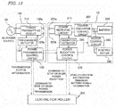
- FIG. 15 is a block diagram showing the construction of a wireless power transmission system according to the present embodiment.
- This wireless power transmission system includes at least one power transmitter 100, at least one vehicle 10, and a central controller 300 which manages traveling operations of the vehicle 10.
- the central controller 300 controls the power transmitter 100 and the at least one vehicle 10.
- the central controller 300 is connected, in a wireless or wired manner, to the power transmission control circuit 150 of the power transmitter 100 and the power reception control circuit 250 of the vehicle 10.
- the central controller 300 may be implemented as a computer having a control circuit such as a CPU and a storage device such as a memory, for example. As the control circuit executes a computer program which is stored in the storage device, the operation described may be achieved.
- the central controller 300 sends a command to stop or begin power transmission.
- the power transmission control circuit 150 sends information concerning the status of electric power transmission, e.g., a value of at least one of power, voltage and current in the power transmitting circuit 110, to the central controller 300. Transmission of this information from the power transmitter 100 to the central controller 300 may be performed every predetermined period of time, for example.
- the central controller 300 sends to the power reception control circuit 250 a command to begin or stop power reception.
- the power reception control circuit 250 sends information representing the location of the vehicle 10 and information representing the remaining power in the battery 320 to the central controller 300. Transmission of this information from the power receiver 10 to the central controller 300 may be performed every predetermined period of time, for example.
- the power transmitter 100 and the vehicle 10 shown in FIG. 15 are similar in construction to those shown in FIG. 3 .
- the vehicle 10 may have a construction as shown in FIG. 7A .
- the central controller 300 determines the timing to begin or stop power reception in the vehicle 10.
- the central controller 300 determines whether the vehicle 10 is to receive power or not, on basis of the above information.
- the central controller 300 sends a command to begin power reception or a command to stop power reception to the power reception control circuit 250.
- the power reception control circuit 250 of the vehicle 10 adjusts its own impedance.
- FIG. 16 is a flowchart showing an operation of the vehicle 10 according to the present embodiment.
- the power reception control circuit 250 of the vehicle 10 executes the following operation.
- the motor control circuit 340 increases the impedance of the vehicle 10 as viewed from the power transmitter 100 by stopping the motor 330.
- the power reception control circuit 250 may introduce an increased impedance through control of a switch(es), resistance, capacitance, or inductance in the power receiving circuit 210.
- the power reception control circuit 250 and the motor control circuit 340 together function as the "first control circuit".
- the central controller 300 may make a determination to begin or stop power reception based on the following prerequisites, for example.
- the central controller 300 makes a determination to begin or stop power reception based on any one of the following Criteria 1 to 3, for example.
- Criterion 1 first come, first served
- the vehicle that was the first to exist over the transmission electrodes is given priority, and a command to "stop power reception" is sent to a later-approaching vehicle.
- the later-approaching vehicle is given priority, and a command to "stop power reception" is sent to the vehicle that was the first to exist over the transmission electrodes.
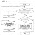
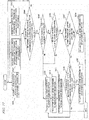
- FIG. 17 is a flowchart showing an exemplary operation of the central controller 300. It is assumed herein that, as shown in FIG. 5A , two vehicles 10a and 10b are vying to receive power from the pair of transmission electrodes 120. The vehicle 10b that was the first to exist over the transmission electrodes will be referred to as "the first vehicle 10b", whereas the vehicle that later approached the transmission electrodes will be referred to as "the latter vehicle 10a". In this example, the central controller 300 performs the following operation.
- the pair of transmission electrodes 120 are installed on the ground in the above embodiments, the pair of transmission electrodes 120 may instead be installed on a lateral surface, e.g., a wall, or an overhead surface, e.g., a ceiling. Depending on the place and orientation in which the transmission electrodes 120 are installed, the arrangement and orientation of the reception electrodes 220 of the vehicle 10 are to be determined.
- FIG. 18A is a diagram showing an example where the transmission electrodes 120 are installed on a lateral surface e.g., a wall. In this example, the reception electrodes 220 are provided on a lateral side of the vehicle 10.
- FIG. 18B is a diagram showing an example where the transmission electrodes 120 are installed on a ceiling. In this example, the reception electrodes 220 are provided on the top of the vehicle 10. As demonstrated by these examples, there may be a variety of arrangements for the transmission electrodes 110 and the reception electrodes 210.
- a wireless power transmission system may be used as a system of transportation for articles within a factory, as mentioned above.
- the transport robot 10 functions as a cart having a bed on which to carry articles, and autonomously move in the factory to transport articles to necessary places.
- the wireless power transmission system and the vehicle according to the present disclosure are also usable for various other purposes.
- the vehicle may be any other industrial machine, a service robot, an electric vehicle, a multicopter (drone), or the like.
- the wireless power transmission system may be used in shops, hospitals, households, roads, runways, or other places, for example.
- the present disclosure encompasses vehicles and wireless power transmission systems as recited in the following Items.
- the technique according to the present disclosure is applicable to any device that is driven with electric power.
- it is applicable to transport robots or electric vehicles, such as automated guided vehicles (AGV) that are used in a factory.
- AGV automated guided vehicles
Landscapes
- Engineering & Computer Science (AREA)
- Power Engineering (AREA)
- Transportation (AREA)
- Mechanical Engineering (AREA)
- Life Sciences & Earth Sciences (AREA)
- Sustainable Development (AREA)
- Sustainable Energy (AREA)
- Computer Networks & Wireless Communication (AREA)
- Charge And Discharge Circuits For Batteries Or The Like (AREA)
- Electric Propulsion And Braking For Vehicles (AREA)
- Current-Collector Devices For Electrically Propelled Vehicles (AREA)
Abstract
Description
- The present disclosure relates to a vehicle that is driven by electric power which is wirelessly transmitted thereto, and relates also to a wireless power transmission system.
- In recent years, wireless power transmission techniques for wirelessly (contactlessly) transmitting electric power to devices that are capable of moving or being moved, e.g., mobile phones and electric vehicles, have been being developed. Wireless power transmission techniques include methods based on electromagnetic induction and methods based on electric field coupling. Among these, a wireless power transmission system based on the electric field coupling method is such that, while a pair of transmission electrodes and a pair of reception electrodes are opposed to each other, AC power is wirelessly transmitted from the pair of transmission electrodes to the pair of reception electrodes. A wireless power transmission system based on such an electric field coupling method may be used for the purpose of transmitting electric power to a load (e.g., a motor or a battery in a vehicle such as a mobile robot) from a pair of transmission electrodes that are provided on the road surface (or on the floor surface). International Publication No.
2015/037526 (hereinafter "Patent Document 1") discloses an example of a wireless power transmission system based on such an electric field coupling method. - In a wireless power transmission system based on the electric field coupling method, when a vehicle travels near a pair of transmission electrodes that are provided on the road surface, etc., electric power is transmitted from the transmission electrodes to the vehicle. However, if the power transmitter has already been transmitting electric power to another ("first") vehicle, the efficiency of power transmission to this first vehicle will decrease as a second vehicle travels near the transmission electrode.
- The present disclosure provides a novel technique which, even if a second vehicle happens to travel near transmission electrodes, does not allow much decrease in the efficiency of power transmission to a first vehicle which has already been being charged.
- In order to solve the above problems, a vehicle according to one implementation of the present disclosure, to be driven by electric power which is wirelessly transmitted from a power transmitter having two transmission electrodes, comprises:
- two reception electrodes to receive AC power from the two transmission electrodes through capacitive coupling respectively with the two transmission electrodes;
- a power receiving circuit which is connected to the two reception electrodes to convert AC power received by the two reception electrodes into DC power or another form of AC power, and supply the DC power or other form of AC power to an electric motor which drives the vehicle or to a secondary battery which stores electric power for driving the vehicle; and
- a first control circuit which, while the vehicle is moving with the two reception electrodes being opposed to the two transmission electrodes, increases an impedance of the vehicle as viewed from the power transmitter in response to an instruction that the electric power from the power transmitter is not to be received.
- General or specific aspects of the present disclosure may be implemented using a system, a method, an integrated circuit, a computer program, or a storage medium, or any combination of a system, an apparatus, a method, an integrated circuit, a computer program, and/or a storage medium.
- With the technique according to the present disclosure, it is possible to suppress decrease in the efficiency of power transmission from the transmission electrodes to a first vehicle even if a second vehicle happens to travel near the transmission electrodes.
- Other features, elements, processes, steps, characteristics and advantages of the present invention will become more apparent from the following detailed description of preferred embodiments of the present invention with reference to the attached drawings.
-
-
FIG. 1 is a diagram schematically showing an example of a wireless power transmission system based on the electric field coupling method, as conceived by the inventors. -
FIG. 2 is a diagram showing a general construction for the wireless power transmission system shown inFIG. 1 . -
FIG. 3 is a diagram showing a construction for apower transmitter 100 and a transport robot (vehicle) 10 in a wireless power transmission system according to an embodiment of the present disclosure. -
FIG. 4A is a diagram schematically showing change over time in the relative positioning of atransport robot 10a andtransmission electrodes 120. -
FIG. 4B is a diagram showing an example where a current in a power receivingcircuit 210 of atransport robot 10a undergoes change over time. -
FIG. 4C is a diagram showing another example where a current in a power receivingcircuit 210 of atransport robot 10a undergoes change over time. -
FIG. 5A is a diagram schematically showing change over time in the relative positioning of twotransport robots transmission electrodes 120, under motor drive controlling. -
FIG. 5B is a diagram showing an example where a current in a power receivingcircuit 210 of atransport robot 10a undergoes change over time, under motor drive controlling. -
FIG. 5C is a diagram showing another example where a current in a power receivingcircuit 210 of atransport robot 10a undergoes change over time, under motor drive controlling. -
FIG. 6 is a flowchart showing an example of motor drive controlling for thetransport robot 10a. -
FIG. 7A is another diagram showing the construction of apower transmitter 100 and atransport robot 10 in a wireless power transmission system according to an embodiment of the present disclosure. -
FIG. 7B is a diagram schematically showing the location ofswitch circuits 270, each including a switch to turn ON or OFF electrical connection, in atransport robot 10a. -
FIG. 8A is a diagram schematically showing change over time in the relative positioning of twotransport robots transmission electrodes 120, under power-receiving circuit controlling. -
FIG. 8B is a diagram showing an example where a current in a power receivingcircuit 210 of atransport robot 10a undergoes change over time, under power-receiving circuit controlling. -
FIG. 8C is a diagram showing another where a current in a power receivingcircuit 210 of atransport robot 10a undergoes change over time, under power-receiving circuit controlling. -
FIG. 9 is a flowchart showing an example of power-receiving circuit controlling in thetransport robot 10a. -
FIG. 10 is a flowchart showing another example of motor drive controlling in thetransport robot 10a. -
FIG. 11 is a flowchart showing another example of power-receiving circuit controlling in thetransport robot 10a. -
FIG. 12 is block diagram generally showing a construction involved in the power transmission in a wireless power transmission system according to the present embodiment. -
FIG. 13 is a circuit diagram showing a more detailed exemplary construction for the wireless power transmission system. -
FIG. 14A is a diagram schematically showing an exemplary construction for aninverter circuit 160. -
FIG. 14B is a diagram schematically showing an exemplary construction for arectifier circuit 260. -
FIG. 15 is a block diagram showing the construction of a wireless power transmission system according toEmbodiment 2. -
FIG. 16 is a flowchart showing an operation of avehicle 10 according toEmbodiment 2. -
FIG. 17 is a flowchart showing an exemplary operation of acentral controller 300. -
FIG. 18A is a diagram showing an example wheretransmission electrodes 120 are installed on a lateral surface e.g., a wall. -
FIG. 18B is a diagram showing an example wheretransmission electrodes 120 are installed on a ceiling. - Prior to describing embodiments of the present disclosure, findings providing the basis of the present disclosure will be described.
-
FIG. 1 is a diagram schematically showing an example of a wireless power transmission system based on the electric field coupling method as conceived by the inventors. The wireless power transmission system shown in the figure may be a system which wirelessly transmits electric power to a transport robot (automated guided vehicle: AGV) 10 that is used in transporting articles in a factory, for example. Thetransport robot 10 is an example of a vehicle according to the present disclosure. In this system, a pair oftransmission electrodes transport robot 10 includes a pair of reception electrodes (not shown) opposing the pair oftransmission electrodes transport robot 10 receives AC power which has been transmitted from thetransmission electrodes transport robot 10, e.g., a motor, a secondary battery, or a capacitor for electrical storage purposes. With this, thetransport robot 10 may be driven or charged. -
FIG. 1 shows XYZ coordinates indicating the X, Y and Z directions which are orthogonal to one another. The following description will rely on XYZ coordinates as shown in the figures. The direction that thetransmission electrodes transmission electrodes -
FIG. 2 is a diagram showing a general construction for the wireless power transmission system shown inFIG. 1 . This wireless power transmission system includes apower transmitter 100 and a transport robot (vehicle) 10. Thepower transmitter 100 includes a pair oftransmission electrodes power transmitting circuit 110 which supplies AC power to thetransmission electrodes power transmitting circuit 110 is, for example, an AC output circuit including an inverter circuit. Thepower transmitting circuit 110 converts DC power which is supplied from a DC power source not shown into AC power, and outputs it to the pair oftransmission electrodes - The
transport robot 10 includes apower receiver 200 and aload 330. Thepower receiver 200 includes a pair ofreception electrodes power receiving circuit 210 which converts the AC power that is received by thereception electrodes load 330. Thepower receiving circuit 210 may include various circuits such as a rectifier circuit or a frequency conversion circuit. Theload 330 may be any device that consumes or stores electric power, e.g., a motor, a capacitor for electrical storage purposes, or a secondary battery. Through electric field coupling (capacitive coupling) between the pair oftransmission electrodes reception electrodes - With such a wireless power transmission system, the
transport robot 10 is able to wirelessly receive electric power while moving along thetransmission electrodes transmission electrodes reception electrodes transport robot 10 moves in a direction that thetransmission electrodes FIG. 1 ). As a result, thetransport robot 10 is able to move while allowing a means of electrical storage, e.g., a capacitor, to be charged. - However, the following problem may occur when a plurality of vehicles (e.g., transport robots) simultaneously move and are simultaneously charged in such a wireless power transmission system. While a first vehicle is being charged, if a second vehicle travels over the
transmission electrodes transmission electrodes - The inventors have found the aforementioned problem, and sought for constructions for solving this problem. Consequently, the inventors have succeeded in solving the above problem based on embodiments of the present disclosure as will be described below.
- A vehicle according to one implementation of the present disclosure is a vehicle to be driven by electric power which is wirelessly transmitted from a power transmitter having two transmission electrodes, the vehicle comprising:
- two reception electrodes to receive AC power from the two transmission electrodes through capacitive coupling respectively with the two transmission electrodes;
- a power receiving circuit which is connected to the two reception electrodes to convert AC power received by the two reception electrodes into DC power or another form of AC power, and supply the DC power or other form of AC power to an electric motor which drives the vehicle or to a secondary battery which stores electric power for driving the vehicle; and
- a first control circuit which, while the vehicle is moving with the two reception electrodes being opposed to the two transmission electrodes, increases an impedance of the vehicle as viewed from the power transmitter in response to an instruction that the electric power from the power transmitter is not to be received.
- In the above implementation, the vehicle includes a first control circuit which, while the vehicle is traveling near the two transmission electrodes, increases the impedance of the vehicle as viewed from the power transmitter in response to an instruction from the power transmitter that the electric power is not to be received.
- As a result, even if the vehicle travels near the transmission electrodes, decrease in the efficiency of power transmission from the transmission electrodes to another vehicle is suppressed.
- The vehicle may further comprise a second control circuit which acquires information on at least one of a status of electric power transmission from the power transmitter to the vehicle, location of the vehicle, and remaining power of the secondary battery, determines whether or not electric power from the power transmitter is to be received based on the information, and sends the instruction to the first control circuit when determining that the electric power is not to be received.
- By comprising the second control circuit, the vehicle in itself is able to determine whether electric power is to be received or not, and when necessary, increases the impedance of the vehicle as viewed from the power transmitter. As a result, even if the vehicle travels near the transmission electrodes, decrease in the efficiency of power transmission from the transmission electrodes to another vehicle is suppressed.
- The "status of electric power transmission from the power transmitter to the vehicle" may include, for example, information on a value of at least one of power, voltage and current in the power receiving circuit of the vehicle, or a change rate over time thereof.
- The second control circuit may send the instruction to the first control circuit when a value of at least one of power, voltage and current in the power receiving circuit, or a change rate over time thereof, exceeds a threshold value.
- In one embodiment, the value of at least one of power, voltage and current in the power receiving circuit, or the change rate over time thereof, is greater than the threshold value when the power transmitter is transmitting power to another vehicle distinct from the vehicle. The value of at least one of power, voltage and current in the power receiving circuit, or the change rate over time thereof, is not greater than the threshold value when the power transmitter is not transmitting power to another vehicle distinct from the vehicle.
- While the two reception electrodes are opposed respectively to the two transmission electrodes, if a predetermined amount of time has elapsed before the value of at least one of power, voltage and current in the power receiving circuit, or the change rate over time thereof, exceeds the threshold value, the first control circuit may request the power transmitter for power transmission.
- When a predetermined amount of time has elapsed before the value of at least one of power, voltage and current in the power receiving circuit, or the change rate over time thereof, exceeds a threshold value, it is presumable that no other vehicle exists which is receiving electric power supplied from the power transmitter. Therefore, in such a case, the first control circuit may request the power transmitter for power transmission. In response to this request, the power transmitter may increase the transmission power.
- The present disclosure encompasses a wireless power transmission system (also referred to as a "vehicle system") that includes a power transmitter, one or more vehicles, and a central controller which controls the power transmitter and the one or more vehicles. The central controller performs wireless communication between the power transmitter and the one or more vehicles, thereby controlling them. The vehicle may perform the aforementioned impedance control in response to an instruction from the central controller.
- In other words, upon receiving the aforementioned instruction from the central controller which controls the vehicle(s) and the power transmitter, the first control circuit may increase the impedance of the vehicle as viewed from the power transmitter.
- In one embodiment, the central controller acquires information on at least one of a status of electric power transmission from the power transmitter to the vehicle, location of the vehicle, and remaining power of the secondary battery, determines whether or not the vehicle is to receive the electric power from the power transmitter based on the information, and when determining that the electric power from the power transmitter is not to be received from the vehicle, sends the instruction to the first control circuit.
- In such an embodiment, from the power transmitter and/or the vehicle, the central controller may acquire information on at least one of a status of electric power transmission, location of the vehicle, and remaining power of the secondary battery, via wireless communication, for example.
- In the present disclosure, a "vehicle" is not limited to a wheeled vehicle such as the aforementioned transport robot, but encompasses any movable object that is driven by electric power. Examples of vehicles may include an electric vehicle that includes an electric motor and one or more wheels. Such a vehicle may be an automated guided vehicle (AGV) such as the aforementioned transport robot, an electric vehicle (Electric Vehicle: EV), or an electric cart, for example. The "vehicle" within the meaning of the present disclosure also encompasses any movable object that lacks wheels. For example, bipedal robots, unmanned aerial vehicles (UAV, or so-called drones) such as multicopters, and manned electric aircraft are also examples of "vehicles".
- Hereinafter, more specific embodiments of the present disclosure will be described. Note however that unnecessarily detailed descriptions may be omitted. For example, detailed descriptions on what is well known in the art or redundant descriptions on what is substantially the same construction may be omitted. This is to avoid lengthy description, and facilitate the understanding of those skilled in the art. The accompanying drawings and the following description, which are provided by the present inventors so that those skilled in the art can sufficiently understand the present disclosure, are not intended to limit the scope of claims. In the following description, identical or similar constituent elements are denoted by identical reference numerals.
- First, an illustrative first embodiment of the present disclosure will be described. In the present embodiment, when a status of electric power transmission from a power transmitter to a vehicle matches a predetermined condition, the vehicle determines that electric power from the power transmitter is not to be received. More specifically, when a value of at least one of power, voltage and current in a power receiving circuit, or a change rate over time thereof, exceeds a threshold value, the vehicle increases the impedance of the vehicle as viewed from the power transmitter, so that electric power from the power transmitter will not be received. This suppresses decrease in the efficiency of power transmission to another vehicle.
-
FIG. 3 is a diagram showing a construction for apower transmitter 100 and a transport robot (as one example of a vehicle) 10 in a wireless power transmission system according to an embodiment of the present disclosure. - The
power transmitter 100 includes apower transmitting circuit 110, a pair oftransmission electrodes transmission detector 190, and a powertransmission control circuit 150. The externalAC power source 20 supplies AC power to thepower transmitting circuit 110. Thepower transmitting circuit 110 may include a converter circuit and an inverter circuit. The AC power which is supplied to thepower transmitting circuit 110 is converted by the converter circuit into DC power. Thereafter, the DC power is converted by the inverter circuit into another form of AC power. The pair oftransmission electrodes power transmitting circuit 110. The pair oftransmission electrodes power transmitting circuit 110. Thetransmission detector 190 detects a power, voltage, current, or the like at a specific site in thepower transmitting circuit 110. In the present embodiment, as one example, thetransmission detector 190 detects a current which is output from the inverter circuit in thepower transmitting circuit 110. Thetransmission detector 190 sends data representing the detected value thereof to the powertransmission control circuit 150. The powertransmission control circuit 150 sends a command based on this information to thepower transmitting circuit 110. - On the other hand, the
transport robot 10 includes apower receiving circuit 210, a pair ofreception electrodes reception detector 290, a powerreception control circuit 250, an electric motor 330 (which may hereinafter be simply referred to as the "motor 330"), amotor control circuit 340, a charge-discharge control circuit 350, and a secondary battery 320 (which may hereinafter be simply referred to as the "battery 320"). The pair ofreception electrodes transmission electrodes reception electrodes transmission electrodes power receiving circuit 210 is connected to the pair ofreception electrodes power receiving circuit 210 may include a rectifier circuit, with which thepower receiving circuit 210 converts the AC power which is received by the pair ofreception electrodes power receiving circuit 210 may convert the received AC power into another form of AC power. - The
power receiving circuit 210 supplies the converted electric power to theelectric motor 330 and/or thebattery 320, which drive thetransport robot 10. Charging and discharging of thebattery 320 is controlled by the charge-discharge control circuit 350. Thereception detector 290 detects power, voltage, current, or the like at a specific site in the power receiving circuit 210 (e.g., immediately after a rectifier circuit). In the present embodiment, as one example, thereception detector 290 detects a current which is output from the rectifier circuit in thepower receiving circuit 210. Thepower receiving circuit 210 sends data representing the detected value thereof to the powerreception control circuit 250. The powerreception control circuit 250 sends a command based on this information to thepower receiving circuit 210 and themotor control circuit 340. In accordance with this command, themotor control circuit 340 starts or stops theelectric motor 350. In accordance with the driving method of theelectric motor 350, themotor control circuit 340 may include a converter circuit or an inverter circuit. In the present embodiment, themotor control circuit 340 corresponds to a first control circuit, whereas the powerreception control circuit 250 corresponds to a second control circuit. - The power
reception control circuit 250 acquires information on the status of electric power transmission from thepower transmitter 100 to thevehicle 10 and remaining power of thebattery 320, and based on this information, determines whether electric power from thepower transmitter 100 is to be received or not. When determining that electric power is not to be received, the powerreception control circuit 250 sends to themotor control circuit 340 an instruction that electric power is not to be received. Upon receiving this instruction, themotor control circuit 340 stops themotor 330, thereby increasing the impedance of thevehicle 10 as viewed from thepower transmitter 100. - The power
transmission control circuit 150 of thepower transmitter 100 and the powerreception control circuit 250 of thetransport robot 10 are able to communicate with each other wirelessly. - In the following description, the
transmission electrodes transmission electrodes 120". Similarly, thereception electrodes reception electrodes 220". Moreover, a current/voltage/power as taken at a specific site in thepower transmitting circuit 110 or thepower receiving circuit 210 may simply be referred to as a "current/voltage/power in thepower transmitting circuit 110 or thepower receiving circuit 210". - Hereinafter, a fundamental operation according to the present embodiment will be described. First, an exemplary operation will be described where, while the transport robot travels over the
transmission electrodes 120, there is no other transport robot above thetransmission electrodes 120. -
FIG. 4A is a diagram schematically showing change over time in the relative positioning of atransport robot 10a andtransmission electrodes 120. Upward arrows schematically represent electric power which is supplied to thetransport robot 10a. The number of upward arrows corresponds to the amount of received power. Downward blank arrows indicate lapse of time. Even when thetransport robot 10a is not situated over thetransmission electrodes 120 as shown in the uppermost illustration, i.e., thereception electrodes 220 of thetransport robot 10 are not opposed to thetransmission electrodes 120, thepower transmitter 100 is constantly transmitting weak electric power from thetransmission electrodes 120. The level of weak electric power is such that it does not affect the environment, but is also detectable by the circuitry on the reception side. When the travelingtransport robot 10a begins to move over thetransmission electrodes 120 as shown in the middle illustration, thetransport robot 10a begins to receive the weak electric power from thetransmission electrodes 120. At this time, since the transmitted power is weak, the power, voltage, and current that are output from the rectifier circuit in thepower receiving circuit 210 of thetransport robot 10a do not increase much from zero. - Therefore, if a predetermined amount of time has elapsed before the value of at least one of power, voltage and current in the
power receiving circuit 210, or the change rate over time thereof, exceeds a threshold value, the powerreception control circuit 250 of thetransport robot 10a determines that no other transport robot exists over thetransmission electrodes 120 that is receiving power. - Furthermore, on the basis of the current status of the load, the power
reception control circuit 250 of thetransport robot 10a determines whether or not there is need to receive power. "Need to receive power" exists when, for example, the remaining power in thebattery 320 of thetransport robot 10a is smaller than a predetermined value, etc. When thetransport robot 10a has placed itself completely over thetransmission electrodes 120 as indicated in the lowermost illustration ofFIG. 4A , and if the powerreception control circuit 250 of thetransport robot 10a determines that there is need to receive power and that no other transport robot exists over thetransmission electrodes 120 that is receiving power, the powerreception control circuit 250 requests the powertransmission control circuit 150 of thepower transmitter 100 to give full transmission. Full transmission means transmission of relatively large electric power, through which the transport robot is provided with the power that it needs. The power under full transmission is larger than the power under weak transmission. Based on a command from the powertransmission control circuit 150 having received a request for full transmission from the powerreception control circuit 250, thepower transmitting circuit 110 switches from weak transmission to full transmission. -
FIG. 4B is a diagram showing an example change over time of a current in thepower receiving circuit 210 of thetransport robot 10a. As one example, a case of utilizing a detected value of a current that flows in thepower receiving circuit 210 will be described. Instead of a current, a detected value of voltage or power in thepower receiving circuit 210 may be utilized. In the example shown in the figure, the current to be detected in thepower receiving circuit 210 is a DC current. In the case where the current to be detected in thepower receiving circuit 210 is an AC current, the presence or absence of another transport robot may be determined based on change over time in the amplitude of the AC current. For simplicity, in the following description, a current in thepower receiving circuit 210 will be depicted as linear changes. In actuality, the current in thepower receiving circuit 210 may undergo changes that represent a curve, due to noise or transient response. - First, an exemplary operation where the
transport robot 10a does not need to receive power will be described. In this case, thetransport robot 10a continues to receive weak electric power from thetransmission electrodes 120. When a portion of thereception electrodes 220 of the travelingtransport robot 10a becomes opposed to thetransmission electrodes 120, a current C0 in thepower receiving circuit 210 begins to increase from zero. As thetransport robot 10a moves along thetransmission electrodes 120, the move causes a gradual increase in the area of overlap between thetransmission electrodes 120 and thereception electrodes 220, thereby also increasing the detected current. Once theentire reception electrodes 220 become opposed to theelectrodes 120, the current C0 in thepower receiving circuit 210 has a value Iweak which is governed by the status of the load and the transmission efficiency at that moment. When there is no need to receive power, thetransport robot 10a does not request thepower transmitter 100 for full transmission; therefore, as is indicated by a broken line inFIG. 4B , the current C0 in thepower receiving circuit 210 stays at the constant value Iweak. - Next, an exemplary operation in the case where the
transport robot 10a needs to receive power (e.g., when there is little remaining battery power) will be described. In this case, thetransport robot 10a requests thetransmission electrodes 120 for full transmission. As the travelingtransport robot 10a travels over thetransmission electrodes 120, similarly to the case where there is no need to receive power, the output current C1 from thepower receiving circuit 210 increases from zero and reaches Iweak. At this time, if another transport robot exists over thetransmission electrodes 120 that is being charged, this transmission power will also be received by thetransport robot 10a. As a result of this, unlike in the example shown inFIG. 4B , the current C1 in thepower receiving circuit 210 of thetransport robot 10a drastically increases to a value which is much higher than Iweak. On this account, when the value of the current C1 exceeds a threshold value (e.g., a value which is equal to or greater than Iweak), it can be determined that another transport robot is being charged. Conversely, if a predetermined amount of time has elapsed before the value of the current C1 exceeds the threshold value, the powerreception control circuit 250 of thetransport robot 10a may determine that no other transport robot exists over thetransmission electrodes 120 that is receiving power. After making this determination, the powerreception control circuit 250 of thetransport robot 10a requests the powertransmission control circuit 150 to begin full transmission. Once thepower transmitting circuit 110 of thepower transmitter 100 begins full transmission, the current C1 in thepower receiving circuit 210 drastically increases to reach a constant value Ifull. For the sake of distinction between Iweak and Ifull, Ifull may be set to five times greater than Iweak, or even more, for example. -
FIG. 4C is a diagram showing another example where a current in thepower receiving circuit 210 of thetransport robot 10a undergoes change over time. If a predetermined amount of time has elapsed before the change rate over time of a current C'1 in thepower receiving circuit 210 exceeds a threshold value (e.g., the change rate over time concerning an amount of increase of the current C0 from zero), the powerreception control circuit 250 of thetransport robot 10a may determine that no other transport robot exists over thetransmission electrodes 120 that is receiving power. After making this determination, the powerreception control circuit 250 of thetransport robot 10a requests the powertransmission control circuit 150 to begin power transmission. Once thepower transmitting circuit 110 of thepower transmitter 100 begins full transmission, the current C'1 in thepower receiving circuit 210 drastically increases. Thereafter, the current C'1 in thepower receiving circuit 210 undergoes a proportional increase, until reaching a constant value Ifull. As compared to the case of making the determination based on a current value, determining the presence or absence of another transport robot based on the change rate over time of a current allows a signal requesting the powertransmission control circuit 150 to begin full transmission to be sent more quickly. - After full transmission has begun, the
transport robot 10a which is receiving power goes past thetransmission electrodes 120. Then, the current in thepower receiving circuit 210 begins to decrease from Ifull, until finally reaching zero. Similarly, the current in thepower transmitting circuit 110 also begins to decrease. As a result of this, the powertransmission control circuit 150 is able to determine that thetransport robot 10a has passed. After making this determination, with a command from the powertransmission control circuit 150, thepower transmitting circuit 110 switches from full transmission to weak transmission. In another method, while thetransport robot 10a is passing over thetransmission electrodes 120, the powerreception control circuit 250 of thetransport robot 10a may send a command to the powertransmission control circuit 150 to switch from full transmission to weak transmission. - Next, with reference to
FIG. 5A , an exemplary operation where anothertransport robot 10b exists on thetransmission electrodes 120 while thetransport robot 10a is traveling over thetransmission electrodes 120 will be described. Once electric power begins to be supplied in part to thetransport robot 10a, the electric power that is supplied to theother transport robot 10b that is also receiving power decreases, whereby the efficiency of power transmission to thetransport robot 10b may be deteriorated. In order to avoid this situation, thetransport robot 10a performs control to suppress power reception from thetransmission electrodes 120. - Suppressing supply of electric power to the
transport robot 10a corresponds to decreasing the current in thepower receiving circuit 210 of thetransport robot 10a. This is equivalent to increasing the impedance of thetransport robot 10a as viewed from thepower transmitter 100. One possible method of controlling the impedance of thetransport robot 10a as viewed from thepower transmitter 100 may be a method of controlling driving of theelectric motor 330 in thetransport robot 10a (which will be referred to as the motor drive controlling method). -
FIG. 5A is a diagram schematically showing change over time in the relative positioning of twotransport robots transmission electrodes 120. As is indicated in the uppermost illustration ofFIG. 5A , anothertransport robot 10b that is receiving power exists over thetransmission electrodes 120. When thetransport robot 10a travels over thetransmission electrodes 120 as indicated in the middle illustration ofFIG. 5A , thetransport robot 10a receives electric power which is sent from thetransmission electrodes 120. Since full transmission is being conducted, the current in thepower receiving circuit 210 of thetransport robot 10a drastically increases from zero. The current value and the change rate over time thereof are remarkably greater than those in the examples shown inFIG. 4B and FIG. 4C . Therefore, if the current value in thepower receiving circuit 210 of thetransport robot 10a or the change rate over time thereof exceeds a threshold value, the powerreception control circuit 250 of thetransport robot 10a may determine that anothertransport robot 10b exists over thetransmission electrodes 120 that is receiving power. In that case, the powerreception control circuit 250 of thetransport robot 10a sends to the motor control circuit 340 a command to stop theelectric motor 330. As is indicated in the lowermost illustration ofFIG. 5A , with the command to stop the motor, thetransport robot 10a makes a stop near the entry into thetransmission electrodes 120. This makes it possible to suppress decrease in the efficiency of power transmission from thetransmission electrodes 120 to anothertransport robot 10b. -
FIG. 5B is a diagram showing an example change over time of a current in thepower receiving circuit 210 of thetransport robot 10a, in the case where control under the motor drive controlling method is performed. In this example, a threshold value for the current in thepower receiving circuit 210 is set to a value which is equal to or greater than Iweak. - A current C0 in
FIG. 5B depicts an example change over time in the current in thepower receiving circuit 210 in the case where there is no need to receive power. This current corresponds the current C0 shown inFIG. 4B , except for being represented in different scales therefrom as to time and current. As shown inFIG. 5B , when the travelingtransport robot 10a travels over thetransmission electrodes 120, a current C2 in thepower receiving circuit 210 undergoes a large increase as compared to the case where noother transport robot 10b exists. When this current exceeds the threshold value, the powerreception control circuit 250 of thetransport robot 10a sends to the motor control circuit 340 a command to stop theelectric motor 330. In this case, the geometric area in which thetransmission electrodes 120 and thereception electrodes 220 of thetransport robot 10a are opposed ceases to increase and remains constant at a level which is sufficiently small relative to the maximum possible area. As a result of this, the current C2 in thepower receiving circuit 210 maintains at a constant value. This constant value is sufficiently smaller than the Ifull value which pertains to full transmission, and thus is expected to make the influences on thetransport robot 10b sufficiently small. Making the current in thepower receiving circuit 210 of thetransport robot 10a sufficiently small is equivalent to increasing the impedance of thetransport robot 10a as viewed from thepower transmitter 100. -
FIG. 5C is a diagram showing another example change over time of a current in thepower receiving circuit 210 of thetransport robot 10a in the case where control under the motor drive controlling method is performed. In this example, a change rate over time of the current C0 existing before the current value in thepower receiving circuit 210 reaches Iweak is set as a threshold value. When the change rate over time of the current exceeds the threshold value, a command to stop theelectric motor 330 is sent to themotor control circuit 340 of thetransport robot 10a. As a result, a current C'2 in thepower receiving circuit 210 has a final value which is smaller than the value in the example ofFIG. 5B . By making a determination based on the change rate over time of a current, a signal to stop the motor can be sent to thepower receiving circuit 210 more quickly than in the case of making the determination based on a current value. - Next, an exemplary operation where the
transport robot 10b goes past thetransmission electrodes 120 after the motor in thetransport robot 10a is stopped will be described. In this case, thepower transmitter 100 switches from full transmission to weak transmission. At the same time, the current in thepower receiving circuit 210 of thetransport robot 10a begins to decrease from the constant value. For example, when the current C2 inFIG. 5B has decreased to Iweak, themotor control circuit 340 of thetransport robot 10a sends a command to theelectric motor 330 to start. As a result of this, thetransport robot 10a begins to travel again. In this case, it is evident that notransport robot 10b that is receiving power exists over thetransmission electrodes 120. Therefore, only when power reception is necessary, the powerreception control circuit 250 of thetransport robot 10a sends a command to the powertransmission control circuit 150 of thepower transmitter 100 to switch from weak transmission to full transmission. A decrease in the current in thepower receiving circuit 210 may be determined based on whether the current value in thepower receiving circuit 210 or the change rate over time thereof has become lower than the threshold value or not. This threshold value may be different from the threshold value which is used in determining the presence or absence of anothertransport robot 10b over thetransmission electrodes 120 that is receiving power. -
FIG. 6 is a flowchart showing an example of motor drive controlling for thetransport robot 10a. The powerreception control circuit 250 determines whether a predetermined amount of time has elapsed before the current value in thepower receiving circuit 210 or the change rate over time thereof exceeds a threshold value (S101). If a predetermined amount of time has elapsed before the current value in thepower receiving circuit 210 or the change rate over time thereof exceeds the threshold value, the powerreception control circuit 250 determines whether there is need to receive power or not (S102). If there is need to receive power, the powerreception control circuit 250 sends to the power transmission control circuit 150 a command to switch from weak transmission to full transmission (S103). On the other hand, when the current value in thepower receiving circuit 210 or the change rate over time thereof has exceeded the threshold value, the powerreception control circuit 250 sends a command to theelectric motor 330 to stop via the motor control circuit 340 (S104). Thereafter, the powerreception control circuit 250 determines whether the current in thepower receiving circuit 210 has begun to decrease or not (S105). If the current in thepower receiving circuit 210 has begun to decrease, the powerreception control circuit 250 sends a command to theelectric motor 330 to start (S106). Thereafter, the powerreception control circuit 250 determines whether there is need to receive power or not (S102). - Other than the aforementioned motor drive controlling, as a method of controlling the impedance of the
transport robot 10a as viewed from thepower transmitter 100, a method which turns electrical connections ON or OFF in thepower receiving circuit 210 of thetransport robot 10a (which will be referred to as the "power-receiving circuit controlling method") may also be possible. -
FIG. 7A is a diagram showing the construction of thepower transmitter 100 and thetransport robot 10 in a wireless power transmission system according to a variant of the present embodiment. Thetransport robot 10 includes aswitch control circuit 255. Thepower receiving circuit 210 includes switches whose electrical connections can be turned ON or OFF. Upon receiving an instruction from the powerreception control circuit 250, theswitch control circuit 255 sends a command to turn ON or OFF the switch connections in thepower receiving circuit 210. Although the powerreception control circuit 250 and theswitch control circuit 255 are illustrated as separate circuits in the present embodiment, a single circuit containing these circuits may be provided. In the example ofFIG. 7A , theswitch control circuit 255 corresponds to the first control circuit, whereas the powerreception control circuit 250 corresponds to the second control circuit. -
FIG. 7B is a diagram schematically showing an exemplary arrangement ofswitch circuits 270. In this example, thepower receiving circuit 210 includes amatching circuit 280, arectifier circuit 260, and a plurality ofswitch circuits 270. Theswitch circuits 270 are connected in at least one of the following places: between thereception electrodes 220 and the impedance matching circuit (hereinafter referred to as the "matching circuit") 280; between the matchingcircuit 280 and therectifier circuit 260; between therectifier circuit 260 and the charge-discharge control circuit 350; and between the charge-discharge control circuit 350 and theelectric motor 330. In the present specification, the term "power receiving circuit" may allude to any circuitry that includes constituent elements between thereception electrodes 220 and theelectric motor 330. -
FIG. 8A is a diagram schematically showing an example change over time in the relative positioning of twotransport robots transmission electrodes 120, in the case where control under the power-receiving circuit controlling method is performed. As is indicated in the uppermost illustration ofFIG. 8A , atransport robot 10b that is receiving power exists over thetransmission electrodes 120. When the travelingtransport robot 10a travels over thetransmission electrodes 120, as is indicated in the middle illustration ofFIG. 8A , thetransport robot 10a begins to receive electric power from thetransmission electrodes 120. In this case, since full transmission to anothertransport robot 10b is being conducted, the current in thepower receiving circuit 210 of thetransport robot 10a drastically increases from zero. Therefore, when the current value in thepower receiving circuit 210 of thetransport robot 10a or the change rate over time thereof exceeds a threshold value, thetransport robot 10a may determine that anothertransport robot 10b that is receiving power exists over thetransmission electrodes 120. At this time, the powerreception control circuit 250 of thetransport robot 10a sends to the power receiving circuit 210 a command to turn OFF the electrical connection of at least one switch, via theswitch control circuit 255. Thus cuts the current path in thepower receiving circuit 210, so that there is zero current in thepower receiving circuit 210. As is indicated in the lowermost illustration ofFIG. 8A , based on the command to thepower receiving circuit 210, thetransport robot 10a stops power reception. However, supply of power to itsmotor 330 can be continued. Thus, thetransport robot 10a is able to continue traveling, while not affecting supply of power to thetransport robot 10b. Unlike in the motor drive controlling method, without causing thetransport robot 10a to stop, the power-receiving circuit controlling method is able to suppress decrease in the efficiency of power transmission from thetransmission electrodes 120 to anothertransport robot 10b. -
FIG. 8B is a diagram showing an example change over time of a current in thepower receiving circuit 210 of thetransport robot 10a, in the case where control under the power-receiving circuit controlling method is performed. In this example, a threshold value for the current is set to a value which is equal to or greater than Iweak. The current C0 represents change over time of the current in thepower receiving circuit 210 during weak transmission. This current corresponds to the current C0 in thepower receiving circuit 210 inFIG. 5B . As shown inFIG. 8B , as thetransport robot 10a travels over thetransmission electrodes 120, the current C3 in thepower receiving circuit 210 greatly increases from zero, as compared to how it was during weak transmission. When the current C3 in thepower receiving circuit 210 exceeds the threshold value, theswitch control circuit 255 of thetransport robot 10a sends to the power receiving circuit 210 a command to turn OFF the electrical connection of at least one switch, so that there is zero current in thepower receiving circuit 210. There being zero current flowing in thepower receiving circuit 210 is equivalent to the impedance of thetransport robot 10a as viewed from thepower transmitter 100 being increased to infinity. -
FIG. 8C is a diagram showing another example change over time of a current in thepower receiving circuit 210 of thetransport robot 10a in the case where control under the power-receiving circuit controlling method is performed. In this example, the change rate over time of the current C0 during weak transmission, before the current value reaches Iweak, is set as a threshold value. When the change rate over time of this current exceeds the threshold value, the powerreception control circuit 250 of thetransport robot 10a sends to the power receiving circuit 210 a command to turn OFF electrical connection, via theswitch control circuit 255. As a result, the current C'3 in thepower receiving circuit 210 becomes zero. By making a determination based on the change rate over time of a current, a signal to turn OFF electrical connection can be sent to thepower receiving circuit 210 of thetransport robot 10a more quickly than in the case of making the determination based on a current value. - After a predetermined amount of time has elapsed since electrical connection was turned OFF, the
switch control circuit 255 of thetransport robot 10a sends a command to turn ON electrical connection in thepower receiving circuit 210. The aforementioned predetermined amount of time may be set to a period of time at which thetransport robot 10b will presumably have gone past thetransmission electrodes 120 so that thepower transmitter 100 will have returned to weak transmission from full transmission. With the above command, thetransport robot 10a traveling over thetransmission electrodes 120 again begins to receive electric power from thetransmission electrodes 120. Thereafter, the powerreception control circuit 250 of thetransport robot 10a again determines the presence or absence of anytransport robot 10b over thetransmission electrodes 120 that is receiving power. -
FIG. 9 is a flowchart showing an example of power-receiving circuit controlling in thetransport robot 10a. Instead of Steps S104, S105 and S106 in the flowchart ofFIG. 6 , Steps S107, S108 and S109 are executed. If the current value in thepower receiving circuit 210 or the change rate over time thereof is higher than the threshold value, the powerreception control circuit 250 sends to the power receiving circuit 210 a command to turn OFF electrical connection via the switch control circuit 255 (S107). Thereafter, the powerreception control circuit 250 determines whether the predetermined amount of time has elapsed (S108). If the predetermined amount of time has already elapsed, the powerreception control circuit 250 sends to the power receiving circuit 210 a command to turn ON electrical connection, via the switch control circuit 255 (S109). Thereafter, the powerreception control circuit 250 again determines whether or not the current value in thepower receiving circuit 210 or the change rate over time thereof is equal to or less than the threshold value (S101). - Below is a comparison of behavior between the motor drive controlling method and the power-receiving circuit controlling method described above, in the case where another
transport robot 10b that is receiving power exists over thetransmission electrodes 120. - Under the motor drive controlling method, the
transport robot 10a stops near the entry of the transmission electrodes 120 (FIG. 5A ). On the other hand, under the power-receiving circuit controlling method, thetransport robot 10a travels over thetransmission electrodes 120 without receiving power (FIG. 8A ). In other words, under power-receiving circuit controlling, travel of thetransport robot 10a does not incur loss of time. - Under the motor drive controlling method, the current in the
power receiving circuit 210 of thetransport robot 10a has a constant value which is sufficiently smaller than Ifull (FIG. 5B or FIG. 5C ). On the other hand, under the power-receiving circuit controlling, the current in thepower receiving circuit 210 of thetransport robot 10a becomes zero (FIG. 8B or FIG. 8C ). In other words, under the power-receiving circuit controlling method, thetransport robot 10a never affects anothertransport robot 10b over thetransmission electrodes 120 that is receiving power. - Under the motor drive controlling method, after the motor is started (S106 in
FIG. 6 ), it is not necessary to again determine whether anothertransport robot 10b that is receiving power exists over thetransmission electrodes 120 or not (S102 inFIG. 6 ). On the other hand, under the power-receiving circuit controlling method, after electrical connection in thepower receiving circuit 210 is turned ON (S109 inFIG. 9 ), it is determined again as to whether anothertransport robot 10b that is receiving power exists over the transmission electrodes 120 (S101 inFIG. 9 ). - In a variant, the motor drive controlling method and the power-receiving circuit controlling method described above may be used in combination.
-
FIG. 10 is a flowchart showing another example of the motor drive controlling method in thetransport robot 10a. Instead of Steps S107 to S109 in the flowchart ofFIG. 9 , Steps S110 to S112 are executed. If the current value in thepower receiving circuit 210 or the change rate over time thereof exceeds a threshold value, the powerreception control circuit 250 sends a command to theelectric motor 330 to stop (S110). Thereafter, the powerreception control circuit 250 determines whether a predetermined amount of time has elapsed or not (S111). If the predetermined amount of time has elapsed, the powerreception control circuit 250 sends to the electric motor 330 a command to start, via the motor control circuit 340 (S112). Thereafter, the powerreception control circuit 250 again determines whether or not the current value in thepower receiving circuit 210 or the change rate over time thereof is equal to or less than the threshold value (S101). As the predetermined amount of time, a period of time which is obtained by dividing the length of thetransmission electrodes 120 by the velocity of travel of thetransport robot 10b may be used. In this case, after the motor in thetransport robot 10a is started (S112), there will be noother transport robot 10b over thetransmission electrodes 120 that is receiving power. The powerreception control circuit 250 may determine whether there is need to receive power or not next (S102). -
FIG. 11 is a flowchart showing another example of the power-receiving circuit controlling method in thetransport robot 10a. Instead of Steps S104 to S106 inFIG. 6 , Steps S113 to S115 are executed. If the current value in thepower receiving circuit 210 or the change rate over time thereof exceeds a threshold value, the powerreception control circuit 250 sends to the power receiving circuit 210 a command to increase impedance (S113). At this time, the current in thepower receiving circuit 210 is sufficiently small than Ifull. However, let it be assumed that the current in thepower receiving circuit 210 never reaches zero, unlike in the aforementioned power-receiving circuit controlling method. Thereafter, the powerreception control circuit 250 determines whether the current in thepower receiving circuit 210 has begun to decrease or not (S114). If the current in thepower receiving circuit 210 has begun to decrease, the powerreception control circuit 250 sends to the power receiving circuit 210 a command to decrease impedance, via the switch control circuit 255 (S115). Thereafter, the powerreception control circuit 250 determines whether there is need to receive power or not (S102). Adjustment of the impedance of thepower receiving circuit 210 to be higher or lower may be achieved by, for example, changing the value of at least one of the resistance, inductance, and capacitance of thepower receiving circuit 210. - Next, effects of the present embodiment will be described in contrast to the technique of Patent Document 1. In Patent Document 1, a voltage monitoring section in the power transmitter monitors voltage. When the voltage exceeds a predetermined threshold value, a power transmission stop section in the power transmitter stops power transmission to the power receiver. On the other hand, in the present embodiment, the power
reception control circuit 250 of thetransport robot 10a determines the presence or absence of anothertransport robot 10b over thetransmission electrodes 120. If anothertransport robots 10b exists over thetransmission electrodes 120, thetransport robot 10a suppress power reception from thetransmission electrodes 120. That is, in the present embodiment, power transmission can be controlled on the reception side. Such control of power transmission on the reception side is applicable not only to a system including two vehicles, but also to a system including three or more vehicles. - In the aforementioned embodiment, based on the prerequisite that the
transport robot 10a is traveling over thetransmission electrodes 120, the powerreception control circuit 250 of thetransport robot 10a requests the powertransmission control circuit 150 to begin full transmission. However, even while thetransport robot 10a is not traveling over thetransmission electrodes 120, due to noise influences, or due to thetransport robot 10a approaching thetransmission electrodes 120, a weak current which is much smaller than Iweak may flow in thepower receiving circuit 210. In this case, at the lapse of a predetermined amount of time, the powerreception control circuit 250 of thetransport robot 10a may erroneously request the powertransmission control circuit 150 to begin power transmission. - In order to prevent such malfunctioning, in addition to the threshold value (first threshold value) that is used for determining the presence or absence of a
transport robot 10b over thetransmission electrodes 120 that is receiving power, a threshold value (second threshold value) to be satisfied in making a request for power transmission may be introduced. The second threshold value may be set to a smaller value than the first threshold value. For example, after the lapse of a predetermined amount of time, the powerreception control circuit 250 of thetransport robot 10a may request the powertransmission control circuit 150 to begin power transmission only if the current value or the change rate over time thereof has exceeded the second threshold value, while not exceeding the first threshold value. On the other hand, if the current value or the change rate over time thereof does not exceed the second threshold value even after the lapse of the predetermined amount of time during which the current value or the change rate over time thereof has remained below the first threshold value, then the powerreception control circuit 250 of thetransport robot 10a can determine that thetransport robot 10a itself is not traveling over thetransmission electrodes 120. In that case, the powerreception control circuit 250 of thetransport robot 10a may not request the powertransmission control circuit 150 to begin power transmission. - When the current value is relied upon, the second threshold value may be Iweak, or a value which is slightly smaller than that, for example. When the change rate over time of current is relied upon, the second threshold value may be a change rate over time of the amount of increase in the current C0 from zero, or a value which is slightly smaller than that, for example.
- In the above embodiment, the power
reception control circuit 250 requests thepower transmitter 100 for full transmission, through a determination based on change in the current or power flowing in thepower receiving circuit 210 of thetransport robot 10a. Instead of this operation, while thepower transmitter 100 is conducting weak transmission, the powertransmission control circuit 150 may determine arrival of thetransport robot 10a over thetransmission electrodes 120 based on change in the current or power flowing in thepower transmitting circuit 110. Thepower transmitter 100 may request thetransport robot 10a to decide whether or not to conduct full transmission. When this request is received, upon determining that full transmission is needed, the powerreception control circuit 250 of thetransport robot 10a may request thepower transmitter 100 for full transmission. - Next, the construction concerning power transmission by the wireless power transmission system according to the present embodiment will be described in more detail. Note that the system construction as described below is only exemplary, and may be modified as appropriate, depending on the required function and performance.
-
FIG. 12 is block diagram generally showing a construction involved in the power transmission in the wireless power transmission system according to the present embodiment. InFIG. 12 , the powerreception control circuit 250 is omitted from illustration. Thepower transmitter 100 includes aninverter circuit 160 which converts DC power that is supplied from an externalDC power source 310 into AC power, twotransmission electrodes matching circuit 180 which is connected between theinverter circuit 160 and thetransmission electrodes DC power source 310" also encompasses a power source that results from convertinq externally-supplied AC power into DC power with a converter circuit. In the present embodiment, theinverter circuit 160 are electrically connected to the first andsecond transmission electrodes matching circuit 180, and outputs AC power to the first andsecond transmission electrodes transport robot 10 includes apower receiver 200 and aload 330. - The
power receiver 200 includes tworeception electrodes transmission electrodes matching circuit 280 connected to the tworeception electrodes rectifier circuit 260 which is connected to thematching circuit 280 and converts the received AC power into DC power and outputs it. When opposed to thefirst transmission electrode 120a, thefirst reception electrode 220a establish capacitive coupling with thefirst transmission electrode 120a. When opposed to thesecond transmission electrode 120b, thesecond reception electrode 220b establish capacitive coupling with the second transmission electrodes. Via these two sites of capacitive coupling, AC power is contactlessly transmitted from thepower transmitter 100 to thepower receiver 200. - Although not particularly limited, the respective sizes of the housing of the
transport robot 10 according to the present embodiment, thetransmission electrodes reception electrodes transmission electrodes transmission electrodes transport robot 10 may be set in a range from 20 cm to 5 m, for example. The length (i.e., the size along the traveling direction) of eachreception electrode 220a may be set in a range from 5 cm to 2 m, for example. The width (i.e., the size along the lateral direction) of eachreception electrode 220a may be set in a range from 2 cm to 2 m, for example. However, these numerical ranges are not limiting. - The
load 330 may include an electric motor for driving purposes and a capacitor for electrical storage purposes, for example, and may be driven or charged by DC power which is output from thepower receiving circuit 210. - The electric motor may be any type of motor, such as a DC motor, a permanent magnet synchronous motor, an induction motor, a stepping motor, or a reluctance motor. The motor rotates the wheels of the
transport robot 10 via shafts, gears, and the like, thus causing thetransport robot 10 to move. Depending on the kind of motor used, thepower receiving circuit 210 may include various circuits, e.g., a rectifier circuit(s), an inverter circuit(s), and/or an inverter control circuit(s). - The capacitor may be a high-capacitance and low-resistance capacitor, such as an electric double layer capacitor or a lithium-ion capacitor. Using such a capacitor as a means of electrical storage will allow for more rapid charging than when a battery (secondary battery) is used. Instead of a capacitor, a secondary battery (e.g., a lithium-ion battery) may be used. In that case, although more time will be required for charging, a greater amount of energy can be stored. The motor is driven with the electric power that is stored in the capacitor or secondary battery, whereby the
transport robot 10 moves. - As the
transport robot 10 moves, the amount of stored electricity (charge amount) in the capacitor or secondary battery will decrease. Therefore, recharging will be required in order to continue the movement. Therefore, when the charge amount falls below a predetermined threshold value during movement, thetransport robot 10 will perform charging from thepower transmitter 100. -
FIG. 13 is a circuit diagram showing a more detailed exemplary construction for the wireless power transmission system. In the example shown in the figure, thematching circuit 180 of thepower transmitter 100 includes a seriesresonant circuit 130s which is connected to thepower transmitting circuit 110, and a parallelresonant circuit 140p which is connected to thetransmission electrodes resonant circuit 130s. Thematching circuit 180 has the function of matching the impedance of theinverter circuit 160 with the impedance of thetransmission electrodes resonant circuit 130s of thepower transmitter 100 includes a first coil L1 and a first capacitor C1 being connected in series. The parallelresonant circuit 140p of thepower transmitter 100 includes a second coil L2 and a second capacitor C2 being connected in parallel. The first coil L1 and the second coil L2 constitute a transformer whose coupling is based on a predetermined coupling coefficient. The turns ratio between the first coil L1 and the second coil L2 is set to a value that realizes a desired transformation ratio (a step-up ratio or a step-down ratio). - The
matching circuit 280 of thepower receiver 200 includes a parallelresonant circuit 230p which is connected to thereception electrodes resonant circuit 240s which is connected to therectifier circuit 260 and establishes inductive coupling with the parallelresonant circuit 230p. Thematching circuit 280 has the function of matching the impedance of thereception electrodes power receiving circuit 210. The parallelresonant circuit 230p includes a third coil L3 and a third capacitor C3 being connected in parallel. The seriesresonant circuit 240s of thepower receiver 200 includes a fourth coil L4 and a fourth capacitor C4 being connected in series. The third coil L3 and the fourth coil L4 constitute a transformer whose coupling is based on a predetermined coupling coefficient. The turns ratio between the third coil L3 and the fourth coil L4 is set to a value that realizes a desired transformation ratio. - Note that the construction of the matching
circuits FIG. 13 . For example, a parallel resonant circuit may be provided instead of each of the seriesresonant circuits resonant circuits circuits matching circuit 180, theinverter circuit 160 and thetransmission electrodes matching circuit 280, therectifier circuit 260 and thereception electrodes matching circuit 180 is provided also qualifies as a construction in which theinverter circuit 160 and thetransmission electrodes matching circuit 280 is provided also qualifies as a construction in which therectifier circuit 260 and thereception electrodes -
FIG. 14A is a diagram schematically showing an exemplary construction for theinverter circuit 160. In this example, theinverter circuit 160 includes a full-bridge inverter circuit that contain four switching elements (e.g., transistors such as IGBTs or MOSFETs) and the powertransmission control circuit 150. The powertransmission control circuit 150 includes a gate driver which outputs a control signal to control the ON (conducting) or OFF (nonconducting) state of each switching element and a processor which causes the gate driver to output a control signal, e.g., a microcontroller. Instead of the full-bridge inverter circuit that is shown in the figure, a half-bridge inverter circuit, or any other oscillation circuit, e.g., that of class E, may also be used. Theinverter circuit 160 may include modulation/demodulation circuitry for communication purposes and various sensors for measuring voltage, current, etc. In the case where modulation/demodulation circuitry for communication purposes is included, data may be superposed onto the AC power so as to be sent to thepower receiver 200. - Note that the present disclosure also embraces implementations where a weak AC signal (e.g., a pulse signal) is sent to the
power receiver 200 for the purpose of data transmission, rather than power transmission. In such an implementation, too, it can be said that weak electric power is being transmitted; therefore, transmission of a weak AC signal (e.g., a pulse signal) is also encompassed under the notion of "power transmission". Moreover, such a weak AC signal is also encompassed under the notion of "AC power". -
FIG. 14B is a diagram schematically showing an exemplary construction for therectifier circuit 260. In this example, thepower receiving circuit 210 is a full-wave rectifier circuit including a diode bridge and a smoothing capacitor. Therectifier circuit 260 may have any other rectifier construction. Other than therectifier circuit 260, various circuits may also be included, such as constant voltage/constant current control circuitry, and/or modulation/demodulation circuitry for communication purposes. Therectifier circuit 260 converts the received AC energy into DC energy which is available for use by theload 330. Various sensors for measuring the voltage and current, etc., being output from the seriesresonant circuit 240s may also be included in therectifier circuit 260. - Each coil in the
resonant circuits resonant circuits - The
DC power source 310 may be any kind of power source, e.g., a mains supply, a primary battery, a secondary battery, a photovoltaic cell, a fuel cell, a USB (Universal Serial Bus) power source, a high-capacitance capacitor (e.g., an electric double layer capacitor), a voltage converter that is connected to a mains supply, or the like. - The resonant frequency f0 of the
resonant circuits resonant circuits - In the present embodiment, an air gap exists between the
transmission electrodes reception electrodes transmission electrodes reception electrodes power transmitting circuit 110 and thepower receiving circuit 210 are as low as several Ω, for example. In the present embodiment, the parallelresonant circuits transmission electrodes reception electrodes resonant circuits power transmitting circuit 110 and thepower receiving circuit 210, respectively. With such a construction, impedance matching can be easily attained. A series resonant circuit has zero (0) impedance during resonance, and therefore allows for matching with low impedance. On the other hand, a parallel resonant circuit has infinite impedance during resonance, and therefore allows for matching with high impedance. Thus, as in the construction shown inFIG. 13 , impedance matching can be easily achieved by disposing a series resonant circuit on the power source side, which is low in impedance, and a parallel resonant circuit on the electrode side, which is high in impedance. Similarly, impedance matching in thepower receiver 200 can be suitably achieved by disposing a parallel resonant circuit on the electrode side and a series resonant circuit on the load side. - In a construction where the distance between the
transmission electrodes reception electrodes circuits - Next, an illustrative second embodiment of the present disclosure will be described.
- In the present embodiment, the determination as to whether a vehicle is to receive power or not is made by an external apparatus, which is distinct from the vehicle. The external apparatus notifies the vehicle of the result of determination. Upon receiving this notice, the vehicle alters its own impedance.
-
FIG. 15 is a block diagram showing the construction of a wireless power transmission system according to the present embodiment. This wireless power transmission system includes at least onepower transmitter 100, at least onevehicle 10, and acentral controller 300 which manages traveling operations of thevehicle 10. Thecentral controller 300 controls thepower transmitter 100 and the at least onevehicle 10. Thecentral controller 300 is connected, in a wireless or wired manner, to the powertransmission control circuit 150 of thepower transmitter 100 and the powerreception control circuit 250 of thevehicle 10. - The
central controller 300 may be implemented as a computer having a control circuit such as a CPU and a storage device such as a memory, for example. As the control circuit executes a computer program which is stored in the storage device, the operation described may be achieved. - To the power
transmission control circuit 150, thecentral controller 300 sends a command to stop or begin power transmission. During power transmission, the powertransmission control circuit 150 sends information concerning the status of electric power transmission, e.g., a value of at least one of power, voltage and current in thepower transmitting circuit 110, to thecentral controller 300. Transmission of this information from thepower transmitter 100 to thecentral controller 300 may be performed every predetermined period of time, for example. - Moreover, the
central controller 300 sends to the power reception control circuit 250 a command to begin or stop power reception. The powerreception control circuit 250 sends information representing the location of thevehicle 10 and information representing the remaining power in thebattery 320 to thecentral controller 300. Transmission of this information from thepower receiver 10 to thecentral controller 300 may be performed every predetermined period of time, for example. - The
power transmitter 100 and thevehicle 10 shown inFIG. 15 are similar in construction to those shown inFIG. 3 . Alternatively, thevehicle 10 may have a construction as shown inFIG. 7A . - Based on at least one of the information representing the status of electric power transmission, the information representing the location of the
vehicle 320, and the information representing the remaining power in thebattery 320, thecentral controller 300 determines the timing to begin or stop power reception in thevehicle 10. When thevehicle 10 is about to arrive over thetransmission electrodes 120, thecentral controller 300 determines whether thevehicle 10 is to receive power or not, on basis of the above information. Based on the result of determination, thecentral controller 300 sends a command to begin power reception or a command to stop power reception to the powerreception control circuit 250. In accordance with the command to begin power reception or the command to stop power reception, the powerreception control circuit 250 of thevehicle 10 adjusts its own impedance. -
FIG. 16 is a flowchart showing an operation of thevehicle 10 according to the present embodiment. The powerreception control circuit 250 of thevehicle 10 executes the following operation. - Step S201: The power
reception control circuit 250 determines whether a command to begin power reception has been received or not. If Yes, control proceeds to Step S202. If No, control proceeds to Step S203. - Step S202: Upon receiving a command to begin power reception, the power
reception control circuit 250 sends to the power transmission control circuit 150 a command to switch from weak transmission to full transmission. - step S203: The power
reception control circuit 250 determines whether a command to stop power reception has been received or not. If Yes, control proceeds to Step S204. If No, control returns to Step S201. - Step S204: Upon receiving a command to stop power reception, the power
reception control circuit 250 sends to the motor control circuit 340 a command to increase impedance. Upon receiving this command, themotor control circuit 340 stops themotor 330. - Step S205: Next, the power
reception control circuit 250 determines whether a command to begin power reception has been received again. If Yes, control proceeds to Step S206. If No, Step S205 is performed again. - Step S206: Upon receiving a command to begin power reception again, the power
reception control circuit 250 sends to the motor control circuit 340 a command to decrease impedance. Upon receiving this command, themotor control circuit 340 drives themotor 330 again. - In the example of
FIG. 16 , themotor control circuit 340 increases the impedance of thevehicle 10 as viewed from thepower transmitter 100 by stopping themotor 330. Alternatively, the powerreception control circuit 250 may introduce an increased impedance through control of a switch(es), resistance, capacitance, or inductance in thepower receiving circuit 210. In the present embodiment, the powerreception control circuit 250 and themotor control circuit 340 together function as the "first control circuit". - The
central controller 300 may make a determination to begin or stop power reception based on the following prerequisites, for example. -
- (1) Location information of all
transmission electrodes 120 within the system is retained. - (2) For each
transmission electrode 120, information as to whether the power transmitter is transmitting power is constantly being acquired. - (3) For each and every
vehicle 10 within the system, location information and the remaining charge information on thebattery 320 are constantly being acquired. - (4) As a given
vehicle 10 approaches thetransmission electrodes 120, if anothervehicle 10 distinct from thatvehicle 10 happens to exist over thetransmission electrodes 120, a determination to "begin or stop power reception" is made for thesevehicles 10, and a command is sent thereto. - For each
vehicle 10, thecentral controller 300 makes a determination to begin or stop power reception based on any one of the following Criteria 1 to 3, for example. - The vehicle that was the first to exist over the transmission electrodes is given priority, and a command to "stop power reception" is sent to a later-approaching vehicle.
- Whichever vehicle has less remaining charge is given priority, and a command to "stop power reception" is sent to the vehicle that has comparatively more remaining charge.
- The later-approaching vehicle is given priority, and a command to "stop power reception" is sent to the vehicle that was the first to exist over the transmission electrodes.
- Hereinafter, with reference to
FIG. 17 , an exemplary operation of thecentral controller 300 will be described.FIG. 17 is a flowchart showing an exemplary operation of thecentral controller 300. It is assumed herein that, as shown inFIG. 5A , twovehicles transmission electrodes 120. Thevehicle 10b that was the first to exist over the transmission electrodes will be referred to as "thefirst vehicle 10b", whereas the vehicle that later approached the transmission electrodes will be referred to as "thelatter vehicle 10a". In this example, thecentral controller 300 performs the following operation. - S301: Transmission status information is acquired from the
power transmitter 100. - S302: Mobile unit location information and charging state information are acquired from the
latter vehicle 10a. - S303: Mobile unit location information and charging state information are acquired from the
first vehicle 10b.
Note that Steps S301 through S303 may be executed in any arbitrary order. - S304: It is determined whether or not the distance between the
latter vehicle 10a and thetransmission electrodes 120 has become equal to or less than a designated value. If No, control returns to Steps S301 through S303. If Yes, control proceeds to Step S305. Note that the distance between thevehicle 10a and thetransmission electrodes 120 may be calculated from the location information of each transmission electrode and each vehicle. - S305: It is determined whether the
power transmitter 100 is transmitting power or not. If Yes, control proceeds to Step S306. If No, control proceeds to Step S309. - S306: It is determined whether the
first vehicle 10b is located the transmission electrodes or not. If Yes, control proceeds to Step S307. If No, control proceeds to Step S309. - S307: It is determined whether or not the remaining battery power of the
latter vehicle 10a is greater than a designated value. If Yes, control proceeds to Step S308. If No, control proceeds to Step S312. - S308: A command to stop power reception is sent to the
latter vehicle 10a. - S309: A command to stop power reception is sent to the
first vehicle 10b. - S310: A command to begin power reception is sent to the
latter vehicle 10a. - S311: A command to begin power transmission is sent to the
power transmitter 100. - S312: It is determined whether or not the remaining battery power of the
latter vehicle 10a is greater than the remaining battery power of thefirst vehicle 10b. If Yes, control proceeds to Step S313. If No, control proceeds to Step S309. - S313: A command to stop power reception is sent to the
latter vehicle 10a. - Through the above operation, it becomes possible to supply electric power as appropriate, in accordance with the remaining battery powers of the
first vehicle 10b and thelatter vehicle 10a. - Although the pair of
transmission electrodes 120 are installed on the ground in the above embodiments, the pair oftransmission electrodes 120 may instead be installed on a lateral surface, e.g., a wall, or an overhead surface, e.g., a ceiling. Depending on the place and orientation in which thetransmission electrodes 120 are installed, the arrangement and orientation of thereception electrodes 220 of thevehicle 10 are to be determined. -
FIG. 18A is a diagram showing an example where thetransmission electrodes 120 are installed on a lateral surface e.g., a wall. In this example, thereception electrodes 220 are provided on a lateral side of thevehicle 10.FIG. 18B is a diagram showing an example where thetransmission electrodes 120 are installed on a ceiling. In this example, thereception electrodes 220 are provided on the top of thevehicle 10. As demonstrated by these examples, there may be a variety of arrangements for thetransmission electrodes 110 and thereception electrodes 210. - A wireless power transmission system according to an embodiment of the present disclosure may be used as a system of transportation for articles within a factory, as mentioned above. The
transport robot 10 functions as a cart having a bed on which to carry articles, and autonomously move in the factory to transport articles to necessary places. However, without being limited to such purposes, the wireless power transmission system and the vehicle according to the present disclosure are also usable for various other purposes. For example, without being limited to an AGV, the vehicle may be any other industrial machine, a service robot, an electric vehicle, a multicopter (drone), or the like. Without being limited to being used in a factory, the wireless power transmission system may be used in shops, hospitals, households, roads, runways, or other places, for example. - As described above, the present disclosure encompasses vehicles and wireless power transmission systems as recited in the following Items.
- Item 1. A vehicle to be driven by electric power which is wirelessly transmitted from a power transmitter having two transmission electrodes, the vehicle comprising:
- two reception electrodes to receive AC power from the two transmission electrodes through capacitive coupling respectively with the two transmission electrodes;
- a power receiving circuit which is connected to the two reception electrodes to convert AC power received by the two reception electrodes into DC power or another form of AC power, and supply the DC power or other form of AC power to an electric motor which drives the vehicle or to a secondary battery which stores electric power for driving the vehicle; and
- a first control circuit which, while the vehicle is moving with the two reception electrodes being opposed to the two transmission electrodes, increases an impedance of the vehicle as viewed from the power transmitter in response to an instruction that the electric power from the power transmitter is not to be received.
-
Item 2. The vehicle of item 1, further comprising a second control circuit which acquires information on at least one of a status of electric power transmission from the power transmitter to the vehicle, location of the vehicle, and remaining power of the secondary battery, determines whether or not electric power from the power transmitter is to be received based on the information, and sends the instruction to the first control circuit when determining that the electric power is not to be received. -
Item 3. The vehicle ofitem 1 or 2, wherein the second control circuit sends the instruction to the first control circuit when a value of at least one of power, voltage and current in the power receiving circuit, or a change rate over time thereof, exceeds a threshold value. - Item 4. The vehicle of
item 3, wherein,
the value of at least one of power, voltage and current in the power receiving circuit, or the change rate over time thereof, is greater than the threshold value when the power transmitter is transmitting power to another vehicle distinct from the vehicle; and
the value of at least one of power, voltage and current in the power receiving circuit, or the change rate over time thereof, is not greater than the threshold value when the power transmitter is not transmitting power to another vehicle distinct from the vehicle. - Item 5. The vehicle of
item 3 or 4, wherein, while the two reception electrodes are opposed respectively to the two transmission electrodes, if a predetermined amount of time has elapsed before the value of at least one of power, voltage and current in the power receiving circuit, or the change rate over time thereof, exceeds the threshold value, the first control circuit requests the power transmitter for power transmission. - Item 6. The vehicle of any of items 1 to 5, wherein, when receiving the instruction from a central controller which manages traveling operations of the vehicle, the first control circuit increases the impedance of the vehicle as viewed from the power transmitter.
- Item 7. The vehicle of item 6, wherein, the central controller acquires information on at least one of a status of electric power transmission from the power transmitter to the vehicle, location of the vehicle, and remaining power of the secondary battery, determines whether or not the vehicle is to receive the electric power from the power transmitter based on the information, and when determining that the electric power from the power transmitter is not to be received from the vehicle, sends the instruction to the first control circuit.
- Item 8. The vehicle of any of items 1 to 7, wherein the first control circuit includes a motor control circuit which controls the electric motor, and the motor control circuit increases the impedance of the vehicle as viewed from the power transmitter by sending the electric motor a command to stop.
- Item 9. The vehicle of item 8, wherein, after sending the electric motor the command to stop, at the lapse of a predetermined amount of time, the first control circuit sends the electric motor a command to start again.
-
Item 10. The vehicle ofitem 9 or 10, wherein, after sending the electric motor the command to stop, if the value of at least one of power, voltage and current in the power receiving circuit, or the change rate over time thereof, becomes lower than a second threshold value which is equal to or smaller than the threshold value, the first control circuit sends the electric motor a command to start again. - Item 11. The vehicle of any of items 1 to 10, wherein,
the power receiving circuit includes a switch to turn ON or OFF electrical connection between the two reception electrodes and the electric motor; and
the first control circuit increases the impedance of the vehicle as viewed from the power transmitter by sending the switch a command to turn OFF the electrical connection. - Item 12. The vehicle of item 11, wherein, after sending the command to the switch, at the lapse of a predetermined amount of time, the control circuit sends the switch a command to turn ON the electrical connection.
- Item 13. The vehicle of item 11 or 12, wherein,
the power receiving circuit includes
a rectifier circuit, and
a switch circuit which is connected between the two reception electrodes and the rectifier circuit, the switch circuit including the switch. - Item 14. The vehicle of item 11 or 12, wherein,
the power receiving circuit includes
a rectifier circuit, and
a switch circuit which is connected between the rectifier circuit and the electric motor, the switch circuit including the switch. - Item 15. The vehicle of item 12 or 13, wherein,
the power receiving circuit includes
a rectifier circuit,
an impedance matching circuit which is connected between the two reception electrodes and the rectifier circuit, and
a switch circuit which is connected between the two reception electrodes and the impedance matching circuit, or between the impedance matching circuit and the rectifier circuit, the switch circuit including the switch. - Item 16. The vehicle of any of items 1 to 15, wherein the first control circuit increases the impedance of the vehicle as viewed from the power transmitter by sending the power receiving circuit a command to change a value of at least one of resistance, inductance and capacitance of the power receiving circuit.
- Item 17. The vehicle of any of items 1 to 16, further comprising the electric motor.
- Item 18. The vehicle of any of items 1 to 17, further comprising a detector to detect the at least one of power, voltage and current in the power receiving circuit.
- Item 19. The vehicle of any of items 1 to 18, wherein the vehicle is an automated guided vehicle.
-
Item 20. A wireless power transmission system comprising:- the vehicle of any of items 1 to 19; and
- the power transmitter.
- Item 21. A wireless power transmission system comprising:
- the vehicle of item 6 or 7;
- the power transmitter; and
- the central controller.
- The technique according to the present disclosure is applicable to any device that is driven with electric power. For example, it is applicable to transport robots or electric vehicles, such as automated guided vehicles (AGV) that are used in a factory.
- While the present invention has been described with respect to preferred embodiments thereof, it will be apparent to those skilled in the art that the disclosed invention may be modified in numerous ways and may assume many embodiments other than those specifically described above. Accordingly, it is intended by the appended claims to cover all modifications of the invention that fall within the true spirit and scope of the invention.
- This application is based on Japanese Patent Applications No.
2016-249101 filed December 22, 2016 2017-219214 filed November 14, 2017
Claims (15)
- A vehicle to be driven by electric power which is wirelessly transmitted from a power transmitter having two transmission electrodes, the vehicle comprising:two reception electrodes to receive AC power from the two transmission electrodes through capacitive coupling respectively with the two transmission electrodes;a power receiving circuit which is connected to the two reception electrodes to convert AC power received by the two reception electrodes into DC power or another form of AC power, and supply the DC power or other form of AC power to an electric motor which drives the vehicle or to a secondary battery which stores electric power for driving the vehicle; anda first control circuit which, while the vehicle is moving with the two reception electrodes being opposed to the two transmission electrodes, increases an impedance of the vehicle as viewed from the power transmitter in response to an instruction that the electric power from the power transmitter is not to be received.
- The vehicle of claim 1, further comprising a second control circuit which acquires information on at least one of a status of electric power transmission from the power transmitter to the vehicle, location of the vehicle, and remaining power of the secondary battery, determines whether or not electric power from the power transmitter is to be received based on the information, and sends the instruction to the first control circuit when determining that the electric power is not to be received.
- The vehicle of claim 1 or 2, wherein the second control circuit sends the instruction to the first control circuit when a value of at least one of power, voltage and current in the power receiving circuit, or a change rate over time thereof, exceeds a threshold value.
- The vehicle of claim 3, wherein, while the two reception electrodes are opposed respectively to the two transmission electrodes, if a predetermined amount of time has elapsed before the value of at least one of power, voltage and current in the power receiving circuit, or the change rate over time thereof, exceeds the threshold value, the first control circuit requests the power transmitter for power transmission.
- The vehicle of any of claims 1 to 4, wherein, when receiving the instruction from a central controller which manages traveling operations of the vehicle, the first control circuit increases the impedance of the vehicle as viewed from the power transmitter.
- The vehicle of claim 5, wherein, the central controller acquires information on at least one of a status of electric power transmission from the power transmitter to the vehicle, location of the vehicle, and remaining power of the secondary battery, determines whether or not the vehicle is to receive the electric power from the power transmitter based on the information, and when determining that the electric power from the power transmitter is not to be received from the vehicle, sends the instruction to the first control circuit.
- The vehicle of any of claims 1 to 6, wherein the first control circuit includes a motor control circuit which controls the electric motor, and the motor control circuit increases the impedance of the vehicle as viewed from the power transmitter by sending the electric motor a command to stop.
- The vehicle of claim 7, wherein, after sending the electric motor the command to stop, at the lapse of a predetermined amount of time, the first control circuit sends the electric motor a command to start again.
- The vehicle of claim 7 or 8, wherein, after sending the electric motor the command to stop, if the value of at least one of power, voltage and current in the power receiving circuit, or the change rate over time thereof, becomes lower than a second threshold value which is equal to or smaller than the threshold value, the first control circuit sends the electric motor a command to start again.
- The vehicle of any of claims 1 to 9, wherein,
the power receiving circuit includes a switch to turn ON or OFF electrical connection between the two reception electrodes and the electric motor; and
the first control circuit increases the impedance of the vehicle as viewed from the power transmitter by sending the switch a command to turn OFF the electrical connection. - The vehicle of claim 10, wherein, after sending the command to the switch, at the lapse of a predetermined amount of time, the control circuit sends the switch a command to turn ON the electrical connection.
- The vehicle of claim 10 or 11, wherein,
the power receiving circuit includes
a rectifier circuit, and
a switch circuit which is connected between the two reception electrodes and the rectifier circuit, or between the rectifier circuit and the electric motor, the switch circuit including the switch. - The vehicle of claim 10 or 11, wherein,
the power receiving circuit includes
a rectifier circuit,
an impedance matching circuit which is connected between the two reception electrodes and the rectifier circuit, and
a switch circuit which is connected between the two reception electrodes and the impedance matching circuit, or between the impedance matching circuit and the rectifier circuit, the switch circuit including the switch. - The vehicle of any of claims 1 to 13, wherein the first control circuit increases the impedance of the vehicle as viewed from the power transmitter by sending the power receiving circuit a command to change a value of at least one of resistance, inductance and capacitance of the power receiving circuit.
- A wireless power transmission system comprising:the vehicle of any of claims 1 to 14; andthe power transmitter.
Applications Claiming Priority (1)
| Application Number | Priority Date | Filing Date | Title |
|---|---|---|---|
| JP2016249101 | 2016-12-22 |
Publications (2)
| Publication Number | Publication Date |
|---|---|
| EP3340432A1 true EP3340432A1 (en) | 2018-06-27 |
| EP3340432B1 EP3340432B1 (en) | 2021-08-11 |
Family
ID=60915258
Family Applications (1)
| Application Number | Title | Priority Date | Filing Date |
|---|---|---|---|
| EP17208828.8A Active EP3340432B1 (en) | 2016-12-22 | 2017-12-20 | Vehicle and wireless power transmission system |
Country Status (4)
| Country | Link |
|---|---|
| US (1) | US10703209B2 (en) |
| EP (1) | EP3340432B1 (en) |
| JP (1) | JP6986712B2 (en) |
| CN (1) | CN108233467A (en) |
Cited By (1)
| Publication number | Priority date | Publication date | Assignee | Title |
|---|---|---|---|---|
| WO2020056520A1 (en) | 2018-09-21 | 2020-03-26 | Solace Power Inc. | Wireless power transfer system and method thereof |
Families Citing this family (16)
| Publication number | Priority date | Publication date | Assignee | Title |
|---|---|---|---|---|
| US20170008627A1 (en) * | 2015-07-09 | 2017-01-12 | Joaquin de Soto | Hybrid Power Supply For Electric Multirotor Rotorcraft |
| IT201800002986A1 (en) * | 2018-02-23 | 2019-08-23 | Powersoft S P A | System and procedure for the transmission of electric power |
| KR102201087B1 (en) * | 2018-11-07 | 2021-01-11 | 목포해양대학교 산학협력단 | Wireless power transmission apparatus and wireless power reception apparatus for utilizing capacitor structure |
| JP2020099158A (en) * | 2018-12-19 | 2020-06-25 | 株式会社デンソー | Conveyance system |
| JP7496532B2 (en) * | 2019-02-28 | 2024-06-07 | パナソニックIpマネジメント株式会社 | Wireless power transmission system, power transmitting device, power receiving device, and mobile object |
| JP7292642B2 (en) * | 2019-05-21 | 2023-06-19 | 川崎重工業株式会社 | Power supply system and power supply device |
| WO2020241677A1 (en) * | 2019-05-30 | 2020-12-03 | パナソニックIpマネジメント株式会社 | Power transmission device and wireless power transfer system |
| CN110682806B (en) * | 2019-07-19 | 2021-06-22 | 北京航空航天大学 | A trolleybus based on wireless charging technology and its operation control method |
| US11296550B2 (en) * | 2019-07-23 | 2022-04-05 | Aira, Inc. | Detection of device removal from a surface of a multi-coil wireless charging device |
| CN110492559A (en) * | 2019-08-01 | 2019-11-22 | 深圳市无限动力发展有限公司 | Sweeping robot and its charging stand |
| JP2021083146A (en) * | 2019-11-14 | 2021-05-27 | Tdk株式会社 | Power transmission device and power transmission system |
| SE543966C2 (en) | 2020-02-06 | 2021-10-12 | Scania Cv Ab | A method for propelling and manufacturing of a vehicle comprising a power train with an electric motor and a vehicle comprising a power train with an electric motor |
| CN116547887A (en) * | 2020-11-19 | 2023-08-04 | 阿萨夫·马诺娃·埃尔西博尼 | Wireless power transmission system and method |
| WO2023079744A1 (en) * | 2021-11-08 | 2023-05-11 | 株式会社LexxPluss | Transport system and unmanned transport vehicle |
| JP2023172448A (en) * | 2022-05-24 | 2023-12-06 | 古河電気工業株式会社 | Wireless power receiving device, wireless power receiving system |
| KR102933487B1 (en) | 2023-12-08 | 2026-03-04 | 순천향대학교 산학협력단 | Wireless power transfer system for loader robots in warehouses |
Citations (7)
| Publication number | Priority date | Publication date | Assignee | Title |
|---|---|---|---|---|
| JP2013247796A (en) * | 2012-05-28 | 2013-12-09 | Toyota Motor Corp | Vehicle, power transmission device, and non-contact power supply system |
| US20140361639A1 (en) * | 2012-03-26 | 2014-12-11 | Murata Manufacturing Co., Ltd. | Electric field coupling type wireless electric power transmitting system and electric power receiving apparatus included the same |
| WO2015037526A1 (en) | 2013-09-12 | 2015-03-19 | 株式会社村田製作所 | Electricity transmission device and wireless power-transfer system |
| WO2015053246A1 (en) * | 2013-10-09 | 2015-04-16 | 株式会社村田製作所 | Wireless power transmission system |
| EP2902251A2 (en) * | 2014-01-31 | 2015-08-05 | Toyota Jidosha Kabushiki Kaisha | Non-contact electric power transmission system, charging station, and vehicle |
| WO2016017750A1 (en) * | 2014-07-30 | 2016-02-04 | 株式会社ExH | Power supply system, and movable body for same |
| US20160164307A1 (en) * | 2013-12-05 | 2016-06-09 | Murata Manufacturing Co., Ltd. | Power receiving apparatus and power transmission system |
Family Cites Families (14)
| Publication number | Priority date | Publication date | Assignee | Title |
|---|---|---|---|---|
| JP3892435B2 (en) | 2003-12-04 | 2007-03-14 | 株式会社竹中工務店 | Cordless power supply method |
| US8629650B2 (en) * | 2008-05-13 | 2014-01-14 | Qualcomm Incorporated | Wireless power transfer using multiple transmit antennas |
| JP5233459B2 (en) | 2008-07-15 | 2013-07-10 | セイコーエプソン株式会社 | Power reception control device, power reception device, and electronic device |
| US8796999B2 (en) * | 2009-02-12 | 2014-08-05 | Qualcomm Incorporated | Wireless power transfer for low power devices |
| KR101104513B1 (en) * | 2010-02-16 | 2012-01-12 | 서울대학교산학협력단 | Multiple Wireless Power Transmission Method and System Using Time Division Method |
| WO2013024432A2 (en) * | 2011-08-16 | 2013-02-21 | Koninklijke Philips Electronics N.V. | A capacitive contactless powering system |
| GB2519924A (en) * | 2013-01-21 | 2015-05-06 | Murata Manufacturing Co | Power receiving device, power transmitting device, and power transmission system |
| JP5910642B2 (en) * | 2014-01-22 | 2016-04-27 | トヨタ自動車株式会社 | Contactless charging system |
| CN106165244A (en) * | 2014-05-30 | 2016-11-23 | 株式会社Ihi | Contactless power supply system, current-collecting device and power transmission device |
| JP6416567B2 (en) * | 2014-09-19 | 2018-10-31 | 株式会社Soken | Wireless power feeder |
| WO2016161280A1 (en) * | 2015-04-01 | 2016-10-06 | The Regents Of The University Of Michigan | Double-sided lclc-compensated topology for capacitive power transfer |
| JP5988409B1 (en) * | 2015-08-25 | 2016-09-07 | ニチユ三菱フォークリフト株式会社 | Automated guided vehicle |
| US9866039B2 (en) * | 2015-11-13 | 2018-01-09 | X Development Llc | Wireless power delivery over medium range distances using magnetic, and common and differential mode-electric, near-field coupling |
| US10418853B2 (en) * | 2016-09-30 | 2019-09-17 | Intel Corporation | Methods and apparatus to wirelessly power an unmanned aerial vehicle |
-
2017
- 2017-11-14 JP JP2017219214A patent/JP6986712B2/en not_active Expired - Fee Related
- 2017-12-20 US US15/847,929 patent/US10703209B2/en not_active Expired - Fee Related
- 2017-12-20 EP EP17208828.8A patent/EP3340432B1/en active Active
- 2017-12-20 CN CN201711389122.4A patent/CN108233467A/en active Pending
Patent Citations (7)
| Publication number | Priority date | Publication date | Assignee | Title |
|---|---|---|---|---|
| US20140361639A1 (en) * | 2012-03-26 | 2014-12-11 | Murata Manufacturing Co., Ltd. | Electric field coupling type wireless electric power transmitting system and electric power receiving apparatus included the same |
| JP2013247796A (en) * | 2012-05-28 | 2013-12-09 | Toyota Motor Corp | Vehicle, power transmission device, and non-contact power supply system |
| WO2015037526A1 (en) | 2013-09-12 | 2015-03-19 | 株式会社村田製作所 | Electricity transmission device and wireless power-transfer system |
| WO2015053246A1 (en) * | 2013-10-09 | 2015-04-16 | 株式会社村田製作所 | Wireless power transmission system |
| US20160164307A1 (en) * | 2013-12-05 | 2016-06-09 | Murata Manufacturing Co., Ltd. | Power receiving apparatus and power transmission system |
| EP2902251A2 (en) * | 2014-01-31 | 2015-08-05 | Toyota Jidosha Kabushiki Kaisha | Non-contact electric power transmission system, charging station, and vehicle |
| WO2016017750A1 (en) * | 2014-07-30 | 2016-02-04 | 株式会社ExH | Power supply system, and movable body for same |
Cited By (3)
| Publication number | Priority date | Publication date | Assignee | Title |
|---|---|---|---|---|
| WO2020056520A1 (en) | 2018-09-21 | 2020-03-26 | Solace Power Inc. | Wireless power transfer system and method thereof |
| EP3853970A4 (en) * | 2018-09-21 | 2022-06-15 | Solace Power Inc. | WIRELESS POWER TRANSFER SYSTEM AND METHOD |
| US12252248B2 (en) | 2018-09-21 | 2025-03-18 | Solace Power Inc. | Wireless power transfer system and method thereof |
Also Published As
| Publication number | Publication date |
|---|---|
| US20180178660A1 (en) | 2018-06-28 |
| US10703209B2 (en) | 2020-07-07 |
| CN108233467A (en) | 2018-06-29 |
| JP2018108012A (en) | 2018-07-05 |
| JP6986712B2 (en) | 2021-12-22 |
| EP3340432B1 (en) | 2021-08-11 |
Similar Documents
| Publication | Publication Date | Title |
|---|---|---|
| EP3340432B1 (en) | Vehicle and wireless power transmission system | |
| US11171520B2 (en) | Mobile vehicle and wireless power transfer system | |
| US10336197B2 (en) | Power transmitter, power receiver, and wireless charging system | |
| EP3419144B1 (en) | Wireless power transmission system, power transmitting device, and power receiving device | |
| US11159048B2 (en) | Wireless power transmission system, power transmitting device, and power receiving device with circuit to apply a trigger signal | |
| JP7496532B2 (en) | Wireless power transmission system, power transmitting device, power receiving device, and mobile object | |
| WO2015182274A1 (en) | Power-transmitting device and contactless power-supplying system | |
| JP2019176621A (en) | Electrode unit, power transmission device, power reception device, and wireless power transmission system | |
| US20220190647A1 (en) | Power transmitting device and wireless power transmission system | |
| JP2019180184A (en) | Mobile body and mobile body system | |
| US20220181910A1 (en) | Power receiving device, movable unit, and wireless power transmission system | |
| WO2020241677A1 (en) | Power transmission device and wireless power transfer system | |
| JP2019180185A (en) | Mobile body and mobile body system | |
| US20220149657A1 (en) | Power receiving device, movable unit, wireless power transmission system, and movable unit system | |
| JP7486074B2 (en) | Power transmission device and wireless power transmission system | |
| WO2021235523A1 (en) | Power reception device, power transmission device, and wireless power transmission system | |
| WO2021192623A1 (en) | Power reception device, power transmission device, and wireless power transmission system |
Legal Events
| Date | Code | Title | Description |
|---|---|---|---|
| PUAI | Public reference made under article 153(3) epc to a published international application that has entered the european phase |
Free format text: ORIGINAL CODE: 0009012 |
|
| STAA | Information on the status of an ep patent application or granted ep patent |
Free format text: STATUS: THE APPLICATION HAS BEEN PUBLISHED |
|
| AK | Designated contracting states |
Kind code of ref document: A1 Designated state(s): AL AT BE BG CH CY CZ DE DK EE ES FI FR GB GR HR HU IE IS IT LI LT LU LV MC MK MT NL NO PL PT RO RS SE SI SK SM TR |
|
| AX | Request for extension of the european patent |
Extension state: BA ME |
|
| STAA | Information on the status of an ep patent application or granted ep patent |
Free format text: STATUS: REQUEST FOR EXAMINATION WAS MADE |
|
| 17P | Request for examination filed |
Effective date: 20181220 |
|
| RBV | Designated contracting states (corrected) |
Designated state(s): AL AT BE BG CH CY CZ DE DK EE ES FI FR GB GR HR HU IE IS IT LI LT LU LV MC MK MT NL NO PL PT RO RS SE SI SK SM TR |
|
| STAA | Information on the status of an ep patent application or granted ep patent |
Free format text: STATUS: EXAMINATION IS IN PROGRESS |
|
| 17Q | First examination report despatched |
Effective date: 20190220 |
|
| GRAP | Despatch of communication of intention to grant a patent |
Free format text: ORIGINAL CODE: EPIDOSNIGR1 |
|
| STAA | Information on the status of an ep patent application or granted ep patent |
Free format text: STATUS: GRANT OF PATENT IS INTENDED |
|
| RIC1 | Information provided on ipc code assigned before grant |
Ipc: B60L 50/53 20190101ALI20210226BHEP Ipc: H02J 7/02 20160101ALN20210226BHEP Ipc: B60L 53/22 20190101ALI20210226BHEP Ipc: B60L 53/00 20190101ALI20210226BHEP Ipc: B60L 5/00 20060101ALI20210226BHEP Ipc: H02J 50/05 20160101AFI20210226BHEP |
|
| RIC1 | Information provided on ipc code assigned before grant |
Ipc: H02J 7/02 20160101ALN20210318BHEP Ipc: B60L 53/22 20190101ALI20210318BHEP Ipc: B60L 53/00 20190101ALI20210318BHEP Ipc: B60L 50/53 20190101ALI20210318BHEP Ipc: B60L 5/00 20060101ALI20210318BHEP Ipc: H02J 50/05 20160101AFI20210318BHEP |
|
| INTG | Intention to grant announced |
Effective date: 20210406 |
|
| GRAS | Grant fee paid |
Free format text: ORIGINAL CODE: EPIDOSNIGR3 |
|
| GRAA | (expected) grant |
Free format text: ORIGINAL CODE: 0009210 |
|
| STAA | Information on the status of an ep patent application or granted ep patent |
Free format text: STATUS: THE PATENT HAS BEEN GRANTED |
|
| AK | Designated contracting states |
Kind code of ref document: B1 Designated state(s): AL AT BE BG CH CY CZ DE DK EE ES FI FR GB GR HR HU IE IS IT LI LT LU LV MC MK MT NL NO PL PT RO RS SE SI SK SM TR |
|
| REG | Reference to a national code |
Ref country code: CH Ref legal event code: EP |
|
| REG | Reference to a national code |
Ref country code: DE Ref legal event code: R096 Ref document number: 602017043765 Country of ref document: DE |
|
| REG | Reference to a national code |
Ref country code: IE Ref legal event code: FG4D Ref country code: AT Ref legal event code: REF Ref document number: 1420388 Country of ref document: AT Kind code of ref document: T Effective date: 20210915 |
|
| REG | Reference to a national code |
Ref country code: LT Ref legal event code: MG9D |
|
| REG | Reference to a national code |
Ref country code: NL Ref legal event code: MP Effective date: 20210811 |
|
| REG | Reference to a national code |
Ref country code: AT Ref legal event code: MK05 Ref document number: 1420388 Country of ref document: AT Kind code of ref document: T Effective date: 20210811 |
|
| PG25 | Lapsed in a contracting state [announced via postgrant information from national office to epo] |
Ref country code: NO Free format text: LAPSE BECAUSE OF FAILURE TO SUBMIT A TRANSLATION OF THE DESCRIPTION OR TO PAY THE FEE WITHIN THE PRESCRIBED TIME-LIMIT Effective date: 20211111 Ref country code: PT Free format text: LAPSE BECAUSE OF FAILURE TO SUBMIT A TRANSLATION OF THE DESCRIPTION OR TO PAY THE FEE WITHIN THE PRESCRIBED TIME-LIMIT Effective date: 20211213 Ref country code: ES Free format text: LAPSE BECAUSE OF FAILURE TO SUBMIT A TRANSLATION OF THE DESCRIPTION OR TO PAY THE FEE WITHIN THE PRESCRIBED TIME-LIMIT Effective date: 20210811 Ref country code: FI Free format text: LAPSE BECAUSE OF FAILURE TO SUBMIT A TRANSLATION OF THE DESCRIPTION OR TO PAY THE FEE WITHIN THE PRESCRIBED TIME-LIMIT Effective date: 20210811 Ref country code: AT Free format text: LAPSE BECAUSE OF FAILURE TO SUBMIT A TRANSLATION OF THE DESCRIPTION OR TO PAY THE FEE WITHIN THE PRESCRIBED TIME-LIMIT Effective date: 20210811 Ref country code: BG Free format text: LAPSE BECAUSE OF FAILURE TO SUBMIT A TRANSLATION OF THE DESCRIPTION OR TO PAY THE FEE WITHIN THE PRESCRIBED TIME-LIMIT Effective date: 20211111 Ref country code: LT Free format text: LAPSE BECAUSE OF FAILURE TO SUBMIT A TRANSLATION OF THE DESCRIPTION OR TO PAY THE FEE WITHIN THE PRESCRIBED TIME-LIMIT Effective date: 20210811 Ref country code: RS Free format text: LAPSE BECAUSE OF FAILURE TO SUBMIT A TRANSLATION OF THE DESCRIPTION OR TO PAY THE FEE WITHIN THE PRESCRIBED TIME-LIMIT Effective date: 20210811 Ref country code: SE Free format text: LAPSE BECAUSE OF FAILURE TO SUBMIT A TRANSLATION OF THE DESCRIPTION OR TO PAY THE FEE WITHIN THE PRESCRIBED TIME-LIMIT Effective date: 20210811 Ref country code: HR Free format text: LAPSE BECAUSE OF FAILURE TO SUBMIT A TRANSLATION OF THE DESCRIPTION OR TO PAY THE FEE WITHIN THE PRESCRIBED TIME-LIMIT Effective date: 20210811 |
|
| PGFP | Annual fee paid to national office [announced via postgrant information from national office to epo] |
Ref country code: FR Payment date: 20211224 Year of fee payment: 5 Ref country code: DE Payment date: 20211210 Year of fee payment: 5 |
|
| PG25 | Lapsed in a contracting state [announced via postgrant information from national office to epo] |
Ref country code: PL Free format text: LAPSE BECAUSE OF FAILURE TO SUBMIT A TRANSLATION OF THE DESCRIPTION OR TO PAY THE FEE WITHIN THE PRESCRIBED TIME-LIMIT Effective date: 20210811 Ref country code: LV Free format text: LAPSE BECAUSE OF FAILURE TO SUBMIT A TRANSLATION OF THE DESCRIPTION OR TO PAY THE FEE WITHIN THE PRESCRIBED TIME-LIMIT Effective date: 20210811 Ref country code: GR Free format text: LAPSE BECAUSE OF FAILURE TO SUBMIT A TRANSLATION OF THE DESCRIPTION OR TO PAY THE FEE WITHIN THE PRESCRIBED TIME-LIMIT Effective date: 20211112 |
|
| PG25 | Lapsed in a contracting state [announced via postgrant information from national office to epo] |
Ref country code: NL Free format text: LAPSE BECAUSE OF FAILURE TO SUBMIT A TRANSLATION OF THE DESCRIPTION OR TO PAY THE FEE WITHIN THE PRESCRIBED TIME-LIMIT Effective date: 20210811 |
|
| PG25 | Lapsed in a contracting state [announced via postgrant information from national office to epo] |
Ref country code: DK Free format text: LAPSE BECAUSE OF FAILURE TO SUBMIT A TRANSLATION OF THE DESCRIPTION OR TO PAY THE FEE WITHIN THE PRESCRIBED TIME-LIMIT Effective date: 20210811 |
|
| REG | Reference to a national code |
Ref country code: DE Ref legal event code: R097 Ref document number: 602017043765 Country of ref document: DE |
|
| PG25 | Lapsed in a contracting state [announced via postgrant information from national office to epo] |
Ref country code: SM Free format text: LAPSE BECAUSE OF FAILURE TO SUBMIT A TRANSLATION OF THE DESCRIPTION OR TO PAY THE FEE WITHIN THE PRESCRIBED TIME-LIMIT Effective date: 20210811 Ref country code: SK Free format text: LAPSE BECAUSE OF FAILURE TO SUBMIT A TRANSLATION OF THE DESCRIPTION OR TO PAY THE FEE WITHIN THE PRESCRIBED TIME-LIMIT Effective date: 20210811 Ref country code: RO Free format text: LAPSE BECAUSE OF FAILURE TO SUBMIT A TRANSLATION OF THE DESCRIPTION OR TO PAY THE FEE WITHIN THE PRESCRIBED TIME-LIMIT Effective date: 20210811 Ref country code: EE Free format text: LAPSE BECAUSE OF FAILURE TO SUBMIT A TRANSLATION OF THE DESCRIPTION OR TO PAY THE FEE WITHIN THE PRESCRIBED TIME-LIMIT Effective date: 20210811 Ref country code: CZ Free format text: LAPSE BECAUSE OF FAILURE TO SUBMIT A TRANSLATION OF THE DESCRIPTION OR TO PAY THE FEE WITHIN THE PRESCRIBED TIME-LIMIT Effective date: 20210811 Ref country code: AL Free format text: LAPSE BECAUSE OF FAILURE TO SUBMIT A TRANSLATION OF THE DESCRIPTION OR TO PAY THE FEE WITHIN THE PRESCRIBED TIME-LIMIT Effective date: 20210811 |
|
| PLBE | No opposition filed within time limit |
Free format text: ORIGINAL CODE: 0009261 |
|
| STAA | Information on the status of an ep patent application or granted ep patent |
Free format text: STATUS: NO OPPOSITION FILED WITHIN TIME LIMIT |
|
| 26N | No opposition filed |
Effective date: 20220512 |
|
| PG25 | Lapsed in a contracting state [announced via postgrant information from national office to epo] |
Ref country code: MC Free format text: LAPSE BECAUSE OF FAILURE TO SUBMIT A TRANSLATION OF THE DESCRIPTION OR TO PAY THE FEE WITHIN THE PRESCRIBED TIME-LIMIT Effective date: 20210811 Ref country code: IT Free format text: LAPSE BECAUSE OF FAILURE TO SUBMIT A TRANSLATION OF THE DESCRIPTION OR TO PAY THE FEE WITHIN THE PRESCRIBED TIME-LIMIT Effective date: 20210811 |
|
| REG | Reference to a national code |
Ref country code: CH Ref legal event code: PL |
|
| GBPC | Gb: european patent ceased through non-payment of renewal fee |
Effective date: 20211220 |
|
| PG25 | Lapsed in a contracting state [announced via postgrant information from national office to epo] |
Ref country code: SI Free format text: LAPSE BECAUSE OF FAILURE TO SUBMIT A TRANSLATION OF THE DESCRIPTION OR TO PAY THE FEE WITHIN THE PRESCRIBED TIME-LIMIT Effective date: 20210811 |
|
| REG | Reference to a national code |
Ref country code: BE Ref legal event code: MM Effective date: 20211231 |
|
| PG25 | Lapsed in a contracting state [announced via postgrant information from national office to epo] |
Ref country code: LU Free format text: LAPSE BECAUSE OF NON-PAYMENT OF DUE FEES Effective date: 20211220 Ref country code: IE Free format text: LAPSE BECAUSE OF NON-PAYMENT OF DUE FEES Effective date: 20211220 Ref country code: GB Free format text: LAPSE BECAUSE OF NON-PAYMENT OF DUE FEES Effective date: 20211220 |
|
| PG25 | Lapsed in a contracting state [announced via postgrant information from national office to epo] |
Ref country code: BE Free format text: LAPSE BECAUSE OF NON-PAYMENT OF DUE FEES Effective date: 20211231 |
|
| PG25 | Lapsed in a contracting state [announced via postgrant information from national office to epo] |
Ref country code: LI Free format text: LAPSE BECAUSE OF NON-PAYMENT OF DUE FEES Effective date: 20211231 Ref country code: CH Free format text: LAPSE BECAUSE OF NON-PAYMENT OF DUE FEES Effective date: 20211231 |
|
| PG25 | Lapsed in a contracting state [announced via postgrant information from national office to epo] |
Ref country code: HU Free format text: LAPSE BECAUSE OF FAILURE TO SUBMIT A TRANSLATION OF THE DESCRIPTION OR TO PAY THE FEE WITHIN THE PRESCRIBED TIME-LIMIT; INVALID AB INITIO Effective date: 20171220 |
|
| PG25 | Lapsed in a contracting state [announced via postgrant information from national office to epo] |
Ref country code: CY Free format text: LAPSE BECAUSE OF FAILURE TO SUBMIT A TRANSLATION OF THE DESCRIPTION OR TO PAY THE FEE WITHIN THE PRESCRIBED TIME-LIMIT Effective date: 20210811 |
|
| REG | Reference to a national code |
Ref country code: DE Ref legal event code: R119 Ref document number: 602017043765 Country of ref document: DE |
|
| PG25 | Lapsed in a contracting state [announced via postgrant information from national office to epo] |
Ref country code: DE Free format text: LAPSE BECAUSE OF NON-PAYMENT OF DUE FEES Effective date: 20230701 |
|
| PG25 | Lapsed in a contracting state [announced via postgrant information from national office to epo] |
Ref country code: FR Free format text: LAPSE BECAUSE OF NON-PAYMENT OF DUE FEES Effective date: 20221231 |
|
| PG25 | Lapsed in a contracting state [announced via postgrant information from national office to epo] |
Ref country code: MK Free format text: LAPSE BECAUSE OF FAILURE TO SUBMIT A TRANSLATION OF THE DESCRIPTION OR TO PAY THE FEE WITHIN THE PRESCRIBED TIME-LIMIT Effective date: 20210811 |
|
| PG25 | Lapsed in a contracting state [announced via postgrant information from national office to epo] |
Ref country code: MT Free format text: LAPSE BECAUSE OF FAILURE TO SUBMIT A TRANSLATION OF THE DESCRIPTION OR TO PAY THE FEE WITHIN THE PRESCRIBED TIME-LIMIT Effective date: 20210811 |
|
| PG25 | Lapsed in a contracting state [announced via postgrant information from national office to epo] |
Ref country code: TR Free format text: LAPSE BECAUSE OF FAILURE TO SUBMIT A TRANSLATION OF THE DESCRIPTION OR TO PAY THE FEE WITHIN THE PRESCRIBED TIME-LIMIT Effective date: 20210811 |