EP3340406A1 - Display control system and control center using same, specific position navigation system, and information display system for panel equipment - Google Patents
Display control system and control center using same, specific position navigation system, and information display system for panel equipment Download PDFInfo
- Publication number
- EP3340406A1 EP3340406A1 EP15901688.0A EP15901688A EP3340406A1 EP 3340406 A1 EP3340406 A1 EP 3340406A1 EP 15901688 A EP15901688 A EP 15901688A EP 3340406 A1 EP3340406 A1 EP 3340406A1
- Authority
- EP
- European Patent Office
- Prior art keywords
- radio communication
- unit
- measurement device
- measurement
- display
- Prior art date
- Legal status (The legal status is an assumption and is not a legal conclusion. Google has not performed a legal analysis and makes no representation as to the accuracy of the status listed.)
- Granted
Links
Images

















Classifications
-
- G—PHYSICS
- G05—CONTROLLING; REGULATING
- G05B—CONTROL OR REGULATING SYSTEMS IN GENERAL; FUNCTIONAL ELEMENTS OF SUCH SYSTEMS; MONITORING OR TESTING ARRANGEMENTS FOR SUCH SYSTEMS OR ELEMENTS
- G05B19/00—Program-control systems
- G05B19/02—Program-control systems electric
- G05B19/04—Program control other than numerical control, i.e. in sequence controllers or logic controllers
- G05B19/042—Program control other than numerical control, i.e. in sequence controllers or logic controllers using digital processors
- G05B19/0423—Input/output
-
- H—ELECTRICITY
- H02—GENERATION; CONVERSION OR DISTRIBUTION OF ELECTRIC POWER
- H02B—BOARDS, SUBSTATIONS OR SWITCHING ARRANGEMENTS FOR THE SUPPLY OR DISTRIBUTION OF ELECTRIC POWER
- H02B3/00—Apparatus specially adapted for the manufacture, assembly, or maintenance of boards or switchgear
Definitions
- the present invention relates to a display control system that displays information of a measurement device of an inspection object and a control center using the same in a control center where a plurality of row panels, in which measurement devices that perform operation control of, for example, electric motors are arranged in a plurality of columns and a plurality of rows, are arranged in an electrical room.
- the number of rows of the control center arranged in an electrical room is large and, for example, approximately six columns of measurement units each constituted by a measurement device or the like are unitized to constitute one panel; and, for example, five rows are juxtaposed to constitute one row panel and these row panels are arrayed in plurality.
- a maintenance worker confirms every day while going round in sequence that there is no abnormality in a measured value and/or an operation state of each measurement device arranged in each measurement unit.
- the measurement device of each measurement unit is mounted with a light emitting diode (LED) and a liquid crystal display (LCD) and is provided with a measurement device display control block composed of a measurement device display block that displays the measured value and/or the operation state and a measurement device operation block.
- LED light emitting diode
- LCD liquid crystal display
- each measurement unit is attached with a load nameplate on which the name of a load is written; and the maintenance worker can confirm as to what is the load of each measurement unit from the load nameplate.
- the maintenance worker can confirm as to what is the load of each measurement unit from the load nameplate.
- each measurement unit is attached with the load nameplate on which the name of the load is written; and the maintenance worker can confirm as to what is the load of each measurement unit from the load nameplate.
- the measurement device of the inspection object is for which and what load (facility)
- documents such as drawings have to be referred in each case.
- Patent Document 1 JP H5(1993)-300 613 A
- a measurement unit to be targeted for operation and confirmation needs to be searched from many measurement units in the case of operating and confirming the specific measurement unit. It takes time for the maintenance worker to move and search and it becomes a cause of an increase in maintenance cost.
- the measurement device of the measurement unit has the measurement device display block for inspection and maintenance and it causes an increase in cost at the thought of cost in the whole panels. Further, a problem exists in that the LED and the LCD for use in the measurement device display block need to be periodically replaced and it also becomes an increase in maintenance cost during replacement.
- the position of the measurement device of the inspection object of the unit to be targeted for operation and confirmation needs to be searched from many units arranged in the electrical room and a lot of time is needed to reach in front of the measurement device of the unit of the inspection object.
- the present invention has been made to solve the above described problem, and an object of the present invention is to provide a display control system which can achieve a reduction in cost.
- an object of the present invention is to provide a specific position navigation system which navigates to the position of a measurement device of a measurement unit to be targeted.
- an object of the present invention is to provide an information display system for panel equipment which can confirm detail information of a measurement device of a measurement unit to be targeted.
- a display control system including: measurement units which are arrayed in plurality and each of which has a measurement device on which a measurement device display unit is not mounted; and a display control unit which is provided on any one of the measurement units, is connected through a line to each of the measurement units, and has a display unit that displays each operation state of the measurement units and a control unit that executes a control command to each of the measurement units.
- a display control system including: measurement units which are arrayed in plurality and each of which has a measurement device on which a measurement device display unit is not mounted; a display control unit which is provided on any one of the measurement units, is connected through a line to each of the measurement units, and executes collection of each operation state and each control command of the measurement units; a radio communication unit mounted on the display control unit; and a monitoring control unit which performs radio communication with the radio communication unit, has a terminal display block and a terminal operation block, and executes confirmation of each operation state and each control command of the measurement units.
- a display control system including: measurement units which are arrayed in plurality and each of which has a measurement device on which a measurement device display unit is not mounted; radio communication units each provided on the measurement device of the measurement unit; and a monitoring control unit which performs radio communication with the radio communication units, has a terminal display block and a terminal operation block, and executes confirmation of each operation state and each control command of the measurement units.
- a display control system including: measurement units which are arrayed in plurality and each of which has a measurement device on which a measurement device display unit is not mounted; a display control unit which is provided on any one of the measurement units, is connected through a line to each of the measurement units, and executes collection of each operation state and each control command of the measurement units; a radio communication unit mounted on the display control unit; a network circuit connected through a line to the radio communication unit; and a monitoring control unit which performs radio communication with the network circuit, has a terminal display block and a terminal operation block, and executes confirmation of each operation state and each control command of the measurement units.
- a specific position navigation system including: radio communication terminal devices which are located in an electrical room in which measurement units each constituted by a load nameplate and a measurement device are arrayed in plurality, and are arranged in the electrical room; and a radio communication terminal unit which specifies a position by performing radio communication to the radio communication terminal devices, has a terminal display block and a terminal operation block, and has a terminal radio communication portion.
- radio communication of information of the targeted measurement device is performed from the terminal radio communication portion of the radio communication terminal unit to the radio communication terminal devices to display a route to the measurement device to be targeted on the terminal display block of the radio communication terminal unit.
- an information display system for panel equipment including: measurement units which are arrayed in plurality, and each of which is constituted by a load nameplate and a measurement device and has a radio communication block; and a radio communication terminal unit which has a terminal display block and a terminal operation block, and has a terminal radio communication portion.
- radio communication of the targeted measurement device is performed from the terminal radio communication portion of the radio communication terminal unit to the radio communication block of the measurement device to display information of the measurement device on the terminal display block of the radio communication terminal unit.
- an information display system for panel equipment including: measurement units which are arrayed in plurality, and each of which is constituted by a load nameplate and a measurement device and has a radio communication block; a radio communication terminal unit which has a terminal display block and a terminal operation block, and has a terminal radio communication portion; and an operation button provided on the measurement device.
- radio communication of information of the measurement device is performed by a command of the operation button of the targeted measurement device from the radio communication block of the measurement device to the terminal radio communication portion of the radio communication terminal unit to display the information of the measurement device on the terminal display block of the radio communication terminal unit.
- the measurement device display unit is configured not to be mounted on each measurement device of the plurality of arrayed measurement units, and the display control unit that is connected through a line to each of the respective measurement units is provided on any one of the measurement units, whereby the display control system capable of achieving a reduction in cost can be obtained.
- the measurement device display unit is configured not to be mounted on each measurement device of the plurality of arrayed measurement units, and there includes: the display control unit which is provided on any one of the measurement units, and is connected through a line to each of the respective measurement units; the radio communication unit mounted on the display control unit; and the monitoring control unit which performs radio communication with the radio communication unit, has the terminal display block and the terminal operation block, and executes confirmation of each operation state and each control command of the respective measurement units, whereby the display control system capable of achieving a reduction in cost can be obtained.
- the measurement device display unit is configured not to be mounted on each measurement device of the plurality of arrayed measurement units, and there includes: the radio communication units each provided on the measurement device of the measurement unit; and the monitoring control unit which performs radio communication with the radio communication units, has the terminal display block and the terminal operation block, and executes confirmation of each operation state and each control command of the respective measurement units, whereby the display control system capable of achieving a reduction in cost can be obtained.
- the measurement device display unit is configured not to be mounted on each measurement device of the plurality of arrayed measurement units, and there includes: the display control unit that is connected through a line to each of the respective measurement units is provided on any one of the measurement units; the radio communication unit mounted on the display control unit; the network circuit connected through a line to the radio communication unit; and the monitoring control unit which performs radio communication with the network circuit, has the terminal display block and the terminal operation block, and executes confirmation of each operation state and each control command of the respective measurement units, whereby the display control system capable of achieving a reduction in cost can be obtained.
- the position of the radio communication terminal unit is specified, whereby the specific position navigation system capable of navigating the rout to the position of the measurement device of the measurement unit to be targeted can be obtained.
- the information display system for panel equipment capable of confirming detail information of the measurement device of the measurement unit to be targeted can be obtained.
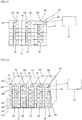
- FIG. 1 is a plan view showing a control center in a display control system according to Embodiment 1 of the present invention.
- FIG. 2 is a perspective view showing the display control system according to Embodiment 1 of the present invention.
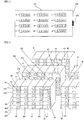
- FIG. 3 is a relevant part front view showing a circuit state in the display control system according to Embodiment 1 of the present invention.
- FIG. 4 is a perspective view showing the circuit state in the display control system according to Embodiment 1 of the present invention.
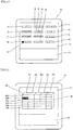
- FIG. 5 is a front view showing a display control unit in the display control system according to Embodiment 1 of the present invention.
- FIG. 6 is a front view showing the display control unit in the display control system according to Embodiment 1 of the present invention.
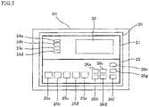
- FIG. 7 is a front view showing the display control unit in the display control system according to Embodiment 1 of the present invention.
- FIG. 1 shows a case where a control center 100 is arranged in an electrical room 200; and FIG. 2 shows the display control system.
- the control center 100 for example, six columns of measurement units each having a measurement device on which a measurement device display unit is not mounted, are arranged and unitized to constitute one panel; and, for example, five rows of the panels are juxtaposed to constitute one row panel and these row panels are arrayed in plurality.
- the drawing shows the case where row panels from a row panel A to a row panel M are arranged.
- the inspection and the maintenance are performed by opening a door 201 and by entering the room.
- the row panel D For example, in the row panel D, six columns of measurement units 40, for example, from a measurement unit 40a to a measurement unit 40f, each having a measurement device 30 on which the measurement device display unit is not mounted, are arranged and unitized to constitute one panel; and, for example, five rows of these panels from the panel D1 to the panel D5, are juxtaposed to constitute one row panel D.
- other row panels from the row panel A to the row panel C and from the row panel E to the row panel M are also similarly configured such that, for example, six columns of the measurement units 40 each having the measurement device 30 on which the measurement device display unit is not mounted, are arranged and unitized to constitute one panel; and, for example, five rows of these panels are juxtaposed to constitute one row panel, respectively.
- the measurement device 30 is not mounted with the measurement device display unit, but is mounted with a measurement device control unit.
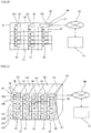
- a display control unit 50 which is provided on any one of the respective measurement units 40, is connected through a line by a wired circuit network 51 to each measurement device 30 of each measurement unit 40 (the measurement device 30 is not mounted with the measurement device display unit), and has a display unit 52 that displays each operation state of each measurement unit 40 and a control unit 53 that executes a control command to each of the respective measurement units 40.
- the display control unit 50 is provided on any one of the respective measurement units 40 in, for example, the row panel D of the row panels from the row panel A to the row panel M in the control center 100. More specifically, there is shown the case where the display control unit 50 is provided on the measurement unit 40 of the uppermost column of the panel D5 of the row panel D.
- a maintenance worker needs to confirm every day that there is no abnormality in a measured value and/or an operation state of each measurement device 30 on which the measurement device display unit is not mounted, each measurement device 30 being arranged in each measurement unit 40 of the row panels from the row panel A to the row panel M in a control center 100.
- the measured value and/or the operation state of each measurement device 30 on which the measurement device display unit is not mounted can be confirmed by the display control unit 50 arranged in, for example, the measurement unit 40 of the uppermost column of the panel D5 of the row panel D.
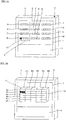
- the display control unit 50 has a screen configuration like the one shown in FIG. 5 to FIG. 7 .
- the display control unit 50 has the display unit 52 that displays each operation state of the respective measurement units 40 and the control unit 53 that executes the control command to each of the respective measurement units 40; and as shown in FIG. 5 , an array from the row panel A to the row panel M of the control center 100 is displayed by the display unit 52 of the display control unit 50.
- the maintenance worker confirms by the display unit 52 of the display control unit 50 that an abnormality occurs in the measured value and/or the operation state of the measurement device 30 on which the measurement device display unit is not mounted, the measurement device 30 being arranged in the measurement unit 40 of the panel D1 of the row panel D, it is possible to confirm that the abnormality occurs in the measurement unit 40b of the second column from the top of the panel D1 of the row panel D by operating the control unit 53 of the display control unit 50 as shown in FIG. 6 .
- a screen of a measurement device display control block 20 that is similar to the measurement device display unit and the measurement device control unit of the measurement unit 40b is displayed on the display unit 52 of the display control unit 50 as shown in FIG. 7 by operating the control unit 53 of the display control unit 50.
- the measurement device display unit is displayed on the display unit 52 of the display control unit 50, the measurement device display unit is not mounted on each measurement device 30 of each measurement unit 40.
- the measurement device display unit is not mounted on each measurement device 30 of each measurement unit 40, whereby a considerable reduction in cost can be achieved.
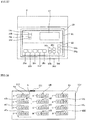
- the measurement device display block 21 of the measurement device display control block 20 is provided with a liquid crystal display 23 that displays a wide variety of numerical values and LED indication lamps from an LED indication lamp 24a to an LED indication lamp 24d.
- the LED indication lamp 24a displays ON; the LED indication lamp 24b, OFF; the LED indication lamp 24c, FAULT; and the LED indication lamp 24d, ERROR, respectively.
- the measurement device operation block 22 of the measurement device display control block 20 is provided with, for example, a direct control button block 25a, a remote control button 25b, a stop button 25c, a reverse rotation button 25d, a normal rotation button 25e, a MODE button 26a, a SET button 26b, an up button 26c, a down button 26d, a CLEAR/BACK button 26e, a RESET button 26f, and an external apparatus connection terminal 26g.
- inspection and maintenance can be performed so that an error numerical value displayed on the liquid crystal display 23 becomes a normal value by operating the direct control button block 25a, the remote control button 25b, the stop button 25c, the reverse rotation button 25d, the normal rotation button 25e, the MODE button 26a, the SET button 26b, the up button 26c, the down button 26d, the CLEAR/BACK button 26e, the RESET button 26f, the external apparatus connection terminal 26g, and the like which are provided on the measurement device operation block 22 of the measurement device display control block 20.
- the measurement device display unit is configured not to be mounted on each measurement device 30 of the plurality of arrayed measurement units 40, and the display control unit 50 that is connected through the line to each of the respective measurement units 40 is provided on any one of the measurement units 40, whereby the display control system capable of achieving a considerable reduction in cost can be obtained.
- the measurement device 30 of the measurement unit 40 to be targeted can be searched by the display control unit 50, inspection and maintenance of the measurement device 30 of the measurement unit 40 to be targeted can be performed while making the round from the row panel A to the row panel M in the control center 100 without performing inspection and maintenance and the time required for daily inspection work of the maintenance worker can be considerably reduced.
- the inspection and the maintenance of the measurement device 30 of the measurement unit 40 to be targeted are performed by searching the measurement device 30 of the measurement unit 40 to be targeted by the display control unit 50 and by operating by the control unit 53 of the display control unit 50, but are not limited thereto; and after searching the measurement device 30 of the measurement unit 40 to be targeted by the display control unit 50, the inspection and the maintenance of the measurement device 30 of the measurement unit 40 to be targeted may be performed by going in front of the measurement device 30 of the measurement unit 40 to be targeted and by operating the measurement device control unit of the measurement device 30.
- the display control unit 50 is provided on any one of the respective measurement units 40 in, for example, the row panel D of the row panels from the row panel A to the row panel M in the control center 100, but is not limited to this; and the display control unit 50 may be provided on each row panel and the same effects as the aforementioned Embodiment 1 can be exhibited.
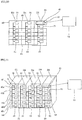
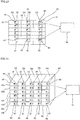
- FIG. 8 is a relevant part front view showing a circuit state in a display control system according to Embodiment 2 of the present invention.
- FIG. 9 is a perspective view showing the circuit state in the display control system according to Embodiment 2 of the present invention.
- Embodiment 1 there has been described a case where the measurement device display unit is not mounted on each measurement device 30 of each measurement unit 40, but the measurement device control unit is mounted.
- a measurement device display unit and a measurement device control unit are configured not to be mounted on each measurement device 31 of each measurement unit 40.
- a maintenance worker confirms by a display unit 52 of a display control unit 50 that an abnormality occurs in a measured value and/or an operation state of the measurement device 31 on which the measurement device display unit and the measurement device control unit are not mounted, the measurement device 31 being arranged in the measurement unit 40 of a panel D1 of a row panel D, inspection and maintenance of the measurement device 31 of the measurement unit 40 to be targeted can be performed by operating a control unit 53 of the display control unit 50 as in the aforementioned Embodiment 1 and the time required for daily inspection work of the maintenance worker can be considerably reduced.
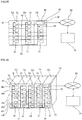
- FIG. 10 is a relevant part front view showing a circuit state in a display control system according to Embodiment 3 of the present invention.
- FIG. 11 is a perspective view showing the circuit state in the display control system according to Embodiment 3 of the present invention.
- FIG. 12 is a front view showing a monitoring control unit in the display control system according to Embodiment 3 of the present invention.
- FIG. 13 is a front view showing the monitoring control unit in the display control system according to Embodiment 3 of the present invention.
- FIG. 14 is a front view showing the monitoring control unit in the display control system according to Embodiment 3 of the present invention.
- a display control unit 60 which is provided on any one of respective measurement units 40, is connected through a line by a wired circuit network 51 to each measurement device 31 of each measurement unit 40 (the measurement device 31 is not mounted with a measurement device display unit and a measurement device control unit), and executes collection of each operation state and each control command of the respective measurement units 40.
- the display control unit 60 is mounted with a radio communication unit 61. There is shown a case where the display control unit 60 is provided on any one of the respective measurement units 40 in, for example, a row panel D of the row panels from the row panel A to the row panel M in the control center 100. More specifically, there is shown the case where the display control unit 60 is provided on the measurement unit 40 of the uppermost column of a panel D5 of the row panel D.
- monitoring control unit 70 which performs radio communication with the radio communication unit 61 mounted on the display control unit 60 as shown by a dotted line arrow, has a terminal display block 71 and a terminal operation block 72, and executes confirmation of each operation state and each control command of the respective measurement units 40.
- the monitoring control unit 70 is arranged in a management room near the control center 100 within a range capable of performing radio communication with, for example, the radio communication unit 61.
- a maintenance worker needs to confirm every day that there is no abnormality in a measured value and/or an operation state of each measurement device 31 on which the measurement device display unit and the measurement device control unit are not mounted, each measurement device 31 being arranged in each measurement unit 40 of the row panels from the row panel A to the row panel M in the control center 100.
- each measurement device 31 on which the measurement device display unit and the measurement device control unit are not mounted is confirmed by performing radio communication as shown by the dotted line between the monitoring control unit 70 and the radio communication unit 61 mounted on the display control unit 60 arranged in, for example, the measurement unit 40 of the uppermost column of the panel D5 of the row panel D.
- the monitoring control unit 70 has a screen configuration like the one shown in FIG. 12 to FIG. 14 .
- the monitoring control unit 70 has the terminal display block 71 that displays each operation state of the respective measurement units 40 and the terminal operation block 72 that executes the control command to each of the respective measurement units 40. Then, as shown in FIG. 12 , an array from the row panel A to a row panel Z in the control center 100 is displayed by the terminal display block 71 of the monitoring control unit 70.
- the maintenance worker confirms by the terminal display block 71 of the monitoring control unit 70 that an abnormality occurs in the measured value and/or the operation state of the measurement device 31 on which the measurement device display unit and the measurement device control unit are not mounted, the measurement device 31 being arranged in the measurement unit 40 of the panel D1 of the row panel D, it is possible to confirm that the abnormality occurs in a measurement unit 40b of the second column from the top of the panel D1 of the row panel D by operating the terminal operation block 72 of the monitoring control unit 70 as shown in FIG. 13 .
- a screen of a measurement device display control block 20 that is similar to the measurement device display unit and the measurement device control unit of the measurement unit 40b is displayed on the terminal display block 71 of the monitoring control unit 70 by operating the terminal operation block 72 of the monitoring control unit 70 as shown in FIG. 14 .
- the measurement device display unit and the measurement device control unit are displayed on the terminal display block 71 of the monitoring control unit 70, the measurement device display unit and the measurement device control unit are not mounted on each measurement unit 40 of each measurement device 31.
- the measurement device display unit and the measurement device control unit are not mounted on each measurement device 31 of each measurement unit 40, whereby a considerable reduction in cost can be achieved.
- the measurement device display block 21 of the measurement device display control block 20 is provided with a liquid crystal display 23 that displays a wide variety of numerical values and LED indication lamps from an LED indication lamp 24a to an LED indication lamp 24d.
- the LED indication lamp 24a displays ON; the LED indication lamp 24b, OFF; the LED indication lamp 24c, FAULT; and the LED indication lamp 24d, ERROR, respectively.
- the measurement device operation block 22 of the measurement device display control block 20 is provided with, for example, a direct control button block 25a, a remote control button 25b, a stop button 25c, a reverse rotation button 25d, a normal rotation button 25e, a MODE button 26a, a SET button 26b, an up button 26c, a down button 26d, a CLEAR/BACK button 26e, a RESET button 26f, and an external apparatus connection terminal 26g.
- inspection and maintenance can be performed so that an error numerical value displayed on the liquid crystal display 23 becomes a normal value by operating the direct control button block 25a, the remote control button 25b, the stop button 25c, the reverse rotation button 25d, the normal rotation button 25e, the MODE button 26a, the SET button 26b, the up button 26c, the down button 26d, the CLEAR/BACK button 26e, the RESET button 26f, the external apparatus connection terminal 26g, and the like which are provided on the measurement device operation block 22 of the measurement device display control block 20.
- the measurement device display unit and the measurement device control unit are configured not to be mounted on each measurement device 31 of the plurality of arrayed measurement units 40; the display control unit 60 connected through the line to each of the respective measurement units 40 and the radio communication unit 61 mounted on the display control unit 60 are mounted on any one of the measurement units 40; and there includes the monitoring control unit 70 which performs radio communication with the radio communication unit 61 as shown by the dotted line arrow, has the terminal display block 71 and the terminal operation block 72, and executes confirmation of each operation state and each control command of the respective measurement units 40, whereby the display control system capable of achieving a considerable reduction in cost can be obtained.
- the measurement device 31 of the measurement unit 40 to be targeted can be searched by the display control unit 70, inspection and maintenance of the measurement device 31 of the measurement unit 40 to be targeted can be performed while making the round from the row panel A to the row panel M in the control center 100 without performing inspection and maintenance and the time required for daily inspection work of the maintenance worker can be considerably reduced.
- the display control unit 60 is provided on any one of the respective measurement units 40 in, for example, the row panel D of the row panels from the row panel A to the row panel M in the control center 100, but is not limited to this.
- the display control unit 60 may be provided on each row panel and the same effects as the aforementioned Embodiment 1 can be exhibited.
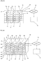
- FIG. 15 is a relevant part front view showing a circuit state in a display control system according to Embodiment 4 of the present invention.
- FIG. 16 is a perspective view showing the circuit state in the display control system according to Embodiment 4 of the present invention.
- Embodiment 4 of the present invention there includes a display control unit 65 constituted by a programmable logic controller, as the aforementioned display control unit 60 of Embodiment 3.
- the display control unit 65 constituted by the programmable logic controller is mounted with a radio communication unit 66.
- the display control unit 65 constituted by the programmable logic controller is provided on any one of respective measurement units 40 in, for example, a row panel D of row panels from a row panel A to a row panel M in a control center 100. More specifically, there is shown the case where the display control unit 65 is provided on the measurement unit 40 of the uppermost column of a panel D5 of the row panel D.
- monitoring control unit 70 which performs radio communication with the radio communication unit 66 mounted on the display control unit 65 as shown by a dotted line arrow, has a terminal display block 71 and a terminal operation block 72, and executes confirmation of each operation state and each control command of the respective measurement units 40.
- the monitoring control unit 70 is arranged in a management room near the control center 100 within a range capable of performing radio communication with, for example, the radio communication unit 66.
- a maintenance worker needs to confirm every day that there is no abnormality in a measured value and/or an operation state of each measurement device 31 on which a measurement device display unit and a measurement device control unit are not mounted, each measurement device 31 being arranged in each measurement unit 40 of the row panels from the row panel A to the row panel M in the control center 100.
- each measurement device 31 on which the measurement device display unit and the measurement device control unit are not mounted is confirmed by performing radio communication as shown by the dotted line between the monitoring control unit 70 and the radio communication unit 66 mounted on the display control unit 65 constituted by the programmable logic controller, the display control unit 65 being arranged in, for example, the measurement unit 40 of the uppermost column of the panel D5 of the row panel D.
- the measurement device display unit and the measurement device control unit are configured not to be mounted on each measurement device 31 of the plurality of arrayed measurement units 40;
- the display control unit 65 constituted by the programmable logic controller, which is connected through the line to each of the respective measurement units 40, and the radio communication unit 66 mounted on the display control unit 65 are mounted on any one of the measurement units 40; and there includes the monitoring control unit 70 which performs radio communication with the radio communication unit 66 as shown by the dotted line arrow, has the terminal display block 71 and the terminal operation block 72, and executes confirmation of each operation state and each control command of the respective measurement units 40, whereby the display control system capable of achieving a considerable reduction in cost can be obtained.
- the measurement device 31 of the measurement unit 40 to be targeted can be searched by the display control unit 70, inspection and maintenance of the measurement device 31 of the measurement unit 40 to be targeted can be performed while making the round from the row panel A to the row panel M in the control center 100 without performing inspection and maintenance and the time required for daily inspection work of the maintenance worker can be considerably reduced.
- the display control unit 60 is provided on any one of the respective measurement units 40 in, for example, the row panel D of the row panels from the row panel A to the row panel M in the control center 100, but is not limited to this.
- the display control unit 65 may be provided on each row panel and the same effects as the aforementioned Embodiment 4 can be exhibited.
- FIG. 17 is a relevant part front view showing a circuit state in a display control system according to Embodiment 5 of the present invention.
- FIG. 18 is a perspective view showing the circuit state in the display control system according to Embodiment 5 of the present invention.
- Embodiment 3 there has been described the case where the measurement device display unit and the measurement device control unit are configured not to be mounted on each measurement device 31 of the plurality of arrayed measurement units 40; however, in this Embodiment 5, there is shown a case where each measurement device 30 of a plurality of arrayed measurement units 40 is not mounted with a measurement device display unit, but is mounted with a measurement device control unit.
- each measurement device 30 of the plurality of arrayed measurement units 40 is not mounted with the measurement device display unit, but is mounted with the measurement device control unit, in the case of searching the measurement device 30 of the measurement unit 40 to be targeted for inspection and maintenance by a monitoring control unit 70, the search is informed to a maintenance worker when the maintenance worker is present in a control center 100 or near the control center 100, the maintenance worker goes in front of the measurement device 30 of the measurement unit 40 to be targeted for inspection and maintenance and operates the measurement device control unit of the measurement device 30, so that the inspection and the maintenance of the measurement device 30 of the measurement unit 40 to be targeted can be performed directly.
- FIG. 19 is a relevant part front view showing a circuit state in a display control system according to Embodiment 6 of the present invention.
- FIG. 20 is a perspective view showing the circuit state in the display control system according to Embodiment 6 of the present invention.
- Embodiment 4 there has been described the case where the measurement device display unit and the measurement device control unit are configured not to be mounted on each measurement device 31 of the plurality of arrayed measurement units 40; however, in this Embodiment 6, there is shown a case where each measurement device 30 of a plurality of arrayed measurement units 40 is not mounted with a measurement device display unit, but is mounted with a measurement device control unit.
- each measurement device 30 of the plurality of arrayed measurement units 40 is not mounted with the measurement device display unit, but is mounted with the measurement device control unit, in the case of searching the measurement device 30 of the measurement unit 40 to be targeted for inspection and maintenance by a monitoring control unit 70, the search is informed to a maintenance worker when the maintenance worker is present in a control center 100 or near the control center 100, the maintenance worker goes in front of the measurement device 30 of the measurement unit 40 to be targeted for inspection and maintenance and operates the measurement device display control unit of the measurement device 30, so that the inspection and the maintenance of the measurement device 30 of the measurement unit 40 to be targeted can be performed directly.
- FIG. 21 is a relevant part front view showing a circuit state in a display control system according to Embodiment 7 of the present invention.
- FIG. 22 is a perspective view showing the circuit state in the display control system according to Embodiment 7 of the present invention.
- measurement units 40 which are arrayed in plurality and each of which has a measurement device 31 on which a measurement device display unit and a measurement device control unit are not mounted; radio communication units 80 each provided on each measurement device 31 of each measurement unit 40; and a monitoring control unit 70 which performs radio communication with the radio communication units 80, has a terminal display block 71 and a terminal operation block 72, and executes confirmation of each operation state and each control command of the respective measurement units 40.
- a measured value and/or an operation state of each measurement device 31 on which the measurement device display unit and the measurement device control unit are not mounted is confirmed by performing radio communication between a radio communication unit 80 mounted on each measurement device 31 of each measurement unit 40 and the monitoring control unit 70 as shown by a dotted line.
- the terminal display block 71 of the monitoring control unit 70 confirms by the terminal display block 71 of the monitoring control unit 70 that an abnormality occurs in the measured value and/or the operation state of the measurement device 31 on which the measurement device display unit and the measurement device control unit are not mounted, the measurement device 31 being arranged in the measurement unit 40 of a panel D1 of a row panel D, it is possible to confirm that the abnormality occurs in a measurement unit 40b of the second column from the top of the panel D1 of the row panel D by operating the terminal operation block 72 of the monitoring control unit 70 as shown in FIG. 13 .
- a screen of a measurement device display control block 20 that is similar to the measurement device display unit and the measurement device control unit of the measurement unit 40b is displayed on the terminal display block 71 of the monitoring control unit 70 by operating the terminal operation block 72 of the monitoring control unit 70 as shown in FIG. 14 . More specifically, since the measurement device display unit and the measurement device control unit are displayed on the terminal display block 71 of the monitoring control unit 70, the measurement device display unit and the measurement device control unit are not mounted on each measurement device 31 of each measurement unit 40. The measurement device display unit and the measurement device control unit are not mounted on each measurement device 31 of each measurement unit 40, whereby a considerable reduction in cost can be achieved.
- the measurement device display unit and the measurement device control unit are configured not to be mounted on each measurement device 31 of the plurality of arrayed measurement units 40; the radio communication unit 80 is mounted on the measurement device 31 of each measurement unit 40; and there includes the monitoring control unit 70 which performs radio communication with the radio communication units 80 as shown by the dotted line arrows, has the terminal display block 71 and the terminal operation block 72, and executes confirmation of each operation state and each control command of the respective measurement units 40, whereby the display control system capable of achieving a considerable reduction in cost can be obtained.
- the measurement device 31 of the measurement unit 40 to be targeted can be searched by the display control unit 70, inspection and maintenance of the measurement device 31 of the measurement unit 40 to be targeted can be performed while making the round from a row panel A to a row panel M in the control center 100 without performing inspection and maintenance and the time required for daily inspection work of the maintenance worker can be considerably reduced.
- FIG. 23 is a relevant part front view showing a circuit state in a display control system according to Embodiment 8 of the present invention.
- FIG. 24 is a perspective view showing the circuit state in the display control system according to Embodiment 8 of the present invention.
- each measurement device 30 of a plurality of arrayed measurement units 40 is not mounted with a measurement device display unit, but is mounted with a measurement device control unit.
- each measurement device 30 of the plurality of arrayed measurement units 40 is not mounted with the measurement device display unit, but is mounted with the measurement device control unit, in the case of searching the measurement device 30 of the measurement unit 40 to be targeted for inspection and maintenance by a monitoring control unit 70, the search is informed to a maintenance worker when the maintenance worker is present in a control center 100 or near the control center 100, the maintenance worker goes in front of the measurement device 30 of the measurement unit 40 to be targeted for inspection and maintenance and operates the measurement device control unit of the measurement device 30, so that the inspection and the maintenance of the measurement device 30 of the measurement unit 40 to be targeted can be performed directly.
- FIG. 25 is a relevant part front view showing a circuit state in a display control system according to Embodiment 9 of the present invention.
- FIG. 26 is a perspective view showing the circuit state in the display control system according to Embodiment 9 of the present invention.
- a display control unit 90 which is provided on any one of respective measurement units 40, is connected through a line by a wired circuit network 51 to each measurement device 31 of each measurement unit 40 (the measurement device 31 is not mounted with a measurement device display unit and a measurement device control unit), and executes collection of each operation state and each control command of the respective measurement units 40.
- the display control unit 90 is mounted with a wired communication unit 91. There is shown a case where the display control unit 90 is provided on any one of the respective measurement units 40 in, for example, a row panel D of the row panels from the row panel A to the row panel M in the control center 100. More specifically, there is shown the case where the display control unit 90 is provided on the measurement unit 40 of the uppermost column of a panel D5 of the row panel D.
- the wired communication unit 91 mounted on the display control unit 90 performs wired communication with a network circuit 92 as shown by a solid line arrow. Then, there includes a monitoring control unit 70 which performs radio communication with the network circuit 92 as shown by a dotted line arrow, has a terminal display block 71 and a terminal operation block 72, and executes confirmation of each operation state and each control command of the respective measurement units 40.
- the monitoring control unit 70 can perform radio communication with, for example, the network circuit 92, the monitoring control unit 70 may not be arranged in a management room near the control center 100 as in the aforementioned Embodiment 3, can be arranged at a more distant place than the control center 100, and can be remotely operated.
- a maintenance worker needs to confirm every day that there is no abnormality in a measured value and/or an operation state of each measurement device 31 on which the measurement device display unit and the measurement device control unit are not mounted, each measurement device 31 being arranged in each measurement unit 40 of the row panels from the row panel A to the row panel M in the control center 100.
- each measurement device 31 on which the measurement device display unit and the measurement device control unit are not mounted is confirmed such that, for example, wired communication is performed between the network circuit 92 and the wired communication unit 91 mounted on the display control unit 90 that is arranged in the measurement unit 40 of the uppermost column of the panel D5 of the row panel D, and radio communication is performed between the network circuit 92 and the monitoring control unit 70 as shown by the dotted line.
- the measurement device display unit and the measurement device control unit are configured not to be mounted on each measurement device 31 of the plurality of arrayed measurement units 40; the display control unit 90 connected through the line to each of the respective measurement units 40 and the wired communication unit 91 mounted on the display control unit 90 are mounted on any one of the measurement units 40; wired communication is performed between the wired communication unit 91 and the network circuit 92 as shown by the solid line arrow; and there includes the monitoring control unit 70 which performs radio communication with the network circuit 92 as shown by the dotted line arrow, has the terminal display block 71 and the terminal operation block 72, and executes confirmation of each operation state and each control command of the respective measurement units 40, whereby the display control system capable of achieving a considerable reduction in cost can be obtained.
- the measurement device 31 of the measurement unit 40 to be targeted can be searched by the display control unit 70, inspection and maintenance of the measurement device 31 of the measurement unit 40 to be targeted can be performed while making the round from the row panel A to the row panel M in the control center 100 without performing inspection and maintenance and the time required for daily inspection work of the maintenance worker can be considerably reduced.
- the display control unit 90 is provided on any one of the respective measurement units 40 in, for example, the row panel D of the row panels from the row panel A to the row panel M in the control center 100, but is not limited to this.
- the display control unit 90 may be provided on each of the respective row panels and the same effects as the aforementioned Embodiment 9 can be exhibited.
- FIG. 27 is a relevant part front view showing a circuit state in a display control system according to Embodiment 10 of the present invention.
- FIG. 28 is a perspective view showing the circuit state in the display control system according to Embodiment 10 of the present invention.
- each measurement device 30 of a plurality of arrayed measurement units 40 is not mounted with a measurement device display unit, but is mounted with a measurement device control unit.
- each measurement device 30 of the plurality of arrayed measurement units 40 is not mounted with the measurement device display unit, but is mounted with the measurement device control unit, in the case of searching the measurement device 30 of the measurement unit 40 to be targeted for inspection and maintenance by a monitoring control unit 70, the search is informed to a maintenance worker when the maintenance worker is present in a control center 100 or near the control center 100, the maintenance worker goes in front of the measurement device 30 of the measurement unit 40 to be targeted for inspection and maintenance and operates the measurement device control unit of the measurement device 30, so that the inspection and the maintenance of the measurement device 30 of the measurement unit 40 to be targeted can be performed directly.
- FIG. 29 is a relevant part front view showing a circuit state in a display control system according to Embodiment 11 of the present invention.
- FIG. 30 is a perspective view showing the circuit state in the display control system according to Embodiment 11 of the present invention.
- Embodiment 11 of the present invention there includes a display control unit 95 constituted by a programmable logic controller, as the aforementioned display control unit 90 of Embodiment 9.
- the display control unit 95 constituted by the programmable logic controller is mounted with a wired communication unit 96.
- the display control unit 95 constituted by the programmable logic controller is provided on any one of respective measurement units 40 in, for example, a row panel D of row panels from a row panel A to a row panel M in a control center 100. More specifically, there is shown the case where the display control unit 95 is provided on the measurement unit 40 of the uppermost column of a panel D5 of the row panel D.
- the wired communication unit 96 mounted on the display control unit 95 constituted by the programmable logic controller performs wired communication with a network circuit 92 as shown by a solid line arrow. Then, there includes a monitoring control unit 70 which performs radio communication with the network circuit 92 as shown by a dotted line arrow, has a terminal display block 71 and a terminal operation block 72, and executes confirmation of each operation state and each control command of the respective measurement units 40.
- the monitoring control unit 70 can perform radio communication with, for example, the network circuit 92, the monitoring control unit 70 may not be arranged in a management room near the control center 100 as in the aforementioned Embodiment 3, can be arranged at a more distant place than the control center 100, and can be remotely operated.
- a maintenance worker needs to confirm every day that there is no abnormality in a measured value and/or an operation state of each measurement device 31 on which the measurement device display unit and the measurement device control unit are not mounted, each measurement device 31 being arranged in each measurement unit 40 of the row panels from the row panel A to the row panel M in the control center 100.
- each measurement device 31 on which the measurement device display unit and the measurement device control unit are not mounted is confirmed such that, for example, wired communication is performed between the network circuit 92 and the wired communication unit 96 mounted on the display control unit 95 constituted by the programmable logic controller that is arranged in the measurement unit 40 of the uppermost column of the panel D5 of the row panel D, and radio communication is performed between the network circuit 92 and the monitoring control unit 70 as shown by the dotted line.
- the measurement device display unit and the measurement device control unit are configured not to be mounted on each measurement device 31 of the plurality of arrayed measurement units 40; the display control unit 95 constituted by the programmable logic controller, the display control unit 95 being connected through the line to each of the respective measurement units 40, and the wired communication unit 96 mounted on the display control unit 95 constituted by the programmable logic controller are mounted on any one of the measurement units 40; wired communication is performed between the wired communication unit 96 and the network circuit 92 as shown by the solid line arrow; and there includes the monitoring control unit 70 which performs radio communication with the network circuit 92 as shown by the dotted line arrow, has the terminal display block 71 and the terminal operation block 72, and executes confirmation of each operation state and each control command of the respective measurement units 40, whereby the display control system capable of achieving a considerable reduction in cost can be obtained.
- the measurement device 31 of the measurement unit 40 to be targeted can be searched by the display control unit 70, inspection and maintenance of the measurement device 31 of the measurement unit 40 to be targeted can be performed while making the round from the row panel A to the row panel M in the control center 100 without performing inspection and maintenance and the time required for daily inspection work of the maintenance worker can be considerably reduced.
- the display control unit 95 constituted by the programmable logic controller is provided on any one of the respective measurement units 40 in, for example, the row panel D of the row panels from the row panel A to the row panel M in the control center 100, but is not limited to this.
- the display control unit 95 constituted by the programmable logic controller may be provided on each of the respective row panels and the same effects as the aforementioned Embodiment 11 can be exhibited.
- FIG. 31 is a relevant part front view showing a circuit state in a display control system according to Embodiment 12 of the present invention.
- FIG. 32 is a perspective view showing the circuit state in the display control system according to Embodiment 12 of the present invention.
- each measurement device 30 of a plurality of arrayed measurement units 40 is not mounted with a measurement device display unit, but is mounted with a measurement device control unit.
- each measurement device 30 of the plurality of arrayed measurement units 40 is not mounted with the measurement device display unit, but is mounted with the measurement device control unit, in the case of searching the measurement device 30 of the measurement unit 40 to be targeted for inspection and maintenance by a monitoring control unit 70, the search is informed to a maintenance worker when the maintenance worker is present in a control center 100 or near the control center 100, the maintenance worker goes in front of the measurement device 30 of the measurement unit 40 to be targeted for inspection and maintenance and operates the measurement device control unit of the measurement device 30, so that the inspection and the maintenance of the measurement device 30 of the measurement unit 40 to be targeted can be performed directly.
- the monitoring control unit 70 may constituted by, for example, a touch panel terminal or a tablet terminal and the same effects can be exhibited.
- FIG. 33 is a plan view showing a control center in a specific position navigation system according to Embodiment 13 of the present invention.
- FIG. 34 is a perspective view showing the control center in the specific position navigation system according to Embodiment 13 of the present invention.
- FIG. 35 is a perspective view showing the specific position navigation system according to Embodiment 13 of the present invention.
- FIG. 36 is a perspective view showing the specific position navigation system according to Embodiment 13 of the present invention.
- FIG. 37 is a front view showing the measurement device of the control center according to Embodiment 13 of the present invention.
- FIG. 33 shows a case where a control center 110 is arranged in an electrical room 210.
- the control center 100 for example, six columns of measurement units 4 each constituted by a load nameplate 1 and a measurement device 2, are arranged and unitized to constitute one panel; and, for example, five rows of the panels are juxtaposed to constitute one row panel and these row panels are arrayed in plurality. More specifically, by way of an example, the drawing shows the case where row panels from a row panel A to a row panel M are arranged.
- the inspection and the maintenance are performed by opening a door 211 and by entering the room.
- the row panel D six columns of the measurement units 4, for example, from a measurement unit 4a to a measurement unit 4f, each constituted by the load nameplate 1 and the measurement device 2, are arranged and unitized to constitute one panel; and, for example, five rows of these panels from a panel D1 to a panel D5, are juxtaposed to constitute one row panel D.
- other row panels from the row panel A to the row panel C and from the row panel E to the row panel M are also similarly configured such that, for example, six columns of the measurement units 4 each constituted by the load nameplate 1 and the measurement device 2, are arranged and unitized to constitute one panel; and, for example, five rows of these panels are juxtaposed to constitute one row panel, respectively.
- a maintenance worker confirms every day while going round in sequence that there is no abnormality in a measured value and/or an operation state of each measurement device 2 arranged in each measurement unit 4.
- the maintenance worker confirms that an abnormality occurs in the measured value and/or the operation state of the measurement device 2 arranged in the measurement unit 4, for example, in FIG. 34 , in the case where the abnormality occurs in the measurement unit 4b of the second column from the top of the panel D1 of the row panel D, the maintenance worker can navigate to the position of the measurement device 2 of the measurement unit 4b to be targeted for the inspection and maintenance.
- a radio communication terminal device 6A to 6M is arranged in each of the row panels from the row panel A to the row panel M, respectively; the maintenance worker opens the door 211 of the electrical room 210 and enters therein and performs radio transmission from a terminal radio communication portion 8 of a radio communication terminal unit 5 to a plurality of radio communication terminal devices, the terminal radio communication portion 8 being constituted by, for example, a tablet terminal in which a maintenance worker has, whereby the present position of the radio communication terminal unit 5 is specified by a location information service system (not shown in the drawing).
- a distance is calculated backward from radio wave strength between the radio communication terminal unit 5 and each of the radio communication terminal devices 6A to 6M arranged in the row panels from A to the row panel M, whereby the distance from the radio communication terminal device can be measured by receiving radio waves of three or more radio communication terminal devices and by measuring the strength and the position of the radio communication terminal unit 5 can be specified by measuring three or more distances.
- a load name, a row panel code, and the like of the measurement device of an inspection object to be specified for example, the measurement unit 4b of the panel D1 of the row panel D
- radio transmission is performed to, for example, the radio communication terminal device 6A of the row panel A.
- a navigation screen which navigates by, for example, a route R to the panel D1 of the row panel D of an inspection object to be specified is displayed on a terminal display block 7 of the radio communication terminal unit 5 through, for example, the radio communication terminal device 6A as shown in FIG. 35 ; and the maintenance worker proceeds along the route R while watching the navigation screen.
- the measurement unit 4b of the panel D1 of the row panel D which is the inspection object to be specified, is specified as shown in FIG. 36 .
- the route R to the position of the measurement device of the measurement unit to be targeted can be navigated and the moving time of the maintenance worker to the position of the measurement device of the measurement unit to be targeted and the searching time of the measurement device of the measurement unit to be targeted can be reduced: and therefore, a reduction of maintenance cost can be achieved.
- the maintenance of the measurement unit 4b of the panel D1 is performed in the measurement device 2 of the measurement unit 4b and an example of a measurement device display block 21 and a measurement device operation block 22 of a measurement device display control block 20 of the measurement device 2 will be described on the basis of FIG. 37 .
- the measurement device display block 21 of the measurement device display control block 20 is provided with a liquid crystal display 23 that displays a wide variety of numerical values and LED indication lamps from an LED indication lamp 24a to an LED indication lamp 24d.
- the LED indication lamp 24a displays ON; the LED indication lamp 24b, OFF; the LED indication lamp 24c, FAULT; and the LED indication lamp 24d, ERROR, respectively.
- the measurement device operation block 22 of the measurement device display control block 20 is provided with, for example, a direct control button block 25a, a remote control button 25b, a stop button 25c, a reverse rotation button 25d, a normal rotation button 25e, a MODE button 26a, a SET button 26b, an up button 26c, a down button 26d, a CLEAR/BACK button 26e, a RESET button 26f, and an external apparatus connection terminal 26g.
- inspection and maintenance can be performed by operating the direct control button block 25a, the remote control button 25b, the stop button 25c, the reverse rotation button 25d, the normal rotation button 25e, the MODE button 26a, the SET button 26b, the up button 26c, the down button 26d, the CLEAR/BACK button 26e, the RESET button 26f, the external apparatus connection terminal 26g, and the like which are provided on the measurement device operation block 22 of the measurement device display control block 20.
- FIG. 38 is a plan view showing a control center in a specific position navigation system according to Embodiment 14 of the present invention.
- FIG. 39 is a relevant part perspective view showing a row panel in the specific position navigation system according to Embodiment 14 of the present invention.
- FIG. 40 is a perspective view showing the specific position navigation system according to Embodiment 14 of the present invention.
- FIG. 41 is a perspective view showing the specific position navigation system according to Embodiment 14 of the present invention.
- Embodiment 13 there has been described the case where the distance is calculated backward from the radio wave strength between the radio communication terminal unit 5 and each of the radio communication terminal devices 6A to 6M arranged in the row panels from A to the row panel M, whereby the distance from the radio communication terminal device is measured by receiving radio waves of three or more radio communication terminal devices and by measuring the strength and the position of the radio communication terminal unit 5 is specified by measuring three or more distances.
- a name of a load nameplate 1 of a measurement unit 4a of a row panel near a door 211 of an electrical room 211 for example, a panel A5 of a row panel A is imaged by an imaging unit such as a camera (not shown in the drawing) provided on a radio communication terminal unit 5 and radio transmission of imaging data imaged by the imaging unit of the radio communication terminal unit 5 is performed from a terminal radio communication portion 8 of the radio communication terminal unit 5 to, for example, a radio communication terminal device 6B, whereby its information is analyzed on the management database side and the position of the radio communication terminal unit 5 is specified.
- an imaging unit such as a camera (not shown in the drawing) provided on a radio communication terminal unit 5
- radio transmission of imaging data imaged by the imaging unit of the radio communication terminal unit 5 is performed from a terminal radio communication portion 8 of the radio communication terminal unit 5 to, for example, a radio communication terminal device 6B, whereby its information is analyzed on the management database side and the position of the radio communication terminal unit 5 is specified.
- a load name, a row panel code, and the like of the measurement device of an inspection object to be specified for example, a measurement unit 4b of a panel D1 of a row panel D
- radio transmission is performed to, for example, the radio communication terminal device 6B of a row panel B. Its information is analyzed on the management database side, as shown in FIG.
- a navigation screen which navigates by, for example, a route S to the panel D1 of the row panel D of the inspection object to be specified is displayed on a terminal display block 7 of the radio communication terminal unit 5 through, for example, the radio communication terminal device 6B; and a maintenance worker proceeds along the route S while watching the navigation screen and can reach in front of the panel D1 of the row panel D of the inspection object.
- the name of the load nameplate 1 of the measurement unit 4a of the row panel near the door 211 of the electrical room 211 for example, the panel A5 of the row panel A is imaged by the imaging unit such as the camera (not shown in the drawing) of the radio communication terminal unit 5 and radio transmission of the imaging data is performed from the terminal radio communication portion 8 of the radio communication terminal unit 5 to, for example, the radio communication terminal device 6B, whereby its information is analyzed on the management database side and the position of the radio communication terminal unit 5 is specified.
- the load name, the row panel code, and the like of the measurement device of the inspection object to be specified is input by the terminal operation block 6 of the radio communication terminal unit 5 and radio transmission is performed to, for example, the radio communication terminal device 6B of the row panel B, whereby the information is analyzed on the management database side and the navigation screen which navigates by, for example, the route S to the panel D1 of the row panel D of the inspection object to be specified is displayed on the terminal display block 7 of the radio communication terminal unit 5 as shown in FIG. 41 through, for example, the radio communication terminal device 6B.
- the route S to the position of the measurement device of the measurement unit to be targeted can be navigated and the moving time of the maintenance worker to the position of the measurement device of the measurement unit to be targeted and the searching time of the measurement device of the measurement unit to be targeted can be reduced; and thus, a reduction of maintenance cost can be achieved.
- FIG. 42 is a perspective view showing a specific position navigation system according to Embodiment 15 of the present invention.
- Embodiment 14 there has been described the case where the name of the load nameplate 1 of the measurement unit 4a of the row panel near the door 211 of the electrical room 211, for example, the panel A5 of the row panel A is imaged by the imaging unit such as the camera (not shown in the drawing) of the radio communication terminal unit 5 and radio transmission of the imaging data is performed from the terminal radio communication portion 8 of the radio communication terminal unit 5 to, for example, the radio communication terminal device 6B, whereby its information is analyzed on the management database side and the position of the radio communication terminal unit 5 is specified.
- the imaging unit such as the camera (not shown in the drawing) of the radio communication terminal unit 5
- radio transmission of the imaging data is performed from the terminal radio communication portion 8 of the radio communication terminal unit 5 to, for example, the radio communication terminal device 6B, whereby its information is analyzed on the management database side and the position of the radio communication terminal unit 5 is specified.
- each row panel is provided with an information code, that is, a bar code 11 which specifies a load nameplate 1.
- the bar code 11 which specifies the load nameplate 1 of, for example, a measurement unit 4a of a panel A5 of a row panel A is read by a reader (not shown in the drawing) provided on a radio communication terminal unit 5 and radio transmission of data of the bar code 11 is performed from a terminal radio communication portion 8 to, for example, a radio communication terminal device 6B, whereby its information is analyzed on the management database side and the position of the radio communication terminal unit 5 is specified.
- a load name, a row panel code, and the like of the measurement device of an inspection object to be specified for example, a measurement unit 4b of a panel D1 of a row panel D
- radio transmission is performed to, for example, the radio communication terminal device 6B of a row panel B.
- a navigation screen which navigates by, for example, a route S to the panel D1 of the row panel D of the inspection object to be specified is displayed on a terminal display block 7 of the radio communication terminal unit 5 as shown in FIG. 41 through, for example, the radio communication terminal device 6B; and a maintenance worker proceeds along the route S while watching the navigation screen and can reach in front of the panel D1 of the row panel D of the inspection object.
- the bar code 11 which specifies the load nameplate 1 of the row panel near a door 211 of an electrical room 211, for example, the measurement unit 4a of the panel A5 of the row panel A, is read by the reader (not shown in the drawing) of the radio communication terminal unit 5 and radio transmission of the data of the bar code 11 is performed from the terminal radio communication portion 8 of the radio communication terminal unit 5 to, for example, the radio communication terminal device 6B, whereby its information is analyzed on the management database side and the position of the radio communication terminal unit 5 is specified.
- the load name, the row panel code, and the like of the measurement device of the inspection object to be specified is input by the terminal operation block 6 of the radio communication terminal unit 5 and radio transmission is performed to, for example, the radio communication terminal device 6B of the row panel B, whereby its information is analyzed on the management database side and the navigation screen which navigates by, for example, the route S to the panel D1 of the row panel D of the inspection object to be specified is displayed on the terminal display block 7 of the radio communication terminal unit 5 as shown in FIG. 41 through, for example, the radio communication terminal device 6B.
- the route S to the position of the measurement device of the measurement unit to be targeted can be navigated and the moving time of the maintenance worker to the position of the measurement device of the measurement unit to be targeted and the searching time of the measurement device of the measurement unit to be targeted can be reduced; and thus, a reduction of maintenance cost can be achieved.
- FIG. 43 is a perspective view showing a specific position navigation system according to Embodiment 16 of the present invention.
- FIG. 44 is a front view showing a two-dimensional code in the specific position navigation system according to Embodiment 16 of the present invention.
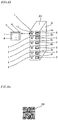
- a two-dimensional code 12 that specifies a load nameplate 1 like the one shown in FIG. 44 is provided on each row panel.
- An information code that is, a two-dimensional code 12 which specifies the load nameplate 1 of, for example, a measurement unit 4a of a panel A5 of a row panel A, is read by a reader (not shown in the drawing) provided on a radio communication terminal unit 5 and radio transmission of data of the two-dimensional code 12 is performed from a terminal radio communication portion 8 to, for example, a radio communication terminal device 6B, whereby its information is analyzed on the management database side and the position of the radio communication terminal unit 5 is specified.
- a load name, a row panel code, and the like of a measurement device of an inspection object to be specified is input by a terminal operation block 6 of the radio communication terminal unit 5 and radio transmission is performed to, for example, the radio communication terminal device 6B of a row panel B.
- Its information is analyzed on the management database side; and a navigation screen which navigates by, for example, a route S to the panel D1 of the row panel D of the inspection object to be specified is displayed on a terminal display block 7 of the radio communication terminal unit 5 as shown in FIG. 41 through, for example, the radio communication terminal device 6B; and a maintenance worker proceeds along the route S while watching the navigation screen and can reach in front of the panel D1 of the row panel D of the inspection object.
- the two-dimensional code 12 which specifies the load nameplate 1 of the row panel near a door 211 of an electrical room 211, for example, the measurement unit 4a of the panel A5 of the row panel A, is read by the reader (not shown in the drawing) of the radio communication terminal unit 5 and radio transmission of the data of the two-dimensional code 12 is performed from the terminal radio communication portion 8 of the radio communication terminal unit 5 to, for example, the radio communication terminal device 6B, whereby its information is analyzed on the management database side and the position of the radio communication terminal unit 5 is specified.
- the load name, the row panel code, and the like of the measurement device of the inspection object to be specified is input by the terminal operation block 6 of the radio communication terminal unit 5 and radio transmission is performed to, for example, the radio communication terminal device 6B of the row panel B, whereby its information is analyzed on the management database side and the navigation screen which navigates by, for example, the route S to the panel D1 of the row panel D of the inspection object to be specified is displayed on the terminal display block 7 of the radio communication terminal unit 5 as shown in FIG. 41 through, for example, the radio communication terminal device 6B.
- the route S to the position of the measurement device of the measurement unit to be targeted can be navigated and the moving time of the maintenance worker to the position of the measurement device of the measurement unit to be targeted and the searching time of the measurement device of the measurement unit to be targeted can be reduced; and thus, a reduction of maintenance cost can be achieved.
- FIG. 45 is a perspective view showing a specific position navigation system according to Embodiment 17 of the present invention.
- FIG. 46 is a perspective view showing the specific position navigation system according to Embodiment 17 of the present invention.
- a radio frequency (RF) code 35 that specifies a measurement device 2 like the one shown in FIG. 46 is provided on the measurement device 2 of each row panel.
- the RF code 35 that specifies the measurement device 2 of, for example, a measurement unit 4a of a panel A5 of a row panel A is read by a reader (not shown in the drawing) provided on a radio communication terminal unit 5 and radio transmission of data of the RF code 35 is performed from a terminal radio communication portion 8 to, for example, a radio communication terminal device 6B, whereby its information is analyzed on the management database side and the position of the radio communication terminal unit 5 is specified.
- a load name, a row panel code, and the like of a measurement device of an inspection object to be specified is input by a terminal operation block 6 of the radio communication terminal unit 5 and radio transmission is performed to, for example, the radio communication terminal device 6B of a row panel B.
- a navigation screen which navigates by, for example, a route S to the panel D1 of the row panel D of the inspection object to be specified is displayed on a terminal display block 7 of the radio communication terminal unit 5 as shown in FIG. 9 through, for example, the radio communication terminal device 6B; and a maintenance worker proceeds along the route S while watching the navigation screen and can reach in front of the panel D1 of the row panel D of the inspection object.
- the RF code 35 which specifies the measurement device 2 of the row panel near a door 211 of an electrical room 211, for example, the measurement unit 4a of the panel A5 of the row panel A, is read by the reader (not shown in the drawing) of the radio communication terminal unit 5 and radio transmission of the data of the RF code 35 is performed from the terminal radio communication portion 8 of the radio communication terminal unit 5 to, for example, the radio communication terminal device 6B, whereby its information is analyzed on the management database side and the position of the radio communication terminal unit 5 is specified.
- the load name, the row panel code, and the like of the measurement device of the inspection object to be specified is input by the terminal operation block 6 of the radio communication terminal unit 5 and radio transmission is performed to, for example, the radio communication terminal device 6B of the row panel B, whereby its information is analyzed on the management database side and the navigation screen which navigates by, for example, the route S to the panel D1 of the row panel D of the inspection object to be specified is displayed on the terminal display block 7 of the radio communication terminal unit 5 as shown in FIG. 41 through, for example, the radio communication terminal device 6B.
- the route S to the position of the measurement device of the measurement unit to be targeted can be navigated and the moving time of the maintenance worker to the position of the measurement device of the measurement unit to be targeted and the searching time of the measurement device of the measurement unit to be targeted can be reduced; and thus, a reduction of maintenance cost can be achieved.
- FIG. 47 is a plan view showing a control center in a specific position navigation system according to Embodiment 18 of the present invention.
- FIG. 48 is a perspective view showing a management center in the specific position navigation system according to Embodiment 18 of the present invention.
- FIG. 49 is a perspective view showing a display device of the management center in the specific position navigation system according to Embodiment 18 of the present invention.
- a function that specifies at which electrical room a maintenance worker is present, more specifically, at which electrical room the position of a radio communication terminal unit 5 is located.
- the maintenance worker opens a door 211 of an electrical room 210 and enters therein and performs radio transmission from a terminal radio communication portion 8 of the radio communication terminal unit 5 to, for example, a radio communication terminal device 6A, the terminal radio communication portion 8 being constituted by, for example, a tablet terminal in which the maintenance worker has, whereby a position information display panel 57 provided on a management center 56 displays that the maintenance worker enters an electrical room of P2 as shown in FIG. 49 .
- a position information display panel 57 provided on a management center 56 displays that the maintenance worker enters an electrical room of P2 as shown in FIG. 49 .
- specifying of the position of the radio communication terminal unit 5 and navigation of a root to a measurement device that becomes an inspection object to be specified can be performed by any one of the aforementioned Embodiment 13 to Embodiment 17 and the moving time of the maintenance worker to the position of the measurement device of the measurement unit to be targeted and the searching time of the measurement device of the measurement unit to be targeted can be reduced; and therefore, a reduction of maintenance cost can be achieved.
- FIG. 50 is a plan view showing a control center in a specific position navigation system according to Embodiment 19 of the present invention.
- FIG. 51 is a perspective view showing a display device of a management center in the specific position navigation system according to Embodiment 19 of the present invention.
- a function that specifies at which electrical room a maintenance worker is present, more specifically, at which electrical room the position of a radio communication terminal unit 5 is located.
- the maintenance worker opens a door 211 of an electrical room 210 and enters therein and performs radio transmission from an ID reader 300 to, for example, a radio communication terminal device 6A by holding an identification (ID) card (not shown in the drawing) over the ID reader 300 provided in the electrical room 210, whereby a position information display panel 57 provided on a management center 56 displays that the maintenance worker enters an electrical room of P3 as shown in FIG. 51 .
- ID identification
- specifying of the position of the radio communication terminal unit 5 and navigation of a root to a measurement device that becomes an inspection object to be specified can be performed by any one of the aforementioned Embodiment 13 to Embodiment 17 and the moving time of the maintenance worker to the position of the measurement device of the measurement unit to be targeted and the searching time of the measurement device of the measurement unit to be targeted can be reduced; and therefore, a reduction of maintenance cost can be achieved.
- FIG. 52 is a plan view showing a control center in an information display system for panel equipment according to Embodiment 20 of the present invention.
- FIG. 53 is a perspective view showing the information display system for panel equipment according to Embodiment 20 of the present invention.
- FIG. 54 is a relevant part perspective view showing the information display system for panel equipment according to Embodiment 20 of the present invention.
- FIG. 55 is a perspective view showing a radio communication terminal unit in the information display system for panel equipment according to Embodiment 20 of the present invention.
- FIG. 56 is a perspective view showing the radio communication terminal unit in the information display system for panel equipment according to Embodiment 20 of the present invention.
- FIG. 57 is a perspective view showing the radio communication terminal unit in the information display system for panel equipment according to Embodiment 20 of the present invention.
- FIG. 58 is a perspective view showing the radio communication terminal unit in the information display system for panel equipment according to Embodiment 20 of the present invention.
- FIG. 59 is a front view showing a measurement device in the information display system for panel equipment according to Embodiment 20 of the present invention.
- FIG. 52 shows a case where a control center 120 is arranged in an electrical room 220; and FIG. 53 shows the information display system for panel equipment.
- the control center 120 for example, six columns of measurement units each constituted by a load nameplate and a measurement device and each having a radio communication block, are arranged and unitized to constitute one panel; and, for example, five rows of the panels are juxtaposed to constitute one row panel and these row panels are arrayed in plurality.
- the drawing shows the case where row panels from a row panel A to a row panel M are arranged.
- the inspection and the maintenance are performed by opening a door 221 and by entering the room.
- the row panel D For example, in the row panel D, six columns of measurement units 4, for example, from a measurement unit 4a to a measurement unit 4f, each constituted by a load nameplate 1 and a measurement device 2 and each having a radio communication block 36, are arranged and unitized to constitute one panel; and, for example, five rows of these panels from a panel D1 to a panel D5, are juxtaposed to constitute one row panel D.
- other row panels from the row panel A to the row panel C and from the row panel E to the row panel M are also similarly configured such that, for example, six columns of the measurement units 4 each constituted by the load nameplate 1 and the measurement device 2 and each having the radio communication block 36, are arranged and unitized to constitute one panel; and, for example, five rows of these panels are juxtaposed to constitute one row panel, respectively.
- a maintenance worker confirms every day while going round in sequence that there is no abnormality in a measured value and/or an operation state of each measurement device 2 arranged in each measurement unit 4.
- the maintenance worker When the maintenance worker confirms that an abnormality occurs in the measured value and/or the operation state of the measurement device 2 arranged in the measurement unit 4, for example, in FIG. 53 , in the case where the abnormality occurs in the measurement unit 4b of the second column from the top of the panel D1 of the row panel D, the maintenance worker needs to confirm detail information of the measurement device 2 of the measurement unit 4b to be targeted that the measurement device 2 of the measurement unit 4b to be targeted for the inspection and maintenance is for which and what load (facility).
- the name of the load nameplate 1 of the measurement unit 4b to be targeted is input by a terminal operation block 67 of a radio communication terminal unit 55 and radio communication is performed from a terminal radio communication portion 88 to, for example, the radio communication block 36 provided on, for example, the measurement device 2 of the measurement unit 4b to be targeted by the radio communication terminal unit 55 constituted by, for example, a tablet terminal in which the maintenance worker has.
- the name of the load nameplate 1 of the measurement unit 4b to be targeted which is received by the radio communication from the terminal radio communication portion 88 of the radio communication terminal unit 55 to the radio communication block 36, is transmitted to management database (not shown in the drawing). Then, from the management database, radio communication of the detail information of the measurement unit 4b to be targeted is performed from the radio communication block 36 to the terminal radio communication portion 88 of the radio communication terminal unit 55.
- the detail information of the measurement device 2 of the measurement unit 4b to be targeted which is received by the radio communication from the radio communication block 36 to the terminal radio communication portion 88 of the radio communication terminal unit 55, is displayed on a terminal display block 77 of the radio communication terminal unit 55.
- row panel arrangement of the control center 120 like the one shown in FIG. 52 is displayed on a display screen to the terminal display block 77 of the radio communication terminal unit 55; and, for example, the panel D1 of the row panel D to be targeted for inspection and maintenance is specified.
- FIG. 56 panels from the panel D1 to the panel D5 of the row panel D are displayed and the measurement unit 4b of, for example, the panel D1 to be targeted for inspection and maintenance is specified.
- measurement device information 97 of the measurement device 2 of the measurement unit 4b is displayed on the terminal display block 77 of the radio communication terminal unit 55 as shown in FIG. 57 .
- This measurement device information 97 is detail information of measured values, operation states, operation records, trip records, and the like including information in which the measurement device 2 of the measurement unit 4b is for which and what load (facility); and on the basis of the measurement device information 97, a measurement device operation block 22 is operated while watching a measurement device display block 21 of a measurement device display control block 20 of the measurement device 2 and inspection and maintenance are performed.
- measurement device log information 98 of the past inspection and maintenance of the measurement device 2 of the measurement unit 4b is displayed on the terminal display block 77 of the radio communication terminal unit 55, comparison with the past measurement device log information 98 can be easily performed, and it can also be utilized for preventive maintenance.
- the measurement device information 97 that is detail information of the measurement device 2 of the measurement unit 4 to be targeted or the measurement device log information 98 of the past inspection and maintenance can be confirmed; trouble for referring drawings and/or deficiency in reading comprehension ability of the drawings can be redeemed even the equipment is inspected first; and a burden on the maintenance worker can be reduced. Moreover, the time required for daily inspection work of the maintenance worker can be reduced.
- the measurement device 2 is provided with, for example, the radio communication block 36.
- the measurement device display block 21 of the measurement device display control block 20 is provided with a liquid crystal display 23 that displays a wide variety of numerical values and LED indication lamps from an LED indication lamp 24a to an LED indication lamp 24d.
- the LED indication lamp 24a displays ON; the LED indication lamp 24b, OFF; the LED indication lamp 24c, FAULT; and the LED indication lamp 24d, ERROR, respectively.
- the measurement device operation block 22 of the measurement device display control block 20 is provided with, for example, a direct control button block 25a, a remote control button 25b, a stop button 25c, a reverse rotation button 25d, a normal rotation button 25e, a MODE button 26a, a SET button 26b, an up button 26c, a down button 26d, a CLEAR/BACK button 26e, a RESET button 26f, and an external apparatus connection terminal 26g.
- radio communication is performed from the terminal radio communication portion 88 of the radio communication terminal unit 55 to the radio communication block 36 provided on the measurement device 2 of the measurement unit 4b in which the LED indication lamp 24d is lighted; and whereby, from the management database, radio communication of the detail information of the measurement device 2 of the measurement unit 4b in which the LED indication lamp 24d is lighted is performed from the radio communication block 36 to the terminal radio communication portion 88 of the radio communication terminal unit 55 and the detail information of the measurement device 2 of the measurement unit 4b in which the LED indication lamp 24d is lighted can be displayed on the terminal display block 77 of the radio communication terminal unit 55.
- inspection and maintenance can be performed by operating the direct control button block 25a, the remote control button 25b, the stop button 25c, the reverse rotation button 25d, the normal rotation button 25e, the MODE button 26a, the SET button 26b, the up button 26c, the down button 26d, the CLEAR/BACK button 26e, the RESET button 26f, the external apparatus connection terminal 26g, and the like which are provided on the measurement device operation block 22 of the measurement device display control block 20.
- FIG. 60 is a relevant part perspective view showing an information display system for panel equipment according to Embodiment 21 of the present invention.
- a load nameplate 1 of a measurement unit 4b to be targeted is imaged by an imaging device (not shown in the drawing) such as a camera provided on a radio communication terminal unit 55 and radio communication of the imaging data is performed from a terminal radio communication portion 88 to a radio communication block 36 provided on, for example, a measurement device 2 of the measurement unit 4b to be targeted.
- an imaging device such as a camera provided on a radio communication terminal unit 55
- radio communication of the imaging data is performed from a terminal radio communication portion 88 to a radio communication block 36 provided on, for example, a measurement device 2 of the measurement unit 4b to be targeted.
- a character of the load nameplate 1 is not limited to Japanese, but any national language may be used.
- a specific size and font may be used and/or a non-specified size and font may be used for the size of the character and font.
- a character, a code, and an RF tag may also be used for the load nameplate 1.
- an attachment position may be permissible even on the face of a panel, the measurement device 2, and/or any place.
- the imaging data of the load nameplate 1 of the measurement unit 4b to be targeted is transmitted to management database (not shown in the drawing) and image analysis is performed. Then, from the management database, radio communication of detail information of the measurement device 2 of the measurement unit 4b to be targeted is performed from the radio communication block 36 to the terminal radio communication portion 88 of the radio communication terminal unit 55; and the detail information of the measurement device 2 of the measurement unit 4b to be targeted, the detail information being received by the radio communication from the radio communication block 36 to the terminal radio communication portion 88 of the radio communication terminal unit 55, is displayed on a terminal display block 77 of the radio communication terminal unit 55.
- the load nameplate 1 of the measurement unit 4b to be targeted is imaged by the imaging device (not shown in the drawing) such as the camera provided on the radio communication terminal unit 55 and radio communication of the imaging data is performed; and the name of the load nameplate 1 does not need to be input as described in the aforementioned Embodiment 20 and radio communication can be easily performed.
- FIG. 61 is a relevant part perspective view showing an information display system for panel equipment according to Embodiment 22 of the present invention.
- an information code 99 (any code such as a bar code, a two-dimensional code, and a three-dimensional code may be used if the code can discriminate information) which specifies a load nameplate 1 is provided, the information code 99 of a measurement unit 4b to be targeted is imaged by an imaging device (not shown in the drawing) such as a camera provided on a radio communication terminal unit 55 and radio communication of the imaging data is performed from a terminal radio communication portion 88 to a radio communication block 36 provided on, for example, a measurement device 2 of a measurement unit 4b to be targeted.
- an imaging device not shown in the drawing
- the imaging data of the information code 99 of the measurement unit 4b to be targeted is transmitted to management database (not shown in the drawing) and image analysis is performed.
- radio communication of detail information of the measurement device 2 of the measurement unit 4b to be targeted is performed from the radio communication block 36 to the terminal radio communication portion 88 of the radio communication terminal unit 55; and the detail information of the measurement device 2 of the measurement unit 4b to be targeted, the detail information being received by the radio communication from the radio communication block 36 to the terminal radio communication portion 88 of the radio communication terminal unit 55, is displayed on a terminal display block 77 of the radio communication terminal unit 55.
- the information code 99 of the measurement unit 4b to be targeted is imaged by the imaging device (not shown in the drawing) such as the camera provided on the radio communication terminal unit 55 and radio communication of the imaging data is performed; and the same effects as the aforementioned Embodiment 21 can be exhibited.
- FIG. 62 is a front view showing an information display system for panel equipment according to Embodiment 23 of the present invention.
- an RF tag 37 (it may be permissible if a memory is built-in and non-contact reading and writing or only reading is possible) which specifies each measurement device 2 on each measurement device 2 of each measurement unit 4, is provided, the RF tag 37 of the measurement device 2 of the measurement unit 4b to be targeted is read by a radio communication terminal unit 55, and radio communication of the read RF tag 37 is performed from a terminal radio communication portion 88 to a radio communication block 36 provided on the measurement device 2 of the measurement unit 4b to be targeted.
- the RF tag 37 of the measurement device 2 of the measurement unit 4b to be targeted is transmitted to management database (not shown in the drawing) and analysis is performed. Then, from the management database, radio communication of detail information of the measurement device 2 of the measurement unit 4b to be targeted is performed from the radio communication block 36 to the terminal radio communication portion 88 of the radio communication terminal unit 55; and the detail information of the measurement device 2 of the measurement unit 4b to be targeted, the detail information being received by the radio communication from the radio communication block 36 to the terminal radio communication portion 88 of the radio communication terminal unit 55, is displayed on a terminal display block 77 of the radio communication terminal unit 55.
- Embodiment 23 it is only required that the RF tag 37 of the measurement device 2 of the measurement unit 4b to be targeted is read by the radio communication terminal unit 5 and radio communication of the RF tag 37 is performed; and the same effects as the aforementioned Embodiment 22 can be exhibited.
- FIG. 63 is a front view showing an information display system for panel equipment according to Embodiment 24 of the present invention.
- an operation button 38 is provided on each measurement device 2 of each measurement unit 4. Radio communication of information of the measurement device 2 of the measurement unit 4 to be targeted is performed from a radio communication block 36 of the measurement device 2 of the measurement unit 4 to be targeted to a terminal radio communication portion 88 of a radio communication terminal unit 55 by outputting a command by pressing the operation button 38 of the measurement device 2 of the measurement unit 4 to be targeted and the information is displayed on a terminal display block 77 of the radio communication terminal unit 55.
- the information of the measurement device 2 of the measurement unit 4 to be targeted can be displayed on the terminal display block 77 of the radio communication terminal unit 55 by outputting the command by pressing the operation button 38 of the measurement device 2 of the measurement unit 4b to be targeted. Therefore, the time required for daily inspection work of a maintenance worker can be reduced; detail information of the measurement device can be confirmed even the equipment is inspected first; trouble for referring drawings and/or deficiency in reading comprehension ability of the drawings can be redeemed; and a burden on the maintenance worker can be reduced.
- the present invention can freely combine the embodiments and appropriately modify and/or omit the embodiments, within the scope of the present invention. Furthermore, the display control systems of the respective embodiments can be applied to the control center.
- the present invention is suitable for actualizing a display control system that can perform inspection and maintenance of a measurement device of a measurement unit to be targeted.
- the present invention is suitable for actualizing a specific position navigation system that can navigate a route to a measurement device of a measurement unit to be targeted.
- the present invention is suitable for actualizing an information display system for panel equipment which can confirm detail information of a measurement device of a measurement unit to be targeted.
Landscapes
- Engineering & Computer Science (AREA)
- Manufacturing & Machinery (AREA)
- Power Engineering (AREA)
- Physics & Mathematics (AREA)
- General Physics & Mathematics (AREA)
- Automation & Control Theory (AREA)
- Controls And Circuits For Display Device (AREA)
- Arrangements For Transmission Of Measured Signals (AREA)
Description
- The present invention relates to a display control system that displays information of a measurement device of an inspection object and a control center using the same in a control center where a plurality of row panels, in which measurement devices that perform operation control of, for example, electric motors are arranged in a plurality of columns and a plurality of rows, are arranged in an electrical room.
- In the case of a large-scale control center, the number of rows of the control center arranged in an electrical room is large and, for example, approximately six columns of measurement units each constituted by a measurement device or the like are unitized to constitute one panel; and, for example, five rows are juxtaposed to constitute one row panel and these row panels are arrayed in plurality.
- In the control center in which these row panels are arrayed in plurality in the electrical room, a maintenance worker confirms every day while going round in sequence that there is no abnormality in a measured value and/or an operation state of each measurement device arranged in each measurement unit.
- The measurement device of each measurement unit is mounted with a light emitting diode (LED) and a liquid crystal display (LCD) and is provided with a measurement device display control block composed of a measurement device display block that displays the measured value and/or the operation state and a measurement device operation block.
- Furthermore, each measurement unit is attached with a load nameplate on which the name of a load is written; and the maintenance worker can confirm as to what is the load of each measurement unit from the load nameplate. However, there is no way of knowing at which position in the electrical room a measurement device of an inspection object to be specified is located; and accordingly, it's necessary to find the position of the measurement device of the inspection object while searching in the electrical room.
- Moreover, each measurement unit is attached with the load nameplate on which the name of the load is written; and the maintenance worker can confirm as to what is the load of each measurement unit from the load nameplate. However, in order to individually confirm in detail that the measurement device of the inspection object is for which and what load (facility), documents such as drawings have to be referred in each case.
- Patent Document 1:
JP H5(1993)-300 613 A - As the aforementioned conventional display control system, a measurement unit to be targeted for operation and confirmation needs to be searched from many measurement units in the case of operating and confirming the specific measurement unit. It takes time for the maintenance worker to move and search and it becomes a cause of an increase in maintenance cost.
- Furthermore, the measurement device of the measurement unit has the measurement device display block for inspection and maintenance and it causes an increase in cost at the thought of cost in the whole panels. Further, a problem exists in that the LED and the LCD for use in the measurement device display block need to be periodically replaced and it also becomes an increase in maintenance cost during replacement.
- Moreover, in the aforementioned conventional one, in the case of operating and confirming the measurement device of the inspection object to be specified, the position of the measurement device of the inspection object of the unit to be targeted for operation and confirmation needs to be searched from many units arranged in the electrical room and a lot of time is needed to reach in front of the measurement device of the unit of the inspection object. A problem exists in that it takes time for the maintenance worker to move and search and it becomes an increase in maintenance cost. In addition, a problem exists in that it is not clear at which electrical room the maintenance worker is located.
- Besides, as the aforementioned conventional information display system for panel equipment, since documents such as drawings have to be referred in each case in order to individually confirm in detail that the measurement device of the inspection object is for which and what load (facility), a problem exists in that reading comprehension ability that reads drawings is also needed, it takes time for confirmation, it becomes a burden on the maintenance work, it takes time for the maintenance work, and it becomes an increase in maintenance cost. In addition, a problem exists in that it cannot be immediately confirmed that the measurement device in which an abnormality is detected during inspection is for which and what load facility.
- The present invention has been made to solve the above described problem, and an object of the present invention is to provide a display control system which can achieve a reduction in cost.
- Furthermore, the present invention has been made to solve the above described problem, and an object of the present invention is to provide a specific position navigation system which navigates to the position of a measurement device of a measurement unit to be targeted.
- Moreover, the present invention has been made to solve the above described problem, and an object of the present invention is to provide an information display system for panel equipment which can confirm detail information of a measurement device of a measurement unit to be targeted.
- According to the present invention, there is provided a display control system including: measurement units which are arrayed in plurality and each of which has a measurement device on which a measurement device display unit is not mounted; and a display control unit which is provided on any one of the measurement units, is connected through a line to each of the measurement units, and has a display unit that displays each operation state of the measurement units and a control unit that executes a control command to each of the measurement units.
- Furthermore, according to the present invention, there is provided a display control system including: measurement units which are arrayed in plurality and each of which has a measurement device on which a measurement device display unit is not mounted; a display control unit which is provided on any one of the measurement units, is connected through a line to each of the measurement units, and executes collection of each operation state and each control command of the measurement units; a radio communication unit mounted on the display control unit; and a monitoring control unit which performs radio communication with the radio communication unit, has a terminal display block and a terminal operation block, and executes confirmation of each operation state and each control command of the measurement units.
- Moreover, according to the present invention, there is provided a display control system including: measurement units which are arrayed in plurality and each of which has a measurement device on which a measurement device display unit is not mounted; radio communication units each provided on the measurement device of the measurement unit; and a monitoring control unit which performs radio communication with the radio communication units, has a terminal display block and a terminal operation block, and executes confirmation of each operation state and each control command of the measurement units.
- Additionally, according to the present invention, there is provided a display control system including: measurement units which are arrayed in plurality and each of which has a measurement device on which a measurement device display unit is not mounted; a display control unit which is provided on any one of the measurement units, is connected through a line to each of the measurement units, and executes collection of each operation state and each control command of the measurement units; a radio communication unit mounted on the display control unit; a network circuit connected through a line to the radio communication unit; and a monitoring control unit which performs radio communication with the network circuit, has a terminal display block and a terminal operation block, and executes confirmation of each operation state and each control command of the measurement units.
- In addition, according to the present invention, there is provided a specific position navigation system including: radio communication terminal devices which are located in an electrical room in which measurement units each constituted by a load nameplate and a measurement device are arrayed in plurality, and are arranged in the electrical room; and a radio communication terminal unit which specifies a position by performing radio communication to the radio communication terminal devices, has a terminal display block and a terminal operation block, and has a terminal radio communication portion. In the specific position navigation system, radio communication of information of the targeted measurement device is performed from the terminal radio communication portion of the radio communication terminal unit to the radio communication terminal devices to display a route to the measurement device to be targeted on the terminal display block of the radio communication terminal unit.
- Furthermore, according to the present invention, there is provided an information display system for panel equipment, including: measurement units which are arrayed in plurality, and each of which is constituted by a load nameplate and a measurement device and has a radio communication block; and a radio communication terminal unit which has a terminal display block and a terminal operation block, and has a terminal radio communication portion. In the information display system for panel equipment, radio communication of the targeted measurement device is performed from the terminal radio communication portion of the radio communication terminal unit to the radio communication block of the measurement device to display information of the measurement device on the terminal display block of the radio communication terminal unit.
- Moreover, according to the present invention, there is provided an information display system for panel equipment, including: measurement units which are arrayed in plurality, and each of which is constituted by a load nameplate and a measurement device and has a radio communication block; a radio communication terminal unit which has a terminal display block and a terminal operation block, and has a terminal radio communication portion; and an operation button provided on the measurement device. In the information display system for panel equipment, radio communication of information of the measurement device is performed by a command of the operation button of the targeted measurement device from the radio communication block of the measurement device to the terminal radio communication portion of the radio communication terminal unit to display the information of the measurement device on the terminal display block of the radio communication terminal unit.
- According to the display control system according to the present invention, the measurement device display unit is configured not to be mounted on each measurement device of the plurality of arrayed measurement units, and the display control unit that is connected through a line to each of the respective measurement units is provided on any one of the measurement units, whereby the display control system capable of achieving a reduction in cost can be obtained.
- Furthermore, according to the display control system according to the present invention, the measurement device display unit is configured not to be mounted on each measurement device of the plurality of arrayed measurement units, and there includes: the display control unit which is provided on any one of the measurement units, and is connected through a line to each of the respective measurement units; the radio communication unit mounted on the display control unit; and the monitoring control unit which performs radio communication with the radio communication unit, has the terminal display block and the terminal operation block, and executes confirmation of each operation state and each control command of the respective measurement units, whereby the display control system capable of achieving a reduction in cost can be obtained.
- Moreover, according to the display control system according to the present invention, the measurement device display unit is configured not to be mounted on each measurement device of the plurality of arrayed measurement units, and there includes: the radio communication units each provided on the measurement device of the measurement unit; and the monitoring control unit which performs radio communication with the radio communication units, has the terminal display block and the terminal operation block, and executes confirmation of each operation state and each control command of the respective measurement units, whereby the display control system capable of achieving a reduction in cost can be obtained.
- Additionally, according to the display control system according to the present invention, the measurement device display unit is configured not to be mounted on each measurement device of the plurality of arrayed measurement units, and there includes: the display control unit that is connected through a line to each of the respective measurement units is provided on any one of the measurement units; the radio communication unit mounted on the display control unit; the network circuit connected through a line to the radio communication unit; and the monitoring control unit which performs radio communication with the network circuit, has the terminal display block and the terminal operation block, and executes confirmation of each operation state and each control command of the respective measurement units, whereby the display control system capable of achieving a reduction in cost can be obtained.
- Furthermore, according to the specific position navigation system according to the present invention, the position of the radio communication terminal unit is specified, whereby the specific position navigation system capable of navigating the rout to the position of the measurement device of the measurement unit to be targeted can be obtained.
- Moreover, according to the information display system for panel equipment according to the present invention, the information display system for panel equipment capable of confirming detail information of the measurement device of the measurement unit to be targeted can be obtained.
-
- FIG. 1
- is a plan view showing a control center in a display control system according to
Embodiment 1 of the present invention; - FIG. 2
- is a perspective view showing the display control system according to
Embodiment 1 of the present invention; - FIG. 3
- is a relevant part front view showing a circuit state in the display control system according to
Embodiment 1 of the present invention; - FIG. 4
- is a perspective view showing the circuit state in the display control system according to
Embodiment 1 of the present invention; - FIG. 5
- is a front view showing a display control unit in the display control system according to
Embodiment 1 of the present invention; - FIG. 6
- is a front view showing the display control unit in the display control system according to
Embodiment 1 of the present invention; - FIG. 7
- is a front view showing the display control unit in the display control system according to
Embodiment 1 of the present invention; - FIG. 8
- is a relevant part front view showing a circuit state in a display control system according to
Embodiment 2 of the present invention; - FIG. 9
- is a perspective view showing the circuit state in the display control system according to
Embodiment 2 of the present invention; - FIG. 10
- is a relevant part front view showing a circuit state in a display control system according to
Embodiment 3 of the present invention; - FIG. 11
- is a perspective view showing the circuit state in the display control system according to
Embodiment 3 of the present invention; - FIG. 12
- is a front view showing a monitoring control unit in the display control system according to
Embodiment 3 of the present invention; - FIG. 13
- is a front view showing the monitoring control unit in the display control system according to
Embodiment 3 of the present invention; - FIG. 14
- is a front view showing the monitoring control unit in the display control system according to
Embodiment 3 of the present invention; - FIG. 15
- is a relevant part front view showing a circuit state in a display control system according to
Embodiment 4 of the present invention; - FIG. 16
- is a perspective view showing the circuit state in the display control system according to
Embodiment 4 of the present invention; - FIG. 17
- is a relevant part front view showing a circuit state in a display control system according to
Embodiment 5 of the present invention; - FIG. 18
- is a perspective view showing the circuit state in the display control system according to
Embodiment 5 of the present invention; - FIG. 19
- is a relevant part front view showing a circuit state in a display control system according to
Embodiment 6 of the present invention; - FIG. 20
- is a perspective view showing the circuit state in the display control system according to
Embodiment 6 of the present invention; - FIG. 21
- is a relevant part front view showing a circuit state in a display control system according to
Embodiment 7 of the present invention; - FIG. 22
- is a perspective view showing the circuit state in the display control system according to
Embodiment 7 of the present invention; - FIG. 23
- is a relevant part front view showing a circuit state in a display control system according to
Embodiment 8 of the present invention; - FIG. 24
- is a perspective view showing the circuit state in the display control system according to
Embodiment 8 of the present invention; - FIG. 25
- is a relevant part front view showing a circuit state in a display control system according to Embodiment 9 of the present invention;
- FIG. 26
- is a perspective view showing the circuit state in the display control system according to Embodiment 9 of the present invention;
- FIG. 27
- is a relevant part front view showing a circuit state in a display control system according to
Embodiment 10 of the present invention; - FIG. 28
- is a perspective view showing the circuit state in the display control system according to
Embodiment 10 of the present invention; - FIG. 29
- is a relevant part front view showing a circuit state in a display control system according to
Embodiment 11 of the present invention; - FIG. 30
- is a perspective view showing the circuit state in the display control system according to
Embodiment 11 of the present invention; - FIG. 31
- is a relevant part front view showing a circuit state in a display control system according to
Embodiment 12 of the present invention; - FIG. 32
- is a perspective view showing the circuit state in the display control system according to
Embodiment 12 of the present invention; - FIG. 33
- is a plan view showing a control center in a specific position navigation system according to Embodiment 13 of the present invention;
- FIG. 34
- is a perspective view showing the control center in the specific position navigation system according to Embodiment 13 of the present invention;
- FIG. 35
- is a perspective view showing the specific position navigation system according to Embodiment 13 of the present invention;
- FIG. 36
- is a perspective view showing the specific position navigation system according to Embodiment 13 of the present invention;
- FIG. 37
- is a front view showing the measurement device of the control center according to Embodiment 13 of the present invention;
- FIG. 38
- is a plan view showing a control center in a specific position navigation system according to Embodiment 14 of the present invention;
- FIG. 39
- is a relevant part perspective view showing a row panel in the specific position navigation system according to Embodiment 14 of the present invention;
- FIG. 40
- is a perspective view showing the specific position navigation system according to Embodiment 14 of the present invention;
- FIG. 41
- is a perspective view showing the specific position navigation system according to Embodiment 14 of the present invention;
- FIG. 42
- is a perspective view showing a specific position navigation system according to Embodiment 15 of the present invention;
- FIG. 43
- is a perspective view showing a specific position navigation system according to Embodiment 16 of the present invention;
- FIG. 44
- is a front view showing a two-dimensional code in the specific position navigation system according to Embodiment 16 of the present invention;
- FIG. 45
- is a perspective view showing a specific position navigation system according to Embodiment 17 of the present invention;
- FIG. 46
- is a perspective view showing the specific position navigation system according to Embodiment 17 of the present invention;
- FIG. 47
- is a plan view showing a control center in a specific position navigation system according to Embodiment 18 of the present invention;
- FIG. 48
- is a perspective view showing a management center in the specific position navigation system according to Embodiment 18 of the present invention;
- FIG. 49
- is a perspective view showing a display device of the management center in the specific position navigation system according to Embodiment 18 of the present invention;
- FIG. 50
- is a plan view showing a control center in a specific position navigation system according to Embodiment 19 of the present invention;
- FIG. 51
- is a perspective view showing a display device of a management center in the specific position navigation system according to Embodiment 19 of the present invention;
- FIG. 52
- is a plan view showing a control center in an information display system for panel equipment according to
Embodiment 20 of the present invention; - FIG. 53
- is a perspective view showing the information display system for panel equipment according to
Embodiment 20 of the present invention; - FIG. 54
- is a relevant part perspective view showing the information display system for panel equipment according to
Embodiment 20 of the present invention; - FIG. 55
- is a perspective view showing a radio communication terminal unit in the information display system for panel equipment according to
Embodiment 20 of the present invention; - FIG. 56
- is a perspective view showing the radio communication terminal unit in the information display system for panel equipment according to
Embodiment 20 of the present invention; - FIG. 57
- is a perspective view showing the radio communication terminal unit in the information display system for panel equipment according to
Embodiment 20 of the present invention; - FIG. 58
- is a perspective view showing the radio communication terminal unit in the information display system for panel equipment according to
Embodiment 20 of the present invention; - FIG. 59
- is a front view showing a measurement device in the information display system for panel equipment according to
Embodiment 20 of the present invention; - FIG. 60
- is a relevant part perspective view showing an information display system for panel equipment according to
Embodiment 21 of the present invention; - FIG. 61
- is a relevant part perspective view showing an information display system for panel equipment according to
Embodiment 22 of the present invention; - FIG. 62
- is a front view showing an information display system for panel equipment according to
Embodiment 23 of the present invention; and - FIG. 63
- is a front view showing an information display system for panel equipment according to Embodiment 24 of the present invention.
- Hereinafter,
Embodiment 1 of the present invention will be described on the basis ofFIG. 1 to FIG. 7 . Then, in each of the drawings, identical or equivalent members and portions will be described with the same reference numerals (and letters) assigned thereto.FIG. 1 is a plan view showing a control center in a display control system according toEmbodiment 1 of the present invention.FIG. 2 is a perspective view showing the display control system according toEmbodiment 1 of the present invention. -
FIG. 3 is a relevant part front view showing a circuit state in the display control system according toEmbodiment 1 of the present invention.FIG. 4 is a perspective view showing the circuit state in the display control system according toEmbodiment 1 of the present invention.FIG. 5 is a front view showing a display control unit in the display control system according toEmbodiment 1 of the present invention.FIG. 6 is a front view showing the display control unit in the display control system according toEmbodiment 1 of the present invention.FIG. 7 is a front view showing the display control unit in the display control system according toEmbodiment 1 of the present invention. -
FIG. 1 shows a case where acontrol center 100 is arranged in anelectrical room 200; andFIG. 2 shows the display control system. In thecontrol center 100, for example, six columns of measurement units each having a measurement device on which a measurement device display unit is not mounted, are arranged and unitized to constitute one panel; and, for example, five rows of the panels are juxtaposed to constitute one row panel and these row panels are arrayed in plurality. - More specifically, by way of an example, the drawing shows the case where row panels from a row panel A to a row panel M are arranged. In the case of inspecting and maintaining the
control center 100 arranged in theelectrical room 200, the inspection and the maintenance are performed by opening adoor 201 and by entering the room. - For example, in the row panel D, six columns of
measurement units 40, for example, from ameasurement unit 40a to ameasurement unit 40f, each having ameasurement device 30 on which the measurement device display unit is not mounted, are arranged and unitized to constitute one panel; and, for example, five rows of these panels from the panel D1 to the panel D5, are juxtaposed to constitute one row panel D. - For example, other row panels from the row panel A to the row panel C and from the row panel E to the row panel M, are also similarly configured such that, for example, six columns of the
measurement units 40 each having themeasurement device 30 on which the measurement device display unit is not mounted, are arranged and unitized to constitute one panel; and, for example, five rows of these panels are juxtaposed to constitute one row panel, respectively. Incidentally, there is shown a case where themeasurement device 30 is not mounted with the measurement device display unit, but is mounted with a measurement device control unit. - In the
control center 100 in which these row panels from the row panel A to the row panel M are arrayed in plurality in theelectrical room 200, there includes adisplay control unit 50 which is provided on any one of therespective measurement units 40, is connected through a line by awired circuit network 51 to eachmeasurement device 30 of each measurement unit 40 (themeasurement device 30 is not mounted with the measurement device display unit), and has adisplay unit 52 that displays each operation state of eachmeasurement unit 40 and acontrol unit 53 that executes a control command to each of therespective measurement units 40. - There is shown a case where the
display control unit 50 is provided on any one of therespective measurement units 40 in, for example, the row panel D of the row panels from the row panel A to the row panel M in thecontrol center 100. More specifically, there is shown the case where thedisplay control unit 50 is provided on themeasurement unit 40 of the uppermost column of the panel D5 of the row panel D. - In this
Embodiment 1, there is shown the case where thedisplay control unit 50 is connected through the line by the wiredcircuit network 51 to eachmeasurement unit 40 of the row panels from the row panel A to the row panel M in thecontrol center 100. - A maintenance worker needs to confirm every day that there is no abnormality in a measured value and/or an operation state of each
measurement device 30 on which the measurement device display unit is not mounted, eachmeasurement device 30 being arranged in eachmeasurement unit 40 of the row panels from the row panel A to the row panel M in acontrol center 100. - The measured value and/or the operation state of each
measurement device 30 on which the measurement device display unit is not mounted can be confirmed by thedisplay control unit 50 arranged in, for example, themeasurement unit 40 of the uppermost column of the panel D5 of the row panel D. Thedisplay control unit 50 has a screen configuration like the one shown inFIG. 5 to FIG. 7 . Thedisplay control unit 50 has thedisplay unit 52 that displays each operation state of therespective measurement units 40 and thecontrol unit 53 that executes the control command to each of therespective measurement units 40; and as shown inFIG. 5 , an array from the row panel A to the row panel M of thecontrol center 100 is displayed by thedisplay unit 52 of thedisplay control unit 50. - Then, when the maintenance worker confirms by the
display unit 52 of thedisplay control unit 50 that an abnormality occurs in the measured value and/or the operation state of themeasurement device 30 on which the measurement device display unit is not mounted, themeasurement device 30 being arranged in themeasurement unit 40 of the panel D1 of the row panel D, it is possible to confirm that the abnormality occurs in themeasurement unit 40b of the second column from the top of the panel D1 of the row panel D by operating thecontrol unit 53 of thedisplay control unit 50 as shown inFIG. 6 . - After confirming that the abnormality occurs in the
measurement unit 40b of the second column from the top of the panel D1 of the row panel D, a screen of a measurement devicedisplay control block 20 that is similar to the measurement device display unit and the measurement device control unit of themeasurement unit 40b is displayed on thedisplay unit 52 of thedisplay control unit 50 as shown inFIG. 7 by operating thecontrol unit 53 of thedisplay control unit 50. - More specifically, since the measurement device display unit is displayed on the
display unit 52 of thedisplay control unit 50, the measurement device display unit is not mounted on eachmeasurement device 30 of eachmeasurement unit 40. The measurement device display unit is not mounted on eachmeasurement device 30 of eachmeasurement unit 40, whereby a considerable reduction in cost can be achieved. - An example of the measurement
device display block 21 and the measurementdevice operation block 22 of the measurement devicedisplay control block 20 displayed on thedisplay unit 52 of thedisplay control unit 50 will be described on the basis ofFIG. 7 . The measurementdevice display block 21 of the measurement devicedisplay control block 20 is provided with aliquid crystal display 23 that displays a wide variety of numerical values and LED indication lamps from anLED indication lamp 24a to anLED indication lamp 24d. For example, theLED indication lamp 24a displays ON; the LED indication lamp 24b, OFF; theLED indication lamp 24c, FAULT; and theLED indication lamp 24d, ERROR, respectively. - Furthermore, the measurement
device operation block 22 of the measurement devicedisplay control block 20 is provided with, for example, a directcontrol button block 25a, aremote control button 25b, astop button 25c, areverse rotation button 25d, anormal rotation button 25e, aMODE button 26a, aSET button 26b, an upbutton 26c, adown button 26d, a CLEAR/BACK button 26e, aRESET button 26f, and an externalapparatus connection terminal 26g. - Therefore, for example, when the
LED indication lamp 24d is lighted and displays ERROR, inspection and maintenance can be performed so that an error numerical value displayed on theliquid crystal display 23 becomes a normal value by operating the directcontrol button block 25a, theremote control button 25b, thestop button 25c, thereverse rotation button 25d, thenormal rotation button 25e, theMODE button 26a, theSET button 26b, the upbutton 26c, thedown button 26d, the CLEAR/BACK button 26e, theRESET button 26f, the externalapparatus connection terminal 26g, and the like which are provided on the measurementdevice operation block 22 of the measurement devicedisplay control block 20. - As described above, according to the display control system in this
Embodiment 1, the measurement device display unit is configured not to be mounted on eachmeasurement device 30 of the plurality of arrayedmeasurement units 40, and thedisplay control unit 50 that is connected through the line to each of therespective measurement units 40 is provided on any one of themeasurement units 40, whereby the display control system capable of achieving a considerable reduction in cost can be obtained. - Furthermore, since the
measurement device 30 of themeasurement unit 40 to be targeted can be searched by thedisplay control unit 50, inspection and maintenance of themeasurement device 30 of themeasurement unit 40 to be targeted can be performed while making the round from the row panel A to the row panel M in thecontrol center 100 without performing inspection and maintenance and the time required for daily inspection work of the maintenance worker can be considerably reduced. - By the way, the inspection and the maintenance of the
measurement device 30 of themeasurement unit 40 to be targeted are performed by searching themeasurement device 30 of themeasurement unit 40 to be targeted by thedisplay control unit 50 and by operating by thecontrol unit 53 of thedisplay control unit 50, but are not limited thereto; and after searching themeasurement device 30 of themeasurement unit 40 to be targeted by thedisplay control unit 50, the inspection and the maintenance of themeasurement device 30 of themeasurement unit 40 to be targeted may be performed by going in front of themeasurement device 30 of themeasurement unit 40 to be targeted and by operating the measurement device control unit of themeasurement device 30. - Furthermore, there has been described the case where the
display control unit 50 is provided on any one of therespective measurement units 40 in, for example, the row panel D of the row panels from the row panel A to the row panel M in thecontrol center 100, but is not limited to this; and thedisplay control unit 50 may be provided on each row panel and the same effects as theaforementioned Embodiment 1 can be exhibited. -
Embodiment 2 of the present invention will be described on the basis ofFIG. 8 and FIG. 9 . Then, in each of the drawings, identical or equivalent members and portions will be described with the same reference numerals (and letters) assigned thereto.FIG. 8 is a relevant part front view showing a circuit state in a display control system according toEmbodiment 2 of the present invention.FIG. 9 is a perspective view showing the circuit state in the display control system according toEmbodiment 2 of the present invention. - In the
aforementioned Embodiment 1, there has been described a case where the measurement device display unit is not mounted on eachmeasurement device 30 of eachmeasurement unit 40, but the measurement device control unit is mounted. However, in thisEmbodiment 2, a measurement device display unit and a measurement device control unit are configured not to be mounted on eachmeasurement device 31 of eachmeasurement unit 40. - When a maintenance worker confirms by a
display unit 52 of adisplay control unit 50 that an abnormality occurs in a measured value and/or an operation state of themeasurement device 31 on which the measurement device display unit and the measurement device control unit are not mounted, themeasurement device 31 being arranged in themeasurement unit 40 of a panel D1 of a row panel D, inspection and maintenance of themeasurement device 31 of themeasurement unit 40 to be targeted can be performed by operating acontrol unit 53 of thedisplay control unit 50 as in theaforementioned Embodiment 1 and the time required for daily inspection work of the maintenance worker can be considerably reduced. - According to this
Embodiment 2, since the measurement device display unit and the measurement device control unit are configured not to be mounted on eachmeasurement device 31 of eachmeasurement units 40, a reduction in cost can be further achieved than theaforementioned Embodiment 1. -
Embodiment 3 of the present invention will be described on the basis ofFIG. 10 to FIG. 14 . Then, in each of the drawings, identical or equivalent members and portions will be described with the same reference numerals (and letters) assigned thereto.FIG. 10 is a relevant part front view showing a circuit state in a display control system according toEmbodiment 3 of the present invention.FIG. 11 is a perspective view showing the circuit state in the display control system according toEmbodiment 3 of the present invention. -
FIG. 12 is a front view showing a monitoring control unit in the display control system according toEmbodiment 3 of the present invention.FIG. 13 is a front view showing the monitoring control unit in the display control system according toEmbodiment 3 of the present invention.FIG. 14 is a front view showing the monitoring control unit in the display control system according toEmbodiment 3 of the present invention. - In a
control center 100 in which row panels from a row panel A to a row panel M are arrayed in plurality in anelectrical room 200, there includes adisplay control unit 60 which is provided on any one ofrespective measurement units 40, is connected through a line by awired circuit network 51 to eachmeasurement device 31 of each measurement unit 40 (themeasurement device 31 is not mounted with a measurement device display unit and a measurement device control unit), and executes collection of each operation state and each control command of therespective measurement units 40. - The
display control unit 60 is mounted with aradio communication unit 61. There is shown a case where thedisplay control unit 60 is provided on any one of therespective measurement units 40 in, for example, a row panel D of the row panels from the row panel A to the row panel M in thecontrol center 100. More specifically, there is shown the case where thedisplay control unit 60 is provided on themeasurement unit 40 of the uppermost column of a panel D5 of the row panel D. - In this
Embodiment 3, there is shown the case where thedisplay control unit 60 is connected through the line by the wiredcircuit network 51 to eachmeasurement unit 40 of the row panels from the row panel A to the row panel M in thecontrol center 100. - There includes a
monitoring control unit 70 which performs radio communication with theradio communication unit 61 mounted on thedisplay control unit 60 as shown by a dotted line arrow, has aterminal display block 71 and aterminal operation block 72, and executes confirmation of each operation state and each control command of therespective measurement units 40. Themonitoring control unit 70 is arranged in a management room near thecontrol center 100 within a range capable of performing radio communication with, for example, theradio communication unit 61. - A maintenance worker needs to confirm every day that there is no abnormality in a measured value and/or an operation state of each
measurement device 31 on which the measurement device display unit and the measurement device control unit are not mounted, eachmeasurement device 31 being arranged in eachmeasurement unit 40 of the row panels from the row panel A to the row panel M in thecontrol center 100. - The measured value and/or the operation state of each
measurement device 31 on which the measurement device display unit and the measurement device control unit are not mounted is confirmed by performing radio communication as shown by the dotted line between themonitoring control unit 70 and theradio communication unit 61 mounted on thedisplay control unit 60 arranged in, for example, themeasurement unit 40 of the uppermost column of the panel D5 of the row panel D. - The
monitoring control unit 70 has a screen configuration like the one shown inFIG. 12 to FIG. 14 . Themonitoring control unit 70 has theterminal display block 71 that displays each operation state of therespective measurement units 40 and theterminal operation block 72 that executes the control command to each of therespective measurement units 40. Then, as shown inFIG. 12 , an array from the row panel A to a row panel Z in thecontrol center 100 is displayed by theterminal display block 71 of themonitoring control unit 70. - Then, when the maintenance worker confirms by the
terminal display block 71 of themonitoring control unit 70 that an abnormality occurs in the measured value and/or the operation state of themeasurement device 31 on which the measurement device display unit and the measurement device control unit are not mounted, themeasurement device 31 being arranged in themeasurement unit 40 of the panel D1 of the row panel D, it is possible to confirm that the abnormality occurs in ameasurement unit 40b of the second column from the top of the panel D1 of the row panel D by operating theterminal operation block 72 of themonitoring control unit 70 as shown inFIG. 13 . - After confirming that the abnormality occurs in the
measurement unit 40b of the second column from the top of the panel D1 of the row panel D, a screen of a measurement devicedisplay control block 20 that is similar to the measurement device display unit and the measurement device control unit of themeasurement unit 40b is displayed on theterminal display block 71 of themonitoring control unit 70 by operating theterminal operation block 72 of themonitoring control unit 70 as shown inFIG. 14 . - More specifically, since the measurement device display unit and the measurement device control unit are displayed on the
terminal display block 71 of themonitoring control unit 70, the measurement device display unit and the measurement device control unit are not mounted on eachmeasurement unit 40 of eachmeasurement device 31. The measurement device display unit and the measurement device control unit are not mounted on eachmeasurement device 31 of eachmeasurement unit 40, whereby a considerable reduction in cost can be achieved. - An example of a measurement
device display block 21 and a measurementdevice operation block 22 of the measurement devicedisplay control block 20 displayed on theterminal display block 71 of themonitoring control unit 70 will be described on the basis ofFIG. 14 . The measurementdevice display block 21 of the measurement devicedisplay control block 20 is provided with aliquid crystal display 23 that displays a wide variety of numerical values and LED indication lamps from anLED indication lamp 24a to anLED indication lamp 24d. For example, theLED indication lamp 24a displays ON; the LED indication lamp 24b, OFF; theLED indication lamp 24c, FAULT; and theLED indication lamp 24d, ERROR, respectively. - Furthermore, the measurement
device operation block 22 of the measurement devicedisplay control block 20 is provided with, for example, a directcontrol button block 25a, aremote control button 25b, astop button 25c, areverse rotation button 25d, anormal rotation button 25e, aMODE button 26a, aSET button 26b, an upbutton 26c, adown button 26d, a CLEAR/BACK button 26e, aRESET button 26f, and an externalapparatus connection terminal 26g. - Therefore, for example, when the
LED indication lamp 24d is lighted and displays ERROR, inspection and maintenance can be performed so that an error numerical value displayed on theliquid crystal display 23 becomes a normal value by operating the directcontrol button block 25a, theremote control button 25b, thestop button 25c, thereverse rotation button 25d, thenormal rotation button 25e, theMODE button 26a, theSET button 26b, the upbutton 26c, thedown button 26d, the CLEAR/BACK button 26e, theRESET button 26f, the externalapparatus connection terminal 26g, and the like which are provided on the measurementdevice operation block 22 of the measurement devicedisplay control block 20. - As described above, according to the display control system in this
Embodiment 3, the measurement device display unit and the measurement device control unit are configured not to be mounted on eachmeasurement device 31 of the plurality of arrayedmeasurement units 40; thedisplay control unit 60 connected through the line to each of therespective measurement units 40 and theradio communication unit 61 mounted on thedisplay control unit 60 are mounted on any one of themeasurement units 40; and there includes themonitoring control unit 70 which performs radio communication with theradio communication unit 61 as shown by the dotted line arrow, has theterminal display block 71 and theterminal operation block 72, and executes confirmation of each operation state and each control command of therespective measurement units 40, whereby the display control system capable of achieving a considerable reduction in cost can be obtained. - Furthermore, since the
measurement device 31 of themeasurement unit 40 to be targeted can be searched by thedisplay control unit 70, inspection and maintenance of themeasurement device 31 of themeasurement unit 40 to be targeted can be performed while making the round from the row panel A to the row panel M in thecontrol center 100 without performing inspection and maintenance and the time required for daily inspection work of the maintenance worker can be considerably reduced. - Besides, there has been described the case where the
display control unit 60 is provided on any one of therespective measurement units 40 in, for example, the row panel D of the row panels from the row panel A to the row panel M in thecontrol center 100, but is not limited to this. Thedisplay control unit 60 may be provided on each row panel and the same effects as theaforementioned Embodiment 1 can be exhibited. -
Embodiment 4 of the present invention will be described on the basis ofFIG. 15 and FIG. 16 . Then, in each of the drawings, identical or equivalent members and portions will be described with the same reference numerals (and letters) assigned thereto.FIG. 15 is a relevant part front view showing a circuit state in a display control system according toEmbodiment 4 of the present invention.FIG. 16 is a perspective view showing the circuit state in the display control system according toEmbodiment 4 of the present invention. - In
Embodiment 4 of the present invention, there includes adisplay control unit 65 constituted by a programmable logic controller, as the aforementioneddisplay control unit 60 ofEmbodiment 3. Thedisplay control unit 65 constituted by the programmable logic controller is mounted with aradio communication unit 66. - There is shown a case where the
display control unit 65 constituted by the programmable logic controller is provided on any one ofrespective measurement units 40 in, for example, a row panel D of row panels from a row panel A to a row panel M in acontrol center 100. More specifically, there is shown the case where thedisplay control unit 65 is provided on themeasurement unit 40 of the uppermost column of a panel D5 of the row panel D. - In this
Embodiment 4, there is shown the case where thedisplay control unit 65 constituted by the programmable logic controller is connected through a line by awired circuit network 51 to eachmeasurement unit 40 of the row panels from the row panel A to the row panel M in thecontrol center 100. - There includes a
monitoring control unit 70 which performs radio communication with theradio communication unit 66 mounted on thedisplay control unit 65 as shown by a dotted line arrow, has aterminal display block 71 and aterminal operation block 72, and executes confirmation of each operation state and each control command of therespective measurement units 40. Themonitoring control unit 70 is arranged in a management room near thecontrol center 100 within a range capable of performing radio communication with, for example, theradio communication unit 66. - A maintenance worker needs to confirm every day that there is no abnormality in a measured value and/or an operation state of each
measurement device 31 on which a measurement device display unit and a measurement device control unit are not mounted, eachmeasurement device 31 being arranged in eachmeasurement unit 40 of the row panels from the row panel A to the row panel M in thecontrol center 100. - The measured value and/or the operation state of each
measurement device 31 on which the measurement device display unit and the measurement device control unit are not mounted is confirmed by performing radio communication as shown by the dotted line between themonitoring control unit 70 and theradio communication unit 66 mounted on thedisplay control unit 65 constituted by the programmable logic controller, thedisplay control unit 65 being arranged in, for example, themeasurement unit 40 of the uppermost column of the panel D5 of the row panel D. - As described above, according to the display control system in this
Embodiment 4, the measurement device display unit and the measurement device control unit are configured not to be mounted on eachmeasurement device 31 of the plurality of arrayedmeasurement units 40; thedisplay control unit 65 constituted by the programmable logic controller, which is connected through the line to each of therespective measurement units 40, and theradio communication unit 66 mounted on thedisplay control unit 65 are mounted on any one of themeasurement units 40; and there includes themonitoring control unit 70 which performs radio communication with theradio communication unit 66 as shown by the dotted line arrow, has theterminal display block 71 and theterminal operation block 72, and executes confirmation of each operation state and each control command of therespective measurement units 40, whereby the display control system capable of achieving a considerable reduction in cost can be obtained. - Furthermore, since the
measurement device 31 of themeasurement unit 40 to be targeted can be searched by thedisplay control unit 70, inspection and maintenance of themeasurement device 31 of themeasurement unit 40 to be targeted can be performed while making the round from the row panel A to the row panel M in thecontrol center 100 without performing inspection and maintenance and the time required for daily inspection work of the maintenance worker can be considerably reduced. - Besides, there has been described the case where the
display control unit 60 is provided on any one of therespective measurement units 40 in, for example, the row panel D of the row panels from the row panel A to the row panel M in thecontrol center 100, but is not limited to this. Thedisplay control unit 65 may be provided on each row panel and the same effects as theaforementioned Embodiment 4 can be exhibited. -
Embodiment 5 of the present invention will be described on the basis ofFIG. 17 and FIG. 18 . Then, in each of the drawings, identical or equivalent members and portions will be described with the same reference numerals (and letters) assigned thereto.FIG. 17 is a relevant part front view showing a circuit state in a display control system according toEmbodiment 5 of the present invention.FIG. 18 is a perspective view showing the circuit state in the display control system according toEmbodiment 5 of the present invention. - In the
aforementioned Embodiment 3, there has been described the case where the measurement device display unit and the measurement device control unit are configured not to be mounted on eachmeasurement device 31 of the plurality of arrayedmeasurement units 40; however, in thisEmbodiment 5, there is shown a case where eachmeasurement device 30 of a plurality of arrayedmeasurement units 40 is not mounted with a measurement device display unit, but is mounted with a measurement device control unit. - In this
Embodiment 5, since eachmeasurement device 30 of the plurality of arrayedmeasurement units 40 is not mounted with the measurement device display unit, but is mounted with the measurement device control unit, in the case of searching themeasurement device 30 of themeasurement unit 40 to be targeted for inspection and maintenance by amonitoring control unit 70, the search is informed to a maintenance worker when the maintenance worker is present in acontrol center 100 or near thecontrol center 100, the maintenance worker goes in front of themeasurement device 30 of themeasurement unit 40 to be targeted for inspection and maintenance and operates the measurement device control unit of themeasurement device 30, so that the inspection and the maintenance of themeasurement device 30 of themeasurement unit 40 to be targeted can be performed directly. -
Embodiment 6 of the present invention will be described on the basis ofFIG. 19 and FIG. 20 . Then, in each of the drawings, identical or equivalent members and portions will be described with the same reference numerals (and letters) assigned thereto.FIG. 19 is a relevant part front view showing a circuit state in a display control system according toEmbodiment 6 of the present invention.FIG. 20 is a perspective view showing the circuit state in the display control system according toEmbodiment 6 of the present invention. - In the
aforementioned Embodiment 4, there has been described the case where the measurement device display unit and the measurement device control unit are configured not to be mounted on eachmeasurement device 31 of the plurality of arrayedmeasurement units 40; however, in thisEmbodiment 6, there is shown a case where eachmeasurement device 30 of a plurality of arrayedmeasurement units 40 is not mounted with a measurement device display unit, but is mounted with a measurement device control unit. - In this
Embodiment 6, since eachmeasurement device 30 of the plurality of arrayedmeasurement units 40 is not mounted with the measurement device display unit, but is mounted with the measurement device control unit, in the case of searching themeasurement device 30 of themeasurement unit 40 to be targeted for inspection and maintenance by amonitoring control unit 70, the search is informed to a maintenance worker when the maintenance worker is present in acontrol center 100 or near thecontrol center 100, the maintenance worker goes in front of themeasurement device 30 of themeasurement unit 40 to be targeted for inspection and maintenance and operates the measurement device display control unit of themeasurement device 30, so that the inspection and the maintenance of themeasurement device 30 of themeasurement unit 40 to be targeted can be performed directly. -
Embodiment 7 of the present invention will be described on the basis ofFIG. 21 and FIG. 22 . Then, in each of the drawings, identical or equivalent members and portions will be described with the same reference numerals (and letters) assigned thereto.FIG. 21 is a relevant part front view showing a circuit state in a display control system according toEmbodiment 7 of the present invention.FIG. 22 is a perspective view showing the circuit state in the display control system according toEmbodiment 7 of the present invention. - In this
Embodiment 7, there includes:measurement units 40 which are arrayed in plurality and each of which has ameasurement device 31 on which a measurement device display unit and a measurement device control unit are not mounted;radio communication units 80 each provided on eachmeasurement device 31 of eachmeasurement unit 40; and amonitoring control unit 70 which performs radio communication with theradio communication units 80, has aterminal display block 71 and aterminal operation block 72, and executes confirmation of each operation state and each control command of therespective measurement units 40. - A measured value and/or an operation state of each
measurement device 31 on which the measurement device display unit and the measurement device control unit are not mounted is confirmed by performing radio communication between aradio communication unit 80 mounted on eachmeasurement device 31 of eachmeasurement unit 40 and themonitoring control unit 70 as shown by a dotted line. - Then, when a maintenance worker confirms by the
terminal display block 71 of themonitoring control unit 70 that an abnormality occurs in the measured value and/or the operation state of themeasurement device 31 on which the measurement device display unit and the measurement device control unit are not mounted, themeasurement device 31 being arranged in themeasurement unit 40 of a panel D1 of a row panel D, it is possible to confirm that the abnormality occurs in ameasurement unit 40b of the second column from the top of the panel D1 of the row panel D by operating theterminal operation block 72 of themonitoring control unit 70 as shown inFIG. 13 . - After confirming that the abnormality occurs in the
measurement unit 40b of the second column from the top of the panel D1 of the row panel D, a screen of a measurement devicedisplay control block 20 that is similar to the measurement device display unit and the measurement device control unit of themeasurement unit 40b is displayed on theterminal display block 71 of themonitoring control unit 70 by operating theterminal operation block 72 of themonitoring control unit 70 as shown inFIG. 14 . More specifically, since the measurement device display unit and the measurement device control unit are displayed on theterminal display block 71 of themonitoring control unit 70, the measurement device display unit and the measurement device control unit are not mounted on eachmeasurement device 31 of eachmeasurement unit 40. The measurement device display unit and the measurement device control unit are not mounted on eachmeasurement device 31 of eachmeasurement unit 40, whereby a considerable reduction in cost can be achieved. - As described above, according to the display control system in this
Embodiment 7, the measurement device display unit and the measurement device control unit are configured not to be mounted on eachmeasurement device 31 of the plurality of arrayedmeasurement units 40; theradio communication unit 80 is mounted on themeasurement device 31 of eachmeasurement unit 40; and there includes themonitoring control unit 70 which performs radio communication with theradio communication units 80 as shown by the dotted line arrows, has theterminal display block 71 and theterminal operation block 72, and executes confirmation of each operation state and each control command of therespective measurement units 40, whereby the display control system capable of achieving a considerable reduction in cost can be obtained. - Furthermore, since the
measurement device 31 of themeasurement unit 40 to be targeted can be searched by thedisplay control unit 70, inspection and maintenance of themeasurement device 31 of themeasurement unit 40 to be targeted can be performed while making the round from a row panel A to a row panel M in thecontrol center 100 without performing inspection and maintenance and the time required for daily inspection work of the maintenance worker can be considerably reduced. -
Embodiment 8 of the present invention will be described on the basis ofFIG. 23 and FIG. 24 . Then, in each of the drawings, identical or equivalent members and portions will be described with the same reference numerals (and letters) assigned thereto.FIG. 23 is a relevant part front view showing a circuit state in a display control system according toEmbodiment 8 of the present invention.FIG. 24 is a perspective view showing the circuit state in the display control system according toEmbodiment 8 of the present invention. - In the
aforementioned Embodiment 7, there has been described the case where the measurement device display unit and the measurement device control unit are configured not to be mounted on eachmeasurement device 31 of the plurality of arrayedmeasurement units 40; however, in thisEmbodiment 8, there is shown a case where eachmeasurement device 30 of a plurality of arrayedmeasurement units 40 is not mounted with a measurement device display unit, but is mounted with a measurement device control unit. - In this
Embodiment 8, since eachmeasurement device 30 of the plurality of arrayedmeasurement units 40 is not mounted with the measurement device display unit, but is mounted with the measurement device control unit, in the case of searching themeasurement device 30 of themeasurement unit 40 to be targeted for inspection and maintenance by amonitoring control unit 70, the search is informed to a maintenance worker when the maintenance worker is present in acontrol center 100 or near thecontrol center 100, the maintenance worker goes in front of themeasurement device 30 of themeasurement unit 40 to be targeted for inspection and maintenance and operates the measurement device control unit of themeasurement device 30, so that the inspection and the maintenance of themeasurement device 30 of themeasurement unit 40 to be targeted can be performed directly. - Embodiment 9 of the present invention will be described on the basis of
FIG. 25 and FIG. 26 . Then, in each of the drawings, identical or equivalent members and portions will be described with the same reference numerals (and letters) assigned thereto.FIG. 25 is a relevant part front view showing a circuit state in a display control system according to Embodiment 9 of the present invention.FIG. 26 is a perspective view showing the circuit state in the display control system according to Embodiment 9 of the present invention. - In a
control center 100 in which row panels from a row panel A to a row panel M are arrayed in plurality in anelectrical room 200, there includes adisplay control unit 90 which is provided on any one ofrespective measurement units 40, is connected through a line by awired circuit network 51 to eachmeasurement device 31 of each measurement unit 40 (themeasurement device 31 is not mounted with a measurement device display unit and a measurement device control unit), and executes collection of each operation state and each control command of therespective measurement units 40. - The
display control unit 90 is mounted with awired communication unit 91. There is shown a case where thedisplay control unit 90 is provided on any one of therespective measurement units 40 in, for example, a row panel D of the row panels from the row panel A to the row panel M in thecontrol center 100. More specifically, there is shown the case where thedisplay control unit 90 is provided on themeasurement unit 40 of the uppermost column of a panel D5 of the row panel D. - In this Embodiment 9, there is shown the case where the
display control unit 90 is connected through the line by the wiredcircuit network 51 to eachmeasurement unit 40 of the row panels from the row panel A to the row panel M in thecontrol center 100. - The
wired communication unit 91 mounted on thedisplay control unit 90 performs wired communication with anetwork circuit 92 as shown by a solid line arrow. Then, there includes amonitoring control unit 70 which performs radio communication with thenetwork circuit 92 as shown by a dotted line arrow, has aterminal display block 71 and aterminal operation block 72, and executes confirmation of each operation state and each control command of therespective measurement units 40. - Since it may be permissible if the
monitoring control unit 70 can perform radio communication with, for example, thenetwork circuit 92, themonitoring control unit 70 may not be arranged in a management room near thecontrol center 100 as in theaforementioned Embodiment 3, can be arranged at a more distant place than thecontrol center 100, and can be remotely operated. - A maintenance worker needs to confirm every day that there is no abnormality in a measured value and/or an operation state of each
measurement device 31 on which the measurement device display unit and the measurement device control unit are not mounted, eachmeasurement device 31 being arranged in eachmeasurement unit 40 of the row panels from the row panel A to the row panel M in thecontrol center 100. - The measured value and/or the operation state of each
measurement device 31 on which the measurement device display unit and the measurement device control unit are not mounted is confirmed such that, for example, wired communication is performed between thenetwork circuit 92 and thewired communication unit 91 mounted on thedisplay control unit 90 that is arranged in themeasurement unit 40 of the uppermost column of the panel D5 of the row panel D, and radio communication is performed between thenetwork circuit 92 and themonitoring control unit 70 as shown by the dotted line. - As described above, according to the display control system in this Embodiment 9, the measurement device display unit and the measurement device control unit are configured not to be mounted on each
measurement device 31 of the plurality of arrayedmeasurement units 40; thedisplay control unit 90 connected through the line to each of therespective measurement units 40 and thewired communication unit 91 mounted on thedisplay control unit 90 are mounted on any one of themeasurement units 40; wired communication is performed between thewired communication unit 91 and thenetwork circuit 92 as shown by the solid line arrow; and there includes themonitoring control unit 70 which performs radio communication with thenetwork circuit 92 as shown by the dotted line arrow, has theterminal display block 71 and theterminal operation block 72, and executes confirmation of each operation state and each control command of therespective measurement units 40, whereby the display control system capable of achieving a considerable reduction in cost can be obtained. - Furthermore, since the
measurement device 31 of themeasurement unit 40 to be targeted can be searched by thedisplay control unit 70, inspection and maintenance of themeasurement device 31 of themeasurement unit 40 to be targeted can be performed while making the round from the row panel A to the row panel M in thecontrol center 100 without performing inspection and maintenance and the time required for daily inspection work of the maintenance worker can be considerably reduced. - Besides, there has been described the case where the
display control unit 90 is provided on any one of therespective measurement units 40 in, for example, the row panel D of the row panels from the row panel A to the row panel M in thecontrol center 100, but is not limited to this. Thedisplay control unit 90 may be provided on each of the respective row panels and the same effects as the aforementioned Embodiment 9 can be exhibited. -
Embodiment 10 of the present invention will be described on the basis ofFIG. 27 and FIG. 28 . Then, in each of the drawings, identical or equivalent members and portions will be described with the same reference numerals (and letters) assigned thereto.FIG. 27 is a relevant part front view showing a circuit state in a display control system according toEmbodiment 10 of the present invention.FIG. 28 is a perspective view showing the circuit state in the display control system according toEmbodiment 10 of the present invention. - In the aforementioned Embodiment 9, there has been described the case where the measurement device display unit and the measurement device control unit are configured not to be mounted on each
measurement device 31 of the plurality of arrayedmeasurement units 40; however, in thisEmbodiment 10, there is shown a case where eachmeasurement device 30 of a plurality of arrayedmeasurement units 40 is not mounted with a measurement device display unit, but is mounted with a measurement device control unit. - In this
Embodiment 10, since eachmeasurement device 30 of the plurality of arrayedmeasurement units 40 is not mounted with the measurement device display unit, but is mounted with the measurement device control unit, in the case of searching themeasurement device 30 of themeasurement unit 40 to be targeted for inspection and maintenance by amonitoring control unit 70, the search is informed to a maintenance worker when the maintenance worker is present in acontrol center 100 or near thecontrol center 100, the maintenance worker goes in front of themeasurement device 30 of themeasurement unit 40 to be targeted for inspection and maintenance and operates the measurement device control unit of themeasurement device 30, so that the inspection and the maintenance of themeasurement device 30 of themeasurement unit 40 to be targeted can be performed directly. -
Embodiment 11 of the present invention will be described on the basis ofFIG. 29 and FIG. 30 . Then, in each of the drawings, identical or equivalent members and portions will be described with the same reference numerals (and letters) assigned thereto.FIG. 29 is a relevant part front view showing a circuit state in a display control system according toEmbodiment 11 of the present invention.FIG. 30 is a perspective view showing the circuit state in the display control system according toEmbodiment 11 of the present invention. - In
Embodiment 11 of the present invention, there includes adisplay control unit 95 constituted by a programmable logic controller, as the aforementioneddisplay control unit 90 of Embodiment 9. Thedisplay control unit 95 constituted by the programmable logic controller is mounted with awired communication unit 96. - There is shown a case where the
display control unit 95 constituted by the programmable logic controller is provided on any one ofrespective measurement units 40 in, for example, a row panel D of row panels from a row panel A to a row panel M in acontrol center 100. More specifically, there is shown the case where thedisplay control unit 95 is provided on themeasurement unit 40 of the uppermost column of a panel D5 of the row panel D. - In this
Embodiment 11, there is shown the case where thedisplay control unit 95 constituted by the programmable logic controller is connected through a line by awired circuit network 51 to eachmeasurement unit 40 of the row panels from the row panel A to the row panel M in thecontrol center 100. - The
wired communication unit 96 mounted on thedisplay control unit 95 constituted by the programmable logic controller performs wired communication with anetwork circuit 92 as shown by a solid line arrow. Then, there includes amonitoring control unit 70 which performs radio communication with thenetwork circuit 92 as shown by a dotted line arrow, has aterminal display block 71 and aterminal operation block 72, and executes confirmation of each operation state and each control command of therespective measurement units 40. - Since it may be permissible if the
monitoring control unit 70 can perform radio communication with, for example, thenetwork circuit 92, themonitoring control unit 70 may not be arranged in a management room near thecontrol center 100 as in theaforementioned Embodiment 3, can be arranged at a more distant place than thecontrol center 100, and can be remotely operated. - A maintenance worker needs to confirm every day that there is no abnormality in a measured value and/or an operation state of each
measurement device 31 on which the measurement device display unit and the measurement device control unit are not mounted, eachmeasurement device 31 being arranged in eachmeasurement unit 40 of the row panels from the row panel A to the row panel M in thecontrol center 100. - The measured value and/or the operation state of each
measurement device 31 on which the measurement device display unit and the measurement device control unit are not mounted is confirmed such that, for example, wired communication is performed between thenetwork circuit 92 and thewired communication unit 96 mounted on thedisplay control unit 95 constituted by the programmable logic controller that is arranged in themeasurement unit 40 of the uppermost column of the panel D5 of the row panel D, and radio communication is performed between thenetwork circuit 92 and themonitoring control unit 70 as shown by the dotted line. - As described above, according to the display control system in this
Embodiment 11, the measurement device display unit and the measurement device control unit are configured not to be mounted on eachmeasurement device 31 of the plurality of arrayedmeasurement units 40; thedisplay control unit 95 constituted by the programmable logic controller, thedisplay control unit 95 being connected through the line to each of therespective measurement units 40, and thewired communication unit 96 mounted on thedisplay control unit 95 constituted by the programmable logic controller are mounted on any one of themeasurement units 40; wired communication is performed between thewired communication unit 96 and thenetwork circuit 92 as shown by the solid line arrow; and there includes themonitoring control unit 70 which performs radio communication with thenetwork circuit 92 as shown by the dotted line arrow, has theterminal display block 71 and theterminal operation block 72, and executes confirmation of each operation state and each control command of therespective measurement units 40, whereby the display control system capable of achieving a considerable reduction in cost can be obtained. - Furthermore, since the
measurement device 31 of themeasurement unit 40 to be targeted can be searched by thedisplay control unit 70, inspection and maintenance of themeasurement device 31 of themeasurement unit 40 to be targeted can be performed while making the round from the row panel A to the row panel M in thecontrol center 100 without performing inspection and maintenance and the time required for daily inspection work of the maintenance worker can be considerably reduced. - Besides, there has been described the case where the
display control unit 95 constituted by the programmable logic controller is provided on any one of therespective measurement units 40 in, for example, the row panel D of the row panels from the row panel A to the row panel M in thecontrol center 100, but is not limited to this. Thedisplay control unit 95 constituted by the programmable logic controller may be provided on each of the respective row panels and the same effects as theaforementioned Embodiment 11 can be exhibited. -
Embodiment 12 of the present invention will be described on the basis ofFIG. 31 and FIG. 32 . Then, in each of the drawings, identical or equivalent members and portions will be described with the same reference numerals (and letters) assigned thereto.FIG. 31 is a relevant part front view showing a circuit state in a display control system according toEmbodiment 12 of the present invention.FIG. 32 is a perspective view showing the circuit state in the display control system according toEmbodiment 12 of the present invention. - In the
aforementioned Embodiment 11, there has been described the case where the measurement device display unit and the measurement device control unit are configured not to be mounted on eachmeasurement device 31 of the plurality of arrayedmeasurement units 40; however, in thisEmbodiment 12, there is shown a case where eachmeasurement device 30 of a plurality of arrayedmeasurement units 40 is not mounted with a measurement device display unit, but is mounted with a measurement device control unit. - In this
Embodiment 12, since eachmeasurement device 30 of the plurality of arrayedmeasurement units 40 is not mounted with the measurement device display unit, but is mounted with the measurement device control unit, in the case of searching themeasurement device 30 of themeasurement unit 40 to be targeted for inspection and maintenance by amonitoring control unit 70, the search is informed to a maintenance worker when the maintenance worker is present in acontrol center 100 or near thecontrol center 100, the maintenance worker goes in front of themeasurement device 30 of themeasurement unit 40 to be targeted for inspection and maintenance and operates the measurement device control unit of themeasurement device 30, so that the inspection and the maintenance of themeasurement device 30 of themeasurement unit 40 to be targeted can be performed directly. - By the way, the
monitoring control unit 70 may constituted by, for example, a touch panel terminal or a tablet terminal and the same effects can be exhibited. - Hereinafter, Embodiment 13 of the present invention will be described on the basis of
FIG. 33 to FIG. 37 . Then, in each of the drawings, identical or equivalent members and portions will be described with the same reference numerals (and letters) assigned thereto.FIG. 33 is a plan view showing a control center in a specific position navigation system according to Embodiment 13 of the present invention.FIG. 34 is a perspective view showing the control center in the specific position navigation system according to Embodiment 13 of the present invention. -
FIG. 35 is a perspective view showing the specific position navigation system according to Embodiment 13 of the present invention.FIG. 36 is a perspective view showing the specific position navigation system according to Embodiment 13 of the present invention.FIG. 37 is a front view showing the measurement device of the control center according to Embodiment 13 of the present invention. -
FIG. 33 shows a case where acontrol center 110 is arranged in anelectrical room 210. In thecontrol center 100, for example, six columns ofmeasurement units 4 each constituted by aload nameplate 1 and ameasurement device 2, are arranged and unitized to constitute one panel; and, for example, five rows of the panels are juxtaposed to constitute one row panel and these row panels are arrayed in plurality. More specifically, by way of an example, the drawing shows the case where row panels from a row panel A to a row panel M are arranged. In the case of inspecting and maintaining thecontrol center 110 arranged in theelectrical room 210, the inspection and the maintenance are performed by opening adoor 211 and by entering the room. - For example, in the row panel D, six columns of the
measurement units 4, for example, from ameasurement unit 4a to ameasurement unit 4f, each constituted by theload nameplate 1 and themeasurement device 2, are arranged and unitized to constitute one panel; and, for example, five rows of these panels from a panel D1 to a panel D5, are juxtaposed to constitute one row panel D. For example, other row panels from the row panel A to the row panel C and from the row panel E to the row panel M, are also similarly configured such that, for example, six columns of themeasurement units 4 each constituted by theload nameplate 1 and themeasurement device 2, are arranged and unitized to constitute one panel; and, for example, five rows of these panels are juxtaposed to constitute one row panel, respectively. - In the
control center 110 in which these row panels from the row panel A to row panel M are arrayed in plurality in theelectrical room 210, a maintenance worker confirms every day while going round in sequence that there is no abnormality in a measured value and/or an operation state of eachmeasurement device 2 arranged in eachmeasurement unit 4. When the maintenance worker confirms that an abnormality occurs in the measured value and/or the operation state of themeasurement device 2 arranged in themeasurement unit 4, for example, inFIG. 34 , in the case where the abnormality occurs in themeasurement unit 4b of the second column from the top of the panel D1 of the row panel D, the maintenance worker can navigate to the position of themeasurement device 2 of themeasurement unit 4b to be targeted for the inspection and maintenance. - In this Embodiment 13, for example, a radio
communication terminal device 6A to 6M is arranged in each of the row panels from the row panel A to the row panel M, respectively; the maintenance worker opens thedoor 211 of theelectrical room 210 and enters therein and performs radio transmission from a terminalradio communication portion 8 of a radiocommunication terminal unit 5 to a plurality of radio communication terminal devices, the terminalradio communication portion 8 being constituted by, for example, a tablet terminal in which a maintenance worker has, whereby the present position of the radiocommunication terminal unit 5 is specified by a location information service system (not shown in the drawing). - More specifically, it is based on a location information service system by a received radio wave strength system; and a distance is calculated backward from radio wave strength between the radio
communication terminal unit 5 and each of the radiocommunication terminal devices 6A to 6M arranged in the row panels from A to the row panel M, whereby the distance from the radio communication terminal device can be measured by receiving radio waves of three or more radio communication terminal devices and by measuring the strength and the position of the radiocommunication terminal unit 5 can be specified by measuring three or more distances. - If the position of the radio
communication terminal unit 5 is specified, a load name, a row panel code, and the like of the measurement device of an inspection object to be specified, for example, themeasurement unit 4b of the panel D1 of the row panel D, is input by aterminal operation block 6 of the radiocommunication terminal unit 5 and radio transmission is performed to, for example, the radiocommunication terminal device 6A of the row panel A. - Its information is analyzed on the management database side; a navigation screen which navigates by, for example, a route R to the panel D1 of the row panel D of an inspection object to be specified is displayed on a
terminal display block 7 of the radiocommunication terminal unit 5 through, for example, the radiocommunication terminal device 6A as shown inFIG. 35 ; and the maintenance worker proceeds along the route R while watching the navigation screen. When the maintenance worker reaches in front of the panel D1 of the row panel D, themeasurement unit 4b of the panel D1 of the row panel D, which is the inspection object to be specified, is specified as shown inFIG. 36 . - As described above, according to the specific position navigation system in this Embodiment 13, the route R to the position of the measurement device of the measurement unit to be targeted can be navigated and the moving time of the maintenance worker to the position of the measurement device of the measurement unit to be targeted and the searching time of the measurement device of the measurement unit to be targeted can be reduced: and therefore, a reduction of maintenance cost can be achieved.
- By the way, the maintenance of the
measurement unit 4b of the panel D1 is performed in themeasurement device 2 of themeasurement unit 4b and an example of a measurementdevice display block 21 and a measurementdevice operation block 22 of a measurement devicedisplay control block 20 of themeasurement device 2 will be described on the basis ofFIG. 37 . - The measurement
device display block 21 of the measurement devicedisplay control block 20 is provided with aliquid crystal display 23 that displays a wide variety of numerical values and LED indication lamps from anLED indication lamp 24a to anLED indication lamp 24d. For example, theLED indication lamp 24a displays ON; the LED indication lamp 24b, OFF; theLED indication lamp 24c, FAULT; and theLED indication lamp 24d, ERROR, respectively. - Furthermore, the measurement
device operation block 22 of the measurement devicedisplay control block 20 is provided with, for example, a directcontrol button block 25a, aremote control button 25b, astop button 25c, areverse rotation button 25d, anormal rotation button 25e, aMODE button 26a, aSET button 26b, an upbutton 26c, adown button 26d, a CLEAR/BACK button 26e, aRESET button 26f, and an externalapparatus connection terminal 26g. - Then, inspection and maintenance can be performed by operating the direct
control button block 25a, theremote control button 25b, thestop button 25c, thereverse rotation button 25d, thenormal rotation button 25e, theMODE button 26a, theSET button 26b, the upbutton 26c, thedown button 26d, the CLEAR/BACK button 26e, theRESET button 26f, the externalapparatus connection terminal 26g, and the like which are provided on the measurementdevice operation block 22 of the measurement devicedisplay control block 20. - Embodiment 14 of the present invention will be described on the basis of
FIG. 38 to FIG. 40 . Then, in each of the drawings, identical or equivalent members and portions will be described with the same reference numerals (and letters) assigned thereto.FIG. 38 is a plan view showing a control center in a specific position navigation system according to Embodiment 14 of the present invention. -
FIG. 39 is a relevant part perspective view showing a row panel in the specific position navigation system according to Embodiment 14 of the present invention.FIG. 40 is a perspective view showing the specific position navigation system according to Embodiment 14 of the present invention.FIG. 41 is a perspective view showing the specific position navigation system according to Embodiment 14 of the present invention. - In the aforementioned Embodiment 13, there has been described the case where the distance is calculated backward from the radio wave strength between the radio
communication terminal unit 5 and each of the radiocommunication terminal devices 6A to 6M arranged in the row panels from A to the row panel M, whereby the distance from the radio communication terminal device is measured by receiving radio waves of three or more radio communication terminal devices and by measuring the strength and the position of the radiocommunication terminal unit 5 is specified by measuring three or more distances. - However, in this Embodiment 14, a name of a
load nameplate 1 of ameasurement unit 4a of a row panel near adoor 211 of anelectrical room 211, for example, a panel A5 of a row panel A is imaged by an imaging unit such as a camera (not shown in the drawing) provided on a radiocommunication terminal unit 5 and radio transmission of imaging data imaged by the imaging unit of the radiocommunication terminal unit 5 is performed from a terminalradio communication portion 8 of the radiocommunication terminal unit 5 to, for example, a radiocommunication terminal device 6B, whereby its information is analyzed on the management database side and the position of the radiocommunication terminal unit 5 is specified. - If the position of the radio
communication terminal unit 5 is specified, a load name, a row panel code, and the like of the measurement device of an inspection object to be specified, for example, ameasurement unit 4b of a panel D1 of a row panel D, is input by aterminal operation block 6 of the radiocommunication terminal unit 5 and radio transmission is performed to, for example, the radiocommunication terminal device 6B of a row panel B. Its information is analyzed on the management database side, as shown inFIG. 41 ; a navigation screen which navigates by, for example, a route S to the panel D1 of the row panel D of the inspection object to be specified is displayed on aterminal display block 7 of the radiocommunication terminal unit 5 through, for example, the radiocommunication terminal device 6B; and a maintenance worker proceeds along the route S while watching the navigation screen and can reach in front of the panel D1 of the row panel D of the inspection object. - According to this Embodiment 14, the name of the
load nameplate 1 of themeasurement unit 4a of the row panel near thedoor 211 of theelectrical room 211, for example, the panel A5 of the row panel A is imaged by the imaging unit such as the camera (not shown in the drawing) of the radiocommunication terminal unit 5 and radio transmission of the imaging data is performed from the terminalradio communication portion 8 of the radiocommunication terminal unit 5 to, for example, the radiocommunication terminal device 6B, whereby its information is analyzed on the management database side and the position of the radiocommunication terminal unit 5 is specified. - After the position of the radio
communication terminal unit 5 is specified, the load name, the row panel code, and the like of the measurement device of the inspection object to be specified, for example, themeasurement unit 4b of the panel D1 of the row panel D, is input by theterminal operation block 6 of the radiocommunication terminal unit 5 and radio transmission is performed to, for example, the radiocommunication terminal device 6B of the row panel B, whereby the information is analyzed on the management database side and the navigation screen which navigates by, for example, the route S to the panel D1 of the row panel D of the inspection object to be specified is displayed on theterminal display block 7 of the radiocommunication terminal unit 5 as shown inFIG. 41 through, for example, the radiocommunication terminal device 6B. - Therefore, the route S to the position of the measurement device of the measurement unit to be targeted can be navigated and the moving time of the maintenance worker to the position of the measurement device of the measurement unit to be targeted and the searching time of the measurement device of the measurement unit to be targeted can be reduced; and thus, a reduction of maintenance cost can be achieved.
- Embodiment 15 of the present invention will be described on the basis of
FIG. 42. FIG. 42 is a perspective view showing a specific position navigation system according to Embodiment 15 of the present invention. - In the aforementioned Embodiment 14, there has been described the case where the name of the
load nameplate 1 of themeasurement unit 4a of the row panel near thedoor 211 of theelectrical room 211, for example, the panel A5 of the row panel A is imaged by the imaging unit such as the camera (not shown in the drawing) of the radiocommunication terminal unit 5 and radio transmission of the imaging data is performed from the terminalradio communication portion 8 of the radiocommunication terminal unit 5 to, for example, the radiocommunication terminal device 6B, whereby its information is analyzed on the management database side and the position of the radiocommunication terminal unit 5 is specified. - However, in this Embodiment 15, there is shown a case where each row panel is provided with an information code, that is, a
bar code 11 which specifies aload nameplate 1. Then, thebar code 11 which specifies theload nameplate 1 of, for example, ameasurement unit 4a of a panel A5 of a row panel A, is read by a reader (not shown in the drawing) provided on a radiocommunication terminal unit 5 and radio transmission of data of thebar code 11 is performed from a terminalradio communication portion 8 to, for example, a radiocommunication terminal device 6B, whereby its information is analyzed on the management database side and the position of the radiocommunication terminal unit 5 is specified. - If the position of the radio
communication terminal unit 5 is specified, a load name, a row panel code, and the like of the measurement device of an inspection object to be specified, for example, ameasurement unit 4b of a panel D1 of a row panel D, is input by aterminal operation block 6 of the radiocommunication terminal unit 5 and radio transmission is performed to, for example, the radiocommunication terminal device 6B of a row panel B. - Its information is analyzed on the management database side; and a navigation screen which navigates by, for example, a route S to the panel D1 of the row panel D of the inspection object to be specified is displayed on a
terminal display block 7 of the radiocommunication terminal unit 5 as shown inFIG. 41 through, for example, the radiocommunication terminal device 6B; and a maintenance worker proceeds along the route S while watching the navigation screen and can reach in front of the panel D1 of the row panel D of the inspection object. - According to this Embodiment 15, the
bar code 11 which specifies theload nameplate 1 of the row panel near adoor 211 of anelectrical room 211, for example, themeasurement unit 4a of the panel A5 of the row panel A, is read by the reader (not shown in the drawing) of the radiocommunication terminal unit 5 and radio transmission of the data of thebar code 11 is performed from the terminalradio communication portion 8 of the radiocommunication terminal unit 5 to, for example, the radiocommunication terminal device 6B, whereby its information is analyzed on the management database side and the position of the radiocommunication terminal unit 5 is specified. - Then, after the position of the radio
communication terminal unit 5 is specified, the load name, the row panel code, and the like of the measurement device of the inspection object to be specified, for example, themeasurement unit 4b of the panel D1 of the row panel D, is input by theterminal operation block 6 of the radiocommunication terminal unit 5 and radio transmission is performed to, for example, the radiocommunication terminal device 6B of the row panel B, whereby its information is analyzed on the management database side and the navigation screen which navigates by, for example, the route S to the panel D1 of the row panel D of the inspection object to be specified is displayed on theterminal display block 7 of the radiocommunication terminal unit 5 as shown inFIG. 41 through, for example, the radiocommunication terminal device 6B. - Therefore, the route S to the position of the measurement device of the measurement unit to be targeted can be navigated and the moving time of the maintenance worker to the position of the measurement device of the measurement unit to be targeted and the searching time of the measurement device of the measurement unit to be targeted can be reduced; and thus, a reduction of maintenance cost can be achieved.
- Embodiment 16 of the present invention will be described on the basis of
FIG. 43 and FIG. 44 . Then, in each of the drawings, identical or equivalent members and portions will be described with the same reference numerals (and letters) assigned thereto.FIG. 43 is a perspective view showing a specific position navigation system according to Embodiment 16 of the present invention.FIG. 44 is a front view showing a two-dimensional code in the specific position navigation system according to Embodiment 16 of the present invention. - In this Embodiment 16, there is shown a case where a two-
dimensional code 12 that specifies aload nameplate 1 like the one shown inFIG. 44 is provided on each row panel. An information code, that is, a two-dimensional code 12 which specifies theload nameplate 1 of, for example, ameasurement unit 4a of a panel A5 of a row panel A, is read by a reader (not shown in the drawing) provided on a radiocommunication terminal unit 5 and radio transmission of data of the two-dimensional code 12 is performed from a terminalradio communication portion 8 to, for example, a radiocommunication terminal device 6B, whereby its information is analyzed on the management database side and the position of the radiocommunication terminal unit 5 is specified. - If the position of the radio
communication terminal unit 5 is specified, a load name, a row panel code, and the like of a measurement device of an inspection object to be specified, for example, ameasurement unit 4b of a panel D1 of a row panel D, is input by aterminal operation block 6 of the radiocommunication terminal unit 5 and radio transmission is performed to, for example, the radiocommunication terminal device 6B of a row panel B. Its information is analyzed on the management database side; and a navigation screen which navigates by, for example, a route S to the panel D1 of the row panel D of the inspection object to be specified is displayed on aterminal display block 7 of the radiocommunication terminal unit 5 as shown inFIG. 41 through, for example, the radiocommunication terminal device 6B; and a maintenance worker proceeds along the route S while watching the navigation screen and can reach in front of the panel D1 of the row panel D of the inspection object. - According to this Embodiment 16, the two-
dimensional code 12 which specifies theload nameplate 1 of the row panel near adoor 211 of anelectrical room 211, for example, themeasurement unit 4a of the panel A5 of the row panel A, is read by the reader (not shown in the drawing) of the radiocommunication terminal unit 5 and radio transmission of the data of the two-dimensional code 12 is performed from the terminalradio communication portion 8 of the radiocommunication terminal unit 5 to, for example, the radiocommunication terminal device 6B, whereby its information is analyzed on the management database side and the position of the radiocommunication terminal unit 5 is specified. - Then, after the position of the radio
communication terminal unit 5 is specified, the load name, the row panel code, and the like of the measurement device of the inspection object to be specified, for example, themeasurement unit 4b of the panel D1 of the row panel D, is input by theterminal operation block 6 of the radiocommunication terminal unit 5 and radio transmission is performed to, for example, the radiocommunication terminal device 6B of the row panel B, whereby its information is analyzed on the management database side and the navigation screen which navigates by, for example, the route S to the panel D1 of the row panel D of the inspection object to be specified is displayed on theterminal display block 7 of the radiocommunication terminal unit 5 as shown inFIG. 41 through, for example, the radiocommunication terminal device 6B. - Therefore, the route S to the position of the measurement device of the measurement unit to be targeted can be navigated and the moving time of the maintenance worker to the position of the measurement device of the measurement unit to be targeted and the searching time of the measurement device of the measurement unit to be targeted can be reduced; and thus, a reduction of maintenance cost can be achieved.
- Incidentally, an example of a bar code and the two-dimensional code has been described as the information code; however, in addition to this, any code such as a three-dimensional code may be permissible if the code can extract information.
- Embodiment 17 of the present invention will be described on the basis of
FIG. 45 and FIG. 46 . Then, in each of the drawings, identical or equivalent members and portions will be described with the same reference numerals (and letters) assigned thereto.FIG. 45 is a perspective view showing a specific position navigation system according to Embodiment 17 of the present invention.FIG. 46 is a perspective view showing the specific position navigation system according to Embodiment 17 of the present invention. - In this Embodiment 17, there is shown a case where a radio frequency (RF)
code 35 that specifies ameasurement device 2 like the one shown inFIG. 46 is provided on themeasurement device 2 of each row panel. TheRF code 35 that specifies themeasurement device 2 of, for example, ameasurement unit 4a of a panel A5 of a row panel A, is read by a reader (not shown in the drawing) provided on a radiocommunication terminal unit 5 and radio transmission of data of theRF code 35 is performed from a terminalradio communication portion 8 to, for example, a radiocommunication terminal device 6B, whereby its information is analyzed on the management database side and the position of the radiocommunication terminal unit 5 is specified. - If the position of the radio
communication terminal unit 5 is specified, a load name, a row panel code, and the like of a measurement device of an inspection object to be specified, for example, ameasurement unit 4b of a panel D1 of a row panel D, is input by aterminal operation block 6 of the radiocommunication terminal unit 5 and radio transmission is performed to, for example, the radiocommunication terminal device 6B of a row panel B. - Its information is analyzed on the management database side; and a navigation screen which navigates by, for example, a route S to the panel D1 of the row panel D of the inspection object to be specified is displayed on a
terminal display block 7 of the radiocommunication terminal unit 5 as shown inFIG. 9 through, for example, the radiocommunication terminal device 6B; and a maintenance worker proceeds along the route S while watching the navigation screen and can reach in front of the panel D1 of the row panel D of the inspection object. - According to this Embodiment 17, the
RF code 35 which specifies themeasurement device 2 of the row panel near adoor 211 of anelectrical room 211, for example, themeasurement unit 4a of the panel A5 of the row panel A, is read by the reader (not shown in the drawing) of the radiocommunication terminal unit 5 and radio transmission of the data of theRF code 35 is performed from the terminalradio communication portion 8 of the radiocommunication terminal unit 5 to, for example, the radiocommunication terminal device 6B, whereby its information is analyzed on the management database side and the position of the radiocommunication terminal unit 5 is specified. - Then, after the position of the radio
communication terminal unit 5 is specified, the load name, the row panel code, and the like of the measurement device of the inspection object to be specified, for example, themeasurement unit 4b of the panel D1 of the row panel D, is input by theterminal operation block 6 of the radiocommunication terminal unit 5 and radio transmission is performed to, for example, the radiocommunication terminal device 6B of the row panel B, whereby its information is analyzed on the management database side and the navigation screen which navigates by, for example, the route S to the panel D1 of the row panel D of the inspection object to be specified is displayed on theterminal display block 7 of the radiocommunication terminal unit 5 as shown inFIG. 41 through, for example, the radiocommunication terminal device 6B. - Therefore, the route S to the position of the measurement device of the measurement unit to be targeted can be navigated and the moving time of the maintenance worker to the position of the measurement device of the measurement unit to be targeted and the searching time of the measurement device of the measurement unit to be targeted can be reduced; and thus, a reduction of maintenance cost can be achieved.
- Embodiment 18 of the present invention will be described on the basis of
FIG. 47 to FIG. 49 . Then, in each of the drawings, identical or equivalent members and portions will be described with the same reference numerals (and letters) assigned thereto.FIG. 47 is a plan view showing a control center in a specific position navigation system according to Embodiment 18 of the present invention. -
FIG. 48 is a perspective view showing a management center in the specific position navigation system according to Embodiment 18 of the present invention.FIG. 49 is a perspective view showing a display device of the management center in the specific position navigation system according to Embodiment 18 of the present invention. - In this Embodiment 18, there is provided a function that specifies at which electrical room a maintenance worker is present, more specifically, at which electrical room the position of a radio
communication terminal unit 5 is located. The maintenance worker opens adoor 211 of anelectrical room 210 and enters therein and performs radio transmission from a terminalradio communication portion 8 of the radiocommunication terminal unit 5 to, for example, a radiocommunication terminal device 6A, the terminalradio communication portion 8 being constituted by, for example, a tablet terminal in which the maintenance worker has, whereby a positioninformation display panel 57 provided on amanagement center 56 displays that the maintenance worker enters an electrical room of P2 as shown inFIG. 49 . As described above, since it is possible to specify at which electrical room the maintenance worker enters, instructions of inspection, operation, and the like to the maintenance worker can be made. - Then, specifying of the position of the radio
communication terminal unit 5 and navigation of a root to a measurement device that becomes an inspection object to be specified can be performed by any one of the aforementioned Embodiment 13 to Embodiment 17 and the moving time of the maintenance worker to the position of the measurement device of the measurement unit to be targeted and the searching time of the measurement device of the measurement unit to be targeted can be reduced; and therefore, a reduction of maintenance cost can be achieved. - Embodiment 19 of the present invention will be described on the basis of
FIG. 50 andFIG. 51 . Then, in each of the drawings, identical or equivalent members and portions will be described with the same reference numerals (and letters) assigned thereto.FIG. 50 is a plan view showing a control center in a specific position navigation system according to Embodiment 19 of the present invention.FIG. 51 is a perspective view showing a display device of a management center in the specific position navigation system according to Embodiment 19 of the present invention. - In this Embodiment 19, there is provided a function that specifies at which electrical room a maintenance worker is present, more specifically, at which electrical room the position of a radio
communication terminal unit 5 is located. The maintenance worker opens adoor 211 of anelectrical room 210 and enters therein and performs radio transmission from anID reader 300 to, for example, a radiocommunication terminal device 6A by holding an identification (ID) card (not shown in the drawing) over theID reader 300 provided in theelectrical room 210, whereby a positioninformation display panel 57 provided on amanagement center 56 displays that the maintenance worker enters an electrical room of P3 as shown inFIG. 51 . As described above, since it is possible to specify at which electrical room the maintenance worker enters, instructions of inspection, operation, and the like to the maintenance worker can be made. - Then, specifying of the position of the radio
communication terminal unit 5 and navigation of a root to a measurement device that becomes an inspection object to be specified can be performed by any one of the aforementioned Embodiment 13 to Embodiment 17 and the moving time of the maintenance worker to the position of the measurement device of the measurement unit to be targeted and the searching time of the measurement device of the measurement unit to be targeted can be reduced; and therefore, a reduction of maintenance cost can be achieved. - Hereinafter,
Embodiment 20 of the present invention will be described on the basis ofFIG. 52 to FIG. 59 . Then, in each of the drawings, identical or equivalent members and portions will be described with the same reference numerals (and letters) assigned thereto.FIG. 52 is a plan view showing a control center in an information display system for panel equipment according toEmbodiment 20 of the present invention.FIG. 53 is a perspective view showing the information display system for panel equipment according toEmbodiment 20 of the present invention. -
FIG. 54 is a relevant part perspective view showing the information display system for panel equipment according toEmbodiment 20 of the present invention.FIG. 55 is a perspective view showing a radio communication terminal unit in the information display system for panel equipment according toEmbodiment 20 of the present invention.FIG. 56 is a perspective view showing the radio communication terminal unit in the information display system for panel equipment according toEmbodiment 20 of the present invention. -
FIG. 57 is a perspective view showing the radio communication terminal unit in the information display system for panel equipment according toEmbodiment 20 of the present invention.FIG. 58 is a perspective view showing the radio communication terminal unit in the information display system for panel equipment according toEmbodiment 20 of the present invention.FIG. 59 is a front view showing a measurement device in the information display system for panel equipment according toEmbodiment 20 of the present invention. -
FIG. 52 shows a case where acontrol center 120 is arranged in anelectrical room 220; andFIG. 53 shows the information display system for panel equipment. In thecontrol center 120, for example, six columns of measurement units each constituted by a load nameplate and a measurement device and each having a radio communication block, are arranged and unitized to constitute one panel; and, for example, five rows of the panels are juxtaposed to constitute one row panel and these row panels are arrayed in plurality. - More specifically, by way of an example, the drawing shows the case where row panels from a row panel A to a row panel M are arranged. In the case of inspecting and maintaining the
control center 120 arranged in theelectrical room 220, the inspection and the maintenance are performed by opening adoor 221 and by entering the room. - For example, in the row panel D, six columns of
measurement units 4, for example, from ameasurement unit 4a to ameasurement unit 4f, each constituted by aload nameplate 1 and ameasurement device 2 and each having aradio communication block 36, are arranged and unitized to constitute one panel; and, for example, five rows of these panels from a panel D1 to a panel D5, are juxtaposed to constitute one row panel D. - For example, other row panels from the row panel A to the row panel C and from the row panel E to the row panel M, are also similarly configured such that, for example, six columns of the
measurement units 4 each constituted by theload nameplate 1 and themeasurement device 2 and each having theradio communication block 36, are arranged and unitized to constitute one panel; and, for example, five rows of these panels are juxtaposed to constitute one row panel, respectively. - In the
control center 120 in which these row panels from the row panel A to row panel M are arrayed in plurality in theelectrical room 220, a maintenance worker confirms every day while going round in sequence that there is no abnormality in a measured value and/or an operation state of eachmeasurement device 2 arranged in eachmeasurement unit 4. - When the maintenance worker confirms that an abnormality occurs in the measured value and/or the operation state of the
measurement device 2 arranged in themeasurement unit 4, for example, inFIG. 53 , in the case where the abnormality occurs in themeasurement unit 4b of the second column from the top of the panel D1 of the row panel D, the maintenance worker needs to confirm detail information of themeasurement device 2 of themeasurement unit 4b to be targeted that themeasurement device 2 of themeasurement unit 4b to be targeted for the inspection and maintenance is for which and what load (facility). - In this
Embodiment 20, the name of theload nameplate 1 of themeasurement unit 4b to be targeted is input by aterminal operation block 67 of a radiocommunication terminal unit 55 and radio communication is performed from a terminalradio communication portion 88 to, for example, theradio communication block 36 provided on, for example, themeasurement device 2 of themeasurement unit 4b to be targeted by the radiocommunication terminal unit 55 constituted by, for example, a tablet terminal in which the maintenance worker has. - The name of the
load nameplate 1 of themeasurement unit 4b to be targeted, which is received by the radio communication from the terminalradio communication portion 88 of the radiocommunication terminal unit 55 to theradio communication block 36, is transmitted to management database (not shown in the drawing). Then, from the management database, radio communication of the detail information of themeasurement unit 4b to be targeted is performed from theradio communication block 36 to the terminalradio communication portion 88 of the radiocommunication terminal unit 55. - The detail information of the
measurement device 2 of themeasurement unit 4b to be targeted, which is received by the radio communication from theradio communication block 36 to the terminalradio communication portion 88 of the radiocommunication terminal unit 55, is displayed on aterminal display block 77 of the radiocommunication terminal unit 55. - As shown in
FIG. 55 , row panel arrangement of thecontrol center 120 like the one shown inFIG. 52 is displayed on a display screen to theterminal display block 77 of the radiocommunication terminal unit 55; and, for example, the panel D1 of the row panel D to be targeted for inspection and maintenance is specified. Then, as shown inFIG. 56 , panels from the panel D1 to the panel D5 of the row panel D are displayed and themeasurement unit 4b of, for example, the panel D1 to be targeted for inspection and maintenance is specified. - If the
measurement unit 4b of the panel D1 is specified,measurement device information 97 of themeasurement device 2 of themeasurement unit 4b is displayed on theterminal display block 77 of the radiocommunication terminal unit 55 as shown inFIG. 57 . Thismeasurement device information 97 is detail information of measured values, operation states, operation records, trip records, and the like including information in which themeasurement device 2 of themeasurement unit 4b is for which and what load (facility); and on the basis of themeasurement device information 97, a measurementdevice operation block 22 is operated while watching a measurementdevice display block 21 of a measurement devicedisplay control block 20 of themeasurement device 2 and inspection and maintenance are performed. - Furthermore, in the case of watching log information of the past inspection and maintenance, as shown in
FIG. 58 , measurementdevice log information 98 of the past inspection and maintenance of themeasurement device 2 of themeasurement unit 4b is displayed on theterminal display block 77 of the radiocommunication terminal unit 55, comparison with the past measurementdevice log information 98 can be easily performed, and it can also be utilized for preventive maintenance. - As described above, according to the information display system for panel equipment of this
Embodiment 20, themeasurement device information 97 that is detail information of themeasurement device 2 of themeasurement unit 4 to be targeted or the measurementdevice log information 98 of the past inspection and maintenance can be confirmed; trouble for referring drawings and/or deficiency in reading comprehension ability of the drawings can be redeemed even the equipment is inspected first; and a burden on the maintenance worker can be reduced. Moreover, the time required for daily inspection work of the maintenance worker can be reduced. - By the way, an example of the measurement
device display block 21 and the measurementdevice operation block 22 of the measurement devicedisplay control block 20 of themeasurement device 2 will be described on the basis ofFIG. 59 . Themeasurement device 2 is provided with, for example, theradio communication block 36. The measurementdevice display block 21 of the measurement devicedisplay control block 20 is provided with aliquid crystal display 23 that displays a wide variety of numerical values and LED indication lamps from anLED indication lamp 24a to anLED indication lamp 24d. For example, theLED indication lamp 24a displays ON; the LED indication lamp 24b, OFF; theLED indication lamp 24c, FAULT; and theLED indication lamp 24d, ERROR, respectively. - Furthermore, the measurement
device operation block 22 of the measurement devicedisplay control block 20 is provided with, for example, a directcontrol button block 25a, aremote control button 25b, astop button 25c, areverse rotation button 25d, anormal rotation button 25e, aMODE button 26a, aSET button 26b, an upbutton 26c, adown button 26d, a CLEAR/BACK button 26e, aRESET button 26f, and an externalapparatus connection terminal 26g. - Therefore, when confirmation is made while going round in sequence that there is no abnormality in the measured value and/or the operation state of each
measurement device 2 arranged in eachmeasurement unit 4 of a plurality of arrayed row panels from the row panel A to the row panel M in thecontrol center 120, for example, it is quite obvious that theLED indication lamp 24d is lighted and ERROR is displayed and the maintenance worker goes near themeasurement device 2 of themeasurement unit 4 in which theLED indication lamp 24d is lighted. - Then, as described above, radio communication is performed from the terminal
radio communication portion 88 of the radiocommunication terminal unit 55 to theradio communication block 36 provided on themeasurement device 2 of themeasurement unit 4b in which theLED indication lamp 24d is lighted; and whereby, from the management database, radio communication of the detail information of themeasurement device 2 of themeasurement unit 4b in which theLED indication lamp 24d is lighted is performed from theradio communication block 36 to the terminalradio communication portion 88 of the radiocommunication terminal unit 55 and the detail information of themeasurement device 2 of themeasurement unit 4b in which theLED indication lamp 24d is lighted can be displayed on theterminal display block 77 of the radiocommunication terminal unit 55. - Then, inspection and maintenance can be performed by operating the direct
control button block 25a, theremote control button 25b, thestop button 25c, thereverse rotation button 25d, thenormal rotation button 25e, theMODE button 26a, theSET button 26b, the upbutton 26c, thedown button 26d, the CLEAR/BACK button 26e, theRESET button 26f, the externalapparatus connection terminal 26g, and the like which are provided on the measurementdevice operation block 22 of the measurement devicedisplay control block 20. -
Embodiment 21 of the present invention will be described on the basis ofFIG. 60. FIG. 60 is a relevant part perspective view showing an information display system for panel equipment according toEmbodiment 21 of the present invention. - In the
aforementioned Embodiment 20, there has been described the case where the name of theload nameplate 1 of themeasurement unit 4b to be targeted is input by theterminal operation block 67 of the radiocommunication terminal unit 55 and radio communication is performed from the terminalradio communication portion 88 to, for example, theradio communication block 36 provided on, for example, themeasurement device 2 of themeasurement unit 4b to be targeted. - However, in this
Embodiment 21, aload nameplate 1 of ameasurement unit 4b to be targeted is imaged by an imaging device (not shown in the drawing) such as a camera provided on a radiocommunication terminal unit 55 and radio communication of the imaging data is performed from a terminalradio communication portion 88 to aradio communication block 36 provided on, for example, ameasurement device 2 of themeasurement unit 4b to be targeted. - A character of the
load nameplate 1 is not limited to Japanese, but any national language may be used. A specific size and font may be used and/or a non-specified size and font may be used for the size of the character and font. - A character, a code, and an RF tag may also be used for the
load nameplate 1. - Furthermore, an attachment position may be permissible even on the face of a panel, the
measurement device 2, and/or any place. - The imaging data of the
load nameplate 1 of themeasurement unit 4b to be targeted, the imaging data being received by the radio communication from the terminalradio communication portion 88 of the radiocommunication terminal unit 55 to theradio communication block 36, is transmitted to management database (not shown in the drawing) and image analysis is performed. Then, from the management database, radio communication of detail information of themeasurement device 2 of themeasurement unit 4b to be targeted is performed from theradio communication block 36 to the terminalradio communication portion 88 of the radiocommunication terminal unit 55; and the detail information of themeasurement device 2 of themeasurement unit 4b to be targeted, the detail information being received by the radio communication from theradio communication block 36 to the terminalradio communication portion 88 of the radiocommunication terminal unit 55, is displayed on aterminal display block 77 of the radiocommunication terminal unit 55. - As a modified example of
Embodiment 21, if the name of theload nameplate 1 is made so as to be able to store in the inside of themeasurement device 2 as data, the load nameplate is not needed. - According to this
Embodiment 21, it is only required that theload nameplate 1 of themeasurement unit 4b to be targeted is imaged by the imaging device (not shown in the drawing) such as the camera provided on the radiocommunication terminal unit 55 and radio communication of the imaging data is performed; and the name of theload nameplate 1 does not need to be input as described in theaforementioned Embodiment 20 and radio communication can be easily performed. -
Embodiment 22 of the present invention will be described on the basis ofFIG. 61. FIG. 61 is a relevant part perspective view showing an information display system for panel equipment according toEmbodiment 22 of the present invention. - In the
aforementioned Embodiment 21, there has been described the case where theload nameplate 1 of themeasurement unit 4b to be targeted is imaged by the imaging device (not shown in the drawing) such as the camera provided on the radiocommunication terminal unit 55 and radio communication of the imaging data is performed from the terminalradio communication portion 88 to theradio communication block 36 provided on, for example, themeasurement device 2 of themeasurement unit 4b to be targeted. - However, in this
Embodiment 22, an information code 99 (any code such as a bar code, a two-dimensional code, and a three-dimensional code may be used if the code can discriminate information) which specifies aload nameplate 1 is provided, theinformation code 99 of ameasurement unit 4b to be targeted is imaged by an imaging device (not shown in the drawing) such as a camera provided on a radiocommunication terminal unit 55 and radio communication of the imaging data is performed from a terminalradio communication portion 88 to aradio communication block 36 provided on, for example, ameasurement device 2 of ameasurement unit 4b to be targeted. - The imaging data of the
information code 99 of themeasurement unit 4b to be targeted, the imaging data being received by the radio communication from the terminalradio communication portion 88 of the radiocommunication terminal unit 55 to theradio communication block 36, is transmitted to management database (not shown in the drawing) and image analysis is performed. - Then, from the management database, radio communication of detail information of the
measurement device 2 of themeasurement unit 4b to be targeted is performed from theradio communication block 36 to the terminalradio communication portion 88 of the radiocommunication terminal unit 55; and the detail information of themeasurement device 2 of themeasurement unit 4b to be targeted, the detail information being received by the radio communication from theradio communication block 36 to the terminalradio communication portion 88 of the radiocommunication terminal unit 55, is displayed on aterminal display block 77 of the radiocommunication terminal unit 55. - According to this
Embodiment 22, it is only required that theinformation code 99 of themeasurement unit 4b to be targeted is imaged by the imaging device (not shown in the drawing) such as the camera provided on the radiocommunication terminal unit 55 and radio communication of the imaging data is performed; and the same effects as theaforementioned Embodiment 21 can be exhibited. -
Embodiment 23 of the present invention will be described on the basis ofFIG. 62. FIG. 62 is a front view showing an information display system for panel equipment according toEmbodiment 23 of the present invention. - In this
Embodiment 23, an RF tag 37 (it may be permissible if a memory is built-in and non-contact reading and writing or only reading is possible) which specifies eachmeasurement device 2 on eachmeasurement device 2 of eachmeasurement unit 4, is provided, theRF tag 37 of themeasurement device 2 of themeasurement unit 4b to be targeted is read by a radiocommunication terminal unit 55, and radio communication of the readRF tag 37 is performed from a terminalradio communication portion 88 to aradio communication block 36 provided on themeasurement device 2 of themeasurement unit 4b to be targeted. - The
RF tag 37 of themeasurement device 2 of themeasurement unit 4b to be targeted, theRF tag 37 being received by the radio communication from the terminalradio communication portion 88 of the radiocommunication terminal unit 55 to theradio communication block 36, is transmitted to management database (not shown in the drawing) and analysis is performed. Then, from the management database, radio communication of detail information of themeasurement device 2 of themeasurement unit 4b to be targeted is performed from theradio communication block 36 to the terminalradio communication portion 88 of the radiocommunication terminal unit 55; and the detail information of themeasurement device 2 of themeasurement unit 4b to be targeted, the detail information being received by the radio communication from theradio communication block 36 to the terminalradio communication portion 88 of the radiocommunication terminal unit 55, is displayed on aterminal display block 77 of the radiocommunication terminal unit 55. - According to this
Embodiment 23, it is only required that theRF tag 37 of themeasurement device 2 of themeasurement unit 4b to be targeted is read by the radiocommunication terminal unit 5 and radio communication of theRF tag 37 is performed; and the same effects as theaforementioned Embodiment 22 can be exhibited. - Embodiment 24 of the present invention will be described on the basis of
FIG. 63. FIG. 63 is a front view showing an information display system for panel equipment according to Embodiment 24 of the present invention. - In this Embodiment 24, an
operation button 38 is provided on eachmeasurement device 2 of eachmeasurement unit 4. Radio communication of information of themeasurement device 2 of themeasurement unit 4 to be targeted is performed from aradio communication block 36 of themeasurement device 2 of themeasurement unit 4 to be targeted to a terminalradio communication portion 88 of a radiocommunication terminal unit 55 by outputting a command by pressing theoperation button 38 of themeasurement device 2 of themeasurement unit 4 to be targeted and the information is displayed on aterminal display block 77 of the radiocommunication terminal unit 55. - According to this Embodiment 24, the information of the
measurement device 2 of themeasurement unit 4 to be targeted can be displayed on theterminal display block 77 of the radiocommunication terminal unit 55 by outputting the command by pressing theoperation button 38 of themeasurement device 2 of themeasurement unit 4b to be targeted. Therefore, the time required for daily inspection work of a maintenance worker can be reduced; detail information of the measurement device can be confirmed even the equipment is inspected first; trouble for referring drawings and/or deficiency in reading comprehension ability of the drawings can be redeemed; and a burden on the maintenance worker can be reduced. - Incidentally, the present invention can freely combine the embodiments and appropriately modify and/or omit the embodiments, within the scope of the present invention. Furthermore, the display control systems of the respective embodiments can be applied to the control center.
- The present invention is suitable for actualizing a display control system that can perform inspection and maintenance of a measurement device of a measurement unit to be targeted.
- Furthermore, the present invention is suitable for actualizing a specific position navigation system that can navigate a route to a measurement device of a measurement unit to be targeted.
- Moreover, the present invention is suitable for actualizing an information display system for panel equipment which can confirm detail information of a measurement device of a measurement unit to be targeted.
-
- 1
- Load nameplate
- 2
- Measurement device
- 3
- Radio communication block
- 4
- Measurement unit
- 5
- Radio communication terminal unit
- 6
- Terminal operation block
- 7
- Terminal display block
- 8
- Terminal radio communication portion
- 11
- Bar code
- 12
- Two-dimensional code
- 30
- Measurement device
- 31
- Measurement device
- 35
- Radio frequency (RF) code
- 37
- RF tag
- 38
- Operation button
- 40
- Measurement unit
- 50
- Display control unit
- 52
- Display unit
- 53
- Control unit
- 55
- Radio communication terminal unit
- 60
- Display control unit
- 61
- Radio communication unit
- 65
- Display control unit
- 66
- Radio communication unit
- 67
- Terminal operation block
- 70
- Monitoring control unit
- 71
- Terminal display block
- 72
- Terminal operation block
- 77
- Terminal display block
- 80
- Radio communication unit
- 88
- Terminal radio communication portion
- 90
- Display control unit
- 91
- Wired communication unit
- 92
- Network circuit
- 95
- Display control unit
- 96
- Radio communication unit
- 97
- Measurement device information
- 98
- Measurement device log information
- 99
- Information code
- 210
- Electrical room
- 300
- ID reader
Claims (31)
- A display control system comprising:- measurement units which are arrayed in plurality and each of which has a measurement device on which a measurement device display unit is not mounted; and- a display control unit which is provided on any one of the measurement units, is connected through a line to each of the measurement units, and has a display unit that displays each operation state of the measurement units and a control unit that executes a control command to each of the measurement units.
- The display control system according to claim 1,
wherein the measurement device of the measurement unit is mounted with a measurement device control unit. - The display control system according to claim 1,
wherein the measurement device of the measurement unit is not mounted with a measurement device control unit. - A display control system comprising:measurement units which are arrayed in plurality and each of which has a measurement device on which a measurement device display unit is not mounted;a display control unit which is provided on any one of the measurement units, is connected through a line to each of the measurement units, and executes collection of each operation state and each control command of the measurement units;a radio communication unit mounted on the display control unit; anda monitoring control unit which performs radio communication with the radio communication unit, has a terminal display block and a terminal operation block, and executes confirmation of each operation state and each control command of the measurement units.
- The display control system according to claim 4,
wherein the measurement device of the measurement unit is not mounted with a measurement device control unit. - The display control system according to claim 4,
wherein the measurement device of the measurement unit is mounted with a measurement device control unit. - The display control system according to any one of claims 4 to 6,
wherein the display control unit is constituted by a programmable logic controller. - A display control system comprising:- measurement units which are arrayed in plurality and each of which has a measurement device on which a measurement device display unit is not mounted;- radio communication units each provided on the measurement device of the measurement unit; and- a monitoring control unit which performs radio communication with the radio communication units, has a terminal display block and a terminal operation block, and executes confirmation of each operation state and each control command of the measurement units.
- The display control system according to claim 8,
wherein the measurement device of the measurement unit is not mounted with a measurement device control unit. - The display control system according to claim 8,
wherein the measurement device of the measurement unit is mounted with a measurement device control unit. - A display control system comprising:- measurement units which are arrayed in plurality and each of which has a measurement device on which a measurement device display unit is not mounted;- a display control unit which is provided on any one of the measurement units, is connected through a line to each of the measurement units, and executes collection of each operation state and each control command of the measurement units;- a radio communication unit mounted on the display control unit;
a network circuit connected through a line to the radio communication unit; and- a monitoring control unit which performs radio communication with the network circuit, has a terminal display block and a terminal operation block, and executes confirmation of each operation state and each control command of the measurement units. - The display control system according to claim 11,
wherein the measurement device of the measurement unit is not mounted with a measurement device control unit. - The display control system according to claim 11,
wherein the measurement device of the measurement unit is mounted with a measurement device control unit. - The display control system according to any one of claims 11 to 13, wherein the display control unit is constituted by a programmable logic controller.
- A control center that uses the display control system as set forth in any one of claim 1 to claim 13.
- A control center that uses the display control system as set forth in claim 14.
- A specific position navigation system comprising:- radio communication terminal devices which are located in an electrical room in which measurement units each constituted by a load nameplate and a measurement device are arrayed in plurality, and are arranged in the electrical room; and- a radio communication terminal unit which specifies a position by performing radio communication to the radio communication terminal devices, has a terminal display block and a terminal operation block, and has a terminal radio communication portion,- wherein radio communication of information of the targeted measurement device is performed from the terminal radio communication portion of the radio communication terminal unit to the radio communication terminal devices to display a route to the measurement device to be targeted on the terminal display block of the radio communication terminal unit.
- The specific position navigation system according to claim 17,
wherein the position of the radio communication terminal unit is specified by performing radio communication to the plurality of the radio communication terminal devices and by receiving strength from the radio communication terminal devices. - The specific position navigation system according to claim 17,
wherein the position of the radio communication terminal unit is specified by providing an imaging unit on the radio communication terminal unit, by imaging the load nameplate of the measurement unit by the imaging unit, and by performing radio communication of imaging data of the imaging unit to the radio communication terminal device. - The specific position navigation system according to claim 17,
wherein the position of the radio communication terminal unit is specified by reading an information code that specifies the load nameplate provided on the measurement unit, and by performing radio communication of data of the information code to the radio communication terminal device. - The specific position navigation system according to claim 20,
wherein the information code is a bar code. - The specific position navigation system according to claim 20,
wherein the information code is a two-dimensional code. - The specific position navigation system according to claim 17,
wherein the position of the radio communication terminal unit is specified by reading an RF · BR> code which is provided on the measurement device and specifies the measurement device, and by performing radio communication of data of the RF code to the radio communication terminal device. - The specific position navigation system
according to any one of claims 17 to 23,
wherein the electrical room is specified by performing radio communication from the radio communication terminal unit to the radio communication terminal device. - The specific position navigation system
according to any one of claims 17 to 23,
wherein the electrical room is provided with an ID reader; and the electrical room is specified by performing radio communication from the ID reader to the radio communication to the radio communication terminal device. - An information display system for panel equipment, comprising:- measurement units which are arrayed in plurality, and each of which is constituted by a load nameplate and a measurement device and has a radio communication block; and- a radio communication terminal unit which has a terminal display block and a terminal operation block, and has a terminal radio communication portion,- wherein radio communication of the targeted measurement device is performed from the terminal radio communication portion of the radio communication terminal unit to the radio communication block of the measurement device to display information of the measurement device on the terminal display block of the radio communication terminal unit.
- The information display system for panel equipment according to claim 26, wherein the radio communication terminal unit performs radio communication of the name of the load nameplate of the measurement device to the radio communication block of the measurement device, and specifies the measurement device.
- The information display system for panel equipment according to claim 26, wherein the radio communication terminal unit includes an imaging unit that images the load nameplate and performs radio communication of imaging data of the imaging unit to the radio communication block of the measurement device to specify the measurement device.
- The information display system for panel equipment according to claim 26, wherein the measurement unit is provided with an information code that specifies the load nameplate; and the radio communication terminal unit performs radio communication of data of the information code of the measurement unit to the radio communication block of the measurement device to specify the measurement device.
- The information display system for panel equipment according to claim 26 or claim 27,
wherein the measurement device is provided with an RF tag that specifies the measurement device; and
the radio communication terminal unit performs radio communication of the RF tag of the measurement device to the radio communication block of the measurement device. - An information display system for panel equipment, comprising:- measurement units which are arrayed in plurality, and each of which is constituted by a load nameplate and a measurement device and has a radio communication block;- a radio communication terminal unit which has a terminal display block and a terminal operation block, and has a terminal radio communication portion; and- an operation button provided on the measurement device,wherein radio communication of information of the measurement device is performed from the radio communication block of the measurement device to the terminal radio communication portion of the radio communication terminal unit by a command of the operation button of the targeted measurement device to display the information of the measurement device on the terminal display block of the radio communication terminal unit.
Applications Claiming Priority (1)
| Application Number | Priority Date | Filing Date | Title |
|---|---|---|---|
| PCT/JP2015/073091 WO2017029706A1 (en) | 2015-08-18 | 2015-08-18 | Display control system and control center using same, specific position navigation system, and information display system for panel equipment |
Publications (3)
| Publication Number | Publication Date |
|---|---|
| EP3340406A1 true EP3340406A1 (en) | 2018-06-27 |
| EP3340406A4 EP3340406A4 (en) | 2019-04-24 |
| EP3340406B1 EP3340406B1 (en) | 2022-02-23 |
Family
ID=58051514
Family Applications (1)
| Application Number | Title | Priority Date | Filing Date |
|---|---|---|---|
| EP15901688.0A Active EP3340406B1 (en) | 2015-08-18 | 2015-08-18 | Display control system and control center using same |
Country Status (4)
| Country | Link |
|---|---|
| EP (1) | EP3340406B1 (en) |
| KR (1) | KR102065506B1 (en) |
| CN (1) | CN107925226B (en) |
| WO (1) | WO2017029706A1 (en) |
Family Cites Families (13)
| Publication number | Priority date | Publication date | Assignee | Title |
|---|---|---|---|---|
| JPH05300613A (en) * | 1992-04-21 | 1993-11-12 | Mitsubishi Electric Corp | Abnormality monitor of switchboard |
| JP2001211515A (en) * | 2000-01-24 | 2001-08-03 | Nissin Electric Co Ltd | Control center |
| JP2001325003A (en) * | 2000-05-16 | 2001-11-22 | Matsushita Electric Ind Co Ltd | Plant control device |
| CN2724354Y (en) * | 2004-06-28 | 2005-09-07 | 江苏英特曼电器有限公司 | Single lamp monitoring and power saving device for road lamp |
| JP4915908B2 (en) * | 2006-03-28 | 2012-04-11 | パナソニック株式会社 | Lighting control terminal |
| CN101953042B (en) * | 2008-02-14 | 2016-11-02 | 三菱电机株式会社 | Control centre |
| JP4950309B2 (en) * | 2008-02-14 | 2012-06-13 | 三菱電機株式会社 | Control center |
| KR100960265B1 (en) * | 2009-10-08 | 2010-06-04 | 엔지이티(주) | System for controlling the mcc of plants |
| JP2012003990A (en) * | 2010-06-17 | 2012-01-05 | Toshiba Lighting & Technology Corp | Illumination control system |
| KR101229963B1 (en) * | 2012-01-11 | 2013-02-06 | (주)가온테크 | System for motor supervisory control unit |
| JP5995966B2 (en) * | 2012-05-22 | 2016-09-21 | 三菱電機株式会社 | Supervisory control system |
| KR101415016B1 (en) | 2012-11-07 | 2014-07-08 | 한국과학기술연구원 | Method of Indoor Position Detection Based on Images and Mobile Device Employing the Method |
| JP2014228188A (en) * | 2013-05-22 | 2014-12-08 | 三菱電機株式会社 | Air conditioning system |
-
2015
- 2015-08-18 WO PCT/JP2015/073091 patent/WO2017029706A1/en not_active Ceased
- 2015-08-18 CN CN201580082521.9A patent/CN107925226B/en active Active
- 2015-08-18 KR KR1020177037438A patent/KR102065506B1/en active Active
- 2015-08-18 EP EP15901688.0A patent/EP3340406B1/en active Active
Also Published As
| Publication number | Publication date |
|---|---|
| CN107925226A (en) | 2018-04-17 |
| EP3340406B1 (en) | 2022-02-23 |
| KR102065506B1 (en) | 2020-01-13 |
| KR20180012815A (en) | 2018-02-06 |
| EP3340406A4 (en) | 2019-04-24 |
| WO2017029706A1 (en) | 2017-02-23 |
| CN107925226B (en) | 2020-06-30 |
Similar Documents
| Publication | Publication Date | Title |
|---|---|---|
| KR102290098B1 (en) | Inspection data processing device, inspection data processing method and inspection equipment | |
| US20160292628A1 (en) | Method, and storage medium | |
| WO2016052379A1 (en) | Information processing device, shelf label management system, control method and program | |
| CN103246692A (en) | System and methods for maintaining and operating an aircraft | |
| US20130254686A1 (en) | Auto-generation of user interface by mobile terminal and equipment control system using same | |
| US20170090469A1 (en) | Inspection work support device, inspection work support system, and inspection work support method | |
| US9811895B2 (en) | Equipment manufacture supporting apparatus, equipment manufacture supporting method, and storage medium for equipment manufacture supporting program | |
| JP6226821B2 (en) | Information display system for board equipment | |
| US9946254B2 (en) | Alarm display system using non-contact type IC tag | |
| EP3340406A1 (en) | Display control system and control center using same, specific position navigation system, and information display system for panel equipment | |
| WO2016088178A1 (en) | Information processing system, information processing method, and storage medium | |
| JP4812700B2 (en) | Work support method | |
| JP4061922B2 (en) | Cable wiring support system | |
| US20130246684A1 (en) | System and method for communicating with a plurality of devices | |
| JP2010079926A (en) | Intra-plant operation monitoring system | |
| JP6161573B2 (en) | Specific position navigation system | |
| JP7806591B2 (en) | Information processing device, information processing system, information processing method, and computer program | |
| JP2017091002A (en) | Management unit | |
| KR101592214B1 (en) | A management system for drawing connections | |
| JP5665597B2 (en) | Multi display system | |
| EP3124065A1 (en) | Medical pump monitoring device and medical pump monitoring method | |
| EP3046061B1 (en) | Method of obtaining at least one operating parameter of an electrical substation component | |
| EP3623892A1 (en) | Anomaly assessment device, anomaly assessment method, and anomaly assessment program | |
| JP2010231811A (en) | In-plant work monitoring system | |
| JP6811907B1 (en) | Test support method, test support device and test support program |
Legal Events
| Date | Code | Title | Description |
|---|---|---|---|
| STAA | Information on the status of an ep patent application or granted ep patent |
Free format text: STATUS: THE INTERNATIONAL PUBLICATION HAS BEEN MADE |
|
| PUAI | Public reference made under article 153(3) epc to a published international application that has entered the european phase |
Free format text: ORIGINAL CODE: 0009012 |
|
| STAA | Information on the status of an ep patent application or granted ep patent |
Free format text: STATUS: REQUEST FOR EXAMINATION WAS MADE |
|
| 17P | Request for examination filed |
Effective date: 20180212 |
|
| AK | Designated contracting states |
Kind code of ref document: A1 Designated state(s): AL AT BE BG CH CY CZ DE DK EE ES FI FR GB GR HR HU IE IS IT LI LT LU LV MC MK MT NL NO PL PT RO RS SE SI SK SM TR |
|
| AX | Request for extension of the european patent |
Extension state: BA ME |
|
| DAV | Request for validation of the european patent (deleted) | ||
| DAX | Request for extension of the european patent (deleted) | ||
| A4 | Supplementary search report drawn up and despatched |
Effective date: 20190321 |
|
| RIC1 | Information provided on ipc code assigned before grant |
Ipc: G05B 19/042 20060101ALI20190315BHEP Ipc: H02B 3/00 20060101AFI20190315BHEP |
|
| STAA | Information on the status of an ep patent application or granted ep patent |
Free format text: STATUS: EXAMINATION IS IN PROGRESS |
|
| 17Q | First examination report despatched |
Effective date: 20200615 |
|
| GRAP | Despatch of communication of intention to grant a patent |
Free format text: ORIGINAL CODE: EPIDOSNIGR1 |
|
| STAA | Information on the status of an ep patent application or granted ep patent |
Free format text: STATUS: GRANT OF PATENT IS INTENDED |
|
| INTG | Intention to grant announced |
Effective date: 20210830 |
|
| GRAS | Grant fee paid |
Free format text: ORIGINAL CODE: EPIDOSNIGR3 |
|
| GRAA | (expected) grant |
Free format text: ORIGINAL CODE: 0009210 |
|
| STAA | Information on the status of an ep patent application or granted ep patent |
Free format text: STATUS: THE PATENT HAS BEEN GRANTED |
|
| AK | Designated contracting states |
Kind code of ref document: B1 Designated state(s): AL AT BE BG CH CY CZ DE DK EE ES FI FR GB GR HR HU IE IS IT LI LT LU LV MC MK MT NL NO PL PT RO RS SE SI SK SM TR |
|
| REG | Reference to a national code |
Ref country code: GB Ref legal event code: FG4D |
|
| REG | Reference to a national code |
Ref country code: CH Ref legal event code: EP |
|
| REG | Reference to a national code |
Ref country code: AT Ref legal event code: REF Ref document number: 1471175 Country of ref document: AT Kind code of ref document: T Effective date: 20220315 |
|
| REG | Reference to a national code |
Ref country code: IE Ref legal event code: FG4D |
|
| REG | Reference to a national code |
Ref country code: DE Ref legal event code: R096 Ref document number: 602015077171 Country of ref document: DE |
|
| REG | Reference to a national code |
Ref country code: LT Ref legal event code: MG9D |
|
| REG | Reference to a national code |
Ref country code: NL Ref legal event code: MP Effective date: 20220223 |
|
| REG | Reference to a national code |
Ref country code: AT Ref legal event code: MK05 Ref document number: 1471175 Country of ref document: AT Kind code of ref document: T Effective date: 20220223 |
|
| PG25 | Lapsed in a contracting state [announced via postgrant information from national office to epo] |
Ref country code: SE Free format text: LAPSE BECAUSE OF FAILURE TO SUBMIT A TRANSLATION OF THE DESCRIPTION OR TO PAY THE FEE WITHIN THE PRESCRIBED TIME-LIMIT Effective date: 20220223 Ref country code: RS Free format text: LAPSE BECAUSE OF FAILURE TO SUBMIT A TRANSLATION OF THE DESCRIPTION OR TO PAY THE FEE WITHIN THE PRESCRIBED TIME-LIMIT Effective date: 20220223 Ref country code: PT Free format text: LAPSE BECAUSE OF FAILURE TO SUBMIT A TRANSLATION OF THE DESCRIPTION OR TO PAY THE FEE WITHIN THE PRESCRIBED TIME-LIMIT Effective date: 20220623 Ref country code: NO Free format text: LAPSE BECAUSE OF FAILURE TO SUBMIT A TRANSLATION OF THE DESCRIPTION OR TO PAY THE FEE WITHIN THE PRESCRIBED TIME-LIMIT Effective date: 20220523 Ref country code: NL Free format text: LAPSE BECAUSE OF FAILURE TO SUBMIT A TRANSLATION OF THE DESCRIPTION OR TO PAY THE FEE WITHIN THE PRESCRIBED TIME-LIMIT Effective date: 20220223 Ref country code: LT Free format text: LAPSE BECAUSE OF FAILURE TO SUBMIT A TRANSLATION OF THE DESCRIPTION OR TO PAY THE FEE WITHIN THE PRESCRIBED TIME-LIMIT Effective date: 20220223 Ref country code: HR Free format text: LAPSE BECAUSE OF FAILURE TO SUBMIT A TRANSLATION OF THE DESCRIPTION OR TO PAY THE FEE WITHIN THE PRESCRIBED TIME-LIMIT Effective date: 20220223 Ref country code: ES Free format text: LAPSE BECAUSE OF FAILURE TO SUBMIT A TRANSLATION OF THE DESCRIPTION OR TO PAY THE FEE WITHIN THE PRESCRIBED TIME-LIMIT Effective date: 20220223 Ref country code: BG Free format text: LAPSE BECAUSE OF FAILURE TO SUBMIT A TRANSLATION OF THE DESCRIPTION OR TO PAY THE FEE WITHIN THE PRESCRIBED TIME-LIMIT Effective date: 20220523 |
|
| PG25 | Lapsed in a contracting state [announced via postgrant information from national office to epo] |
Ref country code: PL Free format text: LAPSE BECAUSE OF FAILURE TO SUBMIT A TRANSLATION OF THE DESCRIPTION OR TO PAY THE FEE WITHIN THE PRESCRIBED TIME-LIMIT Effective date: 20220223 Ref country code: LV Free format text: LAPSE BECAUSE OF FAILURE TO SUBMIT A TRANSLATION OF THE DESCRIPTION OR TO PAY THE FEE WITHIN THE PRESCRIBED TIME-LIMIT Effective date: 20220223 Ref country code: GR Free format text: LAPSE BECAUSE OF FAILURE TO SUBMIT A TRANSLATION OF THE DESCRIPTION OR TO PAY THE FEE WITHIN THE PRESCRIBED TIME-LIMIT Effective date: 20220524 Ref country code: FI Free format text: LAPSE BECAUSE OF FAILURE TO SUBMIT A TRANSLATION OF THE DESCRIPTION OR TO PAY THE FEE WITHIN THE PRESCRIBED TIME-LIMIT Effective date: 20220223 Ref country code: AT Free format text: LAPSE BECAUSE OF FAILURE TO SUBMIT A TRANSLATION OF THE DESCRIPTION OR TO PAY THE FEE WITHIN THE PRESCRIBED TIME-LIMIT Effective date: 20220223 |
|
| PG25 | Lapsed in a contracting state [announced via postgrant information from national office to epo] |
Ref country code: IS Free format text: LAPSE BECAUSE OF FAILURE TO SUBMIT A TRANSLATION OF THE DESCRIPTION OR TO PAY THE FEE WITHIN THE PRESCRIBED TIME-LIMIT Effective date: 20220623 |
|
| PG25 | Lapsed in a contracting state [announced via postgrant information from national office to epo] |
Ref country code: SM Free format text: LAPSE BECAUSE OF FAILURE TO SUBMIT A TRANSLATION OF THE DESCRIPTION OR TO PAY THE FEE WITHIN THE PRESCRIBED TIME-LIMIT Effective date: 20220223 Ref country code: SK Free format text: LAPSE BECAUSE OF FAILURE TO SUBMIT A TRANSLATION OF THE DESCRIPTION OR TO PAY THE FEE WITHIN THE PRESCRIBED TIME-LIMIT Effective date: 20220223 Ref country code: RO Free format text: LAPSE BECAUSE OF FAILURE TO SUBMIT A TRANSLATION OF THE DESCRIPTION OR TO PAY THE FEE WITHIN THE PRESCRIBED TIME-LIMIT Effective date: 20220223 Ref country code: EE Free format text: LAPSE BECAUSE OF FAILURE TO SUBMIT A TRANSLATION OF THE DESCRIPTION OR TO PAY THE FEE WITHIN THE PRESCRIBED TIME-LIMIT Effective date: 20220223 Ref country code: DK Free format text: LAPSE BECAUSE OF FAILURE TO SUBMIT A TRANSLATION OF THE DESCRIPTION OR TO PAY THE FEE WITHIN THE PRESCRIBED TIME-LIMIT Effective date: 20220223 Ref country code: CZ Free format text: LAPSE BECAUSE OF FAILURE TO SUBMIT A TRANSLATION OF THE DESCRIPTION OR TO PAY THE FEE WITHIN THE PRESCRIBED TIME-LIMIT Effective date: 20220223 |
|
| REG | Reference to a national code |
Ref country code: DE Ref legal event code: R097 Ref document number: 602015077171 Country of ref document: DE |
|
| PG25 | Lapsed in a contracting state [announced via postgrant information from national office to epo] |
Ref country code: AL Free format text: LAPSE BECAUSE OF FAILURE TO SUBMIT A TRANSLATION OF THE DESCRIPTION OR TO PAY THE FEE WITHIN THE PRESCRIBED TIME-LIMIT Effective date: 20220223 |
|
| PLBE | No opposition filed within time limit |
Free format text: ORIGINAL CODE: 0009261 |
|
| STAA | Information on the status of an ep patent application or granted ep patent |
Free format text: STATUS: NO OPPOSITION FILED WITHIN TIME LIMIT |
|
| 26N | No opposition filed |
Effective date: 20221124 |
|
| PG25 | Lapsed in a contracting state [announced via postgrant information from national office to epo] |
Ref country code: SI Free format text: LAPSE BECAUSE OF FAILURE TO SUBMIT A TRANSLATION OF THE DESCRIPTION OR TO PAY THE FEE WITHIN THE PRESCRIBED TIME-LIMIT Effective date: 20220223 |
|
| PG25 | Lapsed in a contracting state [announced via postgrant information from national office to epo] |
Ref country code: MC Free format text: LAPSE BECAUSE OF FAILURE TO SUBMIT A TRANSLATION OF THE DESCRIPTION OR TO PAY THE FEE WITHIN THE PRESCRIBED TIME-LIMIT Effective date: 20220223 |
|
| REG | Reference to a national code |
Ref country code: CH Ref legal event code: PL |
|
| GBPC | Gb: european patent ceased through non-payment of renewal fee |
Effective date: 20220818 |
|
| PG25 | Lapsed in a contracting state [announced via postgrant information from national office to epo] |
Ref country code: LU Free format text: LAPSE BECAUSE OF NON-PAYMENT OF DUE FEES Effective date: 20220818 Ref country code: LI Free format text: LAPSE BECAUSE OF NON-PAYMENT OF DUE FEES Effective date: 20220831 Ref country code: CH Free format text: LAPSE BECAUSE OF NON-PAYMENT OF DUE FEES Effective date: 20220831 |
|
| REG | Reference to a national code |
Ref country code: BE Ref legal event code: MM Effective date: 20220831 |
|
| P01 | Opt-out of the competence of the unified patent court (upc) registered |
Effective date: 20230512 |
|
| PG25 | Lapsed in a contracting state [announced via postgrant information from national office to epo] |
Ref country code: IT Free format text: LAPSE BECAUSE OF FAILURE TO SUBMIT A TRANSLATION OF THE DESCRIPTION OR TO PAY THE FEE WITHIN THE PRESCRIBED TIME-LIMIT Effective date: 20220223 Ref country code: IE Free format text: LAPSE BECAUSE OF NON-PAYMENT OF DUE FEES Effective date: 20220818 Ref country code: FR Free format text: LAPSE BECAUSE OF NON-PAYMENT OF DUE FEES Effective date: 20220831 |
|
| PG25 | Lapsed in a contracting state [announced via postgrant information from national office to epo] |
Ref country code: BE Free format text: LAPSE BECAUSE OF NON-PAYMENT OF DUE FEES Effective date: 20220831 |
|
| PG25 | Lapsed in a contracting state [announced via postgrant information from national office to epo] |
Ref country code: GB Free format text: LAPSE BECAUSE OF NON-PAYMENT OF DUE FEES Effective date: 20220818 |
|
| PG25 | Lapsed in a contracting state [announced via postgrant information from national office to epo] |
Ref country code: HU Free format text: LAPSE BECAUSE OF FAILURE TO SUBMIT A TRANSLATION OF THE DESCRIPTION OR TO PAY THE FEE WITHIN THE PRESCRIBED TIME-LIMIT; INVALID AB INITIO Effective date: 20150818 |
|
| PG25 | Lapsed in a contracting state [announced via postgrant information from national office to epo] |
Ref country code: CY Free format text: LAPSE BECAUSE OF FAILURE TO SUBMIT A TRANSLATION OF THE DESCRIPTION OR TO PAY THE FEE WITHIN THE PRESCRIBED TIME-LIMIT Effective date: 20220223 |
|
| PG25 | Lapsed in a contracting state [announced via postgrant information from national office to epo] |
Ref country code: MK Free format text: LAPSE BECAUSE OF FAILURE TO SUBMIT A TRANSLATION OF THE DESCRIPTION OR TO PAY THE FEE WITHIN THE PRESCRIBED TIME-LIMIT Effective date: 20220223 |
|
| PG25 | Lapsed in a contracting state [announced via postgrant information from national office to epo] |
Ref country code: TR Free format text: LAPSE BECAUSE OF FAILURE TO SUBMIT A TRANSLATION OF THE DESCRIPTION OR TO PAY THE FEE WITHIN THE PRESCRIBED TIME-LIMIT Effective date: 20220223 |
|
| PG25 | Lapsed in a contracting state [announced via postgrant information from national office to epo] |
Ref country code: MT Free format text: LAPSE BECAUSE OF FAILURE TO SUBMIT A TRANSLATION OF THE DESCRIPTION OR TO PAY THE FEE WITHIN THE PRESCRIBED TIME-LIMIT Effective date: 20220223 |
|
| PGFP | Annual fee paid to national office [announced via postgrant information from national office to epo] |
Ref country code: DE Payment date: 20250702 Year of fee payment: 11 |