EP3340347A1 - Electrode manufacturing apparatus and method - Google Patents
Electrode manufacturing apparatus and method Download PDFInfo
- Publication number
- EP3340347A1 EP3340347A1 EP17813465.6A EP17813465A EP3340347A1 EP 3340347 A1 EP3340347 A1 EP 3340347A1 EP 17813465 A EP17813465 A EP 17813465A EP 3340347 A1 EP3340347 A1 EP 3340347A1
- Authority
- EP
- European Patent Office
- Prior art keywords
- electrode
- coating
- active material
- stage
- cutting
- Prior art date
- Legal status (The legal status is an assumption and is not a legal conclusion. Google has not performed a legal analysis and makes no representation as to the accuracy of the status listed.)
- Granted
Links
Images




Classifications
-
- H—ELECTRICITY
- H01—ELECTRIC ELEMENTS
- H01M—PROCESSES OR MEANS, e.g. BATTERIES, FOR THE DIRECT CONVERSION OF CHEMICAL ENERGY INTO ELECTRICAL ENERGY
- H01M4/00—Electrodes
- H01M4/02—Electrodes composed of, or comprising, active material
- H01M4/04—Processes of manufacture in general
- H01M4/0402—Methods of deposition of the material
- H01M4/0404—Methods of deposition of the material by coating on electrode collectors
-
- H—ELECTRICITY
- H01—ELECTRIC ELEMENTS
- H01M—PROCESSES OR MEANS, e.g. BATTERIES, FOR THE DIRECT CONVERSION OF CHEMICAL ENERGY INTO ELECTRICAL ENERGY
- H01M10/00—Secondary cells; Manufacture thereof
- H01M10/04—Construction or manufacture in general
- H01M10/0404—Machines for assembling batteries
-
- H—ELECTRICITY
- H01—ELECTRIC ELEMENTS
- H01M—PROCESSES OR MEANS, e.g. BATTERIES, FOR THE DIRECT CONVERSION OF CHEMICAL ENERGY INTO ELECTRICAL ENERGY
- H01M4/00—Electrodes
- H01M4/02—Electrodes composed of, or comprising, active material
-
- H—ELECTRICITY
- H01—ELECTRIC ELEMENTS
- H01M—PROCESSES OR MEANS, e.g. BATTERIES, FOR THE DIRECT CONVERSION OF CHEMICAL ENERGY INTO ELECTRICAL ENERGY
- H01M4/00—Electrodes
- H01M4/02—Electrodes composed of, or comprising, active material
- H01M4/04—Processes of manufacture in general
-
- H—ELECTRICITY
- H01—ELECTRIC ELEMENTS
- H01M—PROCESSES OR MEANS, e.g. BATTERIES, FOR THE DIRECT CONVERSION OF CHEMICAL ENERGY INTO ELECTRICAL ENERGY
- H01M4/00—Electrodes
- H01M4/02—Electrodes composed of, or comprising, active material
- H01M4/13—Electrodes for accumulators with non-aqueous electrolyte, e.g. for lithium-accumulators; Processes of manufacture thereof
- H01M4/139—Processes of manufacture
-
- B—PERFORMING OPERATIONS; TRANSPORTING
- B05—SPRAYING OR ATOMISING IN GENERAL; APPLYING FLUENT MATERIALS TO SURFACES, IN GENERAL
- B05D—PROCESSES FOR APPLYING FLUENT MATERIALS TO SURFACES, IN GENERAL
- B05D1/00—Processes for applying liquids or other fluent materials
- B05D1/26—Processes for applying liquids or other fluent materials performed by applying the liquid or other fluent material from an outlet device in contact with, or almost in contact with, the surface
-
- B—PERFORMING OPERATIONS; TRANSPORTING
- B05—SPRAYING OR ATOMISING IN GENERAL; APPLYING FLUENT MATERIALS TO SURFACES, IN GENERAL
- B05D—PROCESSES FOR APPLYING FLUENT MATERIALS TO SURFACES, IN GENERAL
- B05D3/00—Pretreatment of surfaces to which liquids or other fluent materials are to be applied; After-treatment of applied coatings, e.g. intermediate treating of an applied coating preparatory to subsequent applications of liquids or other fluent materials
- B05D3/12—Pretreatment of surfaces to which liquids or other fluent materials are to be applied; After-treatment of applied coatings, e.g. intermediate treating of an applied coating preparatory to subsequent applications of liquids or other fluent materials by mechanical means
-
- B—PERFORMING OPERATIONS; TRANSPORTING
- B05—SPRAYING OR ATOMISING IN GENERAL; APPLYING FLUENT MATERIALS TO SURFACES, IN GENERAL
- B05D—PROCESSES FOR APPLYING FLUENT MATERIALS TO SURFACES, IN GENERAL
- B05D5/00—Processes for applying liquids or other fluent materials to surfaces to obtain special surface effects, finishes or structures
- B05D5/12—Processes for applying liquids or other fluent materials to surfaces to obtain special surface effects, finishes or structures to obtain a coating with specific electrical properties
-
- Y—GENERAL TAGGING OF NEW TECHNOLOGICAL DEVELOPMENTS; GENERAL TAGGING OF CROSS-SECTIONAL TECHNOLOGIES SPANNING OVER SEVERAL SECTIONS OF THE IPC; TECHNICAL SUBJECTS COVERED BY FORMER USPC CROSS-REFERENCE ART COLLECTIONS [XRACs] AND DIGESTS
- Y02—TECHNOLOGIES OR APPLICATIONS FOR MITIGATION OR ADAPTATION AGAINST CLIMATE CHANGE
- Y02E—REDUCTION OF GREENHOUSE GAS [GHG] EMISSIONS, RELATED TO ENERGY GENERATION, TRANSMISSION OR DISTRIBUTION
- Y02E60/00—Enabling technologies; Technologies with a potential or indirect contribution to GHG emissions mitigation
- Y02E60/10—Energy storage using batteries
-
- Y—GENERAL TAGGING OF NEW TECHNOLOGICAL DEVELOPMENTS; GENERAL TAGGING OF CROSS-SECTIONAL TECHNOLOGIES SPANNING OVER SEVERAL SECTIONS OF THE IPC; TECHNICAL SUBJECTS COVERED BY FORMER USPC CROSS-REFERENCE ART COLLECTIONS [XRACs] AND DIGESTS
- Y02—TECHNOLOGIES OR APPLICATIONS FOR MITIGATION OR ADAPTATION AGAINST CLIMATE CHANGE
- Y02P—CLIMATE CHANGE MITIGATION TECHNOLOGIES IN THE PRODUCTION OR PROCESSING OF GOODS
- Y02P70/00—Climate change mitigation technologies in the production process for final industrial or consumer products
- Y02P70/50—Manufacturing or production processes characterised by the final manufactured product
Definitions
- the present invention relates an apparatus and method for manufacturing an electrode, and more particularly, to an apparatus and method for manufacturing an electrode, which is capable of improving productivity of the electrode in comparison with the related art.
- Electrodes assembly having various shapes there are various methods for manufacturing the electrode assembly having various shapes, but as one example, there is a method for manufacturing an electrode assembly having a stepped portion by stacking electrode units having different areas.
- various kinds of electrode units having different areas and separators are manufactured and then stacked to manufacture the electrode assembly having the stepped portion.
- To manufacture the electrode assembly through the above-described method it is necessary to manufacture electrodes having different areas.
- FIG. 1 is a view illustrating a method for manufacturing an electrode having a first length a according to the related art
- FIG. 2 is a view illustrating a method for manufacturing an electrode having a second length b according to the related art.
- an initial electrode 1 is manufactured by applying an electrode active material 3 to a collector 2.
- FIGS. 1 and 2 illustrate a process of manufacturing two initial electrodes so as to manufacture two kinds of electrodes.
- the initial electrode 1 includes a coating portion 4 that is an area coated with an electrode active material 3 and a non-coating portion 5 that is an area which is not coated with the electrode active material 3.
- FIGS. 1 and 2 illustrate a process of manufacturing electrodes having lengths a and b by cutting the initial electrodes 1.
- the electrodes having different areas are respectively manufactured through different processes, productivity may be deteriorated. That is, for example, when two kinds of electrodes having different areas are required, there is a problem in that the productivity of the electrodes is deteriorated because two processes are also required to manufacture the electrodes. Also, to manufacture the electrodes having different areas, there is a problem in that equipment and costs required for production of the electrodes also increase due to different processes.
- an object of the present invention is to improve productivity of electrodes by manufacturing the electrodes having different areas through one process and reduce equipment and costs required for production of the electrodes.
- a method for manufacturing an electrode includes: a step of preparing a collector; a coating step of applying an electrode active material to one surface or both surfaces of the collector to manufacture an initial electrode; and a first cutting step of cutting the initial electrode coated with the electrode active material to manufacture a plurality of middle-stage electrodes, wherein, in the first cutting step, the initial electrode is cut so that at least one of the plurality of middle-stage electrodes has a length different from those of the other middle-stage electrodes.
- Each of the middle-stage electrodes may include a coating portion that is an area coated with the electrode active material and a non-coating portion that is an area which is not coated with the electrode active material, and the coating portions may be spaced apart from each other.
- the coating portion within the middle-stage electrodes may have the same length.
- the plurality of middle-stage electrodes may be divided into two or more groups according to lengths of the coating portions, and the coating portions of the middle-stage electrodes of the groups may have lengths different from each other.
- the electrode active material may be applied so that the initial electrode includes the non-coating portion that is the area which is not coated with the electrode active material and the coating portions that are areas coated with the electrode active material and spaced apart from each other, and the electrode active material may be applied so that the coating portions having the same length are repeatedly disposed.
- the method may further include a second cutting step of cutting the middle-stage electrode to manufacture a final electrode.
- a cutting direction in the first cutting step may be perpendicular to that in the second cutting step.
- a portion of the non-coating portion of the middle-stage electrode may be cut so that the final electrode includes an electrode tab.
- an apparatus for manufacturing an electrode includes: a coating unit for applying an electrode active material to one surface or both surfaces of a collector to manufacture an initial electrode; and a first cutting unit for cutting the initial electrode coated with the electrode active material to manufacture a plurality of middle-stage electrodes, wherein, in the first cutting unit, the initial electrode is cut so that at least one of the plurality of middle-stage electrodes has a length different from those of the other middle-stage electrodes.
- Each of the middle-stage electrode may include a coating portion that is an area coated with the electrode active material and a non-coating portion that is an area which is not coated with the electrode active material, wherein the coating portions may be spaced apart from each other.
- the coating portions within the middle-stage electrode may have the same length.
- the plurality of middle-stage electrodes may be divided into two or more groups according to lengths of the coating portions, and the coating portions of the middle-stage electrode of the groups may have lengths different from each other.
- the electrode active material may be applied so that the initial electrode includes the non-coating portion that is the area which is not coated with the electrode active material and the coating portions that are areas coated with the electrode active material and spaced apart from each other, and the electrode active material may be applied so that the coating portions having the same length are repeatedly disposed.
- the apparatus may further include a second cutting unit of cutting the middle-stage electrode to manufacture a final electrode.
- a cutting direction of the first cutting unit may be perpendicular to that of the second cutting unit.
- a portion of the non-coating portion of the middle-stage electrode may be cut so that the final electrode includes an electrode tab.
- the productivity of the electrodes may be improved, and also, the equipment and costs required for the production of the electrodes may be reduced.
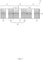
- FIG. 3 is a view for explaining a coating step and a first cutting step in a method for manufacturing an electrode according to an embodiment of the present invention.
- a method for manufacturing an electrode according to the present invention includes a step of preparing a collector 20 coated with an active material.
- a coating step of applying an electrode active material 30 to the collector 20 is performed.
- the electrode active material 30 may be applied on one surface or both surfaces of the collector 20.
- An initial electrode 10 is primarily manufactured through the coating step.
- the electrode active material may be applied to the collector so that the initial electrode 10 includes a coating portion that is an area coated with the electrode active material and a non-coating portion that is an area which is not coated with the electrode active material.
- the electrode active material may be a positive electrode or a negative electrode.
- the initial electrode may include the non-coating portion 50 that is an area which is not coated with the electrode active material 30.
- the electrode active material 30 may be applied to the collector 20 so that the coating portions 40 that are areas coated with the electrode active material 30 are spaced apart from each other by the non-coating portion 50.
- the electrode active material 30 may be applied to the collector 20 so that the coating portions 40 have the same length.
- the electrode active material 30 may be applied to the collector 20 so that the coating portions 40 are repeatedly formed. That is, in the coating step, the electrode active material 30 may be applied to the collector 20 so that the coating portions 40 having the same length are repeatedly formed.
- FIG. 3 illustrates a case in which the electrode active material 30 is repeatedly applied to the collector 20 so that the coating portion 40 has a length of a+b.
- a and b may be different values.
- FIG. 3 illustrates an example of a case in which the coating portions 42a and 44a (i.e., a first coating portion and a second coating portion), each of which has a length of a+b, are repeatedly formed on the collector 20 with the non-coating portion 50 therebetween.
- the 'length' described above does not mean that a length of the coating portion in a longitudinal direction, but means a length of the coating portion in a direction in which the electrode active material is applied in the coating step.
- FIG. 4 is a plan view for explaining a coating step and a first cutting step in a method for manufacturing an electrode according to another embodiment of the present invention and illustrates an example of a case in which the coating portions 42b and 46b (i.e., a first coating portion and a third coating portion), each of which has a length of a+b, are repeatedly formed on the collector 20 with the non-coating portion 50 and the coating portion 44b (i.e., the second coating portion) having a length of b+b therebetween.
- the coating portions 42b and 46b i.e., a first coating portion and a third coating portion
- the electrode active material may be applied to outer portions of the collector to form coating portions having different lengths from the lengths described above. That is, referring to FIGS. 3 and 4 , in the coating step, the electrode active material may be applied to one outer portion or both outer portions of the collector 20 to form outer coating portions 48 and 49 having different lengths of a+b or b+b.
- each of the outer coating portions 48 and 49 may have a length less than that of each of other coating portions 42, 44, and 46.
- FIGS. 3 and 4 illustrate a case in which outer coating portions 48 and 49, each of which has a length of a, are formed on both outer portions of the collector 20.
- the electrode active material 30 may be applied to the collector 20 so that the non-coating portion 50 having same size are repeatedly formed as the coating portions 40 having same size are repeatedly formed.
- FIGS. 3 and 4 illustrate a first cutting line that is a line for cutting the initial electrode 10 in the first cutting step.
- FIGS. 3 and 4 illustrate a case in which the first cutting line 60 in the first cutting step is defined in a direction perpendicular to that in which the electrode active material 30 is applied in the coating step.
- the first cutting line 60 may be defined at a different angle with respect to the direction in which the electrode active material 30 is applied in the coating step.
- the first cutting line 60 may be defined in parallel to the direction in which the electrode active material 30 is applied in the coating step.
- the initial electrode 10 is divided into a plurality of middle-stage electrodes 12.
- the initial electrode may be cut so that at least one of the plurality of middle-stage electrodes 12 has a length different from those of the other middle-stage electrodes 12.
- the middle-stage electrodes 12 may include a non-coating portion 50 and two coating portions spaced apart from each other by the non-coating portion 50.
- the coating portions within one middle-stage electrode 12 may have the same length.
- the a and b may have different values.
- the middle-stage electrodes 12 may be divided into two or more groups according to a length of the coating portion 40.
- FIGS. 3 and 4 illustrate a case in which the middle-stage electrodes 12 are divided into two groups according to a length of the coating portion 40.
- the middle-stage electrodes may be divided into three or more groups according to a length of the coating portion 40.
- the coating portions of the middle-stage electrodes 12 of the groups may have different lengths.
- FIGS. 3 and 4 illustrate a case in which the coating portions of the middle-stage electrodes 12 of the groups have different lengths of a and b.
- An arranged order of the middle-stage electrodes 12 of the groups after the first cutting step is performed may be different according to the coating step. That is, as illustrated in FIG. 3 , in the coating step, when the coating portions 42a and 44a (i.e., the first coating portion and the second coating portion), each of which has a length of a+b are repeatedly formed on the collector 20 with the non-coating portion 50 therebetween, the initial electrode 10 may be divided into the middle-stage electrode belonging to a first group/the middle-stage electrode belonging to a second group/the middle-stage electrode belonging to the first group after the first cutting step is performed. Alternatively, as illustrated in FIG.
- the initial electrode may be divided into the middle-stage electrode belonging to a first group/the middle-stage electrode belonging to a second group/the middle-stage electrode belonging to a second group/the middle-stage electrode belonging to the first group after the first cutting step is performed.
- a second cutting step in which the middle-stage electrode is cut to manufacture a final electrode to be used for manufacturing the electrode assembly may be performed. That is, in the coating step according to an embodiment and the other embodiment of the present invention, the first cutting step of manufacturing the middle-stage electrode from the initial electrode coated with the electrode active material on the collector and the second cutting step of manufacturing the final electrode from the middle-stage electrode may be performed to manufacture an electrode assembly having a stepped portion.
- FIG. 5 is a view for explaining the second cutting step in the methods for manufacturing the electrode according to an embodiment and another embodiment of the present invention.
- the middle-stage electrode 12 illustrated in FIG. 5 may be the middle-stage electrode manufactured from the initial electrode in the first cutting step, and thus, the middle-stage electrode 12 illustrated in FIG. 5 may have a length of a or b.
- FIG. 5 illustrates a second cutting line 70 that is a line for cutting the middle-stage electrode 12 in the second cutting line like the first cutting line.
- the second cutting line 70 may be perpendicular to the first cutting line.
- the present invention is not limited thereto.
- the second cutting line may have a predetermined angle with respect to the first cutting line.
- the second cutting step may include a step of cutting a portion of the non-coating portion of the middle-stage electrode 12 to manufacture the final electrode having an electrode tab. That is, as illustrated in FIG. 5 , the second cutting step may include a step of cutting a portion of the non-coating portion so that the portion of the non-coating portion becomes to the electrode tab 16 of the electrode 14. A plurality of final electrodes 14 may be manufactured from the middle-stage electrode 12 through the second cutting step.
- an apparatus for manufacturing an electrode according to an embodiment of the present invention will be described.
- An apparatus for manufacturing an electrode according to an embodiment of the present invention may includes: a coating unit for applying an electrode active material to one surface or both surfaces of a collector to manufacture an initial electrode; and a first cutting unit for cutting the initial electrode coated with the electrode active material to manufacture a plurality of middle-stage electrodes.
- the initial electrode may be cut so that at least one of the plurality of middle-stage electrodes has a length different from those of the other middle-stage electrodes.
- the middle-stage electrode may include a coating portion that is an area coated with the electrode active material and a non-coating portion that is an area which is not coated with the electrode active material so that the coating portions are spaced apart from each other, and, the coating portions within the middle-stage electrode may have the same length by the coating unit and the first cutting unit.
- the middle-stage electrode may be divided into two or more groups according to lengths of the coating portions.
- the coating portions of the middle-stage electrodes of the groups may have lengths different from each other.
- the electrode active material may be applied to the collector so that the initial electrode includes the non-coating portion that is the area which is not coated with the electrode active material and the coating portions that are areas coated with the electrode active material and spaced apart from each other. Also, the coating unit may apply the electrode active material so that the coating portions having the same length are repeatedly disposed.
- the apparatus for manufacturing the electrode according to an embodiment of the present invention may further include a second cutting unit for cutting the middle-stage electrode to manufacture a final electrode.
- a cutting direction of the second cutting unit may be perpendicular to that of the first cutting unit.
- the second cutting unit may cut a portion of the non-coating portion of the middle-stage electrode so that the final electrode includes an electrode tab.
Landscapes
- Chemical & Material Sciences (AREA)
- Engineering & Computer Science (AREA)
- Chemical Kinetics & Catalysis (AREA)
- Electrochemistry (AREA)
- General Chemical & Material Sciences (AREA)
- Manufacturing & Machinery (AREA)
- Materials Engineering (AREA)
- Battery Electrode And Active Subsutance (AREA)
Abstract
Description
- The present application claims the benefit of the priority of Korean Patent Application No.
10-2016-0073180, filed on June 13, 2016 - The present invention relates an apparatus and method for manufacturing an electrode, and more particularly, to an apparatus and method for manufacturing an electrode, which is capable of improving productivity of the electrode in comparison with the related art.
- As a device, on which a secondary battery is mounted, and a shape of the device are varied, a shape required for an electrode assembly constituting the secondary battery is also becoming various. To meet such a trend, studies for developing the electrode assembly having various shapes have been actively conducted.
- There are various methods for manufacturing the electrode assembly having various shapes, but as one example, there is a method for manufacturing an electrode assembly having a stepped portion by stacking electrode units having different areas. This is a method for manufacturing an electrode assembly, in which an electrode unit including an electrode and a separator is manufactured. Here, various kinds of electrode units having different areas and separators are manufactured and then stacked to manufacture the electrode assembly having the stepped portion. To manufacture the electrode assembly through the above-described method, it is necessary to manufacture electrodes having different areas.
-
FIG. 1 is a view illustrating a method for manufacturing an electrode having a first length a according to the related art, andFIG. 2 is a view illustrating a method for manufacturing an electrode having a second length b according to the related art. - Referring to
FIGS. 1 and2 , prior to the manufacturing of electrodes having lengths (i.e., areas) different from each other, aninitial electrode 1 is manufactured by applying an electrodeactive material 3 to acollector 2.FIGS. 1 and2 illustrate a process of manufacturing two initial electrodes so as to manufacture two kinds of electrodes. Here, theinitial electrode 1 includes acoating portion 4 that is an area coated with an electrodeactive material 3 and anon-coating portion 5 that is an area which is not coated with the electrodeactive material 3. - Thereafter, the
initial electrodes 1 are cut along cutting lines 6 to manufacture electrodes having the same length. Here, to manufacture the electrodes having different lengths, the initial electrodes are manufactured with different lengths.FIGS. 1 and2 illustrate a process of manufacturing electrodes having lengths a and b by cutting theinitial electrodes 1. - However, according to the related art, since the electrodes having different areas are respectively manufactured through different processes, productivity may be deteriorated. That is, for example, when two kinds of electrodes having different areas are required, there is a problem in that the productivity of the electrodes is deteriorated because two processes are also required to manufacture the electrodes. Also, to manufacture the electrodes having different areas, there is a problem in that equipment and costs required for production of the electrodes also increase due to different processes.
- Therefore, an object of the present invention is to improve productivity of electrodes by manufacturing the electrodes having different areas through one process and reduce equipment and costs required for production of the electrodes.
- According to an aspect of the present invention so at to achieve the above object, a method for manufacturing an electrode includes: a step of preparing a collector; a coating step of applying an electrode active material to one surface or both surfaces of the collector to manufacture an initial electrode; and a first cutting step of cutting the initial electrode coated with the electrode active material to manufacture a plurality of middle-stage electrodes, wherein, in the first cutting step, the initial electrode is cut so that at least one of the plurality of middle-stage electrodes has a length different from those of the other middle-stage electrodes.
- Each of the middle-stage electrodes may include a coating portion that is an area coated with the electrode active material and a non-coating portion that is an area which is not coated with the electrode active material, and the coating portions may be spaced apart from each other.
- The coating portion within the middle-stage electrodes may have the same length.
- The plurality of middle-stage electrodes may be divided into two or more groups according to lengths of the coating portions, and the coating portions of the middle-stage electrodes of the groups may have lengths different from each other.
- In the coating step, the electrode active material may be applied so that the initial electrode includes the non-coating portion that is the area which is not coated with the electrode active material and the coating portions that are areas coated with the electrode active material and spaced apart from each other, and the electrode active material may be applied so that the coating portions having the same length are repeatedly disposed.
- The method may further include a second cutting step of cutting the middle-stage electrode to manufacture a final electrode.
- A cutting direction in the first cutting step may be perpendicular to that in the second cutting step.
- In the second cutting step, a portion of the non-coating portion of the middle-stage electrode may be cut so that the final electrode includes an electrode tab.
- According to another aspect of the present invention so at to achieve the above object, an apparatus for manufacturing an electrode includes: a coating unit for applying an electrode active material to one surface or both surfaces of a collector to manufacture an initial electrode; and a first cutting unit for cutting the initial electrode coated with the electrode active material to manufacture a plurality of middle-stage electrodes, wherein, in the first cutting unit, the initial electrode is cut so that at least one of the plurality of middle-stage electrodes has a length different from those of the other middle-stage electrodes.
- Each of the middle-stage electrode may include a coating portion that is an area coated with the electrode active material and a non-coating portion that is an area which is not coated with the electrode active material, wherein the coating portions may be spaced apart from each other.
- The coating portions within the middle-stage electrode may have the same length.
- The plurality of middle-stage electrodes may be divided into two or more groups according to lengths of the coating portions, and the coating portions of the middle-stage electrode of the groups may have lengths different from each other.
- In the coating unit, the electrode active material may be applied so that the initial electrode includes the non-coating portion that is the area which is not coated with the electrode active material and the coating portions that are areas coated with the electrode active material and spaced apart from each other, and the electrode active material may be applied so that the coating portions having the same length are repeatedly disposed.
- The apparatus may further include a second cutting unit of cutting the middle-stage electrode to manufacture a final electrode.
- A cutting direction of the first cutting unit may be perpendicular to that of the second cutting unit.
- In the second cutting unit, a portion of the non-coating portion of the middle-stage electrode may be cut so that the final electrode includes an electrode tab.
- According to the present invention, since the electrodes having different areas are manufactured through one process, the productivity of the electrodes may be improved, and also, the equipment and costs required for the production of the electrodes may be reduced.
-
-
FIG. 1 is a plan view illustrating a method for manufacturing an electrode having a first length according to a related art. -
FIG. 2 is a plan view illustrating a method for manufacturing an electrode having a second length according to the related art. -
FIG. 3 is a plan view for explaining a coating step and a first cutting step in a method for manufacturing an electrode according to an embodiment of the present invention. -
FIG. 4 is a plan view for explaining a coating step and a first cutting step in a method for manufacturing an electrode according to another embodiment of the present invention. -
FIG. 5 is a plan view for explaining a second cutting step in the methods for manufacturing an electrode according to an embodiment and another embodiment of the present invention. - Hereinafter, an apparatus and method for manufacturing an electrode according to an embodiment and another embodiment of the present invention will be described with reference to the accompanying drawings.
-
FIG. 3 is a view for explaining a coating step and a first cutting step in a method for manufacturing an electrode according to an embodiment of the present invention. - A method for manufacturing an electrode according to the present invention includes a step of preparing a
collector 20 coated with an active material. - When the
collector 20 is prepared, a coating step of applying an electrodeactive material 30 to thecollector 20 is performed. In the coating step, the electrodeactive material 30 may be applied on one surface or both surfaces of thecollector 20. Aninitial electrode 10 is primarily manufactured through the coating step. - Here, in the coating step, the electrode active material may be applied to the collector so that the
initial electrode 10 includes a coating portion that is an area coated with the electrode active material and a non-coating portion that is an area which is not coated with the electrode active material. The electrode active material may be a positive electrode or a negative electrode. - That is, referring to
FIG. 3 , in the coating step, the initial electrode may include thenon-coating portion 50 that is an area which is not coated with the electrodeactive material 30. Thus, the electrodeactive material 30 may be applied to thecollector 20 so that thecoating portions 40 that are areas coated with the electrodeactive material 30 are spaced apart from each other by thenon-coating portion 50. - Also, in the coating step, the electrode
active material 30 may be applied to thecollector 20 so that thecoating portions 40 have the same length. Alternatively, the electrodeactive material 30 may be applied to thecollector 20 so that thecoating portions 40 are repeatedly formed. That is, in the coating step, the electrodeactive material 30 may be applied to thecollector 20 so that thecoating portions 40 having the same length are repeatedly formed.FIG. 3 illustrates a case in which the electrodeactive material 30 is repeatedly applied to thecollector 20 so that thecoating portion 40 has a length of a+b. Here, a and b may be different values. - In this specification, 'applying the electrode active material to the collector so that the coating portions having the same length are repeatedly formed' means that the coating portions having the same length are repeatedly formed on at least a portion of the collector and does not mean that only the coating portions having the same length are formed on the collector.
FIG. 3 illustrates an example of a case in which thecoating portions collector 20 with thenon-coating portion 50 therebetween. - Here, the 'length' described above does not mean that a length of the coating portion in a longitudinal direction, but means a length of the coating portion in a direction in which the electrode active material is applied in the coating step.
-
FIG. 4 is a plan view for explaining a coating step and a first cutting step in a method for manufacturing an electrode according to another embodiment of the present invention and illustrates an example of a case in which thecoating portions collector 20 with thenon-coating portion 50 and thecoating portion 44b (i.e., the second coating portion) having a length of b+b therebetween. - Also, in the coating step, the electrode active material may be applied to outer portions of the collector to form coating portions having different lengths from the lengths described above. That is, referring to
FIGS. 3 and4 , in the coating step, the electrode active material may be applied to one outer portion or both outer portions of thecollector 20 to formouter coating portions outer coating portions FIGS. 3 and4 illustrate a case in whichouter coating portions collector 20. - In the coating step, the electrode
active material 30 may be applied to thecollector 20 so that thenon-coating portion 50 having same size are repeatedly formed as thecoating portions 40 having same size are repeatedly formed. - When the coating step is completed, a first cutting step of producing a middle-
stage electrode 12, which is primarily processed, by cutting theinitial electrode 10 is performed.FIGS. 3 and4 illustrate a first cutting line that is a line for cutting theinitial electrode 10 in the first cutting step.FIGS. 3 and4 illustrate a case in which thefirst cutting line 60 in the first cutting step is defined in a direction perpendicular to that in which the electrodeactive material 30 is applied in the coating step. However, on the other hand, in the first cutting step, thefirst cutting line 60 may be defined at a different angle with respect to the direction in which the electrodeactive material 30 is applied in the coating step. Alternatively, in the first cutting step, thefirst cutting line 60 may be defined in parallel to the direction in which the electrodeactive material 30 is applied in the coating step. In the first cutting step, theinitial electrode 10 is divided into a plurality of middle-stage electrodes 12. - Here, in the first cutting step, the initial electrode may be cut so that at least one of the plurality of middle-
stage electrodes 12 has a length different from those of the other middle-stage electrodes 12. Also, in the first cutting step, the middle-stage electrodes 12 may include anon-coating portion 50 and two coating portions spaced apart from each other by thenon-coating portion 50. Here, the coating portions within one middle-stage electrode 12 may have the same length.FIGS. 3 and4 illustrate examples of the above-described cases, i.e., the middle-stage electrode 12 including the coating portion having a length of a/the non-coating portion/the coating portion having a length of a and the middle-stage electrode 12 including the coating portion having a length of b/the non-coating portion/the coating portion having a length of b. As described above, the a and b may have different values. - In the coating step and the first cutting step, the middle-
stage electrodes 12 may be divided into two or more groups according to a length of thecoating portion 40.FIGS. 3 and4 illustrate a case in which the middle-stage electrodes 12 are divided into two groups according to a length of thecoating portion 40. However, although not shown, in the coating step and the first cutting step, the middle-stage electrodes may be divided into three or more groups according to a length of thecoating portion 40. Here, since the middle-stage electrodes 12 are divided into two or more groups according to a length of thecoating portion 40, the coating portions of the middle-stage electrodes 12 of the groups may have different lengths.FIGS. 3 and4 illustrate a case in which the coating portions of the middle-stage electrodes 12 of the groups have different lengths of a and b. - An arranged order of the middle-
stage electrodes 12 of the groups after the first cutting step is performed may be different according to the coating step. That is, as illustrated inFIG. 3 , in the coating step, when thecoating portions collector 20 with thenon-coating portion 50 therebetween, theinitial electrode 10 may be divided into the middle-stage electrode belonging to a first group/the middle-stage electrode belonging to a second group/the middle-stage electrode belonging to the first group after the first cutting step is performed. Alternatively, as illustrated inFIG. 4 , in the coating step, when thecoating portions collector 20 with thenon-coating portion 50 and thecoating portion 44b (i.e., the second coating portion) having a length of b+b therebetween, the initial electrode may be divided into the middle-stage electrode belonging to a first group/the middle-stage electrode belonging to a second group/the middle-stage electrode belonging to a second group/the middle-stage electrode belonging to the first group after the first cutting step is performed. - When the first cutting step is completed, a second cutting step in which the middle-stage electrode is cut to manufacture a final electrode to be used for manufacturing the electrode assembly may be performed. That is, in the coating step according to an embodiment and the other embodiment of the present invention, the first cutting step of manufacturing the middle-stage electrode from the initial electrode coated with the electrode active material on the collector and the second cutting step of manufacturing the final electrode from the middle-stage electrode may be performed to manufacture an electrode assembly having a stepped portion.
-
FIG. 5 is a view for explaining the second cutting step in the methods for manufacturing the electrode according to an embodiment and another embodiment of the present invention. - The middle-
stage electrode 12 illustrated inFIG. 5 may be the middle-stage electrode manufactured from the initial electrode in the first cutting step, and thus, the middle-stage electrode 12 illustrated inFIG. 5 may have a length of a or b. -
FIG. 5 illustrates asecond cutting line 70 that is a line for cutting the middle-stage electrode 12 in the second cutting line like the first cutting line. Here, thesecond cutting line 70 may be perpendicular to the first cutting line. However, the present invention is not limited thereto. For example, the second cutting line may have a predetermined angle with respect to the first cutting line. - The second cutting step may include a step of cutting a portion of the non-coating portion of the middle-
stage electrode 12 to manufacture the final electrode having an electrode tab. That is, as illustrated inFIG. 5 , the second cutting step may include a step of cutting a portion of the non-coating portion so that the portion of the non-coating portion becomes to theelectrode tab 16 of theelectrode 14. A plurality offinal electrodes 14 may be manufactured from the middle-stage electrode 12 through the second cutting step. Hereinafter, an apparatus for manufacturing an electrode according to an embodiment of the present invention will be described. - An apparatus for manufacturing an electrode according to an embodiment of the present invention may includes: a coating unit for applying an electrode active material to one surface or both surfaces of a collector to manufacture an initial electrode; and a first cutting unit for cutting the initial electrode coated with the electrode active material to manufacture a plurality of middle-stage electrodes. Here, in the first cutting unit, the initial electrode may be cut so that at least one of the plurality of middle-stage electrodes has a length different from those of the other middle-stage electrodes.
- Also, in the coating unit and the first cutting unit, the middle-stage electrode may include a coating portion that is an area coated with the electrode active material and a non-coating portion that is an area which is not coated with the electrode active material so that the coating portions are spaced apart from each other, and, the coating portions within the middle-stage electrode may have the same length by the coating unit and the first cutting unit.
- In the coating unit and the first cutting unit, the middle-stage electrode may be divided into two or more groups according to lengths of the coating portions. Here, the coating portions of the middle-stage electrodes of the groups may have lengths different from each other.
- In the coating unit, the electrode active material may be applied to the collector so that the initial electrode includes the non-coating portion that is the area which is not coated with the electrode active material and the coating portions that are areas coated with the electrode active material and spaced apart from each other. Also, the coating unit may apply the electrode active material so that the coating portions having the same length are repeatedly disposed.
- The apparatus for manufacturing the electrode according to an embodiment of the present invention may further include a second cutting unit for cutting the middle-stage electrode to manufacture a final electrode. Here, a cutting direction of the second cutting unit may be perpendicular to that of the first cutting unit.
- Also, the second cutting unit may cut a portion of the non-coating portion of the middle-stage electrode so that the final electrode includes an electrode tab.
- While the embodiments of the present invention have been described with reference to the specific embodiments, it will be apparent to those skilled in the art that various changes and modifications may be made without departing from the spirit and scope of the invention as defined in the following claims.
Claims (16)
- A method for manufacturing an electrode, the method comprising:a step of preparing a collector;a coating step of applying an electrode active material to one surface or both surfaces of the collector to manufacture an initial electrode; anda first cutting step of cutting the initial electrode coated with the electrode active material to manufacture a plurality of middle-stage electrodes,wherein, in the first cutting step, the initial electrode is cut so that at least one of the plurality of middle-stage electrodes has a length different from those of the other middle-stage electrodes.
- The method of claim 1, wherein each of the middle-stage electrodes comprises a coating portion that is an area coated with the electrode active material and a non-coating portion that is an area which is not coated with the electrode active material, and
the coating portions are spaced apart from each other. - The method of claim 2, wherein the coating portion within the middle-stage electrodes have the same length.
- The method of claim 2, wherein the plurality of middle-stage electrodes are divided into two or more groups according to lengths of the coating portions, and
the coating portions of the middle-stage electrodes of the groups have lengths different from each other. - The method of claim 1, wherein, in the coating step, the electrode active material is applied so that the initial electrode comprises the non-coating portion that is the area which is not coated with the electrode active material and the coating portions that are areas coated with the electrode active material and spaced apart from each other, and
the electrode active material is applied so that the coating portions having the same length are repeatedly disposed. - The method of claim 1, further comprising a second cutting step of cutting the middle-stage electrode to manufacture a final electrode.
- The method of claim 6, wherein a cutting direction in the first cutting step is perpendicular to that in the second cutting step.
- The method of claim 6, wherein, in the second cutting step, a portion of the non-coating portion of the middle-stage electrode is cut so that the final electrode comprises an electrode tab.
- An apparatus for manufacturing an electrode, the apparatus comprising:a coating unit for applying an electrode active material to one surface or both surfaces of a collector to manufacture an initial electrode; anda first cutting unit for cutting the initial electrode coated with the electrode active material to manufacture a plurality of middle-stage electrodes,wherein, in the first cutting unit, the initial electrode is cut so that at least one of the plurality of middle-stage electrodes has a length different from those of the other middle-stage electrodes.
- The apparatus of claim 9, wherein each of the middle-stage electrode comprises a coating portion that is an area coated with the electrode active material and a non-coating portion that is an area which is not coated with the electrode active material,
wherein the coating portions are spaced apart from each other. - The apparatus of claim 10, wherein the coating portions within the middle-stage electrode have the same length.
- The apparatus of claim 10, wherein the plurality of middle-stage electrodes are divided into two or more groups according to lengths of the coating portions, and
the coating portions of the middle-stage electrode of the groups have lengths different from each other. - The apparatus of claim 9, wherein, in the coating unit, the electrode active material is applied so that the initial electrode comprises the non-coating portion that is the area which is not coated with the electrode active material and the coating portions that are areas coated with the electrode active material and spaced apart from each other, and
the electrode active material is applied so that the coating portions having the same length are repeatedly disposed. - The apparatus of claim 9, further comprising a second cutting unit of cutting the middle-stage electrode to manufacture a final electrode.
- The apparatus of claim 14, wherein a cutting direction of the first cutting unit is perpendicular to that of the second cutting unit.
- The apparatus of claim 14, wherein, in the second cutting unit, a portion of the non-coating portion of the middle-stage electrode is cut so that the final electrode comprises an electrode tab.
Applications Claiming Priority (2)
| Application Number | Priority Date | Filing Date | Title |
|---|---|---|---|
| KR1020160073180A KR101998194B1 (en) | 2016-06-13 | 2016-06-13 | Device and method of manufacturing electrode |
| PCT/KR2017/002664 WO2017217640A1 (en) | 2016-06-13 | 2017-03-13 | Electrode manufacturing apparatus and method |
Publications (3)
| Publication Number | Publication Date |
|---|---|
| EP3340347A1 true EP3340347A1 (en) | 2018-06-27 |
| EP3340347A4 EP3340347A4 (en) | 2018-08-08 |
| EP3340347B1 EP3340347B1 (en) | 2020-02-19 |
Family
ID=60663185
Family Applications (1)
| Application Number | Title | Priority Date | Filing Date |
|---|---|---|---|
| EP17813465.6A Active EP3340347B1 (en) | 2016-06-13 | 2017-03-13 | Apparatus and method for manufacturing electrode |
Country Status (5)
| Country | Link |
|---|---|
| US (1) | US10396345B2 (en) |
| EP (1) | EP3340347B1 (en) |
| KR (1) | KR101998194B1 (en) |
| CN (1) | CN108028353B (en) |
| WO (1) | WO2017217640A1 (en) |
Families Citing this family (9)
| Publication number | Priority date | Publication date | Assignee | Title |
|---|---|---|---|---|
| KR102294860B1 (en) * | 2018-01-19 | 2021-08-30 | 주식회사 엘지에너지솔루션 | Method of manufacturing electrode |
| KR102509113B1 (en) | 2018-03-20 | 2023-03-09 | 주식회사 엘지에너지솔루션 | Method for Preparing Anode and Anode Prepared Therefrom |
| CN108565387A (en) * | 2018-03-21 | 2018-09-21 | 中航锂电技术研究院有限公司 | A kind of lithium ion battery cell lug laser formation technique |
| CN108520940A (en) * | 2018-04-20 | 2018-09-11 | 桑顿新能源科技有限公司 | A kind of coating process suitable for lithium battery production |
| CN109585782B (en) * | 2018-10-16 | 2022-05-24 | 中创新航科技股份有限公司 | Method for simultaneously producing multiple types of lithium ion battery pole pieces and extrusion coating device |
| CN111403682A (en) * | 2020-04-17 | 2020-07-10 | 时代上汽动力电池有限公司 | Pole piece forming process |
| KR102874429B1 (en) * | 2020-07-10 | 2025-10-21 | 주식회사 엘지에너지솔루션 | The Electrode Assembly |
| CN112635704A (en) * | 2020-12-28 | 2021-04-09 | 蜂巢能源科技有限公司 | Pole piece and pole piece coating method |
| CN114700616A (en) * | 2022-06-06 | 2022-07-05 | 苏州宇量电池有限公司 | Laser dislocation die cutting method of pole piece, pole piece and battery |
Family Cites Families (15)
| Publication number | Priority date | Publication date | Assignee | Title |
|---|---|---|---|---|
| JP4784043B2 (en) | 2004-01-28 | 2011-09-28 | 株式会社Ihi | Battery electrode plate and method of manufacturing battery electrode plate |
| KR20080058772A (en) * | 2006-12-22 | 2008-06-26 | 에스케이에너지 주식회사 | Manufacturing Method of Battery Electrode |
| KR101420476B1 (en) * | 2008-09-02 | 2014-07-16 | 도요타지도샤가부시키가이샤 | Electrode sheet manufacturing method, and apparatus therefor |
| DE102008053009A1 (en) * | 2008-10-23 | 2010-04-29 | Li-Tec Battery Gmbh | Electrodes for a galvanic-based electrical device, such as lithium-ion cells, and methods of making same |
| CN102428600B (en) * | 2009-05-20 | 2014-07-09 | Nec能源元器件株式会社 | Laminated secondary battery, and method for manufacturing the laminated secondary battery |
| KR101152515B1 (en) * | 2009-12-17 | 2012-06-01 | 삼성에스디아이 주식회사 | Electrode assembly and secondary battery using the same |
| KR101292199B1 (en) * | 2010-04-01 | 2013-08-05 | 주식회사 엘지화학 | Electrode Assembly of Novel Structure and Process for Preparation of the Same |
| JP5435131B2 (en) * | 2010-06-28 | 2014-03-05 | 株式会社村田製作所 | Electric storage device and manufacturing method thereof |
| KR101175031B1 (en) * | 2010-12-30 | 2012-08-17 | 삼성에스디아이 주식회사 | Method of fabricating electrode plate and electrode plate fabricated by the same method |
| KR101599490B1 (en) * | 2012-02-07 | 2016-03-03 | 주식회사 엘지화학 | Method of manufacturing electrode plate for secondary battery, electrode plate for secondary battery and secondary battery manufactured using the same |
| KR101393530B1 (en) * | 2012-11-21 | 2014-05-12 | 주식회사 엘지화학 | Electrode sheet including notching portion |
| KR101610431B1 (en) * | 2012-11-30 | 2016-04-07 | 주식회사 엘지화학 | Electrode assembly of jelly roll type and secondary battery comprising the same |
| JP5964253B2 (en) * | 2013-01-18 | 2016-08-03 | オートモーティブエナジーサプライ株式会社 | Manufacturing method of electrode sheet for secondary battery and coating apparatus used therefor |
| KR101719026B1 (en) * | 2013-08-30 | 2017-03-22 | 주식회사 엘지화학 | Method for manufacturing electrode plate and electrode plate using the same and secondary battery |
| JP6572204B2 (en) * | 2014-02-28 | 2019-09-04 | 株式会社エンビジョンAescエナジーデバイス | Secondary battery and manufacturing method thereof |
-
2016
- 2016-06-13 KR KR1020160073180A patent/KR101998194B1/en active Active
-
2017
- 2017-03-13 US US15/758,086 patent/US10396345B2/en active Active
- 2017-03-13 WO PCT/KR2017/002664 patent/WO2017217640A1/en not_active Ceased
- 2017-03-13 EP EP17813465.6A patent/EP3340347B1/en active Active
- 2017-03-13 CN CN201780003256.XA patent/CN108028353B/en active Active
Also Published As
| Publication number | Publication date |
|---|---|
| KR20170140635A (en) | 2017-12-21 |
| US10396345B2 (en) | 2019-08-27 |
| CN108028353B (en) | 2021-05-07 |
| KR101998194B1 (en) | 2019-07-09 |
| CN108028353A (en) | 2018-05-11 |
| WO2017217640A1 (en) | 2017-12-21 |
| EP3340347B1 (en) | 2020-02-19 |
| US20180254472A1 (en) | 2018-09-06 |
| EP3340347A4 (en) | 2018-08-08 |
Similar Documents
| Publication | Publication Date | Title |
|---|---|---|
| EP3340347B1 (en) | Apparatus and method for manufacturing electrode | |
| JP2011204613A (en) | Electrode plate manufacturing device | |
| US9502712B2 (en) | Method of manufacturing battery electrode | |
| EP4023402B1 (en) | Notching apparatus | |
| US10501863B2 (en) | Forming method and formed article | |
| EP4234767A3 (en) | Electroforming assemblies for electrical machines | |
| KR102256482B1 (en) | Method of manufacturing electrode stack | |
| KR102781215B1 (en) | Method for Manufacturing Electrode Comprising Folding Portion and Electrode Sheet Having Folding Portion | |
| KR102781206B1 (en) | Method for Manufacturing Electrode Comprising Folding Portion and Electrode Sheet Comprising the Same | |
| US10236753B2 (en) | Method of manufacturing assembled conductor and electric motor | |
| KR102497265B1 (en) | method and device for manufacturing electrode | |
| KR20180115152A (en) | Unit electrode of battery solving unbalance residual stress and lithium ion polymer battery including the same | |
| JP2016019413A (en) | Processing method of laminate material | |
| JP2024156256A (en) | Manufacturing method for square case | |
| KR102933475B1 (en) | Electrode Manufacturing Method and Electrode Manufacturing Apparatus Used Therefor | |
| CN109841907B (en) | Manufacturing method of wound electrode body | |
| WO2017018347A1 (en) | Electrode sheet production method | |
| KR20180041529A (en) | Electrode assembly and method of manumfacturing the same | |
| CN107708888A (en) | The manufacture method and packing ring of packing ring | |
| JP2013191384A (en) | Battery electrode plate manufacturing method and battery electrode plate manufacturing mold | |
| EP3993086B1 (en) | Electrode for secondary battery and method for manufacturing the same | |
| KR20160001048U (en) | Electrode plate for secondary battery | |
| KR102294860B1 (en) | Method of manufacturing electrode | |
| US20260112677A1 (en) | Notching device for electrode substrate for a secondary battery | |
| KR101804612B1 (en) | Secondary battery and manufacturing process for the same |
Legal Events
| Date | Code | Title | Description |
|---|---|---|---|
| STAA | Information on the status of an ep patent application or granted ep patent |
Free format text: STATUS: THE INTERNATIONAL PUBLICATION HAS BEEN MADE |
|
| PUAI | Public reference made under article 153(3) epc to a published international application that has entered the european phase |
Free format text: ORIGINAL CODE: 0009012 |
|
| STAA | Information on the status of an ep patent application or granted ep patent |
Free format text: STATUS: REQUEST FOR EXAMINATION WAS MADE |
|
| 17P | Request for examination filed |
Effective date: 20180301 |
|
| AK | Designated contracting states |
Kind code of ref document: A1 Designated state(s): AL AT BE BG CH CY CZ DE DK EE ES FI FR GB GR HR HU IE IS IT LI LT LU LV MC MK MT NL NO PL PT RO RS SE SI SK SM TR |
|
| AX | Request for extension of the european patent |
Extension state: BA ME |
|
| A4 | Supplementary search report drawn up and despatched |
Effective date: 20180706 |
|
| RIC1 | Information provided on ipc code assigned before grant |
Ipc: H01M 4/139 20100101ALI20180702BHEP Ipc: H01M 4/02 20060101ALI20180702BHEP Ipc: H01M 4/04 20060101AFI20180702BHEP |
|
| STAA | Information on the status of an ep patent application or granted ep patent |
Free format text: STATUS: EXAMINATION IS IN PROGRESS |
|
| 17Q | First examination report despatched |
Effective date: 20181128 |
|
| DAV | Request for validation of the european patent (deleted) | ||
| DAX | Request for extension of the european patent (deleted) | ||
| GRAP | Despatch of communication of intention to grant a patent |
Free format text: ORIGINAL CODE: EPIDOSNIGR1 |
|
| STAA | Information on the status of an ep patent application or granted ep patent |
Free format text: STATUS: GRANT OF PATENT IS INTENDED |
|
| INTG | Intention to grant announced |
Effective date: 20191025 |
|
| GRAS | Grant fee paid |
Free format text: ORIGINAL CODE: EPIDOSNIGR3 |
|
| GRAA | (expected) grant |
Free format text: ORIGINAL CODE: 0009210 |
|
| STAA | Information on the status of an ep patent application or granted ep patent |
Free format text: STATUS: THE PATENT HAS BEEN GRANTED |
|
| AK | Designated contracting states |
Kind code of ref document: B1 Designated state(s): AL AT BE BG CH CY CZ DE DK EE ES FI FR GB GR HR HU IE IS IT LI LT LU LV MC MK MT NL NO PL PT RO RS SE SI SK SM TR |
|
| REG | Reference to a national code |
Ref country code: CH Ref legal event code: EP |
|
| REG | Reference to a national code |
Ref country code: DE Ref legal event code: R096 Ref document number: 602017012080 Country of ref document: DE |
|
| REG | Reference to a national code |
Ref country code: AT Ref legal event code: REF Ref document number: 1235969 Country of ref document: AT Kind code of ref document: T Effective date: 20200315 |
|
| REG | Reference to a national code |
Ref country code: IE Ref legal event code: FG4D |
|
| REG | Reference to a national code |
Ref country code: NL Ref legal event code: MP Effective date: 20200219 |
|
| PG25 | Lapsed in a contracting state [announced via postgrant information from national office to epo] |
Ref country code: RS Free format text: LAPSE BECAUSE OF FAILURE TO SUBMIT A TRANSLATION OF THE DESCRIPTION OR TO PAY THE FEE WITHIN THE PRESCRIBED TIME-LIMIT Effective date: 20200219 Ref country code: NO Free format text: LAPSE BECAUSE OF FAILURE TO SUBMIT A TRANSLATION OF THE DESCRIPTION OR TO PAY THE FEE WITHIN THE PRESCRIBED TIME-LIMIT Effective date: 20200519 Ref country code: FI Free format text: LAPSE BECAUSE OF FAILURE TO SUBMIT A TRANSLATION OF THE DESCRIPTION OR TO PAY THE FEE WITHIN THE PRESCRIBED TIME-LIMIT Effective date: 20200219 |
|
| REG | Reference to a national code |
Ref country code: LT Ref legal event code: MG4D |
|
| PG25 | Lapsed in a contracting state [announced via postgrant information from national office to epo] |
Ref country code: HR Free format text: LAPSE BECAUSE OF FAILURE TO SUBMIT A TRANSLATION OF THE DESCRIPTION OR TO PAY THE FEE WITHIN THE PRESCRIBED TIME-LIMIT Effective date: 20200219 Ref country code: IS Free format text: LAPSE BECAUSE OF FAILURE TO SUBMIT A TRANSLATION OF THE DESCRIPTION OR TO PAY THE FEE WITHIN THE PRESCRIBED TIME-LIMIT Effective date: 20200619 Ref country code: SE Free format text: LAPSE BECAUSE OF FAILURE TO SUBMIT A TRANSLATION OF THE DESCRIPTION OR TO PAY THE FEE WITHIN THE PRESCRIBED TIME-LIMIT Effective date: 20200219 Ref country code: LV Free format text: LAPSE BECAUSE OF FAILURE TO SUBMIT A TRANSLATION OF THE DESCRIPTION OR TO PAY THE FEE WITHIN THE PRESCRIBED TIME-LIMIT Effective date: 20200219 Ref country code: BG Free format text: LAPSE BECAUSE OF FAILURE TO SUBMIT A TRANSLATION OF THE DESCRIPTION OR TO PAY THE FEE WITHIN THE PRESCRIBED TIME-LIMIT Effective date: 20200519 Ref country code: GR Free format text: LAPSE BECAUSE OF FAILURE TO SUBMIT A TRANSLATION OF THE DESCRIPTION OR TO PAY THE FEE WITHIN THE PRESCRIBED TIME-LIMIT Effective date: 20200520 |
|
| PG25 | Lapsed in a contracting state [announced via postgrant information from national office to epo] |
Ref country code: NL Free format text: LAPSE BECAUSE OF FAILURE TO SUBMIT A TRANSLATION OF THE DESCRIPTION OR TO PAY THE FEE WITHIN THE PRESCRIBED TIME-LIMIT Effective date: 20200219 |
|
| PG25 | Lapsed in a contracting state [announced via postgrant information from national office to epo] |
Ref country code: PT Free format text: LAPSE BECAUSE OF FAILURE TO SUBMIT A TRANSLATION OF THE DESCRIPTION OR TO PAY THE FEE WITHIN THE PRESCRIBED TIME-LIMIT Effective date: 20200712 Ref country code: RO Free format text: LAPSE BECAUSE OF FAILURE TO SUBMIT A TRANSLATION OF THE DESCRIPTION OR TO PAY THE FEE WITHIN THE PRESCRIBED TIME-LIMIT Effective date: 20200219 Ref country code: SK Free format text: LAPSE BECAUSE OF FAILURE TO SUBMIT A TRANSLATION OF THE DESCRIPTION OR TO PAY THE FEE WITHIN THE PRESCRIBED TIME-LIMIT Effective date: 20200219 Ref country code: CZ Free format text: LAPSE BECAUSE OF FAILURE TO SUBMIT A TRANSLATION OF THE DESCRIPTION OR TO PAY THE FEE WITHIN THE PRESCRIBED TIME-LIMIT Effective date: 20200219 Ref country code: LT Free format text: LAPSE BECAUSE OF FAILURE TO SUBMIT A TRANSLATION OF THE DESCRIPTION OR TO PAY THE FEE WITHIN THE PRESCRIBED TIME-LIMIT Effective date: 20200219 Ref country code: ES Free format text: LAPSE BECAUSE OF FAILURE TO SUBMIT A TRANSLATION OF THE DESCRIPTION OR TO PAY THE FEE WITHIN THE PRESCRIBED TIME-LIMIT Effective date: 20200219 Ref country code: EE Free format text: LAPSE BECAUSE OF FAILURE TO SUBMIT A TRANSLATION OF THE DESCRIPTION OR TO PAY THE FEE WITHIN THE PRESCRIBED TIME-LIMIT Effective date: 20200219 Ref country code: SM Free format text: LAPSE BECAUSE OF FAILURE TO SUBMIT A TRANSLATION OF THE DESCRIPTION OR TO PAY THE FEE WITHIN THE PRESCRIBED TIME-LIMIT Effective date: 20200219 Ref country code: DK Free format text: LAPSE BECAUSE OF FAILURE TO SUBMIT A TRANSLATION OF THE DESCRIPTION OR TO PAY THE FEE WITHIN THE PRESCRIBED TIME-LIMIT Effective date: 20200219 |
|
| REG | Reference to a national code |
Ref country code: CH Ref legal event code: PL |
|
| REG | Reference to a national code |
Ref country code: AT Ref legal event code: MK05 Ref document number: 1235969 Country of ref document: AT Kind code of ref document: T Effective date: 20200219 |
|
| REG | Reference to a national code |
Ref country code: DE Ref legal event code: R097 Ref document number: 602017012080 Country of ref document: DE |
|
| PG25 | Lapsed in a contracting state [announced via postgrant information from national office to epo] |
Ref country code: MC Free format text: LAPSE BECAUSE OF FAILURE TO SUBMIT A TRANSLATION OF THE DESCRIPTION OR TO PAY THE FEE WITHIN THE PRESCRIBED TIME-LIMIT Effective date: 20200219 |
|
| REG | Reference to a national code |
Ref country code: BE Ref legal event code: MM Effective date: 20200331 |
|
| PLBE | No opposition filed within time limit |
Free format text: ORIGINAL CODE: 0009261 |
|
| STAA | Information on the status of an ep patent application or granted ep patent |
Free format text: STATUS: NO OPPOSITION FILED WITHIN TIME LIMIT |
|
| PG25 | Lapsed in a contracting state [announced via postgrant information from national office to epo] |
Ref country code: LU Free format text: LAPSE BECAUSE OF NON-PAYMENT OF DUE FEES Effective date: 20200313 |
|
| 26N | No opposition filed |
Effective date: 20201120 |
|
| PG25 | Lapsed in a contracting state [announced via postgrant information from national office to epo] |
Ref country code: CH Free format text: LAPSE BECAUSE OF NON-PAYMENT OF DUE FEES Effective date: 20200331 Ref country code: LI Free format text: LAPSE BECAUSE OF NON-PAYMENT OF DUE FEES Effective date: 20200331 Ref country code: IE Free format text: LAPSE BECAUSE OF NON-PAYMENT OF DUE FEES Effective date: 20200313 Ref country code: IT Free format text: LAPSE BECAUSE OF FAILURE TO SUBMIT A TRANSLATION OF THE DESCRIPTION OR TO PAY THE FEE WITHIN THE PRESCRIBED TIME-LIMIT Effective date: 20200219 Ref country code: AT Free format text: LAPSE BECAUSE OF FAILURE TO SUBMIT A TRANSLATION OF THE DESCRIPTION OR TO PAY THE FEE WITHIN THE PRESCRIBED TIME-LIMIT Effective date: 20200219 |
|
| PG25 | Lapsed in a contracting state [announced via postgrant information from national office to epo] |
Ref country code: SI Free format text: LAPSE BECAUSE OF FAILURE TO SUBMIT A TRANSLATION OF THE DESCRIPTION OR TO PAY THE FEE WITHIN THE PRESCRIBED TIME-LIMIT Effective date: 20200219 Ref country code: PL Free format text: LAPSE BECAUSE OF FAILURE TO SUBMIT A TRANSLATION OF THE DESCRIPTION OR TO PAY THE FEE WITHIN THE PRESCRIBED TIME-LIMIT Effective date: 20200219 Ref country code: BE Free format text: LAPSE BECAUSE OF NON-PAYMENT OF DUE FEES Effective date: 20200331 |
|
| PG25 | Lapsed in a contracting state [announced via postgrant information from national office to epo] |
Ref country code: TR Free format text: LAPSE BECAUSE OF FAILURE TO SUBMIT A TRANSLATION OF THE DESCRIPTION OR TO PAY THE FEE WITHIN THE PRESCRIBED TIME-LIMIT Effective date: 20200219 Ref country code: MT Free format text: LAPSE BECAUSE OF FAILURE TO SUBMIT A TRANSLATION OF THE DESCRIPTION OR TO PAY THE FEE WITHIN THE PRESCRIBED TIME-LIMIT Effective date: 20200219 Ref country code: CY Free format text: LAPSE BECAUSE OF FAILURE TO SUBMIT A TRANSLATION OF THE DESCRIPTION OR TO PAY THE FEE WITHIN THE PRESCRIBED TIME-LIMIT Effective date: 20200219 |
|
| PG25 | Lapsed in a contracting state [announced via postgrant information from national office to epo] |
Ref country code: MK Free format text: LAPSE BECAUSE OF FAILURE TO SUBMIT A TRANSLATION OF THE DESCRIPTION OR TO PAY THE FEE WITHIN THE PRESCRIBED TIME-LIMIT Effective date: 20200219 Ref country code: AL Free format text: LAPSE BECAUSE OF FAILURE TO SUBMIT A TRANSLATION OF THE DESCRIPTION OR TO PAY THE FEE WITHIN THE PRESCRIBED TIME-LIMIT Effective date: 20200219 |
|
| REG | Reference to a national code |
Ref country code: DE Ref legal event code: R081 Ref document number: 602017012080 Country of ref document: DE Owner name: LG ENERGY SOLUTION, LTD., KR Free format text: FORMER OWNER: LG CHEM. LTD., SEOUL, KR |
|
| P01 | Opt-out of the competence of the unified patent court (upc) registered |
Effective date: 20230512 |
|
| REG | Reference to a national code |
Ref country code: GB Ref legal event code: 732E Free format text: REGISTERED BETWEEN 20230824 AND 20230831 |
|
| PGFP | Annual fee paid to national office [announced via postgrant information from national office to epo] |
Ref country code: GB Payment date: 20260224 Year of fee payment: 10 |
|
| PGFP | Annual fee paid to national office [announced via postgrant information from national office to epo] |
Ref country code: DE Payment date: 20260220 Year of fee payment: 10 |
|
| PGFP | Annual fee paid to national office [announced via postgrant information from national office to epo] |
Ref country code: FR Payment date: 20260224 Year of fee payment: 10 |