EP3340345A1 - Battery module - Google Patents
Battery module Download PDFInfo
- Publication number
- EP3340345A1 EP3340345A1 EP17210530.6A EP17210530A EP3340345A1 EP 3340345 A1 EP3340345 A1 EP 3340345A1 EP 17210530 A EP17210530 A EP 17210530A EP 3340345 A1 EP3340345 A1 EP 3340345A1
- Authority
- EP
- European Patent Office
- Prior art keywords
- electrode tab
- bus bar
- hole
- battery module
- plate
- Prior art date
- Legal status (The legal status is an assumption and is not a legal conclusion. Google has not performed a legal analysis and makes no representation as to the accuracy of the status listed.)
- Granted
Links
Images








Classifications
-
- H—ELECTRICITY
- H01—ELECTRIC ELEMENTS
- H01M—PROCESSES OR MEANS, e.g. BATTERIES, FOR THE DIRECT CONVERSION OF CHEMICAL ENERGY INTO ELECTRICAL ENERGY
- H01M50/00—Constructional details or processes of manufacture of the non-active parts of electrochemical cells other than fuel cells, e.g. hybrid cells
- H01M50/50—Current conducting connections for cells or batteries
- H01M50/502—Interconnectors for connecting terminals of adjacent batteries; Interconnectors for connecting cells outside a battery casing
- H01M50/514—Methods for interconnecting adjacent batteries or cells
- H01M50/516—Methods for interconnecting adjacent batteries or cells by welding, soldering or brazing
-
- H—ELECTRICITY
- H01—ELECTRIC ELEMENTS
- H01M—PROCESSES OR MEANS, e.g. BATTERIES, FOR THE DIRECT CONVERSION OF CHEMICAL ENERGY INTO ELECTRICAL ENERGY
- H01M50/00—Constructional details or processes of manufacture of the non-active parts of electrochemical cells other than fuel cells, e.g. hybrid cells
- H01M50/50—Current conducting connections for cells or batteries
- H01M50/502—Interconnectors for connecting terminals of adjacent batteries; Interconnectors for connecting cells outside a battery casing
-
- H—ELECTRICITY
- H01—ELECTRIC ELEMENTS
- H01M—PROCESSES OR MEANS, e.g. BATTERIES, FOR THE DIRECT CONVERSION OF CHEMICAL ENERGY INTO ELECTRICAL ENERGY
- H01M10/00—Secondary cells; Manufacture thereof
- H01M10/04—Construction or manufacture in general
- H01M10/0413—Large-sized flat cells or batteries for motive or stationary systems with plate-like electrodes
-
- H—ELECTRICITY
- H01—ELECTRIC ELEMENTS
- H01M—PROCESSES OR MEANS, e.g. BATTERIES, FOR THE DIRECT CONVERSION OF CHEMICAL ENERGY INTO ELECTRICAL ENERGY
- H01M50/00—Constructional details or processes of manufacture of the non-active parts of electrochemical cells other than fuel cells, e.g. hybrid cells
- H01M50/20—Mountings; Secondary casings or frames; Racks, modules or packs; Suspension devices; Shock absorbers; Transport or carrying devices; Holders
- H01M50/204—Racks, modules or packs for multiple batteries or multiple cells
-
- H—ELECTRICITY
- H01—ELECTRIC ELEMENTS
- H01M—PROCESSES OR MEANS, e.g. BATTERIES, FOR THE DIRECT CONVERSION OF CHEMICAL ENERGY INTO ELECTRICAL ENERGY
- H01M50/00—Constructional details or processes of manufacture of the non-active parts of electrochemical cells other than fuel cells, e.g. hybrid cells
- H01M50/20—Mountings; Secondary casings or frames; Racks, modules or packs; Suspension devices; Shock absorbers; Transport or carrying devices; Holders
- H01M50/204—Racks, modules or packs for multiple batteries or multiple cells
- H01M50/207—Racks, modules or packs for multiple batteries or multiple cells characterised by their shape
- H01M50/209—Racks, modules or packs for multiple batteries or multiple cells characterised by their shape adapted for prismatic or rectangular cells
-
- H—ELECTRICITY
- H01—ELECTRIC ELEMENTS
- H01M—PROCESSES OR MEANS, e.g. BATTERIES, FOR THE DIRECT CONVERSION OF CHEMICAL ENERGY INTO ELECTRICAL ENERGY
- H01M50/00—Constructional details or processes of manufacture of the non-active parts of electrochemical cells other than fuel cells, e.g. hybrid cells
- H01M50/20—Mountings; Secondary casings or frames; Racks, modules or packs; Suspension devices; Shock absorbers; Transport or carrying devices; Holders
- H01M50/244—Secondary casings; Racks; Suspension devices; Carrying devices; Holders characterised by their mounting method
-
- H—ELECTRICITY
- H01—ELECTRIC ELEMENTS
- H01M—PROCESSES OR MEANS, e.g. BATTERIES, FOR THE DIRECT CONVERSION OF CHEMICAL ENERGY INTO ELECTRICAL ENERGY
- H01M50/00—Constructional details or processes of manufacture of the non-active parts of electrochemical cells other than fuel cells, e.g. hybrid cells
- H01M50/50—Current conducting connections for cells or batteries
- H01M50/502—Interconnectors for connecting terminals of adjacent batteries; Interconnectors for connecting cells outside a battery casing
- H01M50/503—Interconnectors for connecting terminals of adjacent batteries; Interconnectors for connecting cells outside a battery casing characterised by the shape of the interconnectors
-
- H—ELECTRICITY
- H01—ELECTRIC ELEMENTS
- H01M—PROCESSES OR MEANS, e.g. BATTERIES, FOR THE DIRECT CONVERSION OF CHEMICAL ENERGY INTO ELECTRICAL ENERGY
- H01M50/00—Constructional details or processes of manufacture of the non-active parts of electrochemical cells other than fuel cells, e.g. hybrid cells
- H01M50/50—Current conducting connections for cells or batteries
- H01M50/502—Interconnectors for connecting terminals of adjacent batteries; Interconnectors for connecting cells outside a battery casing
- H01M50/507—Interconnectors for connecting terminals of adjacent batteries; Interconnectors for connecting cells outside a battery casing comprising an arrangement of two or more busbars within a container structure, e.g. busbar modules
-
- H—ELECTRICITY
- H01—ELECTRIC ELEMENTS
- H01M—PROCESSES OR MEANS, e.g. BATTERIES, FOR THE DIRECT CONVERSION OF CHEMICAL ENERGY INTO ELECTRICAL ENERGY
- H01M50/00—Constructional details or processes of manufacture of the non-active parts of electrochemical cells other than fuel cells, e.g. hybrid cells
- H01M50/50—Current conducting connections for cells or batteries
- H01M50/502—Interconnectors for connecting terminals of adjacent batteries; Interconnectors for connecting cells outside a battery casing
- H01M50/509—Interconnectors for connecting terminals of adjacent batteries; Interconnectors for connecting cells outside a battery casing characterised by the type of connection, e.g. mixed connections
-
- H—ELECTRICITY
- H01—ELECTRIC ELEMENTS
- H01M—PROCESSES OR MEANS, e.g. BATTERIES, FOR THE DIRECT CONVERSION OF CHEMICAL ENERGY INTO ELECTRICAL ENERGY
- H01M50/00—Constructional details or processes of manufacture of the non-active parts of electrochemical cells other than fuel cells, e.g. hybrid cells
- H01M50/50—Current conducting connections for cells or batteries
- H01M50/502—Interconnectors for connecting terminals of adjacent batteries; Interconnectors for connecting cells outside a battery casing
- H01M50/509—Interconnectors for connecting terminals of adjacent batteries; Interconnectors for connecting cells outside a battery casing characterised by the type of connection, e.g. mixed connections
- H01M50/512—Connection only in parallel
-
- H—ELECTRICITY
- H01—ELECTRIC ELEMENTS
- H01M—PROCESSES OR MEANS, e.g. BATTERIES, FOR THE DIRECT CONVERSION OF CHEMICAL ENERGY INTO ELECTRICAL ENERGY
- H01M50/00—Constructional details or processes of manufacture of the non-active parts of electrochemical cells other than fuel cells, e.g. hybrid cells
- H01M50/50—Current conducting connections for cells or batteries
- H01M50/528—Fixed electrical connections, i.e. not intended for disconnection
-
- H—ELECTRICITY
- H01—ELECTRIC ELEMENTS
- H01M—PROCESSES OR MEANS, e.g. BATTERIES, FOR THE DIRECT CONVERSION OF CHEMICAL ENERGY INTO ELECTRICAL ENERGY
- H01M50/00—Constructional details or processes of manufacture of the non-active parts of electrochemical cells other than fuel cells, e.g. hybrid cells
- H01M50/50—Current conducting connections for cells or batteries
- H01M50/531—Electrode connections inside a battery casing
- H01M50/536—Electrode connections inside a battery casing characterised by the method of fixing the leads to the electrodes, e.g. by welding
-
- H—ELECTRICITY
- H01—ELECTRIC ELEMENTS
- H01M—PROCESSES OR MEANS, e.g. BATTERIES, FOR THE DIRECT CONVERSION OF CHEMICAL ENERGY INTO ELECTRICAL ENERGY
- H01M50/00—Constructional details or processes of manufacture of the non-active parts of electrochemical cells other than fuel cells, e.g. hybrid cells
- H01M50/50—Current conducting connections for cells or batteries
- H01M50/543—Terminals
- H01M50/552—Terminals characterised by their shape
- H01M50/553—Terminals adapted for prismatic, pouch or rectangular cells
-
- B—PERFORMING OPERATIONS; TRANSPORTING
- B23—MACHINE TOOLS; METAL-WORKING NOT OTHERWISE PROVIDED FOR
- B23K—SOLDERING OR UNSOLDERING; WELDING; CLADDING OR PLATING BY SOLDERING OR WELDING; CUTTING BY APPLYING HEAT LOCALLY, e.g. FLAME CUTTING; WORKING BY LASER BEAM
- B23K2103/00—Materials to be soldered, welded or cut
- B23K2103/08—Non-ferrous metals or alloys
- B23K2103/10—Aluminium or alloys thereof
-
- B—PERFORMING OPERATIONS; TRANSPORTING
- B23—MACHINE TOOLS; METAL-WORKING NOT OTHERWISE PROVIDED FOR
- B23K—SOLDERING OR UNSOLDERING; WELDING; CLADDING OR PLATING BY SOLDERING OR WELDING; CUTTING BY APPLYING HEAT LOCALLY, e.g. FLAME CUTTING; WORKING BY LASER BEAM
- B23K2103/00—Materials to be soldered, welded or cut
- B23K2103/08—Non-ferrous metals or alloys
- B23K2103/12—Copper or alloys thereof
-
- H—ELECTRICITY
- H01—ELECTRIC ELEMENTS
- H01M—PROCESSES OR MEANS, e.g. BATTERIES, FOR THE DIRECT CONVERSION OF CHEMICAL ENERGY INTO ELECTRICAL ENERGY
- H01M2200/00—Safety devices for primary or secondary batteries
- H01M2200/10—Temperature sensitive devices
-
- Y—GENERAL TAGGING OF NEW TECHNOLOGICAL DEVELOPMENTS; GENERAL TAGGING OF CROSS-SECTIONAL TECHNOLOGIES SPANNING OVER SEVERAL SECTIONS OF THE IPC; TECHNICAL SUBJECTS COVERED BY FORMER USPC CROSS-REFERENCE ART COLLECTIONS [XRACs] AND DIGESTS
- Y02—TECHNOLOGIES OR APPLICATIONS FOR MITIGATION OR ADAPTATION AGAINST CLIMATE CHANGE
- Y02E—REDUCTION OF GREENHOUSE GAS [GHG] EMISSIONS, RELATED TO ENERGY GENERATION, TRANSMISSION OR DISTRIBUTION
- Y02E60/00—Enabling technologies; Technologies with a potential or indirect contribution to GHG emissions mitigation
- Y02E60/10—Energy storage using batteries
-
- Y—GENERAL TAGGING OF NEW TECHNOLOGICAL DEVELOPMENTS; GENERAL TAGGING OF CROSS-SECTIONAL TECHNOLOGIES SPANNING OVER SEVERAL SECTIONS OF THE IPC; TECHNICAL SUBJECTS COVERED BY FORMER USPC CROSS-REFERENCE ART COLLECTIONS [XRACs] AND DIGESTS
- Y02—TECHNOLOGIES OR APPLICATIONS FOR MITIGATION OR ADAPTATION AGAINST CLIMATE CHANGE
- Y02P—CLIMATE CHANGE MITIGATION TECHNOLOGIES IN THE PRODUCTION OR PROCESSING OF GOODS
- Y02P70/00—Climate change mitigation technologies in the production process for final industrial or consumer products
- Y02P70/50—Manufacturing or production processes characterised by the final manufactured product
Definitions
- Exemplary embodiments of the present disclosure relate to a battery module.
- secondary batteries include a nickel-cadmium battery, a nickel-metal hydride battery, a nickel-hydrogen battery, and a lithium secondary battery.
- the lithium secondary battery typically has an operating voltage of 3.6 V or higher and can be used as a power source for portable electronic devices.
- a plurality of lithium secondary batteries connected in series can be used to power a high-output hybrid vehicle.
- Use of the lithium secondary battery has rapidly increased because its operating voltage thereof is approximately three times higher than that of the nickel-cadmium battery or the nickel-metal hydride battery.
- the lithium secondary battery has excellent energy density per unit of weight.
- a bus bar is brought into contact with the electrode tabs of battery cells for connecting a plurality of battery cells.
- a conventional bus bar is formed to have a C shape.
- Electrode tabs may be brought into contact with a C-shaped bus bar so that two or more battery cells can be electrically connected. Connecting the battery cells may require at least one of cutting and bending the electrode tabs of the battery cells.
- the cutting and bending dimensions of electrode tabs also vary. Because existing battery modules require deforming the electrode tabs for coupling the battery cells, the number of required process operations is increased, which in turn renders the manufacturing process more complicated and increases its cost.
- Embodiments of the present disclosure provide a battery module allowing the number of assembling processes to be reduced due to electrode tab processing for electrically connecting a plurality of battery cells being simplified.
- a battery module including a plurality of battery cells each including at least one electrode tab, and a bus bar in contact with the electrode tabs to electrically connect the plurality of battery cells, wherein the bus bar includes a plate in which a plurality of holes are formed, and the electrode tabs are inserted into at least a portion of the plurality of holes to electrically connect the plurality of battery cells.
- Each of the plurality of electrode tabs may be inserted into the corresponding one of the plurality of holes and fixed.
- the electrode tab may be inserted into one side of the plate and protrude to the other side of the plate.
- the electrode tab may protrude by a length of 1 to 3 mm from an outer end of the hole.
- the plate may include a protruding portion formed at a periphery of a position at which the hole is formed.
- a cross-section of the periphery of the hole may be formed to be tapered toward one side of the plate so that the electrode tab may be inserted into the hole.
- a width of an entry space into which the electrode tab enters at the one side of the plate may be reduced near the hole.
- the plate may include a tab connection portion configured to protrude from an outer periphery of the hole to an outside of the plate.
- the electrode tab and the plate may be connected to have a wobble welding shape by laser welding.
- the hole may be formed to correspond to a thickness and a length of the electrode tab.
- a sum of both gaps between the hole and the electrode tab inserted into the hole may range from 0.1 mm to 0.2 mm.
- the electrode tab may be formed in a straight line without being bent.
- At least one electrode tab includes a bent portion and a straight portion, and at least a part of the straight portion is inserted into its respective hole.
- the at least one electrode tab may include an insulating portion formed on at least a portion of the electrode tab, and the bent portion may be formed on the insulating portion.
- the battery module may further include a support plate in which a plurality of support holes corresponding to the holes are formed and the support plate may be located between the plurality of battery cells and the bus bar.
- the bent portion may be formed at the electrode tab and the bent portion may be supported to be in contact with one side of the support hole.
- the battery module may further include a fixing plate in which a plurality of bus bar exposure holes corresponding to the holes are formed and the bus bar may be located between the support plate and the fixing plate and may be fixedly supported thereby.
- a plurality of bus bars may be provided, at least two of the plurality of electrode tabs may be connected to at least one of the plurality of bus bars in parallel to form a parallel assembly, and a plurality of the parallel assemblies may be provided and connected in series or in parallel.
- a method of manufacturing a battery module including providing a plurality of battery cells stacked in parallel next to each other, each battery cell including an electrode tab, providing a bus bar comprising a plurality of holes formed at a regular interval and configured to receive the plurality of electrode tabs, positioning the bus bar adjacent to the battery cells so that the plurality of holes of the bus bar are positioned adjacent to the plurality of corresponding electrode tabs ,inserting the plurality of electrode tabs into the corresponding holes of the bus bar, and fixing the electrode tabs to the bus bar.
- the electrode tab may protrude toward the other side of the plate.
- the electrode tab may protrude by a length of 1 to 3 mm from an outer end of the hole. wherein said fixing includes welding the electrode tabs to the bus bar. wherein said welding includes laser welding of only the electrode tabs and not of the bus bar.
- the laser may be repeatedly applied to an end surface of the electrode tab in a shape of a circle, and centers of the circles may be located along an axis of a longitudinal direction of the end surface.
- the laser may be applied to the electrode tab obliquely with respect to a central axis of a longitudinal direction thereof.
- a support plate may be arranged between the plurality of battery cells and a bus bar, and the electrode tab may be positioned to pass through a support hole of the support plate.
- the bus bar may be coupled to at least a portion of the support plate and may be fixedly supported thereby.
- a fixing plate may be arranged at another side of the bus bar, and the hole may be exposed to the outside through a bus bar exposure hole of the fixing plate.
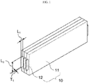
- FIG. 1 is a view illustrating a secondary battery 10 according to an embodiment of the present disclosure.
- FIG. 2 is a view illustrating a state in which a bus bar 20a is arranged on the secondary battery.
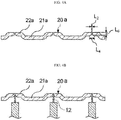
- FIGS. 3A and 3B are views illustrating the bus bar 20a.
- FIGS. 1 , 2 , 3A, and 3B references will be made to FIGS. 1 , 2 , 3A, and 3B .
- the secondary battery 10 may include a plurality of battery cells 11 and electrode tabs 12 drawn from the battery cells 11.
- the bus bar 20a may have a shape in which holes 23a (shown in FIG. 3B ) are formed in a plate 21a (shown in FIGS. 3 ).
- a plurality of holes 23a may be formed in the plate 21a, and an electrode tab 12 is welded to each of the holes 23a so that a plurality of welded battery cells 11 may be electrically connected. Since the electrode tabs 12 are inserted into the respective holes 23a, it is not necessary to deform the shape of the electrode tabs 12.
- the number of the plurality of holes 23a which are formed in the plate 21a of the bus bar 20a correspond to the number of the battery cells 11 to be connected thereto via the bus bar 20a. Therefore, the battery cells 11 may be electrically connected without changing the shape of the electrode tabs 12 regardless of the number of battery cells 11 to be connected in order to electrically connect the battery cells 11. Details of the plate 21a and the holes 23a will be described below.
- the bus bar 20a may include the plate 21a, protruding portions 22a, and the holes 23a.
- the plurality of holes 23a are formed in the plate 21a at predetermined intervals, and each may have a suitable shape and sufficient size so that the electrode tabs 12 can be inserted into the holes 23a for electrically connecting the plurality of battery cells 11.
- Each electrode tab 12 may be welded to the plate 21a after it is inserted into a corresponding hole 23a. Therefore, the plurality of welded battery cells 11 may be electrically connected.
- each hole 23a may be formed to have a slit shape.
- An area or size of the plate 21a may be determined according to the number of the battery cells 11 welded to the plate 21a.
- the plate 21a when two battery cells 11 are electrically connected, the plate 21a may be formed to have an area or size to accommodate the two holes 23a in which the two electrode tabs 12, one from each of the two stacked battery cells 11, may be welded.
- the plate 21a when three battery cells 11 are electrically connected, the plate 21a may be formed to have an area or size to accommodate the three holes 23a in which the three electrode tabs 12, one from each of the three stacked battery cells, 11 may be welded.
- the area or size of the plate 21a is determined according to the number of the battery cells 11 to be connected.
- the battery cells 11 are electrically connected without having to change the shape of the electrode tabs.
- the bus bar 20a of the present invention can electrically couple the battery cells together without the need to change the shape of the electrode tabs 12 and/or cut the electrode tabs 12.
- bus bar 20a of the present disclosure When the bus bar 20a of the present disclosure is used, only the steps of inserting the electrode tab 12 in the bus bar 20a and then connecting the electrode tab 12 and the bus bar 20a via welding are employed.
- bus bar 20a in accordance with the embodiment of the present disclosure simplifies the method of installing the bus bar for electrically coupling a plurality of battery cells to form a battery module.
- the present invention bus bar makes the abutting step by bending, deforming, and cutting of the electrode tab 12 unnecessary.
- the protruding portions 22a may be formed at the bus bar 20a and have a convex shape according to the embodiment of FIGS. 3A and 3B .
- Each of the protruding portions 22a may be formed at a position at which a corresponding hole 23a is formed in the plate 21a.
- the protruding portions 22a are shaped to induce the electrode tab 12 to be inserted into the hole 23a.
- An enlarged view shown in FIG. 3B illustrates that the hole 23a is formed in the protruding portion 22a. Since the hole 23a is formed to correspond to a thickness T 1 and a length L 1 of the electrode tab 12, the hole 23a may be formed in the plate 21a to have a area corresponding to the thickness T 1 of the electrode tab 12.. Therefore, each protruding portion 22a serves to more easily insert a corresponding electrode tab 12 into the hole 23a formed within the protruding portion 22a. Details thereof will be described with reference to FIGS. 5A and 5B .
- the plurality of holes 23a may be formed in the plate 21a at predetermined intervals.
- the predetermined interval may be determined according to an interval between the battery cells 11 which in turn depends upon the width of the battery cells 11. Specifically, the predetermined interval may be determined according to a position at which the electrode tab 12 is inserted into the hole 23a.
- the number of the holes 23a may be determined according to the number of the battery cells 11 to be electrically connected.
- the hole 23a may be formed to have a width L 2 corresponding to those of the electrode tab 12. See FIG. 4A .
- the depth of the hole L 6 (shown in FIG. (A)) may correspond to the width of the plate 20a.
- the hole 23a may be formed to have a depth L 6 at which a state of the inserted electrode tab 12 may be maintained before welding.
- the electrode tab 12 is inserted into the hole 23a and is in contact with the plate 21a so that the bus bar 20a can be maintained in place even before the welding takes place. Securing the electrode tabs 12 within the respective holes 23a of the plate 21a may also be advantageous for facilitating the next step of welding the electrode tabs 12 with the plate 21a of the bus bar 20a.
- the electrode tab 12 may be welded to the plate 21a in a state in which the electrode tab 12 is inserted into the hole 23a and is in contact with the plate 21a. Therefore, the plurality of battery cells 11 welded to the bus bar 20a may be electrically connected.
- FIGS. 4A and 4B are views illustrating the bus bar 20a according to an embodiment of the present disclosure.
- FIG. 4A is a cross-sectional view illustrating the bus bar 20a
- FIG. 4B is a cross-sectional view illustrating a state in which the electrode tabs 12 are inserted into the holes 23a of the bus bar 20a.
- the holes 23a may be formed at the plate 21a at predetermined intervals of the plate 21a.
- the electrode tabs 12 may be inserted into the holes 23a.
- the hole 23a may be formed to correspond to the thickness T 1 and the length L 1 of the electrode tab 12 so that the electrode tab 12 inserted into the hole 23a may be in contact with the plate 21a.
- three holes 23a may be formed in the plate 21a constituting one bus bar 20a.
- three battery cells 11 welded through the holes 23a may be electrically connected.
- the present disclosure is not limited thereto, and any suitable number of holes 23a may be formed according to the number of batter cells 11 to be connected.
- Each hole 23a may be formed within a corresponding protruding portion 22a as illustrated in FIGS. 4A and 4B . Having the protruding portions 22a is advantageous for more easily guiding and inserting the tabs 12 into their corresponding holes 23a.
- the plate may not have any protruding portions, e.g., the plate may be substantially flat and may only have holes 23a configured to receive the corresponding tabs 12.
- each hole 23a may have a wider entry part starting with a wider width L 4 at one side of the plate 21a and a narrower width L 2 at some depth inside the plate 21a.
- the electrode tab 12 can be more easily inserted into the narrower part of the hole 23a, which has a width L 2 .
- the entry part of each hole 23a may also facilitate the precise positioning of the bus bar 20a so that the corresponding tabs 12 may be readily inserted into the holes 23a prior to the welding step.
- FIGS. 5A and 5B are views illustrating the bus bar 20a according to an embodiment of the present disclosure.
- FIG. 5A is a cross-sectional view of the bus bar 20a and
- FIG. 5B is a cross-sectional view illustrating a state in which the electrode tabs are inserted into the holes 23a of the bus bar 20a.
- each electrode tab 12 may include a bent portion 121.
- the bent portion 121 may have a U shape.
- the bent portion 121 may be formed by a predetermined portion of the electrode tab 12 being bent.
- the present disclosure is not limited thereto. That is, in a variation of the illustrated embodiment, a protruding portion may be formed on the predetermined portion of the electrode tab 12 and other bent portions 121 may be formed.
- the bent portions 121 may absorb the impact at least partially, and thus reduce or prevent any damage to the coupling between the electrode tab 12 and the bus bar 20a and any damage to the electrode tabs 12.
- the bus bar 20a may be mounted and fixed on the bent portion 121 of the electrode tab 12, a gap L 3 (illustrated in FIG. 15 ) between the electrode tab 12, which is in an inserted state that will be described below, and the hole 23a of the bus bar 20a may be constantly maintained, a position of the electrode tab 12 inserted into the hole 23a may be fixed, and thus a welding line may be easily traced when the electrode tab 12 is welded later.
- the bent portion 121 may be brought into close contact with the one side of the plate 21a to prevent a laser L (illustrated in FIGS. 17 ) from being directly applied to the battery cell 11 during the welding process.
- the position of the bent portion 121 is not limited thereto, and the bent portion 121 may be spaced at a predetermined distance from the hole 23a, as illustrated in FIG. 10 , as will be described below in more detail. That is, the bent portion 121 may be positioned to be in contact with one side of an outer circumferential surface of a support hole 32 of a support plate 30 while being spaced apart from the hole 23a. A detailed description thereof will be given below.
- At least one electrode tab 12 may include the bent portion 121 and a straight portion, and at least a part of the straight portion may be inserted into its respective hole 23a.
- the straight portion may mean an unbent portion of the electrode tab 12.
- the straight portion may mean a straight part of the electrode tab 12 without bending additionally although the straight portion may include some fine curve during the process.
- the predetermined portion may be a portion between a portion inserted into the hole 23a and a portion of the battery cell 11 at which the electrode tab 12 is drawn.
- a length L 7 of an unbent portion of an outside of the bent portion 121 of the electrode tab 12, when the electrode tab 12 is inserted into the hole 23a, may be defined by the bent portion 121 formed at the predetermined portion of the electrode tab 12.
- the electrode tab 12 may be inserted into the hole 23a and fixed by the bent portion 121.
- the length L 7 of the unbent portion of the outside of the bent portion 121 of the electrode tab 12 may be adjusted by the bent portion 121 according to a position at which the bent portion 121 is formed at the electrode tab 12. Referring to the process of inserting the electrode tab 12 in the hole 23a, while the electrode tab 12 is inserted into the holes 23a, the bent portion 121 formed on the electrode tab 12 may be brought into contact with the plate 21a and locked. Therefore, the electrode tab 12 may be inserted into the hole 23a just above a position of the electrode tab 12 at which the bent portion 121 is formed and fixed. Meanwhile, the above-described length L 7 of the unbent portion of the outside of the bent portion 121 of the electrode tab 12 may be greater than the depth L 6 of the hole 23a.
- a gap L 3 (that is, any one of gaps at both sides of the electrode tab 12 inserted into the hole 23a) between the hole 23a and the electrode tab 12 may have a predetermined size or less, and the predetermined size may be 0.2 mm.
- the gap L 3 between the hole 23a and the electrode tab is more than 0.2 mm, it may be difficult to connect the hole 23a and the electrode tab 12 by laser welding. More preferably, the gap L 3 between the hole 23a and the electrode tab 12 may be 0.1 mm or less.
- each of gaps L 3 between the holes 23a formed at both sides of the electrode tab 12 and both sides of the electrode tab 12 may be 0.1 mm ((0.5 - 0.3)/2) or less.
- the bus bar 20a may also melt during the welding process, and there may be insufficient insertion in the process of inserting the electrode tab 12 when there is no difference between the thickness T 1 of the electrode tab 12 and the size of each of the holes 23a.
- each of the gaps L 3 between the hole 23a and both sides of the electrode tab 12 inserted therein should be about 0.05 (0.1/2) mm or more. That is, a sum of the gaps L 3 between the hole 23a and both sides of the electrode tab 12 inserted into the hole 23a may range from 0.1 mm to 0.2 mm.
- the electrode tab 12 may melt during laser welding in a process of manufacturing the battery module 1 that will be described below.
- the electrode tab 12 may be formed of any one of copper (Cu) and aluminum (Al).
- a positive electrode tab is made of copper (Cu)
- a negative electrode tab may be made of aluminum (Al), and vice versa.
- thicknesses T 1 of the positive electrode tab and the negative electrode tab may also vary.
- the thickness T 1 of the electrode tab may be about 0.3 mm
- the thickness T 1 of the electrode tab may preferably be about 0.4 mm. Therefore, the width L 2 of the hole 23a of the bus bar 20a may be about 0.5 mm.
- the thickness T 1 of the electrode tab 12 and the width L 2 of the hole 23a are not limited thereto, and it should be obvious that the thickness T 1 of the electrode tab 12 and the width L 2 of the hole 23a may be changed as necessary.
- FIG. 6 is a view illustrating a state in which a bent portion 121 is formed on an insulating portion 125 of the electrode tab 12.
- the battery cell 11 may include an electrode assembly and an exterior material configured to surround the electrode assembly.
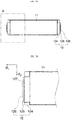
- the electrode tab 12 may include a terrace portion 124 formed by an exterior material being bonded along a side edge of the electrode assembly in which the electrode tab 12 protrudes, an insulating portion 125 that can increase a degree of sealing of the exterior material at a position at which the electrode tab 12 is drawn from the terrace portion 124 with securing an electrically insulated state, and an electrode tab portion 126 that is drawn from the insulating portion 125 and having at least a portion thereof inserted into the hole 23a being bound.
- the bent portion 121 may be formed on the insulating portion 125.
- the bent portion 121 may be formed by the electrode tab portion 126 being bent outside the insulating portion 125, but the present disclosure is not limited thereto, and the bent portion 121 may be formed on the insulating portion 125 by the insulating portion 125 of the electrode tab 12 being bent. As described above, as the bent portion 121 is formed on the insulating portion 125, an overall length L 1 of the electrode tab 12 may be reduced, reducing the overall volume of the battery module 1.
- bent portion 121 when the bent portion 121 is formed on the insulating portion 125, bending may be performed within a range in which the insulating material of the insulating portion 125 is not torn or damaged, and thus a volume occupied by the electrode tab 12 in the battery module 1 may be reduced while insulation performance of the insulation portion 125 is maintained, and an energy density of the battery module 1 may also be increased.
- FIG. 7A is a view illustrating a secondary battery according to an embodiment of the present disclosure
- FIG. 7B is an enlarged view of a portion A of FIG. 7A .
- chamfer portions 127 may be formed at both side ends of the electrode tab 12 so that the electrode tab 12 may be easily inserted into the hole 23a when the electrode tab 12 is inserted into the hole 23a.
- both side edges of the electrode tab 12 in a direction d 2 of the length L 5 of the end surface of the electrode tab 12 may be cut obliquely with respect to a direction d 1 of the length L 1 of the electrode tab 12, and the chamfer portions 127 may be formed on both of the side ends of the electrode tab 12. Since the chamfer portions 127 are formed at the ends of the electrode tab 12 as described above, insertion of the electrode tab 12 into the hole 23a may be induced in a process of inserting the electrode tab 12 into the hole 23a, and the insertion of the electrode tab 12 may be facilitated.
- FIG. 8 is a perspective view illustrating a support plate 30, a bus bar 20a, and a fixing plate 40 according to an embodiment of the present disclosure.
- FIG. 9 is a view illustrating a state in which the support plate 30, the bus bar 20a, and the fixing plate 40 of FIG. 8 are coupled.
- FIG. 10 is a cross-sectional view taken along line A-A' of FIG. 9 .
- FIG. 9 is a view illustrating a state in which a plurality of secondary batteries 10 are not connected to an assembly of the support plate 30, the bus bar 20a, and a fixing plate 40
- FIG. 10 is a view illustrating a state in which the electrode tab 12 is inserted into one side of the assembly of the support plate 30, the bus bar 20a, and the fixing plate 40.
- the battery module 1 may further include the support plate 30 in which a plurality of support holes 32 corresponding to the holes 23a of the bus bar 20a are formed.
- the support plate 30 may be located between the plurality of battery cells 11 and the bus bar 20a to fixedly support the bus bar 20a.
- the support plate 30 may include a plate-shaped support plate body 31 and a plurality of support holes 32 that are formed on the support plate body 31 to correspond to the plurality of holes 23a of the bus bar 20a.
- a size of a cross-section of the support hole 32 may be greater than a size of a cross-section of the hole 23a of the bus bar 20a, and the bent portion 121 of the electrode tab 12 may be brought into contact with one side of an outer circumferential surface of the support hole 32 and supported thereby.
- the bent portion 121 may be formed on the insulating portion 125 of the electrode tab 12 as described above.
- the gap L 3 between the electrode tab 12 and the hole 23a of the bus bar 20a may be constantly maintained and a position of the electrode tab 12 inserted into the hole 23a may be fixed, and thus a welding line may be easily traced when the electrode tab 12 is welded later.
- the bent portion 121 may be brought into close contact with one side of an outer circumferential surface of a support hole 32 to prevent the laser L from being directly applied to the battery cell 11.
- the support plate may be coated with an insulating material or the support plate may be formed of an insulating material and the plurality of electrode tabs may be respectively inserted into the plurality of support holes, an insulated state between the electrode tabs may be maintained.
- the battery module 1 may further include the fixing plate 40, which couples and fixedly supports the bus bar 20a and the support plate 30.
- the battery module 1 may further include the fixing plate 40 in which a plurality of bus bar exposure holes 42 are formed to correspond to the holes 23a of the bus bar 20a.
- the fixing plate 40 may be located at an outer side of the bus bar 20a, and may fixedly support the bus bar 20a by being coupled to at least a portion of the support plate 30 on at least a portion of the fixing plate 40. Further, the fixing plate 40 may be positioned to cover an outer surface of the bus bar 20a, and thus may protect the bus bar 20a from foreign matter or the like.
- the fixing plate 40 may include a plate-shaped fixing plate body 41 and the plurality of bus bar exposure holes 42 formed in the fixing plate body 41 to correspond to the plurality of holes 23a of the bus bar 20a.
- a size of a cross-section of the bus bar exposure hole 42 may be greater than the size of the cross-section of the hole 23a of the bus bar 20a.
- the bus bar exposure hole 42 may be formed to have a size such that the protruding portion 22a may be exposed to the outside, and thus a welding portion may be easily traced during welding.
- the fixing plate 40 may be formed in a form in which a portion other than the bus bar exposure holes 42 surrounds an outer surface of the plate 21a of the bus bar 20a, and may be coupled to the support plate 30 with the bus bar 20a interposed therebetween to stably and fixedly support the bus bar 20a.
- two or more secondary batteries 10 may be connected in parallel through the bus bars 20a to be grouped into one parallel assembly 100, and a plurality of parallel assemblies 100 may be connected in series to form a battery module 1.
- two or more bus bars 20a may be provided, and a terminal portion 25a which can be connected to another external battery module or a charging and discharging device may be formed on at least a portion of each of the two bus bars 20a located at both ends of one side surface of the battery module 1.
- each of the terminal portions 25a may refer to a positive (+) pole or a negative (-) pole of the battery module 1 to which a plurality of parallel assemblies 100 are connected, and one of the two terminal portions 25a may be connected to the positive (+) pole and the other terminal portion may be connected to the negative (-) pole, according to an arrangement of electrodes of the plurality of parallel assembly 100.
- terminal support holes 44 may be formed at positions corresponding to the terminal portions 25a in at least a portion of both ends of the fixing plate 40, and the terminal portion 25a may be inserted and fixed to the terminal support hole 44.
- terminal portions 25a may be formed on at least a portion of each of the two bus bars 20a located at both ends of one side surface of the battery module 1. Furthermore, as illustrated in FIG. 9 , a position of the bus bar 20a may be fixedly supported by the terminal portion 25a being inserted into the terminal support hole 44 formed on the fixing plate 40.
- the terminal portion 25a may be exposed to the outside of the fixing plate 40 even while the bus bar 20a is surrounded by the fixing plate 40, and the terminal portion 25a may be connected to an external battery module, a charging and discharging device, or the like.
- At least one fixing member 43 which is located between the plurality of bus bars 20a and fixedly supports a position of the bus bar 20a, may be formed on at least a portion of the fixing plate 40.
- at least one fixing member 43 may protrude from at least a portion of the fixing plate body 41 toward the bus bar 20a.
- the number of fixing members 43 formed may correspond to the number of the bus bars 20a.
- one fixing member may be formed at one side of the fixing plate 40, and the fixing member 43 may be positioned between the two bus bars 20a to fixedly support the positions of the bus bars 20a.
- a fixing member insertion groove 33 corresponding to the fixing member 43 may be recessed in at least a portion of the support plate 30 at the bus bar 20a.
- the fixing member 43 protruding from the fixing plate 40 may be inserted into one side of the support plate 30, and the fixing member 43 may be positioned in the fixing member insertion groove 33 so that the fixing member 43 may firmly and fixedly support the bus bar 20a.
- the fixing plate 40 may include a plurality of fastening protrusions 411, which are formed by at least a portion of the fixing plate body 41 protruding toward the bus bar 20a, and the fastening protrusions 411 may be coupled to at least a portion of the support plate 30 so that the support plate 30 and the fixing plate 40 may be coupled to each other.
- a locking portion (not illustrated) may be formed at the fastening protrusion 411
- a locking groove (not illustrated) corresponding to the locking portion may be formed on at least a portion of the support plate 30, and thus the fixing plate 40 and the support plate 30 may be engaged and coupled to the bus bar 20a interposed therebetween through the fastening of the locking portion and the locking groove.
- this configuration is merely an example, and the present disclosure is not limited thereto. That is, it is sufficient for the fastening protrusions 411 to be brought into contact with at least a portion of the support plate 30 to be fastened and coupled.
- the fixing plate 40 may be formed to surround all of the remaining portions other than the protruding portion 22a of the bus bar 20a, and thus the possibility of electrical connection with other components around the bus bar 20a may be preemptively blocked when the battery module 1 is used.
- the bus bar 20a may further include at least one through-hole 26a, which is formed at a position corresponding to a position of the insertion protrusion 45 at the plate 21a and through which the insertion protrusion 45 passes.
- the support plate 30 may be formed on the support plate body 31 so that the insertion protrusion 45 may be inserted therein, and the support plate 30 may further include at least one fastening hole 34, which may be coupled to the insertion protrusion 45 when the insertion protrusion 45 is inserted thereinto.
- the insertion protrusion 45, the through-hole 26a, and the fastening hole 34 may be formed at positions corresponding to positions of the fixing plate body 41, the plate 21a, and the support plate body 31, respectively.
- the insertion protrusion 45 may be formed at a position adjacent to the bus bar exposure hole 42.
- the through-hole 26a may be formed at a position adjacent to the hole 23a
- the fastening hole 34 may be formed at a position adjacent to the support hole 32.
- the insertion protrusion 45 may be inserted into the fastening hole 34 of the support plate 30 through the through-hole 26a of the bus bar 20a.
- the insertion protrusion 45 which may be inserted into the fastening hole 34, and the fastening hole 34 may be coupled so that the support plate 30 and the fixing plate 40 may be coupled, and the position of the bus bar 20a may be fixed.
- the insertion protrusion 45 may be thermally fused while the insertion protrusion 45 is inserted into the fastening hole 34 through the through-hole 26a so that the insertion protrusion 45 may be attached to one surface of the support plate body 31, and accordingly, the fixing plate 40, the bus bar 20a, and the support plate 30 may be coupled so that the position of the bus bar 20a may be stably and fixedly supported.
- the support plate 30 and the fixing plate 40 may be formed to have a size corresponding to a cross-sectional area of a stacked structure of the plurality of battery cells 11 in a stacking direction. Accordingly, an unnecessary volume of the battery module 1 may be minimized despite the volume of the support plate 30 and the fixing plate 40, and thus the bus bar 20a and the electrode tabs 12 may be fixedly supported while energy density of the battery module 1 is not hindered.
- FIGS. 11A and 11B are front and rear views, respectively, of a battery module 1 according to an embodiment of the present disclosure.
- a secondary battery at a left end of FIG. 11A is a secondary battery at a right end of FIG. 11B .
- the battery module 1 illustrated in FIGS. 11A and 11B is in an electrically connected state.
- two or more secondary batteries 10 may be connected in parallel through the bus bar 20a to be grouped into one parallel assembly 100, and a plurality of parallel assemblies 100 may be connected in series to form a battery module 1.
- three positive (+) poles of the secondary batteries 10 may be connected in parallel through the bus bar 20a to form the one parallel assembly 100a, and the parallel assembly 100a may be arranged to be adjacent to a parallel assembly 100b in which negative (-) poles are connected in parallel and connected to the parallel assembly 100b in series.
- four parallel assemblies 100a and 100b having different electrodes may be provided on the basis of one direction of the plurality of secondary batteries 10 and may be connected in series through bus bars 20a. That is, a total of twelve secondary batteries 10 may be connected.
- this configuration is merely an example, and the present disclosure is not limited thereto. That is, two secondary batteries 10 having the same electrode may be connected in parallel to form one parallel assembly 100 and a plurality of parallel assemblies 100 having different electrodes at one side thereof may be connected in series to form one battery module 1.
- the number of the secondary batteries 10 constituting one parallel assembly 100 may be freely selected and the number of the parallel assemblies 100 to be connected in series may also be freely selected, a degree of freedom in configuring the battery module 1 may be improved, which may be achieved by the number of the holes 23a formed in the bus bar 20a being simply changed.
- the bus bar 20a may further include a voltage sensing connection portion 200a formed on at least a portion of the plate 21a.
- the voltage sensing connection portion 200a may be connected to a voltage sensing module (not illustrated) for measuring a voltage of the parallel assembly 100 and the like.
- the voltage sensing module may be a configuration, such as a voltage sensing circuit, a battery management module, or the like located outside the battery module 1 and capable of measuring and confirming a state of a voltage of the parallel assembly 100.
- a laser may be applied to an end surface of the electrode tab 12 at predetermined intervals to the end surface of the electrode tab 12 so that a plurality of electrode tab welding portions 123 may be formed at the predetermined intervals. See FIG. 16A .
- the present disclosure is not limited thereto, and, as illustrated in FIG. 16B that will be described below, the laser may be continuously applied to the end surface of the electrode tab 12 so that the electrode tab welding portion 123 may be formed to have a continuous shape in a straight line.
- FIGS. 11A and 11B are views for describing an electrical connection relationship between the plurality of secondary batteries 10 except that the terminal portion 25a is omitted, and the terminal portion 25a may protrude from at least a portion of the bus bars 20a at both ends of the plurality of bus bar 20a.
- FIGS. 12A and 12B are cross-sectional views illustrating a bus bar 20b according to an embodiment of the present disclosure.
- FIG. 12A is a cross-sectional view illustrating the bus bar 20b
- FIG. 12B is a cross-sectional view illustrating a state in which an electrode tab 12 is inserted into a hole 23b of the bus bar 20b.
- a protruding portion 22b of a bus bar 20b may include a tapered cross-section shape.
- the protruding portion 22b may be formed to have a conical cross-section with the hole 23b positioned at the top of the conical cross-section.
- the sides of the protruding portion 22b may be formed to be inclined surfaces.
- the protruding portion 22b may be formed to have a shape such that a cross-section of an inner space of the protruding portion 22b is reduced near the hole 23b.
- the protruding portion 22b may function to induce the electrode tab 12 to be inserted into the hole 23b due to an inclination thereof when the electrode tab 12 is inserted into the hole 23b.
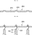
- FIGS. 13A and 13B are cross-sectional views illustrating a bus bar 20c according to an embodiment of the present disclosure.
- a bus bar 20c may include a plate 21c and a plurality of holes 23c.
- the bus bar 20c may include a plurality of holes 23c, which are formed in the plate 21c at predetermined intervals.
- a size, such as an area or the like, of the plate 21c and the positioning of the holes 23c may correspond to the number and width of the battery cells 11 and the positioning of the electrode tabs 12. Since a detailed description thereof is identical to that of the bus bar 20a according to an embodiment of the present disclosure above, overlapping descriptions will be omitted.
- the plate 21c may include protruding portions 22c, which are also referred to as tab connection portions 22c.
- Each of the tab connection portions 22c may protrude from an outer periphery of each of the holes 23c in a direction in which the electrode tab 12 protrudes, and the electrode tab 12 melted by the laser L may then be brought into contact with the tab connection portion 22c and electrically connected to the bus bar 20c when the battery cells 11 are electrically connected by laser welding.
- the sides of each tab connection portion 22c are substantially perpendicular to the plate 21c.
- the sides of each protruding portion is an inclined surface
- the tab connection portion 22c is formed on the plate 21c, reflected light of the laser L may be minimized when the laser L is applied for electrical connection between the battery cells 11. Accordingly, dispersion of energy of the laser L may be prevented and the laser L having a specific amount of energy may be uniformly applied during welding. Thus a process error in the welding process may be reduced and a production speed of a battery module 1 may be improved.
- FIG. 14A is a cross-sectional view illustrating the bus bar 20c according to an embodiment of the present disclosure
- FIG. 14B is a cross-sectional view illustrating a state in which the electrode tab 12 is inserted into the hole 23c of the bus bar 20c.
- the battery cell 11 may be arranged to be perpendicular to the ground, and the bus bar 20c may be mounted on the electrode tab 12 at an outer side of the battery cell 11. It should be apparent to those skilled in the art that the present disclosure is described with reference to drawings in which the battery cells 11 may be arranged in parallel to the ground, and thus a position of the bus bar 20c may be changed.
- the hole 23c may be formed to have a depth L 6 relatively smaller to a length L 1 of the electrode tab 12, so that the electrode tab 12, when it is inserted into one side of the bus bar 20c, may protrude from the other side of the bus bar 20c.
- the electrode tab 12 may preferably protrude by about 1 mm or more from an outer end of the tab connection portion 22c so that the laser L is applied to the electrode tab 12 obliquely with respect to a central axis of a direction d 1 of the length L 1 of the electrode tab 12.
- the bus bar 20c may be welded by applying only the electrode tab 12 without applying the bus bar 20c in a welding process that will be described below.
- the electrode tab 12 when the electrode tab 12 protrudes too much, the laser L should be repeatedly applied to the electrode tab 12. Also, if the electrode tab 12 is not sufficiently melted during the welding, the electrode tab 12 and the bus bar 20c may not be smoothly connected. Therefore, the electrode tab 12 preferably protrudes by about 3 mm or less.
- a bent portion 121 may be formed on the electrode tab 12.
- the bent portion 121 may be formed by a predetermined portion of the electrode tab 12 being bent.
- the bent portion 121 is not limited to being formed by the predetermined portion of the electrode tab 12 being bent, and a protruded portion may be formed at the predetermined portion of the electrode tab 12.
- bent portion 121 since a detailed description of the bent portion 121 is identical to that of the above-described electrode tab 12 according to an embodiment of the present disclosure, the overlapping descriptions will be omitted.
- connection structure of the bent portion 121 of the electrode tab 12 and the support plate 30, the fixing plate 40, and the parallel assembly 100 described in the specification is identical to that of each of the battery modules 1 according to various embodiments of the present disclosure above, overlapping descriptions thereof will be omitted.
- a battery module 1 may be manufactured by stacking a plurality of battery cells 11, arranging an electrode tab 12 included in each of the plurality of battery cells 11 at one side of the plate 21c of the bus bar 20c adjacent a respective hole 23c among a plurality of holes 23c of the plate 21c, inserting the electrode tabs 12 in their corresponding holes 23c, and electrically connecting the plurality of battery cells 11.
- the plurality of battery cells 11 may be electrically connected by laser welding the electrodes 12 to the plate after the electrodes are positioned within their respective holes 23c.
- a laser L may be applied only to the electrode tabs 12 as described above.
- the electrode tabs 12 and the busbar 20a maybe coupled after the electrode tabs 12 melt sufficiently. Dislike a conventional method of melting and welding two base materials, problem of specific portions being connected while a portion is not welded as one of the two base materials is not melt sufficiently may be minimized. Thus a welding state may be visually checked, and quality and production speed of the battery module 1 may be significantly improved.
- the welding may be performed on an end surface of the electrode tab 12 at regular intervals, the laser L may be repeatedly applied to the end surface in a shape of a circle, and centers of the circles may be located along an axis 122 of a direction d 2 of a length L 5 of the end surface of the electrode tab 12.
- the welded portion of the electrode tab 12 may be uniformly melted by wobble-type welding performed by the circles being repeatedly formed to overlap.
- stability of a process of manufacturing the battery module 1 may be improved in the welding process of the electrode tab 12 included in the battery cell 11 which is vulnerable to high temperature.
- a support plate 30 may be arranged between the plurality of battery cells 11 and the bus bar 20c, and the electrode tab 12 may be positioned to pass through support holes 32 of the support plate 30.
- the electrode tab 12 may be inserted at one side of the plate 21c while passing through the support holes 32 of the support plate 30, and thus may be arranged on at least a portion of the plurality of holes 23c.
- the electrode tab 12 may include the bent portion 121 formed by being bent and folded, and the bent portion 121 may be brought into close contact with one side of an outer circumferential surface of the support hole 32 so that the electrode tab 12 may be fixedly supported.
- a fixing plate 40 may be arranged at the other side of the bus bar 20a, and the position of the bus bar 20a may be fixedly supported by coupling the fixing plate 40 and the support plate 30.
- a plurality of insertion protrusions 45 which are formed by forming at least a portion of the fixing plate body 41 to protrude, may be formed on side surfaces of the support plate 30 of the fixing plate 40, and a plurality of fastening holes 34 corresponding to the insertion protrusions 45 may be formed on at least a portion of a support plate body 31.
- the insertion protrusions 45 may be inserted in the fastening holes 34 and fused so that the fixing plate 40 and the support plate 30 may be coupled with the bus bar 20a interposed therebetween, and a position of the bus bar 20a may be fixedly supported.
- a hole 23a and a protruding portion 22a that will be described below may be exposed to the outside through a bus bar exposure hole 42 of the fixing plate 40, and thus an operator may easily trace a welding line when the electrode tab 12 and the bus bar 20a are welded.
- the protruding portion 22a may be formed at a position at which the hole 23a is formed. Specifically, the protruding portion 22a may be formed to create an entry space having a width L 4 into which the electrode tab 12 enters at one side of the protruding portion 22a is reduced near the holes 23a, and the insertion of the electrode tab 12 may be facilitated when the above-described electrode tab 12 is inserted into the hole 23a of the plate 201a.
- the protruding portion 22b may be formed on the plate 21b of the bus bar 20b at a position at which the hole 23b is formed.
- the protruding portion 22b may be formed to have a cross-section shape tapered toward the hole 23b, and all of the holes 23b may be formed to have a tapered cross-section shape so that the insertion of the electrode tab 12 into the hole 23b may be facilitated during the insertion of the electrode tab 12 into the hole 23b.
- FIG. 15 is a cross-sectional view illustrating a position at which laser welding is performed on a protruding electrode tab 12 according to an embodiment of the present disclosure.
- the battery module 1 may be manufactured by stacking a plurality of battery cells 11, inserting the electrode tab 12 included in each of the plurality of battery cells 11 into one side of the plate 21c in which the plurality of holes 23c are formed and arranging the electrode tab 12 to protrude toward the other side of the plate 21c in at least a portion of the plurality of holes 23c, and electrically connecting the plurality of battery cells 11.
- the battery module 1 may further include a bus bar assistance member 24 formed of an insulating material such as plastic or the like.
- the bus bar assistance member 24 may be formed to surround all of the remaining portions other than the tab connection portion 22c, and thus the possibility of electrical connection with other components around the bus bar 20c may be preemptively blocked when the battery module 1 is used.
- the electrode tab 12 may be inserted into one side of the plate 21c in which the plurality of holes 23c are formed to protrude from the other side of the plate 21c.
- the electrode tab 12 may be arranged to protrude by a length of 1 to 3 mm from an outer end of the hole 23c, as described above.
- the plurality of battery cells 11 may be electrically connected by laser welding, and the laser L may be applied only to the electrode tab 12, as described above.
- the bus bar 20c is welded by only the electrode tab 12 being applied without applying the bus bar 20c, problem of specific portions being connected while a portion is not welded may be minimized in comparison to a conventional method of melting and welding two base materials.
- a welding state may be visually checked, and quality and production speed of the battery module 1 may be significantly improved.
- FIGS. 16A and 16B are views illustrating a state in which laser welding is performed on an electrode tab 12 according to an embodiment of the present disclosure.
- welding may be performed on an end surface of the electrode tab 12 at regular intervals.
- An enlarged view in FIGS. 16A and 16B illustrates that welding is not performed in a straight line like a conventional laser welding, and the laser L is repeatedly applied to the end surface of the electrode tab 12 in a shape of a circle, and centers of the circles are located along an axis 122 in a direction d 2 of the length L 5 of the end surface.
- the welded portion of the electrode tab 12 may be uniformly melted through wobble-type welding performed by the circles being repeatedly formed to overlap.
- welding may be effectively applied, and stability of a process of manufacturing the battery module 1 may be improved in a welding process of the electrode tab 12 included in the battery cell 11 which is vulnerable to high temperature.
- the welding is not limited to being performed at regular intervals.
- the laser may be continuously applied to the end surface of the electrode tab 12 so that the electrode tab welding portion 123 may be formed to have a continuous shape in a straight line.
- FIGS. 17A and 17B are views illustrating a state in which a laser is applied to the electrode tab 12 at an angle with respect to a direction d 1 of the length L 1 of the electrode tab 12 according to an embodiment of the present disclosure.
- the laser L may be applied obliquely with respect to a central axis of a direction d 1 of the length L 1 of the electrode tab 12 inserted into the hole and protruding therefrom. Accordingly, when the laser L is applied obliquely to the end surface of the electrode tab 12, it is possible to reduce errors and accidents by minimizing the possibility of the laser L being directly applied to the battery cell 11. As the laser L is obliquely applied, the welding process on the end surface of the electrode tab 12 may be visually confirmed, and thus quality and production speed of the battery module 1 may be improved. However, if necessary, the laser L may be applied perpendicularly to the end surface of the electrode tab 12.
- the laser L may be applied to the end surface of the electrode tab 12, as illustrated in FIG. 17A , but the present disclosure is not limited thereto, and the laser L may be applied to one side surface of the electrode tab 12 according to a material of the electrode tab 12, as illustrated in FIG. 17B . Furthermore, it should be apparent to those skilled in the art that the laser L may be applied around the bus bar 20c.
- a battery module which allows the number of assembling processes to be reduced for electrically connecting a plurality of battery cells.
- a battery module capable of preventing deformation of shapes of electrode tabs due to a shape of a bus bar being deformed can be provided.
- a battery module of the present disclosure allows costs to be reduced since the number of processes may be reduced.
- electrode tabs can be uniformly melted.
Landscapes
- Chemical & Material Sciences (AREA)
- Chemical Kinetics & Catalysis (AREA)
- Electrochemistry (AREA)
- General Chemical & Material Sciences (AREA)
- Engineering & Computer Science (AREA)
- Manufacturing & Machinery (AREA)
- Connection Of Batteries Or Terminals (AREA)
- Physics & Mathematics (AREA)
- Optics & Photonics (AREA)
- Plasma & Fusion (AREA)
- Mechanical Engineering (AREA)
Abstract
Description
- This application claims priority to and the benefit of Korean Patent Application No.
10-2016-0177900, filed on December 23, 2016 10-2017-0041875, filed on March 31, 2017 10-2017-0177048, filed on December 21, 2017 - Exemplary embodiments of the present disclosure relate to a battery module.
- More powerful secondary batteries that can be charged and discharged many times are actively being researched due to their use in advanced fields such as digital cameras, cellular phones, laptop computers, hybrid vehicles, and the like. Examples of secondary batteries include a nickel-cadmium battery, a nickel-metal hydride battery, a nickel-hydrogen battery, and a lithium secondary battery. The lithium secondary battery typically has an operating voltage of 3.6 V or higher and can be used as a power source for portable electronic devices. Also, a plurality of lithium secondary batteries connected in series can be used to power a high-output hybrid vehicle. Use of the lithium secondary battery has rapidly increased because its operating voltage thereof is approximately three times higher than that of the nickel-cadmium battery or the nickel-metal hydride battery. Also, the lithium secondary battery has excellent energy density per unit of weight.
- Typically, a bus bar is brought into contact with the electrode tabs of battery cells for connecting a plurality of battery cells. A conventional bus bar is formed to have a C shape. Electrode tabs may be brought into contact with a C-shaped bus bar so that two or more battery cells can be electrically connected. Connecting the battery cells may require at least one of cutting and bending the electrode tabs of the battery cells. As the number of battery cells, e.g. three battery cells, four battery cells, or the like (that is, parallel connection of three cells or parallel connection of four cells) to be connected varies, the cutting and bending dimensions of electrode tabs also vary. Because existing battery modules require deforming the electrode tabs for coupling the battery cells, the number of required process operations is increased, which in turn renders the manufacturing process more complicated and increases its cost.
- Korean Patent Application Publication No.
10-2015-0110078 (Published on October 2, 2015 - Embodiments of the present disclosure provide a battery module allowing the number of assembling processes to be reduced due to electrode tab processing for electrically connecting a plurality of battery cells being simplified.
- Other embodiments of the present disclosure provide a battery module capable of preventing deformation of shapes of electrode tabs by a shape of a bus bar being deformed.
- Other embodiments of the present disclosure provide a battery module allowing costs to be reduced according to a reduction in the number of processes.
- Other embodiments of the present disclosure provide a battery module capable of uniformly melting electrode tabs when a plurality of battery cells are electrically connected to each other.
- Other embodiments of the present disclosure provide a battery module allowing a connection state to be visually confirmed when a plurality of battery cells are electrically connected by welding or the like.
- According to an aspect of the present disclosure, there is provided a battery module including a plurality of battery cells each including at least one electrode tab, and a bus bar in contact with the electrode tabs to electrically connect the plurality of battery cells, wherein the bus bar includes a plate in which a plurality of holes are formed, and the electrode tabs are inserted into at least a portion of the plurality of holes to electrically connect the plurality of battery cells.
- Each of the plurality of electrode tabs may be inserted into the corresponding one of the plurality of holes and fixed.
- The electrode tab may be inserted into one side of the plate and protrude to the other side of the plate.
- The electrode tab may protrude by a length of 1 to 3 mm from an outer end of the hole.
- The plate may include a protruding portion formed at a periphery of a position at which the hole is formed.
- A cross-section of the periphery of the hole may be formed to be tapered toward one side of the plate so that the electrode tab may be inserted into the hole.
- A width of an entry space into which the electrode tab enters at the one side of the plate may be reduced near the hole.
- The plate may include a tab connection portion configured to protrude from an outer periphery of the hole to an outside of the plate.
- The electrode tab and the plate may be connected to have a wobble welding shape by laser welding.
- The hole may be formed to correspond to a thickness and a length of the electrode tab.
- A sum of both gaps between the hole and the electrode tab inserted into the hole may range from 0.1 mm to 0.2 mm.
- The electrode tab may be formed in a straight line without being bent.
- At least one electrode tab includes a bent portion and a straight portion, and at least a part of the straight portion is inserted into its respective hole.
- The at least one electrode tab may include an insulating portion formed on at least a portion of the electrode tab, and the bent portion may be formed on the insulating portion.
- The battery module may further include a support plate in which a plurality of support holes corresponding to the holes are formed and the support plate may be located between the plurality of battery cells and the bus bar.
- The bent portion may be formed at the electrode tab and the bent portion may be supported to be in contact with one side of the support hole.
- The battery module may further include a fixing plate in which a plurality of bus bar exposure holes corresponding to the holes are formed and the bus bar may be located between the support plate and the fixing plate and may be fixedly supported thereby.
- A plurality of bus bars may be provided, at least two of the plurality of electrode tabs may be connected to at least one of the plurality of bus bars in parallel to form a parallel assembly, and a plurality of the parallel assemblies may be provided and connected in series or in parallel.
- According to another aspect of the present disclosure, there is provided a method of manufacturing a battery module including providing a plurality of battery cells stacked in parallel next to each other, each battery cell including an electrode tab, providing a bus bar comprising a plurality of holes formed at a regular interval and configured to receive the plurality of electrode tabs, positioning the bus bar adjacent to the battery cells so that the plurality of holes of the bus bar are positioned adjacent to the plurality of corresponding electrode tabs ,inserting the plurality of electrode tabs into the corresponding holes of the bus bar, and fixing the electrode tabs to the bus bar.
- The electrode tab may protrude toward the other side of the plate.
- The electrode tab may protrude by a length of 1 to 3 mm from an outer end of the hole.
wherein said fixing includes welding the electrode tabs to the bus bar.
wherein said welding includes laser welding of only the electrode tabs and not of the bus bar. - The laser may be repeatedly applied to an end surface of the electrode tab in a shape of a circle, and centers of the circles may be located along an axis of a longitudinal direction of the end surface.
- The laser may be applied to the electrode tab obliquely with respect to a central axis of a longitudinal direction thereof.
- A support plate may be arranged between the plurality of battery cells and a bus bar, and the electrode tab may be positioned to pass through a support hole of the support plate.
- The bus bar may be coupled to at least a portion of the support plate and may be fixedly supported thereby.
- A fixing plate may be arranged at another side of the bus bar, and the hole may be exposed to the outside through a bus bar exposure hole of the fixing plate.
- The above and other objects, features and advantages of the present disclosure will become more apparent to those of ordinary skill in the art by describing exemplary embodiments thereof in detail with reference to the accompanying drawings, in which:
-
FIG. 1 is a view illustrating a secondary battery according to an embodiment of the present disclosure; -
FIG. 2 is a view illustrating a state in which a bus bar is brought into contact with the secondary battery according to an embodiment of the present disclosure; -
FIGS. 3A and 3B are views illustrating the bus bar according to an embodiment of the present disclosure; -
FIG. 4A is a cross-sectional view illustrating the bus bar according to an embodiment of the present disclosure; -
FIG. 4B is a cross-sectional view illustrating a state in which an electrode tab is inserted into a hole of the bus bar according to an embodiment of the present disclosure; -
FIG. 5A is a cross-sectional view illustrating the bus bar according to an embodiment of the present disclosure; -
FIG. 5B is a cross-sectional view illustrating a state in which an electrode tab is inserted into a hole of a bus bar according to an embodiment of the present disclosure; -
FIG. 6 is a view illustrating a state in which a bent portion is formed on an insulating portion of the electrode tab; -
FIG. 7A is a view illustrating a secondary battery according to an embodiment of the present disclosure; -
FIG. 7B is an enlarged view of a portion A ofFIG. 7A ; -
FIG. 8 is a perspective view illustrating a support plate, a bus bar, and a fixing plate according to an embodiment of the present disclosure; -
FIG. 9 is a view illustrating a state in which the support plate, the bus bar, and the fixing plate ofFIG. 8 are coupled; -
FIG. 10 is a cross-sectional view taken along line A-A' ofFIG. 9 ; -
FIG. 11A is a front view illustrating an electrical connection state of a battery module according to an embodiment of the present disclosure; -
FIG. 11B is a rear view illustrating an electrical connection state of the battery module according to an embodiment of the present disclosure; -
FIG. 12A is a cross-sectional view illustrating a bus bar according to an embodiment of the present disclosure; -
FIG. 12B is cross-sectional view illustrating a state in which an electrode tab is inserted into a hole of the bus bar according to an embodiment of the present disclosure; -
FIGS. 13A and 13B are views illustrating the bus bar according to an embodiment of the present disclosure; -
FIG. 14A is a cross-sectional view illustrating the bus bar according to an embodiment of the present disclosure; -
FIG. 14B is a cross-sectional view illustrating a state in which the electrode tab is inserted into the hole of the bus bar according to an embodiment of the present disclosure; -
FIG. 15 is a cross-sectional view illustrating a position at which laser welding is performed on a protruding electrode tab according to an embodiment of the present disclosure; -
FIGS. 16A and 16B are views illustrating a state in which laser welding is performed on the electrode tab according to an embodiment of the present disclosure; and -
FIGS. 17A and 17B are views illustrating a state in which a laser is applied to the electrode tab at an angle with respect to a longitudinal direction of the electrode tab according to an embodiment of the present disclosure. - Hereinafter, exemplary embodiments of the present invention will be described in detail with reference to the drawings. However, we note that these embodiments are only examples of the present invention and are not intended to limit the present disclosure.
- The drawings are not necessarily to scale and, in some instances, proportions may have been exaggerated in order to clearly illustrate features of the embodiments.
- It will be further understood that when an element is referred to as being "connected to", or "coupled to" another element, it may be directly on, connected to, or coupled to the other element, or one or more intervening elements may be present. In addition, it will also be understood that when an element is referred to as being "between" two elements, it may be the only element between the two elements, or one or more intervening elements may also be present.
- Detailed descriptions of well-known structures and functions which may unnecessarily obscure the present disclosure are omitted. Some terms described below are defined in consideration of functions in the present disclosure, and meanings thereof may vary depending on, for example, a user or operator's intentions or customs. Therefore, the meanings of terms should be interpreted on the basis of the scope of the present disclosure throughout this specification.
- Hence, it should be understood that the spirit and scope of the present invention are defined by the appended claims and that he following embodiments serve the purpose of describing the technological scope of the present invention to those skilled with ordinary skill in the art to which the present invention belongs.
- Hereinafter, the various embodiments of the present invention will be described in detail with reference to the attached drawings.
FIG. 1 is a view illustrating asecondary battery 10 according to an embodiment of the present disclosure.FIG. 2 is a view illustrating a state in which abus bar 20a is arranged on the secondary battery.FIGS. 3A and 3B are views illustrating thebus bar 20a. In describing thesecondary battery 10 and thebus bar 20a, references will be made toFIGS. 1 ,2 ,3A, and 3B . - Referring to
FIG. 1 , thesecondary battery 10 may include a plurality ofbattery cells 11 andelectrode tabs 12 drawn from thebattery cells 11. - Referring to
FIG. 2 , thebus bar 20a according to the embodiment of the present disclosure may have a shape in which holes 23a (shown inFIG. 3B ) are formed in aplate 21a (shown inFIGS. 3 ). A plurality ofholes 23a may be formed in theplate 21a, and anelectrode tab 12 is welded to each of theholes 23a so that a plurality of weldedbattery cells 11 may be electrically connected. Since theelectrode tabs 12 are inserted into therespective holes 23a, it is not necessary to deform the shape of theelectrode tabs 12. The number of the plurality ofholes 23a which are formed in theplate 21a of thebus bar 20a correspond to the number of thebattery cells 11 to be connected thereto via thebus bar 20a. Therefore, thebattery cells 11 may be electrically connected without changing the shape of theelectrode tabs 12 regardless of the number ofbattery cells 11 to be connected in order to electrically connect thebattery cells 11. Details of theplate 21a and theholes 23a will be described below. - Referring to
FIGS. 3A and 3B , thebus bar 20a may include theplate 21a, protrudingportions 22a, and theholes 23a. The plurality ofholes 23a are formed in theplate 21a at predetermined intervals, and each may have a suitable shape and sufficient size so that theelectrode tabs 12 can be inserted into theholes 23a for electrically connecting the plurality ofbattery cells 11. Eachelectrode tab 12 may be welded to theplate 21a after it is inserted into acorresponding hole 23a. Therefore, the plurality of weldedbattery cells 11 may be electrically connected. In the illustrated embodiment, eachhole 23a may be formed to have a slit shape. - An area or size of the
plate 21a may be determined according to the number of thebattery cells 11 welded to theplate 21a. For example, when twobattery cells 11 are electrically connected, theplate 21a may be formed to have an area or size to accommodate the twoholes 23a in which the twoelectrode tabs 12, one from each of the twostacked battery cells 11, may be welded. Similarly, when threebattery cells 11 are electrically connected, theplate 21a may be formed to have an area or size to accommodate the threeholes 23a in which the threeelectrode tabs 12, one from each of the three stacked battery cells, 11 may be welded. Hence, the area or size of theplate 21a is determined according to the number of thebattery cells 11 to be connected. Using thebus bar 20a according to an embodiment of the present disclosure, thebattery cells 11 are electrically connected without having to change the shape of the electrode tabs. By changing the area or size of theplate 21a and the number of theholes 23a according to the number of the battery cells and their individual size, thebus bar 20a of the present invention can electrically couple the battery cells together without the need to change the shape of theelectrode tabs 12 and/or cut theelectrode tabs 12. Hence, unlike existing techniques, which are used for electrically coupling a plurality of battery cells to form a battery module, there is no need to employ an additional process of abutting theelectrode tabs 12 to the bus bar which requires bending theelectrode tabs 12, deforming the shape of theelectrode tabs 12, and sometimes even cutting the electrode tabs. When thebus bar 20a of the present disclosure is used, only the steps of inserting theelectrode tab 12 in thebus bar 20a and then connecting theelectrode tab 12 and thebus bar 20a via welding are employed. Thus,bus bar 20a in accordance with the embodiment of the present disclosure simplifies the method of installing the bus bar for electrically coupling a plurality of battery cells to form a battery module. Specifically, as explained above, the present invention bus bar makes the abutting step by bending, deforming, and cutting of theelectrode tab 12 unnecessary. - The protruding
portions 22a may be formed at thebus bar 20a and have a convex shape according to the embodiment ofFIGS. 3A and 3B . Each of the protrudingportions 22a may be formed at a position at which acorresponding hole 23a is formed in theplate 21a. The protrudingportions 22a are shaped to induce theelectrode tab 12 to be inserted into thehole 23a. An enlarged view shown inFIG. 3B illustrates that thehole 23a is formed in the protrudingportion 22a. Since thehole 23a is formed to correspond to a thickness T1 and a length L1 of theelectrode tab 12, thehole 23a may be formed in theplate 21a to have a area corresponding to the thickness T1 of theelectrode tab 12.. Therefore, each protrudingportion 22a serves to more easily insert acorresponding electrode tab 12 into thehole 23a formed within the protrudingportion 22a. Details thereof will be described with reference toFIGS. 5A and 5B . - The plurality of
holes 23a may be formed in theplate 21a at predetermined intervals. The predetermined interval may be determined according to an interval between thebattery cells 11 which in turn depends upon the width of thebattery cells 11. Specifically, the predetermined interval may be determined according to a position at which theelectrode tab 12 is inserted into thehole 23a. The number of theholes 23a may be determined according to the number of thebattery cells 11 to be electrically connected. - Further, the
hole 23a may be formed to have a width L2 corresponding to those of theelectrode tab 12. SeeFIG. 4A . The depth of the hole L6 (shown in FIG. (A)) may correspond to the width of theplate 20a. Thehole 23a may be formed to have a depth L6 at which a state of the insertedelectrode tab 12 may be maintained before welding. Theelectrode tab 12 is inserted into thehole 23a and is in contact with theplate 21a so that thebus bar 20a can be maintained in place even before the welding takes place. Securing theelectrode tabs 12 within therespective holes 23a of theplate 21a may also be advantageous for facilitating the next step of welding theelectrode tabs 12 with theplate 21a of thebus bar 20a. - The
electrode tab 12 may be welded to theplate 21a in a state in which theelectrode tab 12 is inserted into thehole 23a and is in contact with theplate 21a. Therefore, the plurality ofbattery cells 11 welded to thebus bar 20a may be electrically connected. -
FIGS. 4A and 4B are views illustrating thebus bar 20a according to an embodiment of the present disclosure.FIG. 4A is a cross-sectional view illustrating thebus bar 20a, andFIG. 4B is a cross-sectional view illustrating a state in which theelectrode tabs 12 are inserted into theholes 23a of thebus bar 20a. - Referring to
FIGS. 4A and 4B , theholes 23a may be formed at theplate 21a at predetermined intervals of theplate 21a. Theelectrode tabs 12 may be inserted into theholes 23a. Thehole 23a may be formed to correspond to the thickness T1 and the length L1 of theelectrode tab 12 so that theelectrode tab 12 inserted into thehole 23a may be in contact with theplate 21a. In the exemplary embodiment ofFIGS. 4A and 4B , threeholes 23a may be formed in theplate 21a constituting onebus bar 20a. Thus, in this exemplary case, threebattery cells 11 welded through theholes 23a may be electrically connected. However, the present disclosure is not limited thereto, and any suitable number ofholes 23a may be formed according to the number ofbatter cells 11 to be connected. - Each
hole 23a may be formed within a corresponding protrudingportion 22a as illustrated inFIGS. 4A and 4B . Having the protrudingportions 22a is advantageous for more easily guiding and inserting thetabs 12 into their correspondingholes 23a. However, in embodiment of the present disclosure, the plate may not have any protruding portions, e.g., the plate may be substantially flat and may only haveholes 23a configured to receive thecorresponding tabs 12. Referring again to the embodiment ofFIGS 4A and 4B , eachhole 23a may have a wider entry part starting with a wider width L4 at one side of theplate 21a and a narrower width L2 at some depth inside theplate 21a. Because of this shape of the entry part of thehole 23a, theelectrode tab 12 can be more easily inserted into the narrower part of thehole 23a, which has a width L2. The entry part of eachhole 23a may also facilitate the precise positioning of thebus bar 20a so that thecorresponding tabs 12 may be readily inserted into theholes 23a prior to the welding step. -
FIGS. 5A and 5B are views illustrating thebus bar 20a according to an embodiment of the present disclosure.FIG. 5A is a cross-sectional view of thebus bar 20a andFIG. 5B is a cross-sectional view illustrating a state in which the electrode tabs are inserted into theholes 23a of thebus bar 20a. - Referring to
FIGS. 5A and 5B , eachelectrode tab 12 may include abent portion 121. In this illustrated embodiment ofFIGS 5A and 5B , thebent portion 121 may have a U shape. Thebent portion 121 may be formed by a predetermined portion of theelectrode tab 12 being bent. However, the present disclosure is not limited thereto. That is, in a variation of the illustrated embodiment, a protruding portion may be formed on the predetermined portion of theelectrode tab 12 and otherbent portions 121 may be formed. When external vibration or impact occurs in a state in which theelectrode tabs 12 are coupled to thebus bar 20a by welding, thebent portions 121 may absorb the impact at least partially, and thus reduce or prevent any damage to the coupling between theelectrode tab 12 and thebus bar 20a and any damage to theelectrode tabs 12. - Furthermore, when the
electrode tabs 12 are inserted into thebus bar 20a, thebus bar 20a may be mounted and fixed on thebent portion 121 of theelectrode tab 12, a gap L3 (illustrated inFIG. 15 ) between theelectrode tab 12, which is in an inserted state that will be described below, and thehole 23a of thebus bar 20a may be constantly maintained, a position of theelectrode tab 12 inserted into thehole 23a may be fixed, and thus a welding line may be easily traced when theelectrode tab 12 is welded later. In addition, thebent portion 121 may be brought into close contact with the one side of theplate 21a to prevent a laser L (illustrated inFIGS. 17 ) from being directly applied to thebattery cell 11 during the welding process. - Meanwhile, the position of the
bent portion 121 is not limited thereto, and thebent portion 121 may be spaced at a predetermined distance from thehole 23a, as illustrated inFIG. 10 , as will be described below in more detail. That is, thebent portion 121 may be positioned to be in contact with one side of an outer circumferential surface of asupport hole 32 of asupport plate 30 while being spaced apart from thehole 23a. A detailed description thereof will be given below. - Meanwhile, at least one
electrode tab 12 may include thebent portion 121 and a straight portion, and at least a part of the straight portion may be inserted into itsrespective hole 23a. The straight portion may mean an unbent portion of theelectrode tab 12. Also, the straight portion may mean a straight part of theelectrode tab 12 without bending additionally although the straight portion may include some fine curve during the process. - Meanwhile, the predetermined portion may be a portion between a portion inserted into the
hole 23a and a portion of thebattery cell 11 at which theelectrode tab 12 is drawn. As described above, a length L7 of an unbent portion of an outside of thebent portion 121 of theelectrode tab 12, when theelectrode tab 12 is inserted into thehole 23a, may be defined by thebent portion 121 formed at the predetermined portion of theelectrode tab 12. - The
electrode tab 12 may be inserted into thehole 23a and fixed by thebent portion 121. The length L7 of the unbent portion of the outside of thebent portion 121 of theelectrode tab 12 may be adjusted by thebent portion 121 according to a position at which thebent portion 121 is formed at theelectrode tab 12. Referring to the process of inserting theelectrode tab 12 in thehole 23a, while theelectrode tab 12 is inserted into theholes 23a, thebent portion 121 formed on theelectrode tab 12 may be brought into contact with theplate 21a and locked. Therefore, theelectrode tab 12 may be inserted into thehole 23a just above a position of theelectrode tab 12 at which thebent portion 121 is formed and fixed. Meanwhile, the above-described length L7 of the unbent portion of the outside of thebent portion 121 of theelectrode tab 12 may be greater than the depth L6 of thehole 23a. - In the
bus bar 20a according to the embodiment of the present disclosure, in order to firmly weld thehole 23a formed in thebus bar 20a and theelectrode tab 12 inserted into thehole 23a, a gap L3 (that is, any one of gaps at both sides of theelectrode tab 12 inserted into thehole 23a) between thehole 23a and theelectrode tab 12 may have a predetermined size or less, and the predetermined size may be 0.2 mm. When the gap L3 between thehole 23a and the electrode tab is more than 0.2 mm, it may be difficult to connect thehole 23a and theelectrode tab 12 by laser welding. More preferably, the gap L3 between thehole 23a and theelectrode tab 12 may be 0.1 mm or less. For example, when the width L2 of thehole 23a formed in thebus bar 20a is 0.5 mm, the thickness T1 of theelectrode tab 12 is set to 0.3 mm or more, and thus each of gaps L3 between theholes 23a formed at both sides of theelectrode tab 12 and both sides of theelectrode tab 12 may be 0.1 mm ((0.5 - 0.3)/2) or less. - The
bus bar 20a may also melt during the welding process, and there may be insufficient insertion in the process of inserting theelectrode tab 12 when there is no difference between the thickness T1 of theelectrode tab 12 and the size of each of theholes 23a. Thus, each of the gaps L3 between thehole 23a and both sides of theelectrode tab 12 inserted therein should be about 0.05 (0.1/2) mm or more. That is, a sum of the gaps L3 between thehole 23a and both sides of theelectrode tab 12 inserted into thehole 23a may range from 0.1 mm to 0.2 mm. - Accordingly, only the
electrode tab 12 may melt during laser welding in a process of manufacturing thebattery module 1 that will be described below. - Meanwhile, the
electrode tab 12 may be formed of any one of copper (Cu) and aluminum (Al). For example, when a positive electrode tab is made of copper (Cu), a negative electrode tab may be made of aluminum (Al), and vice versa. In this case, thicknesses T1 of the positive electrode tab and the negative electrode tab may also vary. When the electrode tab is made of copper (Cu) due to characteristics of the positive electrode and the negative electrode tab, the thickness T1 of the electrode tab may be about 0.3 mm, and when the electrode tab is made of aluminum (Al), the thickness T1 of the electrode tab may preferably be about 0.4 mm. Therefore, the width L2 of thehole 23a of thebus bar 20a may be about 0.5 mm. However, the thickness T1 of theelectrode tab 12 and the width L2 of thehole 23a are not limited thereto, and it should be obvious that the thickness T1 of theelectrode tab 12 and the width L2 of thehole 23a may be changed as necessary. -
FIG. 6 is a view illustrating a state in which abent portion 121 is formed on an insulatingportion 125 of theelectrode tab 12. - Referring to
FIG. 6 , thebattery cell 11 may include an electrode assembly and an exterior material configured to surround the electrode assembly. In this case, theelectrode tab 12 may include aterrace portion 124 formed by an exterior material being bonded along a side edge of the electrode assembly in which theelectrode tab 12 protrudes, an insulatingportion 125 that can increase a degree of sealing of the exterior material at a position at which theelectrode tab 12 is drawn from theterrace portion 124 with securing an electrically insulated state, and anelectrode tab portion 126 that is drawn from the insulatingportion 125 and having at least a portion thereof inserted into thehole 23a being bound. Thebent portion 121 may be formed on the insulatingportion 125. - Specifically, the
bent portion 121 may be formed by theelectrode tab portion 126 being bent outside the insulatingportion 125, but the present disclosure is not limited thereto, and thebent portion 121 may be formed on the insulatingportion 125 by the insulatingportion 125 of theelectrode tab 12 being bent. As described above, as thebent portion 121 is formed on the insulatingportion 125, an overall length L1 of theelectrode tab 12 may be reduced, reducing the overall volume of thebattery module 1. - Furthermore, when the
bent portion 121 is formed on the insulatingportion 125, bending may be performed within a range in which the insulating material of the insulatingportion 125 is not torn or damaged, and thus a volume occupied by theelectrode tab 12 in thebattery module 1 may be reduced while insulation performance of theinsulation portion 125 is maintained, and an energy density of thebattery module 1 may also be increased. -
FIG. 7A is a view illustrating a secondary battery according to an embodiment of the present disclosure, andFIG. 7B is an enlarged view of a portion A ofFIG. 7A . - Meanwhile, referring to
FIG. 7A and 7B ,chamfer portions 127 may be formed at both side ends of theelectrode tab 12 so that theelectrode tab 12 may be easily inserted into thehole 23a when theelectrode tab 12 is inserted into thehole 23a. - Specifically, both side edges of the
electrode tab 12 in a direction d2 of the length L5 of the end surface of theelectrode tab 12 may be cut obliquely with respect to a direction d1 of the length L1 of theelectrode tab 12, and thechamfer portions 127 may be formed on both of the side ends of theelectrode tab 12. Since thechamfer portions 127 are formed at the ends of theelectrode tab 12 as described above, insertion of theelectrode tab 12 into thehole 23a may be induced in a process of inserting theelectrode tab 12 into thehole 23a, and the insertion of theelectrode tab 12 may be facilitated. -
FIG. 8 is a perspective view illustrating asupport plate 30, abus bar 20a, and a fixingplate 40 according to an embodiment of the present disclosure.FIG. 9 is a view illustrating a state in which thesupport plate 30, thebus bar 20a, and the fixingplate 40 ofFIG. 8 are coupled.FIG. 10 is a cross-sectional view taken along line A-A' ofFIG. 9 . -
FIG. 9 is a view illustrating a state in which a plurality ofsecondary batteries 10 are not connected to an assembly of thesupport plate 30, thebus bar 20a, and a fixingplate 40, andFIG. 10 is a view illustrating a state in which theelectrode tab 12 is inserted into one side of the assembly of thesupport plate 30, thebus bar 20a, and the fixingplate 40. Referring toFIGS. 8 to 10 , thebattery module 1 according to an embodiment of the present disclosure may further include thesupport plate 30 in which a plurality of support holes 32 corresponding to theholes 23a of thebus bar 20a are formed. In this case, thesupport plate 30 may be located between the plurality ofbattery cells 11 and thebus bar 20a to fixedly support thebus bar 20a. - Specifically, the
support plate 30 may include a plate-shapedsupport plate body 31 and a plurality of support holes 32 that are formed on thesupport plate body 31 to correspond to the plurality ofholes 23a of thebus bar 20a. In this case, a size of a cross-section of thesupport hole 32 may be greater than a size of a cross-section of thehole 23a of thebus bar 20a, and thebent portion 121 of theelectrode tab 12 may be brought into contact with one side of an outer circumferential surface of thesupport hole 32 and supported thereby. In this case, thebent portion 121 may be formed on the insulatingportion 125 of theelectrode tab 12 as described above. - Accordingly, in a welding process that will be described below, the gap L3 between the
electrode tab 12 and thehole 23a of thebus bar 20a may be constantly maintained and a position of theelectrode tab 12 inserted into thehole 23a may be fixed, and thus a welding line may be easily traced when theelectrode tab 12 is welded later. In addition, thebent portion 121 may be brought into close contact with one side of an outer circumferential surface of asupport hole 32 to prevent the laser L from being directly applied to thebattery cell 11. - Meanwhile, as an outer surface of the support plate may be coated with an insulating material or the support plate may be formed of an insulating material and the plurality of electrode tabs may be respectively inserted into the plurality of support holes, an insulated state between the electrode tabs may be maintained.
- Furthermore, the
battery module 1 according to an embodiment of the present disclosure may further include the fixingplate 40, which couples and fixedly supports thebus bar 20a and thesupport plate 30. - Specifically, the
battery module 1 according to an embodiment of the present disclosure may further include the fixingplate 40 in which a plurality of bus bar exposure holes 42 are formed to correspond to theholes 23a of thebus bar 20a. In this case, the fixingplate 40 may be located at an outer side of thebus bar 20a, and may fixedly support thebus bar 20a by being coupled to at least a portion of thesupport plate 30 on at least a portion of the fixingplate 40. Further, the fixingplate 40 may be positioned to cover an outer surface of thebus bar 20a, and thus may protect thebus bar 20a from foreign matter or the like. - More particularly, the fixing
plate 40 may include a plate-shapedfixing plate body 41 and the plurality of bus bar exposure holes 42 formed in the fixingplate body 41 to correspond to the plurality ofholes 23a of thebus bar 20a. In this case, a size of a cross-section of the busbar exposure hole 42 may be greater than the size of the cross-section of thehole 23a of thebus bar 20a. Preferably, the busbar exposure hole 42 may be formed to have a size such that the protrudingportion 22a may be exposed to the outside, and thus a welding portion may be easily traced during welding. - Furthermore, the fixing
plate 40 may be formed in a form in which a portion other than the bus bar exposure holes 42 surrounds an outer surface of theplate 21a of thebus bar 20a, and may be coupled to thesupport plate 30 with thebus bar 20a interposed therebetween to stably and fixedly support thebus bar 20a. - Meanwhile, referring to
FIGS. 11A and 11B , two or moresecondary batteries 10 may be connected in parallel through the bus bars 20a to be grouped into oneparallel assembly 100, and a plurality ofparallel assemblies 100 may be connected in series to form abattery module 1. In this case, two ormore bus bars 20a may be provided, and aterminal portion 25a which can be connected to another external battery module or a charging and discharging device may be formed on at least a portion of each of the twobus bars 20a located at both ends of one side surface of thebattery module 1. - Specifically, each of the
terminal portions 25a may refer to a positive (+) pole or a negative (-) pole of thebattery module 1 to which a plurality ofparallel assemblies 100 are connected, and one of the twoterminal portions 25a may be connected to the positive (+) pole and the other terminal portion may be connected to the negative (-) pole, according to an arrangement of electrodes of the plurality ofparallel assembly 100. - Meanwhile, terminal support holes 44 may be formed at positions corresponding to the
terminal portions 25a in at least a portion of both ends of the fixingplate 40, and theterminal portion 25a may be inserted and fixed to theterminal support hole 44. - For example, as illustrated in
FIG. 8 , twobus bars 20a each having three holes may be provided, andterminal portions 25a may be formed on at least a portion of each of the twobus bars 20a located at both ends of one side surface of thebattery module 1. Furthermore, as illustrated inFIG. 9 , a position of thebus bar 20a may be fixedly supported by theterminal portion 25a being inserted into theterminal support hole 44 formed on the fixingplate 40. - Furthermore, as the
terminal portion 25a protrudes to an outside of the fixingplate 40, theterminal portion 25a may be exposed to the outside of the fixingplate 40 even while thebus bar 20a is surrounded by the fixingplate 40, and theterminal portion 25a may be connected to an external battery module, a charging and discharging device, or the like. - Meanwhile, when the plurality of
bus bars 20a are provided as described above, at least one fixingmember 43, which is located between the plurality ofbus bars 20a and fixedly supports a position of thebus bar 20a, may be formed on at least a portion of the fixingplate 40. In this case, at least one fixingmember 43 may protrude from at least a portion of the fixingplate body 41 toward thebus bar 20a. The number of fixingmembers 43 formed may correspond to the number of thebus bars 20a. For example, when twobus bars 20a are provided, as illustrated inFIG. 8 , one fixing member may be formed at one side of the fixingplate 40, and the fixingmember 43 may be positioned between the twobus bars 20a to fixedly support the positions of thebus bars 20a. - Furthermore, a fixing
member insertion groove 33 corresponding to the fixingmember 43 may be recessed in at least a portion of thesupport plate 30 at thebus bar 20a. Specifically, the fixingmember 43 protruding from the fixingplate 40 may be inserted into one side of thesupport plate 30, and the fixingmember 43 may be positioned in the fixingmember insertion groove 33 so that the fixingmember 43 may firmly and fixedly support thebus bar 20a. - Furthermore, the fixing
plate 40 may include a plurality offastening protrusions 411, which are formed by at least a portion of the fixingplate body 41 protruding toward thebus bar 20a, and thefastening protrusions 411 may be coupled to at least a portion of thesupport plate 30 so that thesupport plate 30 and the fixingplate 40 may be coupled to each other. - Specifically, a locking portion (not illustrated) may be formed at the
fastening protrusion 411, a locking groove (not illustrated) corresponding to the locking portion may be formed on at least a portion of thesupport plate 30, and thus the fixingplate 40 and thesupport plate 30 may be engaged and coupled to thebus bar 20a interposed therebetween through the fastening of the locking portion and the locking groove. However, this configuration is merely an example, and the present disclosure is not limited thereto. That is, it is sufficient for thefastening protrusions 411 to be brought into contact with at least a portion of thesupport plate 30 to be fastened and coupled. - As described above, the fixing
plate 40 may be formed to surround all of the remaining portions other than the protrudingportion 22a of thebus bar 20a, and thus the possibility of electrical connection with other components around thebus bar 20a may be preemptively blocked when thebattery module 1 is used. - Meanwhile, at least one
insertion protrusion 45 protruding toward thebus bar 20a may be formed on a side surface of the fixingplate body 41 at thebus bar 20a. In this case, thebus bar 20a may further include at least one through-hole 26a, which is formed at a position corresponding to a position of theinsertion protrusion 45 at theplate 21a and through which theinsertion protrusion 45 passes. Further, thesupport plate 30 may be formed on thesupport plate body 31 so that theinsertion protrusion 45 may be inserted therein, and thesupport plate 30 may further include at least onefastening hole 34, which may be coupled to theinsertion protrusion 45 when theinsertion protrusion 45 is inserted thereinto. - Specifically, the
insertion protrusion 45, the through-hole 26a, and thefastening hole 34 may be formed at positions corresponding to positions of the fixingplate body 41, theplate 21a, and thesupport plate body 31, respectively. For example, theinsertion protrusion 45 may be formed at a position adjacent to the busbar exposure hole 42. Accordingly, the through-hole 26a may be formed at a position adjacent to thehole 23a, and thefastening hole 34 may be formed at a position adjacent to thesupport hole 32. - More particularly, when the fixing
plate 40, thebus bar 20a, and thesupport plate 30 are coupled as illustrated inFIG. 9 , theinsertion protrusion 45 may be inserted into thefastening hole 34 of thesupport plate 30 through the through-hole 26a of thebus bar 20a. In this case, theinsertion protrusion 45, which may be inserted into thefastening hole 34, and thefastening hole 34 may be coupled so that thesupport plate 30 and the fixingplate 40 may be coupled, and the position of thebus bar 20a may be fixed. - Further, the
insertion protrusion 45 may be thermally fused while theinsertion protrusion 45 is inserted into thefastening hole 34 through the through-hole 26a so that theinsertion protrusion 45 may be attached to one surface of thesupport plate body 31, and accordingly, the fixingplate 40, thebus bar 20a, and thesupport plate 30 may be coupled so that the position of thebus bar 20a may be stably and fixedly supported. - Meanwhile, the
support plate 30 and the fixingplate 40 may be formed to have a size corresponding to a cross-sectional area of a stacked structure of the plurality ofbattery cells 11 in a stacking direction. Accordingly, an unnecessary volume of thebattery module 1 may be minimized despite the volume of thesupport plate 30 and the fixingplate 40, and thus thebus bar 20a and theelectrode tabs 12 may be fixedly supported while energy density of thebattery module 1 is not hindered. -
FIGS. 11A and 11B are front and rear views, respectively, of abattery module 1 according to an embodiment of the present disclosure. A secondary battery at a left end ofFIG. 11A is a secondary battery at a right end ofFIG. 11B . Thebattery module 1 illustrated inFIGS. 11A and 11B is in an electrically connected state. - Referring to
FIGS. 11A and 11B , two or moresecondary batteries 10 may be connected in parallel through thebus bar 20a to be grouped into oneparallel assembly 100, and a plurality ofparallel assemblies 100 may be connected in series to form abattery module 1. - For example, as described in
FIG. 11A , when viewed from the front, three positive (+) poles of thesecondary batteries 10 may be connected in parallel through thebus bar 20a to form the oneparallel assembly 100a, and theparallel assembly 100a may be arranged to be adjacent to aparallel assembly 100b in which negative (-) poles are connected in parallel and connected to theparallel assembly 100b in series. - Specifically, four
parallel assemblies secondary batteries 10 and may be connected in series throughbus bars 20a. That is, a total of twelvesecondary batteries 10 may be connected. However, this configuration is merely an example, and the present disclosure is not limited thereto. That is, twosecondary batteries 10 having the same electrode may be connected in parallel to form oneparallel assembly 100 and a plurality ofparallel assemblies 100 having different electrodes at one side thereof may be connected in series to form onebattery module 1. - As described above, in the
battery module 1 according to an embodiment of the present disclosure, since the number of thesecondary batteries 10 constituting oneparallel assembly 100 may be freely selected and the number of theparallel assemblies 100 to be connected in series may also be freely selected, a degree of freedom in configuring thebattery module 1 may be improved, which may be achieved by the number of theholes 23a formed in thebus bar 20a being simply changed. - Further, the
bus bar 20a according to an embodiment of the present disclosure may further include a voltagesensing connection portion 200a formed on at least a portion of theplate 21a. Specifically, the voltagesensing connection portion 200a may be connected to a voltage sensing module (not illustrated) for measuring a voltage of theparallel assembly 100 and the like. In this case, the voltage sensing module may be a configuration, such as a voltage sensing circuit, a battery management module, or the like located outside thebattery module 1 and capable of measuring and confirming a state of a voltage of theparallel assembly 100. - Meanwhile, in a welding process of the
electrode tab 12 that will be described below, a laser may be applied to an end surface of theelectrode tab 12 at predetermined intervals to the end surface of theelectrode tab 12 so that a plurality of electrodetab welding portions 123 may be formed at the predetermined intervals. SeeFIG. 16A . However, the present disclosure is not limited thereto, and, as illustrated inFIG. 16B that will be described below, the laser may be continuously applied to the end surface of theelectrode tab 12 so that the electrodetab welding portion 123 may be formed to have a continuous shape in a straight line. - Further, although the
terminal portion 25a is not included in thebus bar 20a illustrated inFIGS. 11A and 11B, FIGS. 11A and 11B are views for describing an electrical connection relationship between the plurality ofsecondary batteries 10 except that theterminal portion 25a is omitted, and theterminal portion 25a may protrude from at least a portion of thebus bars 20a at both ends of the plurality ofbus bar 20a. -
FIGS. 12A and 12B are cross-sectional views illustrating abus bar 20b according to an embodiment of the present disclosure.FIG. 12A is a cross-sectional view illustrating thebus bar 20b, andFIG. 12B is a cross-sectional view illustrating a state in which anelectrode tab 12 is inserted into a hole 23b of thebus bar 20b. - A protruding
portion 22b of abus bar 20b according to an embodiment of the present disclosure may include a tapered cross-section shape. The protrudingportion 22b may be formed to have a conical cross-section with the hole 23b positioned at the top of the conical cross-section. Hence, the sides of the protrudingportion 22b may be formed to be inclined surfaces. The protrudingportion 22b may be formed to have a shape such that a cross-section of an inner space of the protrudingportion 22b is reduced near the hole 23b. The protrudingportion 22b may function to induce theelectrode tab 12 to be inserted into the hole 23b due to an inclination thereof when theelectrode tab 12 is inserted into the hole 23b. -
FIGS. 13A and 13B are cross-sectional views illustrating abus bar 20c according to an embodiment of the present disclosure. - Referring to
FIGS. 13A and 13B , abus bar 20c according to an embodiment of the present disclosure may include aplate 21c and a plurality of holes 23c. Thebus bar 20c may include a plurality of holes 23c, which are formed in theplate 21c at predetermined intervals. A size, such as an area or the like, of theplate 21c and the positioning of the holes 23c may correspond to the number and width of thebattery cells 11 and the positioning of theelectrode tabs 12. Since a detailed description thereof is identical to that of thebus bar 20a according to an embodiment of the present disclosure above, overlapping descriptions will be omitted. - In this case, the
plate 21c may include protrudingportions 22c, which are also referred to astab connection portions 22c. Each of thetab connection portions 22c may protrude from an outer periphery of each of the holes 23c in a direction in which theelectrode tab 12 protrudes, and theelectrode tab 12 melted by the laser L may then be brought into contact with thetab connection portion 22c and electrically connected to thebus bar 20c when thebattery cells 11 are electrically connected by laser welding. The sides of eachtab connection portion 22c are substantially perpendicular to theplate 21c. Hence, unlike the embodiment ofFIGS. 12A and 12B wherein the sides of each protruding portion is an inclined surface, in the embodiment ofFIGS 14A and 14B , the sides are substantially perpendicular to theplate 21c. - Since the
tab connection portion 22c is formed on theplate 21c, reflected light of the laser L may be minimized when the laser L is applied for electrical connection between thebattery cells 11. Accordingly, dispersion of energy of the laser L may be prevented and the laser L having a specific amount of energy may be uniformly applied during welding. Thus a process error in the welding process may be reduced and a production speed of abattery module 1 may be improved. -
FIG. 14A is a cross-sectional view illustrating thebus bar 20c according to an embodiment of the present disclosure, andFIG. 14B is a cross-sectional view illustrating a state in which theelectrode tab 12 is inserted into the hole 23c of thebus bar 20c. - Referring to
FIG. 14B , thebattery cell 11 may be arranged to be perpendicular to the ground, and thebus bar 20c may be mounted on theelectrode tab 12 at an outer side of thebattery cell 11. It should be apparent to those skilled in the art that the present disclosure is described with reference to drawings in which thebattery cells 11 may be arranged in parallel to the ground, and thus a position of thebus bar 20c may be changed. - Referring to
FIGS. 14A and 14B , the hole 23c may be formed to have a depth L6 relatively smaller to a length L1 of theelectrode tab 12, so that theelectrode tab 12, when it is inserted into one side of thebus bar 20c, may protrude from the other side of thebus bar 20c. For example, theelectrode tab 12 may preferably protrude by about 1 mm or more from an outer end of thetab connection portion 22c so that the laser L is applied to theelectrode tab 12 obliquely with respect to a central axis of a direction d1 of the length L1 of theelectrode tab 12. Further, thebus bar 20c may be welded by applying only theelectrode tab 12 without applying thebus bar 20c in a welding process that will be described below. On the other hand, when theelectrode tab 12 protrudes too much, the laser L should be repeatedly applied to theelectrode tab 12. Also, if theelectrode tab 12 is not sufficiently melted during the welding, theelectrode tab 12 and thebus bar 20c may not be smoothly connected. Therefore, theelectrode tab 12 preferably protrudes by about 3 mm or less. - Further, a
bent portion 121 may be formed on theelectrode tab 12. In this case, thebent portion 121 may be formed by a predetermined portion of theelectrode tab 12 being bent. Thebent portion 121 is not limited to being formed by the predetermined portion of theelectrode tab 12 being bent, and a protruded portion may be formed at the predetermined portion of theelectrode tab 12. - In this case, since a detailed description of the
bent portion 121 is identical to that of the above-describedelectrode tab 12 according to an embodiment of the present disclosure, the overlapping descriptions will be omitted. - Meanwhile, since a connection structure of the
bent portion 121 of theelectrode tab 12 and thesupport plate 30, the fixingplate 40, and theparallel assembly 100 described in the specification is identical to that of each of thebattery modules 1 according to various embodiments of the present disclosure above, overlapping descriptions thereof will be omitted. - According to an embodiment, a
battery module 1 may be manufactured by stacking a plurality ofbattery cells 11, arranging anelectrode tab 12 included in each of the plurality ofbattery cells 11 at one side of theplate 21c of thebus bar 20c adjacent a respective hole 23c among a plurality of holes 23c of theplate 21c, inserting theelectrode tabs 12 in their corresponding holes 23c, and electrically connecting the plurality ofbattery cells 11. - In an embodiment, the plurality of
battery cells 11 may be electrically connected by laser welding theelectrodes 12 to the plate after the electrodes are positioned within their respective holes 23c. A laser L may be applied only to theelectrode tabs 12 as described above. As described above, when abus bar 20c is welded by applying the laser only on theelectrode tab 12, theelectrode tabs 12 and thebusbar 20a maybe coupled after theelectrode tabs 12 melt sufficiently. Dislike a conventional method of melting and welding two base materials, problem of specific portions being connected while a portion is not welded as one of the two base materials is not melt sufficiently may be minimized. Thus a welding state may be visually checked, and quality and production speed of thebattery module 1 may be significantly improved. - Furthermore, the welding may be performed on an end surface of the
electrode tab 12 at regular intervals, the laser L may be repeatedly applied to the end surface in a shape of a circle, and centers of the circles may be located along anaxis 122 of a direction d2 of a length L5 of the end surface of theelectrode tab 12. As described above, the welded portion of theelectrode tab 12 may be uniformly melted by wobble-type welding performed by the circles being repeatedly formed to overlap. Specifically, stability of a process of manufacturing thebattery module 1 may be improved in the welding process of theelectrode tab 12 included in thebattery cell 11 which is vulnerable to high temperature. - Meanwhile, a
support plate 30 may be arranged between the plurality ofbattery cells 11 and thebus bar 20c, and theelectrode tab 12 may be positioned to pass through support holes 32 of thesupport plate 30. Specifically, theelectrode tab 12 may be inserted at one side of theplate 21c while passing through the support holes 32 of thesupport plate 30, and thus may be arranged on at least a portion of the plurality of holes 23c. - In this case, the
electrode tab 12 may include thebent portion 121 formed by being bent and folded, and thebent portion 121 may be brought into close contact with one side of an outer circumferential surface of thesupport hole 32 so that theelectrode tab 12 may be fixedly supported. - Further, as illustrated in
FIG. 10 described above, a fixingplate 40 may be arranged at the other side of thebus bar 20a, and the position of thebus bar 20a may be fixedly supported by coupling the fixingplate 40 and thesupport plate 30. - Specifically, a plurality of
insertion protrusions 45, which are formed by forming at least a portion of the fixingplate body 41 to protrude, may be formed on side surfaces of thesupport plate 30 of the fixingplate 40, and a plurality of fastening holes 34 corresponding to theinsertion protrusions 45 may be formed on at least a portion of asupport plate body 31. In this case, as described above, theinsertion protrusions 45 may be inserted in the fastening holes 34 and fused so that the fixingplate 40 and thesupport plate 30 may be coupled with thebus bar 20a interposed therebetween, and a position of thebus bar 20a may be fixedly supported. - Meanwhile, a
hole 23a and a protrudingportion 22a that will be described below may be exposed to the outside through a busbar exposure hole 42 of the fixingplate 40, and thus an operator may easily trace a welding line when theelectrode tab 12 and thebus bar 20a are welded. - Since detailed descriptions of the
support plate 30 and the fixingplate 40 are identical to those of thebattery module 1 according to an embodiment of the present disclosure described above, overlapping descriptions will be omitted. - Meanwhile, in the
plate 21a of thebus bar 20a, the protrudingportion 22a may be formed at a position at which thehole 23a is formed. Specifically, the protrudingportion 22a may be formed to create an entry space having a width L4 into which theelectrode tab 12 enters at one side of the protrudingportion 22a is reduced near theholes 23a, and the insertion of theelectrode tab 12 may be facilitated when the above-describedelectrode tab 12 is inserted into thehole 23a of the plate 201a. - Furthermore, according to an embodiment of the present disclosure, the protruding
portion 22b may be formed on theplate 21b of thebus bar 20b at a position at which the hole 23b is formed. Specifically, the protrudingportion 22b may be formed to have a cross-section shape tapered toward the hole 23b, and all of the holes 23b may be formed to have a tapered cross-section shape so that the insertion of theelectrode tab 12 into the hole 23b may be facilitated during the insertion of theelectrode tab 12 into the hole 23b. -
FIG. 15 is a cross-sectional view illustrating a position at which laser welding is performed on a protrudingelectrode tab 12 according to an embodiment of the present disclosure. - Referring to
FIG. 15 , thebattery module 1 may be manufactured by stacking a plurality ofbattery cells 11, inserting theelectrode tab 12 included in each of the plurality ofbattery cells 11 into one side of theplate 21c in which the plurality of holes 23c are formed and arranging theelectrode tab 12 to protrude toward the other side of theplate 21c in at least a portion of the plurality of holes 23c, and electrically connecting the plurality ofbattery cells 11. - Further, the
battery module 1 may further include a busbar assistance member 24 formed of an insulating material such as plastic or the like. The busbar assistance member 24 may be formed to surround all of the remaining portions other than thetab connection portion 22c, and thus the possibility of electrical connection with other components around thebus bar 20c may be preemptively blocked when thebattery module 1 is used. - Further, the
electrode tab 12 may be inserted into one side of theplate 21c in which the plurality of holes 23c are formed to protrude from the other side of theplate 21c. In this case, theelectrode tab 12 may be arranged to protrude by a length of 1 to 3 mm from an outer end of the hole 23c, as described above. - Meanwhile, the plurality of
battery cells 11 may be electrically connected by laser welding, and the laser L may be applied only to theelectrode tab 12, as described above. As described above, when thebus bar 20c is welded by only theelectrode tab 12 being applied without applying thebus bar 20c, problem of specific portions being connected while a portion is not welded may be minimized in comparison to a conventional method of melting and welding two base materials. Thus a welding state may be visually checked, and quality and production speed of thebattery module 1 may be significantly improved. -
FIGS. 16A and 16B are views illustrating a state in which laser welding is performed on anelectrode tab 12 according to an embodiment of the present disclosure. - Referring to
FIGS. 16A and 16B , welding may be performed on an end surface of theelectrode tab 12 at regular intervals. An enlarged view inFIGS. 16A and 16B illustrates that welding is not performed in a straight line like a conventional laser welding, and the laser L is repeatedly applied to the end surface of theelectrode tab 12 in a shape of a circle, and centers of the circles are located along anaxis 122 in a direction d2 of the length L5 of the end surface. As described above, the welded portion of theelectrode tab 12 may be uniformly melted through wobble-type welding performed by the circles being repeatedly formed to overlap. Specifically, welding may be effectively applied, and stability of a process of manufacturing thebattery module 1 may be improved in a welding process of theelectrode tab 12 included in thebattery cell 11 which is vulnerable to high temperature. - Meanwhile, it is noted that the welding is not limited to being performed at regular intervals. As illustrated in
FIG. 16B , the laser may be continuously applied to the end surface of theelectrode tab 12 so that the electrodetab welding portion 123 may be formed to have a continuous shape in a straight line. -
FIGS. 17A and 17B are views illustrating a state in which a laser is applied to theelectrode tab 12 at an angle with respect to a direction d1 of the length L1 of theelectrode tab 12 according to an embodiment of the present disclosure. - Referring to
FIGS. 17A and 17B , the laser L may be applied obliquely with respect to a central axis of a direction d1 of the length L1 of theelectrode tab 12 inserted into the hole and protruding therefrom. Accordingly, when the laser L is applied obliquely to the end surface of theelectrode tab 12, it is possible to reduce errors and accidents by minimizing the possibility of the laser L being directly applied to thebattery cell 11. As the laser L is obliquely applied, the welding process on the end surface of theelectrode tab 12 may be visually confirmed, and thus quality and production speed of thebattery module 1 may be improved. However, if necessary, the laser L may be applied perpendicularly to the end surface of theelectrode tab 12. - Meanwhile, in this case, the laser L may be applied to the end surface of the
electrode tab 12, as illustrated inFIG. 17A , but the present disclosure is not limited thereto, and the laser L may be applied to one side surface of theelectrode tab 12 according to a material of theelectrode tab 12, as illustrated inFIG. 17B . Furthermore, it should be apparent to those skilled in the art that the laser L may be applied around thebus bar 20c. - According to the present disclosure, a battery module is provided which allows the number of assembling processes to be reduced for electrically connecting a plurality of battery cells.
- Further, a battery module capable of preventing deformation of shapes of electrode tabs due to a shape of a bus bar being deformed can be provided.
- Further, a battery module of the present disclosure allows costs to be reduced since the number of processes may be reduced.
- Further, when a plurality of battery cells are electrically connected, electrode tabs can be uniformly melted.
- Further, when a plurality of battery cells are electrically connected by welding or the like, a connection state can be visually confirmed.
- While representative embodiments of the preset disclosure have been described above in detail, those skilled in the art should understand that the embodiments may be variously modified without departing from the scope of the present disclosure as defined in the appended claims.
Claims (18)
- A battery module comprising:a plurality of battery cells each including at least one electrode tab; anda bus bar connected to the electrode tabs to electrically connect the plurality of battery cells,wherein the bus bar includes a plate in which a plurality of holes are formed, andthe electrode tabs are inserted into at least a portion of the plurality of holes to electrically connect the plurality of battery cells.
- The battery module of claim 1, wherein each of the plurality of electrode tabs is inserted into the corresponding one of the plurality of holes and fixed.
- The battery module of claim 1, wherein the electrode tab is inserted into one side of the plate and protrudes from the other side of the plate.
- The battery module of claim 3, wherein the electrode tab protrudes by a length of 1 to 3 mm from an outer end of the hole.
- The battery module of claim 1, wherein the plate includes a protruding portion formed at a periphery of a position at which the hole is formed.
- The battery module of claim 5, wherein a cross-section of the periphery of the hole is formed to be tapered toward one side of the plate so that the electrode tab is inserted into the hole.
- The battery module of claim 5, wherein a width of an entered space into which the electrode tab enters at the one side of the plate is reduced near the hole.
- The battery module of claim 1, wherein the plate includes a tab connection portion configured to protrude from an outer periphery of the hole to an outside of the plate.
- The battery module of claim 1, wherein the electrode tab and the plate are connected to have a wobble welding shape by laser welding.
- The battery module of claim 1, wherein the hole is formed to correspond to a thickness and a length of the electrode tab.
- The battery module of claim 1, wherein a sum of both gaps between the hole and the electrode tab inserted into the hole ranges from 0.1 mm to 0.2 mm.
- The battery module of claim 1, wherein the electrode tab is formed in a straight line without being bent.
- The battery module of claim 1, wherein:at least one electrode tab includes a bent portion and a straight portion; andat least a part of the straight portion is inserted into its respective hole.
- The battery module of claim 13, wherein:the at least one electrode tab includes an insulating portion formed on at least a portion of the electrode tab; andthe bent portion is formed on the insulating portion.
- The battery module of claim 1, further comprising a support plate in which a plurality of support holes corresponding to the holes are formed,
wherein the support plate is located between the plurality of battery cells and the bus bar. - The battery module of claim 15, wherein:a bent portion is formed at the electrode tab; andthe bent portion is supported to be in contact with one side of the support hole.
- The battery module of claim 15, further comprising a fixing plate in which a plurality of bus bar exposure holes corresponding to the holes are formed, wherein the bus bar is located between the support plate and the fixing plate and is fixedly supported thereby.
- The battery module of claim 1, wherein:a plurality of bus bars are provided;at least two of the plurality of electrode tabs are connected in parallel to at least one of the plurality of bus bars to form a parallel assembly; anda plurality of the parallel assemblies are provided and connected in series or in parallel.
Priority Applications (1)
| Application Number | Priority Date | Filing Date | Title |
|---|---|---|---|
| EP26160221.3A EP4738597A2 (en) | 2016-12-23 | 2017-12-22 | Battery module |
Applications Claiming Priority (3)
| Application Number | Priority Date | Filing Date | Title |
|---|---|---|---|
| KR20160177900 | 2016-12-23 | ||
| KR20170041875 | 2017-03-31 | ||
| KR1020170177048A KR102117859B1 (en) | 2016-12-23 | 2017-12-21 | Battery module |
Related Child Applications (2)
| Application Number | Title | Priority Date | Filing Date |
|---|---|---|---|
| EP26160221.3A Division EP4738597A2 (en) | 2016-12-23 | 2017-12-22 | Battery module |
| EP26160221.3A Division-Into EP4738597A2 (en) | 2016-12-23 | 2017-12-22 | Battery module |
Publications (2)
| Publication Number | Publication Date |
|---|---|
| EP3340345A1 true EP3340345A1 (en) | 2018-06-27 |
| EP3340345B1 EP3340345B1 (en) | 2026-04-08 |
Family
ID=60811961
Family Applications (2)
| Application Number | Title | Priority Date | Filing Date |
|---|---|---|---|
| EP17210530.6A Active EP3340345B1 (en) | 2016-12-23 | 2017-12-22 | Battery module |
| EP26160221.3A Pending EP4738597A2 (en) | 2016-12-23 | 2017-12-22 | Battery module |
Family Applications After (1)
| Application Number | Title | Priority Date | Filing Date |
|---|---|---|---|
| EP26160221.3A Pending EP4738597A2 (en) | 2016-12-23 | 2017-12-22 | Battery module |
Country Status (3)
| Country | Link |
|---|---|
| US (3) | US11088410B2 (en) |
| EP (2) | EP3340345B1 (en) |
| CN (2) | CN117317522A (en) |
Cited By (6)
| Publication number | Priority date | Publication date | Assignee | Title |
|---|---|---|---|---|
| CN111112887A (en) * | 2019-12-24 | 2020-05-08 | 孚能科技(镇江)有限公司 | Battery module welding device, battery module welding method, and battery module |
| EP3761393A4 (en) * | 2018-12-26 | 2021-06-16 | Lg Chem, Ltd. | BATTERY MODULE INCLUDING AN INTERNAL COVER |
| EP4016685A1 (en) * | 2020-12-21 | 2022-06-22 | Transportation IP Holdings, LLC | System and method for manufacturing a busbar |
| US11901530B2 (en) * | 2019-02-08 | 2024-02-13 | Sk On Co., Ltd. | Battery module including bus bar assembly sidely disposed on electrode tabs of battery cells and manufacturing method thereof |
| IT202300005298A1 (en) * | 2023-03-21 | 2024-09-21 | Ferrari Spa | WELDING METHOD FOR WELDING AN ELECTRODE TO A CONNECTING ELEMENT PROVIDED WITH A THROUGH-THROUGH CAVITY SHAPED TO HOUSING THE ELECTRODE |
| EP4675789A1 (en) * | 2024-07-05 | 2026-01-07 | SK On Co., Ltd. | Battery assembly and method for assembling the same |
Families Citing this family (21)
| Publication number | Priority date | Publication date | Assignee | Title |
|---|---|---|---|---|
| DE102016114081A1 (en) * | 2016-07-29 | 2018-02-01 | Proton Motor Fuel Cell Gmbh | Fuel cell system and method for operating a fuel cell system |
| KR102598811B1 (en) * | 2018-03-06 | 2023-11-03 | 에스케이온 주식회사 | Battery module and its manufacturing method |
| CN112335110B (en) * | 2018-06-26 | 2022-08-05 | 三洋电机株式会社 | Power supply device and vehicle having the same |
| KR102280334B1 (en) * | 2018-08-09 | 2021-07-21 | 주식회사 엘지에너지솔루션 | Apparatus for charging and discharging secondary battery |
| CN111630689B (en) | 2018-10-26 | 2022-11-04 | 株式会社Lg新能源 | Battery module having a structure capable of preventing damage to battery cells, and battery pack and vehicle including the same |
| KR102317639B1 (en) | 2018-12-07 | 2021-10-25 | 주식회사 엘지에너지솔루션 | Battery module including insert injection molded busbar |
| CN111354884B (en) * | 2018-12-21 | 2025-04-08 | 北京海博思创科技股份有限公司 | A platform soft pack battery module |
| JP7095609B2 (en) * | 2019-01-24 | 2022-07-05 | 株式会社デンソー | Power converter and its manufacturing method |
| KR102779614B1 (en) * | 2019-03-12 | 2025-03-10 | 주식회사 엘지에너지솔루션 | Battery module and method of manufacturing the same |
| CN110497082A (en) * | 2019-10-12 | 2019-11-26 | 崔少华 | A kind of cylindrical lithium ion battery cathode ear and battery case laser welding connect technique |
| KR102794182B1 (en) | 2019-11-15 | 2025-04-09 | 주식회사 엘지에너지솔루션 | Battery module and battery pack including the same |
| US12603393B2 (en) * | 2019-11-20 | 2026-04-14 | Sk On Co., Ltd. | Battery module |
| CN111477829A (en) * | 2020-04-30 | 2020-07-31 | 昆山宝创新能源科技有限公司 | Battery Modules and Automotive |
| JP2021190193A (en) * | 2020-05-26 | 2021-12-13 | 富士通株式会社 | Connection structure of bus bar |
| KR102809421B1 (en) * | 2020-06-30 | 2025-05-16 | 주식회사 엘지에너지솔루션 | Battery Module, Battery Pack Having the Same, and Vehicle |
| KR102461833B1 (en) * | 2020-12-09 | 2022-11-01 | 에스케이온 주식회사 | Battery module |
| KR20230040718A (en) * | 2021-09-16 | 2023-03-23 | 에스케이온 주식회사 | Battery Module |
| KR20230071511A (en) * | 2021-11-16 | 2023-05-23 | 삼성에스디아이 주식회사 | Secondary battery And Fabricating Method The Same |
| KR102598670B1 (en) * | 2022-04-22 | 2023-11-06 | 에스케이온 주식회사 | Battery module |
| US20240072378A1 (en) * | 2022-08-26 | 2024-02-29 | Ford Motor Company | Traction battery assembly having multipiece busbar module |
| WO2025215950A1 (en) * | 2024-04-11 | 2025-10-16 | 株式会社Aescジャパン | Battery pack |
Citations (6)
| Publication number | Priority date | Publication date | Assignee | Title |
|---|---|---|---|---|
| JP2004327310A (en) * | 2003-04-25 | 2004-11-18 | Toyota Motor Corp | Connection structure and connection method of secondary battery |
| JP2006059556A (en) * | 2004-08-17 | 2006-03-02 | Nec Tokin Tochigi Ltd | Sealed battery |
| US20080124617A1 (en) * | 2006-04-18 | 2008-05-29 | Danaher Corporation | Battery busing scheme |
| JP2008300083A (en) * | 2007-05-29 | 2008-12-11 | Sanyo Electric Co Ltd | Packed battery |
| KR20150110078A (en) | 2014-03-24 | 2015-10-02 | 에스케이배터리시스템즈 주식회사 | Busbar |
| EP3062365A1 (en) * | 2015-02-25 | 2016-08-31 | Samsung SDI Co., Ltd. | Battery pack |
Family Cites Families (24)
| Publication number | Priority date | Publication date | Assignee | Title |
|---|---|---|---|---|
| JP4543310B2 (en) * | 2004-05-17 | 2010-09-15 | 株式会社デンソー | Electrode bonding method and electrode assembly |
| JP4829587B2 (en) * | 2005-10-14 | 2011-12-07 | 日本電気株式会社 | Electrical device assembly and manufacturing method thereof |
| JP2007265945A (en) * | 2006-03-30 | 2007-10-11 | Tokyo R & D Co Ltd | Lamination cell accumulation type battery and battery module |
| KR101361193B1 (en) | 2007-04-25 | 2014-02-11 | 삼성에스디아이 주식회사 | Secondary battery |
| JP5141965B2 (en) * | 2008-04-09 | 2013-02-13 | 株式会社デンソー | Assembled battery |
| CN201466126U (en) * | 2009-04-30 | 2010-05-12 | 比亚迪股份有限公司 | A single battery and a power battery pack including the single battery |
| KR101038680B1 (en) * | 2010-03-12 | 2011-06-02 | 아이피지 포토닉스 코리아(주) | Secondary Battery and Secondary Battery Module Using the Same |
| US9203065B2 (en) | 2010-08-10 | 2015-12-01 | Samsung Sdi Co., Ltd. | Battery module |
| WO2012148100A2 (en) | 2011-04-26 | 2012-11-01 | 주식회사 엘지화학 | Bus bar having a novel structure, and battery module including same |
| US9178192B2 (en) * | 2011-05-13 | 2015-11-03 | Lg Chem, Ltd. | Battery module and method for manufacturing the battery module |
| JP2012252811A (en) * | 2011-05-31 | 2012-12-20 | Sanyo Electric Co Ltd | Power supply device, vehicle with power supply device, and bus bar |
| JP5932997B2 (en) | 2011-07-13 | 2016-06-08 | エルジー・ケム・リミテッド | BATTERY MODULE WITH IMPROVED CONNECTION RELIABILITY AND MEDIUM AND LARGE BATTERY PACK WITH THE SAME |
| JP2013026191A (en) * | 2011-07-26 | 2013-02-04 | Sanyo Electric Co Ltd | Power supply unit |
| KR20150033176A (en) | 2013-09-23 | 2015-04-01 | 주식회사 엘지화학 | Battery module and busbar applied for the same |
| JP6107570B2 (en) * | 2013-09-25 | 2017-04-05 | 株式会社デンソー | Battery module and assembling method thereof |
| US10218027B2 (en) * | 2013-11-11 | 2019-02-26 | A123 Systems, LLC | Vehicle starter battery |
| US10396334B2 (en) * | 2014-03-31 | 2019-08-27 | Lg Chem, Ltd. | Battery module and battery pack comprising same |
| JP6395208B2 (en) * | 2014-08-08 | 2018-09-26 | セイコーインスツル株式会社 | Electrochemical cell, electrochemical cell module, portable device, and method of manufacturing electrochemical cell module |
| KR102249894B1 (en) | 2014-11-21 | 2021-05-07 | 삼성에스디아이 주식회사 | Rechargeable battery |
| KR101817237B1 (en) * | 2014-12-24 | 2018-01-11 | 주식회사 엘지화학 | Method for welding of electrode-leads & secondary battery module utilizing thereof |
| KR102379562B1 (en) | 2015-02-25 | 2022-03-28 | 삼성에스디아이 주식회사 | Battery pack |
| KR102384022B1 (en) | 2015-02-25 | 2022-04-07 | 삼성에스디아이 주식회사 | Battery pack |
| KR102379560B1 (en) | 2015-02-25 | 2022-03-28 | 삼성에스디아이 주식회사 | Battery pack |
| US10118249B2 (en) * | 2015-10-15 | 2018-11-06 | GM Global Technology Operations LLC | Laser beam welding with a spiral weld path having a first order of continuity |
-
2017
- 2017-12-21 US US15/850,852 patent/US11088410B2/en active Active
- 2017-12-22 CN CN202311499295.7A patent/CN117317522A/en active Pending
- 2017-12-22 EP EP17210530.6A patent/EP3340345B1/en active Active
- 2017-12-22 CN CN201711408370.9A patent/CN108321346B/en active Active
- 2017-12-22 EP EP26160221.3A patent/EP4738597A2/en active Pending
-
2021
- 2021-06-30 US US17/363,725 patent/US11670795B2/en active Active
-
2023
- 2023-04-28 US US18/308,681 patent/US20230261245A1/en active Pending
Patent Citations (6)
| Publication number | Priority date | Publication date | Assignee | Title |
|---|---|---|---|---|
| JP2004327310A (en) * | 2003-04-25 | 2004-11-18 | Toyota Motor Corp | Connection structure and connection method of secondary battery |
| JP2006059556A (en) * | 2004-08-17 | 2006-03-02 | Nec Tokin Tochigi Ltd | Sealed battery |
| US20080124617A1 (en) * | 2006-04-18 | 2008-05-29 | Danaher Corporation | Battery busing scheme |
| JP2008300083A (en) * | 2007-05-29 | 2008-12-11 | Sanyo Electric Co Ltd | Packed battery |
| KR20150110078A (en) | 2014-03-24 | 2015-10-02 | 에스케이배터리시스템즈 주식회사 | Busbar |
| EP3062365A1 (en) * | 2015-02-25 | 2016-08-31 | Samsung SDI Co., Ltd. | Battery pack |
Cited By (8)
| Publication number | Priority date | Publication date | Assignee | Title |
|---|---|---|---|---|
| EP3761393A4 (en) * | 2018-12-26 | 2021-06-16 | Lg Chem, Ltd. | BATTERY MODULE INCLUDING AN INTERNAL COVER |
| US11967736B2 (en) | 2018-12-26 | 2024-04-23 | Lg Energy Solution, Ltd. | Battery module comprising including chamfered inner cover and chamfered housing to prevent damage during assembly |
| US11901530B2 (en) * | 2019-02-08 | 2024-02-13 | Sk On Co., Ltd. | Battery module including bus bar assembly sidely disposed on electrode tabs of battery cells and manufacturing method thereof |
| CN111112887A (en) * | 2019-12-24 | 2020-05-08 | 孚能科技(镇江)有限公司 | Battery module welding device, battery module welding method, and battery module |
| EP4016685A1 (en) * | 2020-12-21 | 2022-06-22 | Transportation IP Holdings, LLC | System and method for manufacturing a busbar |
| US11826850B2 (en) | 2020-12-21 | 2023-11-28 | Transportation Ip Holdings, Llc | System and method for manufacturing a busbar |
| IT202300005298A1 (en) * | 2023-03-21 | 2024-09-21 | Ferrari Spa | WELDING METHOD FOR WELDING AN ELECTRODE TO A CONNECTING ELEMENT PROVIDED WITH A THROUGH-THROUGH CAVITY SHAPED TO HOUSING THE ELECTRODE |
| EP4675789A1 (en) * | 2024-07-05 | 2026-01-07 | SK On Co., Ltd. | Battery assembly and method for assembling the same |
Also Published As
| Publication number | Publication date |
|---|---|
| CN108321346A (en) | 2018-07-24 |
| US11670795B2 (en) | 2023-06-06 |
| US20180183020A1 (en) | 2018-06-28 |
| US20230261245A1 (en) | 2023-08-17 |
| CN108321346B (en) | 2023-12-12 |
| US11088410B2 (en) | 2021-08-10 |
| CN117317522A (en) | 2023-12-29 |
| EP4738597A2 (en) | 2026-05-06 |
| US20210328296A1 (en) | 2021-10-21 |
| EP3340345B1 (en) | 2026-04-08 |
Similar Documents
| Publication | Publication Date | Title |
|---|---|---|
| US11670795B2 (en) | Battery module | |
| KR102271377B1 (en) | Battery module | |
| EP3166158B1 (en) | Rechargeable battery module | |
| EP2838135B1 (en) | Rechargeable battery pack | |
| US10601081B2 (en) | Battery pack | |
| EP2109166B1 (en) | Battery pack | |
| US12603342B2 (en) | Battery module including bus bar assembly slidely disposed on electrode tabs of battery cells and manufacturing method thereof | |
| EP2528143B1 (en) | Power storage element provided with a current collector, and method of manufacturing current collector | |
| US20150221921A1 (en) | Busbar module | |
| JP6453569B2 (en) | Secondary battery pack | |
| EP4053989A1 (en) | Battery module having busbar, battery pack and vehicle | |
| KR102229624B1 (en) | Rechageable battery | |
| US10236485B2 (en) | Battery module | |
| KR101984314B1 (en) | Secondary battery | |
| KR102210461B1 (en) | Battery module comprising a unit battery module and battery pack comprisng the same and Method of manufacturing the battery module | |
| EP3561907B1 (en) | Battery module and manufacturing method therefor | |
| EP2830121B1 (en) | Rechargeable battery | |
| KR20220085598A (en) | Battery module | |
| KR101386168B1 (en) | Rechargeable battery pack | |
| US20240234972A1 (en) | Battery module and method of assembling same | |
| KR20250034758A (en) | Rechargeable battery module |
Legal Events
| Date | Code | Title | Description |
|---|---|---|---|
| PUAI | Public reference made under article 153(3) epc to a published international application that has entered the european phase |
Free format text: ORIGINAL CODE: 0009012 |
|
| STAA | Information on the status of an ep patent application or granted ep patent |
Free format text: STATUS: REQUEST FOR EXAMINATION WAS MADE |
|
| 17P | Request for examination filed |
Effective date: 20171222 |
|
| AK | Designated contracting states |
Kind code of ref document: A1 Designated state(s): AL AT BE BG CH CY CZ DE DK EE ES FI FR GB GR HR HU IE IS IT LI LT LU LV MC MK MT NL NO PL PT RO RS SE SI SK SM TR |
|
| AX | Request for extension of the european patent |
Extension state: BA ME |
|
| RBV | Designated contracting states (corrected) |
Designated state(s): AL AT BE BG CH CY CZ DE DK EE ES FI FR GB GR HR HU IE IS IT LI LT LU LV MC MK MT NL NO PL PT RO RS SE SI SK SM TR |
|
| STAA | Information on the status of an ep patent application or granted ep patent |
Free format text: STATUS: EXAMINATION IS IN PROGRESS |
|
| 17Q | First examination report despatched |
Effective date: 20201130 |
|
| RAP1 | Party data changed (applicant data changed or rights of an application transferred) |
Owner name: SK ON CO., LTD. |
|
| P01 | Opt-out of the competence of the unified patent court (upc) registered |
Effective date: 20230602 |
|
| REG | Reference to a national code |
Ref country code: DE Ref legal event code: R079 Free format text: PREVIOUS MAIN CLASS: H01M0002200000 Ipc: H01M0050503000 Ref document number: 602017094659 Country of ref document: DE |
|
| RIC1 | Information provided on ipc code assigned before grant |
Ipc: H01M 50/503 20210101AFI20250910BHEP Ipc: H01M 50/516 20210101ALI20250910BHEP Ipc: H01M 50/209 20210101ALN20250910BHEP Ipc: B23K 103/10 20060101ALN20250910BHEP Ipc: B23K 103/12 20060101ALN20250910BHEP |
|
| GRAP | Despatch of communication of intention to grant a patent |
Free format text: ORIGINAL CODE: EPIDOSNIGR1 |
|
| STAA | Information on the status of an ep patent application or granted ep patent |
Free format text: STATUS: GRANT OF PATENT IS INTENDED |
|
| RIC1 | Information provided on ipc code assigned before grant |
Ipc: H01M 50/503 20210101AFI20251010BHEP Ipc: H01M 50/516 20210101ALI20251010BHEP Ipc: H01M 50/209 20210101ALN20251010BHEP Ipc: B23K 103/10 20060101ALN20251010BHEP Ipc: B23K 103/12 20060101ALN20251010BHEP |
|
| INTG | Intention to grant announced |
Effective date: 20251024 |
|
| GRAS | Grant fee paid |
Free format text: ORIGINAL CODE: EPIDOSNIGR3 |
|
| GRAA | (expected) grant |
Free format text: ORIGINAL CODE: 0009210 |
|
| STAA | Information on the status of an ep patent application or granted ep patent |
Free format text: STATUS: THE PATENT HAS BEEN GRANTED |
|
| AK | Designated contracting states |
Kind code of ref document: B1 Designated state(s): AL AT BE BG CH CY CZ DE DK EE ES FI FR GB GR HR HU IE IS IT LI LT LU LV MC MK MT NL NO PL PT RO RS SE SI SK SM TR |
|
| REG | Reference to a national code |
Ref country code: CH Ref legal event code: F10 Free format text: ST27 STATUS EVENT CODE: U-0-0-F10-F00 (AS PROVIDED BY THE NATIONAL OFFICE) Effective date: 20260408 Ref country code: GB Ref legal event code: FG4D |
|
| REG | Reference to a national code |
Ref country code: DE Ref legal event code: R096 Ref document number: 602017094659 Country of ref document: DE |