EP3340331B1 - Damage identification system for electrochemical energy storages - Google Patents
Damage identification system for electrochemical energy storages Download PDFInfo
- Publication number
- EP3340331B1 EP3340331B1 EP16205506.5A EP16205506A EP3340331B1 EP 3340331 B1 EP3340331 B1 EP 3340331B1 EP 16205506 A EP16205506 A EP 16205506A EP 3340331 B1 EP3340331 B1 EP 3340331B1
- Authority
- EP
- European Patent Office
- Prior art keywords
- contact element
- electrochemical energy
- storage device
- energy storage
- identification system
- Prior art date
- Legal status (The legal status is an assumption and is not a legal conclusion. Google has not performed a legal analysis and makes no representation as to the accuracy of the status listed.)
- Active
Links
- 238000012983 electrochemical energy storage Methods 0.000 title claims description 63
- 235000015110 jellies Nutrition 0.000 claims description 25
- 239000008274 jelly Substances 0.000 claims description 25
- 239000011888 foil Substances 0.000 claims description 9
- 239000000463 material Substances 0.000 claims description 6
- 238000007599 discharging Methods 0.000 claims description 5
- 238000003860 storage Methods 0.000 description 5
- 238000012544 monitoring process Methods 0.000 description 4
- 239000002184 metal Substances 0.000 description 3
- RTZKZFJDLAIYFH-UHFFFAOYSA-N Diethyl ether Chemical compound CCOCC RTZKZFJDLAIYFH-UHFFFAOYSA-N 0.000 description 2
- 238000010586 diagram Methods 0.000 description 2
- 230000035515 penetration Effects 0.000 description 2
- 239000000126 substance Substances 0.000 description 2
- 230000003213 activating effect Effects 0.000 description 1
- 239000012876 carrier material Substances 0.000 description 1
- 238000001311 chemical methods and process Methods 0.000 description 1
- 238000006243 chemical reaction Methods 0.000 description 1
- 230000001419 dependent effect Effects 0.000 description 1
- 238000003487 electrochemical reaction Methods 0.000 description 1
- 238000004146 energy storage Methods 0.000 description 1
- 229910001416 lithium ion Inorganic materials 0.000 description 1
- 239000002985 plastic film Substances 0.000 description 1
- 229920006255 plastic film Polymers 0.000 description 1
- 238000005096 rolling process Methods 0.000 description 1
- 239000004065 semiconductor Substances 0.000 description 1
- 239000000758 substrate Substances 0.000 description 1
Images
Classifications
-
- H—ELECTRICITY
- H01—ELECTRIC ELEMENTS
- H01M—PROCESSES OR MEANS, e.g. BATTERIES, FOR THE DIRECT CONVERSION OF CHEMICAL ENERGY INTO ELECTRICAL ENERGY
- H01M10/00—Secondary cells; Manufacture thereof
- H01M10/42—Methods or arrangements for servicing or maintenance of secondary cells or secondary half-cells
- H01M10/48—Accumulators combined with arrangements for measuring, testing or indicating the condition of cells, e.g. the level or density of the electrolyte
-
- H—ELECTRICITY
- H01—ELECTRIC ELEMENTS
- H01M—PROCESSES OR MEANS, e.g. BATTERIES, FOR THE DIRECT CONVERSION OF CHEMICAL ENERGY INTO ELECTRICAL ENERGY
- H01M50/00—Constructional details or processes of manufacture of the non-active parts of electrochemical cells other than fuel cells, e.g. hybrid cells
- H01M50/10—Primary casings, jackets or wrappings of a single cell or a single battery
- H01M50/116—Primary casings, jackets or wrappings of a single cell or a single battery characterised by the material
- H01M50/124—Primary casings, jackets or wrappings of a single cell or a single battery characterised by the material having a layered structure
-
- H—ELECTRICITY
- H01—ELECTRIC ELEMENTS
- H01M—PROCESSES OR MEANS, e.g. BATTERIES, FOR THE DIRECT CONVERSION OF CHEMICAL ENERGY INTO ELECTRICAL ENERGY
- H01M50/00—Constructional details or processes of manufacture of the non-active parts of electrochemical cells other than fuel cells, e.g. hybrid cells
- H01M50/50—Current conducting connections for cells or batteries
- H01M50/569—Constructional details of current conducting connections for detecting conditions inside cells or batteries, e.g. details of voltage sensing terminals
-
- H—ELECTRICITY
- H01—ELECTRIC ELEMENTS
- H01M—PROCESSES OR MEANS, e.g. BATTERIES, FOR THE DIRECT CONVERSION OF CHEMICAL ENERGY INTO ELECTRICAL ENERGY
- H01M50/00—Constructional details or processes of manufacture of the non-active parts of electrochemical cells other than fuel cells, e.g. hybrid cells
- H01M50/50—Current conducting connections for cells or batteries
- H01M50/572—Means for preventing undesired use or discharge
- H01M50/574—Devices or arrangements for the interruption of current
- H01M50/579—Devices or arrangements for the interruption of current in response to shock
-
- H—ELECTRICITY
- H01—ELECTRIC ELEMENTS
- H01M—PROCESSES OR MEANS, e.g. BATTERIES, FOR THE DIRECT CONVERSION OF CHEMICAL ENERGY INTO ELECTRICAL ENERGY
- H01M2200/00—Safety devices for primary or secondary batteries
-
- Y—GENERAL TAGGING OF NEW TECHNOLOGICAL DEVELOPMENTS; GENERAL TAGGING OF CROSS-SECTIONAL TECHNOLOGIES SPANNING OVER SEVERAL SECTIONS OF THE IPC; TECHNICAL SUBJECTS COVERED BY FORMER USPC CROSS-REFERENCE ART COLLECTIONS [XRACs] AND DIGESTS
- Y02—TECHNOLOGIES OR APPLICATIONS FOR MITIGATION OR ADAPTATION AGAINST CLIMATE CHANGE
- Y02E—REDUCTION OF GREENHOUSE GAS [GHG] EMISSIONS, RELATED TO ENERGY GENERATION, TRANSMISSION OR DISTRIBUTION
- Y02E60/00—Enabling technologies; Technologies with a potential or indirect contribution to GHG emissions mitigation
- Y02E60/10—Energy storage using batteries
Landscapes
- Chemical & Material Sciences (AREA)
- Chemical Kinetics & Catalysis (AREA)
- Electrochemistry (AREA)
- General Chemical & Material Sciences (AREA)
- Engineering & Computer Science (AREA)
- Manufacturing & Machinery (AREA)
- Battery Mounting, Suspending (AREA)
- Secondary Cells (AREA)
- Connection Of Batteries Or Terminals (AREA)
Description
- The present invention relates to an electrochemical storage device comprising a damage identification system.
-
US 2014/065453 A1 discloses a battery including a damage identification system implemented in the battery housing with two electrically conductive foils separated by an insulating layer. The two electrically conductive foils are connected to one battery electrode, respectively. The insulating layer is predisposed to break when the battery housing is deformed so as to provide a contact between the two electrically conductive foils which discharges the battery over a resistorDE102011120505A1 discloses a battery including a jelly roll and a damage identification system involving an electrically conductive layer formed in the battery housing. - It is known from the prior art that potential risks inhere in electrochemical energy storages, particularly in battery cells. Such risks might include electrical failures like short circuits and/or chemical processes like thermal runaway, i.e. exothermic reactions in response to failures. Such potential risks usually influence the design of electrical driven vehicles which have electrochemical energy storages. Such electrochemical energy storages are constructed to provide huge currents while storing a huge energy density. At the same time, extensive requirements regarding safety have to be regarded when employing such electrochemical energy storages in vehicles.
- Electrochemical energy storages for electrically driven vehicles usually comprise several battery cells which are connected in series. A predefined number of cells is collected in single modules, wherein each module is provided with sensors for monitoring each battery cell. A group of such modules set up the battery system which comprises a central control unit. The central control unit collects the data recorded by the sensors and is adapted for performing simple control actions like shutting down the battery system in case of failure. In most cases, the battery cells are lithium-ion cells.
- Battery cells usually comprise several flat sheets of carrier material and chemical substrates for the electrochemical reaction within each battery cell. After adding several of those sheets, the whole structure is rolled in a round of flat shape. In this way battery cells known as jelly rolls are created. Each battery cell comprises one ore more such jelly rolls which act as an individual source of energy. The single jelly rolls are electrically connected to set up a battery cell with a predetermined electric potential.
- From the prior art, measures are known to prevent critical cell behavior in case of physical damages. For example,
DE 10 2012 005 979 A1 - The invention provides an electrochemical storage device comprising damage identification system according to claim 1.The damage identification system can be adopted for monitoring different sub-units of a battery system or a whole battery system. The damage identification system allows for monitoring the electrochemical energy storage such that mechanical damages can be identified reliably and quickly. Any battery cell having such an identification system allows a reliable identification of mechanical damages while the risk for false positives is minimized. In this way it is ensured that the battery system is shut down only in case one of the battery cells is physically damaged.
- The damage identification system comprises an electroconductive first contact element, an electroconductive second contact element and an electric isolating member. The first contact element and the second contact element have a plate like shape and are arranged in parallel to each other. The electrically isolating member is provided between the first contact element and the second contact element and ensures that the first contact element and the second contact element are separated and/or electrically isolated from each other. Further, the damage identification system comprises a logical unit. The logical unit is adapted to identify a contact between the first contact element and the second contact element.
- As soon as such a contact is identified by the logical unit, it can be concluded that the damage must be present. A contact between the first contact element and the second contact element is due to the above sign only possible in case the isolating member is damaged. Particularly, this means that the damage identification system has ether been penetrated by a electroconductive element which electrically connects the first contact element and the second contact element by piercing through the isolating member or the damage identification system has been subjected to a huge external force which presses the first contact element and the second contact element together. In any case, there is the risk that the electrochemical energy storage is also damaged. Therefore, damage identification system can identify this damage and initiates reasonable countermeasures. Those countermeasures might be activating a bridging element or a fast discharging device. Since countermeasures are known from the prior art, a detailed explanation is omitted.
- The dependent claims show advantageous embodiments of the invention In one embodiment of the invention, the logical unit is adapted to monitor each of the electrical potential of the first contact element and second contact element. Based on a these electrical potentials, the logical unit can identify whether or not a contact between the first contact element and the second contact element is present. In particular, in case the relative electrical potential between the first contact element and a second contact element becomes zero or the electrical potential of the first contact element and electrical potential of the second contact element become the same, it is identified that a contact must be present between the first contact element and the second contact element. As explained above, any contact between the first contact element and a second contact element is regarded a damage.
- According to the invention, the logical unit and at least one battery cell of the electrochemical energy storage device and the first contact element and the second contact element are connected to an open circuit for supplying electrical power to the logical unit. This circuit can only be closed due to a contact between the first contact element and the second contact element. Therefore, damage will be identified as soon as the logical unit is supplied electrical power. The logical unit is adapted to execute countermeasures as explained above. This means, the countermeasures would only be executed as soon as the logical unit is supplied with electrical power, which is only the case when the first contact element and the second contact element contact each other, in case there is a damage. Such a design implies that the part of the electrochemical energy storage device, which is monitored by the damage identification system, supplies enough power for the logical unit.
- Preferably, the first contact element and/or the second contact element are made of electroconductive foils. Further, the isolating member might be a separator provided within electrochemical energy storage device. The electroconductive foils preferably are arranged around the electrochemical energy storage device such that electrochemical energy storage device is monitored regarding damages. The foils preferably can be adapted to and use of the electrochemical energy storage device such that a safe and secure monitoring of the chemical energy storage device is enabled.
- The isolating member preferably is constructed to collapse and allow a contact between the first contact element and the second contact element as soon as an external force exceeds a predetermined value. Particularly, the isolating member comprises a structure having openings, wherein these openings define predetermined breaking points of the isolating member. Therefore, no additional member has to penetrate the damage identification system in order to identify damage. The damage identification system also is enabled to identify damage caused by huge forces, particularly by forces which exceed the predetermined value.
- The logical unit of the damage identification system preferably comprises a fast discharge device for discharging the electrochemical energy storage device in case of identified damage. The fast discharge device preferably is directly electrically connected to the first contact element or the second contact element. The one of the first contact element and second contact element, which is not connected to the fast discharge device, preferably is electrically connected to one of the terminals or one of the electrodes of the electrochemical energy storage device. This allows the damage identification device functioning as a switch such that the discharge device is activated as soon as the first contact element and the second contact element are connected because of damage. No further logical elements are necessary. Additionally or alternatively, the logical unit comprises a bridging device for bridging the electrochemical energy storage device in case of identified damage. In both solutions, critical behavior of the electrochemical energy storage device is avoided by discharging or isolating the electrochemical energy storage device.
- The electrochemical energy storage device comprises at least one jelly roll. The damage identification system is provided on an outer surface of said jelly roll. Particularly, each jelly roll or a group of jelly rolls might be placed inside of a housing, wherein the damage identification system is provided on said housing. Therefore, the electrochemical energy storage device can be provided with damage identification system in a scalable manner. Depending on a required degree of fineness, a damage identification system could be provided for each single jelly roll or for a group of jelly rolls.
- The at least one jelly roll comprises at least one housing and the isolating member and the first contact element are provided inside the housing. With the outer surface of the housing acting as the second contact element, a thin and low volume design of the electrochemical energy storage device can be reached.
- The first contact element or the second contact element are preferably directly or via an electric resistance electrically connected to one electrode of the jelly roll. In this way, the first contact element or the second contact element have the same electrical potential as the electrode of the jelly roll. In a further preferred embodiment, one of the first contact element and a second contact element is directly connected to one of the electrodes of the jelly roll while the other one of the first contact element and the second contact element is connected via said electric resistance to another electrode of the jelly roll. In an alternative solution, one of the first contact element and a second contact element might be connected to a floating potential.
- Specific embodiments of the invention are now described together with the attached drawings. In the drawings
- Figure 1
- is a schematic view of an electrochemical energy storage device comprising a damage identification system,
- Figure 2
- is a schematic view of the electrochemical energy storage device comprising the damage identification systemduring penetration,
- Figure 3
- is a schematic view of a first alternative of an isolating member of the damage identification system,
- Figure 4
- is a schematic view of a second alternative of an isolating member of the damage identification system,
- Figure 5
- is a schematic view of the damage identification system with and without an external force,
- Figure 6
- is a schematic diagram of a voltage of an electrochemical energy storage device and one of contact elements of the damage identification system,
- Figure 7
- is a schematic view of a damage identification system according to a first embodiment of the invention, and
- figure 8
- is a schematic view of a damage identification system according to a second embodiment of the invention.
-
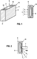
Figure 1 is a schematic view of an electrochemicalenergy storage device 5. Said electrochemicalenergy storage device 5 comprises a damage identification system 1. Infigure 1 , the electrochemicalenergy storage device 5 is shown from two different views. - The electrochemical
energy storage device 5 comprises ahousing 13. Thehousing 13 is provided with afirst terminal 14 and asecond terminal 15, wherein electrical power can be taken from the first terminal at 14 and thesecond terminal 15. At least parts of thehousing 13 are made of electroconductive material. - The damage identification system 1 comprises a
first contact element 2 and asecond contact element 4. Thesecond contact element 4 corresponds to a said outer surface of thehousing 13. Thefirst contact element 2 is provided inside thehousing 13 and is separated from the outer surface of the housing by an isolatingmember 3. The isolatingmember 3 might be a plastic film or a separate a jelly roll. Due to the isolatingmember 3, the first contact element is electrically isolated from thesecond contact element 3. - Both, the
first contact element 2 and thesecond contact element 4 are made of electroconductive material. As explained above, thesecond contact element 4 corresponds to the outer surface of thehousing 13, which preferably is made of electroconductive material. Thefirst contact element 2 preferably is made from a metal film. - Further, a
jelly roll 6 is provided inside thehousing 13. Thejelly roll 6 is made from adding a first electrode, a second electrode, and a separator and rolling those components to a flat shape. The electrodes are then connected to thefirst terminal 14 and thesecond terminal 15. Further, thesecond contact element 4, i.e. the outer surface of thehousing 13, is electrically connected to one of the electrodes of thejelly roll 6. Thefirst contact element 2 is electrically connected to a different electrical potential, particularly to a floating potential or a predefined potential, which is determined via a electrical resistance between a electric connection of thefirst contact element 2 and one of the electrodes of thejelly roll 6. - As can be seen from
figure 1 , the damage identification system 1 extends nearly over thewhole housing 13 such that nearly the whole electrochemicalenergy storage device 5 can be monitored regarding damages. Such a damage is shown infigure 2 . As can be seen fromfigure 2 , anail 7 penetrates the electrochemicalenergy storage device 5. Particularly, thenail 7 pierces through thehousing 13 and through isolatingmember 3. Therefore, the nail partly electrically connects thehousing 13, i.e. thesecond contact element 4, and thefirst contact element 2. Due to the connection of thefirst contact element 2 and thesecond contact element 4, damage of the electrochemicalenergy storage device 5 is identified. This will be explained afterwards. - Different solutions of the damage identification system 1 are shown in
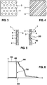
figure 3 to 5. Figures 3 and 5 are schematic views of an isolatingmember 3. The isolatingmember 3 comprisesseveral openings 8 which are shaped as through holes (figure 3 ) or as slots (figure 4 ). Theopenings 8 define predetermined breaking points such that the isolating member collapses as soon as an external force 200 (cf.figure 5 ) exceeds a predetermined value. Particularly, this predetermined value defines a boundary of a maximumexternal force 200 which is allowed to act on the electrochemicalenergy storage device 5. As soon this boundary is exceeded, there is a risk of damage of thejellyroll 6 which is provided inside the electrochemicalenergy storage device 5. -
Figure 5 shows an alternative damage identification system 1, which is not part of the claimed invention. On the left side, the damage identification system 1 is shown without external force, on the right side, anexternal force 200 acts on the damage identification system 1. - The damage identification system 1 comprises a
first connection element 2 and thesecond connection element 9, which both are made from metal foils. Between those metal foils, and isolatingmember 3 is shown infigure 3 or figure 4 is provided. Such a damage identification system 1 can then be provided on ahousing 13 of any electrochemicalenergy storage device 5. The main difference is thesecond connection element 9. Thesecond connection element 9 of the damage identification system 1 is a separate member and is not provided by the outer surface of thehousing 13 itself. Therefore, thehousing 13 might be fabricated from a material which is nonconductive. Another difference is the isolating member is 3, which finds predetermined breaking points such that no additional element is to appease the isolatingmember 3. - As soon as an
external force 200 exceeds the predetermined value, the isolatingmember 3 collapses and allows connection between thefirst contact element 2 and thesecond contact element 9. Again, due to such a connection, damage of the electrochemicalenergy storage device 5 is identified. -
Figure 6 is a diagram of the voltage of thefirst connection element 2 and the output voltage of the electrochemicalenergy storage device 5, which can be measured between thefirst terminal 14 and thesecond terminal 15. In this case, thesecond contact element jelly roll 6, i.e. to one of theterminals first contact element 2 is connected to a floating potential. As soon as a logical unit measures a voltage between thefirst contact element 2 and of the other electrode of thejelly roll 6, which is not connected to thesecond contact element first contact element 2 and asecond contact element - The voltage is plotted on the axis of ordinates and the time is plotted on the axis of abscissae in
figure 6 . It can be seen that theoutput voltage 300 of the electrochemicalenergy storage device 5 is constant untiltime 500 when penetration bynail 7 starts. Thetime 500 might also illustrate theexternal force 200 exceeding the predetermined value. Since the damage identification system 1 will be damaged first and electrochemicalenergy storage device 5 will be damaged afterwards, the voltage of thefirst contact element 2 which is denoted thisreference numeral 400 will increase before theoutput voltage 300 drops due to short circuits caused by the damage. Hence, saidincrease 700 of thevoltage 400 of thefirst contact element 2 indicates damage of the electrochemicalenergy storage device 5. This means, as soon asvoltage 400 shows such anincrease 700, countermeasures have to be started in order to avoid critical behavior of electrochemicalenergy storage device 5. - According to the invention, the
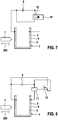
voltage 400 is employed to power alogical unit 10, which is shown infigure 7. Figure 7 shows a damage identification system 1 according to a first embodiment of the invention. As can be seen, thelogical unit 10, the electrochemicalenergy storage device 5, thefirst contact element 2, and thesecond contact element 9 set up a circuit for supplying power to thelogical unit 10. This means,logical unit 10 will only be supplied with electric power in case a contact between thefirst contact element 2 and thesecond contact element 9 is established. Such a contact would only be present in case of damage. Therefore,logical unit 10 is adapted to start measures to avoid critical cell behavior of the electrochemicalenergy storage device 5. In the embodiment shown infigure 7 , thelogical unit 10 actuates aswitch 12 for bridging the damaged electrochemicalenergy storage device 5. Therefore, the electrochemicalenergy storage device 5 is isolated such that a damage of the electrochemicalenergy storage device 5 will not have any influence to other energy sources like other electrochemical energy storage device. In an alternative solution, theunit 10 might activate a fast discharge device for discharging electrochemicalenergy storage device 5. - The
logical unit 10 also might be a fast discharge device without further logical elements. The fast discharge device is adapted to shortcut theelectrochemical storage device 5. In order to shortcut theelectrochemical storage device 5, the discharge device has to be activated by an electrical voltage. Since thefirst contact element 2 is electrically connected to one terminal of the electrochemicalenergy storage device 5 and the discharge device is electrically connected to another terminal of the electrochemicalenergy storage device 5 as well as to thesecond contact element 9, the discharge device is only prevented from being activated due to the isolatingmember 3. In case of damage, thefirst contact element 2 and thesecond contact element 9 come into contact such that the discharge device is activated and discharges theelectrochemical storage device 5. Hence, the discharge device, which helps to prevent catastrophic behavior of the electrochemicalenergy storage device 5 due to damage, is activated by the damage itself. No further logical elements are required. -
Figure 8 is a view of a second embodiment including an alternative solution oflogical unit 10. Again,figure 8 is a schematic view of damage identification system 1 according to the third embodiment. The difference to the first alternative shown infigure 7 is thelogical unit 11. Thelogical unit 11 is adapted to actuate aswitch 12 which again bridges the damaged electrochemicalenergy storage device 5. However, thelogical unit 11 will not be operated with only energy from electrochemicalenergy storage device 5 but rather comprises an additional power source. This also allows actuating switches 12 which require higher energy than that of the electrochemicalenergy storage device 5 is able to provide. Such a design is preferable in case a fast discharge device is provided as a semiconductor device. - The above-mentioned embodiments might be combined. Particularly, the different designs of
second contact element
Claims (5)
- Electrochemical energy storage device (5) comprising a damage identification system (1),
wherein said electrochemical energy storage device (5) includes a housing (13) at least part of which is made of electroconductive material and at least one battery cell, the battery cell being a jelly roll (6);
wherein said damage identification system (1) is provided on an outer surface of the jelly roll (6);
wherein said damage identification system (1) includes an electroconductive first contact element (2) and an electroconductive second contact element (4, 9) and an electrically isolating member (3) provided between the first contact element (2) and the second contact element (4, 9);
wherein the first contact element (2) and the second contact element (4, 9) have a plate like shape and are arranged in parallel to each other;
wherein the first contact element (2) and the second contact element (4, 9) are separated and/or electrically isolated from each other due to the isolating member (3);
wherein at least one outer surface of the housing (13) made of electroconductive material acts as the second contact element (4, 9) and said first contact element (2) is provided inside the housing (13);
wherein said damage identification system (1) includes a logical unit (10, 11) which is adapted to identify an electrical contact between the first contact element (2) and the second contact element (4, 9);
wherein the logical unit (10, 11) is arranged to identify a damage as soon as the electrical contact between the first contact element (2) and the second contact element (4, 9) is identified and to start countermeasures to avoid critical cell behavior of the electrochemical energy storage device (5);
wherein said battery cell and said first contact element (2) and said second contact element (4, 9) are connected to an open circuit for supplying electrical power to said logical unit (10, 11); and
wherein said open circuit can be closed due to the electrical contact between said first contact element (2) and said second contact element (4, 9). - Electrochemical energy storage device (5) according to claim 1, characterized in that the first contact element (2) and/or the second contact element (4, 9) are made of electroconductive foils.
- Electrochemical energy storage device (5) according to any of the previous claims, characterized in that the isolating member (3) is constructed to collapse and allow contact between the first contact element (2) and the second contact element (4, 9) as soon as an external force exceeds a predetermined value.
- Electrochemical energy storage device (5) according to any of the previous claims, characterized in that the logical unit (10, 11) comprises a fast discharge device for discharging the electrochemical energy storage device (5) and/or a bridging device for bridging the electrochemical energy storage device (5).
- Electrochemical energy storage device (5) according to any one of claim 2 to 4, characterized in that the first contact element (2) or the second contact element (4, 9) are directly or via an electric resistance connected to one electrode of the jelly roll (6).
Priority Applications (1)
| Application Number | Priority Date | Filing Date | Title |
|---|---|---|---|
| EP16205506.5A EP3340331B1 (en) | 2016-12-20 | 2016-12-20 | Damage identification system for electrochemical energy storages |
Applications Claiming Priority (1)
| Application Number | Priority Date | Filing Date | Title |
|---|---|---|---|
| EP16205506.5A EP3340331B1 (en) | 2016-12-20 | 2016-12-20 | Damage identification system for electrochemical energy storages |
Publications (2)
| Publication Number | Publication Date |
|---|---|
| EP3340331A1 EP3340331A1 (en) | 2018-06-27 |
| EP3340331B1 true EP3340331B1 (en) | 2021-04-14 |
Family
ID=57570858
Family Applications (1)
| Application Number | Title | Priority Date | Filing Date |
|---|---|---|---|
| EP16205506.5A Active EP3340331B1 (en) | 2016-12-20 | 2016-12-20 | Damage identification system for electrochemical energy storages |
Country Status (1)
| Country | Link |
|---|---|
| EP (1) | EP3340331B1 (en) |
Family Cites Families (3)
| Publication number | Priority date | Publication date | Assignee | Title |
|---|---|---|---|---|
| DE102011120505A1 (en) * | 2011-12-07 | 2013-06-13 | Daimler Ag | Battery for vehicle e.g. electric vehicle, has electrochemically active electrode sheet arrangement that is surrounded by foil-like sheath, and metallic layer which is projected between plastic layers and auxiliary electrode |
| DE102012005979B4 (en) | 2012-03-23 | 2013-11-07 | Fraunhofer-Gesellschaft zur Förderung der angewandten Forschung e.V. | Electric bridging element and energy storage with the bridging element |
| WO2014032768A1 (en) * | 2012-08-30 | 2014-03-06 | Li-Tec Battery Gmbh | Electrochemical energy storage cell and electrochemical energy storage device comprising at least one electrochemical energy storage cell of said type |
-
2016
- 2016-12-20 EP EP16205506.5A patent/EP3340331B1/en active Active
Non-Patent Citations (1)
| Title |
|---|
| None * |
Also Published As
| Publication number | Publication date |
|---|---|
| EP3340331A1 (en) | 2018-06-27 |
Similar Documents
| Publication | Publication Date | Title |
|---|---|---|
| US9774026B2 (en) | Apparatus for preventing over-charge for battery of vehicle | |
| CN108028152B (en) | Switching element, electronic component, and battery system | |
| JP5098197B2 (en) | Storage element module | |
| EP3843195B1 (en) | Thermal runaway detecting device, battery system, and thermal runaway detecting method of battery system | |
| US10050315B2 (en) | Battery module with fusible conductors | |
| KR20150038077A (en) | Battery having a thermal switch | |
| EP2171824A1 (en) | Method of deactivating faulty battery cells | |
| CN204857843U (en) | Battery short circuit protection component , battery module and car | |
| DE112013003186T5 (en) | Battery cell with flexible wireless temperature sensor | |
| CN107968231A (en) | Short switch, repid discharge unit, battery cell and working equipment | |
| KR20160113888A (en) | Battery pack | |
| KR20110129870A (en) | Protective unit for galvanic cells | |
| DE102014208627A1 (en) | battery cell | |
| EP3340331B1 (en) | Damage identification system for electrochemical energy storages | |
| EP3680955B1 (en) | Battery system | |
| US11223213B2 (en) | Battery system and electric vehicle using the same | |
| CN103443967A (en) | Electrochemical energy storage cell comprising a current interruption device | |
| CN215680806U (en) | Battery cell, battery pack and vehicle | |
| JP5561697B2 (en) | Storage cell with explosion-proof function, storage module with explosion-proof function | |
| CN212876189U (en) | Module flexible circuit board sampling connection structure | |
| EP3336933A1 (en) | System and method for operating a rechargeable battery unit and rechargeable battery unit | |
| JPH10188945A (en) | Lithium secondary battery | |
| EP3336956B1 (en) | Method for monitoring a discharge device of a battery | |
| EP3435445B1 (en) | Trigger device, safety apparatus, electric energy store device and method for triggering a safety device for an electric energy store unit | |
| EP3379610B1 (en) | Battery cell design for preventing internal short circuits from occurring and propagating |
Legal Events
| Date | Code | Title | Description |
|---|---|---|---|
| PUAI | Public reference made under article 153(3) epc to a published international application that has entered the european phase |
Free format text: ORIGINAL CODE: 0009012 |
|
| STAA | Information on the status of an ep patent application or granted ep patent |
Free format text: STATUS: THE APPLICATION HAS BEEN PUBLISHED |
|
| AK | Designated contracting states |
Kind code of ref document: A1 Designated state(s): AL AT BE BG CH CY CZ DE DK EE ES FI FR GB GR HR HU IE IS IT LI LT LU LV MC MK MT NL NO PL PT RO RS SE SI SK SM TR |
|
| AX | Request for extension of the european patent |
Extension state: BA ME |
|
| STAA | Information on the status of an ep patent application or granted ep patent |
Free format text: STATUS: REQUEST FOR EXAMINATION WAS MADE |
|
| 17P | Request for examination filed |
Effective date: 20181219 |
|
| RBV | Designated contracting states (corrected) |
Designated state(s): AL AT BE BG CH CY CZ DE DK EE ES FI FR GB GR HR HU IE IS IT LI LT LU LV MC MK MT NL NO PL PT RO RS SE SI SK SM TR |
|
| RAP1 | Party data changed (applicant data changed or rights of an application transferred) |
Owner name: GS YUASA INTERNATIONAL LTD. Owner name: ROBERT BOSCH GMBH |
|
| STAA | Information on the status of an ep patent application or granted ep patent |
Free format text: STATUS: EXAMINATION IS IN PROGRESS |
|
| 17Q | First examination report despatched |
Effective date: 20191002 |
|
| RAP1 | Party data changed (applicant data changed or rights of an application transferred) |
Owner name: GS YUASA INTERNATIONAL LTD. Owner name: ROBERT BOSCH GMBH |
|
| GRAP | Despatch of communication of intention to grant a patent |
Free format text: ORIGINAL CODE: EPIDOSNIGR1 |
|
| STAA | Information on the status of an ep patent application or granted ep patent |
Free format text: STATUS: GRANT OF PATENT IS INTENDED |
|
| INTG | Intention to grant announced |
Effective date: 20201113 |
|
| RIN1 | Information on inventor provided before grant (corrected) |
Inventor name: BUTZMANN, STEFAN Inventor name: FRIEDRICH, MARCO |
|
| GRAS | Grant fee paid |
Free format text: ORIGINAL CODE: EPIDOSNIGR3 |
|
| GRAA | (expected) grant |
Free format text: ORIGINAL CODE: 0009210 |
|
| STAA | Information on the status of an ep patent application or granted ep patent |
Free format text: STATUS: THE PATENT HAS BEEN GRANTED |
|
| AK | Designated contracting states |
Kind code of ref document: B1 Designated state(s): AL AT BE BG CH CY CZ DE DK EE ES FI FR GB GR HR HU IE IS IT LI LT LU LV MC MK MT NL NO PL PT RO RS SE SI SK SM TR |
|
| REG | Reference to a national code |
Ref country code: GB Ref legal event code: FG4D |
|
| REG | Reference to a national code |
Ref country code: CH Ref legal event code: EP |
|
| REG | Reference to a national code |
Ref country code: DE Ref legal event code: R096 Ref document number: 602016056011 Country of ref document: DE |
|
| REG | Reference to a national code |
Ref country code: IE Ref legal event code: FG4D |
|
| REG | Reference to a national code |
Ref country code: AT Ref legal event code: REF Ref document number: 1383250 Country of ref document: AT Kind code of ref document: T Effective date: 20210515 |
|
| REG | Reference to a national code |
Ref country code: LT Ref legal event code: MG9D |
|
| REG | Reference to a national code |
Ref country code: AT Ref legal event code: MK05 Ref document number: 1383250 Country of ref document: AT Kind code of ref document: T Effective date: 20210414 |
|
| REG | Reference to a national code |
Ref country code: NL Ref legal event code: MP Effective date: 20210414 |
|
| PG25 | Lapsed in a contracting state [announced via postgrant information from national office to epo] |
Ref country code: HR Free format text: LAPSE BECAUSE OF FAILURE TO SUBMIT A TRANSLATION OF THE DESCRIPTION OR TO PAY THE FEE WITHIN THE PRESCRIBED TIME-LIMIT Effective date: 20210414 Ref country code: BG Free format text: LAPSE BECAUSE OF FAILURE TO SUBMIT A TRANSLATION OF THE DESCRIPTION OR TO PAY THE FEE WITHIN THE PRESCRIBED TIME-LIMIT Effective date: 20210714 Ref country code: AT Free format text: LAPSE BECAUSE OF FAILURE TO SUBMIT A TRANSLATION OF THE DESCRIPTION OR TO PAY THE FEE WITHIN THE PRESCRIBED TIME-LIMIT Effective date: 20210414 Ref country code: FI Free format text: LAPSE BECAUSE OF FAILURE TO SUBMIT A TRANSLATION OF THE DESCRIPTION OR TO PAY THE FEE WITHIN THE PRESCRIBED TIME-LIMIT Effective date: 20210414 Ref country code: LT Free format text: LAPSE BECAUSE OF FAILURE TO SUBMIT A TRANSLATION OF THE DESCRIPTION OR TO PAY THE FEE WITHIN THE PRESCRIBED TIME-LIMIT Effective date: 20210414 Ref country code: NL Free format text: LAPSE BECAUSE OF FAILURE TO SUBMIT A TRANSLATION OF THE DESCRIPTION OR TO PAY THE FEE WITHIN THE PRESCRIBED TIME-LIMIT Effective date: 20210414 |
|
| PG25 | Lapsed in a contracting state [announced via postgrant information from national office to epo] |
Ref country code: PT Free format text: LAPSE BECAUSE OF FAILURE TO SUBMIT A TRANSLATION OF THE DESCRIPTION OR TO PAY THE FEE WITHIN THE PRESCRIBED TIME-LIMIT Effective date: 20210816 Ref country code: PL Free format text: LAPSE BECAUSE OF FAILURE TO SUBMIT A TRANSLATION OF THE DESCRIPTION OR TO PAY THE FEE WITHIN THE PRESCRIBED TIME-LIMIT Effective date: 20210414 Ref country code: NO Free format text: LAPSE BECAUSE OF FAILURE TO SUBMIT A TRANSLATION OF THE DESCRIPTION OR TO PAY THE FEE WITHIN THE PRESCRIBED TIME-LIMIT Effective date: 20210714 Ref country code: RS Free format text: LAPSE BECAUSE OF FAILURE TO SUBMIT A TRANSLATION OF THE DESCRIPTION OR TO PAY THE FEE WITHIN THE PRESCRIBED TIME-LIMIT Effective date: 20210414 Ref country code: SE Free format text: LAPSE BECAUSE OF FAILURE TO SUBMIT A TRANSLATION OF THE DESCRIPTION OR TO PAY THE FEE WITHIN THE PRESCRIBED TIME-LIMIT Effective date: 20210414 Ref country code: IS Free format text: LAPSE BECAUSE OF FAILURE TO SUBMIT A TRANSLATION OF THE DESCRIPTION OR TO PAY THE FEE WITHIN THE PRESCRIBED TIME-LIMIT Effective date: 20210814 Ref country code: GR Free format text: LAPSE BECAUSE OF FAILURE TO SUBMIT A TRANSLATION OF THE DESCRIPTION OR TO PAY THE FEE WITHIN THE PRESCRIBED TIME-LIMIT Effective date: 20210715 Ref country code: LV Free format text: LAPSE BECAUSE OF FAILURE TO SUBMIT A TRANSLATION OF THE DESCRIPTION OR TO PAY THE FEE WITHIN THE PRESCRIBED TIME-LIMIT Effective date: 20210414 |
|
| REG | Reference to a national code |
Ref country code: DE Ref legal event code: R097 Ref document number: 602016056011 Country of ref document: DE |
|
| PG25 | Lapsed in a contracting state [announced via postgrant information from national office to epo] |
Ref country code: RO Free format text: LAPSE BECAUSE OF FAILURE TO SUBMIT A TRANSLATION OF THE DESCRIPTION OR TO PAY THE FEE WITHIN THE PRESCRIBED TIME-LIMIT Effective date: 20210414 Ref country code: ES Free format text: LAPSE BECAUSE OF FAILURE TO SUBMIT A TRANSLATION OF THE DESCRIPTION OR TO PAY THE FEE WITHIN THE PRESCRIBED TIME-LIMIT Effective date: 20210414 Ref country code: DK Free format text: LAPSE BECAUSE OF FAILURE TO SUBMIT A TRANSLATION OF THE DESCRIPTION OR TO PAY THE FEE WITHIN THE PRESCRIBED TIME-LIMIT Effective date: 20210414 Ref country code: EE Free format text: LAPSE BECAUSE OF FAILURE TO SUBMIT A TRANSLATION OF THE DESCRIPTION OR TO PAY THE FEE WITHIN THE PRESCRIBED TIME-LIMIT Effective date: 20210414 Ref country code: CZ Free format text: LAPSE BECAUSE OF FAILURE TO SUBMIT A TRANSLATION OF THE DESCRIPTION OR TO PAY THE FEE WITHIN THE PRESCRIBED TIME-LIMIT Effective date: 20210414 Ref country code: SM Free format text: LAPSE BECAUSE OF FAILURE TO SUBMIT A TRANSLATION OF THE DESCRIPTION OR TO PAY THE FEE WITHIN THE PRESCRIBED TIME-LIMIT Effective date: 20210414 Ref country code: SK Free format text: LAPSE BECAUSE OF FAILURE TO SUBMIT A TRANSLATION OF THE DESCRIPTION OR TO PAY THE FEE WITHIN THE PRESCRIBED TIME-LIMIT Effective date: 20210414 |
|
| PLBE | No opposition filed within time limit |
Free format text: ORIGINAL CODE: 0009261 |
|
| STAA | Information on the status of an ep patent application or granted ep patent |
Free format text: STATUS: NO OPPOSITION FILED WITHIN TIME LIMIT |
|
| 26N | No opposition filed |
Effective date: 20220117 |
|
| PG25 | Lapsed in a contracting state [announced via postgrant information from national office to epo] |
Ref country code: IS Free format text: LAPSE BECAUSE OF FAILURE TO SUBMIT A TRANSLATION OF THE DESCRIPTION OR TO PAY THE FEE WITHIN THE PRESCRIBED TIME-LIMIT Effective date: 20210814 Ref country code: AL Free format text: LAPSE BECAUSE OF FAILURE TO SUBMIT A TRANSLATION OF THE DESCRIPTION OR TO PAY THE FEE WITHIN THE PRESCRIBED TIME-LIMIT Effective date: 20210414 |
|
| PG25 | Lapsed in a contracting state [announced via postgrant information from national office to epo] |
Ref country code: MC Free format text: LAPSE BECAUSE OF FAILURE TO SUBMIT A TRANSLATION OF THE DESCRIPTION OR TO PAY THE FEE WITHIN THE PRESCRIBED TIME-LIMIT Effective date: 20210414 Ref country code: IT Free format text: LAPSE BECAUSE OF FAILURE TO SUBMIT A TRANSLATION OF THE DESCRIPTION OR TO PAY THE FEE WITHIN THE PRESCRIBED TIME-LIMIT Effective date: 20210414 |
|
| REG | Reference to a national code |
Ref country code: CH Ref legal event code: PL |
|
| GBPC | Gb: european patent ceased through non-payment of renewal fee |
Effective date: 20211220 |
|
| REG | Reference to a national code |
Ref country code: BE Ref legal event code: MM Effective date: 20211231 |
|
| PG25 | Lapsed in a contracting state [announced via postgrant information from national office to epo] |
Ref country code: LU Free format text: LAPSE BECAUSE OF NON-PAYMENT OF DUE FEES Effective date: 20211220 Ref country code: IE Free format text: LAPSE BECAUSE OF NON-PAYMENT OF DUE FEES Effective date: 20211220 Ref country code: GB Free format text: LAPSE BECAUSE OF NON-PAYMENT OF DUE FEES Effective date: 20211220 |
|
| PG25 | Lapsed in a contracting state [announced via postgrant information from national office to epo] |
Ref country code: FR Free format text: LAPSE BECAUSE OF NON-PAYMENT OF DUE FEES Effective date: 20211231 Ref country code: BE Free format text: LAPSE BECAUSE OF NON-PAYMENT OF DUE FEES Effective date: 20211231 |
|
| PG25 | Lapsed in a contracting state [announced via postgrant information from national office to epo] |
Ref country code: LI Free format text: LAPSE BECAUSE OF NON-PAYMENT OF DUE FEES Effective date: 20211231 Ref country code: CH Free format text: LAPSE BECAUSE OF NON-PAYMENT OF DUE FEES Effective date: 20211231 |
|
| PG25 | Lapsed in a contracting state [announced via postgrant information from national office to epo] |
Ref country code: HU Free format text: LAPSE BECAUSE OF FAILURE TO SUBMIT A TRANSLATION OF THE DESCRIPTION OR TO PAY THE FEE WITHIN THE PRESCRIBED TIME-LIMIT; INVALID AB INITIO Effective date: 20161220 |
|
| PGFP | Annual fee paid to national office [announced via postgrant information from national office to epo] |
Ref country code: DE Payment date: 20221230 Year of fee payment: 7 |
|
| PG25 | Lapsed in a contracting state [announced via postgrant information from national office to epo] |
Ref country code: CY Free format text: LAPSE BECAUSE OF FAILURE TO SUBMIT A TRANSLATION OF THE DESCRIPTION OR TO PAY THE FEE WITHIN THE PRESCRIBED TIME-LIMIT Effective date: 20210414 |
|
| PG25 | Lapsed in a contracting state [announced via postgrant information from national office to epo] |
Ref country code: MK Free format text: LAPSE BECAUSE OF FAILURE TO SUBMIT A TRANSLATION OF THE DESCRIPTION OR TO PAY THE FEE WITHIN THE PRESCRIBED TIME-LIMIT Effective date: 20210414 |