EP3340124B1 - Sparse-coding mittels neuromorpher berechnung - Google Patents
Sparse-coding mittels neuromorpher berechnung Download PDFInfo
- Publication number
- EP3340124B1 EP3340124B1 EP17205542.8A EP17205542A EP3340124B1 EP 3340124 B1 EP3340124 B1 EP 3340124B1 EP 17205542 A EP17205542 A EP 17205542A EP 3340124 B1 EP3340124 B1 EP 3340124B1
- Authority
- EP
- European Patent Office
- Prior art keywords
- neurons
- synapses
- artificial
- neuromorphic
- snn
- Prior art date
- Legal status (The legal status is an assumption and is not a legal conclusion. Google has not performed a legal analysis and makes no representation as to the accuracy of the status listed.)
- Active
Links
Images








Classifications
-
- G—PHYSICS
- G06—COMPUTING OR CALCULATING; COUNTING
- G06N—COMPUTING ARRANGEMENTS BASED ON SPECIFIC COMPUTATIONAL MODELS
- G06N3/00—Computing arrangements based on biological models
- G06N3/02—Neural networks
- G06N3/06—Physical realisation, i.e. hardware implementation of neural networks, neurons or parts of neurons
- G06N3/063—Physical realisation, i.e. hardware implementation of neural networks, neurons or parts of neurons using electronic means
-
- G—PHYSICS
- G06—COMPUTING OR CALCULATING; COUNTING
- G06N—COMPUTING ARRANGEMENTS BASED ON SPECIFIC COMPUTATIONAL MODELS
- G06N3/00—Computing arrangements based on biological models
- G06N3/02—Neural networks
- G06N3/04—Architecture, e.g. interconnection topology
- G06N3/049—Temporal neural networks, e.g. delay elements, oscillating neurons or pulsed inputs
-
- G—PHYSICS
- G06—COMPUTING OR CALCULATING; COUNTING
- G06N—COMPUTING ARRANGEMENTS BASED ON SPECIFIC COMPUTATIONAL MODELS
- G06N3/00—Computing arrangements based on biological models
- G06N3/02—Neural networks
- G06N3/04—Architecture, e.g. interconnection topology
- G06N3/0495—Quantised networks; Sparse networks; Compressed networks
Definitions
- This disclosure relates in general to the field of computer systems and, more particularly, to neuromorphic computing.
- ANNs Artificial neural networks
- CNNs Convolution Neural Networks
- DNNs Deep Belief Networks
- Samuel Shapero et al. "Configurable hardware integrate and fire neurons for sparse approximation", NEURAL NETWORKS, GB, vol. 45, pages 134 - 143 , relates to sparse approximation as an important optimization problem in signal and image processing applications. It discloses a Hopfield-Network-like system of integrate and fire (IF) neurons as a solution, using the Locally Competitive Algorithm (LCA) to solve an overcomplete L1 sparse approximation problem. Also, a scalable system architecture is described, including IF neurons with a nonlinear firing function, and current-based synapses to provide linear computation.
- IF integrate and fire
- LCA Locally Competitive Algorithm
- the LIF model permits the development of multiple synaptic models including fast AMPA/GABA-A synapses with or without STDP learning, and slow NMDA synapses, spanning a range of different dynamic time constants. Its simple dynamics make it possible to expand the complexity of synaptic response, while the general-purpose design of SpiNNaker makes it possible if necessary to increase the neurodynamic accuracy with Izhikevich (or even Hodgkin-Huxley) neurons with some tradeoff in model size. Furthermore, the LIF model is a universally-accepted "standard" neural model that provides a good basis for comparisons with software simulations and introduces minimal risk of obscuring important synaptic effects due to unusual neurodynamics.
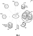
- FIG. 1 illustrates an unclaimed example computing system including a neuromorphic computing system 105, which may accept as inputs, data from one or a variety of sources.
- sources may include sensor devices (e.g., 110a-c).
- Such devices 110a-c may detect and/or measure attributes of an environment and generate sensor data describing or capturing characteristics of the environment.
- a given sensor may be configured to detect such characteristics as movement, weight, physical contact, temperature, wind, noise, light, computer communications, wireless signals, humidity, the presence of radiation or specific chemical compounds, among several other examples.
- Sensors may generate numerical data describing these attributes, audio data, photographic images, video, among other sensor data.
- Sources may additionally include data stores, such as databases of one or more computing systems (e.g., 115), which may aggregate data and/or generate additional data (e.g., from post processing of the aggregated data), such as in connection with a governmental, enterprise, scientific, or other entity or project.
- Data from the one or more sources e.g., 110a-c, 115, etc.
- results of produced by the neuromorphic computing system 105 may be additionally consumed, for instance, by an application system 120 hosting one or more other processes, programs, or applications.
- User endpoint devices such as personal computers and mobile devices, may additionally make use of the results generated from or in connection with a neuromorphic computing system 105, such as through the consumption of the results by one or more applications hosted by the user devices (e.g., 140, 145), presenting the results on a graphical user interface of the user device, among other examples.
- a neuromorphic computing system 105 may be provided as a service (e.g., over a network 130) to one or more other systems (e.g., 120, 140, 145).
- a neuromorphic computing system 105 may additionally utilize inputs generated by remote systems (e.g., an Internet of Things (IoT) network composed of multiple sensor devices (e.g., 110a-c).
- remote systems e.g., an Internet of Things (IoT) network composed of multiple sensor devices (e.g., 110a-c).
- IoT Internet of Things
- the functionality of a neuromorphic computing system 105 may be integrated with any one of the other example systems (e.g., 110a-c, 115, 120, 130, 140, 145, etc.).
- a wearable device or IoT device may be provided with neuromorphic computing resources to operate directly on inputs generated by a sensor of the device.
- an application or service may be provided (e.g., by application server system 120), which includes and makes use of neuromorphic computing resources, among a variety of other examples and use cases.
- neuromorphic computing systems may utilized to support or implement products or services based on or utilizing artificial intelligence, including digital personal assistants, chat bots, video games, self-driving cars, robots, and other examples.
- servers can include electronic computing devices operable to receive, transmit, process, store, or manage data and information associated with the computing environment 100.
- computer can include any suitable processing apparatus.
- elements shown as single devices within the computing environment 100 may be implemented using a plurality of computing devices and processors, such as server pools including multiple server computers.
- any, all, or some of the computing devices may be adapted to execute any operating system, including Linux, UNIX, Microsoft Windows, Apple OS, Apple iOS, Google Android, Windows Server, etc., as well as virtual machines adapted to virtualize execution of a particular operating system, including customized and proprietary operating systems.
- any operating system including Linux, UNIX, Microsoft Windows, Apple OS, Apple iOS, Google Android, Windows Server, etc.
- virtual machines adapted to virtualize execution of a particular operating system, including customized and proprietary operating systems.
- FIG. 1 is described as containing or being associated with a plurality of elements, not all elements illustrated within computing environment 100 of FIG. 1 may be utilized in each alternative implementation of the present disclosure. Additionally, one or more of the elements described in connection with the unclaimed examples of FIG. 1 may be located external to computing environment 100, while in other instances, certain elements may be included within or as a portion of one or more of the other described elements, as well as other elements not described in the illustrated implementation. Further, certain elements illustrated in FIG. 1 may be combined with other components, as well as used for alternative or additional purposes in addition to those purposes described herein.
- Neuromorphic computing may involve the use of very-large-scale integration (VLSI) systems containing electronic circuits to mimic neuro-biological architectures present in the nervous system to imbue computing systems with "intelligence".
- VLSI very-large-scale integration
- a desirable feature of neuromorphic computing is its ability to autonomously extract high dimensional spatiotemporal features from raw data streams that can reveal the underlying physics of the system being studied thus making them amenable for rapid recognition. Such features may be useful in big data and other large scale computing problems.
- neuronal-inspired algorithms may be characterized by hierarchical and feedforward organization where the artificial neurons or processing units in lower levels of the hierarchy have small receptive fields that serve as input filters sensitive to low level features. The outputs of these filters may be then fed to the next level, pooling information across several previous level filters. This process is repeated until a classifier is trained to detect objects of interest in the final layer.
- the salient aspect of such algorithms is that neuronal activity at increasingly higher levels abstracts more general and complex features.
- the pooling operation is beneficial for extracting features that are often transformation invariant, thus forming a stable internal representation.
- Such solutions may be successfully applied to challenging problems in machine learning including object recognition and other examples.
- deep learning models e.g., feed forward neural networks utilizing nonlinear activation functions
- feed forward neural networks utilizing nonlinear activation functions may bear resemblance in architecture to their biological counterparts, they have failed to explain recognition in general owing to its inability to generalize well to novel situations with limited training examples.
- pooling operations result in seeing wholes at the expense of the parts, as is evident in target-distractor recognition tasks, where both target and distractor features at the lower level are pooled at the higher levels.
- Such models require millions of examples in order to learn to "average" out distractors, while extracting the most reliable target features.
- the resulting representation is brittle because the distractor set is virtually infinite, and thus even after a large number of training examples a new distractor can still cause false alarms. Additionally, all units and parameters at all levels of the network are engaged in representing any given input, and are adjusted together during learning.
- an improved neuromorphic computing platform may be provided which adopts an energy efficient architecture inspired by the brain that is both scalable and energy efficient while also supporting multiple modes of learning on-chip.
- neuromorphic computing hardware may be connected to, integrated with, or otherwise used together with general computing hardware (e.g., a CPU) to support a wide range of traditional workloads as well as non-traditional workloads such as dynamic pattern learning and adaptation, constraint satisfaction and sparse coding using a single compute platform.
- general computing hardware e.g., a CPU
- Such a solution may leverage understandings from biological neuroscience regarding the improvement of system level performance by leveraging various learning modes such as unsupervised, supervised and reinforcement using spike timing and asynchronous computation, among other example features and considerations.
- a neuromorphic computing system adopts a multicore architecture where each core houses the computing elements including neurons, synapses with on-chip learning capability, and local memory to store synaptic weights and routing tables.
- FIG. 2A is a simplified block diagram 200 illustrating an unclaimed example of at least a portion of such a neuromorphic computing device 205.
- a device 205 may be provided with a network 210 of multiple neural network cores interconnected by an on-device network such that multiple different connections may be potentially defined between the cores.
- a network 210 of spiking neural network cores may be provided in the device 205 and may each communicate via short packetized spike messages sent from core to core over the network channels.
- Each core may possess processing and memory resources and logic to implement some number of primitive nonlinear temporal computing elements, such as multiple (e.g., 1000+) distinct artificial neurons (referred to herein as "neurons").
- each core may be capable of concurrently implementing multiple neurons such that the collection of neuromorphic cores may implement many multiples of neurons using the device.
- a neuromorphic computing device 205 may additionally include a processor 220 and system memory 225 to implement one or more components to manage and provide functionality of the device.
- a system manager 230 may be provided to manage global attributes and operations of the device (e.g., attributes affecting the network of cores 210, multiple cores in the network, interconnections of the device 205 with other devices, manage access to global system memory 225, among other potential examples).
- a system manager 230 may manage the definition and provisioning of a specific routing tables to the various routers in the network 210, orchestration of a network definition and attributes (e.g., weights, decay rates, etc.) to be applied in the network, core synchronization and time multiplexing management, routing of inputs to the appropriate cores, among other potential functions.
- a network definition and attributes e.g., weights, decay rates, etc.
- a neuromorphic computing device 205 may additionally include a programming interface 235 through which a user or system may specify a neural network definition to be applied (e.g., through a routing table and individual neuron properties) and implemented by the mesh 210 of neuromorphic cores.
- a software-based programming tool may be provided with or separate from the neuromorphic computing device 205 through which a user may provide a definition for a particular neural network to be implemented using the network 210 of neuromorphic cores.
- the programming interface 235 may take the input of the programmer to then generate corresponding routing tables and populate local memory of individual neuromorphic cores (e.g., 215) with the specified parameters to implement a corresponding, customized network of artificial neurons implemented by the neuromorphic cores.
- a neuromorphic computing device 205 may advantageously interface with and interoperate with other devices, including general purpose computing devices, to realize certain applications and use cases.
- external interface logic 240 may be provided in some cases to communicate (e.g., over one or more defined communication protocols) with one or more other devices.
- An external interface 240 may be utilized to accept input data from another device or external memory controller acting as the source of the input data.
- An external interface 240 may be additionally or alternatively utilized to allow results or output of computations of a neural network implemented using the neuromorphic computing device 205 to be provided to another device (e.g., another general purpose processor implementing a machine learning algorithm) to realize additional applications and enhancements, among other examples.
- a block diagram 200b is shown illustrating a portion of a network fabric interconnecting multiple neuromorphic cores (e.g., 215a-d).
- a number of neuromorphic cores e.g., 215a-d
- each core being interconnected by a network including a number of routers (e.g., 250).
- each neuromorphic core e.g., 215a-d
- each neuromorphic core may be connected to a single router (e.g., 250) and each of the routers may be connected to two or more other routers to form a manycore mesh, allowing each of the neuromorphic cores to interconnect with each other neuromorphic core in the device.
- the router network of the device may similarly enable connections, or artificial synapses (or, simply, "synapses"), to be defined between any two of the potentially many (e.g., 30,000+) neurons defined using the network of neuromorphic cores provided in a neuromorphic computing device.
- FIG. 2C shows a block diagram 200c illustrating internal components of one example implementation of a neuromorphic core 215.
- a single neuromorphic core may implement some number of neurons (e.g. 1024) that share architectural resources of the neuromorphic core in a time-multiplexed manner.
- each neuromorphic core 215 may include a processor block 255 capable of performing arithmetic functions and routing in connection with the realization of a digitally implemented artificial neuron, such as explained herein.
- Each neuromorphic core 215 may additionally provide local memory in which a routing table may be stored and accessed for a neural network, accumulated potential of each soma of each neuron implemented using the core may be tracked, parameters of each neuron implemented by the core may be recorded, among other data and usage.
- Components, or architectural resources, of a neuromorphic core 215 may further include an input interface 265 to accept input spike messages generated by other neurons on other neuromorphic cores and an output interface 270 to send spike messages to other neuromorphic cores over the mesh network.
- routing logic for the neuromorphic core 215 may be at least partially implemented using the output interface 270.
- a core may implement multiple neurons within an example SNN and some of these neurons may be interconnected.
- spike messages sent between the neurons hosted on the particular core may forego communication over the routing fabric of the neuromorphic computing device and may instead by managed locally at the particular neuromorphic core.
- Each neuromorphic core may additionally include logic to implement, for each neuron 275, an artificial dendrite 280 and an artificial soma 185 (referred to herein, simply, as “dendrite” and “soma” respectively).
- the dendrite 280 may be a hardware-implemented process that receives spikes from the network.
- the soma 285 may be a hardware-implemented process that receives each dendrite's accumulated neurotransmitter amounts for the current time and evolves each dendrite and soma's potential state to generate outgoing spike messages at the appropriate times.
- a dendrite 280 may be defined for each connection receiving inputs from another source (e.g., another neuron).
- the dendrite process 280 may receive and handle spike messages as they serially arrive in time-multiplexed fashion from the network. As spikes are received, the neuron's activation (tracked using the soma 285 (and local memory 260)) may increase. When the neuron's activation exceeds a threshold set for the neuron 275, the neuron may generate a spike message that is propagated to a fixed set of fanout neurons via the output interface 270. The network distributes the spike messages to all destination neurons, and in response to those neurons, in turn, update their activations in a transient, time-dependent manner, and so on, potentially causing the activation of some of these destination neurons to also surpass corresponding thresholds and trigger further spike messages, as in real biological neural networks.
- a neuromorphic computing device may reliably implement a spike-based model of neural computation.
- Such models may also be referred to as Spiking Neural Networks (SNNs).
- SNNs also incorporate the concept of time. For instance, in an SNN, communication occurs over event-driven action potentials, or spikes, that convey no explicit information other than the spike time as well as an implicit source and destination neuron pair corresponding to the transmission of the spike. Computation occurs in each neuron as a result of the dynamic, nonlinear integration of weighted spike input.
- recurrence and dynamic feedback may be incorporated within an SNN computational model.
- a variety of network connectivity models may be adopted to model various real world networks or relationships, including fully connected (all-to-all) networks, feed-forward trees, fully random projections, "small world” networks, among other examples.
- a homogeneous, two-dimensional network of neuromorphic cores such as shown in the unclaimed example of FIGS. 2A-C may advantageously supports all of these network models. As all cores of the device are connected, all neurons defined in the cores are therefore also fully connected through some number of router hops.
- the device may further include fully configurable routing tables to define a variety of different neural networks by allowing each core's neurons to distribute their spikes to any number of cores in the mesh to realize fully arbitrary connectivity graphs.
- a system capable of supporting SNNs such as the very large scale integration (VLSI) hardware device illustrated in FIGS. 2A-C
- VLSI very large scale integration
- high speed and reliable circuits may be provided to implement SNNs to model the information processing algorithms as employed by the brain, but in a more programmable manner.
- a neuromorphic processor device may provide the capability to rapidly reprogram all neural parameters.
- a single neuromorphic processor may be utilized to realize a broader range of behaviors than those provided by a single slice of biological brain tissue. This distinction may be realized by adopting a neuromorphic processor with neuromorphic design realizations that differ markedly from those of the neural circuits found in nature.
- a neuromorphic processor may utilize time-multiplexed computation in both the spike communication network and the neuron machinery of the device to implement SNNs. Accordingly, the same physical circuitry of the processor device may be shared among many neurons to realize higher neuron density. With time multiplexing, the network can connect N cores with O(N) total wiring length, whereas discrete point-to-point wiring would scale as O(N 2 ), realizing a significant reduction in wiring resources to accommodate planar and non-plastic VLSI wiring technologies, among other examples.
- time multiplexing may be implemented through dense memory allocation, for instance, using Static Random Access Memory (SRAM), with shared buses, address decoding logic, and other multiplexed logic elements. State of each neuron may be stored in the processor's memory, with data describing each neuron state including state of each neuron's collective synapses, all currents and voltages over its membrane, among other example information (such as configuration and other information).
- SRAM Static Random Access Memory
- a neuromorphic processor may adopt a "digital" implementation that diverts from other processors adopting more "analog” or “isomorphic” neuromorphic approaches.
- a digital implementation may implement the integration of synaptic current using digital adder and multiplier circuits, as opposed to the analog isomorphic neuromorphic approaches that accumulate charge on capacitors in an electrically analogous manner to how neurons accumulate synaptic charge on their lipid membranes.
- the accumulated synaptic charge may be stored, for instance, for each neuron in local memory of the corresponding core.
- reliable and deterministic operation may be realized by synchronizing time across the network of cores such that any two executions of the design, given the same initial conditions and configuration, will produce identical results.
- Asynchrony may be preserved at the circuit level to allow individual cores to operate as fast and freely as possible, while maintaining determinism at the system level.
- the notion of time as a temporal variable may be abstracted away in the neural computations, separating it from the "wall clock" time that the hardware utilized to perform the computation.
- a time synchronization mechanism may be provided that globally synchronizes the neuromorphic cores at discrete time intervals. The synchronization mechanism allows the system to complete a neural computation as fast as the circuitry allows, with a divergence between run time and the biological time that the neuromorphic system models.
- the neuromorphic mesh device may begin in an idle state with all neuromorphic cores inactive. As each core asynchronously cycles through its neurons, it generates spike messages that the mesh interconnect routes to the appropriate destination cores containing all destination neurons. As the implementation of multiple neurons on a single neuromorphic core may be time-multiplexed, a time step may be defined in which all spikes involving the multiple neurons may be processed and considered using the shared resources of a corresponding core.
- the cores may, in some implementations, communicate (e.g., using a handshake) with neighboring cores using synchronization messages to flush the mesh of all spike messages in flight, allowing the cores to safely determine that all spikes have been serviced for the time step. At that point all cores may be considered synchronized, allowing them to advance their time step and return to the initial state and begin the next time step.
- a device e.g., 205) implementing a mesh 210 of interconnected neuromorphic cores may be provided, with the core implementing potentially multiple artificial neurons capable of being interconnected to implement an SNN.
- Each neuromorphic core e.g., 215) may provide two loosely coupled asynchronous processes: an input dendrite process (e.g., 280) that receives spikes from the network and applies them to the appropriate destination dendrite compartments at the appropriate future times, and an output soma process (e.g., 285) that receives each dendrite compartment's accumulated neurotransmitter amounts for the current time and evolves each dendrite and soma's membrane potential state, generating outgoing spike messages at the appropriate times (e.g., when a threshold potential of the soma has been reached).
- the dendrite and soma names used here only approximate the role of these functions and should not be interpreted too literally.
- Spike messages may identify a particular distribution set of dendrites within the core.
- Each element of the distribution set may represent a synapse of the modeled neuron, defined by a dendrite number, a connection strength (e.g., weight W ), a delay offset D, and a synapse type, among potentially other attributes.
- each weight W i may be added to the destination dendrite's total current u scheduled for servicing at time step T+D i in the future. While not handling input spikes, the dendrite process may serially service all dendrites sequentially, passing the total current u for time T to the soma stage.
- the soma process receives an accumulation of the total current u received via synapses mapped to specific dendritic compartments of the soma.
- each dendritic compartment maps to a single neuron soma.
- a neuromorphic core mesh architecture may additionally support multicompartment neuron models.
- Core memory may store the configured attributes of the soma and the state of the soma, the total accumulated potential at the soma, etc.
- synaptic input responses may be modeled in the core with single-time-step current impulses, low state variable resolution with linear decay, and zero-time axon delays, among other example features.
- neuron models of the core may be more complex and implement higher resolution state variables with exponential decay, multiple resting potentials per ion channel type, additional neuron state variables for richer spiking dynamics, dynamic thresholds implementing homeostasis effects, and multiple output spike timer state for accurate burst modeling and large axonal delays, among other example features.
- the soma process implemented by each of the neuromorphic cores may implement a simple current-based Leaky Integrate-and-Fire (LIF) neuron model.
- LIF Leaky Integrate-and-Fire
- a neuromorphic computing device may be provided to define a spiking neural network architecture abstraction that can efficiently solve a class of sparse coding problems.
- the basic computation units in the architecture may be neurons and the neurons may be connected by synapses, which define the topology of the neural network. Synapses are directional, and neurons are able to communicate to each other if a synapse exists.
- FIG. 3A is a simplified block diagram 300a illustrating a simple example neural network, including neurons 305, 310, 315, 320 connected by synapses. The synapses allow spike messages to be transmitted between the neurons. For instance, neuron 305 may receive spike messages generated by neurons 315, 320.
- synapses may be directional. In some cases, a network and corresponding synapses may be defined such that a neuron (e.g., 315) only receives or transmits to some of the other neuron (e.g., 305), while in synapses may be defined which connect the neuron bi-directionally with other neurons (e.g., between neurons 315, 320) to create a feedback loop, among other examples.
- An example neuromorphic computing device may adopt leaky integrate-and-fire neurons and current-based synapses. Accordingly, the dynamics of the network may be driven by the evolution of the state variables in each neuron.
- each neuron has two types of state variables: one membrane potential v ( t ), and one or more dendritic current(s) u 1 ( t ) ,... to u s ( t ) .
- An individual neuron's dynamics may be defined by the following continuous-time differential equations (1) - (3).
- Equation (1) depicts the dynamics of dendritic current.
- Each dendritic current variable may be defined to decay exponentially over time, according to its respective decay time constant ⁇ s k .
- the dendritic current may be linearly summed to control the integration of the membrane potential (as shown in Equation (2)). Similar to dendritic current, the membrane potential may also be subject to exponential decay with a separate membrane potential time constant ⁇ m .
- Equation (3) may define the spiking event of a neuron. When a neuron's membrane potential reaches a particular threshold voltage ⁇ defined for the neuron, the neuron (e.g., through its soma process) resets the membrane potential to zero, and sends out a spike to neighboring neurons connected by corresponding synapses.
- the dendrite process of each neuron can be defined such that a spike arrival causes a change in the dendritic current.
- Spikes are transmitted along synapses and the incoming synapse may be defined to be associated with one dendritic current variable, e.g., using the dendritic compartment.
- each spike arrival changes only one dendritic current u k ( t ) .
- the change may be defined to manifest as an instantaneous jump in u k ( t ) , such as defined in Equation (4), based on the magnitude of the synaptic weight w ij .
- u k t + u k t ⁇ + w ij
- ⁇ s 1 in addition to the state variables of a neuron, there are several other configurable parameters, including the time constant of individual dendritic compartment ⁇ s 1 , ... , ⁇ s s , a single ⁇ m , ⁇ ,I bias for each neuron, and a configurable weight value w ij for each synapse from neuron j to i , which may be defined and configured to model particular networks.
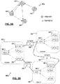
- FIG. 3B shows an example illustrating synaptic connections between individual dendrites of neurons in a network, and the parameters that may be defined for these neurons and synapses.
- neurons 325, 330, 335 implemented by cores of an example neuromorphic computing device are shown, together with synapses defined (e.g., using a routing table) for interconnections within a neural network implemented using the neurons 325, 330, 335.
- Each neuron may include one or more dendrite (processes) (e.g., 340, 360, 375, 380) and a respective soma (process) (e.g., 345, 365, 385).
- Spike messages received at each of the dendrites of a respective neuron may contribute to the activation potential of the soma, with the soma firing a spike message when the soma-specific potential threshold is reached.
- a synapse connects two neurons. The synapse may effectively connect the soma of a sending neuron to one of the dendrites of the receiving neuron. Further, each synapse may be assigned a respective weight (e.g., 350, 355, 370). In the example of FIG. 3B , a synapse with a first weight 350 may connect soma 345 of neuron 325 with dendrite 360 of neuron 330.
- Soma 345 of neuron 325 may additionally connect to neuron 380 via another synapse (with potentially a different weight 355). Soma 365 of neuron 330 may also connect to neuron 380 via a respective synapse 370. In some cases, multiple neurons may connect to a particular neuron at the same dendrite of the particular neuron. In such instances, the parameters defined for this one dendrite will govern the effect of the incoming spike messages from each of the connected neurons. In other cases, such as shown in FIG.
- different neurons may connect to the same neuron (e.g., 335) but at different dendrites (e.g., 375 and 380 respectively), allowing different parameters (defined for each of these dendrites (e.g., 375, 380)) to affect the respective spikes arriving from each of these different neurons (e.g., 325, 330).
- parameters may be defined for each of the somas (e.g., 345, 365, 385) of each of the various neurons (e.g., 325, 330, 335) defined in the network, allowing these parameters to likewise contribute to the overall configurability of the neural network implemented using the neuromorphic computing device, among other examples.
- neuron parameters may include such examples as a synaptic decay time constant ⁇ s , bias current I b :, firing potential threshold ⁇ , and synaptic weight w ij from neuron to neuron (i.e., from neuron j to neuron i). These parameters may be set by a programmer of the neural network, for instance, to configure the network to model a real network, matrix, or other entity. Further, neuron state variables may be defined to include time-varying current u ( t ) and voltage v ( t ) and represented by corresponding ordinary differential equations.
- Equations (1) - (4) defines spiking neural network dynamics in continuous time.
- a network of neuromorphic cores is provided (such as shown and discussed in connection with FIGS. 2A-2C ), with each of the neuromorphic cores possessing processor resources and logic executable to solve the continuous network dynamics using first-order techniques, such as by approximating SNN dynamics using discrete time steps.
- a virtual global clock is provided in the neuromorphic computing device to coordinate the time-stepped updates of individual neurons at each core.
- every neuron implemented by the network of cores can adjust (e.g., in a time-multiplexed manner) its respective state variables, and will do so no more than once per time step.
- each spike message generated by a neuron in the SNN may be guaranteed to be delivered within a corresponding time step.
- a digital approximation may be realized as follows.
- representations 400a-c are provided of interconnected artificial neurons within unclaimed example spiking neural networks.
- an input current I 1 is provided to a first neuron 405, resulting in an increase in the potential of the neuron 405 until a threshold potential is reached and a spike message is generated by neuron 405.
- a constant current input is applied at the first neuron, a predictable spike output at a fixed spiking rate ⁇ 1 (expressing the rate of spike messages generated over time)
- This spike message output (e.g., 410) may be then provided via one or more outbound synapses connecting the first neuron 405 to one or more other neurons (e.g., 415).
- a synaptic weight w 21 may be defined for the artificial synapse connecting the two neurons 405, 415.
- the second neuron 415 may receive the spike inputs 410 generated by the first neuron 405 causing spike messages to likewise be generated by the second neuron 405 when the internal membrane potential threshold of the second neuron is met, resulting a neuron spiking rate ⁇ 2 of the second neuron 415.
- Parameter may be defined (e.g., via user or other programmatic inputs) to define parameters for each neuron in a network including a synaptic decay time constant ( ⁇ s ), bias current (I b ), synaptic weight from neuron j to neuron i ( w ij ) , membrane firing threshold ( ⁇ ), among other examples.
- State of each neuron may be calculated and maintained (by corresponding neuromorphic cores implementing the neurons).
- synaptic weight, input, and spiking rate may be leveraged to define SNNs to model numerical matrices and perform matrix arithmetic using the SNN.
- a collection of M neurons may be connected to another collection of N neurons, such that a unidirectional synaptic connection is defined from each one of the M neurons to each one of the N neurons, as illustrated in FIG 4B .
- An input I 1 may be defined to be provided to the first layer of M neurons, such that the input defines an M x 1 vector I 1 .
- Respective synaptic weights w nm may be defined for each of the synapses connecting neurons in the first row to neurons in the second row, as in the unclaimed example of FIG. 4B .
- the M x N number of synapses and corresponding weights may be represented as an N x M matrix W of the synaptic weights.
- the respective spiking rates ⁇ 2 of the top layer of neurons may be based on the spiking rates ⁇ 1 of the neurons in the first layer.
- An N x 1 vector ⁇ 2 may express the collected spiking rates of the second (top) layer of neurons in the network, while an M x 1 vector M x 1 vector ⁇ 1 may express the collected spiking rates of the first (bottom) layer of neurons.
- a 2 WI 1
- the observed spiking rate of the top layer may represent the product of the inverse of the matrix W multiplied with vector I 1 .
- the SNN can "perform" the matrix-vector multiplication of the numerical matrix and numerical vector based on proper programming of a SNN network (similar to the unclaimed example shown in FIG. 4B ).
- a programmable neuromorphic computing device may be programmed to define the M + N neurons and synapses connecting them with weights corresponding to the matrix to be multiplied by the SNN solver.
- recurrent connections may be defined for an M x 1 vector of artificial neurons in an SNN.
- a recurrently connected layer of neurons may be defined with respective synaptic weights represented by an M x M matrix W .
- An input provided to the M neurons may be represented as a vector I 1 , which may produce spikes (fed recurrently to the neurons in the network) firing at respective spiking rates (represented by an M x 1 vector ⁇ 1 ).
- a configurable neuromorphic computing device may be programmed to implement a recurrently connected network of artificial neurons with synaptic weights corresponding to values of a matrix W and may be provided with a vector input with values corresponding to a vector I 1 to solve for the product of the inverse of the matrix W and the vector I 1 , as illustrated in FIG. 4C .
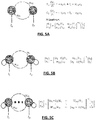
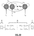
- FIGS. 5A-5D block diagrams 500a-d are shown illustrating the types of synaptic connections that may utilize by neural network designers to construct SNNs to model various matrix calculations including matrix inversions, matrix multiplication, and others.
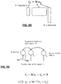
- FIG. 5A illustrates a simple two-neuron case.
- the firing thresholds of the neurons may be configured as ⁇ 1 and ⁇ 2 , and the inputs configured as I 1 and I 2 .
- the two directional synapses connecting the two neurons have weights W 12 and W 21 , with synaptic decay time constant ⁇ 1 and ⁇ 2 .
- the firing rates of the neurons x 1 and x 2 correspond to a solution of an inverse problem.
- FIG. 5A illustrates a simple two-neuron case.
- the firing thresholds of the neurons may be configured as ⁇ 1 and ⁇ 2 , and the inputs configured as I 1 and I 2 .
- the two directional synapses connecting the two neurons have weights W 12 and W 21 , with synapt
- FIG. 5B shows an extension of the unclaimed example of FIG. 5A by adding synapses connecting a neuron to itself (i.e., recurrently), for which the steady state firing rate is still a solution of another inverse problem.
- FIG. 5B thereby shows an alternative to FIG. 5A for constructing a spiking neural network to solve an inverse problem.
- FIG. 5C shows that the unclaimed example of FIG. 5B can be generalized to an arbitrary dimension of N neurons, solving an NxN inverse problem, with FIG. 5D showing further generalizations by adding inhibitory synapses between a pair of neurons, allowing more possible configurations to solve an inverse problem.
- 5D provides an SNN configured (e.g., using a configurable digital neuromorphic computing architecture) to solve a matrix inversion problem.
- SNN may be used to solve classes of matrix inversion problems (e.g., manifesting in various scientific computing applications) in an approximate fashion but with high throughput (using small ⁇ 's) and high energy efficiency (due to spike-based (i.e., sporadic) inter-node communication), among other example advantages.
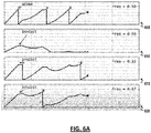
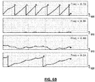
- FIGS. 6A-6B illustrate signal diagrams illustrating spiking behavior observed at four nodes (e.g., 605, 610, 615, 620) in an SNN implemented using a neuromorphic computing device employing a network of neuromorphic core elements.
- the neuromorphic computing device may be programmed to implement a particular SNN that includes a particular number of artificial neurons implemented using the neuromorphic cores.
- the particular SNN may be further implemented by defining the synaptic connections between the artificial neurons. Parameters of the neurons may be set, including decay rates of the synapses and somas, and weights may be assigned to each synapse, among other configurable parameters to implement the particular SNN.
- a respective input current or signal may be provided at at least a subset of the neurons in the particular SNN.
- various spike messages may be generated by the various neurons in the SNN based on their respective parameters, the particular network of synapses connecting the neurons, weights applied to the synapses, etc. Accordingly, the spiking behavior of the neurons may vary across the network. For instance, neuron 605 may spike immediately and continue spiking at semi-regular intervals. Neuron 610, on the other hand may struggle to compile sufficient membrane potential to ever trigger and sent a spiking message on the SNN.
- FIG. 6A and 6B further show a spiking frequency, or spiking rate measured by observing spike messages generated by the individual neurons 605, 610, 615, 620.
- a spiking rate of 0.50 may be measured for neuron 605, while rates of 0.00, 0.33, and 0.17 are measured for neurons 610, 615, 620, respectively.
- the spiking rate of each neuron has begun to converge toward a particular value.
- the spiking rate of neuron 605 is measured at 0.78
- the spiking rate of neuron 620 is measured at 0.24
- the spiking rates of both neurons 610 and 615 are converging to zero.
- the values shown in the example of FIG. 6B may approximate the "final" equilibrium spiking rates of these four neurons, were the SNN permitted to run infinitely.
- the equilibrium spiking rate values shown in FIGS. 6A-6B are provided as an example only and represent values unique to the particularly configured SNN and neurons in this example. The spiking rates of other SNNs and neurons may be expected to be quite different from those shown in this particular example.
- an SNN will reach an equilibrium or steady state after being allowed to run for a time and that spiking rates observed in the SNN may similarly approximate respective steady state values after some period of time (e.g., after some number of time steps).
- Such equilibrium values may be leveraged in connection with the solving of various matrix inversion problems using an SNN.
- spiking rates may be measured at at least a subset of neurons in an SNN and these values, when at steady state (or at an instance considered to approximate the steady state of the SNN), may represent a result vector to be solved for in the matrix inversion problem.
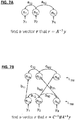
- a recurrently connected SNN may be programmed and implemented such that the values of matrix A (e.g., a 12 , a N2 , etc.) are mapped to corresponding synapses defined for the SNN.
- a recurrently connected SNN may provide a layer of neurons where each neuron layer connects to the other bi-directionally (i.e., by two synapses each, one synapse in each direction).
- the values of the vector y may be adopted as the inputs (e.g., y 1 , y 2 , y N , etc.) to be provided to the N neurons (e.g., n 1 , n 2 , n N , etc.) provided in the programmed SNN.
- the SNN may then be allowed to run with the input vector y applied to the SNN and the respective spiking rates (e.g., r 1 , r 2 , r N , etc.) of the neurons (e.g., n 1 , n 2 , n N , etc.) may be observed (e.g., using a monitoring program through an interface of the neuromorphic computing device, by a management utility local to and executed on the neuromorphic computing device itself, among other examples).
- the SNN may be permitted to run for a time until it is determined that the SNN has reached (or is approaching) a steady state.
- the steady state may be determined, for instance, by observing that the SNN has for a satisfactory length of time, observing that changes in the values of r are statistically insignificant, among other example criteria.
- the values of the steady state spiking rate may be recorded and provided as a solution to the inverse matrix equation.
- the neuromorphic computing device may be provided with logic to determine a steady state condition. For instance, the neuromorphic computing device may select a number of time steps to run the SNN, with the number of time steps selected to correspond to a time in which convergence of the SNN is likely. The neuromorphic computing device may further include logic to calculate, record, and output the steady state spiking rates to an outside system (e.g., that is to consume the results of the SNN's convergence).
- an outside system e.g., that is to consume the results of the SNN's convergence.
- a system external to and interfacing with the neuromorphic computing device may manage configuration of the SNN and may monitor traffic within the neuromorphic computing device (e.g., by monitoring traffic within the router fabric of the neuromorphic computing device) to detect a steady state condition and calculate steady state firing rates of selected neurons within the SNN, among other example implementations.
- a management system may play a more minimal role in managing the SNN operation, with steady state detection and/or spiking rate calculations facilitated on the neuromorphic computing device and the external management system (e.g., run by an external CPU) periodically evaluating the quality of observed spiking rates, confirming a solution returned by the SNN, among other example features and implementations.
- a different SNN may be defined in connection with the solving of a different matrix inverse problem.
- two layers of neurons are defined in the SNN with synapses (with weights a 12 , a N2 , etc.) defined to recurrently connect the N neurons in the first layer 705 and further synapses (with weights b 11 , b M2 , b 2N , etc.) are defined to connect from each of the N neurons in layer to each of the M neurons in the top layer 710 (it should be appreciated that the illustration in FIG. 7B omits representations of some of these synapses in the interest of simplifying the presentation of the example (and similar simplifications are included in the representations of FIGS. 7A and 7C )).
- synapses (with weights C 12 , C M2 , etc.) to recurrently connect the M neurons in top layer may be defined to provide an inverse of a matrix A (modeled using recurrently connected neurons in the first layer), multiplication by a matrix B (modeled using the connection from the first layer of neurons to the second layer of neurons), and the inverse of a matrix C (modeled using recurrently connected neurons in the top layer).
- the SNN may be programmed such that a number N of neurons are provided in the first layer to correspond with a dimension of the matrix A in the equation, and the synaptic weights a 12 , a N2 , etc. of the recurrent connections in the first layer are programmed to correspond to values of the matrix A .
- a second layer of neurons may be programmed in the SNN such that a number of M neurons on implemented to correspond to a dimension of the matrix C in the equation, with the synaptic weights (e.g., C 12 , C M2 , etc.) of the recurrent connections programmed to correspond to values of matrix C .
- synapses may be programmed to connect the first layer neurons to the second layer neurons (e.g., by defining the synapses in a routing table of the neuromorphic computing device) and weights (e.g., b 11 , b M2 , b 2N , etc.) assigned to correspond with values of the matrix B in the equation.
- input values may be applied at the first layer neurons to correspond with values of the vector y in the equation and the resulting SNN may be left to run using these inputs until a steady state has been determined to have been reached.
- the spiking rates of the second layer, or level, of neurons e.g., n 1b , n 2b , n N , etc.
- these values may be adopted to represent the vector variable r .
- FIG. 7C represents yet another unclaimed example showing the use of an SNN to determine an approximate solution to a matrix inverse problem.
- a regression problem may be solved to find a vector r that minimizes ⁇ y ⁇ Ar ⁇ 2 2 .
- another SNN may be defined that, when run, manifests an approximate solution to the equation.
- two layers 715, 720 of neurons may be programmed to be implemented using a neuromorphic computing device with M neurons in a first layer of neurons (e.g., n 1a , n 2a , n M , etc.) and N neurons in the second layer (e.g., n 1b , n 2b , n N , etc.).
- the SNN may be programmed with synapses to implement feed-forward connection from the first layer 715 to the second layer 720 of neurons (e.g., by connecting each of the first layer neurons to the second layer neurons) and recurrently connecting the second layer of neurons.
- Synaptic weights may be selected for the feed forward synapses to correspond to values of the transverse matrix A T in the equation.
- Synaptic weights for the recurrent synapses in the second layer 720 of neurons may be selected according to the values of A T A .
- an input may be provided to the first layer of neurons that is selected to correspond to the values of the M dimensional vector y in the equation.
- the SNN may be run using this input and the spiking rate of the second layer 720 neurons may be observed, such that the spiking rates at an equilibrium condition of the SNN are adopted as the vector r to approximate the regression solution that minimizes ⁇ y ⁇ Ar ⁇ 2 2 , among other examples.
- spiking rate values recorded at a first steady state condition determined after a during t 1 may be less precise than spiking rate values recorded for the same SNN at a second steady state condition determined after some time has elapsed following t 1 .
- solutions derived from steady state spiking rate values observed in an SNN may be considered approximations of a corresponding matrix inverse problem.
- Conventional numerical solver algorithms may realize more precise and reliably solutions to similar matrix inverse problems.
- conventional numerical solvers may adopt iterative algorithms that take a relatively long time to solve complex matrix problems, which may be expensive, both in terms of energy, time, and computing resources.
- a computing system implementing a non-SNN numerical solver may begin the solver algorithm by selecting a guess as a starting point from which to iterate to a solution. The quality of the guess may influence the speed and efficiency at which the solver is inevitably able to arrive at a solution.
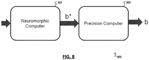
- FIG. 8 shows a simplified block diagram 800 illustrating a dedicated neuromorphic computing device 205 interfacing with a general purpose computing device 805.
- the general purpose computing device 805 may adopt a conventional computer processor architecture and may be used to implement and execute a numerical solver algorithm.
- a SNN prior to running the numerical solver algorithm for a particular matrix inverse problem, a SNN may be programmed and implemented using the neuromorphic computing device 205 that corresponds to matrices involved in the problem to be solved, and the SNN may be run (e.g., by applying an input I corresponding to a vector of the matrix inverse problem) until a steady state is achieved.
- Equilibrium spiking rates of at least a subset of the neurons implemented in the SNN may be observed and an approximate solution to the matrix inverse problem may be derived based on the equilibrium spiking rates (such as in the unclaimed examples of FIGS. 7A-7C discussed above).
- This approximate solution b* may be provided to the general purpose computing device 805 to be used as a first guess or starting point in the high precision numerical solver algorithm (e.g., conjugate gradient, steepest gradient descent, coordinate descent, stochastic gradient descent, etc..
- the approximate solution b* derived using the neuromorphic computer 205 may use the approximate solution b* as an initial guess to seed the same matrix inversion problem modeled by the SNN in the high precision solver algorithm executed by the precision computer 805 to derive a high precision solution b .
- the speed and efficiency of the high precision numerical solver algorithm may be enhanced, allowing a solution to be more quickly determined using the neuromorphic computer 205 and precision computer 805 in tandem, among other examples.
- an SNN implemented using a digital neuromorphic computing device may solve additional regression problems including classes of sparse coding problems that may be utilized in connection with statistics, machine learning, signal processing, and compressive sensing applications, among other examples.
- Equation (9) represent an "Elastic Net" problem, a general form of sparse coding.
- the dictionary matrix may contains the "features" of the data, such as features learned from the data (e.g., by another learning algorithm, such as deep learning algorithm implemented using a different SNN also implemented on the same neuromorphic computing device, among other examples).
- the dictionary matrix is programmed as synaptic weights in the SNN.
- the optimization problem finds a non-negative vector a ⁇ R M that minimizes the loss function L ( a ).
- ⁇ 1 and ⁇ 2 are nonnegative regularization parameters determined by applications.
- matrix inverse problems may present themselves as over-complete inverse problems, where there are a larger number of unknowns (e.g., vector ⁇ 1 ) than equations.
- the dimensions of the I 1 and W discussed in other examples of matrix inverse problems above, may be smaller in dimension than the dimension of ⁇ 1 .
- SNNs generated using a configurable neuromorphic computing device support the addition of negative feedback into the SNN to promote the selection of a sparse solution.
- leakage or a negative bias current e.g., 905
- a configurable neuromorphic computing device configured to implement digital artificial neuron may be configured to establish an SNN.
- SNN a programmer or system may provide SNN definition data defining the connections and parameters of neurons in the SNN. For instance, during configuration, both ⁇ 1 and ⁇ 2 may be defined and given as inputs, together with the dictionary matrix D, input x, and other parameters.
- a two layered SNN may be defined and implemented by a configurable neuromorphic computing device to model and solve Equation (9).
- a first layer of neurons 1005 may be provided to accept the input vector x.
- Feedforward synapses may be provided to connect from each of the first layer neurons 1005 to a second, top layer of recurrently connected neurons 1010.
- the feedforward synapses may be configured with feed-forward weight values corresponding to values of in an instance of Equation (9).
- the synaptic weights of the recurrent synapses connecting the top layer neurons 1010 may be set to correspond to the values of D T D .
- an input vector x may be provided and the SNN may be run until a steady state is observed.
- Spiking rates of the top layer neurons 1010 may be monitored, and the spike rate values observed at steady state may be adopted or interpreted as the solution ⁇ of the problem.
- an SNN configured to solve a sparse code, or Elastic Net, problem may be implemented as a one-layer recurrently connected SNN (similar to the network illustrated in the simplified example in FIG. 4C ).
- an SNN may be configured using the neuromorphic computing device such that a network of N neurons are implemented and interconnected with all-to-all connectivity and up to N 2 synapses.
- the parameters of the SNN e.g., D , ⁇ 1 and ⁇ 2 , x , etc.
- an input may be provided and spiking (or firing) rates of the N neurons may be observed until the network dynamics stabilizes.
- a one-layer implementation of an Elastic Net SNN solver may involve the pre-computation of the vector variable b .
- a neuromorphic computing device may be provided with additional resources to perform these pre-computations.
- such pre-computations may be performed with additional hardware for such arithmetic computations, and the results of these computations may be used in the configuration of an SNN implemented using the neuromorphic computing device, among other example implementations.
- the pre-computation of b may be mitigated by implementing and configuring a three-layer SNN 1100 to solve an Elastic Net or sparse code problem.
- an SNN may be implemented using a neuromorphic computing device that is constructed from 2 M + N neurons, with M neurons 1105 in a sensory layer, N neurons 1110 in an excitatory layer, and M neurons 1115 in an inhibitory layer.
- a total of 3 MN + N synapses may be provided, with M ⁇ N feedforward synapses formed from the sensory layer neurons 1105 to excitatory layer neurons 1110, with the weights denoted as F ⁇ R N ⁇ M .2 ⁇ M ⁇ N synapses may be defined are in both directions between the excitatory layer neurons 1110 and the inhibitory layer neurons 1115, with the weights denoted as P ⁇ R M ⁇ N and Q ⁇ R N ⁇ M , respectively.
- each has an additional synapse connected back to itself, with the weights of these N synapses denoted as a diagonal matrix S ⁇ R N ⁇ N .
- a three layer SNN implementation may reduce the number of synapses from N 2 in the one layer recurrently connected model to 3 MN + N. This reduction may be important in some implementations. For instance, in some cases, a sparse coding problem may be dimensioned such that N ⁇ M , and the resulting N 2 synapses of a one-layer network may be too large a number to implement using a particular neuromorphic computing device's hardware, among other example considerations.
- an input vector x ⁇ R N may be defined and provided to the sensory layer neurons, and the SNN 1100 may be permitted to run until a steady state is reached.
- the sensory layer neurons 1105 may be configured to send out spikes at a constant rate.
- the rate is set the same as the input vector x , e.g., the firing rate of n 1 s is x 1 , the firing rate of n 2 s is x 2 , and so on .
- sensory layer neurons 1105 may be replaced by a spike generator configured to simply inject spikes periodically on synapses towards the excitatory layer neurons 1110 without implementing the sensory layer neurons 1105, among other examples.
- the SNN may be defined such that three dendritic compartments are implemented for the excitatory layer neurons 1110.
- the first compartment, u 1 ( t ) may be defined to contain or correlate with synapses from the sensory layer
- the second compartment, u 2 ( t ) may be defined to contain or correlate synapses from the inhibitory layer
- the third compartment, u 3 ( t ) may be defined to contain or correlate synapses originating from itself.
- the value of c 1 may be advantageously defined such that c 1 > c 2 , c 3 to cause the inhibition to operate at a faster time-scale than feed-forward excitation.
- the values of c 2 and c 3 may be selected such that c 3 > c 2 to cause the self-excitation for compensation to operate at a slower time-scale.
- utilizing multiple dendrites in neurons implemented using a neuromorphic computing device and defining different time-constants (e.g., ⁇ s and ⁇ m ) for each dendrite may help the SNN to converge more smoothly with fewer spikes (and less energy expended).
- Further synaptic weight values may be selected, for instance, between the excitatory and inhibitory layer that are not unique.
- a neuromorphic computing device may be provided with neuromorphic cores capable of implementing digital artificial neurons that may adopt an LIF neuron model.
- the neuromorphic computing device may selectively implement LIF or non-LIF neurons.
- LIF neuron model membrane leakage may be modeled, causing potential collected at the neuron soma to "leak" from the neuron. This membrane leakage may be leveraged to implement the negative bias current of an SNN implemented to solve sparse coding problems.
- the Elastic Net sparse coding problem solved using the example SNNs discussed above may be used, for instance, to determine a feature set for use in a machine learning algorithm.
- feature selection may present itself as an over complete inverse problem capable of being solved as a sparse coding problem.
- the matrix D may correspond to the set of all possible features
- the firing rate of neuron n 1b , n 2b to n N may represent the feature coefficient
- x 1 to x M representing the samples, or input.
- each input vector x may be implemented as a particular digital image vector
- the feature matrix may include features such as the discovery of a diagonal element, a human eye, a circular element, a human nose, sky, water, or other feature depending on the application.
- the features coefficient vector may be found to drive selection and interpretation of the features D .
- the coefficient values ⁇ 1 may correspond to identifying those features that are most important in the sense that they correlate to the input values, with the most important features having the highest coefficients in the model, while features uncorrelated with the output variables having coefficient values close to zero.
- the SNN may be run against a set of inputs in connection with the determination of a corresponding feature-based machine learning model.
- the feature coefficient values may later be used for classification, prediction, or other machine learning purposes.
- a classifier can be trained by taking the data labels and their feature coefficients as input. When a data of unknown class is presented, the classifier can use its feature coefficients to classify.
- the classifier may be implemented on the neuromorphic computing device, or on another general purpose computer.
- sparse coding may include signal processing and compressive sensing.
- signal processing one can obtain the feature coefficients by solving the sparse coding problems, and use the feature coefficients to reconstruct the original signal using the dictionary matrix.
- Such reconstruction typically can reduce the noise presented in the given signal, and enhance its signal-to-noise ratio.
- the reconstruction may also recover missing or corrupted information in the given signal.
- compressive sensing one need to decompress the compressed measurements in order to obtain the desired measured signal. The decompression process can be realized by solving the sparse coding problem, where the dictionary matrix is replaced by the measurement matrix, and the signal reconstruction is obtained using the solved feature coefficients, among other examples
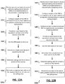
- FIGS. 12A-12C are flowcharts 1200a-c illustrating unclaimed example techniques involving solving matrix inverse problems utilizing spiking neural networks.
- one or more inputs are received 1205 at a neuromorphic computing device to cause a particular spiking neural network (SNN) to be defined and implemented using neuromorphic cores of the neuromorphic computing device according to the definition.
- the SNN may include multiple artificial neurons connected by a plurality of artificial synapses.
- Weight values may be configured 1210 for each of the synapses. The assignment of weight values to respective individual synapses may be made to correlate to values in one or more matrices to be operated upon within the equation.
- parameters of the SNN may also be set to implement the particular SNN, such as neurons' firing thresholds, synaptic decay time constants, and membrane decay time constant, among other examples.
- the synapses in some cases may be used to recurrently connect at least a portion of the synapses to correspond to the inversion of at least one of the one or more matrices.
- An input may be provided 1215 to the SNN, the input having values corresponding to a vector to be multiplied against one or more of the matrices in the equation.
- the SNN may be run 1220 based on the input until a steady state of the SNN is determined 1225 (e.g., from monitoring of spiking firing rates within the SNN (e.g., which may be determined by monitoring traffic on routers of the neuromorphic computing device implementing the SNN)).
- Spiking rates may converge for at least a particular portion of the neurons in the SNN at steady state, and these spiking rates may be determined 1230 and an approximate solution to the equation may be determined 1235 from the values of the spiking rates determined 1230 for the particular portion of neurons.
- an outside process may be used to monitor traffic in the neuromorphic computing device to determine 1225 a steady state, determine 1230 spiking rates, and/or determine 1235 the approximate solution state.
- such logic may be provided and programmed to be executed locally on the neuromorphic computing device, among other example implementations.
- one or more inputs are received 1240 at a neuromorphic computing device to cause a particular spiking neural network (SNN) to be defined and implemented using neuromorphic cores of the neuromorphic computing device according to the definition.
- the SNN may include multiple artificial neurons connected by a plurality of artificial synapses. Weight values may be configured 1245 for each of the synapses. The assignment 1245 of weight values to respective individual synapses may be made to correlate to values in one or more matrices to be operated upon within the equation. At least a portion of the neurons in the SNN may be configured 1250 with attributes to negatively bias or impede the accumulation of spiking potential at the corresponding neuron.
- This may be used to encourage the SNN to behave in a manor to solve a sparse coding problem (e.g., to generate a sparse solution to an over complete problem represented by the equation).
- An input may be provided 1255 to the configured SNN and the SNN may be run 1260 based on the input until a steady state is determined 1265 to be reached in the SNN.
- Spiking rates of a particular portion of the SNN e.g., all the neurons or a particular subset of neurons
- may be determined 1270. These determined 1270 spiking rates may be utilized to determine 1275 a solution to the sparse coding problem.
- a neuromorphic computing device may include a network of neuromorphic processing cores (e.g., each with a respective arithmetic processing unit and local memory) that may each be used to implement one or more artificial neurons and define synapses between the artificial neurons to construct an SNN.
- a single core of the neuromorphic computing device may implement multiple neurons within the SNN and may time multiplex access to the core's resources (e.g., processor resources) by the processes (e.g., dendritic and somatic modeling processes) used to implement each of the multiple neurons.
- Time steps may be defined and utilized with the neuromorphic computing device to synchronize the varied processes of the multiple core implementing the various neurons with an example SNN.
- a neuromorphic core may provide for the neurons to send spikes that are to be sent (e.g., based on previously received presynaptic spikes).
- a time synchronization barrier process may be utilized by the neuromorphic computing device to guarantee that all spikes scheduled in the previous time step have been delivered before moving to the next time step. Spikes may arrive at neurons in the SNN in arbitrary sequential order, and cause subsequent dendrite and soma process at the receiving neurons (e.g., all in the same time step).
- a first one of multiple neurons concurrently implemented by the core may first send any spikes it is to send.
- Inputs e.g., provided to the neuron as part of an input vector or as a spike message from another connected neuron
- Inputs may then be received 1280 and processed.
- the core can continue dividing the time step and time multiplexing its processing resources until all of the neurons it implements in the SNN have been processed to identify any received presynaptic spikes and determine any resulting postsynaptic spikes.
- the next time step may begin with the firing of spikes determined in the preceding time step, followed by the processing of spikes and determination of additional spikes (e.g., steps 1280, 1282, 1284, 1286,
- Spiking rate values for a particular set of neurons within the SNN may be determined 1294 and a solution to an equation modeled by the SNN may be determined 1296 from the spike rate identified in the steady state.
- FIGS. 13-14 are block diagrams of exemplary computer architectures that may be used in accordance with embodiments disclosed herein. Other computer architecture designs known in the art for processors and computing systems may also be used. Generally, suitable computer architectures for embodiments disclosed herein can include, but are not limited to, configurations illustrated in FIGS. 13-14 .
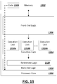
- FIG. 13 is an example illustration of a processor according to an unclaimed embodiment.
- Processor 1300 is an example of a type of hardware device that can be used in connection with the implementations above.
- Processor 1300 may be any type of processor, such as a microprocessor, an embedded processor, a digital signal processor (DSP), a network processor, a multi-core processor, a single core processor, or other device to execute code.
- DSP digital signal processor
- a processing element may alternatively include more than one of processor 1300 illustrated in FIG. 13 .
- Processor 1300 may be a single-threaded core or, for at least one embodiment, the processor 1300 may be multi-threaded in that it may include more than one hardware thread context (or "logical processor") per core.
- FIG. 13 also illustrates a memory 1302 coupled to processor 1300 in accordance with an embodiment.
- Memory 1302 may be any of a wide variety of memories (including various layers of memory hierarchy) as are known or otherwise available to those of skill in the art.
- Such memory elements can include, but are not limited to, random access memory (RAM), read only memory (ROM), logic blocks of a field programmable gate array (FPGA), erasable programmable read only memory (EPROM), and electrically erasable programmable ROM (EEPROM).
- RAM random access memory
- ROM read only memory
- FPGA field programmable gate array
- EPROM erasable programmable read only memory
- EEPROM electrically erasable programmable ROM
- Processor 1300 can execute any type of instructions associated with algorithms, processes, or operations detailed herein. Generally, processor 1300 can transform an element or an article (e.g., data) from one state or thing to another state or thing.
- processor 1300 can transform an element or an article (e.g., data) from one state or thing to another state or thing.
- Code 1304 which may be one or more instructions to be executed by processor 1300, may be stored in memory 1302, or may be stored in software, hardware, firmware, or any suitable combination thereof, or in any other internal or external component, device, element, or object where appropriate and based on particular needs.
- processor 1300 can follow a program sequence of instructions indicated by code 1304.
- Each instruction enters a front-end logic 1306 and is processed by one or more decoders 1308.
- the decoder may generate, as its output, a micro operation such as a fixed width micro operation in a predefined format, or may generate other instructions, microinstructions, or control signals that reflect the original code instruction.
- Front-end logic 1306 also includes register renaming logic 1310 and scheduling logic 1312, which generally allocate resources and queue the operation corresponding to the instruction for execution.
- Processor 1300 can also include execution logic 1314 having a set of execution units 1316a, 1316b, 1316n, etc. Some unclaimed embodiments may include a number of execution units dedicated to specific functions or sets of functions. Other unclaimed embodiments may include only one execution unit or one execution unit that can perform a particular function. Execution logic 1314 performs the operations specified by code instructions.
- back-end logic 1318 can retire the instructions of code 1304.
- processor 1300 allows out of order execution but requires in order retirement of instructions.
- Retirement logic 1320 may take a variety of known forms (e.g., re-order buffers or the like). In this manner, processor 1300 is transformed during execution of code 1304, at least in terms of the output generated by the decoder, hardware registers and tables utilized by register renaming logic 1310, and any registers (not shown) modified by execution logic 1314.
- a processing element may include other elements on a chip with processor 1300.
- a processing element may include memory control logic along with processor 1300.
- the processing element may include I/O control logic and/or may include I/O control logic integrated with memory control logic.
- the processing element may also include one or more caches.
- nonvolatile memory such as flash memory or fuses may also be included on the chip with processor 1300.
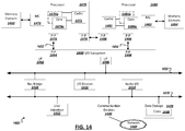
- FIG. 14 illustrates a computing system 1400 that is arranged in a point-to-point (PtP) configuration according to an unclaimed embodiment.
- FIG. 14 shows a system where processors, memory, and input/output devices are interconnected by a number of point-to-point interfaces.
- processors, memory, and input/output devices are interconnected by a number of point-to-point interfaces.
- one or more of the computing systems described herein may be configured in the same or similar manner as computing system 1400.
- Processors 1470 and 1480 may also each include integrated memory controller logic (MC) 1472 and 1482 to communicate with memory elements 1432 and 1434.
- MC memory controller logic
- memory controller logic 1472 and 1482 may be discrete logic separate from processors 1470 and 1480.
- Memory elements 1432 and/or 1434 may store various data to be used by processors 1470 and 1480 in achieving operations and functionality outlined herein.
- Processors 1470 and 1480 may be any type of processor, such as those discussed in connection with other figures.
- Processors 1470 and 1480 may exchange data via a point-to-point (PtP) interface 1450 using point-to-point interface circuits 1478 and 1488, respectively.
- Processors 1470 and 1480 may each exchange data with a chipset 1490 via individual point-to-point interfaces 1452 and 1454 using point-to-point interface circuits 1476, 1486, 1494, and 1498.
- Chipset 1490 may also exchange data with a high-performance graphics circuit 1438 via a high-performance graphics interface 1439, using an interface circuit 1492, which could be a PtP interface circuit.
- any or all of the PtP links illustrated in FIG. 14 could be implemented as a multi-drop bus rather than a PtP link.
- Chipset 1490 may be in communication with a bus 1420 via an interface circuit 1496.
- Bus 1420 may have one or more devices that communicate over it, such as a bus bridge 1418 and I/O devices 1416.
- bus bridge 1418 may be in communication with other devices such as a user interface 1412 (such as a keyboard, mouse, touchscreen, or other input devices), communication devices 1426 (such as modems, network interface devices, or other types of communication devices that may communicate through a computer network 1460), audio I/O devices 1414, and/or a data storage device 1428.
- Data storage device 1428 may store code 1430, which may be executed by processors 1470 and/or 1480.
- any portions of the bus architectures could be implemented with one or more PtP links.
- the computer system depicted in FIG. 14 is a schematic illustration of an embodiment of a computing system that may be utilized to implement various unclaimed embodiments discussed herein. It will be appreciated that various components of the system depicted in FIG. 14 may be combined in a system-on-a-chip (SoC) architecture or in any other suitable configuration capable of achieving the functionality and features of examples and implementations provided herein.
- SoC system-on-a-chip
Landscapes
- Engineering & Computer Science (AREA)
- Physics & Mathematics (AREA)
- Theoretical Computer Science (AREA)
- Health & Medical Sciences (AREA)
- Life Sciences & Earth Sciences (AREA)
- Biomedical Technology (AREA)
- Biophysics (AREA)
- General Health & Medical Sciences (AREA)
- Data Mining & Analysis (AREA)
- Evolutionary Computation (AREA)
- Computational Linguistics (AREA)
- Molecular Biology (AREA)
- Computing Systems (AREA)
- General Engineering & Computer Science (AREA)
- General Physics & Mathematics (AREA)
- Mathematical Physics (AREA)
- Software Systems (AREA)
- Artificial Intelligence (AREA)
- Neurology (AREA)
- Image Analysis (AREA)
Claims (5)
- Computerimplementiertes Verfahren, umfassend:Erzeugen einer Vielzahl von künstlichen Neuronen, wobei mindestens ein erster Teil der Vielzahl von Neuronen Attribute umfasst, um die Akkumulation von Potential an dem jeweiligen Neuron zu hemmen, das auf Spike-Nachrichten reagiert, die an dem Neuron empfangen werden sollen;Definieren, unter Verwendung einer oder mehrerer Routing-Tabellen, eines gepulsten neuronalen Netzwerks, das die Vielzahl von künstlichen Neuronen umfasst, die durch eine Vielzahl von künstlichen Synapsen miteinander verbunden sind, wobei das gepulste neuronale Netzwerk definiert ist,um einer numerischen Matrix zu entsprechen, wobei jede der Vielzahl von künstlichen Synapsen einen jeweilige Gewichtungswert umfasst und die Gewichtungswerte von mindestens einem ersten Teil der Vielzahl künstlicher Synapsen auf Werten in der numerischen Matrix basieren sollen;Bereitstellen, für das gepulste neuronale Netzwerk, einer Vielzahl von Eingaben, wobei die Vielzahl von Eingaben ausgewählt werden, um einem numerischen Vektor zu entsprechen;Bestimmen einer stationären Spiking-Rate für mindestens einen zweiten Teil der Vielzahl von künstlichen Neuronen basierend auf der Vielzahl von Eingaben; undBestimmen eines Sparse-Basisvektors basierend auf den stationären Spiking-Ratenwerten, die für mindestens den zweiten Teil der Vielzahl von künstlichen Neuronen bestimmt wurden,dadurch gekennzeichnet, dassdas Erzeugen der Vielzahl von Neuronen das Einstellen von Parametern für jedes der Vielzahl von Neuronen umfasst,wobei die Parameter eine oder mehrere von einer Feuerschwelle, einer synaptischen Abklingzeitkonstante,einer Membranpotential-Abklingzeitkonstante und einem Vorspannungsstrom umfassen,das gepulste neuronale Netzwerk die Vielzahl von Neuronen in drei Schichten verbindet, die Neuronen in einer ersten der drei Schichten über Feedforward-Verbindungen unter Verwendung von einer ersten Teilmenge der Vielzahl von Synapsen mit Neuronen in einer zweiten der drei Schichten verbunden werden sollen, die Neuronen in der zweiten Schicht über Feedforward-Verbindungen unter Verwendung einer zweiten Teilmenge der Vielzahl von Synapsen mit Neuronen in einer dritten der drei Schichten verbunden werden sollen, die Neuronen in der dritten Schicht über Rückkopplungsverbindungen unter Verwendung einer dritten Teilmenge der Vielzahl von Synapsen mit Neuronen in der zweiten Schicht verbunden werden sollen und jedes der Neuronen in der zweiten Schicht durch Synapsen in einer vierten Teilmenge der Vielzahl von Synapsen mit sich selbst verbunden werden soll,der Vorspannungsstrom jedes der Neuronen in der zweiten Schicht auf einen ersten nicht negativen Regularisierungsparameter λ1 eingestellt werden soll, die Feuerschwelle auf einen Wert von 2λ2+1 eingestellt werden soll, wobei λ2 einen zweiten nicht negativen Regularisierungsparameter umfasst, und die Membranpotential-Abklingzeitkonstante größer als die synaptische Abklingzeitkonstante eingestellt werden soll,das gepulste neuronale Netzwerk unter Verwendung einer neuromorphen Computervorrichtung implementiert wird, die ein Netzwerk von neuromorphen Kernen umfasst, unddas Netzwerk von neuromorphen Kernen umfasst:eine Vielzahl von neuromorphen Kernen, wobei jeder neuromorphe Kern der Vielzahl von neuromorphen Kernen eine jeweilige Verarbeitungsressource und Logik zum Implementieren eines oder mehrerer künstlicher Neuronen umfasst; undeinen oder mehrere Router zum Weiterleiten von Spiking-Nachrichten zwischen künstlichen Neuronen, die unter Verwendung der Vielzahl von neuromorphen Kernen implementiert sind; und einen Speicher, der Daten umfasst, um Verbindungen der Vielzahl von künstlichen Neuronen in dem gepulsten neuronalen Netzwerk zu definieren.
- Verfahren nach Anspruch 1, wobei jedes der Neuronen in der zweiten Schicht drei dendritische Kompartimente umfasst, wobei ein erstes der dendritischen Kompartimente den Synapsen in der ersten Teilmenge von Synapsen entspricht, ein zweites der dendritischen Kompartimente den Synapsen in der zweiten Teilmenge der Synapsen entspricht und ein drittes der dendritischen Kompartimente den Synapsen in der vierten Teilmenge der Synapsen entspricht.
- Verfahren nach Anspruch 1 oder 2, wobei jeder neuromorphe Kern zwei oder mehr der Vielzahl von künstlichen Neuronen implementieren soll.
- Verfahren nach Anspruch 3, wobei die neuromorphen Kerne den Zugriff auf die Verarbeitungsressourcen des jeweiligen neuromorphen Kerns zeitlich multiplexieren, um die zwei oder mehr künstlichen Neuronen gleichzeitig zu implementieren.
- Vorrichtung, umfassend:eine neuromorphe Computervorrichtung, umfassend:einen oder mehrere Router;eine Vielzahl von neuromorphen Kernen, die durch den einen oder die mehreren Router miteinander verbunden sind, wobei jeder neuromorphe Kern der Vielzahl umfasst:einen Prozessor;einen Speicher, um eine oder mehrere Routing-Tabellen zu speichern; undeine Logik, um eine Vielzahl von künstlichen Neuronen zu implementieren, die von dem neuromorphen Kern gehostet werden sollen,wobei der eine oder die mehreren Router die Spiking-Nachrichten zwischen der Vielzahl von künstlichen Neuronen weiterleiten sollen und die eine oder die mehreren Routing-Tabellen Synapsen definieren, um die künstlichen Neuronen miteinander zu verbinden, um ein gepulstes neuronales Netzwerk zu definieren, das die künstlichen Neuronen umfasst, das gepulste neuronale Netzwerk definiert ist, um einer numerischen Matrix zu entsprechen, jede der Vielzahl von künstlichen Synapsen einen jeweiligen Gewichtungswert besitzt, und die Gewichtungswerte von mindestens einem ersten Teil der Vielzahl von künstlichen Synapsen auf Werten in der numerischen Matrix basieren sollen; undeine Logik, um:einen Eingabevektor für das gepulste neuronale Netzwerk bereitzustellen; undaus einem stationären Zustand des gepulsten neuronalen Netzwerks die Spiking-Raten eines bestimmten Teils der künstlichen Neuronen zu bestimmen, um eine Lösung für ein Problem aufgrund Sparse-Kodierung darzustellen, die der numerischen Matrix entspricht, dadurch gekennzeichnet, dassjedes der künstlichen Neuronen einen jeweiligen Dendritenprozess und einen jeweiligen individuellen Somaprozess umfasst, der unter Verwendung des Prozessors ausgeführt werden soll,die Logik dazu dient, Parameter für jedes des einen oder der mehreren künstlichen Neuronen einzustellen, wobei die Parameter eine oder mehrere von einer Feuerschwelle, einer synaptischen Abklingzeitkonstante, einer Membranpotential-Abklingzeitkonstante und einem Vorspannungsstrom umfassen,das gepulste neuronale Netzwerk die Vielzahl von künstlichen Neuronen in drei Schichten verbindet, die künstlichen Neuronen in einer ersten der drei Schichten über Feedforward-Verbindungen unter Verwendung von einer ersten Teilmenge der Vielzahl von künstlichen Synapsen mit künstlichen Neuronen in einer zweiten der drei Schichten verbunden werden sollen, die künstlichen Neuronen in der zweiten Schicht über Feedforward-Verbindungen unter Verwendung einer zweiten Teilmenge der Vielzahl von künstlichen Synapsen mit künstlichen Neuronen in einer dritten der drei Schichten verbunden werden sollen, die künstlichen Neuronen in der dritten Schicht über Rückkopplungsverbindungen unter Verwendung einer dritten Teilmenge der Vielzahl von künstlichen Synapsen mit künstlichen Neuronen in der zweiten Schicht verbunden werden sollen und jedes der künstlichen Neuronen in der zweiten Schicht durch künstlichen Synapsen in einer vierten Teilmenge der Vielzahl von künstlichen Synapsen mit sich selbst verbunden werden soll,der Vorspannungsstrom jedes der künstlichen Neuronen in der zweiten Schicht auf einen ersten nicht negativen Regularisierungsparameter λ1 eingestellt werden soll, die Feuerschwelle auf einen Wert von 2λ2+1 eingestellt werden soll, wobei λ2 einen zweiten nicht negativen Regularisierungsparameter umfasst, und die Membranpotential-Abklingzeitkonstante größer als die synaptische Abklingzeitkonstante eingestellt werden soll.
Applications Claiming Priority (1)
| Application Number | Priority Date | Filing Date | Title |
|---|---|---|---|
| US15/385,541 US20180174028A1 (en) | 2016-12-20 | 2016-12-20 | Sparse coding using neuromorphic computing |
Publications (2)
| Publication Number | Publication Date |
|---|---|
| EP3340124A1 EP3340124A1 (de) | 2018-06-27 |
| EP3340124B1 true EP3340124B1 (de) | 2021-05-05 |
Family
ID=60582482
Family Applications (1)
| Application Number | Title | Priority Date | Filing Date |
|---|---|---|---|
| EP17205542.8A Active EP3340124B1 (de) | 2016-12-20 | 2017-12-05 | Sparse-coding mittels neuromorpher berechnung |
Country Status (2)
| Country | Link |
|---|---|
| US (1) | US20180174028A1 (de) |
| EP (1) | EP3340124B1 (de) |
Families Citing this family (22)
| Publication number | Priority date | Publication date | Assignee | Title |
|---|---|---|---|---|
| JP6863089B2 (ja) * | 2017-05-30 | 2021-04-21 | トヨタ自動車株式会社 | 変数群演算装置、変数群演算方法、及び変数群演算プログラム |
| US11195079B2 (en) * | 2017-11-22 | 2021-12-07 | Intel Corporation | Reconfigurable neuro-synaptic cores for spiking neural network |
| US11645501B2 (en) * | 2018-02-28 | 2023-05-09 | International Business Machines Corporation | Distributed, event-based computation using neuromorphic cores |
| WO2020260422A1 (en) * | 2019-06-24 | 2020-12-30 | Aictx Ag | An event-driven spiking neutral network system for detection of physiological conditions |
| CN110543933B (zh) * | 2019-08-12 | 2022-10-21 | 北京大学 | 基于flash存算阵列的脉冲型卷积神经网络 |
| US11727252B2 (en) | 2019-08-30 | 2023-08-15 | International Business Machines Corporation | Adaptive neuromorphic neuron apparatus for artificial neural networks |
| US11915124B2 (en) * | 2019-09-05 | 2024-02-27 | Micron Technology, Inc. | Performing processing-in-memory operations related to spiking events, and related methods, systems and devices |
| KR102925654B1 (ko) | 2019-09-05 | 2026-02-11 | 마이크론 테크놀로지, 인크 | 시냅스-전 스파이크 신호에 관련된 메모리 내 프로세싱 동작 수행 및 관련 방법, 시스템 |
| CN113222103B (zh) * | 2020-02-05 | 2025-12-19 | 北京三星通信技术研究有限公司 | 神经网络的更新方法、分类方法和电子设备 |
| US12393841B2 (en) | 2020-02-05 | 2025-08-19 | Samsung Electronics Co., Ltd. | Neural network update method, classification method and electronic device |
| US11379558B2 (en) * | 2020-05-12 | 2022-07-05 | National Cheng Kung University | System enhancement methodology via matrix multiplication efficiency speedup using sparse basis approach |
| US11500644B2 (en) | 2020-05-15 | 2022-11-15 | Alibaba Group Holding Limited | Custom instruction implemented finite state machine engines for extensible processors |
| US11481214B2 (en) | 2020-07-14 | 2022-10-25 | Alibaba Group Holding Limited | Sparse matrix calculations untilizing ightly tightly coupled memory and gather/scatter engine |
| US12682224B2 (en) | 2020-11-18 | 2026-07-14 | Micron Technology, Inc. | Routing spike messages in spiking neural networks |
| CN112906828A (zh) * | 2021-04-08 | 2021-06-04 | 周士博 | 一种基于时域编码和脉冲神经网络的图像分类方法 |
| US12314845B2 (en) * | 2021-10-14 | 2025-05-27 | Tata Consultancy Services Limited | Field programmable gate array (FPGA) based neuromorphic computing architecture |
| CN114372568B (zh) * | 2022-03-21 | 2022-07-15 | 深圳时识科技有限公司 | 类脑芯片及电子设备 |
| CN116224947B (zh) * | 2023-04-10 | 2023-11-14 | 济南永信新材料科技有限公司 | 可主动融入领域规则知识的深度学习工业控制系统 |
| CN116700727B (zh) * | 2023-06-21 | 2024-02-13 | 广州洋葱时尚集团有限公司 | 一种跨平台的数据处理方法及系统 |
| US20250013860A1 (en) * | 2023-07-06 | 2025-01-09 | National Technology & Engineering Solutions Of Sandia, Llc | Neural circuits for learning solutions for discrete optimization |
| US20250123802A1 (en) * | 2023-10-11 | 2025-04-17 | Taalas Inc. | Large Parameter Set Computation Accelerator Using Configurable Connectivity Mesh |
| CN118982057B (zh) * | 2024-06-24 | 2026-08-11 | 北京大学 | 一种snn加速器及snn突触权重混合压缩存储方法 |
-
2016
- 2016-12-20 US US15/385,541 patent/US20180174028A1/en not_active Abandoned
-
2017
- 2017-12-05 EP EP17205542.8A patent/EP3340124B1/de active Active
Non-Patent Citations (1)
| Title |
|---|
| JAVIER NAVARIDAS ET AL: "SpiNNaker: Enhanced multicast routing", PARALLEL COMPUTING, vol. 45, 1 June 2015 (2015-06-01), AMSTERDAM, NL, pages 49 - 66, XP055619566, ISSN: 0167-8191, DOI: 10.1016/j.parco.2015.01.002 * |
Also Published As
| Publication number | Publication date |
|---|---|
| EP3340124A1 (de) | 2018-06-27 |
| US20180174028A1 (en) | 2018-06-21 |
Similar Documents
| Publication | Publication Date | Title |
|---|---|---|
| EP3340117B1 (de) | Unbeaufsichtigtes lernen mithilfe von neuromorpher berechnung | |
| EP3340124A1 (de) | Sparse-coding mittels neuromorpher berechnung | |
| US10679118B2 (en) | Solving matrix inverse problems using neuromorphic computing | |
| US11481621B2 (en) | Unsupervised, supervised and reinforced learning via spiking computation | |
| US10878313B2 (en) | Post synaptic potential-based learning rule | |
| US10891544B2 (en) | Event-driven universal neural network circuit | |
| Gelenbe et al. | Deep learning with random neural networks | |
| KR102896234B1 (ko) | 인식 방법 및 인식 장치 | |
| US9460387B2 (en) | Apparatus and methods for implementing event-based updates in neuron networks | |
| Davies et al. | A forecast-based STDP rule suitable for neuromorphic implementation | |
| Pande | Design Exploration of EMBRACE Hardware Spiking Neural Network Architecture and Applications | |
| Shahsavari et al. | POETS: A parallel cluster architecture for Spiking Neural Network | |
| Engelken | Chaotic neural circuit dynamics | |
| Liu et al. | Knowledge distillation between DNN and SNN for intelligent sensing systems on loihi chip | |
| Chaudron et al. | Evaluation of Gated Recurrent Neural Networks for Embedded Systems Applications | |
| De Ladurantaye et al. | A parallel supercomputer implementation of a biological inspired neural network and its use for pattern recognition | |
| Tomás | Neuromorphic Neural Networks | |
| Jean-Baptiste Chaudron et al. | for Embedded Systems Applications | |
| Mena-Morales et al. | Brainsat: Hardware development of a neuromorphic on-board computer applied to methane detection from low earth orbit Raphael Mena-Morales1, Pablo Miralles1, Michael Skreta1, Diviya Devani1, George Metaxas1, Eric Knappenberger1, Prerna Baranwal2 | |
| КОSOVETS et al. | and COMPUTER TECHNOLOGIES | |
| Yin | Sparse Learning in Brain Networks and Brain-like Artificial Intelligence | |
| OJIUGWO | Spiking Neural Network Architecture Design and Performance Exploration towards the Design of a Scalable Neuro-Inspired System for Complex Cognition Applications | |
| Mohamad | Distributed Learning for Back Propagation in Character Recognition |
Legal Events
| Date | Code | Title | Description |
|---|---|---|---|
| PUAI | Public reference made under article 153(3) epc to a published international application that has entered the european phase |
Free format text: ORIGINAL CODE: 0009012 |
|
| STAA | Information on the status of an ep patent application or granted ep patent |
Free format text: STATUS: REQUEST FOR EXAMINATION WAS MADE |
|
| 17P | Request for examination filed |
Effective date: 20171205 |
|
| AK | Designated contracting states |
Kind code of ref document: A1 Designated state(s): AL AT BE BG CH CY CZ DE DK EE ES FI FR GB GR HR HU IE IS IT LI LT LU LV MC MK MT NL NO PL PT RO RS SE SI SK SM TR |
|
| AX | Request for extension of the european patent |
Extension state: BA ME |
|
| STAA | Information on the status of an ep patent application or granted ep patent |
Free format text: STATUS: EXAMINATION IS IN PROGRESS |
|
| 17Q | First examination report despatched |
Effective date: 20190917 |
|
| GRAP | Despatch of communication of intention to grant a patent |
Free format text: ORIGINAL CODE: EPIDOSNIGR1 |
|
| STAA | Information on the status of an ep patent application or granted ep patent |
Free format text: STATUS: GRANT OF PATENT IS INTENDED |
|
| INTG | Intention to grant announced |
Effective date: 20201202 |
|
| GRAS | Grant fee paid |
Free format text: ORIGINAL CODE: EPIDOSNIGR3 |
|
| GRAA | (expected) grant |
Free format text: ORIGINAL CODE: 0009210 |
|
| STAA | Information on the status of an ep patent application or granted ep patent |
Free format text: STATUS: THE PATENT HAS BEEN GRANTED |
|
| AK | Designated contracting states |
Kind code of ref document: B1 Designated state(s): AL AT BE BG CH CY CZ DE DK EE ES FI FR GB GR HR HU IE IS IT LI LT LU LV MC MK MT NL NO PL PT RO RS SE SI SK SM TR |
|
| REG | Reference to a national code |
Ref country code: GB Ref legal event code: FG4D |
|
| REG | Reference to a national code |
Ref country code: CH Ref legal event code: EP |
|
| REG | Reference to a national code |
Ref country code: AT Ref legal event code: REF Ref document number: 1390736 Country of ref document: AT Kind code of ref document: T Effective date: 20210515 |
|
| REG | Reference to a national code |
Ref country code: IE Ref legal event code: FG4D |
|
| REG | Reference to a national code |
Ref country code: DE Ref legal event code: R096 Ref document number: 602017037984 Country of ref document: DE |
|
| REG | Reference to a national code |
Ref country code: NL Ref legal event code: FP |
|
| REG | Reference to a national code |
Ref country code: LT Ref legal event code: MG9D |
|
| REG | Reference to a national code |
Ref country code: AT Ref legal event code: MK05 Ref document number: 1390736 Country of ref document: AT Kind code of ref document: T Effective date: 20210505 |
|
| PG25 | Lapsed in a contracting state [announced via postgrant information from national office to epo] |
Ref country code: HR Free format text: LAPSE BECAUSE OF FAILURE TO SUBMIT A TRANSLATION OF THE DESCRIPTION OR TO PAY THE FEE WITHIN THE PRESCRIBED TIME-LIMIT Effective date: 20210505 Ref country code: AT Free format text: LAPSE BECAUSE OF FAILURE TO SUBMIT A TRANSLATION OF THE DESCRIPTION OR TO PAY THE FEE WITHIN THE PRESCRIBED TIME-LIMIT Effective date: 20210505 Ref country code: BG Free format text: LAPSE BECAUSE OF FAILURE TO SUBMIT A TRANSLATION OF THE DESCRIPTION OR TO PAY THE FEE WITHIN THE PRESCRIBED TIME-LIMIT Effective date: 20210805 Ref country code: FI Free format text: LAPSE BECAUSE OF FAILURE TO SUBMIT A TRANSLATION OF THE DESCRIPTION OR TO PAY THE FEE WITHIN THE PRESCRIBED TIME-LIMIT Effective date: 20210505 Ref country code: LT Free format text: LAPSE BECAUSE OF FAILURE TO SUBMIT A TRANSLATION OF THE DESCRIPTION OR TO PAY THE FEE WITHIN THE PRESCRIBED TIME-LIMIT Effective date: 20210505 |
|
| PG25 | Lapsed in a contracting state [announced via postgrant information from national office to epo] |
Ref country code: LV Free format text: LAPSE BECAUSE OF FAILURE TO SUBMIT A TRANSLATION OF THE DESCRIPTION OR TO PAY THE FEE WITHIN THE PRESCRIBED TIME-LIMIT Effective date: 20210505 Ref country code: IS Free format text: LAPSE BECAUSE OF FAILURE TO SUBMIT A TRANSLATION OF THE DESCRIPTION OR TO PAY THE FEE WITHIN THE PRESCRIBED TIME-LIMIT Effective date: 20210905 Ref country code: GR Free format text: LAPSE BECAUSE OF FAILURE TO SUBMIT A TRANSLATION OF THE DESCRIPTION OR TO PAY THE FEE WITHIN THE PRESCRIBED TIME-LIMIT Effective date: 20210806 Ref country code: RS Free format text: LAPSE BECAUSE OF FAILURE TO SUBMIT A TRANSLATION OF THE DESCRIPTION OR TO PAY THE FEE WITHIN THE PRESCRIBED TIME-LIMIT Effective date: 20210505 Ref country code: SE Free format text: LAPSE BECAUSE OF FAILURE TO SUBMIT A TRANSLATION OF THE DESCRIPTION OR TO PAY THE FEE WITHIN THE PRESCRIBED TIME-LIMIT Effective date: 20210505 Ref country code: PT Free format text: LAPSE BECAUSE OF FAILURE TO SUBMIT A TRANSLATION OF THE DESCRIPTION OR TO PAY THE FEE WITHIN THE PRESCRIBED TIME-LIMIT Effective date: 20210906 Ref country code: NO Free format text: LAPSE BECAUSE OF FAILURE TO SUBMIT A TRANSLATION OF THE DESCRIPTION OR TO PAY THE FEE WITHIN THE PRESCRIBED TIME-LIMIT Effective date: 20210805 Ref country code: PL Free format text: LAPSE BECAUSE OF FAILURE TO SUBMIT A TRANSLATION OF THE DESCRIPTION OR TO PAY THE FEE WITHIN THE PRESCRIBED TIME-LIMIT Effective date: 20210505 |
|
| PG25 | Lapsed in a contracting state [announced via postgrant information from national office to epo] |
Ref country code: SK Free format text: LAPSE BECAUSE OF FAILURE TO SUBMIT A TRANSLATION OF THE DESCRIPTION OR TO PAY THE FEE WITHIN THE PRESCRIBED TIME-LIMIT Effective date: 20210505 Ref country code: SM Free format text: LAPSE BECAUSE OF FAILURE TO SUBMIT A TRANSLATION OF THE DESCRIPTION OR TO PAY THE FEE WITHIN THE PRESCRIBED TIME-LIMIT Effective date: 20210505 Ref country code: DK Free format text: LAPSE BECAUSE OF FAILURE TO SUBMIT A TRANSLATION OF THE DESCRIPTION OR TO PAY THE FEE WITHIN THE PRESCRIBED TIME-LIMIT Effective date: 20210505 Ref country code: CZ Free format text: LAPSE BECAUSE OF FAILURE TO SUBMIT A TRANSLATION OF THE DESCRIPTION OR TO PAY THE FEE WITHIN THE PRESCRIBED TIME-LIMIT Effective date: 20210505 Ref country code: EE Free format text: LAPSE BECAUSE OF FAILURE TO SUBMIT A TRANSLATION OF THE DESCRIPTION OR TO PAY THE FEE WITHIN THE PRESCRIBED TIME-LIMIT Effective date: 20210505 Ref country code: RO Free format text: LAPSE BECAUSE OF FAILURE TO SUBMIT A TRANSLATION OF THE DESCRIPTION OR TO PAY THE FEE WITHIN THE PRESCRIBED TIME-LIMIT Effective date: 20210505 Ref country code: ES Free format text: LAPSE BECAUSE OF FAILURE TO SUBMIT A TRANSLATION OF THE DESCRIPTION OR TO PAY THE FEE WITHIN THE PRESCRIBED TIME-LIMIT Effective date: 20210505 |
|
| REG | Reference to a national code |
Ref country code: DE Ref legal event code: R097 Ref document number: 602017037984 Country of ref document: DE |
|
| PLBE | No opposition filed within time limit |
Free format text: ORIGINAL CODE: 0009261 |
|
| STAA | Information on the status of an ep patent application or granted ep patent |
Free format text: STATUS: NO OPPOSITION FILED WITHIN TIME LIMIT |
|
| 26N | No opposition filed |
Effective date: 20220208 |
|
| PG25 | Lapsed in a contracting state [announced via postgrant information from national office to epo] |
Ref country code: IS Free format text: LAPSE BECAUSE OF FAILURE TO SUBMIT A TRANSLATION OF THE DESCRIPTION OR TO PAY THE FEE WITHIN THE PRESCRIBED TIME-LIMIT Effective date: 20210905 Ref country code: AL Free format text: LAPSE BECAUSE OF FAILURE TO SUBMIT A TRANSLATION OF THE DESCRIPTION OR TO PAY THE FEE WITHIN THE PRESCRIBED TIME-LIMIT Effective date: 20210505 |
|
| PG25 | Lapsed in a contracting state [announced via postgrant information from national office to epo] |
Ref country code: MC Free format text: LAPSE BECAUSE OF FAILURE TO SUBMIT A TRANSLATION OF THE DESCRIPTION OR TO PAY THE FEE WITHIN THE PRESCRIBED TIME-LIMIT Effective date: 20210505 Ref country code: IT Free format text: LAPSE BECAUSE OF FAILURE TO SUBMIT A TRANSLATION OF THE DESCRIPTION OR TO PAY THE FEE WITHIN THE PRESCRIBED TIME-LIMIT Effective date: 20210505 |
|
| REG | Reference to a national code |
Ref country code: CH Ref legal event code: PL |
|
| REG | Reference to a national code |
Ref country code: BE Ref legal event code: MM Effective date: 20211231 |
|
| PG25 | Lapsed in a contracting state [announced via postgrant information from national office to epo] |
Ref country code: LU Free format text: LAPSE BECAUSE OF NON-PAYMENT OF DUE FEES Effective date: 20211205 Ref country code: IE Free format text: LAPSE BECAUSE OF NON-PAYMENT OF DUE FEES Effective date: 20211205 |
|
| PG25 | Lapsed in a contracting state [announced via postgrant information from national office to epo] |
Ref country code: BE Free format text: LAPSE BECAUSE OF NON-PAYMENT OF DUE FEES Effective date: 20211231 |
|
| PG25 | Lapsed in a contracting state [announced via postgrant information from national office to epo] |
Ref country code: LI Free format text: LAPSE BECAUSE OF NON-PAYMENT OF DUE FEES Effective date: 20211231 Ref country code: CH Free format text: LAPSE BECAUSE OF NON-PAYMENT OF DUE FEES Effective date: 20211231 |
|
| PG25 | Lapsed in a contracting state [announced via postgrant information from national office to epo] |
Ref country code: HU Free format text: LAPSE BECAUSE OF FAILURE TO SUBMIT A TRANSLATION OF THE DESCRIPTION OR TO PAY THE FEE WITHIN THE PRESCRIBED TIME-LIMIT; INVALID AB INITIO Effective date: 20171205 |
|
| P01 | Opt-out of the competence of the unified patent court (upc) registered |
Effective date: 20230518 |
|
| PG25 | Lapsed in a contracting state [announced via postgrant information from national office to epo] |
Ref country code: CY Free format text: LAPSE BECAUSE OF FAILURE TO SUBMIT A TRANSLATION OF THE DESCRIPTION OR TO PAY THE FEE WITHIN THE PRESCRIBED TIME-LIMIT Effective date: 20210505 |
|
| PGFP | Annual fee paid to national office [announced via postgrant information from national office to epo] |
Ref country code: NL Payment date: 20230925 Year of fee payment: 7 |
|
| PGFP | Annual fee paid to national office [announced via postgrant information from national office to epo] |
Ref country code: FR Payment date: 20230921 Year of fee payment: 7 |
|
| PGFP | Annual fee paid to national office [announced via postgrant information from national office to epo] |
Ref country code: GB Payment date: 20231006 Year of fee payment: 7 |
|
| PGFP | Annual fee paid to national office [announced via postgrant information from national office to epo] |
Ref country code: DE Payment date: 20230919 Year of fee payment: 7 |
|
| PG25 | Lapsed in a contracting state [announced via postgrant information from national office to epo] |
Ref country code: MK Free format text: LAPSE BECAUSE OF FAILURE TO SUBMIT A TRANSLATION OF THE DESCRIPTION OR TO PAY THE FEE WITHIN THE PRESCRIBED TIME-LIMIT Effective date: 20210505 |
|
| PG25 | Lapsed in a contracting state [announced via postgrant information from national office to epo] |
Ref country code: TR Free format text: LAPSE BECAUSE OF FAILURE TO SUBMIT A TRANSLATION OF THE DESCRIPTION OR TO PAY THE FEE WITHIN THE PRESCRIBED TIME-LIMIT Effective date: 20210505 |
|
| PG25 | Lapsed in a contracting state [announced via postgrant information from national office to epo] |
Ref country code: MT Free format text: LAPSE BECAUSE OF FAILURE TO SUBMIT A TRANSLATION OF THE DESCRIPTION OR TO PAY THE FEE WITHIN THE PRESCRIBED TIME-LIMIT Effective date: 20210505 |
|
| REG | Reference to a national code |
Ref country code: DE Ref legal event code: R119 Ref document number: 602017037984 Country of ref document: DE |
|
| REG | Reference to a national code |
Ref country code: NL Ref legal event code: MM Effective date: 20250101 |
|
| GBPC | Gb: european patent ceased through non-payment of renewal fee |
Effective date: 20241205 |
|
| PG25 | Lapsed in a contracting state [announced via postgrant information from national office to epo] |
Ref country code: NL Free format text: LAPSE BECAUSE OF NON-PAYMENT OF DUE FEES Effective date: 20250101 |
|
| PG25 | Lapsed in a contracting state [announced via postgrant information from national office to epo] |
Ref country code: DE Free format text: LAPSE BECAUSE OF NON-PAYMENT OF DUE FEES Effective date: 20250701 |
|
| PG25 | Lapsed in a contracting state [announced via postgrant information from national office to epo] |
Ref country code: GB Free format text: LAPSE BECAUSE OF NON-PAYMENT OF DUE FEES Effective date: 20241205 |
|
| PG25 | Lapsed in a contracting state [announced via postgrant information from national office to epo] |
Ref country code: FR Free format text: LAPSE BECAUSE OF NON-PAYMENT OF DUE FEES Effective date: 20241231 |