EP3340062A1 - Content data reception device, content data delivery system, and content data reception method - Google Patents
Content data reception device, content data delivery system, and content data reception method Download PDFInfo
- Publication number
- EP3340062A1 EP3340062A1 EP16837004.7A EP16837004A EP3340062A1 EP 3340062 A1 EP3340062 A1 EP 3340062A1 EP 16837004 A EP16837004 A EP 16837004A EP 3340062 A1 EP3340062 A1 EP 3340062A1
- Authority
- EP
- European Patent Office
- Prior art keywords
- content data
- data
- receiving
- controller
- sequence
- Prior art date
- Legal status (The legal status is an assumption and is not a legal conclusion. Google has not performed a legal analysis and makes no representation as to the accuracy of the status listed.)
- Ceased
Links
Images




Classifications
-
- G—PHYSICS
- G06—COMPUTING OR CALCULATING; COUNTING
- G06F—ELECTRIC DIGITAL DATA PROCESSING
- G06F13/00—Interconnection of, or transfer of information or other signals between, memories, input/output devices or central processing units
- G06F13/38—Information transfer, e.g. on bus
- G06F13/40—Bus structure
- G06F13/4004—Coupling between buses
- G06F13/4009—Coupling between buses with data restructuring
- G06F13/4013—Coupling between buses with data restructuring with data re-ordering, e.g. Endian conversion
-
- G—PHYSICS
- G06—COMPUTING OR CALCULATING; COUNTING
- G06F—ELECTRIC DIGITAL DATA PROCESSING
- G06F13/00—Interconnection of, or transfer of information or other signals between, memories, input/output devices or central processing units
- G06F13/10—Program control for peripheral devices
- G06F13/102—Program control for peripheral devices where the program performs an interfacing function, e.g. device driver
-
- G—PHYSICS
- G06—COMPUTING OR CALCULATING; COUNTING
- G06F—ELECTRIC DIGITAL DATA PROCESSING
- G06F13/00—Interconnection of, or transfer of information or other signals between, memories, input/output devices or central processing units
- G06F13/14—Handling requests for interconnection or transfer
- G06F13/20—Handling requests for interconnection or transfer for access to input/output bus
-
- G—PHYSICS
- G06—COMPUTING OR CALCULATING; COUNTING
- G06F—ELECTRIC DIGITAL DATA PROCESSING
- G06F3/00—Input arrangements for transferring data to be processed into a form capable of being handled by the computer; Output arrangements for transferring data from processing unit to output unit, e.g. interface arrangements
- G06F3/06—Digital input from, or digital output to, record carriers, e.g. RAID, emulated record carriers or networked record carriers
- G06F3/0601—Interfaces specially adapted for storage systems
- G06F3/0602—Interfaces specially adapted for storage systems specifically adapted to achieve a particular effect
- G06F3/061—Improving I/O performance
- G06F3/0613—Improving I/O performance in relation to throughput
-
- G—PHYSICS
- G06—COMPUTING OR CALCULATING; COUNTING
- G06F—ELECTRIC DIGITAL DATA PROCESSING
- G06F3/00—Input arrangements for transferring data to be processed into a form capable of being handled by the computer; Output arrangements for transferring data from processing unit to output unit, e.g. interface arrangements
- G06F3/06—Digital input from, or digital output to, record carriers, e.g. RAID, emulated record carriers or networked record carriers
- G06F3/0601—Interfaces specially adapted for storage systems
- G06F3/0628—Interfaces specially adapted for storage systems making use of a particular technique
- G06F3/0655—Vertical data movement, i.e. input-output transfer; data movement between one or more hosts and one or more storage devices
- G06F3/0656—Data buffering arrangements
-
- G—PHYSICS
- G06—COMPUTING OR CALCULATING; COUNTING
- G06F—ELECTRIC DIGITAL DATA PROCESSING
- G06F3/00—Input arrangements for transferring data to be processed into a form capable of being handled by the computer; Output arrangements for transferring data from processing unit to output unit, e.g. interface arrangements
- G06F3/06—Digital input from, or digital output to, record carriers, e.g. RAID, emulated record carriers or networked record carriers
- G06F3/0601—Interfaces specially adapted for storage systems
- G06F3/0668—Interfaces specially adapted for storage systems adopting a particular infrastructure
- G06F3/0671—In-line storage system
- G06F3/0673—Single storage device
-
- H—ELECTRICITY
- H04—ELECTRIC COMMUNICATION TECHNIQUE
- H04L—TRANSMISSION OF DIGITAL INFORMATION, e.g. TELEGRAPHIC COMMUNICATION
- H04L13/00—Details of the apparatus or circuits covered by groups H04L15/00 or H04L17/00
- H04L13/02—Details not particular to receiver or transmitter
- H04L13/08—Intermediate storage means
-
- H—ELECTRICITY
- H04—ELECTRIC COMMUNICATION TECHNIQUE
- H04N—PICTORIAL COMMUNICATION, e.g. TELEVISION
- H04N21/00—Selective content distribution, e.g. interactive television or video on demand [VOD]
- H04N21/40—Client devices specifically adapted for the reception of or interaction with content, e.g. set-top-box [STB]; Operations thereof
- H04N21/43—Processing of content or additional data, e.g. demultiplexing additional data from a digital video stream; Elementary client operations, e.g. monitoring of home network or synchronising decoder's clock; Client middleware
- H04N21/44—Processing of video elementary streams, e.g. splicing a video clip retrieved from local storage with an incoming video stream or rendering scenes according to encoded video stream scene graphs
-
- H—ELECTRICITY
- H04—ELECTRIC COMMUNICATION TECHNIQUE
- H04N—PICTORIAL COMMUNICATION, e.g. TELEVISION
- H04N21/00—Selective content distribution, e.g. interactive television or video on demand [VOD]
- H04N21/60—Network structure or processes for video distribution between server and client or between remote clients; Control signalling between clients, server and network components; Transmission of management data between server and client, e.g. sending from server to client commands for recording incoming content stream; Communication details between server and client
- H04N21/63—Control signaling related to video distribution between client, server and network components; Network processes for video distribution between server and clients or between remote clients, e.g. transmitting basic layer and enhancement layers over different transmission paths, setting up a peer-to-peer communication via Internet between remote STB's; Communication protocols; Addressing
- H04N21/637—Control signals issued by the client directed to the server or network components
- H04N21/6375—Control signals issued by the client directed to the server or network components for requesting retransmission, e.g. of data packets lost or corrupted during transmission from server
Definitions
- a preferred embodiment of the present invention relates to a content data receiving device that receives content data.
- Patent Literature 1 a content reproduction system that streams content data from a server to a plurality of clients and reproduces the content data at each client has been known (see Patent Literature 1, for example).
- a delivery system of Patent Literature 1 streams, as content data, compressed audio data such as MP3, from a server to each client. As a result, a user can listen to the audio data stored in a storage of a server, in every room of a house.
- Patent Literature 1 Japanese Unexamined Patent Application Publication No. 2006-195838
- Patent Literature 1 has not considered a loss of audio data at a time of delivery. If there is a loss of audio data, continuity as the audio data is lost. If the continuity of the audio data is lost, sound is interrupted or noise sound occurs, which causes an uncomfortable situation for a user.
- a server transmits audio data a plurality of times in advance in consideration of the loss of audio data, a time required for transmission becomes larger and a time until reproduction is started on a client side is delayed, which impairs real-time characteristics.
- an object of a preferred embodiment of the present invention is to provide a content data receiving device that is able to ensure real-time characteristics while ensuring the continuity of the content data to be delivered.
- a content data receiving device is provided with a receiving portion, a buffer, and a controller.
- the receiving portion receives content data including information indicating a sequence.
- the buffer holds the content data that has been received by the receiving portion.
- the controller in a case in which the sequence included in the content data that has been received by the receiving portion is discontinuous, performs a retransmission request to a transmission side after causing the buffer to hold the content data, causes the buffer to keep holding the content data that has been received by the receiving portion until receiving content data in a continuous sequence, and, in a case of receiving the content data in a continuous sequence, outputs the content data to a subsequent stage so that the sequence is continuous.
- real-time characteristics are able to be ensured while the continuity of content data to be delivered is also able to be ensured.
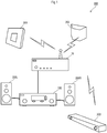
- Fig. 1 is a diagram illustrating an overview of a content data delivery system 900.
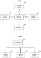
- Fig. 2 (A) is a diagram illustrating a connection relationship of each device.
- Fig. 2 (B) is a block diagram illustrating a flow of data at a time of delivery of content data.
- the content data delivery system 900 is provided with a wireless router 10, an AV receiver 100, a speaker device 301, a speaker device 302, and a speaker device 303.
- the AV receiver 100, the speaker device 301, the speaker device 302, and the speaker device 303 are network-connected to one another through the wireless router 10.
- the wireless router 10 and the AV receiver 100 are connected by a wired LAN (Local Area Network), and the wireless router 10 and each speaker device are connected by a wireless LAN.
- the connection of each device may be wireless or may be wired, and, as long as a mode of the connection enables communication, the mode is not limited to the mode of connection through a network.
- the AV receiver 100 serves as a server (a content data transmitting device), and delivers content data to the speaker device 301, the speaker device 302, and the speaker device 303 that each serve as a client (a content data receiving device).
- the wireless router 10 may serve as a server that delivers content data, and the AV receiver 100 may be a client.
- the wireless router 10 may serve as a server, and the AV receiver 100, the speaker device 301, the speaker device 302, and the speaker device 303 may each serve as a client.
- a predetermined device (a device specified by a user, for example) serves as a server and other devices each serve as a client.
- the content data delivery system 900 streams the content data that is being reproduced in the AV receiver 100 to the speaker device 301, the speaker device 302, and the speaker device 303, and realizes synchronous reproduction in all the devices.
- a user listens to audio that is being reproduced by the AV receiver 100 in a living room, for example, and, then, in a case of moving to another room (a bedroom, for example), can also listen to the audio by the speaker device 301 installed in the bedroom.
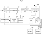
- Fig. 3 is a block diagram illustrating a main configuration of the AV receiver 100. It is to be noted that, in this example, while the AV receiver 100 serves as a server, in a case in which other devices other than the AV receiver 100 serve as a server, the other devices are to be provided with the configuration as illustrated in Fig. 3 .
- the AV receiver 100 is provided with an input I/F (interface) 101, a controller 102, a reproduction FIFO 103, a reproducing portion 104, a DSP 105, an output I/F 106, a delivery FIFO 107, and a communication I/F 108.
- the input I/F 101 includes an HDMI (registered trademark) terminal, a digital audio input terminal, or an analog audio input terminal, for example, and inputs content data, a digital audio signal, or an analog audio signal from the outside.
- HDMI registered trademark
- the content data is audio data encoded by MP3 and the like, for example.
- the input I/F 101 outputs input audio data to the controller 102.
- the input I/F 101 in a case in which an analog audio signal is input, converts the analog audio signal into a digital audio signal and outputs the digital audio signal to the controller 102.
- the content data may be input from a storage (NAS (Network Attached Storage) or the like, for example) of other devices through the communication I/F 108, may be input from an external server connected through the Internet, or may be input from an built-in storage such as an HDD (Hard Disk Drive).
- NAS Network Attached Storage
- HDD Hard Disk Drive
- the controller 102 converts the input audio data into the audio data as it is or audio data in a predetermined encoding method. In addition, the controller 102 outputs the audio data to the reproduction FIFO 103 and the delivery FIFO 107 as packet data. In addition, the controller 102, also in a case in which a digital audio signal is input, converts the digital audio signal into audio data in a predetermined encoding method, and outputs the audio data to the reproduction FIFO 103 and the delivery FIFO 107 as packet data.
- Fig. 5 illustrates an example of a structure of packet data.
- the packet data as illustrated in Fig. 5 is composed of a header and a body (audio data).
- the header includes information (Command) that indicates a type of a packet, information (Sequence) that indicates a number of a packet, information (Clock) that indicates reproduction timing, and various types of information (Re_trans_id) that indicates whether or not the packet is retransmission data.
- the Command may indicate that the packet is a packet of audio data and may indicate that the packet is a packet of other data (test data, for example).
- the Sequence is used to determine whether or not a client has received packet data in a correct sequence.
- the client in a case in which numbers included in the Sequence are discontinuous, determines that there is a loss of a packet and performs a retransmission request to a server.
- the Clock is information that indicates reproduction timing (reproduction time) of audio data.
- the server and the client perform the reproduction of received audio data based on the reproduction time indicated by the Clock. As a result, synchronous reproduction is realized.
- the Re_trans_id includes information that indicates whether or not the packet is packet data to the retransmission request.
- the controller 102 outputs the packet data as illustrated in Fig. 5 to the reproduction FIFO 103 and the delivery FIFO 107.
- the reproduction FIFO 103 is a reproduction temporary storage portion that holds packet data of a predetermined time and outputs the packet data in an input sequence.
- the delivery FIFO 107 is a delivery temporary storage portion that holds packet data of a predetermined time and outputs the packet data in an input sequence.
- the reproduction FIFO 103 and the delivery FIFO 107 have a capacity that is set in consideration of time (processing delay) required for processing of various processors provided in a subsequent stage.
- the reproduction FIFO 103 if the processing time of the reproducing portion 104 is 0.1 seconds, the processing time of the DSP 105 is 0.1 seconds, and the time (time in consideration of the retransmission request on a client side to be described below) required for delivering packet data is 1.8 seconds, has a capacity that is set to be equivalent to audio data of about 2 seconds in order to synchronize with the delivery.
- the delivery FIFO 107 may have a capacity that is set to be equivalent to audio data of about 0.2 seconds obtained by excluding the time required for delivery in order to synchronize with the reproduction.
- the content data delivery system 900 is able to realize synchronous reproduction in this manner.
- the packet data held in the reproduction FIFO 103 is output to the reproducing portion 104.
- the reproducing portion 104 based on the reproduction time included in the packet data, reproduces the audio data of the packet data and outputs a digital audio signal.
- the digital audio signal that has been reproduced by the reproducing portion 104 is subjected to predetermined signal processing (processing of adding a sound field effect by adding a pseudo reflected sound, for example) by the DSP 105 being a server side signal processing portion, and is output to the output I/F 106.
- predetermined signal processing processing of adding a sound field effect by adding a pseudo reflected sound, for example
- the digital audio signal that has been output from the output I/F 106 is input to a speaker 200L and a speaker 200R.
- the speaker 200L and the speaker 200R convert the input digital audio signal into an analog audio signal and amplify the analog audio signal.
- the speaker 200L and the speaker 200R input an amplified analog audio signal to an own speaker unit.
- the speaker 200L and the speaker 200R output sound according to audio data.
- the output I/F 106 and each speaker may be connected through a speaker cable (an analog audio line).
- a DAC Digital-to-Analog Converter
- an amplifying portion are arranged between the DSP 105 and the output I/F 106.
- the packet data to be output from the delivery FIFO 107 is delivered to the speaker device 301, the speaker device 302, and the speaker device 303 through the communication I/F 108 being a server side communication portion.
- Fig. 4 (A) is a block diagram illustrating a main configuration of the speaker device 301. Since the main configurations of other speaker device 302 and speaker device 303 are also similar, Fig. 4 illustrates the configuration of the speaker device 301 as a representative.
- the speaker device 301 is provided with a communication I/F 311, a buffer processing portion 312, a reproducing portion 313, a DSP 314, and an SS (a sound system) 315.
- the communication I/F 311 corresponds to a content data receiving portion, receives packet data delivered from the AV receiver 100 being a server, and inputs the packet data to the buffer processing portion 312.
- Fig. 4(B) is a block diagram illustrating a configuration of the buffer processing portion 312.
- the buffer processing portion 312 is provided with a controller 351, a buffer 352, and an FIFO 353.
- the controller 351 determines whether or not the packet data is received in the correct sequence. As described above, the packet data includes information (Sequence) that indicates a sequence. Therefore, the controller 351, in a case in which the numbers included in the Sequence are continuous, outputs received packet data to the FIFO 353 provided in a subsequent stage (a retransmission request of the controller 351 will be described below).
- the FIFO 353 has a capacity that is set corresponding to a time (time in consideration of a retransmission request) required for delivery of the packet data, the time having been set in the reproduction FIFO 103.
- the FIFO 353 has a capacity that is set to be equivalent to the audio data of 1.8 seconds.
- the digital audio signal that has been reproduced by the reproducing portion 313 is subjected to predetermined signal processing (processing of adding a sound field effect by adding a pseudo reflected sound, for example) by the DSP 314, and is output to the SS 315.
- the SS 315 is provided with a DAC, an amplifying portion, and a speaker unit. As a result, the sound according to the audio data delivered from the AV receiver 100 is output from the speaker unit of the speaker device 301, and synchronous reproduction is thus realized.
- the controller 351 determines that there is a loss of a packet and performs a retransmission request to the AV receiver 100.
- the controller 351 holds received new packet data in the buffer 352 until the packet data in the correct sequence is retransmitted.
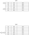
- Fig. 6 (A) is a block diagram illustrating a structure of the buffer 352.
- the buffer 352 an area for storing a plurality of pieces of packet data (6 pieces of packet data in this example) by identifying the structure of a transmission packet is set in advance.
- information (Valid) that indicates whether or not the packet data is a loss and the packet number (pkt_id) corresponding to the Sequence are indicated.
- the buffer 352 is brought into an empty state in a case in which the packet data is received in the correct sequence.
- the controller 35 in a case of receiving the packet data of packet number 005 after having received the packet data of packet number 002, for example, determines that the packet data of packet number 003 and packet number 004 have been lost, and, as indicated in Fig. 6(B) , stores the packet data of packet number 005 after ensuring a data area of packet numbers 003 and 004 in the buffer 352.
- the controller 351 to the AV receiver 100, performs a retransmission request of the packet data of packet number 003 and packet number 004 that have been lost.
- the controller 35 in a case of receiving the packet data of packet number 003 to the retransmission request, outputs the packet data of packet number 003 to the FIFO 353 in the subsequent stage and, as indicated in Fig. 7(A) , advances a RP (Read Pointer) to packet number 004.
- RP Read Pointer
- the controller 351 in a case of receiving the content data of packet number 004 to the retransmission request, outputs the packet data of packet number 004 to the FIFO 353 in the subsequent stage, and also further outputs the packet data of packet number 005 that has been held in the buffer 352 provided in the subsequent stage. Then, the controller 351, as illustrated in Fig. 7(B) , advances the RP (Read Pointer) after packet number 005. As a result, the buffer 352 is brought into an empty state.
- RP Read Pointer
- the controller 351 holds the received new packet data in the buffer 352 until the packet data in the correct sequence is retransmitted. Therefore, the controller 351, after performing a retransmission request, in a case in which packet data of packet number 006 is received, for example, stores the packet data of packet number 006 in the buffer 352, as illustrated in Fig. 8(A) .
- the controller 351 in a case in which the packet data that has been stored in the FIFO 353 in the subsequent stage becomes less than or equal to a reference amount and underflow of the FIFO 353 is detected, outputs valid packet data among the packet data held in the buffer 352, to the subsequent stage. In other words, as illustrated in Fig.
- packet number 005 and packet number 006 are output to the FIFO 353 in the subsequent stage.
- the FIFO 353 since having the capacity that is set to be equivalent to the audio data of 1.8 seconds, is able to handle the loss of the packet data of 1.8 seconds, but, in a case in which a loss exceeding 1.8 seconds occurs, the reproduction of audio data stops. Therefore, the controller 351 outputs next valid packet data to the subsequent stage so as to prevent the reproduction of audio data from stopping.
- the controller 35 after writing packet data being a substitute for packet number 003 and packet number 004 that have been lost, into a corresponding data portion of the buffer 352, may output the packet data to the subsequent stage.
- the packet data of packet number 005 is copied, and the copied packet data is written into a corresponding data portion of the buffer 352 and is output to the subsequent stage as packet data of packet number 003 and packet number 004.
- the packet data is data different from the original data, a loss as audio data is avoided and alternative data is data that has continuity in succession, so that the occurrence of noise sound due to a loss of audio data is able to be prevented.
- the controller 35 in a case of having received new packet data (that does not correspond to a retransmission request) in a state in which the capacity of the buffer 352 is filled up before a retransmission packet arrives and any more packet data is not able to be held, as illustrated in Fig. 9(B) , outputs currently valid packet data (packet number 005, packet number 006, packet number 007, and packet number 008 in this example) to the subsequent stage, and overwrites the packet data (packet number 003 in this example) of the oldest number with received packet data.
- the packet data of another packet number may be copied in place of the packet data of packet number 003 and packet number 004 that have been lost and may be output to the subsequent stage as data of these packet number 003 and packet number 004.
- the speaker device 301 in a state in which the continuity of the received packet data is ensured, outputs the received packet data to the subsequent stage as it is, and ensures real-time characteristics.
- the speaker device 301 only when the received packet data is discontinuous, holds the packet data in the buffer 352, and ensures the continuity by performing a retransmission request.
- the FIFO 353 is provided in the subsequent stage, even when a retransmission request is performed, the real-time characteristics are not impaired.
- the communication I/F 311 of the speaker device 301 receives packet data from the AV receiver 100 (S11).
- the controller 351 in a case of determining that the buffer is in an overflow state, as illustrated in Fig. 9 (A) and Fig. 9(B) , outputs the currently valid packet data to the subsequent stage (S13), and overwrites the packet data of the oldest number with the received packet data (S14).
- the packet data of other packet numbers may be copied and may be output to the subsequent stage as data of lost packet number 003.
- data having a data portion into which 0 is simply written is created, and may be output to the subsequent stage.
- the controller 35 determines whether or not the continuity of the received packet data with the FIFO 353 in the subsequent stage is ensured. If the continuity is ensured, the packet data is output to the FIFO 353 in the subsequent stage (S16). It is to be noted that the controller 351, in a case in which the received packet data is packet data corresponding to a retransmission request, stops the retransmission request of the packet data.
- the controller 35 in a case in which the numbers included in Sequence of the packet data are discontinuous, after ensuring a lost data area in the buffer 352, holds the received packet data in a corresponding portion of the buffer 352 (S17), and performs a retransmission request of the lost packet data (S18).
- the controller 351 regarding a retransmission request that has been performed in the past, in a case of having received no content data corresponding to the retransmission request even after a predetermined time elapses, may perform an operation to perform the retransmission request once again.
- Fig. 11 is a flow chart showing an operation at a time of detection of underflow of the FIFO 353.
- the controller 35 in a case in which the packet data that has been stored in the FIFO 353 becomes less than or equal to a reference amount and underflow is detected (S21), outputs valid packet data among the packet data that has been held in the buffer 352, to the subsequent stage (S22) .
- the controller 35 in a case in which the packet data that has been stored in the FIFO 353 becomes less than or equal to a reference amount and the underflow is detected (S21), may copy the valid packet data (S32) among the packet data held in the buffer 352, may create packet data of continuous packet numbers, and may output the packet data to the subsequent stage (S33).
- the packet data of packet number 005 is copied, the copied packet data is output to the subsequent stage as packet data of packet number 003 and packet number 004.
- the content data receiving device in a state in which the continuity of content data is ensured, outputs received content data to the subsequent stage as it is, and ensures real-time characteristics.
- the content data receiving device only when the received content data is discontinuous, holds the content data in the buffer and ensures the continuity by performing a retransmission request.
- the controller when performing a retransmission request, assigns a storage area of the content data for which the retransmission request is performed, to the buffer, and, in a case of receiving content data corresponding to the retransmission request, preferably holds received content data in an assigned area.
- the content data receiving device is preferably provided with a temporary storage portion (FIFO) that temporarily holds the content data that has been output from the controller and outputs the content data that has been held in an input sequence.
- FIFO temporary storage portion
- the content data receiving device by including the FIFO, is able to ensure real-time characteristics while ensuring continuity, also when performing a retransmission request.
- the controller in a case in which the content data held in the FIFO becomes less than or equal to a reference amount, outputs valid content data among the content data held in the buffer, to the subsequent stage.
- the controller in the case in which the content data held in the FIFO becomes less than or equal to a reference amount, may copy the valid data among the content data held in the buffer and may output the valid content data to the subsequent stage as content data in a continuous sequence.
- the data is data different from audio data of a regular sequence, the same data as the audio data to be output later is reproduced instead, so that a possibility that noise sound due to lost audio data occurs is able to be reduced.
- the controller in a case in which the capacity of the buffer becomes greater than or equal to a reference amount, overwrites data of the oldest sequence with newly received content data.
- the controller in a case of receiving no content data corresponding to a retransmission request even after a predetermined time elapses, preferably performs the retransmission request once again.
- the content data delivery system 900 may perform synchronous reproduction of the AV receiver 100 and a part of the speaker devices, for example, or may perform synchronous reproduction of the AV receiver 100 and some speaker devices specified by a user, for example.
- the content data delivery system 900 may be able to be configured by the AV receiver 100 and one speaker device, and may perform synchronous reproduction of the AV receiver 100 and the one speaker device.
Landscapes
- Engineering & Computer Science (AREA)
- Theoretical Computer Science (AREA)
- General Engineering & Computer Science (AREA)
- Physics & Mathematics (AREA)
- General Physics & Mathematics (AREA)
- Signal Processing (AREA)
- Multimedia (AREA)
- Human Computer Interaction (AREA)
- Computer Networks & Wireless Communication (AREA)
- Computer Hardware Design (AREA)
- Communication Control (AREA)
- Two-Way Televisions, Distribution Of Moving Picture Or The Like (AREA)
- Computer And Data Communications (AREA)
- Data Exchanges In Wide-Area Networks (AREA)
Abstract
Description
- A preferred embodiment of the present invention relates to a content data receiving device that receives content data.
- Conventionally, a content reproduction system that streams content data from a server to a plurality of clients and reproduces the content data at each client has been known (see Patent Literature 1, for example).
- A delivery system of Patent Literature 1 streams, as content data, compressed audio data such as MP3, from a server to each client. As a result, a user can listen to the audio data stored in a storage of a server, in every room of a house.
- Patent Literature 1: Japanese Unexamined Patent Application Publication No.
2006-195838 - However, the content data delivery system of Patent Literature 1 has not considered a loss of audio data at a time of delivery. If there is a loss of audio data, continuity as the audio data is lost. If the continuity of the audio data is lost, sound is interrupted or noise sound occurs, which causes an uncomfortable situation for a user.
- On the other hand, if a server transmits audio data a plurality of times in advance in consideration of the loss of audio data, a time required for transmission becomes larger and a time until reproduction is started on a client side is delayed, which impairs real-time characteristics.
- In view of the foregoing, an object of a preferred embodiment of the present invention is to provide a content data receiving device that is able to ensure real-time characteristics while ensuring the continuity of the content data to be delivered.
- A content data receiving device is provided with a receiving portion, a buffer, and a controller. The receiving portion receives content data including information indicating a sequence. The buffer holds the content data that has been received by the receiving portion. The controller, in a case in which the sequence included in the content data that has been received by the receiving portion is discontinuous, performs a retransmission request to a transmission side after causing the buffer to hold the content data, causes the buffer to keep holding the content data that has been received by the receiving portion until receiving content data in a continuous sequence, and, in a case of receiving the content data in a continuous sequence, outputs the content data to a subsequent stage so that the sequence is continuous.
- According to a preferred embodiment of the present invention, real-time characteristics are able to be ensured while the continuity of content data to be delivered is also able to be ensured.
-
-
Fig. 1 is a diagram illustrating an overview of a content data delivery system. -
Fig. 2 (A) is a diagram illustrating a connection relationship, andFig. 2(B) is a block diagram illustrating a flow of data at a time of delivery of content data. -
Fig. 3 is a block diagram illustrating a configuration of an AV receiver. -
Fig. 4(A) is a block diagram illustrating a configuration of a speaker device andFig. 4(B) is a block diagram illustrating a configuration of a buffer processing portion. -
Fig. 5 illustrates a structure of packet data. -
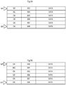
Fig. 6 (A) is a diagram illustrating a structure of a buffer, andFig. 6(B) is a diagram illustrating a structure of a buffer when loss packet data is detected. -
Fig. 7 (A) and Fig. 7 (B) are diagrams illustrating a structure of a buffer when packet data to a retransmission request is received. -
Fig. 8(A) is a diagram illustrating a structure of a buffer when packet data other than the packet data to the retransmission request is received, andFig. 8(B) is a diagram illustrating a structure of a buffer in a case in which underflow is detected in an FIFO provided in a subsequent stage. -
Fig. 9(A) is a diagram illustrating a structure of a buffer in a state in which an entire area is filled, andFig. 9(B) is a diagram illustrating a structure of a buffer at a time of overflow. -
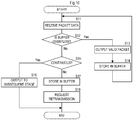
Fig. 10 is a flow chart showing an operation of the speaker device. -
Fig. 11 is a flow chart showing an operation of the speaker device at a time of detection of underflow. -
Fig. 12 is a flow chart showing an operation of the speaker device at the time of detection of underflow. -
Fig. 1 is a diagram illustrating an overview of a contentdata delivery system 900.Fig. 2 (A) is a diagram illustrating a connection relationship of each device.Fig. 2 (B) is a block diagram illustrating a flow of data at a time of delivery of content data. - As illustrated in
Fig. 1 , the contentdata delivery system 900 is provided with awireless router 10, anAV receiver 100, aspeaker device 301, aspeaker device 302, and aspeaker device 303. As illustrated inFig. 2 (A) , theAV receiver 100, thespeaker device 301, thespeaker device 302, and thespeaker device 303 are network-connected to one another through thewireless router 10. In this example, thewireless router 10 and theAV receiver 100 are connected by a wired LAN (Local Area Network), and thewireless router 10 and each speaker device are connected by a wireless LAN. However, the connection of each device may be wireless or may be wired, and, as long as a mode of the connection enables communication, the mode is not limited to the mode of connection through a network. - As illustrated in
Fig. 2(B) , in the contentdata delivery system 900 of this example, theAV receiver 100 serves as a server (a content data transmitting device), and delivers content data to thespeaker device 301, thespeaker device 302, and thespeaker device 303 that each serve as a client (a content data receiving device). However, thewireless router 10 may serve as a server that delivers content data, and theAV receiver 100 may be a client. In addition, thewireless router 10 may serve as a server, and theAV receiver 100, thespeaker device 301, thespeaker device 302, and thespeaker device 303 may each serve as a client. In other words, in the content data delivery system, among network-connected devices, a predetermined device (a device specified by a user, for example) serves as a server and other devices each serve as a client. - The content
data delivery system 900 streams the content data that is being reproduced in theAV receiver 100 to thespeaker device 301, thespeaker device 302, and thespeaker device 303, and realizes synchronous reproduction in all the devices. Thus, a user listens to audio that is being reproduced by theAV receiver 100 in a living room, for example, and, then, in a case of moving to another room (a bedroom, for example), can also listen to the audio by thespeaker device 301 installed in the bedroom. -
Fig. 3 is a block diagram illustrating a main configuration of theAV receiver 100. It is to be noted that, in this example, while theAV receiver 100 serves as a server, in a case in which other devices other than theAV receiver 100 serve as a server, the other devices are to be provided with the configuration as illustrated inFig. 3 . - The
AV receiver 100 is provided with an input I/F (interface) 101, acontroller 102, a reproduction FIFO 103, a reproducingportion 104, aDSP 105, an output I/F 106, adelivery FIFO 107, and a communication I/F 108. - The input I/
F 101 includes an HDMI (registered trademark) terminal, a digital audio input terminal, or an analog audio input terminal, for example, and inputs content data, a digital audio signal, or an analog audio signal from the outside. - The content data is audio data encoded by MP3 and the like, for example. The input I/
F 101 outputs input audio data to thecontroller 102. In addition, the input I/F 101, in a case in which an analog audio signal is input, converts the analog audio signal into a digital audio signal and outputs the digital audio signal to thecontroller 102. - It is to be noted that the content data may be input from a storage (NAS (Network Attached Storage) or the like, for example) of other devices through the communication I/
F 108, may be input from an external server connected through the Internet, or may be input from an built-in storage such as an HDD (Hard Disk Drive). - The
controller 102 converts the input audio data into the audio data as it is or audio data in a predetermined encoding method. In addition, thecontroller 102 outputs the audio data to the reproduction FIFO 103 and the delivery FIFO 107 as packet data. In addition, thecontroller 102, also in a case in which a digital audio signal is input, converts the digital audio signal into audio data in a predetermined encoding method, and outputs the audio data to the reproduction FIFO 103 and thedelivery FIFO 107 as packet data. -
Fig. 5 illustrates an example of a structure of packet data. The packet data as illustrated inFig. 5 is composed of a header and a body (audio data). The header includes information (Command) that indicates a type of a packet, information (Sequence) that indicates a number of a packet, information (Clock) that indicates reproduction timing, and various types of information (Re_trans_id) that indicates whether or not the packet is retransmission data. - The Command may indicate that the packet is a packet of audio data and may indicate that the packet is a packet of other data (test data, for example).
- The Sequence is used to determine whether or not a client has received packet data in a correct sequence. The client, in a case in which numbers included in the Sequence are discontinuous, determines that there is a loss of a packet and performs a retransmission request to a server.
- The Clock is information that indicates reproduction timing (reproduction time) of audio data. The server and the client perform the reproduction of received audio data based on the reproduction time indicated by the Clock. As a result, synchronous reproduction is realized.
- The Re_trans_id includes information that indicates whether or not the packet is packet data to the retransmission request.
- The
controller 102 outputs the packet data as illustrated inFig. 5 to thereproduction FIFO 103 and thedelivery FIFO 107. - The
reproduction FIFO 103 is a reproduction temporary storage portion that holds packet data of a predetermined time and outputs the packet data in an input sequence. Thedelivery FIFO 107 is a delivery temporary storage portion that holds packet data of a predetermined time and outputs the packet data in an input sequence. Thereproduction FIFO 103 and thedelivery FIFO 107 have a capacity that is set in consideration of time (processing delay) required for processing of various processors provided in a subsequent stage. For example, thereproduction FIFO 103, if the processing time of the reproducingportion 104 is 0.1 seconds, the processing time of theDSP 105 is 0.1 seconds, and the time (time in consideration of the retransmission request on a client side to be described below) required for delivering packet data is 1.8 seconds, has a capacity that is set to be equivalent to audio data of about 2 seconds in order to synchronize with the delivery. Thedelivery FIFO 107 may have a capacity that is set to be equivalent to audio data of about 0.2 seconds obtained by excluding the time required for delivery in order to synchronize with the reproduction. - As a result, it becomes possible to match the reproduction timing of the
AV receiver 100 being a server and the reproduction timing of the audio data in each speaker device (a delivery destination of data) being a client. The contentdata delivery system 900 is able to realize synchronous reproduction in this manner. - The packet data held in the
reproduction FIFO 103 is output to the reproducingportion 104. The reproducingportion 104, based on the reproduction time included in the packet data, reproduces the audio data of the packet data and outputs a digital audio signal. - The digital audio signal that has been reproduced by the reproducing
portion 104 is subjected to predetermined signal processing (processing of adding a sound field effect by adding a pseudo reflected sound, for example) by theDSP 105 being a server side signal processing portion, and is output to the output I/F 106. - The digital audio signal that has been output from the output I/
F 106 is input to aspeaker 200L and aspeaker 200R. Thespeaker 200L and thespeaker 200R convert the input digital audio signal into an analog audio signal and amplify the analog audio signal. Thespeaker 200L and thespeaker 200R input an amplified analog audio signal to an own speaker unit. As a result, thespeaker 200L and thespeaker 200R output sound according to audio data. It is to be noted that the output I/F 106 and each speaker may be connected through a speaker cable (an analog audio line). In such a case, a DAC (Digital-to-Analog Converter) and an amplifying portion are arranged between theDSP 105 and the output I/F 106. - On the other hand, the packet data to be output from the
delivery FIFO 107 is delivered to thespeaker device 301, thespeaker device 302, and thespeaker device 303 through the communication I/F 108 being a server side communication portion. -
Fig. 4 (A) is a block diagram illustrating a main configuration of thespeaker device 301. Since the main configurations ofother speaker device 302 andspeaker device 303 are also similar,Fig. 4 illustrates the configuration of thespeaker device 301 as a representative. - The
speaker device 301 is provided with a communication I/F 311, abuffer processing portion 312, a reproducingportion 313, aDSP 314, and an SS (a sound system) 315. - The communication I/
F 311 corresponds to a content data receiving portion, receives packet data delivered from theAV receiver 100 being a server, and inputs the packet data to thebuffer processing portion 312. -
Fig. 4(B) is a block diagram illustrating a configuration of thebuffer processing portion 312. Thebuffer processing portion 312 is provided with acontroller 351, abuffer 352, and anFIFO 353. - The
controller 351 determines whether or not the packet data is received in the correct sequence. As described above, the packet data includes information (Sequence) that indicates a sequence. Therefore, thecontroller 351, in a case in which the numbers included in the Sequence are continuous, outputs received packet data to theFIFO 353 provided in a subsequent stage (a retransmission request of thecontroller 351 will be described below). - The
FIFO 353 has a capacity that is set corresponding to a time (time in consideration of a retransmission request) required for delivery of the packet data, the time having been set in thereproduction FIFO 103. In other words, theFIFO 353 has a capacity that is set to be equivalent to the audio data of 1.8 seconds. - The reproducing
portion 313, based on the reproduction time of the packet data output from theFIFO 353, reproduces the audio data of the packet data and outputs a digital audio signal. - The digital audio signal that has been reproduced by the reproducing
portion 313 is subjected to predetermined signal processing (processing of adding a sound field effect by adding a pseudo reflected sound, for example) by theDSP 314, and is output to theSS 315. TheSS 315 is provided with a DAC, an amplifying portion, and a speaker unit. As a result, the sound according to the audio data delivered from theAV receiver 100 is output from the speaker unit of thespeaker device 301, and synchronous reproduction is thus realized. - On the other hand, the
controller 351, in a case in which the numbers included in the Sequence are discontinuous, determines that there is a loss of a packet and performs a retransmission request to theAV receiver 100. Thecontroller 351 holds received new packet data in thebuffer 352 until the packet data in the correct sequence is retransmitted. -
Fig. 6 (A) is a block diagram illustrating a structure of thebuffer 352. In thebuffer 352, an area for storing a plurality of pieces of packet data (6 pieces of packet data in this example) by identifying the structure of a transmission packet is set in advance. In thebuffer 352, for each piece of the packet data (DATA), information (Valid) that indicates whether or not the packet data is a loss and the packet number (pkt_id) corresponding to the Sequence are indicated. Thebuffer 352 is brought into an empty state in a case in which the packet data is received in the correct sequence. - In the present preferred embodiment, the
controller 351, in a case of receiving the packet data ofpacket number 005 after having received the packet data of packet number 002, for example, determines that the packet data ofpacket number 003 andpacket number 004 have been lost, and, as indicated inFig. 6(B) , stores the packet data ofpacket number 005 after ensuring a data area ofpacket numbers buffer 352. In addition, thecontroller 351, to theAV receiver 100, performs a retransmission request of the packet data ofpacket number 003 andpacket number 004 that have been lost. - It is to be noted that, since the
controller 351, in thebuffer 352, allocates a storage area ofpacket number 003 and packet number 004 (Valid=NG) as illustrated inFig. 6(B) after identifying (the size of the data portion is 1.4 KB, for example) the structure of a transmission packet; for example, after performing a retransmission request, even when content data ofpacket number 004 is received in advance to the retransmission request, thecontroller 351 is able to store the content data ofpacket number 004 in an area forpacket number 004 that is allocated in thebuffer 352. - On the other hand, the
controller 351, in a case of receiving the packet data ofpacket number 003 to the retransmission request, outputs the packet data ofpacket number 003 to theFIFO 353 in the subsequent stage and, as indicated inFig. 7(A) , advances a RP (Read Pointer) topacket number 004. - Then, the
controller 351, in a case of receiving the content data ofpacket number 004 to the retransmission request, outputs the packet data ofpacket number 004 to theFIFO 353 in the subsequent stage, and also further outputs the packet data ofpacket number 005 that has been held in thebuffer 352 provided in the subsequent stage. Then, thecontroller 351, as illustrated inFig. 7(B) , advances the RP (Read Pointer) afterpacket number 005. As a result, thebuffer 352 is brought into an empty state. - As described above, the
controller 351 holds the received new packet data in thebuffer 352 until the packet data in the correct sequence is retransmitted. Therefore, thecontroller 351, after performing a retransmission request, in a case in which packet data ofpacket number 006 is received, for example, stores the packet data ofpacket number 006 in thebuffer 352, as illustrated inFig. 8(A) . In the present preferred embodiment, thecontroller 351, in a case in which the packet data that has been stored in theFIFO 353 in the subsequent stage becomes less than or equal to a reference amount and underflow of theFIFO 353 is detected, outputs valid packet data among the packet data held in thebuffer 352, to the subsequent stage. In other words, as illustrated inFig. 8(B) ,packet number 005 andpacket number 006 are output to theFIFO 353 in the subsequent stage. TheFIFO 353, since having the capacity that is set to be equivalent to the audio data of 1.8 seconds, is able to handle the loss of the packet data of 1.8 seconds, but, in a case in which a loss exceeding 1.8 seconds occurs, the reproduction of audio data stops. Therefore, thecontroller 351 outputs next valid packet data to the subsequent stage so as to prevent the reproduction of audio data from stopping. - It is to be noted that, at this time, the
controller 351, after writing packet data being a substitute forpacket number 003 andpacket number 004 that have been lost, into a corresponding data portion of thebuffer 352, may output the packet data to the subsequent stage. For example, the packet data ofpacket number 005 is copied, and the copied packet data is written into a corresponding data portion of thebuffer 352 and is output to the subsequent stage as packet data ofpacket number 003 andpacket number 004. As a result, while the packet data is data different from the original data, a loss as audio data is avoided and alternative data is data that has continuity in succession, so that the occurrence of noise sound due to a loss of audio data is able to be prevented. - On the other hand, the
controller 351, as illustrated inFig. 9(A) , in a case of having received new packet data (that does not correspond to a retransmission request) in a state in which the capacity of thebuffer 352 is filled up before a retransmission packet arrives and any more packet data is not able to be held, as illustrated inFig. 9(B) , outputs currently valid packet data (packet number 005,packet number 006,packet number 007, andpacket number 008 in this example) to the subsequent stage, and overwrites the packet data (packet number 003 in this example) of the oldest number with received packet data. - It is to be noted that, this time again, the packet data of another packet number (
packet number 005, for example) may be copied in place of the packet data ofpacket number 003 andpacket number 004 that have been lost and may be output to the subsequent stage as data of thesepacket number 003 andpacket number 004. - As described above, the
speaker device 301, in a state in which the continuity of the received packet data is ensured, outputs the received packet data to the subsequent stage as it is, and ensures real-time characteristics. On the other hand, thespeaker device 301, only when the received packet data is discontinuous, holds the packet data in thebuffer 352, and ensures the continuity by performing a retransmission request. In addition, since theFIFO 353 is provided in the subsequent stage, even when a retransmission request is performed, the real-time characteristics are not impaired. - Subsequently, a description will be made of a series of the above described operations with reference to the flow chart of
Fig. 10 . While the operations of thespeaker device 301 are described in this example, other speaker devices also perform the same operations. - To begin with, the communication I/
F 311 of thespeaker device 301 receives packet data from the AV receiver 100 (S11). Thecontroller 351 of thebuffer processing portion 312, when receiving the packet data from the communication I/F 311, confirms the capacity of the buffer 352 (S12). Thecontroller 351, in a case of determining that the buffer is in an overflow state, as illustrated inFig. 9 (A) and Fig. 9(B) , outputs the currently valid packet data to the subsequent stage (S13), and overwrites the packet data of the oldest number with the received packet data (S14). At this time, in a case in which there is packet data of lost packet number, the packet data of other packet numbers may be copied and may be output to the subsequent stage as data of lostpacket number 003. In addition, data having a data portion into which 0 is simply written is created, and may be output to the subsequent stage. - The
controller 351, in a case of determining that the capacity of thebuffer 352 is not filled up, determines whether or not the continuity of the received packet data with theFIFO 353 in the subsequent stage is ensured. If the continuity is ensured, the packet data is output to theFIFO 353 in the subsequent stage (S16). It is to be noted that thecontroller 351, in a case in which the received packet data is packet data corresponding to a retransmission request, stops the retransmission request of the packet data. - On the other hand, the
controller 351, in a case in which the numbers included in Sequence of the packet data are discontinuous, after ensuring a lost data area in thebuffer 352, holds the received packet data in a corresponding portion of the buffer 352 (S17), and performs a retransmission request of the lost packet data (S18). - It is to be noted that the
controller 351, regarding a retransmission request that has been performed in the past, in a case of having received no content data corresponding to the retransmission request even after a predetermined time elapses, may perform an operation to perform the retransmission request once again. -
Fig. 11 is a flow chart showing an operation at a time of detection of underflow of theFIFO 353. Thecontroller 351, in a case in which the packet data that has been stored in theFIFO 353 becomes less than or equal to a reference amount and underflow is detected (S21), outputs valid packet data among the packet data that has been held in thebuffer 352, to the subsequent stage (S22) . - The
controller 351, as illustrated inFig. 12 , in a case in which the packet data that has been stored in theFIFO 353 becomes less than or equal to a reference amount and the underflow is detected (S21), may copy the valid packet data (S32) among the packet data held in thebuffer 352, may create packet data of continuous packet numbers, and may output the packet data to the subsequent stage (S33). As described above, for example, the packet data ofpacket number 005 is copied, the copied packet data is output to the subsequent stage as packet data ofpacket number 003 andpacket number 004. As a result, since a loss as audio data is avoided, the occurrence of noise sound due to a loss of audio data is able to be prevented. - As described above, the content data receiving device, in a state in which the continuity of content data is ensured, outputs received content data to the subsequent stage as it is, and ensures real-time characteristics. The content data receiving device, only when the received content data is discontinuous, holds the content data in the buffer and ensures the continuity by performing a retransmission request.
- It is to be noted that, in a case in which a plurality of pieces of content data are lost, even when a retransmission request is performed, content data having continuity is not necessarily received immediately. Thus, the controller, when performing a retransmission request, assigns a storage area of the content data for which the retransmission request is performed, to the buffer, and, in a case of receiving content data corresponding to the retransmission request, preferably holds received content data in an assigned area.
- In addition, the content data receiving device is preferably provided with a temporary storage portion (FIFO) that temporarily holds the content data that has been output from the controller and outputs the content data that has been held in an input sequence. The content data receiving device, by including the FIFO, is able to ensure real-time characteristics while ensuring continuity, also when performing a retransmission request. In such a case, the controller, in a case in which the content data held in the FIFO becomes less than or equal to a reference amount, outputs valid content data among the content data held in the buffer, to the subsequent stage.
- Alternatively, the controller, in the case in which the content data held in the FIFO becomes less than or equal to a reference amount, may copy the valid data among the content data held in the buffer and may output the valid content data to the subsequent stage as content data in a continuous sequence. In such a case, although the data is data different from audio data of a regular sequence, the same data as the audio data to be output later is reproduced instead, so that a possibility that noise sound due to lost audio data occurs is able to be reduced.
- It is to be noted that the controller, in a case in which the capacity of the buffer becomes greater than or equal to a reference amount, overwrites data of the oldest sequence with newly received content data.
- In addition, the controller, in a case of receiving no content data corresponding to a retransmission request even after a predetermined time elapses, preferably performs the retransmission request once again.
- In addition, while, in the present preferred embodiment, an example in which synchronous reproduction is realized in all the devices of the
AV receiver 100, thespeaker device 301, thespeaker device 302, and thespeaker device 303 is illustrated, the contentdata delivery system 900 may perform synchronous reproduction of theAV receiver 100 and a part of the speaker devices, for example, or may perform synchronous reproduction of theAV receiver 100 and some speaker devices specified by a user, for example. In addition, the contentdata delivery system 900 may be able to be configured by theAV receiver 100 and one speaker device, and may perform synchronous reproduction of theAV receiver 100 and the one speaker device. - The foregoing preferred embodiments are illustrative in all points and should not be construed to limit the present invention. The scope of the present invention is defined not by the foregoing preferred embodiment but by the following claims. Further, the scope of the present invention is intended to include all modifications within the scopes of the claims and within the meanings and scopes of equivalents.
-
- 10 - Wireless router
- 100 - AV receiver
- 101 - Input I/F
- 102 - Controller
- 103 - Reproduction FIFO
- 104 - Reproducing portion
- 105 - DSP
- 106 - Output I/F
- 107 - Delivery FIFO
- 108 - Communication I/F
- 200L, 200R - Speaker
- 301, 302, 303 - Speaker device
- 311 - Communication I/F
- 312 - Buffer processing portion
- 313 - Reproducing portion
- 314 - DSP
- 315 - SS
- 351 - Controller
- 352 - Buffer
- 353 - FIFO
- 900 - Content data delivery system
Claims (13)
- A content data receiving device comprising:a receiving portion receiving content data including information indicating a sequence;a buffer holding the content data that has been received by the receiving portion; anda controller configured to, in a case in which the sequence included in the content data that has been received by the receiving portion is discontinuous, perform a retransmission request to a transmission side after causing the buffer to hold the content data, cause the buffer to keep holding the content data that has been received by the receiving portion until receiving content data in a continuous sequence, and, in a case of receiving the content data in a continuous sequence, output the content data to a subsequent stage so that the sequence is continuous.
- The content data receiving device according to claim 1, wherein the controller, in a case in which the sequence included in the content data that has been received by the receiving portion is continuous, outputs the content data without holding the content data in the buffer.
- The content data receiving device according to claim 1 or 2, wherein the controller, when performing the retransmission request, assigns a storage area of content data for which the retransmission request is performed, to the buffer, and, in a case of receiving content data corresponding to the retransmission request, holds received content data in the assigned area.
- The content data receiving device according to any one of claims 1 to 3, comprising a temporary storage portion temporarily holding the content data that has been output from the controller and outputting the content data that has been held in an input sequence, wherein the controller, in a case in which the content data that has been held in the temporary storage portion becomes less than or equal to a reference amount, outputs valid content data among the content data that has been held in the buffer, to the subsequent stage.
- The content data receiving device according to any one of claims 1 to 3, comprising a temporary storage portion temporarily holding the content data that has been output from the controller and outputting the content data that has been held in an input sequence, wherein the controller, in a case in which the content data that has been held in the temporary storage portion becomes less than or equal to a reference amount, copies valid content data among the content data that has been held in the buffer, and outputs the valid content data as content data in a continuous sequence, to the subsequent stage.
- The content data receiving device according to any one of claims 1 to 5, wherein the controller, in a case in which a capacity of the buffer becomes greater than or equal to a reference amount, overwrites data of an oldest sequence with newly received content data.
- The content data receiving device according to any one of claims 1 to 6, wherein the controller, in a case of receiving no content data corresponding to the retransmission request even after a predetermined time elapses, performs the retransmission request again.
- The content data receiving device according to any one of claims 1 to 7, comprising a reproducing portion reproducing the content data that the controller has output.
- A content data delivery system comprising:the content data receiving device according to any one of claims 1 to 8; anda transmitting device transmitting the content data to the content data receiving device.
- The content data delivery system according to claim 9, wherein the transmitting device comprises a second reproducing portion also reproducing the content data to be transmitted to the content data receiving device, in an own device.
- The content data delivery system according to claim 10, wherein the transmitting device further comprises a reproduction temporary storage portion to which a capacity to hold content data of a time corresponding to the retransmission request is set, the reproduction temporary storage portion being provided in a stage preceding the reproducing portion.
- The content data delivery system according to claim 10 or 11, wherein the transmitting device further comprises a delivery temporary storage portion to which a capacity corresponding to a processing time of the second reproducing portion is set.
- A content data receiving method comprising:receiving content data including information indicating a sequence;in a case in which the sequence included in received content data is discontinuous, holding the content data and performing a retransmission request to a transmission side;holding the received content data until receiving content data in a continuous sequence; andin a case of receiving the content data in a continuous sequence, outputting the content data to a subsequent stage so that the sequence is continuous.
Applications Claiming Priority (2)
| Application Number | Priority Date | Filing Date | Title |
|---|---|---|---|
| JP2015161091A JP6578808B2 (en) | 2015-08-18 | 2015-08-18 | Content data receiving device |
| PCT/JP2016/073060 WO2017030014A1 (en) | 2015-08-18 | 2016-08-05 | Content data reception device, content data delivery system, and content data reception method |
Publications (2)
| Publication Number | Publication Date |
|---|---|
| EP3340062A1 true EP3340062A1 (en) | 2018-06-27 |
| EP3340062A4 EP3340062A4 (en) | 2019-03-20 |
Family
ID=58050965
Family Applications (1)
| Application Number | Title | Priority Date | Filing Date |
|---|---|---|---|
| EP16837004.7A Ceased EP3340062A4 (en) | 2015-08-18 | 2016-08-05 | CONTENT DATA RECEIVING DEVICE, CONTENT DATA DISTRIBUTION SYSTEM, AND CONTENT DATA RECEIVING METHOD |
Country Status (4)
| Country | Link |
|---|---|
| US (1) | US10496325B2 (en) |
| EP (1) | EP3340062A4 (en) |
| JP (1) | JP6578808B2 (en) |
| WO (1) | WO2017030014A1 (en) |
Family Cites Families (16)
| Publication number | Priority date | Publication date | Assignee | Title |
|---|---|---|---|---|
| JPH0458646A (en) * | 1990-06-28 | 1992-02-25 | Toshiba Corp | Buffer management system |
| JPWO2002023908A1 (en) * | 2000-09-11 | 2004-01-29 | 村瀬 洋太郎 | Network video / audio distribution method, device thereof, and video / audio creation method |
| SE0103506D0 (en) * | 2001-10-19 | 2001-10-19 | Ericsson Telefon Ab L M | HARQ stall avoidance |
| US7542986B2 (en) * | 2002-03-26 | 2009-06-02 | Hewlett-Packard Development Company, L.P. | System and method for maintaining order for a replicated multi-unit I/O stream |
| JP2003333488A (en) * | 2002-05-09 | 2003-11-21 | Mitsubishi Electric Corp | Streaming data playback method and streaming data playback method |
| WO2003096617A2 (en) * | 2002-05-10 | 2003-11-20 | Interdigital Technology Corporation | Prioritization of protocol data for retransmission |
| US6901063B2 (en) * | 2002-05-13 | 2005-05-31 | Qualcomm, Incorporated | Data delivery in conjunction with a hybrid automatic retransmission mechanism in CDMA communication systems |
| GB0230301D0 (en) * | 2002-12-30 | 2003-02-05 | Nokia Corp | Streaming media |
| US7603475B2 (en) * | 2003-03-31 | 2009-10-13 | Alcatel-Lucent Usa Inc. | Method for flow control in a communication system |
| US7969901B2 (en) * | 2004-08-12 | 2011-06-28 | Lantiq Deutschland Gmbh | Method and device for compensating for runtime fluctuations of data packets |
| JP4622531B2 (en) | 2005-01-14 | 2011-02-02 | ヤマハ株式会社 | Server apparatus, client apparatus, streaming distribution system, and content recording method |
| WO2008032660A1 (en) * | 2006-09-11 | 2008-03-20 | Panasonic Corporation | Image decoding device, image decoding method, image decoding system, and system lsi |
| WO2008041329A1 (en) * | 2006-10-04 | 2008-04-10 | Fujitsu Limited | Data transfer method |
| US8331386B2 (en) * | 2007-02-07 | 2012-12-11 | Agere Systems Llc | CRC checking and MAC-HS processing in an HSDPA-compatible receiver in a 3G wireless network |
| CN103141062A (en) * | 2010-10-07 | 2013-06-05 | Nec卡西欧移动通信株式会社 | Data readout device, communication device, data readout method, and program |
| US9876612B1 (en) * | 2017-02-06 | 2018-01-23 | Naveen Maveli | Data bandwidth overhead reduction in a protocol based communication over a wide area network (WAN) |
-
2015
- 2015-08-18 JP JP2015161091A patent/JP6578808B2/en active Active
-
2016
- 2016-08-05 EP EP16837004.7A patent/EP3340062A4/en not_active Ceased
- 2016-08-05 WO PCT/JP2016/073060 patent/WO2017030014A1/en not_active Ceased
-
2018
- 2018-02-15 US US15/897,918 patent/US10496325B2/en active Active
Also Published As
| Publication number | Publication date |
|---|---|
| US20180173458A1 (en) | 2018-06-21 |
| JP6578808B2 (en) | 2019-09-25 |
| WO2017030014A1 (en) | 2017-02-23 |
| EP3340062A4 (en) | 2019-03-20 |
| US10496325B2 (en) | 2019-12-03 |
| JP2017041695A (en) | 2017-02-23 |
Similar Documents
| Publication | Publication Date | Title |
|---|---|---|
| US7720985B2 (en) | Content receiving apparatus and content receiving method | |
| US9348780B2 (en) | Circuit and methods to use an audio interface to program a device within an audio stream | |
| US20160057390A1 (en) | Obtaining replay of audio during a conference session | |
| WO2017161998A1 (en) | Video processing method and device and computer storage medium | |
| JP2016522590A5 (en) | ||
| US9788140B2 (en) | Time to play | |
| JP6516767B2 (en) | MMTP decapsulation buffer signaling and operation | |
| US10686897B2 (en) | Method and system for transmission and low-latency real-time output and/or processing of an audio data stream | |
| US20170331756A1 (en) | Interactivity driven error correction for audio communication in lossy packet-switched networks | |
| WO2019100475A1 (en) | Data transmission method, apparatus and device, and storage medium | |
| US9912617B2 (en) | Method and apparatus for voice communication based on voice activity detection | |
| CN103647727A (en) | Audio and video transmission control method and audio and video transmission control device | |
| US10496325B2 (en) | Content data receiving device, content data delivery system, and content data receiving method | |
| CN107113283A (en) | The method that problematic pattern is handled in low latency multi-media streaming transmission environment | |
| WO2010143550A1 (en) | Information processing device, method therefor, and program | |
| JP6582722B2 (en) | Content distribution device | |
| US20250088804A1 (en) | Zone-based functionality and operation of audio amplifiers | |
| EP3340526A1 (en) | Content data delivery system and content data delivery method | |
| US9306824B2 (en) | Communication control apparatus, communication control method, and computer-readable non-transitory recording medium | |
| US10666838B2 (en) | Control method of operation apparatus configured to control a plurality of content reproduction apparatus to set a preset synchronous state, control method of command processing apparatus, and control method of content reproduction system | |
| JP7686796B2 (en) | Radio transmission and reception of packetized audio data combined with forward error correction | |
| US10204635B1 (en) | Device and method for processing media samples | |
| JP6237367B2 (en) | Data transmission system, transmission device, reception device, transmission program, reception program, and data transmission method | |
| JP2007036759A (en) | Wireless audio transmission system, wireless audio receiver, and wireless audio transmitter | |
| CN117812050A (en) | Device access methods, devices, equipment, systems and media |
Legal Events
| Date | Code | Title | Description |
|---|---|---|---|
| STAA | Information on the status of an ep patent application or granted ep patent |
Free format text: STATUS: THE INTERNATIONAL PUBLICATION HAS BEEN MADE |
|
| PUAI | Public reference made under article 153(3) epc to a published international application that has entered the european phase |
Free format text: ORIGINAL CODE: 0009012 |
|
| STAA | Information on the status of an ep patent application or granted ep patent |
Free format text: STATUS: REQUEST FOR EXAMINATION WAS MADE |
|
| 17P | Request for examination filed |
Effective date: 20180214 |
|
| AK | Designated contracting states |
Kind code of ref document: A1 Designated state(s): AL AT BE BG CH CY CZ DE DK EE ES FI FR GB GR HR HU IE IS IT LI LT LU LV MC MK MT NL NO PL PT RO RS SE SI SK SM TR |
|
| AX | Request for extension of the european patent |
Extension state: BA ME |
|
| DAV | Request for validation of the european patent (deleted) | ||
| DAX | Request for extension of the european patent (deleted) | ||
| A4 | Supplementary search report drawn up and despatched |
Effective date: 20190214 |
|
| RIC1 | Information provided on ipc code assigned before grant |
Ipc: G06F 13/40 20060101AFI20190208BHEP |
|
| STAA | Information on the status of an ep patent application or granted ep patent |
Free format text: STATUS: EXAMINATION IS IN PROGRESS |
|
| 17Q | First examination report despatched |
Effective date: 20190927 |
|
| APBK | Appeal reference recorded |
Free format text: ORIGINAL CODE: EPIDOSNREFNE |
|
| APBN | Date of receipt of notice of appeal recorded |
Free format text: ORIGINAL CODE: EPIDOSNNOA2E |
|
| APBR | Date of receipt of statement of grounds of appeal recorded |
Free format text: ORIGINAL CODE: EPIDOSNNOA3E |
|
| APAF | Appeal reference modified |
Free format text: ORIGINAL CODE: EPIDOSCREFNE |
|
| REG | Reference to a national code |
Ref country code: DE Ref legal event code: R003 |
|
| APBT | Appeal procedure closed |
Free format text: ORIGINAL CODE: EPIDOSNNOA9E |
|
| STAA | Information on the status of an ep patent application or granted ep patent |
Free format text: STATUS: THE APPLICATION HAS BEEN REFUSED |
|
| 18R | Application refused |
Effective date: 20240111 |