EP3340022A1 - Interface for motor vehicle and mounting method - Google Patents
Interface for motor vehicle and mounting method Download PDFInfo
- Publication number
- EP3340022A1 EP3340022A1 EP17210509.0A EP17210509A EP3340022A1 EP 3340022 A1 EP3340022 A1 EP 3340022A1 EP 17210509 A EP17210509 A EP 17210509A EP 3340022 A1 EP3340022 A1 EP 3340022A1
- Authority
- EP
- European Patent Office
- Prior art keywords
- interface
- electrode
- fixed
- capacitive
- support
- Prior art date
- Legal status (The legal status is an assumption and is not a legal conclusion. Google has not performed a legal analysis and makes no representation as to the accuracy of the status listed.)
- Granted
Links
- 238000000034 method Methods 0.000 title claims abstract description 7
- 238000013016 damping Methods 0.000 claims abstract description 32
- 125000006850 spacer group Chemical group 0.000 claims description 44
- 239000004020 conductor Substances 0.000 claims description 11
- 239000002184 metal Substances 0.000 description 29
- 229910052751 metal Inorganic materials 0.000 description 29
- 238000005259 measurement Methods 0.000 description 9
- 238000006073 displacement reaction Methods 0.000 description 6
- 230000006870 function Effects 0.000 description 6
- 230000003287 optical effect Effects 0.000 description 4
- 238000004378 air conditioning Methods 0.000 description 2
- 230000006835 compression Effects 0.000 description 2
- 238000007906 compression Methods 0.000 description 2
- 239000003292 glue Substances 0.000 description 2
- 230000002093 peripheral effect Effects 0.000 description 2
- 230000035945 sensitivity Effects 0.000 description 2
- 239000002966 varnish Substances 0.000 description 2
- RYGMFSIKBFXOCR-UHFFFAOYSA-N Copper Chemical compound [Cu] RYGMFSIKBFXOCR-UHFFFAOYSA-N 0.000 description 1
- 239000006096 absorbing agent Substances 0.000 description 1
- 239000000853 adhesive Substances 0.000 description 1
- 230000001070 adhesive effect Effects 0.000 description 1
- 229910052802 copper Inorganic materials 0.000 description 1
- 239000010949 copper Substances 0.000 description 1
- 238000001514 detection method Methods 0.000 description 1
- 239000000428 dust Substances 0.000 description 1
- 238000005516 engineering process Methods 0.000 description 1
- 239000006260 foam Substances 0.000 description 1
- 239000011521 glass Substances 0.000 description 1
- GRPQBOKWXNIQMF-UHFFFAOYSA-N indium(3+) oxygen(2-) tin(4+) Chemical compound [Sn+4].[O-2].[In+3] GRPQBOKWXNIQMF-UHFFFAOYSA-N 0.000 description 1
- 230000015654 memory Effects 0.000 description 1
- 230000004048 modification Effects 0.000 description 1
- 238000012986 modification Methods 0.000 description 1
- 230000003647 oxidation Effects 0.000 description 1
- 238000007254 oxidation reaction Methods 0.000 description 1
- 239000004033 plastic Substances 0.000 description 1
- 229920001296 polysiloxane Polymers 0.000 description 1
- 230000004044 response Effects 0.000 description 1
- 230000000284 resting effect Effects 0.000 description 1
- 230000000717 retained effect Effects 0.000 description 1
- 230000035939 shock Effects 0.000 description 1
- 239000000725 suspension Substances 0.000 description 1
- 239000010409 thin film Substances 0.000 description 1
- 238000010200 validation analysis Methods 0.000 description 1
Images


Classifications
-
- G—PHYSICS
- G06—COMPUTING; CALCULATING OR COUNTING
- G06F—ELECTRIC DIGITAL DATA PROCESSING
- G06F3/00—Input arrangements for transferring data to be processed into a form capable of being handled by the computer; Output arrangements for transferring data from processing unit to output unit, e.g. interface arrangements
- G06F3/01—Input arrangements or combined input and output arrangements for interaction between user and computer
- G06F3/03—Arrangements for converting the position or the displacement of a member into a coded form
- G06F3/041—Digitisers, e.g. for touch screens or touch pads, characterised by the transducing means
-
- B60K35/10—
-
- G—PHYSICS
- G06—COMPUTING; CALCULATING OR COUNTING
- G06F—ELECTRIC DIGITAL DATA PROCESSING
- G06F3/00—Input arrangements for transferring data to be processed into a form capable of being handled by the computer; Output arrangements for transferring data from processing unit to output unit, e.g. interface arrangements
- G06F3/01—Input arrangements or combined input and output arrangements for interaction between user and computer
- G06F3/03—Arrangements for converting the position or the displacement of a member into a coded form
- G06F3/041—Digitisers, e.g. for touch screens or touch pads, characterised by the transducing means
- G06F3/044—Digitisers, e.g. for touch screens or touch pads, characterised by the transducing means by capacitive means
-
- B60K2360/1438—
-
- G—PHYSICS
- G06—COMPUTING; CALCULATING OR COUNTING
- G06F—ELECTRIC DIGITAL DATA PROCESSING
- G06F2203/00—Indexing scheme relating to G06F3/00 - G06F3/048
- G06F2203/041—Indexing scheme relating to G06F3/041 - G06F3/045
- G06F2203/04105—Pressure sensors for measuring the pressure or force exerted on the touch surface without providing the touch position
Landscapes
- Engineering & Computer Science (AREA)
- General Engineering & Computer Science (AREA)
- Theoretical Computer Science (AREA)
- Human Computer Interaction (AREA)
- Physics & Mathematics (AREA)
- General Physics & Mathematics (AREA)
- Switches That Are Operated By Magnetic Or Electric Fields (AREA)
- Position Input By Displaying (AREA)
Abstract
L'invention concerne une interface (1) pour la commande d'au moins une fonction d'un organe de véhicule automobile, comportant : - une partie mobile (2) comprenant une surface tactile capacitive (3), - une partie fixe (4) destinée à être fixée au véhicule automobile, - au moins un élément amortisseur (5a, 5b, 5c, 5d) interposé entre la partie mobile (2) et la partie fixe (4), - au moins un capteur capacitif d'appui (6a, 6b, 6c, 6d) comprenant une électrode mobile (16 ; Tx ; 27) portée par la partie mobile (2) et une électrode fixe (22 ; Rx) portée par la partie fixe (4), l'électrode fixe (22 ; Rx) étant agencée en regard de l'électrode mobile (16 ; Tx ; 27) pour mesurer une distance (d) entre la partie mobile (2) et la partie fixe (4) représentative d'une force d'appui exercée sur la surface tactile capacitive (3), caractérisée en ce que l'électrode mobile (27) et l'électrode fixe (22) sont en contact en position de repos, un appui exercé sur la surface tactile capacitive (3) éloignant l'électrode mobile (16; Tx ; 27) de l'électrode fixe (22; Rx). L'invention concerne également un procédé de montage (100) d'une telle interface (1).The invention relates to an interface (1) for controlling at least one function of a motor vehicle body, comprising: a movable part (2) comprising a capacitive touch surface (3), a fixed part (4) intended to be fixed to the motor vehicle, at least one damping element (5a, 5b, 5c, 5d) interposed between the mobile part (2) and the fixed part (4), at least one capacitive support sensor (6a, 6b, 6c, 6d) comprising a movable electrode (16; Tx; 27) carried by the moving part (2) and a fixed electrode (22; Rx) carried by the part fixed (4), the fixed electrode (22; Rx) being arranged opposite the moving electrode (16; Tx; 27) for measuring a distance (d) between the movable part (2) and the fixed part (4); ) representative of a pressing force exerted on the capacitive touch surface (3), characterized in that the movable electrode (27) and the fixed electrode (22) are in contact in the rest position, a bearing exerted on the capacitive touching surface (3) moving the moving electrode (16; Tx; 27) away of the fixed electrode (22; Rx). The invention also relates to a method of mounting (100) such an interface (1).
Description
La présente invention concerne une interface pour la commande d'au moins une fonction d'un organe de véhicule automobile. L'invention concerne également un procédé de montage d'une telle interface.The present invention relates to an interface for controlling at least one function of a motor vehicle body. The invention also relates to a method of mounting such an interface.
Dans le domaine automobile, les interfaces de commande multifonctions à surface tactile sont de plus en plus utilisées pour commander des systèmes électriques ou électroniques, tels qu'un système de climatisation, un système audio ou encore un système de navigation. De telles interfaces peuvent être associées à un écran d'affichage et permettre une navigation dans des menus déroulants.In the automotive field, touch-sensitive multifunction control interfaces are increasingly used to control electrical or electronic systems, such as an air conditioning system, an audio system or a navigation system. Such interfaces can be associated with a display screen and allow navigation in drop-down menus.
Il existe plusieurs types de surfaces tactiles, les plus courantes étant les dalles tactiles résistives et les dalles tactiles capacitives.There are several types of tactile surfaces, the most common being resistive touch panels and capacitive touch panels.
Contrairement aux dalles tactiles résistives, les dalles tactiles capacitives sont constituées d'éléments configurés pour qu'elles présentent une rigidité telle qu'elles ne se déforment pas lorsque l'on appuie dessus. Cependant, les dalles tactiles capacitives ne permettent pas de détecter la force d'appui avec laquelle l'utilisateur appuie sur la surface. Cette information peut être utile dans certains cas pour mieux interpréter les commandes de l'utilisateur.Unlike resistive touch panels, capacitive touch panels consist of elements that are configured to have a rigidity that does not deform when pressed. However, the capacitive touch panels do not detect the pressing force with which the user presses on the surface. This information may be useful in some cases to better interpret the user's commands.
Pour permettre une détection de cette pression, certaines interfaces à surfaces tactiles capacitives proposent l'ajout de capteurs capacitifs agencés à l'arrière de l'écran pour mesurer le déplacement de l'écran. Ainsi, lorsqu'un appui est exercé sur l'interface, le capteur capacitif détecte une augmentation de capacité du fait de la diminution de distance entre les électrodes.To enable detection of this pressure, certain interfaces with capacitive touch surfaces propose the addition of capacitive sensors arranged at the rear of the screen to measure the displacement of the screen. Thus, when a pressure is exerted on the interface, the capacitive sensor detects an increase in capacity due to the decrease in distance between the electrodes.
Un inconvénient de cette solution est le manque de précision obtenu par la mesure du déplacement « dite par rapprochement des électrodes », notamment pour les faibles valeurs d'effort. Cette solution présente également le désavantage de nécessiter un espace prédéfini entre électrodes en position de repos permettant la mesure d'un appui sur une gamme de mesure minimale.A disadvantage of this solution is the lack of precision obtained by measuring the displacement "called by approximation of the electrodes", especially for low values of effort. This solution also has the disadvantage of requiring a predefined space between electrodes in the rest position to measure a support on a minimum measurement range.
Un des buts de la présente invention est donc de proposer une interface améliorée qui résolve au moins en partie au moins un des inconvénients de l'état de la technique.One of the aims of the present invention is therefore to provide an improved interface which at least partially solves at least one of the drawbacks of the state of the art.
A cet effet, l'invention a pour objet une interface pour la commande d'au moins une fonction d'un organe de véhicule automobile, comportant :
- une partie mobile comprenant une surface tactile capacitive,
- une partie fixe destinée à être fixée au véhicule automobile,
- au moins un élément amortisseur interposé entre la partie mobile et la partie fixe,
- au moins un capteur capacitif d'appui comprenant une électrode mobile portée par la partie mobile et une électrode fixe portée par la partie fixe, l'électrode fixe étant agencée en regard de l'électrode mobile pour mesurer une distance entre la partie mobile et la partie fixe représentative d'une force d'appui exercée sur la surface tactile capacitive,
- a moving part comprising a capacitive touch surface,
- a fixed part intended to be fixed to the motor vehicle,
- at least one damping element interposed between the movable part and the fixed part,
- at least one capacitive support sensor comprising a movable electrode carried by the movable part and a fixed electrode carried by the fixed part, the fixed electrode being arranged facing the moving electrode to measure a distance between the moving part and the fixed part representative of a pressing force exerted on the capacitive touch surface,
Cette configuration permet d'augmenter la précision de mesure des capteurs capacitifs d'appui notamment pour les faibles valeurs d'efforts et permet de s'affranchir du besoin d'un jeu minimal de repos entre les électrodes.This configuration makes it possible to increase the measurement accuracy of the capacitive support sensors, especially for the low values of forces, and makes it possible to overcome the need for a minimum resting gap between the electrodes.
Selon une ou plusieurs caractéristiques de l'interface, prise seule ou en combinaison :
- l'électrode fixe est portée par une carte électronique de la partie fixe,
- l'électrode fixe du capteur capacitif d'appui est portée par une face arrière de la carte électronique portant des circuits électriques, notamment pour la gestion de la surface tactile capacitive, en face avant,
- la carte électronique est portée par un pied d'un châssis de la partie fixe traversant un support de la partie mobile,
- l'électrode mobile est portée par un organe de fixation de la partie mobile traversant l'élément amortisseur et la partie fixe,
- l'électrode fixe et l'électrode mobile du au moins un capteur capacitif d'appui sont au moins partiellement agencées sous l'élément amortisseur,
- l'électrode fixe et l'électrode mobile du au moins un capteur capacitif d'appui entourent l'organe de fixation,
- la partie mobile comporte un support portant au moins la surface tactile capacitive et au moins une entretoise formant une butée pour le serrage de l'organe de fixation,
- la au moins une entretoise est métallique,
- l'interface comporte au moins un conducteur flexible agencé entre l'entretoise métallique et la carte électronique pour raccorder l'entretoise métallique à des pistes électriques de la carte électronique,
- l'une parmi l'électrode mobile ou l'électrode fixe est reliée à la masse,
- l'interface comporte quatre capteurs capacitifs d'appui et quatre éléments amortisseurs,
- l'interface comporte au moins un actionneur vibratoire configuré pour faire vibrer la partie mobile,
- la partie mobile comporte un écran d'affichage agencé à l'arrière de la surface tactile capacitive.
- the fixed electrode is carried by an electronic card of the fixed part,
- the fixed electrode of the capacitive support sensor is carried by a rear face of the electronic card carrying electrical circuits, in particular for the management of the capacitive touching surface, on the front face,
- the electronic card is carried by a foot of a frame of the fixed part passing through a support of the movable part,
- the mobile electrode is carried by a fixing member of the movable part passing through the damping element and the fixed part,
- the fixed electrode and the moving electrode of the at least one capacitive support sensor are at least partially arranged under the damping element,
- the fixed electrode and the moving electrode of the at least one capacitive support sensor surround the fixing member,
- the movable part comprises a support bearing at least the capacitive touch surface and at least one spacer forming a stop for clamping the fastener,
- the at least one spacer is metallic,
- the interface comprises at least one flexible conductor arranged between the metal spacer and the electronic card for connecting the metal spacer to electrical tracks of the electronic card,
- one of the moving electrode or the fixed electrode is connected to ground,
- the interface comprises four capacitive support sensors and four damping elements,
- the interface comprises at least one vibratory actuator configured to vibrate the moving part,
- the moving part comprises a display screen arranged at the rear of the capacitive touch surface.
L'invention a aussi pour objet un procédé de montage d'une interface telle que décrite précédemment, dans lequel :
- on pose à plat une plaque frontale d'une partie mobile sur un support de montage,
- on pose un châssis pourvu d'au moins un élément amortisseur au-dessus du support en alignant un orifice axial de l'élément amortisseur dans l'axe d'un orifice du support,
- on pose une carte électronique au-dessus du châssis, en alignant le trou de la carte électronique dans l'axe de l'orifice du support, et
- on pousse l'électrode mobile le long d'une entretoise de la partie mobile jusqu'à ce que l'électrode mobile vienne au contact de la carte électronique,
- on serre au moins un organe de fixation dans le support.
- a front plate of a moving part is laid flat on a mounting support,
- a chassis provided with at least one damping element is placed above the support, aligning an axial orifice of the damping element in the axis of an orifice of the support,
- an electronic card is placed above the frame, aligning the hole of the electronic card in the axis of the hole of the support, and
- the moving electrode is pushed along a spacer of the moving part until the moving electrode comes into contact with the electronic card,
- at least one fastener is clamped into the support.
D'autres caractéristiques et avantages de l'invention ressortiront de la description suivante, donnée à titre d'exemple et sans caractère limitatif, en regard des dessins annexés sur lesquels :
- la
figure 1 représente une vue d'une portion de l'habitacle intérieur d'un véhicule automobile comprenant une interface qui est installée à titre d'exemple au niveau du panneau avant du véhicule, - la
figure 2 montre une vue éclatée de l'interface de lafigure 1 , - la
figure 3 montre une vue en coupe A-A de l'interface de lafigure 2 , - la
figure 4 montre une vue schématique d'une partie des éléments de l'interface de lafigure 3 , notamment une face arrière d'une carte électronique de l'interface, - la
figure 5 est un organigramme montrant différentes étapes d'un exemple de réalisation d'un procédé de montage de l'interface, - la
figure 6 montre une vue schématique et en coupe d'un détail agrandi d'un deuxième exemple de réalisation de l'interface, - la
figure 7 montre une vue similaire à lafigure 6 pour un autre exemple de réalisation de l'interface, - la
figure 8 montre une vue schématique en perspective d'une électrode mobile de l'interface de lafigure 7 , - la
figure 9a montre une vue schématique, en coupe, d'un autre exemple d'interface en position de repos, et - la
figure 9b montre l'interface de lafigure 9a lorsqu'un effort est exercé sur la surface tactile capacitive.
- the
figure 1 represents a view of a portion of the interior passenger compartment of a motor vehicle including an interface which is installed as an example at the front panel of the vehicle, - the
figure 2 shows an exploded view of the interface of thefigure 1 , - the
figure 3 shows an AA section view of the interface of thefigure 2 , - the
figure 4 shows a schematic view of some of the elements of the interface of thefigure 3 , especially a back side of a card electronic interface, - the
figure 5 is a flowchart showing different steps of an exemplary embodiment of a method of mounting the interface, - the
figure 6 shows a schematic view in section of an enlarged detail of a second embodiment of the interface, - the
figure 7 shows a similar view to thefigure 6 for another embodiment of the interface, - the
figure 8 shows a schematic perspective view of a moving electrode of the interface of thefigure 7 , - the
figure 9a shows a schematic view, in section, of another example of interface in the rest position, and - the
figure 9b shows the interface of thefigure 9a when a force is exerted on the capacitive touch surface.
Sur ces figures, les éléments identiques portent les mêmes numéros de référence.In these figures, the identical elements bear the same reference numbers.
Les réalisations suivantes sont des exemples. Bien que la description se réfère à un ou plusieurs modes de réalisation, ceci ne signifie pas nécessairement que chaque référence concerne le même mode de réalisation, ou que les caractéristiques s'appliquent seulement à un seul mode de réalisation. De simples caractéristiques de différents modes de réalisation peuvent également être combinées ou interchangées pour fournir d'autres réalisations.The following achievements are examples. Although the description refers to one or more embodiments, this does not necessarily mean that each reference relates to the same embodiment, or that the features apply only to a single embodiment. Simple features of different embodiments may also be combined or interchanged to provide other embodiments.
La
L'habitacle comprend notamment un siège conducteur noté -C- disposé derrière un volant 60 et un panneau avant 61 (aussi appelé planche de bord), un siège passager noté -P-, un rétroviseur intérieur 62, un module de plafonnier 63 aussi appelé dôme placé à proximité du rétroviseur intérieur 62 dans la partie centrale haute de la partie avant de l'habitacle et une console centrale 64 située entre les deux sièges C, P de la partie avant de l'habitacle.The passenger compartment includes a driver's seat rated -C- arranged behind a
L'habitacle comporte en outre une interface 1 notamment propre à être logée dans le panneau avant 61 du véhicule. Bien entendu, l'interface 1 peut également être disposée à d'autres endroits de l'habitacle comme par exemple posée à l'horizontal, au niveau de la console centrale 64 ou de tout autre endroit adapté.The passenger compartment further comprises an
Une telle interface 1 permet la commande d'au moins une fonction d'un organe de véhicule automobile telle que la commande des fonctions d'un système de climatisation, d'un système audio, d'un système de téléphonie ou encore d'un système de navigation. Cette interface 1 peut également servir pour les commandes de lève-vitres, de positionnement des rétroviseurs extérieurs ou encore pour le déplacement de sièges motorisés ou pour commander des lumières intérieures, un verrouillage central, un toit ouvrant, les feux de détresse ou les lumières d'ambiance.Such an
L'interface 1 permet par exemple à l'utilisateur une sélection par défilement dans une liste ou une modification d'une valeur de paramètre ou une validation d'une sélection. Elle permet par exemple à l'utilisateur de sélectionner une adresse postale de destination ou un nom dans un répertoire, les réglages du système de climatisation ou la sélection d'une piste musicale dans une liste.For example, the
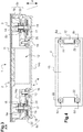
Les
L'interface 1 comporte une partie mobile 2 comprenant une surface tactile capacitive 3, une partie fixe 4 destinée à être fixée au véhicule automobile, au moins un élément amortisseur 5a, 5b, 5c, 5d interposé entre la partie mobile 2 et la partie fixe 4 pour relier la partie mobile 2 à la partie fixe 4 et au moins un capteur capacitif d'appui 6a, 6b, 6c, 6d configuré pour mesurer un paramètre représentatif d'une force d'appui exercée sur la surface tactile capacitive 3. Par interposé, on entend que la partie mobile 2 et la partie fixe 4 ne sont pas directement en contact, mais sont reliés seulement via un ou plusieurs éléments amortisseurs 5a, 5b, 5c, 5d.The
La surface tactile capacitive 3 comprend au moins un capteur capacitif 7 et une plaque frontale 8, telle qu'une plaque de verre ou de plastique, assurant la rigidité de la surface tactile capacitive 3. La plaque frontale 8 est agencée sur le au moins un capteur capacitif 7 et fait face à l'utilisateur une fois montée dans l'habitacle. La plaque frontale 8 peut être plane ou courbe et peut être au moins partiellement transparente et/ou au moins partiellement opaque de manière à cacher les éléments disposés derrière.The capacitive
Le capteur capacitif 7 permet de détecter une variation de capacité au niveau de la surface de la plaque frontale 8. Le capteur capacitif 7 peut par exemple détecter un contact ou un déplacement d'un doigt d'un utilisateur. Le capteur capacitif 7 permet également de déterminer les coordonnées spatiales du contact.The
Selon un premier exemple, l'interface est de type « tableau de commande » (aussi appelé « Control Panel » en anglais). La plaque frontale 8 est opaque et la partie mobile 2 comporte une ou plusieurs capteurs capacitifs 7 agencés à distance les uns des autres, formant une ou plusieurs zones de contact, reproduisant par exemple des touches de clavier ou des curseurs (« sliders » en anglais).According to a first example, the interface is of type "control panel" (also called "Control Panel" in English). The
Selon un deuxième exemple, l'interface est de type « pavé tactile » (aussi appelé « TouchPad » en anglais). La plaque frontale 8 est opaque et la partie mobile 2 comporte un capteur capacitif 7 de type dalle tactile capacitive, par exemple notamment apte à faire de la reconnaissance d'écriture.In a second example, the interface is of the "touchpad" type (also called "TouchPad" in English). The
Selon un troisième exemple, l'interface 1 est de type « écran tactile ». Dans ce cas, la partie mobile 2 comporte un écran d'affichage 9 agencé à l'arrière du capteur capacitif 7 de type dalle tactile capacitive, la surface tactile capacitive 3 étant au moins partiellement transparente.In a third example, the
Le capteur capacitif 7 est fixé à la plaque frontale 8 par exemple par une colle optique (appelée « optical bounding » en anglais). Le capteur capacitif 7 est par exemple formé d'un réseau d'électrodes s'étendant sur tout ou partie de la surface arrière de la plaque frontale 8. Les électrodes sont par exemple réalisées en ITO (oxyde indium - étain) qui permettent au capteur capacitif 7 d'être transparent.The
L'écran d'affichage 9, tel qu'un écran TFT (« Thin-Film transistor » en anglais) ou un écran LED ou un écran LCD peut être configuré pour afficher des informations associées à la manipulation de l'interface 1. L'écran 9 est disposé sous le capteur capacitif 7 de manière à former un écran tactile 10. L'écran d'affichage 9 peut être fixé au capteur capacitif 7 par une colle optique. Le capteur capacitif 7, la colle optique et la plaque frontale 8 sont au moins partiellement transparents pour permettre la visualisation des images affichées par l'écran 9.The
Outre l'écran tactile 10, la partie mobile 2 comporte un support 11 de la surface tactile capacitive 3, auquel est ici également fixé l'écran d'affichage 9 et contre lequel le au moins un élément amortisseur 5a, 5b, 5c, 5d vient en butée. La dimension de la plaque frontale 8 est par exemple supérieure à celle du capteur capacitif 7. Le support 11, par exemple en forme de cadre et par exemple métallique, peut ainsi être fixé à l'arrière de la plaque frontale 8, au niveau d'une surface opaque 8a laissée libre de la plaque frontale 8 autour du capteur capacitif 7.In addition to the
L'interface 1 peut aussi comporter au moins un actionneur vibratoire 12 configuré pour faire vibrer la partie mobile 2 en réponse à un contact, un déplacement ou un appui exercé sur la surface tactile capacitive 3 afin de fournir un retour haptique à l'utilisateur notamment pour l'informer de la prise en compte de sa commande.The
L'actionneur vibratoire 12 est par exemple de type piézoélectrique ou électromagnétique. Il repose par exemple sur une technologie similaire à celle du Haut-Parleur (en anglais : « Voice-Coil»). L'actionneur vibratoire 12 est par exemple monté « suspendu » par opposition à un montage « rattaché » dans lequel l'actionneur vibratoire 12 aurait été également solidaire de la partie fixe 4. L'interface 1 comporte par exemple un unique actionneur vibratoire 12 par exemple fixé au support 11, en périphérie de l'écran d'affichage 9. La vibration générée par l'actionneur vibratoire 12 peut être dirigée dans le plan de la surface tactile capacitive 3 ou orthogonalement au plan ou encore dirigée selon une combinaison de deux ou trois directions.The
La partie fixe 4 comporte une carte électronique 13, un châssis 14a et un socle 14b dont le fond permet de refermer l'interface 1. La carte électronique 13, par exemple de type PCB en anglais pour « Printed Circuit Board », porte notamment des circuits électriques de gestion de l'écran d'affichage 9 et de la surface tactile capacitive 3. Le châssis 14b présente par exemple une forme de cadre, le châssis 14a et le socle 14b s'assemblant par exemple au moyen de vis 15, par exemple au nombre de quatre, pour supporter et maintenir la carte électronique 13 par exemple en la prenant en sandwich.The
L'élément amortisseur 5a, 5b, 5c, 5d qui relie la partie mobile 2 de l'interface 1 à la partie fixe 4 comporte au moins un élément élastique, tel qu'un plot élastique, silicone ou caoutchouc travaillant en compression. L'élément élastique est par exemple d'une seule pièce et présente par exemple une forme générale sensiblement cylindrique présentant un orifice axial pour le passage d'un organe de fixation 17 de la partie mobile 2. L'interface 1 comporte par exemple quatre éléments amortisseurs 5a, 5b, 5c, 5d de type «silentblock ®».The damping
L'organe amortisseur 5a, 5b, 5c, 5d permet d'une part, d'amortir les vibrations de la partie mobile 2 générées par l'actionneur vibratoire 12 et d'autre part, de limiter le déplacement de la partie mobile 2 vers la partie fixe 4 lorsqu'un appui est exercé sur la surface tactile capacitive 3.The damping
L'élément élastique présente par exemple un dégagement annulaire central permettant à l'élément élastique d'être retenu dans un orifice respectif du châssis 14a. Les orifices du châssis 14a sont par exemple disposés aux quatre coins du châssis 14a. Les éléments élastiques peuvent être insérés dans les orifices du châssis 14a par déformation ou peuvent être surmoulés dans un orifice respectif.The elastic element has for example a central annular clearance allowing the elastic element to be retained in a respective hole of the
L'organe de fixation 17 est par exemple une vis ayant une tige surmontée d'une tête. L'extrémité de la tige est par exemple filetée pour être vissée dans le support 11 de la partie mobile 2.The fixing
Le au moins un capteur capacitif d'appui 6a, 6b, 6c, 6d comporte une électrode mobile 16 portée par la partie mobile 2 et une électrode fixe 22 portée par la partie fixe 4, l'électrode fixe 22 étant agencée en regard de l'électrode mobile 16 pour mesurer une distance « d » entre la partie mobile 2 et la partie fixe 4 dans une direction perpendiculaire à la surface tactile capacitive 3, représentative d'une force d'appui exercée sur la surface tactile capacitive 3 (
L'électrode fixe 22 et l'électrode mobile 16 sont des surfaces métalliques conductrices, par exemple en cuivre.The fixed
L'électrode fixe 22 est portée par la partie fixe 4, par exemple par la carte électronique 13. Elle est par exemple imprimée sur la carte électronique 13 comme les pistes électriques des circuits de la carte 13 (
L'électrode mobile 16 est portée par la partie mobile de sorte qu'un appui exercé sur la surface tactile capacitive 3 éloigne l'électrode mobile 16 de l'électrode fixe 22. Par exemple, l'électrode mobile 16 est portée par l'organe de fixation 17 de la partie mobile 2 traversant l'élément amortisseur 5a, 5b, 5c, 5d et la carte électronique 13.The moving
Avec cette configuration, la distance « d » augmente quand l'effort augmente. Cette configuration permet d'augmenter la précision de mesure des capteurs capacitifs d'appui 6a, 6b, 6c, 6d notamment pour les faibles valeurs d'efforts. En effet, les capteurs capacitifs d'appui 6a, 6b, 6c, 6d sont plus précis pour les distances « d » faibles.With this configuration, the distance "d" increases as the effort increases. This configuration makes it possible to increase the measurement accuracy of the
En outre, en position de repos, lorsqu'aucun appui n'est exercé sur la surface tactile capacitive 3, l'électrode mobile 27 et l'électrode fixe 22 sont en contact (
L'électrode fixe 22 du capteur capacitif d'appui 6a, 6b, 6c, 6d est par exemple portée par une face arrière de la carte électronique 13 portant les circuits électriques notamment pour la gestion de la surface tactile capacitive 3, en face avant (
Le contact n'est pas un contact direct entre parties métalliques. Pour éviter d'éventuels courts-circuits, l'une au moins des deux électrodes, mobile ou fixe, comporte par exemple une couche de vernis recouvrant les parties conductrices de l'électrode. L'électrode fixe 22 portée par la carte électronique 13 est par exemple recouverte du vernis, généralement coloré, de la carte électronique 13 permettant également de protéger les pistes de l'oxydation.Contact is not direct contact between metal parts. To avoid possible short circuits, at least one of the two electrodes, mobile or fixed, comprises for example a layer of varnish covering the conductive parts of the electrode. The fixed
Le fait que l'électrode fixe 22 soit portée par la carte électronique 13 de la partie fixe 4 et que l'électrode mobile 16 soit portée par l'organe de fixation 17 de la partie mobile 2 traversant l'élément amortisseur 5a, 5b, 5c, 5d et la carte électronique 13 permet que les électrodes fixe 22 et mobile 16 du au moins un capteur capacitif d'appui 6a, 6b, 6c, 6d puissent être au moins partiellement agencées sous l'élément amortisseur 5a, 5b, 5c, 5d, c'est-à-dire à l'arrière de ce dernier en considérant que l'avant est le côté de la plaque frontale 8. Le capteur capacitif d'appui 6a, 6b, 6c, 6d est ainsi disposé à l'emplacement où le déplacement de la partie mobile 2 par rapport à la partie fixe 4 est le plus important, dans l'axe de l'élément amortisseur 5a, 5b, 5c, 5d, ce qui permet d'optimiser la sensibilité du capteur capacitif d'appui 6a, 6b, 6c, 6d.The fact that the fixed
Plus précisément, l'électrode fixe 22 et l'électrode mobile 16 du au moins un capteur capacitif d'appui 6a, 6b, 6c, 6d peuvent entourer la tige de l'organe de fixation 17.More precisely, the fixed
Pour cela, l'électrode fixe 22 et l'électrode mobile 16 présentent par exemple des formes annulaires, par exemple sensiblement de mêmes dimensions. L'électrode mobile 16 est par exemple une rondelle métallique, la surface du disque métallique étant agencée parallèlement et en regard de la surface de l'électrode fixe 22.For this, the fixed
L'interface 1 comporte par exemple autant de capteurs capacitifs d'appui 6a, 6b, 6c, 6d que d'éléments amortisseurs 5a, 5b, 5c, 5d, par exemple quatre, agencés par exemple dans chaque coin de l'interface 1 de forme générale parallélépipédique (
La partie mobile 2 peut comporter au moins une entretoise, entourant la tige de l'organe de fixation 17, formant une butée pour le serrage de l'organe de fixation 17.The
Dans ce premier exemple de réalisation, la partie mobile 2 comporte deux entretoises métalliques 18, 19 montées en série.In this first exemplary embodiment, the
Une première entretoise métallique 18 cylindrique s'étend le long de l'élément amortisseur 5a, 5b, 5c, 5d. Cette première entretoise 18 permet notamment de pré-contraindre l'élément amortisseur 5a, 5b, 5c, 5d en compression pour garantir un amortissement de la partie mobile 2.A first
Une deuxième entretoise métallique 19 cylindrique s'étend entre la tête de l'organe de fixation 17 et la première entretoise métallique 18 le long de la tige de l'organe de fixation 17. La deuxième entretoise métallique 19 est par exemple formée d'une seule pièce avec l'électrode mobile 16.A second
La première entretoise métallique 18 vient en butée contre le support 11. La deuxième entretoise métallique 19 vient en butée contre la première entretoise 18. L'électrode mobile 16 vient en butée contre la tête de l'organe de fixation 17. Les entretoises 18, 19 forment ainsi une butée pour le serrage de l'organe de fixation 17 dans le support 11 au moment de l'assemblage de l'interface 1.The
Comme on le verra plus loin, d'autres réalisations sont également envisageables pour la au moins une entretoise.As will be seen below, other embodiments are also possible for the at least one spacer.
L'interface 1 peut comporter au moins un conducteur flexible 20 agencé entre la première entretoise métallique 18 et la carte électronique 13. Le conducteur flexible 20 raccorde électriquement l'entretoise métallique 18, et donc ici l'électrode mobile 16, à des pistes électriques de la carte électronique 13, qui sont ici raccordées à la masse électrique de la carte électronique 13. Il y a par exemple un conducteur flexible 20 pour chaque capteur capacitif d'appui 6a, 6b, 6c, 6d, donc quatre au total dans l'exemple.The
Dans l'exemple illustré sur les
La mesure de capacité des capteurs capacitifs d'appui 6a, 6b, 6c, 6d permettant d'accéder à la distance séparant la partie mobile 2 de la partie fixe 4 est réalisée entre l'électrode fixe 22 portée par la carte électronique 13 et l'électrode mobile 16 ici reliée à la masse. Ce mode est appelé « self capacitance» en anglais. Dans ce mode, seule l'électrode fixe 22 est excitée et la mesure est réalisée vis-à-vis de l'électrode mobile 16 reliée à la masse, sur cette même électrode fixe 22. Ce mode permet de simplifier l'architecture mécanique car la mise à la masse de l'électrode mobile 16 et du support 11 peut être réalisée simplement par les mêmes éléments : les entretoises métalliques 18, 19 et le conducteur flexible 20. De plus, une seule borne du circuit est utilisée par capteur capacitif d'appui, à la fois pour l'excitation et la mesure.The capacity measurement of the
Une unité de traitement comportant un ou plusieurs microcontrôleurs ou ordinateurs ou processeurs, ayant des mémoires et programmes adaptés peut être reliée aux capteurs capacitifs d'appui 6a, 6b, 6c, 6d et à l'écran tactile 10. C'est par exemple l'ordinateur de bord du véhicule automobile.A processing unit comprising one or more microcontrollers or computers or processors having suitable memories and programs can be connected to the
En fonctionnement, lors d'un appui avec effort sur la plaque frontale 8, la partie mobile 2 se déplace d'une distance « d » par rapport à la partie fixe 4, éloignant l'électrode mobile 16 de l'électrode fixe 22 portée par la carte électronique 13 et comprimant partiellement l'élément amortisseur 5a, 5b, 5c, 5d.In operation, during a support with force on the
Le capteur capacitif d'appui 6a, 6b, 6c, 6d détecte le déplacement de la partie mobile 2 vers la partie fixe 4, représentatif d'une force d'appui. La mesure de la distance « d » et la valeur calibrée de la suspension permettent d'en déduire la valeur de l'effort appliqué.The
La mesure de la force d'appui peut permettre de commander au moins une fonction de l'interface 1 par exemple uniquement lorsqu'une force d'appui exercée sur l'écran tactile 3 est supérieure à un seuil. La fonction de l'interface 1 peut être commandée relativement à l'intensité de la force d'appui exercée sur l'écran tactile 3. La mesure de la force d'appui exercée sur l'écran tactile 3 peut également permettre de contrôler au moins un paramètre de la vibration générée par l'actionneur vibratoire 12, relativement à l'intensité de l'effort d'appui exercé sur l'écran tactile 3.The measurement of the support force can make it possible to control at least one function of the
Cette architecture permet en plus de simplifier le montage de l'interface 1 qui peut être réalisé interface 1 retournée, par empilement de pièces, la plaque frontale 8 étant posée à plat sur un support de montage, le procédé de montage de l'interface 100 comportant les étapes suivantes (
On assemble les éléments d'une partie mobile 2 qui comporte un support 11, par exemple un écran tactile 10 et éventuellement un actionneur vibratoire 12, l'écran tactile 10 étant obtenu par collage d'une plaque frontale 8, d'un capteur capacitif 7 et d'un écran d'affichage 9.The elements of a
La plaque frontale 8 de la partie mobile 2 et posée à plat sur le support de montage (étape 101).The
Le châssis 14a pourvu d'éléments amortisseurs 5a, 5b, 5c, 5d (préalablement insérés ou surmoulés dans un orifice respectif du châssis 14a) est posé au-dessus du support 11 de la partie mobile 2 retournée, en alignant un orifice axial de l'élément amortisseur 5a, 5b, 5c, 5d dans l'axe d'un orifice du support 11 (étape 102). Une mousse peut être interposée entre l'extrémité périphérique du support 11 et l'extrémité périphérique du châssis 14a pour éviter l'entrée de poussières dans l'interface 1.The
On monte par exemple quatre électrodes mobiles 16 sur la face arrière de la carte électronique 13 en insérant les deuxièmes entretoises 19 dans des trous correspondants de la carte électronique 13.For example, four
Puis, on pose la carte électronique 13 pourvue d'électrodes mobiles 16, au-dessus du châssis 14a en alignant le trou de la carte électronique 13 dans l'axe de l'orifice du support 11 (étape 103).Then, we put the
L'alignement des trous de la carte électronique 13 et des orifices des éléments amortisseurs 5a, 5b, 5c, 5d peut être réalisé par faisceau laser ou par pré-maintien mécanique.The alignment of the holes of the
Puis, on serre les quatre organes de fixation 17 traversant l'élément amortisseur 5a, 5b, 5c, 5d et la carte électronique 13, dans le support 11 (étape 104). L'assemblage du sous-ensemble est terminé lorsque la tête de l'organe de fixation 17 vient en butée contre l'électrode mobile 16, la deuxième entretoise métallique 19 étant en butée contre la première entretoise métallique 18, elle-même en butée contre le support 11.Then, we tighten the four
On monte alors le socle 14b sur ce sous-ensemble et on serre quatre autres vis 15 permettant d'assembler le socle 14b au châssis 14a, à travers la carte électronique 13.The
L'interface 1 à surface tactile capacitive obtenue, apte à mesurer une force d'appui exercée sur la surface tactile capacitive 3, peut ainsi être réalisée de façon simple et donc de manière industrielle.The
La
Dans cet exemple, la partie mobile 2 comporte une seule entretoise 25 métallique.In this example, the
L'entretoise 25 cylindrique s'étend le long de la tige de l'organe de fixation 17 entre le support 11 et la tête de l'organe de fixation 17. Elle est formée d'une seule pièce avec l'électrode mobile Tx. L'entretoise 25 en butée contre le support 11 forme ainsi une butée pour le serrage de l'organe de fixation 17 dans le support 11 au moment de l'assemblage de l'interface 1.The
Dans cet exemple également, l'interface 1 comporte un conducteur flexible 24 agencé entre l'entretoise 25 métallique et la carte électronique 13 pour raccorder l'entretoise 25 à des pistes électriques de la carte électronique 13. Le conducteur flexible 24 comporte un fil électrique par exemple soudé sur une piste électrique de la carte électronique 13 d'une part et raccordé à une cosse métallique agencée entre la tête de l'organe de fixation 17 et l'électrode Tx d'autre part. Dans cet exemple, le conducteur flexible 24 raccorde électriquement l'entretoise métallique 25, et donc l'électrode mobile Tx, à la masse électrique de la carte électronique 13.In this example also, the
La
La partie mobile 2 comporte par exemple une seule entretoise 26 métallique, s'étendant le long de la tige de l'organe de fixation 17 entre le support 11 et la tête de l'organe de fixation 17. L'entretoise 26 en butée contre le support 11 forme ainsi une butée pour le serrage de l'organe de fixation 17 dans le support 11 au moment de l'assemblage de l'interface 1.The
L'électrode mobile 27 est distincte de l'entretoise 26. C'est par exemple une rondelle métallique dont l'ouverture 29 présente une forme adaptée pour permettre son montage autour de l'entretoise 26 avec un jeu radial (
L'ouverture 29 est par exemple ondulée radialement de manière à produire une pression dirigée vers l'organe de fixation 17.The
Les flancs 28 de l'ouverture 29 peuvent en outre être inclinés par rapport à l'axe de l'organe de fixation 17, l'ouverture 29 étant plus large côté tête de l'organe de fixation 17, pour éviter à l'électrode mobile 27 de glisser le long de l'entretoise 26 une fois montée.The
Au montage, après avoir posé la carte électronique 13 au-dessus du châssis 14a, on pousse l'électrode mobile 27 le long de l'entretoise 26 jusqu'à ce que l'électrode mobile 27 vienne au contact de la carte électronique 13, puis on serre l'organe de fixation 17 dans le support 11.On assembly, after placing the
Ainsi, quelque soit les tolérances mécaniques du système, le jeu entre l'électrode mobile 27 et l'électrode fixe 22 est toujours nul en position de repos. Le montage est ainsi facilité et la sensibilité capacitive est ainsi augmentée, ce qui permet de diminuer les dimensions des électrodes.Thus, whatever the mechanical tolerances of the system, the clearance between the
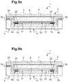
Les
Dans cet exemple de réalisation, le support 30 de la partie mobile 2 présente un élément de support arrière s'étendant au dos d'un cadre du support 30 auquel est fixé la plaque frontale 8. L'élément de support arrière s'étend vers la partie fixe et porte une électrode mobile 16.In this embodiment, the
Le châssis 14 de la partie fixe 4 comporte au moins un pied 31 portant la carte électronique 13 et traversant l'élément de support arrière du support 30.The
L'élément de support arrière du support 30 est ainsi agencé entre la carte électronique 13 et le châssis 14. Un appui sur la surface tactile capacitive 3 éloigne les électrodes du capteur capacitif d'appui 6a, 6b.The rear support element of the
Dans la position de repos, lorsqu'aucun appui n'est exercé sur la surface tactile capacitive 3, l'électrode mobile 16 et l'électrode fixe 22 sont en contact (
Lorsqu'un utilisateur appuie sur la surface tactile capacitive 3, un écart apparait entre les électrodes 16, 22, l'écart augmentant avec l'augmentation de l'effort (
En plus du coût réduit du fait de l'utilisation d'une seule carte électronique 13 commune pour l'écran 9 et les capteurs d'appui 6a, 6b, cette configuration permet d'augmenter la précision de mesure notamment pour les faibles valeurs d'efforts. En effet, le capteur d'appui capacitif est plus précis lorsqu'il est situé proche de la cible, c'est-à-dire pour les distances d faibles. En outre, les électrodes 16, 22 en contact au repos permet de s'affranchir du besoin d'un jeu minimal de repos entre les électrodes et facilite le montage.In addition to the reduced cost due to the use of a single common
Claims (15)
Applications Claiming Priority (1)
| Application Number | Priority Date | Filing Date | Title |
|---|---|---|---|
| FR1663306A FR3061320B1 (en) | 2016-12-23 | 2016-12-23 | INTERFACE FOR MOTOR VEHICLE AND METHOD OF MOUNTING |
Publications (2)
| Publication Number | Publication Date |
|---|---|
| EP3340022A1 true EP3340022A1 (en) | 2018-06-27 |
| EP3340022B1 EP3340022B1 (en) | 2020-03-25 |
Family
ID=58401800
Family Applications (1)
| Application Number | Title | Priority Date | Filing Date |
|---|---|---|---|
| EP17210509.0A Active EP3340022B1 (en) | 2016-12-23 | 2017-12-22 | Interface for motor vehicle and mounting method |
Country Status (2)
| Country | Link |
|---|---|
| EP (1) | EP3340022B1 (en) |
| FR (1) | FR3061320B1 (en) |
Cited By (1)
| Publication number | Priority date | Publication date | Assignee | Title |
|---|---|---|---|---|
| WO2020157175A1 (en) | 2019-01-31 | 2020-08-06 | Valeo Comfort And Driving Assistance | Method for generating a haptic feedback for an interface, and associated interface |
Citations (6)
| Publication number | Priority date | Publication date | Assignee | Title |
|---|---|---|---|---|
| FR2459462A1 (en) * | 1979-06-18 | 1981-01-09 | Testut Aequitas | Diaphragm dynamometer for measurement of applied force - has axial guide assembly with capacitive sensor on load shaft |
| EP0476309A2 (en) * | 1990-09-19 | 1992-03-25 | Johnson Service Company | Capacitance elastomeric low pressure sensor |
| EP1059604A2 (en) * | 1999-06-08 | 2000-12-13 | Newcom Inc. | Coordinate input device allowing input by finger, pen or the like |
| FR2819586A1 (en) * | 2001-01-17 | 2002-07-19 | Siemens Ag | Force sensor, especially for motor vehicle brake-by-wire systems, requiring accurate brake force measurement in a harsh environment with large temperature fluctuations, is based on a capacitive sensor arrangement |
| WO2008065205A1 (en) * | 2006-12-01 | 2008-06-05 | Thales | Data entry device and method for implementing the device |
| WO2016135425A1 (en) * | 2015-02-27 | 2016-09-01 | Dav | Haptic feedback device and method for a motor vehicle |
-
2016
- 2016-12-23 FR FR1663306A patent/FR3061320B1/en active Active
-
2017
- 2017-12-22 EP EP17210509.0A patent/EP3340022B1/en active Active
Patent Citations (6)
| Publication number | Priority date | Publication date | Assignee | Title |
|---|---|---|---|---|
| FR2459462A1 (en) * | 1979-06-18 | 1981-01-09 | Testut Aequitas | Diaphragm dynamometer for measurement of applied force - has axial guide assembly with capacitive sensor on load shaft |
| EP0476309A2 (en) * | 1990-09-19 | 1992-03-25 | Johnson Service Company | Capacitance elastomeric low pressure sensor |
| EP1059604A2 (en) * | 1999-06-08 | 2000-12-13 | Newcom Inc. | Coordinate input device allowing input by finger, pen or the like |
| FR2819586A1 (en) * | 2001-01-17 | 2002-07-19 | Siemens Ag | Force sensor, especially for motor vehicle brake-by-wire systems, requiring accurate brake force measurement in a harsh environment with large temperature fluctuations, is based on a capacitive sensor arrangement |
| WO2008065205A1 (en) * | 2006-12-01 | 2008-06-05 | Thales | Data entry device and method for implementing the device |
| WO2016135425A1 (en) * | 2015-02-27 | 2016-09-01 | Dav | Haptic feedback device and method for a motor vehicle |
Cited By (2)
| Publication number | Priority date | Publication date | Assignee | Title |
|---|---|---|---|---|
| WO2020157175A1 (en) | 2019-01-31 | 2020-08-06 | Valeo Comfort And Driving Assistance | Method for generating a haptic feedback for an interface, and associated interface |
| FR3092415A1 (en) | 2019-01-31 | 2020-08-07 | Valeo Comfort And Driving Assistance | Method of generating sensitive feedback for an interface and associated interface |
Also Published As
| Publication number | Publication date |
|---|---|
| EP3340022B1 (en) | 2020-03-25 |
| FR3061320B1 (en) | 2019-05-31 |
| FR3061320A1 (en) | 2018-06-29 |
Similar Documents
| Publication | Publication Date | Title |
|---|---|---|
| EP3394710A1 (en) | Control interface for a motor vehicle | |
| WO2017017268A1 (en) | Damping device, and haptic feedback method and device for motor vehicle | |
| WO2016135425A1 (en) | Haptic feedback device and method for a motor vehicle | |
| WO2018060383A1 (en) | Interface for motor vehicle and control method | |
| EP3559790B1 (en) | Interface for a motor vehicle and mounting method | |
| EP3340022B1 (en) | Interface for motor vehicle and mounting method | |
| EP3221762B1 (en) | Display device for motor vehicle | |
| WO2017108898A1 (en) | Control interface for automotive vehicle | |
| FR3056860B1 (en) | CAPACITIVE CONTROL INTERFACE FOR MOTOR VEHICLE | |
| EP3519234B1 (en) | Interface for motor vehicle and method for generating haptic feedback | |
| EP3083315B1 (en) | Display device intented notably for a motor vehicle | |
| EP3519232B1 (en) | Interface for motor vehicle and control method | |
| FR3056475A1 (en) | INTERFACE FOR MOTOR VEHICLE | |
| FR3104079A1 (en) | Motor vehicle interface and mounting method | |
| FR3056468A1 (en) | INTERFACE FOR MOTOR VEHICLE | |
| EP3519230B1 (en) | Interface for a motor vehicle | |
| EP3662351B1 (en) | Haptic feedback interface for a motor vehicle | |
| EP3159774B1 (en) | Device with capacitive interface for motor vehicle | |
| WO2017211835A1 (en) | Control module and method for motor vehicle | |
| FR3098618A1 (en) | INCREASED ROBUSTNESS HAPTICAL FEEDBACK CONTROL INTERFACE | |
| EP2180396A1 (en) | Control device with haptic feedback |
Legal Events
| Date | Code | Title | Description |
|---|---|---|---|
| PUAI | Public reference made under article 153(3) epc to a published international application that has entered the european phase |
Free format text: ORIGINAL CODE: 0009012 |
|
| STAA | Information on the status of an ep patent application or granted ep patent |
Free format text: STATUS: THE APPLICATION HAS BEEN PUBLISHED |
|
| AK | Designated contracting states |
Kind code of ref document: A1 Designated state(s): AL AT BE BG CH CY CZ DE DK EE ES FI FR GB GR HR HU IE IS IT LI LT LU LV MC MK MT NL NO PL PT RO RS SE SI SK SM TR |
|
| AX | Request for extension of the european patent |
Extension state: BA ME |
|
| STAA | Information on the status of an ep patent application or granted ep patent |
Free format text: STATUS: REQUEST FOR EXAMINATION WAS MADE |
|
| 17P | Request for examination filed |
Effective date: 20181221 |
|
| RBV | Designated contracting states (corrected) |
Designated state(s): AL AT BE BG CH CY CZ DE DK EE ES FI FR GB GR HR HU IE IS IT LI LT LU LV MC MK MT NL NO PL PT RO RS SE SI SK SM TR |
|
| STAA | Information on the status of an ep patent application or granted ep patent |
Free format text: STATUS: EXAMINATION IS IN PROGRESS |
|
| 17Q | First examination report despatched |
Effective date: 20190322 |
|
| GRAP | Despatch of communication of intention to grant a patent |
Free format text: ORIGINAL CODE: EPIDOSNIGR1 |
|
| STAA | Information on the status of an ep patent application or granted ep patent |
Free format text: STATUS: GRANT OF PATENT IS INTENDED |
|
| INTG | Intention to grant announced |
Effective date: 20191204 |
|
| GRAS | Grant fee paid |
Free format text: ORIGINAL CODE: EPIDOSNIGR3 |
|
| GRAA | (expected) grant |
Free format text: ORIGINAL CODE: 0009210 |
|
| STAA | Information on the status of an ep patent application or granted ep patent |
Free format text: STATUS: THE PATENT HAS BEEN GRANTED |
|
| AK | Designated contracting states |
Kind code of ref document: B1 Designated state(s): AL AT BE BG CH CY CZ DE DK EE ES FI FR GB GR HR HU IE IS IT LI LT LU LV MC MK MT NL NO PL PT RO RS SE SI SK SM TR |
|
| REG | Reference to a national code |
Ref country code: GB Ref legal event code: FG4D Free format text: NOT ENGLISH |
|
| REG | Reference to a national code |
Ref country code: AT Ref legal event code: REF Ref document number: 1249306 Country of ref document: AT Kind code of ref document: T Effective date: 20200415 Ref country code: IE Ref legal event code: FG4D Free format text: LANGUAGE OF EP DOCUMENT: FRENCH |
|
| REG | Reference to a national code |
Ref country code: DE Ref legal event code: R096 Ref document number: 602017013573 Country of ref document: DE |
|
| PG25 | Lapsed in a contracting state [announced via postgrant information from national office to epo] |
Ref country code: NO Free format text: LAPSE BECAUSE OF FAILURE TO SUBMIT A TRANSLATION OF THE DESCRIPTION OR TO PAY THE FEE WITHIN THE PRESCRIBED TIME-LIMIT Effective date: 20200625 Ref country code: RS Free format text: LAPSE BECAUSE OF FAILURE TO SUBMIT A TRANSLATION OF THE DESCRIPTION OR TO PAY THE FEE WITHIN THE PRESCRIBED TIME-LIMIT Effective date: 20200325 Ref country code: FI Free format text: LAPSE BECAUSE OF FAILURE TO SUBMIT A TRANSLATION OF THE DESCRIPTION OR TO PAY THE FEE WITHIN THE PRESCRIBED TIME-LIMIT Effective date: 20200325 |
|
| PG25 | Lapsed in a contracting state [announced via postgrant information from national office to epo] |
Ref country code: HR Free format text: LAPSE BECAUSE OF FAILURE TO SUBMIT A TRANSLATION OF THE DESCRIPTION OR TO PAY THE FEE WITHIN THE PRESCRIBED TIME-LIMIT Effective date: 20200325 Ref country code: GR Free format text: LAPSE BECAUSE OF FAILURE TO SUBMIT A TRANSLATION OF THE DESCRIPTION OR TO PAY THE FEE WITHIN THE PRESCRIBED TIME-LIMIT Effective date: 20200626 Ref country code: BG Free format text: LAPSE BECAUSE OF FAILURE TO SUBMIT A TRANSLATION OF THE DESCRIPTION OR TO PAY THE FEE WITHIN THE PRESCRIBED TIME-LIMIT Effective date: 20200625 Ref country code: SE Free format text: LAPSE BECAUSE OF FAILURE TO SUBMIT A TRANSLATION OF THE DESCRIPTION OR TO PAY THE FEE WITHIN THE PRESCRIBED TIME-LIMIT Effective date: 20200325 Ref country code: LV Free format text: LAPSE BECAUSE OF FAILURE TO SUBMIT A TRANSLATION OF THE DESCRIPTION OR TO PAY THE FEE WITHIN THE PRESCRIBED TIME-LIMIT Effective date: 20200325 |
|
| REG | Reference to a national code |
Ref country code: NL Ref legal event code: MP Effective date: 20200325 |
|
| REG | Reference to a national code |
Ref country code: LT Ref legal event code: MG4D |
|
| PG25 | Lapsed in a contracting state [announced via postgrant information from national office to epo] |
Ref country code: NL Free format text: LAPSE BECAUSE OF FAILURE TO SUBMIT A TRANSLATION OF THE DESCRIPTION OR TO PAY THE FEE WITHIN THE PRESCRIBED TIME-LIMIT Effective date: 20200325 |
|
| PG25 | Lapsed in a contracting state [announced via postgrant information from national office to epo] |
Ref country code: RO Free format text: LAPSE BECAUSE OF FAILURE TO SUBMIT A TRANSLATION OF THE DESCRIPTION OR TO PAY THE FEE WITHIN THE PRESCRIBED TIME-LIMIT Effective date: 20200325 Ref country code: EE Free format text: LAPSE BECAUSE OF FAILURE TO SUBMIT A TRANSLATION OF THE DESCRIPTION OR TO PAY THE FEE WITHIN THE PRESCRIBED TIME-LIMIT Effective date: 20200325 Ref country code: SM Free format text: LAPSE BECAUSE OF FAILURE TO SUBMIT A TRANSLATION OF THE DESCRIPTION OR TO PAY THE FEE WITHIN THE PRESCRIBED TIME-LIMIT Effective date: 20200325 Ref country code: CZ Free format text: LAPSE BECAUSE OF FAILURE TO SUBMIT A TRANSLATION OF THE DESCRIPTION OR TO PAY THE FEE WITHIN THE PRESCRIBED TIME-LIMIT Effective date: 20200325 Ref country code: LT Free format text: LAPSE BECAUSE OF FAILURE TO SUBMIT A TRANSLATION OF THE DESCRIPTION OR TO PAY THE FEE WITHIN THE PRESCRIBED TIME-LIMIT Effective date: 20200325 Ref country code: PT Free format text: LAPSE BECAUSE OF FAILURE TO SUBMIT A TRANSLATION OF THE DESCRIPTION OR TO PAY THE FEE WITHIN THE PRESCRIBED TIME-LIMIT Effective date: 20200818 Ref country code: SK Free format text: LAPSE BECAUSE OF FAILURE TO SUBMIT A TRANSLATION OF THE DESCRIPTION OR TO PAY THE FEE WITHIN THE PRESCRIBED TIME-LIMIT Effective date: 20200325 Ref country code: IS Free format text: LAPSE BECAUSE OF FAILURE TO SUBMIT A TRANSLATION OF THE DESCRIPTION OR TO PAY THE FEE WITHIN THE PRESCRIBED TIME-LIMIT Effective date: 20200725 |
|
| REG | Reference to a national code |
Ref country code: AT Ref legal event code: MK05 Ref document number: 1249306 Country of ref document: AT Kind code of ref document: T Effective date: 20200325 |
|
| REG | Reference to a national code |
Ref country code: DE Ref legal event code: R097 Ref document number: 602017013573 Country of ref document: DE |
|
| PG25 | Lapsed in a contracting state [announced via postgrant information from national office to epo] |
Ref country code: IT Free format text: LAPSE BECAUSE OF FAILURE TO SUBMIT A TRANSLATION OF THE DESCRIPTION OR TO PAY THE FEE WITHIN THE PRESCRIBED TIME-LIMIT Effective date: 20200325 Ref country code: AT Free format text: LAPSE BECAUSE OF FAILURE TO SUBMIT A TRANSLATION OF THE DESCRIPTION OR TO PAY THE FEE WITHIN THE PRESCRIBED TIME-LIMIT Effective date: 20200325 Ref country code: DK Free format text: LAPSE BECAUSE OF FAILURE TO SUBMIT A TRANSLATION OF THE DESCRIPTION OR TO PAY THE FEE WITHIN THE PRESCRIBED TIME-LIMIT Effective date: 20200325 Ref country code: ES Free format text: LAPSE BECAUSE OF FAILURE TO SUBMIT A TRANSLATION OF THE DESCRIPTION OR TO PAY THE FEE WITHIN THE PRESCRIBED TIME-LIMIT Effective date: 20200325 |
|
| PLBE | No opposition filed within time limit |
Free format text: ORIGINAL CODE: 0009261 |
|
| STAA | Information on the status of an ep patent application or granted ep patent |
Free format text: STATUS: NO OPPOSITION FILED WITHIN TIME LIMIT |
|
| PG25 | Lapsed in a contracting state [announced via postgrant information from national office to epo] |
Ref country code: PL Free format text: LAPSE BECAUSE OF FAILURE TO SUBMIT A TRANSLATION OF THE DESCRIPTION OR TO PAY THE FEE WITHIN THE PRESCRIBED TIME-LIMIT Effective date: 20200325 |
|
| 26N | No opposition filed |
Effective date: 20210112 |
|
| PG25 | Lapsed in a contracting state [announced via postgrant information from national office to epo] |
Ref country code: SI Free format text: LAPSE BECAUSE OF FAILURE TO SUBMIT A TRANSLATION OF THE DESCRIPTION OR TO PAY THE FEE WITHIN THE PRESCRIBED TIME-LIMIT Effective date: 20200325 |
|
| REG | Reference to a national code |
Ref country code: CH Ref legal event code: PL |
|
| PG25 | Lapsed in a contracting state [announced via postgrant information from national office to epo] |
Ref country code: MC Free format text: LAPSE BECAUSE OF FAILURE TO SUBMIT A TRANSLATION OF THE DESCRIPTION OR TO PAY THE FEE WITHIN THE PRESCRIBED TIME-LIMIT Effective date: 20200325 |
|
| REG | Reference to a national code |
Ref country code: BE Ref legal event code: MM Effective date: 20201231 |
|
| PG25 | Lapsed in a contracting state [announced via postgrant information from national office to epo] |
Ref country code: IE Free format text: LAPSE BECAUSE OF NON-PAYMENT OF DUE FEES Effective date: 20201222 Ref country code: LU Free format text: LAPSE BECAUSE OF NON-PAYMENT OF DUE FEES Effective date: 20201222 |
|
| PG25 | Lapsed in a contracting state [announced via postgrant information from national office to epo] |
Ref country code: LI Free format text: LAPSE BECAUSE OF NON-PAYMENT OF DUE FEES Effective date: 20201231 Ref country code: CH Free format text: LAPSE BECAUSE OF NON-PAYMENT OF DUE FEES Effective date: 20201231 |
|
| PG25 | Lapsed in a contracting state [announced via postgrant information from national office to epo] |
Ref country code: TR Free format text: LAPSE BECAUSE OF FAILURE TO SUBMIT A TRANSLATION OF THE DESCRIPTION OR TO PAY THE FEE WITHIN THE PRESCRIBED TIME-LIMIT Effective date: 20200325 Ref country code: MT Free format text: LAPSE BECAUSE OF FAILURE TO SUBMIT A TRANSLATION OF THE DESCRIPTION OR TO PAY THE FEE WITHIN THE PRESCRIBED TIME-LIMIT Effective date: 20200325 Ref country code: CY Free format text: LAPSE BECAUSE OF FAILURE TO SUBMIT A TRANSLATION OF THE DESCRIPTION OR TO PAY THE FEE WITHIN THE PRESCRIBED TIME-LIMIT Effective date: 20200325 |
|
| PG25 | Lapsed in a contracting state [announced via postgrant information from national office to epo] |
Ref country code: MK Free format text: LAPSE BECAUSE OF FAILURE TO SUBMIT A TRANSLATION OF THE DESCRIPTION OR TO PAY THE FEE WITHIN THE PRESCRIBED TIME-LIMIT Effective date: 20200325 Ref country code: AL Free format text: LAPSE BECAUSE OF FAILURE TO SUBMIT A TRANSLATION OF THE DESCRIPTION OR TO PAY THE FEE WITHIN THE PRESCRIBED TIME-LIMIT Effective date: 20200325 |
|
| PG25 | Lapsed in a contracting state [announced via postgrant information from national office to epo] |
Ref country code: BE Free format text: LAPSE BECAUSE OF NON-PAYMENT OF DUE FEES Effective date: 20201231 |
|
| GBPC | Gb: european patent ceased through non-payment of renewal fee |
Effective date: 20211222 |
|
| PG25 | Lapsed in a contracting state [announced via postgrant information from national office to epo] |
Ref country code: GB Free format text: LAPSE BECAUSE OF NON-PAYMENT OF DUE FEES Effective date: 20211222 |
|
| P01 | Opt-out of the competence of the unified patent court (upc) registered |
Effective date: 20230528 |
|
| PGFP | Annual fee paid to national office [announced via postgrant information from national office to epo] |
Ref country code: FR Payment date: 20231220 Year of fee payment: 7 Ref country code: DE Payment date: 20231208 Year of fee payment: 7 |