EP3339932B1 - Optical zoom with mobile pupil - Google Patents
Optical zoom with mobile pupil Download PDFInfo
- Publication number
- EP3339932B1 EP3339932B1 EP17207943.6A EP17207943A EP3339932B1 EP 3339932 B1 EP3339932 B1 EP 3339932B1 EP 17207943 A EP17207943 A EP 17207943A EP 3339932 B1 EP3339932 B1 EP 3339932B1
- Authority
- EP
- European Patent Office
- Prior art keywords
- pupil
- zoom
- group
- aperture
- movable
- Prior art date
- Legal status (The legal status is an assumption and is not a legal conclusion. Google has not performed a legal analysis and makes no representation as to the accuracy of the status listed.)
- Active
Links
- 210000001747 pupil Anatomy 0.000 title claims description 70
- 230000003287 optical effect Effects 0.000 title claims description 34
- 230000004075 alteration Effects 0.000 claims description 28
- 201000009310 astigmatism Diseases 0.000 claims description 8
- 206010073261 Ovarian theca cell tumour Diseases 0.000 claims description 2
- 208000001644 thecoma Diseases 0.000 claims description 2
- 238000006073 displacement reaction Methods 0.000 description 18
- 206010010071 Coma Diseases 0.000 description 8
- 230000008901 benefit Effects 0.000 description 3
- 238000004519 manufacturing process Methods 0.000 description 3
- 238000000034 method Methods 0.000 description 3
- 238000005457 optimization Methods 0.000 description 3
- 238000013461 design Methods 0.000 description 2
- 208000028333 fixed pupil Diseases 0.000 description 2
- 208000022749 pupil disease Diseases 0.000 description 2
- 229920000297 Rayon Polymers 0.000 description 1
- 230000001594 aberrant effect Effects 0.000 description 1
- 230000009471 action Effects 0.000 description 1
- 230000008859 change Effects 0.000 description 1
- 238000012937 correction Methods 0.000 description 1
- 230000000694 effects Effects 0.000 description 1
- 238000005286 illumination Methods 0.000 description 1
- 238000003384 imaging method Methods 0.000 description 1
- 239000000463 material Substances 0.000 description 1
- 239000002964 rayon Substances 0.000 description 1
- 230000009467 reduction Effects 0.000 description 1
- 230000004044 response Effects 0.000 description 1
- 238000007789 sealing Methods 0.000 description 1
- 238000012546 transfer Methods 0.000 description 1
- 238000013519 translation Methods 0.000 description 1
- 238000011144 upstream manufacturing Methods 0.000 description 1
Images


Classifications
-
- G—PHYSICS
- G02—OPTICS
- G02B—OPTICAL ELEMENTS, SYSTEMS OR APPARATUS
- G02B15/00—Optical objectives with means for varying the magnification
- G02B15/14—Optical objectives with means for varying the magnification by axial movement of one or more lenses or groups of lenses relative to the image plane for continuously varying the equivalent focal length of the objective
- G02B15/144—Optical objectives with means for varying the magnification by axial movement of one or more lenses or groups of lenses relative to the image plane for continuously varying the equivalent focal length of the objective having four groups only
- G02B15/1445—Optical objectives with means for varying the magnification by axial movement of one or more lenses or groups of lenses relative to the image plane for continuously varying the equivalent focal length of the objective having four groups only the first group being negative
- G02B15/144511—Optical objectives with means for varying the magnification by axial movement of one or more lenses or groups of lenses relative to the image plane for continuously varying the equivalent focal length of the objective having four groups only the first group being negative arranged -+-+
-
- G—PHYSICS
- G02—OPTICS
- G02B—OPTICAL ELEMENTS, SYSTEMS OR APPARATUS
- G02B15/00—Optical objectives with means for varying the magnification
- G02B15/14—Optical objectives with means for varying the magnification by axial movement of one or more lenses or groups of lenses relative to the image plane for continuously varying the equivalent focal length of the objective
- G02B15/16—Optical objectives with means for varying the magnification by axial movement of one or more lenses or groups of lenses relative to the image plane for continuously varying the equivalent focal length of the objective with interdependent non-linearly related movements between one lens or lens group, and another lens or lens group
- G02B15/177—Optical objectives with means for varying the magnification by axial movement of one or more lenses or groups of lenses relative to the image plane for continuously varying the equivalent focal length of the objective with interdependent non-linearly related movements between one lens or lens group, and another lens or lens group having a negative front lens or group of lenses
-
- G—PHYSICS
- G02—OPTICS
- G02B—OPTICAL ELEMENTS, SYSTEMS OR APPARATUS
- G02B27/00—Optical systems or apparatus not provided for by any of the groups G02B1/00 - G02B26/00, G02B30/00
- G02B27/0012—Optical design, e.g. procedures, algorithms, optimisation routines
-
- G—PHYSICS
- G02—OPTICS
- G02B—OPTICAL ELEMENTS, SYSTEMS OR APPARATUS
- G02B27/00—Optical systems or apparatus not provided for by any of the groups G02B1/00 - G02B26/00, G02B30/00
- G02B27/0025—Optical systems or apparatus not provided for by any of the groups G02B1/00 - G02B26/00, G02B30/00 for optical correction, e.g. distorsion, aberration
Definitions
- the field of invention is that of shooting objectives, and more specifically that of optical zooms.
- Optical zoom is understood to mean optics in which the field variation is performed optically and not electronically.
- the opening of the zoom which governs the amount of light received, is dictated by the diameter of the pupil.
- the pupil usually materialized by an iris of variable diameter, often has a fixed position and is then either between the third and the fourth element or inside the fourth element.
- the exit pupil thus occupies a fixed position, while the entrance pupil moves along the optical axis and has a variable diameter depending on the focal length of the zoom.
- the useful diameters of The lenses between the third element and the image plane remain constant while they vary for the lenses between the third element and the front of the zoom.
- Field aberrations such as coma, astigmatism or distortion depend on the position of the pupil so that it also constitutes a degree of freedom for zoom optimization.
- Zooms of this type operating over a wide range of focal lengths called “range” often have large diameter front optics that are both delicate to achieve, expensive and can weigh down and unbalance the zoom.
- the size of an optic depends on the size of the pupil and the distance of the pupil. When the pupil is distant, high fields lead to significant optical dimensions.
- the diameter of the front optics is governed by the aperture.
- ramping that is to say a vignetting of the beam on the axis at long focal lengths to try to minimize the diameter of the front optics.
- the diameter of the front optics depends mainly on the axial position of the objective entrance pupil and, of course, the field strength. From the above relationship, the pupil diameter, which is small in this configuration, has little influence.
- This publication shows that positioning a mobile pupil between the first two elements and allowing it to follow its own law of displacement makes it possible to control the diameters of the front and rear optics.
- This method ensures that the ratio of the diameters between the largest lens and the smallest lens of the system does not exceed a ratio of two.
- Such a system is also effective only for zooms having reasonable zoom ranges, because if it reduces the diameter of the front optics, it causes a significant increase in the diameters of the lenses of the second and third elements.
- the lens diameters of the intermediate groups may become larger than those of the first element.
- the second obstacle limiting the rays after the pupil is the skylight.
- Architectures with two moving diaphragms are described in the literature.
- the patent US 3,918,798 entitled “Zoom lens having two diaphragms” which describes an optical architecture of this type.
- the zoom according to the invention does not have these disadvantages. More precisely, the subject of the invention is an optical zoom lens as defined in independent claim 1.
- the position of the pupil is that which minimizes the most important field aberration at said focal length.
- the position of the pupil is the one that minimizes the coma and for the short focal lengths of the zoom, the position of the pupil is that which minimizes the astigmatism and / or the curvature of the field.
- the pupil being a metallic iris
- the movements and variations of this iris are ensured by first cam systems coupled with second cam systems actuating the movements of the moving optical zoom elements.
- the zoom according to the invention has four groups of lenses, called “elements” and noted successively from 1 to 4, the element 1 being located at the input of the zoom and the element 4 at the output closest to the focal plane .
- the element 1 of said zoom is fixed according to the focal length, the elements 2 and 3 are movable. These elements 2 and 3 are respectively convergent and divergent. They allow you to vary the focal length of the zoom while maintaining a still image.
- Element 4 is a convergent fixed element.
- the zoom comprises a mobile pupil materialized by an iris, the opening diameter of which can be varied by mechanical action.
- This iris can be located in element 2 of the zoom, between its element 2 and its element 3, in its element 3 or between its element 3 and its element 4.
- the diameter of this iris is adjusted according to the position that he occupies in the system. We can keep the opening of the system constant when the iris moves.
- the displacement of the pupil makes it possible to release an additional calculation parameter during the optimization of the optical combination, and goes in the direction of a better correction of the aberrations of the system, and therefore of a better quality of imaging, the field aberrations depend on the position of the pupil.
- the displacement of the iris To the displacement of the iris, one can associate the displacement and the variation of diameter of a skylight located upstream of the moving iris, and / or the displacement and the variation of diameter of a skylight situated downstream of this iris .
- This mobile skylight optimally controls vignetting so as to reduce transverse aberrations in the image plane and to control the loss of illumination between the center and the edge of the field.
- This control which depends on the focal length of the zoom can maintain the opening of the zoom by acting only on the field rays.
- the pupil can thus pass from one element to another or pass through an element during a variation of the focal length of the system. If it is mechanically difficult to move an iris on the other side of a group of lenses, it is however possible that during the displacement of the elements 2 and 3, a skylight which vignette the optical beam in the field is transforms in turn into a pupil delimiting the beam on the axis. By allowing such a pupil displacement from one element to another, the total travel distance of said pupil can be substantially increased.
- the first zoom Z1 includes a fixed pupil P F and the second zoom Z2 comprises a mobile pupil P M according to the invention.
- the focal length of the zooms varies between 15mm and 40mm and their aperture is F / 2.6.
- the zoom Z1 represented on the Figures 1 and 2 comprises a divergent fixed element 11, a convergent moving element 12, a diverging movable element 13 and a convergent fixed element 14.
- the pupil P F is fixed and located between the element 13 and the element 14.
- this zoom Z1 is represented in a configuration where the positions of the elements 12 and 13 make it possible to obtain a short focal length.
- this zoom Z1 is represented in a configuration where the positions of the elements 12 and 13 make it possible to obtain a long focal length.
- the front lenses of the element 11 are larger in diameter than the lenses on the back of the zoom. Moreover, the useful areas on these frontal lenses are maximum at short focal length as seen on the figure 1 , the useful areas being the surfaces covered by the light rays on each diopter.
- the zoom Z2 represented on the Figures 3 and 4 comprises a divergent fixed element 21, a convergent movable element 22, a diverging movable element 23 and a convergent fixed element 44.
- the pupil P M is mobile.
- this zoom Z2 is represented in a configuration where the positions of the elements 22 and 23 make it possible to obtain a short focal length.
- this zoom Z2 is represented in a configuration where the positions of the elements 22 and 23 make it possible to obtain a long focal length.
- This zoom Z2 has been calculated by taking as a starting point the zoom Z1 and has, unlike the latter, a mobile pupil P M with a variable diameter which is located inside the element 22.
- the pupil moves according to the same displacement law as that of the element 22.
- this zoom has been calculated on the basis of the same properties as that of the Z1 zoom with fixed pupil of Figures 1 and 2 that is, its focal length, aspect ratio, length, distortion, modulation transfer function, or "FTM" are the same or similar to those of the Z1 zoom.
- the displacement of the iris makes it possible to obtain an entrance pupil closer to the lenses constituting the element 1, in particular, in the case of a fixed iris.
- the entrance pupil of the zoom Z1 is 44mm from the first diopter, while the entrance pupil of the zoom Z2 is 36mm from the first diopter.
- both zooms have a large field.
- the diameter of the first lenses therefore depends essentially on the position of the entrance pupil.
- the first lens has a diameter of 87mm, while in the optical combination with moving iris zoom Z2, this diameter is reduced to 67mm.
- the mass of the zoom Z2 is also reduced by about 45% compared to that of Z1.
- the first zoom has a weight of about 700 grams while the second zoom has a weight of about 400 grams. This also makes it possible to reduce overall the cost of manufacturing the lenses.
- Moving the iris also moves the exit pupil of the system in the same direction of movement as the iris.
- the lenses of the rear group of the zoom Z2 have a larger diameter in the moving-iris solution, since the exit pupil is moved away from the image plane.
- the advantage of this solution is that the zoom configuration Z2 is closer to the telecentricity conditions, that is to say an exit pupil located at infinity. This configuration makes it possible to have effects on the detector that are independent of the field and thus guarantees better response homogeneities.
- Another advantage of the mobile-eye zoom configuration is that it allows for better optimization of the optical combination.
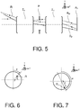
- optical system Figures 5, 6 and 7 composed of two optical subassemblies or "modules" ⁇ A and ⁇ B referenced in a reference (x, y, z) as indicated on the figure 5 .
- the focal plane of all the two modules is noted P F.
- the pupil P can be real or virtual, material or immaterial.
- the light ray R M represents the marginal radius of the field on axis. It dotted short on the figure 5 .
- the light ray R P represents the main radius of the maximum field. It is represented in continuous lines.
- the light ray R represents any light beam, for an opening angle and an intermediate field. It is represented in long dotted lines.
- h represents the normalized aperture angle of any ray
- y represents its normalized radial field
- ⁇ its orthoradial azimuth angle in the pupil
- ⁇ its azimuth angle in the field as represented on Figures 6 and 7 .
- the coefficients S I , S II , S III , S IV and S V respectively represent spherical aberration, coma, astigmatism, field curvature and distortion of the system in its image space.
- the apparent size chromatism generally depends on the pupil position.
- this aberration disappears.
- the figure 8 illustrates a pupil displacement in a system ⁇ according to the invention referenced in a reference (x, y, z).
- the distances p and p ' respectively represent the positions P and P' of the exit pupil in the image space, before and after displacement of the latter.
- the light ray R M represents the marginal radius of the field on axis. It dotted short on the figure 8 .
- the light ray R P represents the main radius of the maximum field. It is represented in continuous lines. It goes through the center of pupil P. On the figure 8 this point of intersection with the center of the pupil is materialized by a circle.
- ⁇ S J depend on the residual aberrations S I , S II ... S J-1 .
- ⁇ S I , ⁇ S II , ⁇ S III , ⁇ S IV and ⁇ S V respectively represent the variations of spherical aberration, coma, astigmatism, curvature of field and distortion to order 3, when moving the exit pupil by an amount equal to the difference between p 'and p.
- iris positions a priori distinct, which allow to cancel the choice of aberrations of coma, astigmatism, curvature or residual distortions.
- S I residual spherical aberration
- S II residual coma error
- long-focal aperture aberrations ie mainly spherical aberration and coma
- short-field field aberrations such as astigmatism, curvature and distortion.
- a controlled displacement of the iris makes it possible to significantly reduce the residual aberrations of the system.
Description
Le domaine d'invention est celui des objectifs de prise de vue, et plus précisément, celui des zooms optiques. On entend par zoom optique une optique dans laquelle la variation de champ est effectuée optiquement et non pas électroniquement.The field of invention is that of shooting objectives, and more specifically that of optical zooms. Optical zoom is understood to mean optics in which the field variation is performed optically and not electronically.
Un zoom possède généralement plusieurs sous-ensembles optiques appelés « éléments », dont certains sont fixes et d'autres mobiles le long de l'axe optique du système. Une architecture classique de zoom comprend plusieurs éléments optiques détaillés ci-dessous :
- un premier élément fixe qui permet de former une image le plus souvent virtuelle de l'objet observé reprise par un second élément ;
- des second et troisième éléments mobiles qui permettent de faire varier la focale du zoom et de conserver un tirage image constant lorsque la focale varie ;
- un quatrième élément fixe qui reprend l'image formée par les éléments précédents et la forme dans le plan du capteur qui peut être un film ou un capteur numérique par exemple ;
- a first fixed element which makes it possible to form an image that is most often virtual of the observed object taken up by a second element;
- second and third movable elements which make it possible to vary the focal length of the zoom and to maintain a constant image print when the focal length varies;
- a fourth fixed element which takes again the image formed by the preceding elements and the shape in the plane of the sensor which can be a film or a digital sensor for example;
Dans le cas d'un zoom à compensation mécanique, les mouvements des second et troisième éléments suivent des lois complexes indépendantes pour assurer la netteté du plan focal quelle que soit la valeur de la focale.In the case of a mechanically compensated zoom, the movements of the second and third elements follow independent complex laws to ensure the sharpness of the focal plane whatever the value of the focal length.
L'ouverture du zoom, qui régit la quantité de lumière reçue, est dictée par le diamètre de la pupille. Dans les conceptions classiques, la pupille, généralement matérialisée par un iris de diamètre variable, a souvent une position fixe et se situe alors soit entre le troisième et le quatrième élément ou encore à l'intérieur du quatrième élément. La pupille de sortie occupe donc une position fixe, tandis que la pupille d'entrée se déplace le long de l'axe optique et a un diamètre variable dépendant de la focale du zoom.The opening of the zoom, which governs the amount of light received, is dictated by the diameter of the pupil. In conventional designs, the pupil, usually materialized by an iris of variable diameter, often has a fixed position and is then either between the third and the fourth element or inside the fourth element. The exit pupil thus occupies a fixed position, while the entrance pupil moves along the optical axis and has a variable diameter depending on the focal length of the zoom.
Ainsi, lors d'un changement de focale, c'est-à-dire lorsque les deuxième et troisième éléments se déplacent, les diamètres utiles des lentilles situées entre le troisième élément et le plan image restent constants tandis qu'ils varient pour les lentilles situées entre le troisième élément et l'avant du zoom.Thus, during a change of focal length, that is to say when the second and third elements move, the useful diameters of The lenses between the third element and the image plane remain constant while they vary for the lenses between the third element and the front of the zoom.
Les aberrations de champ telles que la coma, l'astigmatisme ou la distorsion dépendent de la position de la pupille de sorte que celle-ci constitue également un degré de liberté pour l'optimisation du zoom.Field aberrations such as coma, astigmatism or distortion depend on the position of the pupil so that it also constitutes a degree of freedom for zoom optimization.
Les zooms de ce type fonctionnant sur une plage étendue de focales appelée « range » possèdent souvent des optiques frontales de grand diamètre qui sont à la fois délicates à réaliser, coûteuses et peuvent alourdir et déséquilibrer le zoom. Certaines solutions ou certains compromis existent déjà pour réduire les diamètres, masses et coûts des composants optiques dans un zoom. Les compromis suivants peuvent notamment être faits : réduction du « range » du zoom, augmentation des focales, diminution de l'ouverture, ouverture variable en fonction de la course du zoom ou « ramping » mais ces compromis se font nécessairement au détriment des performances finales.Zooms of this type operating over a wide range of focal lengths called "range" often have large diameter front optics that are both delicate to achieve, expensive and can weigh down and unbalance the zoom. Some solutions or compromises already exist to reduce the diameters, masses and costs of optical components in a zoom. The following compromises can be made in particular: reduction of the "range" of the zoom, increase of the focal lengths, decrease of the opening, variable opening according to the stroke of the zoom or "ramping" but these compromises are necessarily to the detriment of the final performances .
Pour un nombre d'ouverture donné N, le diamètre de la pupille d'entrée Φ s'écrit en fonction de la focale F: ![]()
![]()
La taille d'une optique dépend de la taille de la pupille et de la distance de la pupille. Quand la pupille est éloignée, des champs élevés conduisent à des dimensions optiques significatives.The size of an optic depends on the size of the pupil and the distance of the pupil. When the pupil is distant, high fields lead to significant optical dimensions.
Dans le cas de très longues focales, le diamètre des optiques frontales est régi par l'ouverture. On peut éventuellement tolérer du « ramping », c'est-à-dire un vignettage du faisceau sur l'axe aux longues focales pour chercher à minimiser le diamètre des optiques frontales.In the case of very long focal lengths, the diameter of the front optics is governed by the aperture. One can possibly tolerate ramping, that is to say a vignetting of the beam on the axis at long focal lengths to try to minimize the diameter of the front optics.
Dans le cas de systèmes à très courte focale, le diamètre des optiques frontales dépend principalement de la position axiale de la pupille d'entrée de l'objectif et, bien sûr, de la valeur du champ. D'après la relation ci-dessus, le diamètre de pupille, faible dans cette configuration, influe assez peu.In the case of very short focal length systems, the diameter of the front optics depends mainly on the axial position of the objective entrance pupil and, of course, the field strength. From the above relationship, the pupil diameter, which is small in this configuration, has little influence.
On cherche donc une architecture optique qui permette d'avoir une pupille d'entrée la plus proche possible des lentilles frontales. Ceci peut être obtenu par exemple, en déplaçant le premier élément afin qu'il reste à proximité de la pupille d'entrée du système lorsque la focale du système varie. Cette solution a notamment été présentée par la société « Carl Zeiss » dans la publication intitulée
Néanmoins, un tel procédé s'avère surtout efficace pour des zooms ayant un faible range et devient vite inefficace pour des ranges élevés. Par ailleurs, cette solution est rarement envisagée pour des raisons d'esthétisme et à cause des problèmes d'étanchéité que cela peut parfois occasionner, le zoom ne travaillant pas à volume constant. En outre, la translation du premier élément ou d'un module interne à ce premier élément est généralement utilisée pour la focalisation à distance proche car les lois de déplacement sont alors indépendantes de la focale du zoom.Nevertheless, such a method is particularly effective for zooms with a low range and quickly becomes inefficient for high ranges. Moreover, this solution is rarely considered for reasons of aesthetics and because of sealing problems that can sometimes cause, the zoom does not work at constant volume. In addition, the translation of the first element or of an internal module to this first element is generally used for near-distance focusing because the displacement laws are then independent of the zoom focal length.
Le document
- un premier groupe fixe divergent
- une pupille mobile située entre le premier et le second groupe ;
- un second groupe mobile convergent
- un troisième groupe mobile convergent et un quatrième groupe très légèrement convergent.
- a first fixed group diverge
- a mobile pupil located between the first and the second group;
- a second convergent mobile group
- a third convergent mobile group and a fourth group very slightly convergent.
Cette publication montre que le fait de positionner une pupille mobile entre les deux premiers éléments et de lui laisser la possibilité de suivre sa propre loi de déplacement permet de maîtriser les diamètres des optiques frontales et arrières. Ce procédé garantit que le ratio des diamètres entre la plus grande lentille et la plus petite lentille du système n'excède pas un rapport deux. Un tel système n'est également efficace que pour des zooms ayant des ranges de zoom raisonnables, car s'il permet de réduire le diamètre des optiques frontales, il entraîne une augmentation significative des diamètres des lentilles des second et troisième éléments. Pour des plages de focales étendues, les diamètres des lentilles des groupes intermédiaires peuvent devenir plus grands que ceux du premier élément.This publication shows that positioning a mobile pupil between the first two elements and allowing it to follow its own law of displacement makes it possible to control the diameters of the front and rear optics. This method ensures that the ratio of the diameters between the largest lens and the smallest lens of the system does not exceed a ratio of two. Such a system is also effective only for zooms having reasonable zoom ranges, because if it reduces the diameter of the front optics, it causes a significant increase in the diameters of the lenses of the second and third elements. For extended focal length ranges, the lens diameters of the intermediate groups may become larger than those of the first element.
Le second obstacle limitant les rayons après la pupille est la lucarne. Des architectures à deux diaphragmes mobiles sont décrites dans la littérature. On citera, par exemple, le brevet
Un autre des inconvénients de ces dernières solutions est que le déplacement de la pupille entraîne des changements de l'ouverture du zoom qui ne sont pas souhaités.Another disadvantage of the latter solutions is that the displacement of the pupil causes changes in the opening of the zoom which are not desired.
Le zoom selon l'invention ne présente pas ces inconvénients. Plus précisément, l'invention a pour objet un zoom optique tel que défini dans la revendication indépendante 1.The zoom according to the invention does not have these disadvantages. More precisely, the subject of the invention is an optical zoom lens as defined in independent claim 1.
Avantageusement, pour une focale de zoom donnée, la position de la pupille est celle qui minimise l'aberration de champ la plus importante à ladite focale.Advantageously, for a given zoom focal point, the position of the pupil is that which minimizes the most important field aberration at said focal length.
Avantageusement, pour les longues focales du zoom, la position de la pupille est celle qui minimise la coma et pour les focales courtes du zoom, la position de la pupille est celle qui minimise l'astigmatisme et/ou la courbure de champ.Advantageously, for the long focal lengths of the zoom, the position of the pupil is the one that minimizes the coma and for the short focal lengths of the zoom, the position of the pupil is that which minimizes the astigmatism and / or the curvature of the field.
Avantageusement, la pupille étant un iris métallique, les déplacements et les variations de cet iris sont assurés par des premiers systèmes de cames couplés avec des seconds systèmes de came actionnant les déplacements des éléments optiques mobiles du zoom.Advantageously, the pupil being a metallic iris, the movements and variations of this iris are ensured by first cam systems coupled with second cam systems actuating the movements of the moving optical zoom elements.
L'invention sera mieux comprise et d'autres avantages apparaîtront à la lecture de la description qui va suivre donnée à titre non limitatif et grâce aux figures annexées parmi lesquelles :
- Les
figures 1 et 2 représentent un zoom selon l'art antérieur ; - Les
figures 3 et 4 représentent un zoom à pupille mobile selon l'invention ; - Les
figures 5, 6 et 7 représentent la propagation des rayons lumineux dans un système optique comportant plusieurs modules ; - La
figure 8 représente les conséquences d'un déplacement de pupille sur les aberrations d'un système optique.
- The
Figures 1 and 2 represent a zoom according to the prior art; - The
Figures 3 and 4 represent a zoom with a mobile pupil according to the invention; - The
Figures 5, 6 and 7 represent the propagation of light rays in an optical system comprising several modules; - The
figure 8 represents the consequences of a pupil displacement on the aberrations of an optical system.
Le zoom selon l'invention possède quatre groupes de lentilles, appelés « éléments » et notés successivement de 1 à 4, l'élément 1 étant situé à l'entrée du zoom et l'élément 4 à la sortie au plus près du plan focal. L'élément 1 dudit zoom est fixe en fonction de la focale, les éléments 2 et 3 sont mobiles. Ces éléments 2 et 3 sont respectivement convergent et divergent. Ils permettent de faire varier la focale du zoom tout en conservant un plan image fixe. L'élément 4 est un élément fixe convergent.The zoom according to the invention has four groups of lenses, called "elements" and noted successively from 1 to 4, the element 1 being located at the input of the zoom and the element 4 at the output closest to the focal plane . The element 1 of said zoom is fixed according to the focal length, the elements 2 and 3 are movable. These elements 2 and 3 are respectively convergent and divergent. They allow you to vary the focal length of the zoom while maintaining a still image. Element 4 is a convergent fixed element.
Le zoom comporte une pupille mobile matérialisée par un iris dont on peut faire varier le diamètre d'ouverture par une action mécanique. Cet iris peut se situer dans l'élément 2 du zoom, entre son élément 2 et son élément 3, dans son élément 3 ou entre son élément 3 et son élément 4. Le diamètre de cet iris est ajusté en fonction de la position qu'il occupe dans le système. On peut ainsi garder l'ouverture du système constante lorsque l'iris se déplace.The zoom comprises a mobile pupil materialized by an iris, the opening diameter of which can be varied by mechanical action. This iris can be located in element 2 of the zoom, between its element 2 and its element 3, in its element 3 or between its element 3 and its element 4. The diameter of this iris is adjusted according to the position that he occupies in the system. We can keep the opening of the system constant when the iris moves.
En déplaçant cet iris, et en ajustant son diamètre, on améliore les caractéristiques et les performances du zoom par rapport à un zoom à iris fixe. Ainsi, on peut :
- réduire les diamètres des lentilles frontales de l'élément 1 ;
- réduire leur coût de fabrication ;
- réduire la masse totale du système.
- reduce the diameters of the front lenses of element 1;
- reduce their manufacturing cost;
- reduce the total mass of the system.
Par ailleurs, le déplacement de la pupille permet de libérer un paramètre de calcul supplémentaire lors de l'optimisation de la combinaison optique, et va dans le sens d'une meilleure correction des aberrations du système, et donc d'une meilleure qualité d'imagerie, les aberrations de champ dépendent en effet de la position de la pupille.Moreover, the displacement of the pupil makes it possible to release an additional calculation parameter during the optimization of the optical combination, and goes in the direction of a better correction of the aberrations of the system, and therefore of a better quality of imaging, the field aberrations depend on the position of the pupil.
Au déplacement de l'iris, on peut associer le déplacement et la variation de diamètre d'une lucarne située en amont de l'iris mobile, et/ou le déplacement et la variation de diamètre d'une lucarne située en aval de cet iris. Cette lucarne mobile permet de contrôler de manière optimale le vignettage de façon à réduire les aberrations transverses dans le plan image et à maîtriser la perte d'éclairement entre le centre et le bord de champ. Ce contrôle qui dépend de la focale du zoom peut maintenir l'ouverture du zoom en n'agissant que sur les rayons de champ.To the displacement of the iris, one can associate the displacement and the variation of diameter of a skylight located upstream of the moving iris, and / or the displacement and the variation of diameter of a skylight situated downstream of this iris . This mobile skylight optimally controls vignetting so as to reduce transverse aberrations in the image plane and to control the loss of illumination between the center and the edge of the field. This control which depends on the focal length of the zoom can maintain the opening of the zoom by acting only on the field rays.
La pupille peut ainsi passer d'un élément à l'autre ou traverser un élément lors d'une variation de focale du système. S'il est mécaniquement difficile de déplacer un iris de l'autre côté d'un groupe de lentilles, il est en revanche possible qu'au cours du déplacement des éléments 2 et 3, une lucarne qui vignette le faisceau optique dans le champ se transforme à son tour en pupille délimitant le faisceau sur l'axe. En s'autorisant un tel déplacement de pupille d'un élément à l'autre, on peut augmenter sensiblement la course totale de déplacement de ladite pupille.The pupil can thus pass from one element to another or pass through an element during a variation of the focal length of the system. If it is mechanically difficult to move an iris on the other side of a group of lenses, it is however possible that during the displacement of the elements 2 and 3, a skylight which vignette the optical beam in the field is transforms in turn into a pupil delimiting the beam on the axis. By allowing such a pupil displacement from one element to another, the total travel distance of said pupil can be substantially increased.
A titre d'exemple de réalisation, on compare deux zooms dont les caractéristiques optiques sont équivalentes mais le premier zoom Z1 comporte une pupille fixe PF et le second zoom Z2 comporte une pupille mobile PM selon l'invention. Dans les deux configurations, la focale des zooms varie entre 15 mm et 40mm et leur ouverture est de F/2.6.As an exemplary embodiment, comparing two zooms whose optical characteristics are equivalent but the first zoom Z1 includes a fixed pupil P F and the second zoom Z2 comprises a mobile pupil P M according to the invention. In both configurations, the focal length of the zooms varies between 15mm and 40mm and their aperture is F / 2.6.
Le zoom Z1 représenté sur les
En
Les lentilles frontales de l'élément 11 sont de plus grand diamètre que celui des les lentilles situées à l'arrière du zoom. Par ailleurs, les zones utiles sur ces lentilles frontales sont maximales à la courte focale comme on le voit sur la
Le zoom Z2 représenté sur les
En
Ce zoom Z2 a été calculé en prenant comme base de départ le zoom Z1 et possède, contrairement à ce dernier, une pupille mobile PM à diamètre variable qui est située à l'intérieur de l'élément 22. Dans cet exemple, la pupille se déplace en suivant la même loi de déplacement que celle de l'élément 22. Par ailleurs, ce zoom a été calculé sur la base des mêmes propriétés que celle du zoom Z1 à pupille fixe des
Le déplacement de l'iris permet d'obtenir une pupille d'entrée plus proche des lentilles constituant l'élément 1, notamment, dans le cas d'un iris fixe. En effet, la pupille d'entrée du zoom Z1 se situe à 44mm du premier dioptre, tandis que la pupille d'entrée du zoom Z2 se situe à 36mm du premier dioptre.The displacement of the iris makes it possible to obtain an entrance pupil closer to the lenses constituting the element 1, in particular, in the case of a fixed iris. Indeed, the entrance pupil of the zoom Z1 is 44mm from the first diopter, while the entrance pupil of the zoom Z2 is 36mm from the first diopter.
En courte focale, les deux zooms possèdent un champ important. Le diamètre des premières lentilles dépend donc essentiellement de la position de la pupille d'entrée. Ainsi, dans la combinaison à iris fixe du zoom Z1, la première lentille possède un diamètre de 87mm, tandis que dans la combinaison optique à iris mobile du zoom Z2, ce diamètre est réduit à 67mm.In short focal length, both zooms have a large field. The diameter of the first lenses therefore depends essentially on the position of the entrance pupil. Thus, in the fixed iris combination of the Z1 zoom, the first lens has a diameter of 87mm, while in the optical combination with moving iris zoom Z2, this diameter is reduced to 67mm.
En réduisant les diamètres des lentilles du zoom Z2, on réduit également la masse du zoom Z2 d'environ 45% par rapport à celle de Z1. En effet, le premier zoom a un poids d'environ 700 grammes tandis que le second zoom a un poids d'environ 400 grammes. Cela permet par ailleurs de réduire globalement le coût de fabrication des lentilles.By reducing the diameters of the lenses of the zoom Z2, the mass of the zoom Z2 is also reduced by about 45% compared to that of Z1. Indeed, the first zoom has a weight of about 700 grams while the second zoom has a weight of about 400 grams. This also makes it possible to reduce overall the cost of manufacturing the lenses.
En déplaçant l'iris, on déplace également la pupille de sortie du système, dans le même sens de déplacement que l'iris. Dans l'exemple ci-dessus, on constate que les lentilles du groupe arrière du zoom Z2 possèdent un diamètre plus important dans la solution à iris mobile, puisque l'on éloigne la pupille de sortie du plan image. Cependant, l'avantage de cette solution est que la configuration du zoom Z2 est plus proche des conditions de télécentricité, c'est-à-dire une pupille de sortie située à l'infini. Cette configuration permet d'avoir des incidences sur le détecteur indépendantes du champ et garantit donc de meilleures homogénéités de réponse.Moving the iris also moves the exit pupil of the system in the same direction of movement as the iris. In the example above, it can be seen that the lenses of the rear group of the zoom Z2 have a larger diameter in the moving-iris solution, since the exit pupil is moved away from the image plane. However, the advantage of this solution is that the zoom configuration Z2 is closer to the telecentricity conditions, that is to say an exit pupil located at infinity. This configuration makes it possible to have effects on the detector that are independent of the field and thus guarantees better response homogeneities.
Un des autres avantages de la configuration de zoom à pupille mobile est qu'elle permet une meilleure optimisation de la combinaison optique.Another advantage of the mobile-eye zoom configuration is that it allows for better optimization of the optical combination.
On considère le système optique des
L'écart normal aberrant image, en lumière monochromatique, qui représente l'erreur de front d'onde du système optique, s'écrit sous la forme des sommes de Seidel: 
Où h représente l'angle d'ouverture normalisé du rayon quelconque, y représente son champ radial normalisé, ϕ son angle d'azimut orthoradial dans la pupille et ψ son angle d'azimut dans le champ comme représenté sur
Dans le cas d'une lumière polychromatique, le chromatisme de grandeur apparente dépend généralement de la position de pupille. Ainsi, pour une lentille simple, si la pupille coïncide avec la lentille, cette aberration disparaît.In the case of a polychromatic light, the apparent size chromatism generally depends on the pupil position. Thus, for a single lens, if the pupil coincides with the lens, this aberration disappears.
La
On démontre que lorsqu'on déplace la pupille du système, tout en conservant la même ouverture, c'est-à-dire en travaillant à invariant de Lagrange constant, les amplitudes de certaines aberrations vont varier. Ces variations d'aberrations sont fonction de l'amplitude du déplacement de la pupille et des aberrations résiduelles du système dans son espace image et sont égales, en première approximation, à : ![]()
![]()
![]()
![]()
![]()
![]()
![]()
![]()
![]()
![]()
![]()
![]()
Les variations ΔSJ dépendent des aberrations résiduelles SI, SII...SJ-1. ΔSI, ΔSII, ΔSIII, ΔSIV et ΔSV représentent respectivement les variations d'aberration sphérique, de coma, d'astigmatisme, de courbure de champ et de distorsion à l'ordre 3, lorsque l'on déplace la pupille de sortie d'une quantité égale à la différence entre p' et p.The variations ΔS J depend on the residual aberrations S I , S II ... S J-1 . ΔS I , ΔS II , ΔS III , ΔS IV and ΔS V respectively represent the variations of spherical aberration, coma, astigmatism, curvature of field and distortion to order 3, when moving the exit pupil by an amount equal to the difference between p 'and p.
Lorsque l'on déplace la pupille, le tracé du rayon marginal reste inchangé lorsqu'on déplace la pupille sans modifier l'ouverture du système. En revanche, lorsque la pupille de sortie se déplace de P en P', alors le rayon principal RP se déplace également en R'P et les aberrations de champ sont par conséquent modifiées.When moving the pupil, the plot of the marginal radius remains unchanged when the pupil is moved without modifying the opening of the system. On the other hand, when the exit pupil moves from P to P ', then the main ray R P also moves to R' P and the field aberrations are consequently modified.
L'erreur de front d'onde, après avoir déplacé la pupille, s'écrit donc : 
Ces formules permettent de constater qu'un déplacement de pupille, s'il ne permet pas de corriger les aberrations résiduelles du système, permet néanmoins de jouer sur l'équilibrage des aberrations dans le champ, étant donné qu'elles ne font pas varier l'aberration sphérique, qui est la seule aberration géométrique présente sur l'axe du système.These formulas make it possible to note that a pupil displacement, if it does not make it possible to correct the residual aberrations of the system, nevertheless makes it possible to play on the balancing of the aberrations in the field, since they do not vary the spherical aberration, which is the only geometric aberration present on the axis of the system.
Il existe également des positions d'iris, à priori distinctes, qui permettent d'annuler au choix les aberrations de coma, d'astigmatisme, de courbure ou de distorsions résiduelles. Par exemple, dans une configuration donnée, si le système optique présente une aberration sphérique résiduelle SI et une erreur de coma résiduelle SII, il est possible d'annuler cette coma résiduelle SII en déplaçant la pupille d'une Quantité p' telle que : ![]()
![]()
C'est-à-dire tel que : ![]()
![]()
Cette particularité peut être avantageusement exploitée dans le cas d'un zoom optique. En effet, dans un zoom optique à iris fixe, on observe généralement une variation des aberrations de champ lorsque l'on déplace l'élément 2 et l'élément 3, c'est-à-dire lorsque l'on fait varier la focale.This feature can be advantageously exploited in the case of an optical zoom. Indeed, in a fixed iris optical zoom, a variation of the field aberrations is generally observed when element 2 and element 3 are displaced, that is to say when the focal length is varied. .
Ainsi, on observe typiquement des aberrations d'ouverture à la longue focale, c'est-à-dire principalement de l'aberration sphérique et de la coma et des aberrations de champ à la courte focale que sont l'astigmatisme, la courbure et la distorsion. Ainsi, un déplacement maîtrisé de l'iris permet de diminuer significativement les aberrations résiduelles du système. On peut ainsi choisir avantageusement une position d'iris qui minimise la coma aux longues focales, et une autre position d'iris qui minimise l'astigmatisme et la courbure de champ aux courtes focales.Thus, long-focal aperture aberrations, ie mainly spherical aberration and coma, and short-field field aberrations such as astigmatism, curvature and distortion. Thus, a controlled displacement of the iris makes it possible to significantly reduce the residual aberrations of the system. One can thus advantageously choose an iris position that minimizes long-focal coma, and another iris position that minimizes short-field astigmatism and field curvature.
En extrapolant cette méthode pour chaque focale, il est donc possible de calculer la position d'iris qui diminue au mieux les aberrations dans le champ et d'en déduire une loi de déplacement spécifique à l'iris. Son diamètre doit être, quant à lui, calculé de sorte à conserver une ouverture constante en fonction de la focale du système.By extrapolating this method for each focal length, it is therefore possible to calculate the iris position which best reduces the aberrations in the field and to deduce a specific iris displacement law. Its diameter must be calculated so as to maintain a constant opening according to the focal length of the system.
Claims (3)
- An optical zoom (Z2) comprising a movable iris pupil (PM) defining an optical beam on the axis and moving according to a movement rule, the zoom comprises four groups of successive lenses, the first (21) and the fourth group (24) being fixed, the second (22) and the third group (23) being movable and disposed between the first and the fourth group, the first group being a divergent group, the second group being a convergent group, the third group being a divergent group, the fourth group being a convergent group, the iris being located in the second group or between the second group and the third group or in the third group or between the third group and the fourth group, the diameter of the iris varying according to a variation rule, as a function of the movement rule of the movable pupil so as to maintain a constant opening as a function of the focal length of the system, characterised in that the optical zoom comprises a movable aperture vignetting the optical beam in the field, said movable aperture moving according to a second movement rule, the diameter of this aperture varying according to a second variation rule, as a function of the second movement rule of said movable aperture, and in that, during movements of the movable pupil and of the movable aperture, the variations in diameter of the pupil and of the aperture are such that, beyond a certain movement, the pupil becomes the aperture and the aperture becomes the pupil.
- The optical zoom as claimed in claim 1, characterised in that, for a given zoom focal length, the position of the pupil is that which minimises the most significant field aberration relative to said focal length.
- The optical zoom as claimed in claim 2, characterised in that, for the long focal lengths of the zoom, the position of the pupil is that which minimises the coma and, for the short focal lengths of the zoom, the position of the pupil is that which minimises the astigmatism and/or the field curvature.
Applications Claiming Priority (1)
| Application Number | Priority Date | Filing Date | Title |
|---|---|---|---|
| FR1601807A FR3060773A1 (en) | 2016-12-20 | 2016-12-20 | OPTICAL ZOOM WITH MOBILE PUPIL |
Publications (2)
| Publication Number | Publication Date |
|---|---|
| EP3339932A1 EP3339932A1 (en) | 2018-06-27 |
| EP3339932B1 true EP3339932B1 (en) | 2019-08-21 |
Family
ID=58779066
Family Applications (1)
| Application Number | Title | Priority Date | Filing Date |
|---|---|---|---|
| EP17207943.6A Active EP3339932B1 (en) | 2016-12-20 | 2017-12-18 | Optical zoom with mobile pupil |
Country Status (4)
| Country | Link |
|---|---|
| US (1) | US10338358B2 (en) |
| EP (1) | EP3339932B1 (en) |
| FR (1) | FR3060773A1 (en) |
| PT (1) | PT3339932T (en) |
Families Citing this family (2)
| Publication number | Priority date | Publication date | Assignee | Title |
|---|---|---|---|---|
| CN110111630B (en) * | 2019-04-29 | 2021-03-02 | 中国人民解放军战略支援部队航天工程大学士官学校 | Simulation method and device for device assembly training and electronic equipment |
| EP4075115A1 (en) * | 2021-04-16 | 2022-10-19 | Dynamic Optics S.r.l. | Method for detecting optical aberrations and apparatus for detecting optical aberrations |
Family Cites Families (11)
| Publication number | Priority date | Publication date | Assignee | Title |
|---|---|---|---|---|
| JPS5652291B2 (en) | 1973-02-13 | 1981-12-11 | ||
| JP4659645B2 (en) * | 2006-03-01 | 2011-03-30 | オリンパスメディカルシステムズ株式会社 | Magnifying endoscope optical system |
| JP5371178B2 (en) * | 2006-03-29 | 2013-12-18 | オリンパスメディカルシステムズ株式会社 | Imaging optical system |
| JP5015739B2 (en) | 2007-11-26 | 2012-08-29 | 富士フイルム株式会社 | Projection zoom lens and projection display device |
| JP4653823B2 (en) * | 2008-06-06 | 2011-03-16 | オリンパスメディカルシステムズ株式会社 | Objective optical system |
| JP2010032628A (en) * | 2008-07-25 | 2010-02-12 | Sony Corp | Zoom lens, lens barrel and image pickup apparatus |
| JP4902700B2 (en) * | 2009-07-14 | 2012-03-21 | シャープ株式会社 | Imaging module |
| JP5603292B2 (en) * | 2010-06-15 | 2014-10-08 | 富士フイルム株式会社 | Projection zoom lens and projection display device |
| US9250422B2 (en) * | 2012-03-25 | 2016-02-02 | Iain A. Neil | Zoom lens with forward-located aperture stop |
| EP2899580B1 (en) * | 2012-09-18 | 2018-04-11 | Olympus Corporation | Endoscope objective lens |
| JP6436787B2 (en) * | 2015-01-13 | 2018-12-12 | キヤノン株式会社 | Zoom lens barrel and optical apparatus using the same |
-
2016
- 2016-12-20 FR FR1601807A patent/FR3060773A1/en active Pending
-
2017
- 2017-12-15 US US15/843,903 patent/US10338358B2/en active Active
- 2017-12-18 PT PT172079436T patent/PT3339932T/en unknown
- 2017-12-18 EP EP17207943.6A patent/EP3339932B1/en active Active
Non-Patent Citations (1)
| Title |
|---|
| None * |
Also Published As
| Publication number | Publication date |
|---|---|
| US20180172962A1 (en) | 2018-06-21 |
| PT3339932T (en) | 2019-11-05 |
| US10338358B2 (en) | 2019-07-02 |
| EP3339932A1 (en) | 2018-06-27 |
| FR3060773A1 (en) | 2018-06-22 |
Similar Documents
| Publication | Publication Date | Title |
|---|---|---|
| EP3336595B1 (en) | Compact telescope having a plurality of focal distances compensated by a deformable mirror | |
| FR3060135A1 (en) | COMPACT TELESCOPE HAVING A PLURALITY OF FOCUS COMPENSATED BY ASPHERIC OPTICAL COMPONENTS | |
| CA2687809C (en) | Infrared camera comprising a high-ratio optical zoom | |
| EP3339932B1 (en) | Optical zoom with mobile pupil | |
| FR3036503A1 (en) | TELESCOPE COMPACT ANASTIGMAT WITH THREE MIRRORS OF KORSCH TYPE | |
| WO2009112401A1 (en) | Mixed optical device for multifocal imaging and ir calibration | |
| EP2755072B1 (en) | Device for optical control of an imaging system | |
| EP3336594B1 (en) | Compact telescope having a plurality of focal distances compensated by non-spherical optical components | |
| EP2073049B1 (en) | Wide-angle catoptric system | |
| EP3237860B1 (en) | Wide-field infrared imaging system | |
| EP2385411B1 (en) | Aberration correction method within an optical apparatus observing a field through a window | |
| FR2681439A1 (en) | VARIABLE FOCAL LENS SYSTEM | |
| FR2700623A1 (en) | Viewfinder of the real image type. | |
| FR2681153A1 (en) | VARIABLE FOCUS VIEWFINDER. | |
| EP3523957B1 (en) | Infrared camera with continuous optical zoom and incorporated extender | |
| EP2520916A1 (en) | Multispectral scanning telescope comprising wavefront analysis means | |
| FR2912514A1 (en) | Transmissive optical system e.g. parabolic lens, has application units respectively applying forces to central part and at periphery of flexible plate, where one of units has coils and magnets at periphery of plate | |
| FR3032040A1 (en) | MODULAR ANAMORPHIC ZOOM | |
| FR2930049A1 (en) | Lens for use in infrared radiation field, has optical group with athermalisation lens whose index variation according to temperature is negative and whose optical power sign is identical to determined sign | |
| WO2018042129A1 (en) | Wide-angle optical system with variable focus | |
| EP2708862B1 (en) | Optical wavefront analyser | |
| FR3060771B1 (en) | MODULAR OPTICAL ZOOM WITH ADJUSTABLE IMAGE SIZE | |
| FR3090136A1 (en) | Enhanced Field of View Telescope | |
| WO2018014954A1 (en) | Modular anamorphic zoom | |
| FR2968093A1 (en) | Lens i.e. double-Gaussian type lens, for night vision application, has internal pupil including mechanical piece that is opened at its two ends such that light rays obtained from lens and passing through pupil are partially hidden by piece |
Legal Events
| Date | Code | Title | Description |
|---|---|---|---|
| PUAI | Public reference made under article 153(3) epc to a published international application that has entered the european phase |
Free format text: ORIGINAL CODE: 0009012 |
|
| STAA | Information on the status of an ep patent application or granted ep patent |
Free format text: STATUS: THE APPLICATION HAS BEEN PUBLISHED |
|
| AK | Designated contracting states |
Kind code of ref document: A1 Designated state(s): AL AT BE BG CH CY CZ DE DK EE ES FI FR GB GR HR HU IE IS IT LI LT LU LV MC MK MT NL NO PL PT RO RS SE SI SK SM TR |
|
| AX | Request for extension of the european patent |
Extension state: BA ME |
|
| STAA | Information on the status of an ep patent application or granted ep patent |
Free format text: STATUS: REQUEST FOR EXAMINATION WAS MADE |
|
| 17P | Request for examination filed |
Effective date: 20181218 |
|
| RBV | Designated contracting states (corrected) |
Designated state(s): AL AT BE BG CH CY CZ DE DK EE ES FI FR GB GR HR HU IE IS IT LI LT LU LV MC MK MT NL NO PL PT RO RS SE SI SK SM TR |
|
| GRAP | Despatch of communication of intention to grant a patent |
Free format text: ORIGINAL CODE: EPIDOSNIGR1 |
|
| STAA | Information on the status of an ep patent application or granted ep patent |
Free format text: STATUS: GRANT OF PATENT IS INTENDED |
|
| INTG | Intention to grant announced |
Effective date: 20190423 |
|
| GRAS | Grant fee paid |
Free format text: ORIGINAL CODE: EPIDOSNIGR3 |
|
| GRAA | (expected) grant |
Free format text: ORIGINAL CODE: 0009210 |
|
| STAA | Information on the status of an ep patent application or granted ep patent |
Free format text: STATUS: THE PATENT HAS BEEN GRANTED |
|
| AK | Designated contracting states |
Kind code of ref document: B1 Designated state(s): AL AT BE BG CH CY CZ DE DK EE ES FI FR GB GR HR HU IE IS IT LI LT LU LV MC MK MT NL NO PL PT RO RS SE SI SK SM TR |
|
| REG | Reference to a national code |
Ref country code: GB Ref legal event code: FG4D Free format text: NOT ENGLISH |
|
| REG | Reference to a national code |
Ref country code: CH Ref legal event code: EP |
|
| REG | Reference to a national code |
Ref country code: DE Ref legal event code: R096 Ref document number: 602017006357 Country of ref document: DE |
|
| REG | Reference to a national code |
Ref country code: AT Ref legal event code: REF Ref document number: 1170399 Country of ref document: AT Kind code of ref document: T Effective date: 20190915 |
|
| REG | Reference to a national code |
Ref country code: IE Ref legal event code: FG4D Free format text: LANGUAGE OF EP DOCUMENT: FRENCH |
|
| REG | Reference to a national code |
Ref country code: PT Ref legal event code: SC4A Ref document number: 3339932 Country of ref document: PT Date of ref document: 20191105 Kind code of ref document: T Free format text: AVAILABILITY OF NATIONAL TRANSLATION Effective date: 20191029 |
|
| REG | Reference to a national code |
Ref country code: LT Ref legal event code: MG4D |
|
| REG | Reference to a national code |
Ref country code: NL Ref legal event code: MP Effective date: 20190821 |
|
| PG25 | Lapsed in a contracting state [announced via postgrant information from national office to epo] |
Ref country code: BG Free format text: LAPSE BECAUSE OF FAILURE TO SUBMIT A TRANSLATION OF THE DESCRIPTION OR TO PAY THE FEE WITHIN THE PRESCRIBED TIME-LIMIT Effective date: 20191121 Ref country code: NL Free format text: LAPSE BECAUSE OF FAILURE TO SUBMIT A TRANSLATION OF THE DESCRIPTION OR TO PAY THE FEE WITHIN THE PRESCRIBED TIME-LIMIT Effective date: 20190821 Ref country code: LT Free format text: LAPSE BECAUSE OF FAILURE TO SUBMIT A TRANSLATION OF THE DESCRIPTION OR TO PAY THE FEE WITHIN THE PRESCRIBED TIME-LIMIT Effective date: 20190821 Ref country code: HR Free format text: LAPSE BECAUSE OF FAILURE TO SUBMIT A TRANSLATION OF THE DESCRIPTION OR TO PAY THE FEE WITHIN THE PRESCRIBED TIME-LIMIT Effective date: 20190821 Ref country code: SE Free format text: LAPSE BECAUSE OF FAILURE TO SUBMIT A TRANSLATION OF THE DESCRIPTION OR TO PAY THE FEE WITHIN THE PRESCRIBED TIME-LIMIT Effective date: 20190821 Ref country code: NO Free format text: LAPSE BECAUSE OF FAILURE TO SUBMIT A TRANSLATION OF THE DESCRIPTION OR TO PAY THE FEE WITHIN THE PRESCRIBED TIME-LIMIT Effective date: 20191121 Ref country code: FI Free format text: LAPSE BECAUSE OF FAILURE TO SUBMIT A TRANSLATION OF THE DESCRIPTION OR TO PAY THE FEE WITHIN THE PRESCRIBED TIME-LIMIT Effective date: 20190821 |
|
| REG | Reference to a national code |
Ref country code: HK Ref legal event code: DE Ref document number: 1263176 Country of ref document: HK |
|
| PG25 | Lapsed in a contracting state [announced via postgrant information from national office to epo] |
Ref country code: ES Free format text: LAPSE BECAUSE OF FAILURE TO SUBMIT A TRANSLATION OF THE DESCRIPTION OR TO PAY THE FEE WITHIN THE PRESCRIBED TIME-LIMIT Effective date: 20190821 Ref country code: IS Free format text: LAPSE BECAUSE OF FAILURE TO SUBMIT A TRANSLATION OF THE DESCRIPTION OR TO PAY THE FEE WITHIN THE PRESCRIBED TIME-LIMIT Effective date: 20191221 Ref country code: RS Free format text: LAPSE BECAUSE OF FAILURE TO SUBMIT A TRANSLATION OF THE DESCRIPTION OR TO PAY THE FEE WITHIN THE PRESCRIBED TIME-LIMIT Effective date: 20190821 Ref country code: LV Free format text: LAPSE BECAUSE OF FAILURE TO SUBMIT A TRANSLATION OF THE DESCRIPTION OR TO PAY THE FEE WITHIN THE PRESCRIBED TIME-LIMIT Effective date: 20190821 Ref country code: GR Free format text: LAPSE BECAUSE OF FAILURE TO SUBMIT A TRANSLATION OF THE DESCRIPTION OR TO PAY THE FEE WITHIN THE PRESCRIBED TIME-LIMIT Effective date: 20191122 Ref country code: AL Free format text: LAPSE BECAUSE OF FAILURE TO SUBMIT A TRANSLATION OF THE DESCRIPTION OR TO PAY THE FEE WITHIN THE PRESCRIBED TIME-LIMIT Effective date: 20190821 |
|
| REG | Reference to a national code |
Ref country code: AT Ref legal event code: MK05 Ref document number: 1170399 Country of ref document: AT Kind code of ref document: T Effective date: 20190821 |
|
| PG25 | Lapsed in a contracting state [announced via postgrant information from national office to epo] |
Ref country code: TR Free format text: LAPSE BECAUSE OF FAILURE TO SUBMIT A TRANSLATION OF THE DESCRIPTION OR TO PAY THE FEE WITHIN THE PRESCRIBED TIME-LIMIT Effective date: 20190821 |
|
| PG25 | Lapsed in a contracting state [announced via postgrant information from national office to epo] |
Ref country code: RO Free format text: LAPSE BECAUSE OF FAILURE TO SUBMIT A TRANSLATION OF THE DESCRIPTION OR TO PAY THE FEE WITHIN THE PRESCRIBED TIME-LIMIT Effective date: 20190821 Ref country code: IT Free format text: LAPSE BECAUSE OF FAILURE TO SUBMIT A TRANSLATION OF THE DESCRIPTION OR TO PAY THE FEE WITHIN THE PRESCRIBED TIME-LIMIT Effective date: 20190821 Ref country code: EE Free format text: LAPSE BECAUSE OF FAILURE TO SUBMIT A TRANSLATION OF THE DESCRIPTION OR TO PAY THE FEE WITHIN THE PRESCRIBED TIME-LIMIT Effective date: 20190821 Ref country code: AT Free format text: LAPSE BECAUSE OF FAILURE TO SUBMIT A TRANSLATION OF THE DESCRIPTION OR TO PAY THE FEE WITHIN THE PRESCRIBED TIME-LIMIT Effective date: 20190821 Ref country code: PL Free format text: LAPSE BECAUSE OF FAILURE TO SUBMIT A TRANSLATION OF THE DESCRIPTION OR TO PAY THE FEE WITHIN THE PRESCRIBED TIME-LIMIT Effective date: 20190821 Ref country code: DK Free format text: LAPSE BECAUSE OF FAILURE TO SUBMIT A TRANSLATION OF THE DESCRIPTION OR TO PAY THE FEE WITHIN THE PRESCRIBED TIME-LIMIT Effective date: 20190821 |
|
| PG25 | Lapsed in a contracting state [announced via postgrant information from national office to epo] |
Ref country code: IS Free format text: LAPSE BECAUSE OF FAILURE TO SUBMIT A TRANSLATION OF THE DESCRIPTION OR TO PAY THE FEE WITHIN THE PRESCRIBED TIME-LIMIT Effective date: 20200224 Ref country code: SK Free format text: LAPSE BECAUSE OF FAILURE TO SUBMIT A TRANSLATION OF THE DESCRIPTION OR TO PAY THE FEE WITHIN THE PRESCRIBED TIME-LIMIT Effective date: 20190821 Ref country code: SM Free format text: LAPSE BECAUSE OF FAILURE TO SUBMIT A TRANSLATION OF THE DESCRIPTION OR TO PAY THE FEE WITHIN THE PRESCRIBED TIME-LIMIT Effective date: 20190821 |
|
| REG | Reference to a national code |
Ref country code: DE Ref legal event code: R097 Ref document number: 602017006357 Country of ref document: DE |
|
| PLBE | No opposition filed within time limit |
Free format text: ORIGINAL CODE: 0009261 |
|
| STAA | Information on the status of an ep patent application or granted ep patent |
Free format text: STATUS: NO OPPOSITION FILED WITHIN TIME LIMIT |
|
| PG2D | Information on lapse in contracting state deleted |
Ref country code: IS |
|
| 26N | No opposition filed |
Effective date: 20200603 |
|
| REG | Reference to a national code |
Ref country code: BE Ref legal event code: MM Effective date: 20191231 |
|
| PG25 | Lapsed in a contracting state [announced via postgrant information from national office to epo] |
Ref country code: MC Free format text: LAPSE BECAUSE OF FAILURE TO SUBMIT A TRANSLATION OF THE DESCRIPTION OR TO PAY THE FEE WITHIN THE PRESCRIBED TIME-LIMIT Effective date: 20190821 Ref country code: SI Free format text: LAPSE BECAUSE OF FAILURE TO SUBMIT A TRANSLATION OF THE DESCRIPTION OR TO PAY THE FEE WITHIN THE PRESCRIBED TIME-LIMIT Effective date: 20190821 |
|
| PG25 | Lapsed in a contracting state [announced via postgrant information from national office to epo] |
Ref country code: LU Free format text: LAPSE BECAUSE OF NON-PAYMENT OF DUE FEES Effective date: 20191218 Ref country code: IE Free format text: LAPSE BECAUSE OF NON-PAYMENT OF DUE FEES Effective date: 20191218 |
|
| PG25 | Lapsed in a contracting state [announced via postgrant information from national office to epo] |
Ref country code: BE Free format text: LAPSE BECAUSE OF NON-PAYMENT OF DUE FEES Effective date: 20191231 |
|
| PG25 | Lapsed in a contracting state [announced via postgrant information from national office to epo] |
Ref country code: CY Free format text: LAPSE BECAUSE OF FAILURE TO SUBMIT A TRANSLATION OF THE DESCRIPTION OR TO PAY THE FEE WITHIN THE PRESCRIBED TIME-LIMIT Effective date: 20190821 |
|
| PG25 | Lapsed in a contracting state [announced via postgrant information from national office to epo] |
Ref country code: MT Free format text: LAPSE BECAUSE OF FAILURE TO SUBMIT A TRANSLATION OF THE DESCRIPTION OR TO PAY THE FEE WITHIN THE PRESCRIBED TIME-LIMIT Effective date: 20190821 Ref country code: HU Free format text: LAPSE BECAUSE OF FAILURE TO SUBMIT A TRANSLATION OF THE DESCRIPTION OR TO PAY THE FEE WITHIN THE PRESCRIBED TIME-LIMIT; INVALID AB INITIO Effective date: 20171218 |
|
| REG | Reference to a national code |
Ref country code: CH Ref legal event code: PL |
|
| PG25 | Lapsed in a contracting state [announced via postgrant information from national office to epo] |
Ref country code: LI Free format text: LAPSE BECAUSE OF NON-PAYMENT OF DUE FEES Effective date: 20201231 Ref country code: CH Free format text: LAPSE BECAUSE OF NON-PAYMENT OF DUE FEES Effective date: 20201231 |
|
| PG25 | Lapsed in a contracting state [announced via postgrant information from national office to epo] |
Ref country code: MK Free format text: LAPSE BECAUSE OF FAILURE TO SUBMIT A TRANSLATION OF THE DESCRIPTION OR TO PAY THE FEE WITHIN THE PRESCRIBED TIME-LIMIT Effective date: 20190821 |
|
| P01 | Opt-out of the competence of the unified patent court (upc) registered |
Effective date: 20230529 |
|
| PGFP | Annual fee paid to national office [announced via postgrant information from national office to epo] |
Ref country code: GB Payment date: 20231116 Year of fee payment: 7 |
|
| PGFP | Annual fee paid to national office [announced via postgrant information from national office to epo] |
Ref country code: PT Payment date: 20231218 Year of fee payment: 7 Ref country code: FR Payment date: 20231122 Year of fee payment: 7 Ref country code: DE Payment date: 20231114 Year of fee payment: 7 Ref country code: CZ Payment date: 20231129 Year of fee payment: 7 |