EP3339925A1 - Optical fibre connection device for a composite structure, composite structure for an aircraft, and manufacturing method thereof - Google Patents
Optical fibre connection device for a composite structure, composite structure for an aircraft, and manufacturing method thereof Download PDFInfo
- Publication number
- EP3339925A1 EP3339925A1 EP16382635.7A EP16382635A EP3339925A1 EP 3339925 A1 EP3339925 A1 EP 3339925A1 EP 16382635 A EP16382635 A EP 16382635A EP 3339925 A1 EP3339925 A1 EP 3339925A1
- Authority
- EP
- European Patent Office
- Prior art keywords
- connection element
- connection
- input
- optical fiber
- optical fibre
- Prior art date
- Legal status (The legal status is an assumption and is not a legal conclusion. Google has not performed a legal analysis and makes no representation as to the accuracy of the status listed.)
- Granted
Links
Images




Classifications
-
- G—PHYSICS
- G02—OPTICS
- G02B—OPTICAL ELEMENTS, SYSTEMS OR APPARATUS
- G02B6/00—Light guides; Structural details of arrangements comprising light guides and other optical elements, e.g. couplings
- G02B6/24—Coupling light guides
- G02B6/26—Optical coupling means
- G02B6/34—Optical coupling means utilising prism or grating
-
- G—PHYSICS
- G02—OPTICS
- G02B—OPTICAL ELEMENTS, SYSTEMS OR APPARATUS
- G02B6/00—Light guides; Structural details of arrangements comprising light guides and other optical elements, e.g. couplings
- G02B6/24—Coupling light guides
- G02B6/36—Mechanical coupling means
- G02B6/38—Mechanical coupling means having fibre to fibre mating means
- G02B6/3807—Dismountable connectors, i.e. comprising plugs
- G02B6/3873—Connectors using guide surfaces for aligning ferrule ends, e.g. tubes, sleeves, V-grooves, rods, pins, balls
- G02B6/3874—Connectors using guide surfaces for aligning ferrule ends, e.g. tubes, sleeves, V-grooves, rods, pins, balls using tubes, sleeves to align ferrules
- G02B6/3877—Split sleeves
-
- G—PHYSICS
- G02—OPTICS
- G02B—OPTICAL ELEMENTS, SYSTEMS OR APPARATUS
- G02B6/00—Light guides; Structural details of arrangements comprising light guides and other optical elements, e.g. couplings
- G02B6/24—Coupling light guides
- G02B6/36—Mechanical coupling means
- G02B6/38—Mechanical coupling means having fibre to fibre mating means
-
- G—PHYSICS
- G02—OPTICS
- G02B—OPTICAL ELEMENTS, SYSTEMS OR APPARATUS
- G02B6/00—Light guides; Structural details of arrangements comprising light guides and other optical elements, e.g. couplings
- G02B6/24—Coupling light guides
- G02B6/36—Mechanical coupling means
- G02B6/38—Mechanical coupling means having fibre to fibre mating means
- G02B6/3807—Dismountable connectors, i.e. comprising plugs
- G02B6/381—Dismountable connectors, i.e. comprising plugs of the ferrule type, e.g. fibre ends embedded in ferrules, connecting a pair of fibres
-
- G—PHYSICS
- G02—OPTICS
- G02B—OPTICAL ELEMENTS, SYSTEMS OR APPARATUS
- G02B6/00—Light guides; Structural details of arrangements comprising light guides and other optical elements, e.g. couplings
- G02B6/24—Coupling light guides
- G02B6/36—Mechanical coupling means
- G02B6/38—Mechanical coupling means having fibre to fibre mating means
- G02B6/3807—Dismountable connectors, i.e. comprising plugs
- G02B6/3833—Details of mounting fibres in ferrules; Assembly methods; Manufacture
-
- G—PHYSICS
- G02—OPTICS
- G02B—OPTICAL ELEMENTS, SYSTEMS OR APPARATUS
- G02B6/00—Light guides; Structural details of arrangements comprising light guides and other optical elements, e.g. couplings
- G02B6/24—Coupling light guides
- G02B6/36—Mechanical coupling means
- G02B6/38—Mechanical coupling means having fibre to fibre mating means
- G02B6/3807—Dismountable connectors, i.e. comprising plugs
- G02B6/3833—Details of mounting fibres in ferrules; Assembly methods; Manufacture
- G02B6/3847—Details of mounting fibres in ferrules; Assembly methods; Manufacture with means preventing fibre end damage, e.g. recessed fibre surfaces
- G02B6/3849—Details of mounting fibres in ferrules; Assembly methods; Manufacture with means preventing fibre end damage, e.g. recessed fibre surfaces using mechanical protective elements, e.g. caps, hoods, sealing membranes
-
- G—PHYSICS
- G02—OPTICS
- G02B—OPTICAL ELEMENTS, SYSTEMS OR APPARATUS
- G02B6/00—Light guides; Structural details of arrangements comprising light guides and other optical elements, e.g. couplings
- G02B6/24—Coupling light guides
- G02B6/36—Mechanical coupling means
- G02B6/38—Mechanical coupling means having fibre to fibre mating means
- G02B6/3807—Dismountable connectors, i.e. comprising plugs
- G02B6/389—Dismountable connectors, i.e. comprising plugs characterised by the method of fastening connecting plugs and sockets, e.g. screw- or nut-lock, snap-in, bayonet type
- G02B6/3894—Screw-lock type
-
- G—PHYSICS
- G02—OPTICS
- G02B—OPTICAL ELEMENTS, SYSTEMS OR APPARATUS
- G02B6/00—Light guides; Structural details of arrangements comprising light guides and other optical elements, e.g. couplings
- G02B6/44—Mechanical structures for providing tensile strength and external protection for fibres, e.g. optical transmission cables
-
- G—PHYSICS
- G02—OPTICS
- G02B—OPTICAL ELEMENTS, SYSTEMS OR APPARATUS
- G02B6/00—Light guides; Structural details of arrangements comprising light guides and other optical elements, e.g. couplings
- G02B6/24—Coupling light guides
- G02B6/36—Mechanical coupling means
- G02B6/38—Mechanical coupling means having fibre to fibre mating means
- G02B6/3807—Dismountable connectors, i.e. comprising plugs
- G02B6/3833—Details of mounting fibres in ferrules; Assembly methods; Manufacture
- G02B6/3846—Details of mounting fibres in ferrules; Assembly methods; Manufacture with fibre stubs
Definitions
- the present invention refers to an optical fibre connection device for being used with optical fibers embedded in composite structures.
- the invention further refers to a composite structure including the optical fibre connection device.
- One object of the present invention is to provide an optical fibre connection device capable of offering an optical alignment with minimum insertion losses between the optical faces of input (embedded) and output optical fibres.
- Another object of the invention is to provide an optical fibre connection device capable of offering robust and reliable optical connection. Further, it is an object of the invention to provide a device that is resistant to structural and environmental conditions, avoiding wrinkles or any mechanical degradation on the composite structure on which is placed.
- the invention also refers to a method for manufacturing a composite structure including the optical fibre connection device.
- Another object of the invention is to provide an optical fibre connection device that is compatible with the manufacturing conditions of composite structures, to be easily incorporated to said composite manufacturing process.
- Fiber optic-based sensors are increasingly advancing with regard to other conventional instruments, becoming the only solution for some applications.
- Bragg network-based sensors are highly used due to their great potential. This technology is particularly being developed for measuring and monitoring structural deformations in different types of structures, such as composites.
- One of the main problems is on the intermediate face between the different materials, and in the particular case of composite structures with embedded fiber-optic sensors, the problem is in the transition between said composite structures and an external transmitting optical fiber, namely ingress-egress area.
- the intended integration level is still a challenge since there are no today industrial mature solutions fulfilling with all main necessary requirements in special what referring to the ingress-egress of the optical fiber.
- the present invention overcomes the above mentioned drawbacks by providing an optical fibre connection device, a composite structure including said optical fibre connection device, and a method for manufacturing a composite structure including the optical fibre connection device, which provides a resistant and reliable connection with a composite structure, at the same time that reduces insertion losses in the optical connection between the fibers.
- One aspect of the present invention refers to an optical fibre connection device comprising a metallic prism, a first connection element, a second connection element, inner and outer ferrules, and an elastic element.
- the metallic prism has a planar base to lay on a composite structure.
- the prism has an inner conduit connecting opposing lateral surfaces of the prism.
- the conduit ends in first and second bores, wherein the first bore is configured to receive an input optical fiber embedded in the composite structure.
- the prism is thus configured to rest on a composite structure, in which an input optical fiber is embedded occupying minimum volume on the structure. Further, the prism is configured for providing an output to the input (embedded) optical fiber.
- the first connection element has a tubular shaped configuration with inner and outer ends.
- the inner end is configured to be inserted into the second bore of the prism to receive the input optical fiber embedded in the composite structure.
- the second connection element has a tubular shaped configuration with inner and outer ends.
- the inner end is configured to be inserted into the first connection element.
- the outer end is configured to receive an output optical fiber for the connection with the input optical fiber.
- the invention provides a prism to be placed on a composite structure for receiving the input (embedded) optical fiber, and first and second connection elements configured for engaging respectively the prism and the first connection element, to allow the connection with an output optical fiber.
- the outer end of first connection element has an inner box configured to receive an outer protruding provided at the inner end of the second connection element.
- the inner conduit of the prism comprises two sections following different orientations, said orientations forming a ramp having an obtuse angle to lead the input optical fiber towards the input and output optical fibers connection.
- This inner conduit provides a smooth transition for the connection between the input and output optical fibers.
- the invention thus avoids transversal steps between pieces, reducing the risk of breakage.
- the invention enables collecting information with minimum insertion and return losses.
- the optical fibre connection device further comprises inner and outer ferrules, and an elastic element.
- the inner and outer ferrules are configured to respectively receive the input and output optical fiber ends, being consecutively disposed along the inner end of the second connection element to provide tight connection between the input and output optical fibers.
- the device offers a single positioning for its elements, the alignment between the inner and outer ferrules is ensured, regardless of the angle of polishing previously prepared in the ferrules. This configuration thus allows using ferrules polished at any angle.
- the elastic element is configured to be received into the outer end of the second connection element to press the inner and outer ferrules together, and thus connect the input and output optical fibers.
- the invention provides an ingress-egress solution for embedded optical fibres in composite structures that reduces the risk of breakage, and minimizes optical insertion losses.
- the device is adequate for being used in Fiber Bragg Grating, and also in distributed sensing fibres, very promising technologies but more restricted in terms of dynamic ranges, and in which losses such as in the insertion and return connection are more critical.
- the device allows using distributed sensing fibre as input (embedded) optical fiber.
- the invention provides a device that offers a resistant connection with the structure, able to withstand environmental conditions.
- the invention provides a tight connected device able to supply a reliable optical connection between the fibers after the composite curing process.
- Another aspect of the invention refers to a composite structure for an aircraft that comprises an optical fibre connection device as described, and an outer composite layer disposed on the optical fibre connection device.
- the composite structure is at least a part of a composite skin or a stringer foot.
- another aspect of the invention refers to a method for manufacturing a composite structure for an aircraft comprising the steps of providing at least one layer of composite material, providing an input optical fiber, providing at least one layer of composite material on the input optical fiber to obtain a composite structure having an embedded input optical fiber, providing an optical fibre connection device as described, and providing at least one layer of composite material on the optical fibre connection device.
- the method of the invention provides an optical fibre connector integrated in composite parts, enabling the access to the interrogation of the sensors in the fiber.
- These sensors can provide information during the manufacturing process of the parts, such as the temperature evolution, the residual stress after curing, the mechanical behavior and even the damage reporting during in-service operation.
- the method of the invention is thus compatible with the conventional manufacture of composites, sharing manufacturing conditions, trimming process and final assembly line.
- the method of the invention provides a simple and cost-effective way of producing composite structures with an optical fibre connector integrated thereof.
- Figure 1 shows an optical fibre connection device 1 for a composite structure 20 according to a preferred embodiment.
- Figure 1c shows a composite structure 20 comprising an optical fibre connection device 1.
- the optical fibre connection device 1 can be placed at any location of the composite surface, no longer needed, as conventionally, to be placed at one edge of the structure.
- the invention is compatible with trimming process of composite structures.
- the device 1 at least comprises a metallic prism 2, first and second connection elements 3, 4, a closure 5, inner and outer ferrules 11, 12 ( figures 6-8 ), and an elastic element 13 ( figures 6-8 ).
- the prism 2 has a planar base 6 for laying on a composite structure 20 in which the input optical fiber 21 is embedded. To allow the connection of the input optical fiber 21 with an outer optical fibre 22, the prism 2 is further provided with an inner conduit 7.
- the conduit 7 ends in first and second bores 8, 9.
- first and second bores 8, 9 are provided at opposing lateral surfaces of the prism 2.
- the first bore 8 is configured to receive the input optical fiber 21 embedded in the composite structure 20, while the second bore 9 is configured to receive the first connection element 3.
- the inner conduit 7 of the prism 2 comprises two sections 7', 7" following different orientations, such as a ramp with an obtuse angle 10 is formed inside the prism.
- the ramp leads the input optical fiber 21 towards the input and output optical fibers 21, 22 connection. This way, the device 1 provides a smooth transition for connecting the embedded optical fiber with an exterior optical fiber.
- a part of the inner conduit 7 of the prism 2 has a funnel shaped configuration. Further, according to another preferred embodiment, the inner conduit 7 of the prism 2 has a threaded inner surface 23.
- Figure 3 shows a first connection element 3 according to a preferred embodiment.
- the first connection element 3 has a tubular shaped configuration with inner and outer ends 3a, 3b.
- the inner end 3a is configured to be inserted into the second bore 9 of the prism 2 to receive the input optical fiber 21.
- the outer end 3b is inwardly configured to receive the inner end 4a of the second connection element 4, and outwardly configured to receive the closure 5.
- the outer end 3b of first connection element 3 has an inner box 30, and to receive the closure 5, the outer end 3b of first connection element 3 has a threaded outer surface 25.
- connection between the first 3 and second connection element 4 admit an unique position, the right one according to the polish angle in the ferrules, as consequence of the keyway and key machined in both respectively first and second connection elements.
- the inner end 3a of the first connection element 3 has a nozzle-shaped configuration that mates with a funnel shaped configuration provided at the inner conduit 7 of the prism 2 ( Figure 2d ) to ease the connection between them.
- the inner end 3a of the first connection element 3 has a threaded outer surface 24 threaded with a threaded inner surface 23 provided at the inner conduit 7 of the prism 2. This way, the device 1 provides a resistant connection between the prism 2 and the first connection element 3.
- Figure 4 shows a second connection element 4 according to a preferred embodiment.
- the second connection element 4 has a tubular shaped configuration with inner and outer ends 4a, 4b.
- the inner end 4a is configured to be inserted into the first connection element 3, and the outer end 4b is configured to receive an output optical fiber 22.
- the inner end 4a of the second connection element 4 has an outer protruding 31 configured to be received by the inner box 30 of the outer end 3b of first connection element 3.
- the device 1 thus provides a unique position for the connection, which allows providing an optimal optic alignment with minimum optical insertion losses.
- the inner end 3a of the first connection element 3 has a nozzle-shaped configuration that mates with a funnel shaped configuration provided at the inner conduit 7 of the prism 2 ( Figure 2d ) to ease the connection between them.
- the outer end 4b of the second connection element 4 has a threaded inner surface 29 to receive and retain a piece (e.g. a stopper 19) adapted to maintain the elastic element 13 pressing the inner and outer ferrules 11, 12 together to thus allow the fibres 21, 22 connection.
- a piece e.g. a stopper 19
- Figure 5 shows a closure 5 according to a preferred embodiment.
- the closure 5 has a tubular shaped configuration with inner and outer ends 5a, 5b.
- the closure 5 is configured to be disposed around the outer ends 4b, 3b of the second and first connection elements 4, 3 to close the first and second connection elements 3, 4 together.
- the inner end 5a of the closure 5 has a threaded inner surface 26 threaded with a threaded outer surface 25 provided at the outer end 3b of the first connection element 3.
- the device 1 provides a resistant connection between the first and second connection elements 3, 4.
- the optical fibre connection device 1 also comprises inner and outer ferrules 11, 12, and an elastic element 13.
- Figures 6 to 8 show longitudinal sectional views of the optical fibre connection device 1 in which the ferrules 11, 12 and the elastic element 13 can be appreciated.
- the input optical fiber 21 end is received by the inner ferrule 11, and the output optical fiber 22 end is received by the outer ferrule 12.
- the inner and the outer ferrules 11, 12 has inclined basis (no transversal) to provide an inclined connection plane between thereof.
- This ferrules configuration helps to further reduce the insertion losses.
- both ferrules 11, 12 are consecutively disposed along the inner end 4a of the second connection element 4, providing this way a tight connection between the input and output optical fibers 21, 22.
- the optical fibre connection device 1 further comprises an inner connector 14 having a tubular shaped configuration allocated into the inner end 3a of the first connection element 3 to provide a tight connection between the input optical fiber 21 end and the inner ferrule 11, and an outer connector 15 having a tubular shaped configuration allocated into the outer end 4b of the second connection element 4 to provide a tight connection between the output optical fiber end 22 and the outer ferrule 12.
- a tubular sheath 16 can be coaxially disposed around the inner 11 and the outer ferrule 12 to further protect the input and output optical fibers 21, 22 connection.
- the optical fibre connection device 1 can be configured to ensure that the fibers connection occurs at a desired position.
- the second connection element 4 may have a shoulder 18 between the inner and the outer end 4a, 4b, and contacting the outer end 3b of the first connection element 3.
- the closure 5 has an outer end 5b with an outward projection 17 that mates with the outer end 4b of the second connection element 4, to thus close the first and second connection element 3, 4 at a desired position.
- the optical fibre connection device 1 further comprises a stopper 19 configured to be inserted into the outer end 4b of the second connection element 4 to maintain the elastic element 13 pressing the inner and outer ferrules 11, 12 together.
- the stopper 19 has a threaded outer surface 27 and an outward flared surface 28, the threaded outer surface 27 threaded with a threaded inner surface 29 provided at the outer end 4b of the second connection element 4, and the outward flared surface 28 configured to retain the first and second connection element 3, 4 at a desired position.
- the outward flared surface 28 of the stopper 19 contacts the outward projection 17 of the closure 5 to retain the first and second connection element 3, 4 at a desired position.
Landscapes
- Physics & Mathematics (AREA)
- General Physics & Mathematics (AREA)
- Optics & Photonics (AREA)
- Mechanical Coupling Of Light Guides (AREA)
- Optical Couplings Of Light Guides (AREA)
Abstract
Description
- The present invention refers to an optical fibre connection device for being used with optical fibers embedded in composite structures. The invention further refers to a composite structure including the optical fibre connection device.
- One object of the present invention is to provide an optical fibre connection device capable of offering an optical alignment with minimum insertion losses between the optical faces of input (embedded) and output optical fibres.
- Another object of the invention is to provide an optical fibre connection device capable of offering robust and reliable optical connection. Further, it is an object of the invention to provide a device that is resistant to structural and environmental conditions, avoiding wrinkles or any mechanical degradation on the composite structure on which is placed.
- The invention also refers to a method for manufacturing a composite structure including the optical fibre connection device.
- Another object of the invention is to provide an optical fibre connection device that is compatible with the manufacturing conditions of composite structures, to be easily incorporated to said composite manufacturing process.
- Within the field of structural health monitoring of composite structures, fiber optic-based sensors are increasingly advancing with regard to other conventional instruments, becoming the only solution for some applications. Within the family of fiber optic-based sensors, Bragg network-based sensors are highly used due to their great potential. This technology is particularly being developed for measuring and monitoring structural deformations in different types of structures, such as composites.
- In aeronautical structures, traditional manufacturing processes for composites enable incorporating optical fibers within the material such that, after the polymerization of the composite, a unique material-sensor system is formed. This system constitutes a smart material with detecting capabilities potentially triggered by external excitations.
- These smart materials are viable from a theoretical point of view, but are considerably difficult to implement on industrial level.
- One of the main problems is on the intermediate face between the different materials, and in the particular case of composite structures with embedded fiber-optic sensors, the problem is in the transition between said composite structures and an external transmitting optical fiber, namely ingress-egress area.
- Other problem comes on the area of the composite structure that contains the optical fiber since it presents different geometric and mechanical properties, introducing thereby a particularly delicate point in the composite structure.
- Thus, integrating the optical fiber into composites structures by embedding them inside the lay-up is not only actually one of the most attractive solution contributing to smart composite materials, but is the optimum approach able to ensure the maximum protection and integrity of the fibers inside the structural parts against the ambient.
- Thus, the intended integration level is still a challenge since there are no today industrial mature solutions fulfilling with all main necessary requirements in special what referring to the ingress-egress of the optical fiber.
- It would therefore be desirable to provide technical means that offer a solution for ingress-egress of the optical fibre in composite structures fulfilling with all the necessary requirements in the mentioned structures, while providing resistant and robust connection with the structure, together with all optical performance requirements such as a minimum optical insertion losses.
- The present invention overcomes the above mentioned drawbacks by providing an optical fibre connection device, a composite structure including said optical fibre connection device, and a method for manufacturing a composite structure including the optical fibre connection device, which provides a resistant and reliable connection with a composite structure, at the same time that reduces insertion losses in the optical connection between the fibers.
- One aspect of the present invention refers to an optical fibre connection device comprising a metallic prism, a first connection element, a second connection element, inner and outer ferrules, and an elastic element.
- The metallic prism has a planar base to lay on a composite structure. The prism has an inner conduit connecting opposing lateral surfaces of the prism. The conduit ends in first and second bores, wherein the first bore is configured to receive an input optical fiber embedded in the composite structure.
- The prism is thus configured to rest on a composite structure, in which an input optical fiber is embedded occupying minimum volume on the structure. Further, the prism is configured for providing an output to the input (embedded) optical fiber.
- The first connection element has a tubular shaped configuration with inner and outer ends. The inner end is configured to be inserted into the second bore of the prism to receive the input optical fiber embedded in the composite structure.
- The second connection element has a tubular shaped configuration with inner and outer ends. The inner end is configured to be inserted into the first connection element. The outer end is configured to receive an output optical fiber for the connection with the input optical fiber.
- Thus, the invention provides a prism to be placed on a composite structure for receiving the input (embedded) optical fiber, and first and second connection elements configured for engaging respectively the prism and the first connection element, to allow the connection with an output optical fiber.
- According to the invention, the outer end of first connection element has an inner box configured to receive an outer protruding provided at the inner end of the second connection element. Thus, the device provides a single unique position for its connection, and, thus, for the input and output optical fibers the connection. This way, the device offers an optimal optical alignment that ensures minimum insertion losses.
- Further, according to the invention, the inner conduit of the prism comprises two sections following different orientations, said orientations forming a ramp having an obtuse angle to lead the input optical fiber towards the input and output optical fibers connection.
- The configuration of this inner conduit provides a smooth transition for the connection between the input and output optical fibers. The invention thus avoids transversal steps between pieces, reducing the risk of breakage.
- Further, with such configuration in which traditional abrupt connections are avoided, the invention enables collecting information with minimum insertion and return losses.
- Also, according to the invention, the optical fibre connection device further comprises inner and outer ferrules, and an elastic element.
- The inner and outer ferrules are configured to respectively receive the input and output optical fiber ends, being consecutively disposed along the inner end of the second connection element to provide tight connection between the input and output optical fibers.
- Since the device offers a single positioning for its elements, the alignment between the inner and outer ferrules is ensured, regardless of the angle of polishing previously prepared in the ferrules. This configuration thus allows using ferrules polished at any angle.
- Finally, the elastic element is configured to be received into the outer end of the second connection element to press the inner and outer ferrules together, and thus connect the input and output optical fibers.
- With this configuration, the invention provides an ingress-egress solution for embedded optical fibres in composite structures that reduces the risk of breakage, and minimizes optical insertion losses.
- The device is adequate for being used in Fiber Bragg Grating, and also in distributed sensing fibres, very promising technologies but more restricted in terms of dynamic ranges, and in which losses such as in the insertion and return connection are more critical. Thus, the device allows using distributed sensing fibre as input (embedded) optical fiber.
- Further, providing a prism with a planar surface to directly contact the composite structure, together with a smooth connection (not transverse) between pieces, the invention provides a device that offers a resistant connection with the structure, able to withstand environmental conditions.
- Further, providing engageable pieces (prism and first and second connection elements) the invention provides a tight connected device able to supply a reliable optical connection between the fibers after the composite curing process.
- Another aspect of the invention refers to a composite structure for an aircraft that comprises an optical fibre connection device as described, and an outer composite layer disposed on the optical fibre connection device.
- According to a preferred embodiment, the composite structure is at least a part of a composite skin or a stringer foot.
- Finally, another aspect of the invention refers to a method for manufacturing a composite structure for an aircraft comprising the steps of providing at least one layer of composite material, providing an input optical fiber, providing at least one layer of composite material on the input optical fiber to obtain a composite structure having an embedded input optical fiber, providing an optical fibre connection device as described, and providing at least one layer of composite material on the optical fibre connection device.
- The method of the invention provides an optical fibre connector integrated in composite parts, enabling the access to the interrogation of the sensors in the fiber. These sensors can provide information during the manufacturing process of the parts, such as the temperature evolution, the residual stress after curing, the mechanical behavior and even the damage reporting during in-service operation.
- The method of the invention is thus compatible with the conventional manufacture of composites, sharing manufacturing conditions, trimming process and final assembly line. Thus, the method of the invention provides a simple and cost-effective way of producing composite structures with an optical fibre connector integrated thereof.
- For a better comprehension of the invention, the following drawings are provided for illustrative and non-limiting purposes, wherein:
-
Figure 1a-1c show different views of an optical fibre connection device according to an embodiment of the invention, drawing (A) shows a schematic perspective view, drawing (B) a longitudinal sectional view, and drawing (C) a perspective top view of the device laid on a composite structure, such that, drawing (C) further shows a composite structure including an optical fibre connection device according to another aspect of the present invention. -
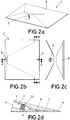
Figure 2a-2d show different views of a prism according to an embodiment of the invention, drawing (A) shows a schematic perspective view, drawing (B) a top view, drawing (C) a cross-sectional view along the B-B axis depicted in drawing (B), and drawing (D) a cross-sectional view along the A-A axis depicted in drawing (B). -
Figure 3a-3c show different views of a first connection element according to an embodiment of the invention, drawing (A) shows a schematic perspective view, drawing (B) a longitudinal sectional view, and drawing (C) a cross-sectional view. -
Figure 4a-4c show different views of a second connection element according to an embodiment of the invention, drawing (A) shows a schematic perspective view, drawing (B) a longitudinal sectional view, and drawing (C) a cross-sectional view. -
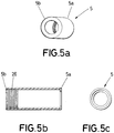
Figure 5a-5c show different views of an optical fibre connection device according to an embodiment of the present invention, drawing (A) shows a schematic perspective view, drawing (B) a longitudinal sectional view, and drawing (C) a cross-sectional view. -
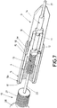
Figures 6-8 show different views of the pieces forming the optical fibre connection device, according to an embodiment of the invention. -
Figure 1 shows an optical fibre connection device 1 for acomposite structure 20 according to a preferred embodiment. -
Figure 1c shows acomposite structure 20 comprising an optical fibre connection device 1. The optical fibre connection device 1 can be placed at any location of the composite surface, no longer needed, as conventionally, to be placed at one edge of the structure. Thus, the invention is compatible with trimming process of composite structures. - According to the invention, the device 1 at least comprises a
metallic prism 2, first andsecond connection elements closure 5, inner andouter ferrules 11, 12 (figures 6-8 ), and an elastic element 13 (figures 6-8 ). - As shown in
Figure 1 , theprism 2 has aplanar base 6 for laying on acomposite structure 20 in which the inputoptical fiber 21 is embedded. To allow the connection of the inputoptical fiber 21 with an outeroptical fibre 22, theprism 2 is further provided with aninner conduit 7. Theconduit 7 ends in first andsecond bores - As
Figure 2a shows, first andsecond bores prism 2. Thefirst bore 8 is configured to receive the inputoptical fiber 21 embedded in thecomposite structure 20, while thesecond bore 9 is configured to receive thefirst connection element 3. - As shown in
Figure 2d , theinner conduit 7 of theprism 2 comprises twosections 7', 7" following different orientations, such as a ramp with anobtuse angle 10 is formed inside the prism. The ramp leads the inputoptical fiber 21 towards the input and outputoptical fibers - As shown in
Figure 2d , and according to a preferred embodiment, a part of theinner conduit 7 of theprism 2 has a funnel shaped configuration. Further, according to another preferred embodiment, theinner conduit 7 of theprism 2 has a threadedinner surface 23. -
Figure 3 shows afirst connection element 3 according to a preferred embodiment. Thefirst connection element 3 has a tubular shaped configuration with inner andouter ends inner end 3a is configured to be inserted into thesecond bore 9 of theprism 2 to receive the inputoptical fiber 21. Theouter end 3b is inwardly configured to receive theinner end 4a of thesecond connection element 4, and outwardly configured to receive theclosure 5. To receive thesecond connection element 4, theouter end 3b offirst connection element 3 has aninner box 30, and to receive theclosure 5, theouter end 3b offirst connection element 3 has a threadedouter surface 25. - The connection between the first 3 and
second connection element 4 admit an unique position, the right one according to the polish angle in the ferrules, as consequence of the keyway and key machined in both respectively first and second connection elements. - Preferably, as shown in
Figures 3a-3b , theinner end 3a of thefirst connection element 3 has a nozzle-shaped configuration that mates with a funnel shaped configuration provided at theinner conduit 7 of the prism 2 (Figure 2d ) to ease the connection between them. - Likewise, as preferably shown in
Figures 3a-3b , theinner end 3a of thefirst connection element 3 has a threadedouter surface 24 threaded with a threadedinner surface 23 provided at theinner conduit 7 of theprism 2. This way, the device 1 provides a resistant connection between theprism 2 and thefirst connection element 3. -
Figure 4 shows asecond connection element 4 according to a preferred embodiment. Thesecond connection element 4 has a tubular shaped configuration with inner andouter ends inner end 4a is configured to be inserted into thefirst connection element 3, and theouter end 4b is configured to receive an outputoptical fiber 22. To receive thefirst connection element 3, theinner end 4a of thesecond connection element 4 has an outer protruding 31 configured to be received by theinner box 30 of theouter end 3b offirst connection element 3. The device 1 thus provides a unique position for the connection, which allows providing an optimal optic alignment with minimum optical insertion losses. - Preferably, as shown in
Figures 4a-4b , theinner end 3a of thefirst connection element 3 has a nozzle-shaped configuration that mates with a funnel shaped configuration provided at theinner conduit 7 of the prism 2 (Figure 2d ) to ease the connection between them. - As shown in
Figures 4a-4b , and according to a preferred embodiment, theouter end 4b of thesecond connection element 4 has a threadedinner surface 29 to receive and retain a piece (e.g. a stopper 19) adapted to maintain theelastic element 13 pressing the inner andouter ferrules fibres -
Figure 5 shows aclosure 5 according to a preferred embodiment. Theclosure 5 has a tubular shaped configuration with inner andouter ends closure 5 is configured to be disposed around the outer ends 4b, 3b of the second andfirst connection elements second connection elements - Preferably, as shown in
Figures 5a-5b , theinner end 5a of theclosure 5 has a threadedinner surface 26 threaded with a threadedouter surface 25 provided at theouter end 3b of thefirst connection element 3. This way, the device 1 provides a resistant connection between the first andsecond connection elements - Further to the
prism 2, the first andsecond connection elements closure 5, the optical fibre connection device 1 also comprises inner andouter ferrules elastic element 13.Figures 6 to 8 show longitudinal sectional views of the optical fibre connection device 1 in which theferrules elastic element 13 can be appreciated. - As shown in
Figure 6 , the inputoptical fiber 21 end is received by theinner ferrule 11, and the outputoptical fiber 22 end is received by theouter ferrule 12. - Preferably, the inner and the
outer ferrules - As shown in
Figures 7-8 , the bothferrules inner end 4a of thesecond connection element 4, providing this way a tight connection between the input and outputoptical fibers - As also shown in
Figures 7-8 , theelastic element 13 retained into theouter end 4b of thesecond connection element 4 presses the inner andouter ferrules optical fibers - According to a preferred embodiment, the optical fibre connection device 1 further comprises an
inner connector 14 having a tubular shaped configuration allocated into theinner end 3a of thefirst connection element 3 to provide a tight connection between the inputoptical fiber 21 end and theinner ferrule 11, and anouter connector 15 having a tubular shaped configuration allocated into theouter end 4b of thesecond connection element 4 to provide a tight connection between the outputoptical fiber end 22 and theouter ferrule 12. - According to another preferred embodiment, a
tubular sheath 16 can be coaxially disposed around the inner 11 and theouter ferrule 12 to further protect the input and outputoptical fibers - In addition, the optical fibre connection device 1 can be configured to ensure that the fibers connection occurs at a desired position. According to this, the
second connection element 4 may have ashoulder 18 between the inner and theouter end outer end 3b of thefirst connection element 3. - Likewise, according to another preferred embodiment, the
closure 5 has anouter end 5b with anoutward projection 17 that mates with theouter end 4b of thesecond connection element 4, to thus close the first andsecond connection element - As shown in
Figures 7-8 , and according to another preferred embodiment, the optical fibre connection device 1 further comprises astopper 19 configured to be inserted into theouter end 4b of thesecond connection element 4 to maintain theelastic element 13 pressing the inner andouter ferrules - Preferably, the
stopper 19 has a threadedouter surface 27 and an outward flaredsurface 28, the threadedouter surface 27 threaded with a threadedinner surface 29 provided at theouter end 4b of thesecond connection element 4, and the outward flaredsurface 28 configured to retain the first andsecond connection element - Preferably, the outward flared
surface 28 of thestopper 19 contacts theoutward projection 17 of theclosure 5 to retain the first andsecond connection element
Claims (14)
- An optical fibre connection device (1) comprising,- a metallic prism (2) having a planar base (6) to lay on a composite structure (20), the prism (2) having an inner conduit (7) connecting opposing lateral surfaces of the prism (2), the conduit (7) ending in a first and second bores (8, 9), the first bore (8) being configured to receive an input optical fiber (21) embedded in the composite structure (20),- a first connection element (3) having a tubular shaped configuration with inner and outer ends (3a, 3b), the inner end (3a) configured to be inserted into the second bore (9) of the prism (2) to receive the input optical fiber (21), and- a second connection element (4) having a tubular shaped configuration with inner and outer ends (4a, 4b), the inner end (4a) configured to be inserted into the first connection element (3), and the outer end (4b) configured to receive an output optical fiber (22),characterized in that- the outer end (3b) of first connection element (3) has an inner box (30) configured to receive an outer protruding (31) provided at the inner end (4a) of the second connection element (4) to provide a unique position for the connection of the input and output optical fibers (21, 22),in that- the inner conduit (7) of the prism (2) comprises two sections (7', 7") following different orientations, said orientations forming a ramp to lead the input optical fiber (21) towards the input and output optical fibers (21, 22) connection,and in that the optical fibre connection device (1) further comprises:- an inner and outer ferrules (11, 12) to respectively receive the input and output optical fiber (21, 22) ends,- the inner and outer ferrules (11, 12) consecutively disposed along the inner end (4a) of the second connection element (4) to provide tight connection between the input and output optical fibers (21, 22), and- an elastic element (13) retained into the outer end (4b) of the second connection element (4) pressing the inner and outer ferrules (11, 12) together, to thus connect the input and output optical fibers (21, 22).
- An optical fibre connection device (1) according to claim 1 further comprising:- an inner connector (14) having a tubular shaped configuration allocated into the inner end (3a) of the first connection element (3) to provide a tight connection between the input optical fiber (21) end and the inner ferrule (11), and- an outer connector (15) having a tubular shaped configuration allocated into the outer end (4b) of the second connection element (4) to provide a tight connection between the output optical fiber end (22) and the outer ferrule (12).
- An optical fibre connection device (1) according to any of the preceding claims further comprising a tubular sheath (16) coaxially disposed around the inner (11) and the outer ferrule (12).
- An optical fibre connection device (1) according to any of the preceding claims, further comprising a closure (5) coaxially disposed around the outer end (4b, 3b) of the second and first connection element (4, 3) to close the first and second connection element (3, 4) together.
- An optical fibre connection device (1) according to claim 4 wherein the closure (5) has an outer end (5b) with an outward projection (17) that mates with the outer end (4b) of the second connection element (4) to close the first and second connection element (3, 4) at a desired position.
- An optical fibre connection device (1) according to any of claims 4-5, wherein the closure (5) has a threaded inner surface (26) threaded with a threaded outer surface (25) provided at the outer end (3b) of the first connection element (3).
- An optical fibre connection device (1) according to any of the preceding claims, wherein the second connection element (4) has a shoulder (18) between the inner and the outer end (4a, 4b), the shoulder (18) contacting the outer end (3b) of the first connection element (3) to retain the first and second connection element (3, 4) at a desired position.
- An optical fibre connection device (1) according to any of the preceding claims, further comprising a stopper (19) configured to be inserted into the outer end (4b) of the second connection element (4) to maintain the elastic element (13) pressing the inner and outer ferrules (11, 12) together.
- An optical fibre connection device (1) according to claim 8, wherein the stopper (19) has a threaded outer surface (27) and an outward flared surface (28), the threaded outer surface (27) threaded with a threaded inner surface (29) provided at the outer end (4b) of the second connection element (4), and the outward flared surface (28) configured to retain the first and second connection element (3, 4) at a desired position.
- An optical fibre connection device (1) according to claims 5 and 9, wherein the outward flared surface (28) of the stopper (19) contacts the outward projection (17) of the closure (5) to retain the first and second connection element (3, 4) at a desired position.
- An optical fibre connection device (1) according to any of the preceding claims, wherein the inner conduit (7) of the prism (2) has a threaded inner surface (23) threaded with a threaded outer surface (24) provided at the inner end (3a) of the first connection element (3).
- An optical fibre connection device (1) according to any of the preceding claims, wherein the first connection element (3) has an inner end (3a) with a nozzle-shaped configuration that mates with a funnel shaped configuration provided at the inner conduit (7) of the prism (2) to ease the connection between them.
- A composite structure (20) for an aircraft, comprising an optical fibre connection device (1) according to any of claims 1-12, and an outer composite layer, wherein the outer composite layer is disposed on the optical fibre connection device (1).
- Method for manufacturing a composite structure (20) for an aircraft, comprising the steps of:- providing at least one layer of composite material,- providing an input optical fiber (21),- providing at least one layer of composite material on the input optical fiber (21) to provide a composite structure (20) having an embedded input optical fiber (21),- providing an optical fibre connection device (1) comprising:- a metallic prism (2) having a planar base (6) to lay on the composite structure (20), the prism (2) having an inner conduit (7) connecting opposing lateral surfaces of the prism (2), the conduit (7) ending in a first and second bores (8, 9), the first bore (8) being configured to receive an input optical fiber (21) embedded in the composite structure (20),- a first connection element (3) having a tubular shaped configuration with inner and outer ends (3a, 3b), the inner end (3a) configured to be inserted into the second bore (9) of the prism (2) to receive the input optical fiber (21), and- a second connection element (4) having a tubular shaped configuration with inner and outer ends (4a, 4b), the inner end (4a) configured to be inserted into the first connection element (3), and the outer end (4b) configured to receive an output optical fiber (22),- an inner and outer ferrules (11, 12) to respectively receive the input and output optical fiber (21, 22) ends, and- an elastic element (13) retained into the outer end (4b) of the second connection element (4) pressing the inner and outer ferrules (11, 12) together,- wherein, the outer end (3b) of first connection element (3) has an inner box (30) configured to receive an outer protruding (31) provided at the inner end (4a) of the second connection element (4) to provide a unique position for the connection of the input and output optical fibers (21, 22),- wherein, the inner conduit (7) of the prism (2) comprises two sections (7', 7") following different orientations, said orientations forming a ramp to lead the input optical fiber (21) towards the input and output optical fibers (21, 22) connection, and- wherein, the inner and outer ferrules (11, 12) consecutively disposed along the inner end (4a) of the second connection element (4) to provide tight connection between the input and output optical fibers (21, 22),- providing at least one layer of composite material on the optical fibre connection device (1).
Priority Applications (4)
| Application Number | Priority Date | Filing Date | Title |
|---|---|---|---|
| ES16382635T ES2810854T3 (en) | 2016-12-21 | 2016-12-21 | Fiber optic connection device for a composite structure, composite structure for an aircraft and manufacturing process of the same |
| EP16382635.7A EP3339925B1 (en) | 2016-12-21 | 2016-12-21 | Optical fibre connection device for a composite structure, composite structure for an aircraft, and manufacturing method thereof |
| US15/845,350 US10197744B2 (en) | 2016-12-21 | 2017-12-18 | Optical fiber connector device for a composite structure, composite structure for an aircraft, and manufacturing method thereof |
| CN201711395316.5A CN108227081B (en) | 2016-12-21 | 2017-12-21 | Optical fiber connection device, composite structure of aircraft and manufacturing method thereof |
Applications Claiming Priority (1)
| Application Number | Priority Date | Filing Date | Title |
|---|---|---|---|
| EP16382635.7A EP3339925B1 (en) | 2016-12-21 | 2016-12-21 | Optical fibre connection device for a composite structure, composite structure for an aircraft, and manufacturing method thereof |
Publications (2)
| Publication Number | Publication Date |
|---|---|
| EP3339925A1 true EP3339925A1 (en) | 2018-06-27 |
| EP3339925B1 EP3339925B1 (en) | 2020-05-06 |
Family
ID=57681513
Family Applications (1)
| Application Number | Title | Priority Date | Filing Date |
|---|---|---|---|
| EP16382635.7A Active EP3339925B1 (en) | 2016-12-21 | 2016-12-21 | Optical fibre connection device for a composite structure, composite structure for an aircraft, and manufacturing method thereof |
Country Status (4)
| Country | Link |
|---|---|
| US (1) | US10197744B2 (en) |
| EP (1) | EP3339925B1 (en) |
| CN (1) | CN108227081B (en) |
| ES (1) | ES2810854T3 (en) |
Citations (3)
| Publication number | Priority date | Publication date | Assignee | Title |
|---|---|---|---|---|
| US20040017981A1 (en) * | 1997-09-11 | 2004-01-29 | Jovanovich Stevan Bogdan | Capillary valve, connector, and router |
| WO2005103786A1 (en) * | 2004-04-20 | 2005-11-03 | Deutsch Uk | Waveguide assembly and connector |
| US20100166371A1 (en) * | 2008-12-30 | 2010-07-01 | Airbus Espana S.L. | Fiber optic connection device for composite structures |
Family Cites Families (4)
| Publication number | Priority date | Publication date | Assignee | Title |
|---|---|---|---|---|
| CN201413419Y (en) * | 2009-03-24 | 2010-02-24 | 中航光电科技股份有限公司 | A kind of optical cable connector |
| US8290332B2 (en) * | 2009-08-13 | 2012-10-16 | Commscope, Inc. Of North Carolina | Optical fiber adapter |
| US20140099061A1 (en) * | 2012-10-05 | 2014-04-10 | Corning Cable Systems Llc | Reconfigurable fiber optic cable assemblies and optical connectors |
| CN105044853B (en) * | 2015-06-28 | 2017-08-04 | 中航光电科技股份有限公司 | An optical fiber contact component |
-
2016
- 2016-12-21 EP EP16382635.7A patent/EP3339925B1/en active Active
- 2016-12-21 ES ES16382635T patent/ES2810854T3/en active Active
-
2017
- 2017-12-18 US US15/845,350 patent/US10197744B2/en active Active
- 2017-12-21 CN CN201711395316.5A patent/CN108227081B/en active Active
Patent Citations (3)
| Publication number | Priority date | Publication date | Assignee | Title |
|---|---|---|---|---|
| US20040017981A1 (en) * | 1997-09-11 | 2004-01-29 | Jovanovich Stevan Bogdan | Capillary valve, connector, and router |
| WO2005103786A1 (en) * | 2004-04-20 | 2005-11-03 | Deutsch Uk | Waveguide assembly and connector |
| US20100166371A1 (en) * | 2008-12-30 | 2010-07-01 | Airbus Espana S.L. | Fiber optic connection device for composite structures |
Also Published As
| Publication number | Publication date |
|---|---|
| US20180172921A1 (en) | 2018-06-21 |
| EP3339925B1 (en) | 2020-05-06 |
| US10197744B2 (en) | 2019-02-05 |
| CN108227081B (en) | 2021-03-02 |
| ES2810854T3 (en) | 2021-03-09 |
| CN108227081A (en) | 2018-06-29 |
Similar Documents
| Publication | Publication Date | Title |
|---|---|---|
| EP2241912B1 (en) | Embeddable fiber optic connector and associated method | |
| US9612407B2 (en) | Optical coupler for multicore fiber | |
| US8068714B2 (en) | Optical waveguide feedthrough assembly | |
| US7556437B2 (en) | Fiber optic connector with protective cap | |
| US5355429A (en) | Optical fiber strain relief apparatus | |
| US20080156971A1 (en) | Modular sensor for damage detection, manufacturing method, and structural composite material | |
| JPS5817928B2 (en) | Kodensoubuzaino Setsuzokusouchi | |
| JP4626535B2 (en) | Tape optical fiber cable | |
| US9235009B2 (en) | Optical connector and method of preventing protection tube from coming off from optical connector | |
| US11550103B2 (en) | Optical connection component | |
| US12013579B1 (en) | Optical interconnect devices | |
| US20090034916A1 (en) | Fiber optic cable with in-line fiber optic splice | |
| CN107702659A (en) | The distributed temperature strain transducer and preparation method of carbon fiber prepreg encapsulation | |
| EP3339925A1 (en) | Optical fibre connection device for a composite structure, composite structure for an aircraft, and manufacturing method thereof | |
| CN111811685A (en) | A kind of fiber grating temperature sensor, assembly and manufacturing method | |
| EP2914994B1 (en) | Terminus assembly for terminating an optical cable | |
| US9964711B1 (en) | Optical cable for avionics applications, method of manufacture thereof and articles comprising the same | |
| CN213122391U (en) | Optical fiber coding optical fiber sheath structure and loose-sleeve tail fiber | |
| JP2024106759A (en) | Optical fiber bundle, optical connection structure, and method for manufacturing optical fiber bundle | |
| JP2013213934A (en) | Optical connection member and manufacturing method for the same | |
| JP2007127878A (en) | Optical waveguide connection structure | |
| EP0890856A1 (en) | Optical coupler | |
| JP4946338B2 (en) | Tape-like optical fiber for laying structures and manufacturing method thereof | |
| US8781280B2 (en) | Cable expansion joint | |
| CN202421545U (en) | Field optical fiber rapid connection component |
Legal Events
| Date | Code | Title | Description |
|---|---|---|---|
| PUAI | Public reference made under article 153(3) epc to a published international application that has entered the european phase |
Free format text: ORIGINAL CODE: 0009012 |
|
| STAA | Information on the status of an ep patent application or granted ep patent |
Free format text: STATUS: THE APPLICATION HAS BEEN PUBLISHED |
|
| AK | Designated contracting states |
Kind code of ref document: A1 Designated state(s): AL AT BE BG CH CY CZ DE DK EE ES FI FR GB GR HR HU IE IS IT LI LT LU LV MC MK MT NL NO PL PT RO RS SE SI SK SM TR |
|
| AX | Request for extension of the european patent |
Extension state: BA ME |
|
| STAA | Information on the status of an ep patent application or granted ep patent |
Free format text: STATUS: REQUEST FOR EXAMINATION WAS MADE |
|
| 17P | Request for examination filed |
Effective date: 20181213 |
|
| RBV | Designated contracting states (corrected) |
Designated state(s): AL AT BE BG CH CY CZ DE DK EE ES FI FR GB GR HR HU IE IS IT LI LT LU LV MC MK MT NL NO PL PT RO RS SE SI SK SM TR |
|
| GRAP | Despatch of communication of intention to grant a patent |
Free format text: ORIGINAL CODE: EPIDOSNIGR1 |
|
| STAA | Information on the status of an ep patent application or granted ep patent |
Free format text: STATUS: GRANT OF PATENT IS INTENDED |
|
| GRAS | Grant fee paid |
Free format text: ORIGINAL CODE: EPIDOSNIGR3 |
|
| GRAA | (expected) grant |
Free format text: ORIGINAL CODE: 0009210 |
|
| STAA | Information on the status of an ep patent application or granted ep patent |
Free format text: STATUS: THE PATENT HAS BEEN GRANTED |
|
| INTG | Intention to grant announced |
Effective date: 20200316 |
|
| AK | Designated contracting states |
Kind code of ref document: B1 Designated state(s): AL AT BE BG CH CY CZ DE DK EE ES FI FR GB GR HR HU IE IS IT LI LT LU LV MC MK MT NL NO PL PT RO RS SE SI SK SM TR |
|
| REG | Reference to a national code |
Ref country code: GB Ref legal event code: FG4D |
|
| REG | Reference to a national code |
Ref country code: AT Ref legal event code: REF Ref document number: 1267692 Country of ref document: AT Kind code of ref document: T Effective date: 20200515 Ref country code: CH Ref legal event code: EP |
|
| REG | Reference to a national code |
Ref country code: IE Ref legal event code: FG4D |
|
| REG | Reference to a national code |
Ref country code: DE Ref legal event code: R096 Ref document number: 602016035654 Country of ref document: DE |
|
| REG | Reference to a national code |
Ref country code: LT Ref legal event code: MG4D |
|
| REG | Reference to a national code |
Ref country code: NL Ref legal event code: MP Effective date: 20200506 |
|
| PG25 | Lapsed in a contracting state [announced via postgrant information from national office to epo] |
Ref country code: PT Free format text: LAPSE BECAUSE OF FAILURE TO SUBMIT A TRANSLATION OF THE DESCRIPTION OR TO PAY THE FEE WITHIN THE PRESCRIBED TIME-LIMIT Effective date: 20200907 Ref country code: SE Free format text: LAPSE BECAUSE OF FAILURE TO SUBMIT A TRANSLATION OF THE DESCRIPTION OR TO PAY THE FEE WITHIN THE PRESCRIBED TIME-LIMIT Effective date: 20200506 Ref country code: LT Free format text: LAPSE BECAUSE OF FAILURE TO SUBMIT A TRANSLATION OF THE DESCRIPTION OR TO PAY THE FEE WITHIN THE PRESCRIBED TIME-LIMIT Effective date: 20200506 Ref country code: IS Free format text: LAPSE BECAUSE OF FAILURE TO SUBMIT A TRANSLATION OF THE DESCRIPTION OR TO PAY THE FEE WITHIN THE PRESCRIBED TIME-LIMIT Effective date: 20200906 Ref country code: GR Free format text: LAPSE BECAUSE OF FAILURE TO SUBMIT A TRANSLATION OF THE DESCRIPTION OR TO PAY THE FEE WITHIN THE PRESCRIBED TIME-LIMIT Effective date: 20200807 Ref country code: NO Free format text: LAPSE BECAUSE OF FAILURE TO SUBMIT A TRANSLATION OF THE DESCRIPTION OR TO PAY THE FEE WITHIN THE PRESCRIBED TIME-LIMIT Effective date: 20200806 Ref country code: FI Free format text: LAPSE BECAUSE OF FAILURE TO SUBMIT A TRANSLATION OF THE DESCRIPTION OR TO PAY THE FEE WITHIN THE PRESCRIBED TIME-LIMIT Effective date: 20200506 |
|
| PG25 | Lapsed in a contracting state [announced via postgrant information from national office to epo] |
Ref country code: BG Free format text: LAPSE BECAUSE OF FAILURE TO SUBMIT A TRANSLATION OF THE DESCRIPTION OR TO PAY THE FEE WITHIN THE PRESCRIBED TIME-LIMIT Effective date: 20200806 Ref country code: RS Free format text: LAPSE BECAUSE OF FAILURE TO SUBMIT A TRANSLATION OF THE DESCRIPTION OR TO PAY THE FEE WITHIN THE PRESCRIBED TIME-LIMIT Effective date: 20200506 Ref country code: HR Free format text: LAPSE BECAUSE OF FAILURE TO SUBMIT A TRANSLATION OF THE DESCRIPTION OR TO PAY THE FEE WITHIN THE PRESCRIBED TIME-LIMIT Effective date: 20200506 Ref country code: LV Free format text: LAPSE BECAUSE OF FAILURE TO SUBMIT A TRANSLATION OF THE DESCRIPTION OR TO PAY THE FEE WITHIN THE PRESCRIBED TIME-LIMIT Effective date: 20200506 |
|
| REG | Reference to a national code |
Ref country code: AT Ref legal event code: MK05 Ref document number: 1267692 Country of ref document: AT Kind code of ref document: T Effective date: 20200506 |
|
| PG25 | Lapsed in a contracting state [announced via postgrant information from national office to epo] |
Ref country code: AL Free format text: LAPSE BECAUSE OF FAILURE TO SUBMIT A TRANSLATION OF THE DESCRIPTION OR TO PAY THE FEE WITHIN THE PRESCRIBED TIME-LIMIT Effective date: 20200506 Ref country code: NL Free format text: LAPSE BECAUSE OF FAILURE TO SUBMIT A TRANSLATION OF THE DESCRIPTION OR TO PAY THE FEE WITHIN THE PRESCRIBED TIME-LIMIT Effective date: 20200506 |
|
| PG25 | Lapsed in a contracting state [announced via postgrant information from national office to epo] |
Ref country code: AT Free format text: LAPSE BECAUSE OF FAILURE TO SUBMIT A TRANSLATION OF THE DESCRIPTION OR TO PAY THE FEE WITHIN THE PRESCRIBED TIME-LIMIT Effective date: 20200506 Ref country code: EE Free format text: LAPSE BECAUSE OF FAILURE TO SUBMIT A TRANSLATION OF THE DESCRIPTION OR TO PAY THE FEE WITHIN THE PRESCRIBED TIME-LIMIT Effective date: 20200506 Ref country code: IT Free format text: LAPSE BECAUSE OF FAILURE TO SUBMIT A TRANSLATION OF THE DESCRIPTION OR TO PAY THE FEE WITHIN THE PRESCRIBED TIME-LIMIT Effective date: 20200506 Ref country code: SM Free format text: LAPSE BECAUSE OF FAILURE TO SUBMIT A TRANSLATION OF THE DESCRIPTION OR TO PAY THE FEE WITHIN THE PRESCRIBED TIME-LIMIT Effective date: 20200506 Ref country code: DK Free format text: LAPSE BECAUSE OF FAILURE TO SUBMIT A TRANSLATION OF THE DESCRIPTION OR TO PAY THE FEE WITHIN THE PRESCRIBED TIME-LIMIT Effective date: 20200506 Ref country code: CZ Free format text: LAPSE BECAUSE OF FAILURE TO SUBMIT A TRANSLATION OF THE DESCRIPTION OR TO PAY THE FEE WITHIN THE PRESCRIBED TIME-LIMIT Effective date: 20200506 Ref country code: RO Free format text: LAPSE BECAUSE OF FAILURE TO SUBMIT A TRANSLATION OF THE DESCRIPTION OR TO PAY THE FEE WITHIN THE PRESCRIBED TIME-LIMIT Effective date: 20200506 |
|
| REG | Reference to a national code |
Ref country code: DE Ref legal event code: R097 Ref document number: 602016035654 Country of ref document: DE |
|
| PG25 | Lapsed in a contracting state [announced via postgrant information from national office to epo] |
Ref country code: SK Free format text: LAPSE BECAUSE OF FAILURE TO SUBMIT A TRANSLATION OF THE DESCRIPTION OR TO PAY THE FEE WITHIN THE PRESCRIBED TIME-LIMIT Effective date: 20200506 Ref country code: PL Free format text: LAPSE BECAUSE OF FAILURE TO SUBMIT A TRANSLATION OF THE DESCRIPTION OR TO PAY THE FEE WITHIN THE PRESCRIBED TIME-LIMIT Effective date: 20200506 |
|
| REG | Reference to a national code |
Ref country code: ES Ref legal event code: FG2A Ref document number: 2810854 Country of ref document: ES Kind code of ref document: T3 Effective date: 20210309 |
|
| PLBE | No opposition filed within time limit |
Free format text: ORIGINAL CODE: 0009261 |
|
| STAA | Information on the status of an ep patent application or granted ep patent |
Free format text: STATUS: NO OPPOSITION FILED WITHIN TIME LIMIT |
|
| 26N | No opposition filed |
Effective date: 20210209 |
|
| PG25 | Lapsed in a contracting state [announced via postgrant information from national office to epo] |
Ref country code: SI Free format text: LAPSE BECAUSE OF FAILURE TO SUBMIT A TRANSLATION OF THE DESCRIPTION OR TO PAY THE FEE WITHIN THE PRESCRIBED TIME-LIMIT Effective date: 20200506 |
|
| REG | Reference to a national code |
Ref country code: CH Ref legal event code: PL |
|
| PG25 | Lapsed in a contracting state [announced via postgrant information from national office to epo] |
Ref country code: MC Free format text: LAPSE BECAUSE OF FAILURE TO SUBMIT A TRANSLATION OF THE DESCRIPTION OR TO PAY THE FEE WITHIN THE PRESCRIBED TIME-LIMIT Effective date: 20200506 |
|
| REG | Reference to a national code |
Ref country code: BE Ref legal event code: MM Effective date: 20201231 |
|
| PG25 | Lapsed in a contracting state [announced via postgrant information from national office to epo] |
Ref country code: IE Free format text: LAPSE BECAUSE OF NON-PAYMENT OF DUE FEES Effective date: 20201221 Ref country code: LU Free format text: LAPSE BECAUSE OF NON-PAYMENT OF DUE FEES Effective date: 20201221 |
|
| PG25 | Lapsed in a contracting state [announced via postgrant information from national office to epo] |
Ref country code: CH Free format text: LAPSE BECAUSE OF NON-PAYMENT OF DUE FEES Effective date: 20201231 Ref country code: LI Free format text: LAPSE BECAUSE OF NON-PAYMENT OF DUE FEES Effective date: 20201231 |
|
| PG25 | Lapsed in a contracting state [announced via postgrant information from national office to epo] |
Ref country code: TR Free format text: LAPSE BECAUSE OF FAILURE TO SUBMIT A TRANSLATION OF THE DESCRIPTION OR TO PAY THE FEE WITHIN THE PRESCRIBED TIME-LIMIT Effective date: 20200506 Ref country code: MT Free format text: LAPSE BECAUSE OF FAILURE TO SUBMIT A TRANSLATION OF THE DESCRIPTION OR TO PAY THE FEE WITHIN THE PRESCRIBED TIME-LIMIT Effective date: 20200506 Ref country code: CY Free format text: LAPSE BECAUSE OF FAILURE TO SUBMIT A TRANSLATION OF THE DESCRIPTION OR TO PAY THE FEE WITHIN THE PRESCRIBED TIME-LIMIT Effective date: 20200506 |
|
| PG25 | Lapsed in a contracting state [announced via postgrant information from national office to epo] |
Ref country code: MK Free format text: LAPSE BECAUSE OF FAILURE TO SUBMIT A TRANSLATION OF THE DESCRIPTION OR TO PAY THE FEE WITHIN THE PRESCRIBED TIME-LIMIT Effective date: 20200506 |
|
| PG25 | Lapsed in a contracting state [announced via postgrant information from national office to epo] |
Ref country code: BE Free format text: LAPSE BECAUSE OF NON-PAYMENT OF DUE FEES Effective date: 20201231 |
|
| PGFP | Annual fee paid to national office [announced via postgrant information from national office to epo] |
Ref country code: DE Payment date: 20251211 Year of fee payment: 10 |
|
| PGFP | Annual fee paid to national office [announced via postgrant information from national office to epo] |
Ref country code: GB Payment date: 20251219 Year of fee payment: 10 |
|
| PGFP | Annual fee paid to national office [announced via postgrant information from national office to epo] |
Ref country code: FR Payment date: 20251229 Year of fee payment: 10 |
|
| PGFP | Annual fee paid to national office [announced via postgrant information from national office to epo] |
Ref country code: ES Payment date: 20260130 Year of fee payment: 10 |