EP3339919A1 - Vehicle lighting apparatus - Google Patents
Vehicle lighting apparatus Download PDFInfo
- Publication number
- EP3339919A1 EP3339919A1 EP17205347.2A EP17205347A EP3339919A1 EP 3339919 A1 EP3339919 A1 EP 3339919A1 EP 17205347 A EP17205347 A EP 17205347A EP 3339919 A1 EP3339919 A1 EP 3339919A1
- Authority
- EP
- European Patent Office
- Prior art keywords
- light
- reflection
- image
- lighting apparatus
- vehicle
- Prior art date
- Legal status (The legal status is an assumption and is not a legal conclusion. Google has not performed a legal analysis and makes no representation as to the accuracy of the status listed.)
- Granted
Links
Images



Classifications
-
- G—PHYSICS
- G03—PHOTOGRAPHY; CINEMATOGRAPHY; ANALOGOUS TECHNIQUES USING WAVES OTHER THAN OPTICAL WAVES; ELECTROGRAPHY; HOLOGRAPHY
- G03B—APPARATUS OR ARRANGEMENTS FOR TAKING PHOTOGRAPHS OR FOR PROJECTING OR VIEWING THEM; APPARATUS OR ARRANGEMENTS EMPLOYING ANALOGOUS TECHNIQUES USING WAVES OTHER THAN OPTICAL WAVES; ACCESSORIES THEREFOR
- G03B21/00—Projectors or projection-type viewers; Accessories therefor
- G03B21/14—Details
- G03B21/147—Optical correction of image distortions, e.g. keystone
-
- B—PERFORMING OPERATIONS; TRANSPORTING
- B60—VEHICLES IN GENERAL
- B60Q—ARRANGEMENT OF SIGNALLING OR LIGHTING DEVICES, THE MOUNTING OR SUPPORTING THEREOF OR CIRCUITS THEREFOR, FOR VEHICLES IN GENERAL
- B60Q1/00—Arrangement of optical signalling or lighting devices, the mounting or supporting thereof or circuits therefor
- B60Q1/02—Arrangement of optical signalling or lighting devices, the mounting or supporting thereof or circuits therefor the devices being primarily intended to illuminate the way ahead or to illuminate other areas of way or environments
- B60Q1/04—Arrangement of optical signalling or lighting devices, the mounting or supporting thereof or circuits therefor the devices being primarily intended to illuminate the way ahead or to illuminate other areas of way or environments the devices being headlights
-
- B—PERFORMING OPERATIONS; TRANSPORTING
- B60—VEHICLES IN GENERAL
- B60Q—ARRANGEMENT OF SIGNALLING OR LIGHTING DEVICES, THE MOUNTING OR SUPPORTING THEREOF OR CIRCUITS THEREFOR, FOR VEHICLES IN GENERAL
- B60Q1/00—Arrangement of optical signalling or lighting devices, the mounting or supporting thereof or circuits therefor
- B60Q1/02—Arrangement of optical signalling or lighting devices, the mounting or supporting thereof or circuits therefor the devices being primarily intended to illuminate the way ahead or to illuminate other areas of way or environments
- B60Q1/04—Arrangement of optical signalling or lighting devices, the mounting or supporting thereof or circuits therefor the devices being primarily intended to illuminate the way ahead or to illuminate other areas of way or environments the devices being headlights
- B60Q1/06—Arrangement of optical signalling or lighting devices, the mounting or supporting thereof or circuits therefor the devices being primarily intended to illuminate the way ahead or to illuminate other areas of way or environments the devices being headlights adjustable, e.g. remotely-controlled from inside vehicle
- B60Q1/08—Arrangement of optical signalling or lighting devices, the mounting or supporting thereof or circuits therefor the devices being primarily intended to illuminate the way ahead or to illuminate other areas of way or environments the devices being headlights adjustable, e.g. remotely-controlled from inside vehicle automatically
- B60Q1/085—Arrangement of optical signalling or lighting devices, the mounting or supporting thereof or circuits therefor the devices being primarily intended to illuminate the way ahead or to illuminate other areas of way or environments the devices being headlights adjustable, e.g. remotely-controlled from inside vehicle automatically due to special conditions, e.g. adverse weather, type of road, badly illuminated road signs or potential dangers
-
- B—PERFORMING OPERATIONS; TRANSPORTING
- B60—VEHICLES IN GENERAL
- B60Q—ARRANGEMENT OF SIGNALLING OR LIGHTING DEVICES, THE MOUNTING OR SUPPORTING THEREOF OR CIRCUITS THEREFOR, FOR VEHICLES IN GENERAL
- B60Q1/00—Arrangement of optical signalling or lighting devices, the mounting or supporting thereof or circuits therefor
- B60Q1/26—Arrangement of optical signalling or lighting devices, the mounting or supporting thereof or circuits therefor the devices being primarily intended to indicate the vehicle, or parts thereof, or to give signals, to other traffic
- B60Q1/50—Arrangement of optical signalling or lighting devices, the mounting or supporting thereof or circuits therefor the devices being primarily intended to indicate the vehicle, or parts thereof, or to give signals, to other traffic for indicating other intentions or conditions, e.g. request for waiting or overtaking
-
- F—MECHANICAL ENGINEERING; LIGHTING; HEATING; WEAPONS; BLASTING
- F21—LIGHTING
- F21S—NON-PORTABLE LIGHTING DEVICES; SYSTEMS THEREOF; VEHICLE LIGHTING DEVICES SPECIALLY ADAPTED FOR VEHICLE EXTERIORS
- F21S41/00—Illuminating devices specially adapted for vehicle exteriors, e.g. headlamps
- F21S41/10—Illuminating devices specially adapted for vehicle exteriors, e.g. headlamps characterised by the light source
- F21S41/14—Illuminating devices specially adapted for vehicle exteriors, e.g. headlamps characterised by the light source characterised by the type of light source
- F21S41/141—Light emitting diodes [LED]
- F21S41/147—Light emitting diodes [LED] the main emission direction of the LED being angled to the optical axis of the illuminating device
-
- F—MECHANICAL ENGINEERING; LIGHTING; HEATING; WEAPONS; BLASTING
- F21—LIGHTING
- F21S—NON-PORTABLE LIGHTING DEVICES; SYSTEMS THEREOF; VEHICLE LIGHTING DEVICES SPECIALLY ADAPTED FOR VEHICLE EXTERIORS
- F21S41/00—Illuminating devices specially adapted for vehicle exteriors, e.g. headlamps
- F21S41/10—Illuminating devices specially adapted for vehicle exteriors, e.g. headlamps characterised by the light source
- F21S41/14—Illuminating devices specially adapted for vehicle exteriors, e.g. headlamps characterised by the light source characterised by the type of light source
- F21S41/16—Laser light sources
-
- F—MECHANICAL ENGINEERING; LIGHTING; HEATING; WEAPONS; BLASTING
- F21—LIGHTING
- F21S—NON-PORTABLE LIGHTING DEVICES; SYSTEMS THEREOF; VEHICLE LIGHTING DEVICES SPECIALLY ADAPTED FOR VEHICLE EXTERIORS
- F21S41/00—Illuminating devices specially adapted for vehicle exteriors, e.g. headlamps
- F21S41/20—Illuminating devices specially adapted for vehicle exteriors, e.g. headlamps characterised by refractors, transparent cover plates, light guides or filters
- F21S41/25—Projection lenses
-
- F—MECHANICAL ENGINEERING; LIGHTING; HEATING; WEAPONS; BLASTING
- F21—LIGHTING
- F21S—NON-PORTABLE LIGHTING DEVICES; SYSTEMS THEREOF; VEHICLE LIGHTING DEVICES SPECIALLY ADAPTED FOR VEHICLE EXTERIORS
- F21S41/00—Illuminating devices specially adapted for vehicle exteriors, e.g. headlamps
- F21S41/20—Illuminating devices specially adapted for vehicle exteriors, e.g. headlamps characterised by refractors, transparent cover plates, light guides or filters
- F21S41/25—Projection lenses
- F21S41/255—Lenses with a front view of circular or truncated circular outline
-
- F—MECHANICAL ENGINEERING; LIGHTING; HEATING; WEAPONS; BLASTING
- F21—LIGHTING
- F21S—NON-PORTABLE LIGHTING DEVICES; SYSTEMS THEREOF; VEHICLE LIGHTING DEVICES SPECIALLY ADAPTED FOR VEHICLE EXTERIORS
- F21S41/00—Illuminating devices specially adapted for vehicle exteriors, e.g. headlamps
- F21S41/20—Illuminating devices specially adapted for vehicle exteriors, e.g. headlamps characterised by refractors, transparent cover plates, light guides or filters
- F21S41/25—Projection lenses
- F21S41/265—Composite lenses; Lenses with a patch-like shape
-
- F—MECHANICAL ENGINEERING; LIGHTING; HEATING; WEAPONS; BLASTING
- F21—LIGHTING
- F21S—NON-PORTABLE LIGHTING DEVICES; SYSTEMS THEREOF; VEHICLE LIGHTING DEVICES SPECIALLY ADAPTED FOR VEHICLE EXTERIORS
- F21S41/00—Illuminating devices specially adapted for vehicle exteriors, e.g. headlamps
- F21S41/30—Illuminating devices specially adapted for vehicle exteriors, e.g. headlamps characterised by reflectors
- F21S41/32—Optical layout thereof
- F21S41/33—Multi-surface reflectors, e.g. reflectors with facets or reflectors with portions of different curvature
- F21S41/334—Multi-surface reflectors, e.g. reflectors with facets or reflectors with portions of different curvature the reflector consisting of patch like sectors
- F21S41/336—Multi-surface reflectors, e.g. reflectors with facets or reflectors with portions of different curvature the reflector consisting of patch like sectors with discontinuity at the junction between adjacent areas
-
- F—MECHANICAL ENGINEERING; LIGHTING; HEATING; WEAPONS; BLASTING
- F21—LIGHTING
- F21S—NON-PORTABLE LIGHTING DEVICES; SYSTEMS THEREOF; VEHICLE LIGHTING DEVICES SPECIALLY ADAPTED FOR VEHICLE EXTERIORS
- F21S41/00—Illuminating devices specially adapted for vehicle exteriors, e.g. headlamps
- F21S41/30—Illuminating devices specially adapted for vehicle exteriors, e.g. headlamps characterised by reflectors
- F21S41/32—Optical layout thereof
- F21S41/36—Combinations of two or more separate reflectors
-
- F—MECHANICAL ENGINEERING; LIGHTING; HEATING; WEAPONS; BLASTING
- F21—LIGHTING
- F21S—NON-PORTABLE LIGHTING DEVICES; SYSTEMS THEREOF; VEHICLE LIGHTING DEVICES SPECIALLY ADAPTED FOR VEHICLE EXTERIORS
- F21S41/00—Illuminating devices specially adapted for vehicle exteriors, e.g. headlamps
- F21S41/30—Illuminating devices specially adapted for vehicle exteriors, e.g. headlamps characterised by reflectors
- F21S41/32—Optical layout thereof
- F21S41/36—Combinations of two or more separate reflectors
- F21S41/365—Combinations of two or more separate reflectors successively reflecting the light
-
- F—MECHANICAL ENGINEERING; LIGHTING; HEATING; WEAPONS; BLASTING
- F21—LIGHTING
- F21S—NON-PORTABLE LIGHTING DEVICES; SYSTEMS THEREOF; VEHICLE LIGHTING DEVICES SPECIALLY ADAPTED FOR VEHICLE EXTERIORS
- F21S41/00—Illuminating devices specially adapted for vehicle exteriors, e.g. headlamps
- F21S41/60—Illuminating devices specially adapted for vehicle exteriors, e.g. headlamps characterised by a variable light distribution
- F21S41/67—Illuminating devices specially adapted for vehicle exteriors, e.g. headlamps characterised by a variable light distribution by acting on reflectors
- F21S41/675—Illuminating devices specially adapted for vehicle exteriors, e.g. headlamps characterised by a variable light distribution by acting on reflectors by moving reflectors
-
- G—PHYSICS
- G02—OPTICS
- G02B—OPTICAL ELEMENTS, SYSTEMS OR APPARATUS
- G02B13/00—Optical objectives specially designed for the purposes specified below
- G02B13/16—Optical objectives specially designed for the purposes specified below for use in conjunction with image converters or intensifiers, or for use with projectors, e.g. objectives for projection TV
-
- G—PHYSICS
- G02—OPTICS
- G02B—OPTICAL ELEMENTS, SYSTEMS OR APPARATUS
- G02B5/00—Optical elements other than lenses
- G02B5/08—Mirrors
- G02B5/10—Mirrors with curved faces
-
- G—PHYSICS
- G03—PHOTOGRAPHY; CINEMATOGRAPHY; ANALOGOUS TECHNIQUES USING WAVES OTHER THAN OPTICAL WAVES; ELECTROGRAPHY; HOLOGRAPHY
- G03B—APPARATUS OR ARRANGEMENTS FOR TAKING PHOTOGRAPHS OR FOR PROJECTING OR VIEWING THEM; APPARATUS OR ARRANGEMENTS EMPLOYING ANALOGOUS TECHNIQUES USING WAVES OTHER THAN OPTICAL WAVES; ACCESSORIES THEREFOR
- G03B21/00—Projectors or projection-type viewers; Accessories therefor
- G03B21/14—Details
- G03B21/28—Reflectors in projection beam
-
- G—PHYSICS
- G03—PHOTOGRAPHY; CINEMATOGRAPHY; ANALOGOUS TECHNIQUES USING WAVES OTHER THAN OPTICAL WAVES; ELECTROGRAPHY; HOLOGRAPHY
- G03B—APPARATUS OR ARRANGEMENTS FOR TAKING PHOTOGRAPHS OR FOR PROJECTING OR VIEWING THEM; APPARATUS OR ARRANGEMENTS EMPLOYING ANALOGOUS TECHNIQUES USING WAVES OTHER THAN OPTICAL WAVES; ACCESSORIES THEREFOR
- G03B29/00—Combinations of cameras, projectors or photographic printing apparatus with non-photographic non-optical apparatus, e.g. clocks or weapons; Cameras having the shape of other objects
-
- B—PERFORMING OPERATIONS; TRANSPORTING
- B60—VEHICLES IN GENERAL
- B60Q—ARRANGEMENT OF SIGNALLING OR LIGHTING DEVICES, THE MOUNTING OR SUPPORTING THEREOF OR CIRCUITS THEREFOR, FOR VEHICLES IN GENERAL
- B60Q2300/00—Indexing codes for automatically adjustable headlamps or automatically dimmable headlamps
- B60Q2300/40—Indexing codes relating to other road users or special conditions
- B60Q2300/42—Indexing codes relating to other road users or special conditions oncoming vehicle
-
- B—PERFORMING OPERATIONS; TRANSPORTING
- B60—VEHICLES IN GENERAL
- B60Q—ARRANGEMENT OF SIGNALLING OR LIGHTING DEVICES, THE MOUNTING OR SUPPORTING THEREOF OR CIRCUITS THEREFOR, FOR VEHICLES IN GENERAL
- B60Q2300/00—Indexing codes for automatically adjustable headlamps or automatically dimmable headlamps
- B60Q2300/40—Indexing codes relating to other road users or special conditions
- B60Q2300/45—Special conditions, e.g. pedestrians, road signs or potential dangers
-
- B—PERFORMING OPERATIONS; TRANSPORTING
- B60—VEHICLES IN GENERAL
- B60Q—ARRANGEMENT OF SIGNALLING OR LIGHTING DEVICES, THE MOUNTING OR SUPPORTING THEREOF OR CIRCUITS THEREFOR, FOR VEHICLES IN GENERAL
- B60Q2400/00—Special features or arrangements of exterior signal lamps for vehicles
- B60Q2400/50—Projected symbol or information, e.g. onto the road or car body
-
- F—MECHANICAL ENGINEERING; LIGHTING; HEATING; WEAPONS; BLASTING
- F21—LIGHTING
- F21W—INDEXING SCHEME ASSOCIATED WITH SUBCLASSES F21K, F21L, F21S and F21V, RELATING TO USES OR APPLICATIONS OF LIGHTING DEVICES OR SYSTEMS
- F21W2103/00—Exterior vehicle lighting devices for signalling purposes
- F21W2103/60—Projection of signs from lighting devices, e.g. symbols or information being projected onto the road
Definitions
- the present invention relates to a vehicle lighting apparatus.
- An object of an aspect of the present invention is to provide a vehicle lighting apparatus that is capable of clearly displaying an image on a road surface.
- An aspect of the present invention is a vehicle lighting apparatus that emits light diagonally toward a road surface from a vehicle, the apparatus including: a light source; an image generation part that modulates light emitted from the light source and that generates an image; a light-focusing optical system that focuses light having the image generated by the image generation part; and a reflection part that reflects light focused by the light-focusing optical system and that projects reflected light on a road surface, wherein the reflection part has a reflection surface having a curvature that is gradually increased from a projection direction rearward side toward a projection direction frontward side.
- the reflection surface is a convex curved surface or is a concave curved surface, compared to a case in which light is reflected at a region that reflects light toward a far position from the vehicle, light is reflected at a region that reflects light toward a near position from the vehicle, the distance between a region where light is reflected on the reflection surface and a region where an image is formed on the road surface, which is an imaging surface, is shortened, and it is possible to prevent a defocus of the imaged light distribution pattern. Accordingly, it is possible to provide a vehicle lighting apparatus that is capable of clearly displaying an image on a road surface.
- the vehicle lighting apparatus described above may include: a plurality of the reflection parts, each of which reflects light toward each of regions on the road surface having a different distance from each other; and a switch part that switches and arranges one of the plurality of the reflection parts to a light-receiving position of light emitted from the light-focusing optical system.
- the plurality of the reflection parts each of which reflects light toward each of regions having a different distance from each other, are switched by the switch part and are arranged at the light-receiving position, and therefore, it is possible to clearly display an image at a position having a different distance on the road surface by each reflection part. Therefore, by switching the reflection part in accordance with an application, it is possible to clearly display an image at a position suitable for each application.
- the vehicle lighting apparatus described above may include a return mirror that reflects light emitted from the light-focusing optical system toward the reflection part.
- the configuration since the light from the light-focusing optical system is reflected toward the reflection part by the return mirror, it is not necessary to arrange the light-focusing optical system in a direction that faces the reflection part, and it is possible to decrease the thickness in the vertical direction of the light-focusing optical system and decrease the size in the vertical direction of the vehicle lighting apparatus.
- the reflection surface may have a concave shape and may be arranged at a latter part of an intermediate image formed by the light-focusing optical system.
- a reflection surface having a concave shape is employed, and it is possible to display a clear image on the road surface.
- the reflection surface may have a convex shape and may be arranged at a former part of an intermediate image formed by the light-focusing optical system.
- a reflection surface having a convex shape is employed, and it is possible to display a clear image on the road surface.
- the vehicle lighting apparatus described above may include: an object detection part that detects an object which is present at a frontward position of the vehicle; and a control part that controls the image of the image generation part and a switch mode of the reflection part in the switch part based on a detection condition of the object detection part.
- the configuration it is possible to change the direction and position of the display in accordance with frontward circumstances of the vehicle, and therefore, the information of the image displayed on the road surface can be easily understood by a person in the vicinity of the vehicle.
- the vehicle lighting apparatus described above may employ a configuration in which the control part changes any one of or both of a direction of the image and a projection position of the image in accordance with frontward circumstances of the vehicle.
- the vehicle lighting apparatus of the aspect of the present invention it is possible to provide a vehicle lighting apparatus that is capable of clearly displaying an image on a road surface.
- FIG. 1 is a schematic view of a vehicle lighting apparatus 10 according to a first embodiment.
- the vehicle lighting apparatus 10 of the present embodiment is an apparatus that emits light, which has an image, diagonally toward a road surface from a vehicle.
- the vehicle lighting apparatus 10 includes a projection module 11 that illuminates a frontward direction of a vehicle, a control device 13 that controls the projection module 11, and an imaging device 15 that detects frontward circumstances and that transmits the frontward circumstances to the control device 13.
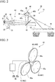
- FIG. 2 is a schematic view showing the projection module 11 of the present embodiment.
- the projection module 11 of the present embodiment includes a light source 21, an incident optical system 25, an image generation part 31, and a projection optical system 41.
- the light source 21 emits visible light.
- a light-emitting diode (LED) light source or a laser light source can be employed as the light source 21.
- the incident optical system 25 is formed of one or more lenses and the like that focus light from the light source 21 and irradiate a reflection control surface of the image generation part 31.
- the image generation part 31 modulates light emitted from the light source 21 and generates an image.
- the image generation part 31 is formed of a reflection-type digital light deflection device (DMD, Digital Mirror Device).
- the image generation part 31 formed of the reflection-type digital light deflection device has the reflection control surface configured by arranging a plurality of mirror elements capable of being slanted.
- a slant angle of each of the plurality of mirror elements of the image generation part 31 is controlled to a reflection side or a light shield side by a signal from the control device 13.
- the image generation part 31 generates a reflection pattern (image) 39 having an arbitrary shape by reflection light of the plurality of mirror elements slanted to the reflection side.
- the image generation part 31 generates a reflection pattern 39 having an arrow shape.
- a light shield member 32 that blocks light from each mirror element slanted to the light shield side is provided on the vehicle lighting apparatus 10.
- the projection optical system 41 illuminates a frontward direction of the vehicle with the reflection pattern 39 generated by the image generation part 31 as a light distribution pattern 49.
- the projection optical system 41 includes a light-focusing optical system 42, a return mirror 43, and a reflection device 44.
- the light-focusing optical system 42 is formed of one or more lenses and the like.
- the light-focusing optical system 42 illuminates a reflection part 45 of the reflection device 44 with the reflection pattern 39 generated by the image generation part 31 via the return mirror 43.
- the light-focusing optical system 42 focuses the reflection pattern 39 emitted from the image generation part 31 and forms an intermediate image 59.
- the return mirror 43 is a mirror that reflects light from the light-focusing optical system 42 toward the reflection part 45.
- FIG. 3 is a perspective view of the reflection device 44.
- the reflection device 44 has a plurality of (three in the present embodiment) reflection parts 45 and a switch part 46.
- the reflection part 45 reflects light focused by the light-focusing optical system 42 toward a road surface 57.
- the switch part 46 has a shaft part 46a and a drive part 46b that drives the shaft part 46a to be rotated around the shaft.
- a plurality of reflection parts 45 are fixed to the shaft part 46a at even intervals along a circumferential direction with respect to the shaft center of the shaft part 46a.
- the switch part 46 switches and arranges one of the plurality of the reflection parts 45 to a light-receiving position at which light emitted from the light-focusing optical system 42 is received in accordance with the rotation of the shaft part 46a by the drive part 46b.
- FIG. 1 and FIG. 2 only one reflection part 45 of the plurality of reflection parts 45 that is arranged at the light-receiving position is shown.
- the reflection part 45 is a concave reflector used for an expansion projection.
- the reflection part 45 has a reflection surface 45a.
- the reflection part 45 reflects light focused by the light-focusing optical system 42 at the reflection surface 45a and projects reflected light onto a predetermined region of the road surface 57.
- the reflection surface 45a has a concave shape formed of an aspherical free-form surface.
- the reflection surface 45a is arranged at a latter part of the intermediate image 59 formed by the light-focusing optical system 42. Accordingly, light forms an image at a former part side of the reflection surface 45a, is incident on the reflection surface 45a having a concave shape while extending in a diffusion direction, and is reflected by the reflection surface 45a to thereby be focused again.
- the "former part” and the “latter part” mean a sequence relationship (that is, an upstream side and a downstream side in an optical path) along a transmission path of light and do not mean the arrangement of each part in the vehicle lighting apparatus 10.
- a projection direction frontward region 45b of the reflection surface 45a reflects light toward the road surface 57 on a vehicle near side.
- a projection direction rearward region 45c of the reflection surface 45a reflects light toward the road surface 57 on a vehicle far side.
- the reflection surface 45a is formed to have a curvature that is continuously changed from the projection direction rearward region 45c toward the projection direction frontward region 45b in accordance with the distance to a projection target (a near position from the vehicle to a far position from the vehicle of the road surface 57). That is, the reflection surface 45a has a curvature that is gradually increased from a projection direction rearward side toward a projection direction frontward side.
- the distance between a region where light is reflected on the reflection surface 45a and a region where an image is formed on the road surface 57, which is an imaging surface, is shortened, and it is possible to prevent a defocus of the imaged light distribution pattern 49.
- the reflection device 44 of the present embodiment has a short-distance reflection part 45X, a middle-distance reflection part 45Y, and a long-distance reflection part 45Z.
- the reflection surface 45a of each of the reflection parts 45X, 45Y, and 45Z is set so as to reflect light toward each of regions on the road surface 57 having a different distance from one another.
- Each reflection surface 45a of the short-distance reflection part 45X, the middle-distance reflection part 45Y, and the long-distance reflection part 45Z is formed such that as the reflection surface 45a has a shorter distance to the position which is irradiated with reflection light, the reflection surface 45a has a curved surface having a larger average curvature.
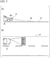
- Part (a) and part (b) of FIG. 4 show a state in which the road surface 57 is irradiated with the light distribution pattern 49 using the short-distance reflection part 45X.
- Part (a) and part (b) of FIG. 5 show a state in which the road surface 57 is irradiated with the light distribution pattern 49 using the middle-distance reflection part 45Y.
- Part (a) and part (b) of FIG. 6 show a state in which the road surface 57 is irradiated with the light distribution pattern 49 using the long-distance reflection part 45Z.
- the imaging device 15 that controls the projection module 11 has an object detection part 52 that detects, by capturing an image of a frontward direction of a vehicle and processing the image, an object that is present in the frontward direction of the vehicle and transmits a detection signal to a control part 51.
- control device 13 has a configuration that is capable of performing a process of controlling a slant mode of the mirror element of the image generation part 31 to thereby form an image and, at the same time, arranging a reflection part 45 selected from a plurality of reflection parts 45 by the switch part 46 to a light-receiving position from the light-focusing optical system 42.
- the control device 13 has a memory 53 in which control information of a variety of images and the like are set in advance, the control part 51 that generates a control signal based on information from the memory 53 and a signal from the imaging device 15, and a drive part 54 that drives part of or all of the light source 21, the image generation part 31, and the reflection device 44 based on the control signal.
- the control part 51 controls the image by the slant mode of each mirror element of the image generation part 31 via the drive part 54 and controls a switch mode in which any of the reflection parts 45 of the reflection device 44 is arranged at the light-receiving position based on a detection condition of the object detection part 52 or an input operation of a driver and the like.
- the middle-distance reflection part 45Y is switched to and arranged at the light-receiving position in the reflection device 44.
- the image generation part 31 an image that is directed in the near side and that is adapted for the driver and the like with respect to information requested by the driver and the like is generated, and light from the light source 21 is emitted from the light-focusing optical system 42. Thereby, it is possible to display an image having an appropriate direction when seen from the driver, on the road surface 57.
- information such as a legal speed, route guidance, and warning of a frontward obstacle in an appropriate direction when seen from the driver can be displayed on the road surface 57 for the driver at a middle-distance position of the road surface 57.
- the long-distance reflection part 45Z is switched to and arranged at the light-receiving position in the reflection device 44.
- the image generation part 31 an inversely directed image that is adapted for the driver of the oncoming vehicle 58 is generated, and light from the light source 21 is emitted from the light-focusing optical system 42. Thereby, it is possible to display an image having an appropriate direction when seen from the driver of the oncoming vehicle 58, on the road surface 57.
- the reflection part 45 that reflects light having an image as the reflection pattern 39 toward the road surface 57 is formed to have a curvature that is continuously changed in accordance with the distance to a projection target (a near position from the vehicle to a far position from the vehicle of the road surface). Thereby, it is possible to clearly display an image on the road surface 57, and it is possible to draw a high-quality image without a defocus.
- the plurality of the reflection parts 45 each of which reflects light toward each of regions having a different distance from each other, can be switched by the switch part 46 and can be arranged at the light-receiving position.
- the switch part 46 By switching the reflection part 45 in accordance with an application, it is possible to provide a vehicle lighting apparatus 10 that clearly displays an image at a position suitable for each application. Further, when emitting reflection light to a long distance, it is possible to prevent the light from diffusing and to prevent the illumination intensity from being decreased.
- the vehicle lighting apparatus 10 of the present embodiment includes the object detection part 52 and the control part 51 that controls the image of the image generation part 31 and a switch mode of the reflection part 45 based on a detection condition of the object detection part 52. Therefore, it is possible to change the direction and position of the display in accordance with frontward circumstances of the vehicle, and the information of the image displayed on the road surface can be easily understood by a person in the vicinity of the vehicle.
- the control part 51 changes the image generated on the image generation part 31 and changes the direction of the image in accordance with frontward circumstances of the vehicle. Further, in the vehicle lighting apparatus 10 of the present embodiment, the control part 51 selects any of the short-distance reflection part 45X, the middle-distance reflection part 45Y, and the long-distance reflection part 45Z and thereby changes the projection position of the image in accordance with frontward circumstances of the vehicle. Thereby, it is possible to project necessary information on the road surface such that the information is easily seen in accordance with frontward circumstances of the vehicle.
- the first embodiment described above can be arbitrarily changed without departing from the scope of the invention.
- the combination of the selection from the short-distance reflection part 45X, the middle-distance reflection part 45Y, and the long-distance reflection part 45Z and the direction of the image is not limited.
- the vehicle lighting apparatus 10 of the present embodiment since the light from the light-focusing optical system 42 is reflected toward the reflection part 45 by the return mirror 43, it is not necessary to arrange the light-focusing optical system 42 in a direction that faces the reflection part 45. Thereby, it is possible to decrease the thickness in the vertical direction of the light-focusing optical system 42 and decrease the size in the vertical direction of the vehicle lighting apparatus 10. Thereby, it is possible to easily downsize a housing of the vehicle lighting apparatus 10.
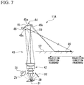
- FIG. 7 shows a projection module 11A of a modified example that is adoptable in the present embodiment.
- the projection module 11A is different in that the projection module 11A does not include the return mirror 43 compared to the embodiment described above. According to the present modified example, it is possible to reduce the number of components and to provide a low-cost vehicle lighting apparatus 10.
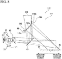
- FIG. 8 is a schematic view showing a projection module 111 of a vehicle lighting apparatus 110 of a second embodiment.
- the vehicle lighting apparatus 110 of the present embodiment includes a reflection device 144 having a reflection part 145.
- the reflection part 145 has a reflection surface 145a having a convex shape.
- the reflection surface 145a is arranged at a former part of an intermediate image 159 formed by the light-focusing optical system 42. Accordingly, light is incident on the reflection surface 145a having a convex shape while being focused, the distance between the reflection surface and the imaging surface is adjusted by the reflection surface 145a, and the light is reflected in the frontward direction.
- the reflection surface 145a having a convex shape has a curvature that is gradually increased from a projection direction rearward side toward a projection direction frontward side.
- a projection direction frontward region 145b of the reflection surface 145a reflects light toward the road surface 57 on a vehicle far side.
- a projection direction rearward region 145c of the reflection surface 145a reflects light toward the road surface 57 on a vehicle near side.
- the reflection surface 145a is formed to have a curvature that is continuously changed from the projection direction rearward region 145c toward the projection direction frontward region 145b in accordance with the distance to a projection target (a near position from the vehicle to a far position from the vehicle of the road surface 57). That is, the reflection surface 145a has a curvature that is gradually increased from a projection direction rearward side toward a projection direction frontward side.
- the distance between a region where light is reflected on the reflection surface 145a and a region where an image is formed on the road surface 57, which is an imaging surface, is shortened, and it is possible to prevent a defocus of the imaged light distribution pattern 49.
- the vehicle lighting apparatus 10 as described above may be provided separately from a headlight or may be incorporated in a headlight.
- a reflection-type digital light deflection device is used as the image generation part 31; however, a transmission-type spatial modulator such as liquid crystal, a drawing apparatus that combines a scanning mirror and phosphor, and the like may be used.
Landscapes
- Engineering & Computer Science (AREA)
- Physics & Mathematics (AREA)
- General Engineering & Computer Science (AREA)
- General Physics & Mathematics (AREA)
- Optics & Photonics (AREA)
- Mechanical Engineering (AREA)
- Microelectronics & Electronic Packaging (AREA)
- Lighting Device Outwards From Vehicle And Optical Signal (AREA)
- Non-Portable Lighting Devices Or Systems Thereof (AREA)
Abstract
Description
- The present invention relates to a vehicle lighting apparatus.
- In the related art, as a vehicle lighting apparatus, vehicle lighting apparatuses that use the contrast of light and display an image indicating information on a road surface have been proposed. In Japanese Patent No.
4059079 - However, in the vehicle lighting apparatus of the related art, when a variety of images are displayed on a road surface, since an imaging surface is not matched with the road surface, the distance between the image on the road surface and a lens at a near side of the image is greatly different from the distance between the image on the road surface and the lens at a far side of the image. Therefore, there is a problem in that a defocus occurs in which an image is formed at some position, but an image is not formed at frontward and rearward positions of the some position.
- An object of an aspect of the present invention is to provide a vehicle lighting apparatus that is capable of clearly displaying an image on a road surface.
- An aspect of the present invention is a vehicle lighting apparatus that emits light diagonally toward a road surface from a vehicle, the apparatus including: a light source; an image generation part that modulates light emitted from the light source and that generates an image; a light-focusing optical system that focuses light having the image generated by the image generation part; and a reflection part that reflects light focused by the light-focusing optical system and that projects reflected light on a road surface, wherein the reflection part has a reflection surface having a curvature that is gradually increased from a projection direction rearward side toward a projection direction frontward side.
- According to the configuration, even when the reflection surface is a convex curved surface or is a concave curved surface, compared to a case in which light is reflected at a region that reflects light toward a far position from the vehicle, light is reflected at a region that reflects light toward a near position from the vehicle, the distance between a region where light is reflected on the reflection surface and a region where an image is formed on the road surface, which is an imaging surface, is shortened, and it is possible to prevent a defocus of the imaged light distribution pattern. Accordingly, it is possible to provide a vehicle lighting apparatus that is capable of clearly displaying an image on a road surface.
- The vehicle lighting apparatus described above may include: a plurality of the reflection parts, each of which reflects light toward each of regions on the road surface having a different distance from each other; and a switch part that switches and arranges one of the plurality of the reflection parts to a light-receiving position of light emitted from the light-focusing optical system.
- According to the configuration, the plurality of the reflection parts, each of which reflects light toward each of regions having a different distance from each other, are switched by the switch part and are arranged at the light-receiving position, and therefore, it is possible to clearly display an image at a position having a different distance on the road surface by each reflection part. Therefore, by switching the reflection part in accordance with an application, it is possible to clearly display an image at a position suitable for each application.
- The vehicle lighting apparatus described above may include a return mirror that reflects light emitted from the light-focusing optical system toward the reflection part.
- According to the configuration, since the light from the light-focusing optical system is reflected toward the reflection part by the return mirror, it is not necessary to arrange the light-focusing optical system in a direction that faces the reflection part, and it is possible to decrease the thickness in the vertical direction of the light-focusing optical system and decrease the size in the vertical direction of the vehicle lighting apparatus.
- In the vehicle lighting apparatus described above, the reflection surface may have a concave shape and may be arranged at a latter part of an intermediate image formed by the light-focusing optical system.
- According to the configuration, a reflection surface having a concave shape is employed, and it is possible to display a clear image on the road surface.
- In the vehicle lighting apparatus described above, the reflection surface may have a convex shape and may be arranged at a former part of an intermediate image formed by the light-focusing optical system.
- According to the configuration, a reflection surface having a convex shape is employed, and it is possible to display a clear image on the road surface.
- The vehicle lighting apparatus described above may include: an object detection part that detects an object which is present at a frontward position of the vehicle; and a control part that controls the image of the image generation part and a switch mode of the reflection part in the switch part based on a detection condition of the object detection part.
- According to the configuration, it is possible to change the direction and position of the display in accordance with frontward circumstances of the vehicle, and therefore, the information of the image displayed on the road surface can be easily understood by a person in the vicinity of the vehicle.
- The vehicle lighting apparatus described above may employ a configuration in which the control part changes any one of or both of a direction of the image and a projection position of the image in accordance with frontward circumstances of the vehicle.
- According to the configuration, it is possible to project necessary information on the road surface such that the information is easily seen in accordance with frontward circumstances of the vehicle.
- According to the vehicle lighting apparatus of the aspect of the present invention, it is possible to provide a vehicle lighting apparatus that is capable of clearly displaying an image on a road surface.
-
-
FIG. 1 is a schematic view of a vehicle lighting apparatus according to a first embodiment. -
FIG. 2 is a schematic view of a projection module of the vehicle lighting apparatus according to the first embodiment. -
FIG. 3 is a perspective view showing a switch part of the vehicle lighting apparatus according to the first embodiment. - Part (a) of
FIG. 4 is a perspective view showing a state in which a road surface is irradiated using a short-distance reflection part in the vehicle lighting apparatus according to the first embodiment. Part (b) ofFIG. 4 is a plan view showing the state in which the road surface is irradiated using the short-distance reflection part in the vehicle lighting apparatus according to the first embodiment. - Part (a) of
FIG. 5 is a perspective view showing a state in which a road surface is irradiated using a middle-distance reflection part in the vehicle lighting apparatus according to the first embodiment. Part (b) ofFIG. 5 is a plan view showing the state in which the road surface is irradiated using the middle-distance reflection part in the vehicle lighting apparatus according to the first embodiment. - Part (a) of
FIG. 6 is a perspective view showing a state in which a road surface is irradiated using a long-distance reflection part in the vehicle lighting apparatus according to the first embodiment. Part (b) ofFIG. 6 is a plan view showing the state in which the road surface is irradiated using the long-distance reflection part in the vehicle lighting apparatus according to the first embodiment. -
FIG. 7 is a schematic view of a projection module of a vehicle lighting apparatus according to a modified example of the first embodiment. -
FIG. 8 is a schematic view of a projection module of a vehicle lighting apparatus according to a second embodiment. -
- 10, 110 ··· VEHICLE LIGHTING APPARATUS
- 21 ··· LIGHT SOURCE
- 31 ··· IMAGE GENERATION PART
- 39 ··· REFLECTION PATTERN (IMAGE)
- 42 ··· LIGHT-FOCUSING OPTICAL SYSTEM
- 43 ··· RETURN MIRROR
- 45, 45X, 45Y, 45Z, 145 ··· REFLECTION PART
- 45a, 145a ··· REFLECTION SURFACE
- 46 ··· SWITCH PART
- 51 ··· CONTROL PART
- 52 ··· OBJECT DETECTION PART
- 55 ··· VEHICLE
- 57 ··· ROAD SURFACE
- 59, 159 ··· INTERMEDIATE IMAGE
- Hereinafter, a vehicle lighting apparatus according to an embodiment is described with reference to the drawings.
- In the drawings used in the following description, there may be a case in which, for ease of understanding the features, the featured part is shown to be enlarged, and the dimension ratio of each component or the like is not always the same as an actual one.
-
FIG. 1 is a schematic view of avehicle lighting apparatus 10 according to a first embodiment. - The
vehicle lighting apparatus 10 of the present embodiment is an apparatus that emits light, which has an image, diagonally toward a road surface from a vehicle. - As shown in
FIG. 1 , thevehicle lighting apparatus 10 includes aprojection module 11 that illuminates a frontward direction of a vehicle, acontrol device 13 that controls theprojection module 11, and animaging device 15 that detects frontward circumstances and that transmits the frontward circumstances to thecontrol device 13. -
FIG. 2 is a schematic view showing theprojection module 11 of the present embodiment. - The
projection module 11 of the present embodiment includes alight source 21, an incidentoptical system 25, animage generation part 31, and a projectionoptical system 41. - The
light source 21 emits visible light. A light-emitting diode (LED) light source or a laser light source can be employed as thelight source 21. - The incident
optical system 25 is formed of one or more lenses and the like that focus light from thelight source 21 and irradiate a reflection control surface of theimage generation part 31. - The
image generation part 31 modulates light emitted from thelight source 21 and generates an image. In the present embodiment, theimage generation part 31 is formed of a reflection-type digital light deflection device (DMD, Digital Mirror Device). Theimage generation part 31 formed of the reflection-type digital light deflection device has the reflection control surface configured by arranging a plurality of mirror elements capable of being slanted. - A slant angle of each of the plurality of mirror elements of the
image generation part 31 is controlled to a reflection side or a light shield side by a signal from thecontrol device 13. Theimage generation part 31 generates a reflection pattern (image) 39 having an arbitrary shape by reflection light of the plurality of mirror elements slanted to the reflection side. In the example shown inFIG. 2 , theimage generation part 31 generates areflection pattern 39 having an arrow shape. - A
light shield member 32 that blocks light from each mirror element slanted to the light shield side is provided on thevehicle lighting apparatus 10. - The projection
optical system 41 illuminates a frontward direction of the vehicle with thereflection pattern 39 generated by theimage generation part 31 as alight distribution pattern 49. The projectionoptical system 41 includes a light-focusingoptical system 42, areturn mirror 43, and areflection device 44. - The light-focusing
optical system 42 is formed of one or more lenses and the like. The light-focusingoptical system 42 illuminates areflection part 45 of thereflection device 44 with thereflection pattern 39 generated by theimage generation part 31 via thereturn mirror 43. The light-focusingoptical system 42 focuses thereflection pattern 39 emitted from theimage generation part 31 and forms anintermediate image 59. - The
return mirror 43 is a mirror that reflects light from the light-focusingoptical system 42 toward thereflection part 45. -
FIG. 3 is a perspective view of thereflection device 44. - The
reflection device 44 has a plurality of (three in the present embodiment)reflection parts 45 and aswitch part 46. Thereflection part 45 reflects light focused by the light-focusingoptical system 42 toward aroad surface 57. Theswitch part 46 has ashaft part 46a and adrive part 46b that drives theshaft part 46a to be rotated around the shaft. - A plurality of
reflection parts 45 are fixed to theshaft part 46a at even intervals along a circumferential direction with respect to the shaft center of theshaft part 46a. Theswitch part 46 switches and arranges one of the plurality of thereflection parts 45 to a light-receiving position at which light emitted from the light-focusingoptical system 42 is received in accordance with the rotation of theshaft part 46a by thedrive part 46b. - In
FIG. 1 andFIG. 2 , only onereflection part 45 of the plurality ofreflection parts 45 that is arranged at the light-receiving position is shown. - The
reflection part 45 is a concave reflector used for an expansion projection. Thereflection part 45 has areflection surface 45a. Thereflection part 45 reflects light focused by the light-focusingoptical system 42 at thereflection surface 45a and projects reflected light onto a predetermined region of theroad surface 57. Thereflection surface 45a has a concave shape formed of an aspherical free-form surface. - The
reflection surface 45a is arranged at a latter part of theintermediate image 59 formed by the light-focusingoptical system 42. Accordingly, light forms an image at a former part side of thereflection surface 45a, is incident on thereflection surface 45a having a concave shape while extending in a diffusion direction, and is reflected by thereflection surface 45a to thereby be focused again. - The "former part" and the "latter part" mean a sequence relationship (that is, an upstream side and a downstream side in an optical path) along a transmission path of light and do not mean the arrangement of each part in the
vehicle lighting apparatus 10. - A projection direction frontward
region 45b of thereflection surface 45a reflects light toward theroad surface 57 on a vehicle near side. A projection direction rearwardregion 45c of thereflection surface 45a reflects light toward theroad surface 57 on a vehicle far side. Thereflection surface 45a is formed to have a curvature that is continuously changed from the projection direction rearwardregion 45c toward the projection direction frontwardregion 45b in accordance with the distance to a projection target (a near position from the vehicle to a far position from the vehicle of the road surface 57). That is, thereflection surface 45a has a curvature that is gradually increased from a projection direction rearward side toward a projection direction frontward side. Thereby, compared to a case in which light is reflected at the projection direction rearwardregion 45c that reflects light toward a far position from the vehicle, light is reflected at the projection direction frontwardregion 45b that reflects light toward a near position from the vehicle, the distance between a region where light is reflected on thereflection surface 45a and a region where an image is formed on theroad surface 57, which is an imaging surface, is shortened, and it is possible to prevent a defocus of the imagedlight distribution pattern 49. - As shown in
FIG. 3 , thereflection device 44 of the present embodiment has a short-distance reflection part 45X, a middle-distance reflection part 45Y, and a long-distance reflection part 45Z. Thereflection surface 45a of each of thereflection parts road surface 57 having a different distance from one another. Eachreflection surface 45a of the short-distance reflection part 45X, the middle-distance reflection part 45Y, and the long-distance reflection part 45Z is formed such that as thereflection surface 45a has a shorter distance to the position which is irradiated with reflection light, thereflection surface 45a has a curved surface having a larger average curvature. Part (a) and part (b) ofFIG. 4 show a state in which theroad surface 57 is irradiated with thelight distribution pattern 49 using the short-distance reflection part 45X. Part (a) and part (b) ofFIG. 5 show a state in which theroad surface 57 is irradiated with thelight distribution pattern 49 using the middle-distance reflection part 45Y. Part (a) and part (b) ofFIG. 6 show a state in which theroad surface 57 is irradiated with thelight distribution pattern 49 using the long-distance reflection part 45Z. - With reference back to
FIG. 1 , the configuration of thevehicle lighting apparatus 10 is described. - The
imaging device 15 that controls theprojection module 11 has anobject detection part 52 that detects, by capturing an image of a frontward direction of a vehicle and processing the image, an object that is present in the frontward direction of the vehicle and transmits a detection signal to acontrol part 51. - On the other hand, the
control device 13 has a configuration that is capable of performing a process of controlling a slant mode of the mirror element of theimage generation part 31 to thereby form an image and, at the same time, arranging areflection part 45 selected from a plurality ofreflection parts 45 by theswitch part 46 to a light-receiving position from the light-focusingoptical system 42. - The
control device 13 has amemory 53 in which control information of a variety of images and the like are set in advance, thecontrol part 51 that generates a control signal based on information from thememory 53 and a signal from theimaging device 15, and adrive part 54 that drives part of or all of thelight source 21, theimage generation part 31, and thereflection device 44 based on the control signal. - The
control part 51 controls the image by the slant mode of each mirror element of theimage generation part 31 via thedrive part 54 and controls a switch mode in which any of thereflection parts 45 of thereflection device 44 is arranged at the light-receiving position based on a detection condition of theobject detection part 52 or an input operation of a driver and the like. - In such a
vehicle lighting apparatus 10, as shown in part (a) and part (b) ofFIG. 4 , when the presence of apedestrian 56 at a road shoulder in the vicinity of the frontward position of the vehicle is detected by theimaging device 15, the short-distance reflection part 45X is switched to and arranged at the light-receiving position in thereflection device 44. In theimage generation part 31, a transversely directed image that is adapted for thepedestrian 56 at the road shoulder is generated, and light from thelight source 21 is emitted from the light-focusingoptical system 42. Thereby, it is possible to display an image having an appropriate direction when seen from thepedestrian 56, on theroad surface 57. - For example, when indicating that right of way is given to a
pedestrian 56 who will cross the road, it is possible to display an image in a state where characters are rotated such that the display is appropriate when seen from thepedestrian 56 at the road shoulder. - As shown in part (a) and part (b) of
FIG. 5 , when a road surface display is requested by the input operation of the driver and the like, the middle-distance reflection part 45Y is switched to and arranged at the light-receiving position in thereflection device 44. In theimage generation part 31, an image that is directed in the near side and that is adapted for the driver and the like with respect to information requested by the driver and the like is generated, and light from thelight source 21 is emitted from the light-focusingoptical system 42. Thereby, it is possible to display an image having an appropriate direction when seen from the driver, on theroad surface 57. - For example, information such as a legal speed, route guidance, and warning of a frontward obstacle in an appropriate direction when seen from the driver can be displayed on the
road surface 57 for the driver at a middle-distance position of theroad surface 57. - As shown in part (a) and part (b) of
FIG. 6 , when the presence of an oncomingvehicle 58 is detected by theimaging device 15, the long-distance reflection part 45Z is switched to and arranged at the light-receiving position in thereflection device 44. In theimage generation part 31, an inversely directed image that is adapted for the driver of the oncomingvehicle 58 is generated, and light from thelight source 21 is emitted from the light-focusingoptical system 42. Thereby, it is possible to display an image having an appropriate direction when seen from the driver of the oncomingvehicle 58, on theroad surface 57. - For example, when notifying a far oncoming
vehicle 58 of apedestrian 56 who is crossing the road and the like, it is possible to display an image in a state where characters are inverted such that the display is appropriate when seen from the oncomingvehicle 58. - According to the
vehicle lighting apparatus 10 of the present embodiment, thereflection part 45 that reflects light having an image as thereflection pattern 39 toward theroad surface 57 is formed to have a curvature that is continuously changed in accordance with the distance to a projection target (a near position from the vehicle to a far position from the vehicle of the road surface). Thereby, it is possible to clearly display an image on theroad surface 57, and it is possible to draw a high-quality image without a defocus. - According to the
vehicle lighting apparatus 10 of the present embodiment, the plurality of thereflection parts 45, each of which reflects light toward each of regions having a different distance from each other, can be switched by theswitch part 46 and can be arranged at the light-receiving position. By switching thereflection part 45 in accordance with an application, it is possible to provide avehicle lighting apparatus 10 that clearly displays an image at a position suitable for each application. Further, when emitting reflection light to a long distance, it is possible to prevent the light from diffusing and to prevent the illumination intensity from being decreased. - The
vehicle lighting apparatus 10 of the present embodiment includes theobject detection part 52 and thecontrol part 51 that controls the image of theimage generation part 31 and a switch mode of thereflection part 45 based on a detection condition of theobject detection part 52. Therefore, it is possible to change the direction and position of the display in accordance with frontward circumstances of the vehicle, and the information of the image displayed on the road surface can be easily understood by a person in the vicinity of the vehicle. - In the
vehicle lighting apparatus 10 of the present embodiment, thecontrol part 51 changes the image generated on theimage generation part 31 and changes the direction of the image in accordance with frontward circumstances of the vehicle. Further, in thevehicle lighting apparatus 10 of the present embodiment, thecontrol part 51 selects any of the short-distance reflection part 45X, the middle-distance reflection part 45Y, and the long-distance reflection part 45Z and thereby changes the projection position of the image in accordance with frontward circumstances of the vehicle. Thereby, it is possible to project necessary information on the road surface such that the information is easily seen in accordance with frontward circumstances of the vehicle. - The first embodiment described above can be arbitrarily changed without departing from the scope of the invention. For example, the combination of the selection from the short-
distance reflection part 45X, the middle-distance reflection part 45Y, and the long-distance reflection part 45Z and the direction of the image is not limited. For example, it is possible to display a transversely directed image on theroad surface 57 by the long-distance reflection part 45Z. - According to the
vehicle lighting apparatus 10 of the present embodiment, since the light from the light-focusingoptical system 42 is reflected toward thereflection part 45 by thereturn mirror 43, it is not necessary to arrange the light-focusingoptical system 42 in a direction that faces thereflection part 45. Thereby, it is possible to decrease the thickness in the vertical direction of the light-focusingoptical system 42 and decrease the size in the vertical direction of thevehicle lighting apparatus 10. Thereby, it is possible to easily downsize a housing of thevehicle lighting apparatus 10. - The
return mirror 43 may be omitted.FIG. 7 shows aprojection module 11A of a modified example that is adoptable in the present embodiment. Theprojection module 11A is different in that theprojection module 11A does not include thereturn mirror 43 compared to the embodiment described above. According to the present modified example, it is possible to reduce the number of components and to provide a low-costvehicle lighting apparatus 10. -
FIG. 8 is a schematic view showing aprojection module 111 of avehicle lighting apparatus 110 of a second embodiment. - The same reference numerals are given to constituents having the same configuration as those of the embodiment described above, and description of the constituents is omitted.
- The
vehicle lighting apparatus 110 of the present embodiment includes areflection device 144 having areflection part 145. Thereflection part 145 has areflection surface 145a having a convex shape. Thereflection surface 145a is arranged at a former part of anintermediate image 159 formed by the light-focusingoptical system 42. Accordingly, light is incident on thereflection surface 145a having a convex shape while being focused, the distance between the reflection surface and the imaging surface is adjusted by thereflection surface 145a, and the light is reflected in the frontward direction. - The
reflection surface 145a having a convex shape has a curvature that is gradually increased from a projection direction rearward side toward a projection direction frontward side. - A projection direction frontward
region 145b of thereflection surface 145a reflects light toward theroad surface 57 on a vehicle far side. A projection direction rearwardregion 145c of thereflection surface 145a reflects light toward theroad surface 57 on a vehicle near side. Thereflection surface 145a is formed to have a curvature that is continuously changed from the projection direction rearwardregion 145c toward the projection direction frontwardregion 145b in accordance with the distance to a projection target (a near position from the vehicle to a far position from the vehicle of the road surface 57). That is, thereflection surface 145a has a curvature that is gradually increased from a projection direction rearward side toward a projection direction frontward side. Thereby, compared to a case in which light is reflected at the projection direction frontwardregion 145b that reflects light toward a far position from the vehicle, light is reflected at the projection direction rearwardregion 145c that reflects light toward a near position from the vehicle, the distance between a region where light is reflected on thereflection surface 145a and a region where an image is formed on theroad surface 57, which is an imaging surface, is shortened, and it is possible to prevent a defocus of the imagedlight distribution pattern 49. - In any of the embodiments described above, the
vehicle lighting apparatus 10 as described above may be provided separately from a headlight or may be incorporated in a headlight. - The embodiments described above are described using an example in which a reflection-type digital light deflection device is used as the
image generation part 31; however, a transmission-type spatial modulator such as liquid crystal, a drawing apparatus that combines a scanning mirror and phosphor, and the like may be used.
Claims (7)
- A vehicle lighting apparatus that emits light diagonally toward a road surface from a vehicle, the apparatus comprising:a light source;an image generation part that modulates light emitted from the light source and that generates an image;a light-focusing optical system that focuses light having the image generated by the image generation part; anda reflection part that reflects light focused by the light-focusing optical system and that projects reflected light on a road surface,wherein the reflection part has a reflection surface having a curvature that is gradually increased from a projection direction rearward side toward a projection direction frontward side.
- The vehicle lighting apparatus according to Claim 1, comprising:a plurality of the reflection parts, each of which reflects light toward each of regions on the road surface having a different distance from each other; anda switch part that switches and arranges one of the plurality of the reflection parts to a light-receiving position of light emitted from the light-focusing optical system.
- The vehicle lighting apparatus according to Claim 1 or 2, comprising
a return mirror that reflects light emitted from the light-focusing optical system toward the reflection part. - The vehicle lighting apparatus according to any one of Claims 1 to 3,
wherein the reflection surface has a concave shape and is arranged at a latter part of an intermediate image formed by the light-focusing optical system. - The vehicle lighting apparatus according to any one of Claims 1 to 3,
wherein the reflection surface has a convex shape and is arranged at a former part of an intermediate image formed by the light-focusing optical system. - The vehicle lighting apparatus according to any one of Claims 1 to 5, comprising:an object detection part that detects an object which is present at a frontward position of the vehicle; anda control part that controls the image of the image generation part and a switch mode of the reflection part in the switch part based on a detection condition of the object detection part.
- The vehicle lighting apparatus according to Claim 6,
wherein the control part changes any one of or both of a direction of the image and a projection position of the image in accordance with frontward circumstances of the vehicle.
Applications Claiming Priority (1)
| Application Number | Priority Date | Filing Date | Title |
|---|---|---|---|
| JP2016237432A JP6499632B2 (en) | 2016-12-07 | 2016-12-07 | Vehicle lighting |
Publications (2)
| Publication Number | Publication Date |
|---|---|
| EP3339919A1 true EP3339919A1 (en) | 2018-06-27 |
| EP3339919B1 EP3339919B1 (en) | 2025-01-29 |
Family
ID=60654673
Family Applications (1)
| Application Number | Title | Priority Date | Filing Date |
|---|---|---|---|
| EP17205347.2A Active EP3339919B1 (en) | 2016-12-07 | 2017-12-05 | Vehicle lighting apparatus |
Country Status (3)
| Country | Link |
|---|---|
| US (1) | US10179534B2 (en) |
| EP (1) | EP3339919B1 (en) |
| JP (1) | JP6499632B2 (en) |
Cited By (3)
| Publication number | Priority date | Publication date | Assignee | Title |
|---|---|---|---|---|
| EP3508379A1 (en) * | 2018-01-04 | 2019-07-10 | Stanley Electric Co., Ltd. | Display device for vehicle |
| US10502383B2 (en) * | 2017-10-25 | 2019-12-10 | Koito Manufacturing Co., Ltd. | Vehicle headlamp |
| DE102018220044B4 (en) * | 2018-05-18 | 2025-07-10 | Hyundai Motor Company | External indicator lighting device of a vehicle |
Families Citing this family (20)
| Publication number | Priority date | Publication date | Assignee | Title |
|---|---|---|---|---|
| JP6554131B2 (en) * | 2017-03-15 | 2019-07-31 | 株式会社Subaru | Vehicle display system and method for controlling vehicle display system |
| JP6981174B2 (en) * | 2017-10-25 | 2021-12-15 | トヨタ自動車株式会社 | Vehicle headlight device |
| ES2832877T3 (en) * | 2017-12-01 | 2021-06-11 | Marelli Automotive Lighting Italy Spa | Automotive lighting unit |
| JP7274263B2 (en) * | 2018-04-12 | 2023-05-16 | マクセル株式会社 | Direction display device |
| JP7028110B2 (en) * | 2018-09-04 | 2022-03-02 | 株式会社Jvcケンウッド | Vehicle optical output device, optical output method, and program |
| JP7266980B2 (en) * | 2018-09-12 | 2023-05-01 | 株式会社小糸製作所 | vehicle display |
| EP3650933B1 (en) * | 2018-11-06 | 2025-01-01 | SMR Patents S.à.r.l. | Illumination device, vehicle component and vehicle |
| WO2020226129A1 (en) * | 2019-05-08 | 2020-11-12 | 株式会社小糸製作所 | Vehicular lamp |
| CN110341582B (en) * | 2019-07-11 | 2020-10-02 | 河海大学常州校区 | A kind of intelligent vehicle lamp semantic projection lighting device and method |
| US11454374B2 (en) | 2019-08-01 | 2022-09-27 | Hyundai Motor Company | Illumination apparatus for mobility |
| KR102781921B1 (en) * | 2019-08-01 | 2025-03-14 | 현대자동차주식회사 | Illumination apparatus for vehicle |
| CN212226934U (en) * | 2019-08-05 | 2020-12-25 | 株式会社小糸制作所 | Vehicle lamp |
| KR20210082632A (en) * | 2019-12-26 | 2021-07-06 | 에스엘 주식회사 | Lamp for vehicle |
| JP7595640B2 (en) * | 2020-02-17 | 2024-12-06 | 株式会社小糸製作所 | Lighting System |
| CN111692569B (en) * | 2020-07-06 | 2026-02-17 | 华域视觉科技(上海)有限公司 | Microlens array light type switching system and method, welcome lamp and vehicle |
| KR102440543B1 (en) * | 2020-11-04 | 2022-09-06 | 현대모비스 주식회사 | Vehicle headlamp system and operation method |
| CN219955123U (en) * | 2022-09-09 | 2023-11-03 | 华为技术有限公司 | Projection module and vehicle |
| JP2024157476A (en) | 2023-04-25 | 2024-11-07 | 株式会社村上開明堂 | Vehicle lighting fixtures |
| KR102814438B1 (en) * | 2023-05-03 | 2025-05-29 | 영남대학교 산학협력단 | Intelligent projection lamp control method and intelligent projection lamp control system performing the same |
| TWI855941B (en) * | 2023-12-14 | 2024-09-11 | 台灣彩光科技股份有限公司 | Smart projection headlight |
Citations (6)
| Publication number | Priority date | Publication date | Assignee | Title |
|---|---|---|---|---|
| US5281815A (en) * | 1992-03-03 | 1994-01-25 | Aai Corporation | Method of determining the humidity and temperature of atmospheric air |
| JP4059079B2 (en) | 2002-12-27 | 2008-03-12 | 市光工業株式会社 | Digital lighting device for vehicle, digital display device for vehicle, and information display method |
| DE102012024494A1 (en) * | 2012-12-14 | 2014-06-18 | Audi Ag | Truck e.g. motor car with warning device for securing working and driving range, has warning device which is provided with projector for projecting pictorial reference symbol in floor or wall surface of truck main portion |
| WO2015193996A1 (en) * | 2014-06-18 | 2015-12-23 | 日立マクセル株式会社 | Headlight device, and vehicle device using same |
| US20160090023A1 (en) * | 2013-04-11 | 2016-03-31 | Toyota Jidosha Kabushiki Kaisha | Information display device and information display method |
| WO2016051490A1 (en) * | 2014-09-30 | 2016-04-07 | 日立マクセル株式会社 | Vehicle light fixture |
Family Cites Families (3)
| Publication number | Priority date | Publication date | Assignee | Title |
|---|---|---|---|---|
| JP5963057B2 (en) * | 2013-07-26 | 2016-08-03 | 株式会社リコー | Projection optical system and image projection apparatus |
| JP6355364B2 (en) * | 2014-03-03 | 2018-07-11 | 株式会社小糸製作所 | Vehicle lamp control system |
| JP6636244B2 (en) * | 2014-12-04 | 2020-01-29 | 株式会社小糸製作所 | Road surface lighting unit |
-
2016
- 2016-12-07 JP JP2016237432A patent/JP6499632B2/en active Active
-
2017
- 2017-12-01 US US15/829,656 patent/US10179534B2/en active Active
- 2017-12-05 EP EP17205347.2A patent/EP3339919B1/en active Active
Patent Citations (8)
| Publication number | Priority date | Publication date | Assignee | Title |
|---|---|---|---|---|
| US5281815A (en) * | 1992-03-03 | 1994-01-25 | Aai Corporation | Method of determining the humidity and temperature of atmospheric air |
| JP4059079B2 (en) | 2002-12-27 | 2008-03-12 | 市光工業株式会社 | Digital lighting device for vehicle, digital display device for vehicle, and information display method |
| DE102012024494A1 (en) * | 2012-12-14 | 2014-06-18 | Audi Ag | Truck e.g. motor car with warning device for securing working and driving range, has warning device which is provided with projector for projecting pictorial reference symbol in floor or wall surface of truck main portion |
| US20160090023A1 (en) * | 2013-04-11 | 2016-03-31 | Toyota Jidosha Kabushiki Kaisha | Information display device and information display method |
| WO2015193996A1 (en) * | 2014-06-18 | 2015-12-23 | 日立マクセル株式会社 | Headlight device, and vehicle device using same |
| US20170144591A1 (en) * | 2014-06-18 | 2017-05-25 | Hitachi Maxell, Ltd. | Headlight device and vehicle device using same |
| WO2016051490A1 (en) * | 2014-09-30 | 2016-04-07 | 日立マクセル株式会社 | Vehicle light fixture |
| US20170227182A1 (en) * | 2014-09-30 | 2017-08-10 | Hitachi Maxell, Ltd. | Vehicular lighting apparatus |
Cited By (4)
| Publication number | Priority date | Publication date | Assignee | Title |
|---|---|---|---|---|
| US10502383B2 (en) * | 2017-10-25 | 2019-12-10 | Koito Manufacturing Co., Ltd. | Vehicle headlamp |
| EP3508379A1 (en) * | 2018-01-04 | 2019-07-10 | Stanley Electric Co., Ltd. | Display device for vehicle |
| US10596953B2 (en) | 2018-01-04 | 2020-03-24 | Stanley Electric Co., Ltd. | Display device for vehicle |
| DE102018220044B4 (en) * | 2018-05-18 | 2025-07-10 | Hyundai Motor Company | External indicator lighting device of a vehicle |
Also Published As
| Publication number | Publication date |
|---|---|
| JP6499632B2 (en) | 2019-04-10 |
| US20180154819A1 (en) | 2018-06-07 |
| JP2018090191A (en) | 2018-06-14 |
| US10179534B2 (en) | 2019-01-15 |
| EP3339919B1 (en) | 2025-01-29 |
Similar Documents
| Publication | Publication Date | Title |
|---|---|---|
| US10179534B2 (en) | Vehicle lighting apparatus | |
| US11505111B2 (en) | Illumination apparatus having a coherent light source and diffraction optical device that has a plurality of diffraction zones and widens the width of the illumination zone | |
| US10732408B2 (en) | Projection type display device and projection display method | |
| JP6214389B2 (en) | Vehicle lighting | |
| JP6975566B2 (en) | Vehicle lighting | |
| EP3486557B1 (en) | Vehicular lamp | |
| US10711968B2 (en) | Vehicle lighting apparatus | |
| CN110320666B (en) | Display system, control device and method, computer readable medium, and moving object | |
| JP6924612B2 (en) | Road surface drawing system | |
| JP6921619B2 (en) | Vehicle lighting and road surface drawing system | |
| EP3196544A1 (en) | Vehicle headlight device | |
| US20180340664A1 (en) | Intelligent automotive headlamp module with combined functions | |
| JP6555462B2 (en) | Optical device | |
| EP3401161B1 (en) | Road surface drawing system, lighting tool for vehicle and method of road surface drawing | |
| JP7422148B2 (en) | lighting system | |
| US20190322207A1 (en) | Lighting device | |
| US20250083525A1 (en) | Image irradiation device | |
| CN109488986B (en) | Light module for a motor vehicle and lighting and/or signalling device provided with such a module | |
| US11624910B2 (en) | Head up display device | |
| KR101928139B1 (en) | Head-Up Display Device | |
| JP6555461B2 (en) | Optical system | |
| EP3507640B1 (en) | Laser based light source with tailored illumination pattern | |
| EP3176627B1 (en) | Light source apparatus, image display apparatus and system |
Legal Events
| Date | Code | Title | Description |
|---|---|---|---|
| PUAI | Public reference made under article 153(3) epc to a published international application that has entered the european phase |
Free format text: ORIGINAL CODE: 0009012 |
|
| STAA | Information on the status of an ep patent application or granted ep patent |
Free format text: STATUS: THE APPLICATION HAS BEEN PUBLISHED |
|
| AK | Designated contracting states |
Kind code of ref document: A1 Designated state(s): AL AT BE BG CH CY CZ DE DK EE ES FI FR GB GR HR HU IE IS IT LI LT LU LV MC MK MT NL NO PL PT RO RS SE SI SK SM TR |
|
| AX | Request for extension of the european patent |
Extension state: BA ME |
|
| STAA | Information on the status of an ep patent application or granted ep patent |
Free format text: STATUS: REQUEST FOR EXAMINATION WAS MADE |
|
| 17P | Request for examination filed |
Effective date: 20190102 |
|
| RBV | Designated contracting states (corrected) |
Designated state(s): AL AT BE BG CH CY CZ DE DK EE ES FI FR GB GR HR HU IE IS IT LI LT LU LV MC MK MT NL NO PL PT RO RS SE SI SK SM TR |
|
| STAA | Information on the status of an ep patent application or granted ep patent |
Free format text: STATUS: EXAMINATION IS IN PROGRESS |
|
| 17Q | First examination report despatched |
Effective date: 20200121 |
|
| RIC1 | Information provided on ipc code assigned before grant |
Ipc: F21W 103/60 20180101ALN20240604BHEP Ipc: G03B 29/00 20060101ALI20240604BHEP Ipc: G03B 21/14 20060101ALI20240604BHEP Ipc: F21S 41/365 20180101ALI20240604BHEP Ipc: F21S 41/33 20180101ALI20240604BHEP Ipc: F21S 41/265 20180101ALI20240604BHEP Ipc: F21S 41/255 20180101ALI20240604BHEP Ipc: F21S 41/16 20180101ALI20240604BHEP Ipc: F21S 41/147 20180101ALI20240604BHEP Ipc: B60Q 1/50 20060101ALI20240604BHEP Ipc: B60Q 1/08 20060101ALI20240604BHEP Ipc: G03B 21/28 20060101ALI20240604BHEP Ipc: F21S 41/675 20180101ALI20240604BHEP Ipc: G02B 5/10 20060101AFI20240604BHEP |
|
| GRAP | Despatch of communication of intention to grant a patent |
Free format text: ORIGINAL CODE: EPIDOSNIGR1 |
|
| STAA | Information on the status of an ep patent application or granted ep patent |
Free format text: STATUS: GRANT OF PATENT IS INTENDED |
|
| INTG | Intention to grant announced |
Effective date: 20240730 |
|
| GRAS | Grant fee paid |
Free format text: ORIGINAL CODE: EPIDOSNIGR3 |
|
| GRAA | (expected) grant |
Free format text: ORIGINAL CODE: 0009210 |
|
| STAA | Information on the status of an ep patent application or granted ep patent |
Free format text: STATUS: THE PATENT HAS BEEN GRANTED |
|
| AK | Designated contracting states |
Kind code of ref document: B1 Designated state(s): AL AT BE BG CH CY CZ DE DK EE ES FI FR GB GR HR HU IE IS IT LI LT LU LV MC MK MT NL NO PL PT RO RS SE SI SK SM TR |
|
| REG | Reference to a national code |
Ref country code: GB Ref legal event code: FG4D |
|
| REG | Reference to a national code |
Ref country code: CH Ref legal event code: EP |
|
| REG | Reference to a national code |
Ref country code: DE Ref legal event code: R096 Ref document number: 602017087530 Country of ref document: DE |
|
| REG | Reference to a national code |
Ref country code: IE Ref legal event code: FG4D |
|
| REG | Reference to a national code |
Ref country code: NL Ref legal event code: MP Effective date: 20250129 |
|
| PG25 | Lapsed in a contracting state [announced via postgrant information from national office to epo] |
Ref country code: NL Free format text: LAPSE BECAUSE OF FAILURE TO SUBMIT A TRANSLATION OF THE DESCRIPTION OR TO PAY THE FEE WITHIN THE PRESCRIBED TIME-LIMIT Effective date: 20250129 |
|
| PG25 | Lapsed in a contracting state [announced via postgrant information from national office to epo] |
Ref country code: RS Free format text: LAPSE BECAUSE OF FAILURE TO SUBMIT A TRANSLATION OF THE DESCRIPTION OR TO PAY THE FEE WITHIN THE PRESCRIBED TIME-LIMIT Effective date: 20250429 |
|
| PG25 | Lapsed in a contracting state [announced via postgrant information from national office to epo] |
Ref country code: FI Free format text: LAPSE BECAUSE OF FAILURE TO SUBMIT A TRANSLATION OF THE DESCRIPTION OR TO PAY THE FEE WITHIN THE PRESCRIBED TIME-LIMIT Effective date: 20250129 |
|
| PG25 | Lapsed in a contracting state [announced via postgrant information from national office to epo] |
Ref country code: PL Free format text: LAPSE BECAUSE OF FAILURE TO SUBMIT A TRANSLATION OF THE DESCRIPTION OR TO PAY THE FEE WITHIN THE PRESCRIBED TIME-LIMIT Effective date: 20250129 |
|
| PG25 | Lapsed in a contracting state [announced via postgrant information from national office to epo] |
Ref country code: ES Free format text: LAPSE BECAUSE OF FAILURE TO SUBMIT A TRANSLATION OF THE DESCRIPTION OR TO PAY THE FEE WITHIN THE PRESCRIBED TIME-LIMIT Effective date: 20250129 |
|
| REG | Reference to a national code |
Ref country code: LT Ref legal event code: MG9D |
|
| PG25 | Lapsed in a contracting state [announced via postgrant information from national office to epo] |
Ref country code: IS Free format text: LAPSE BECAUSE OF FAILURE TO SUBMIT A TRANSLATION OF THE DESCRIPTION OR TO PAY THE FEE WITHIN THE PRESCRIBED TIME-LIMIT Effective date: 20250529 Ref country code: NO Free format text: LAPSE BECAUSE OF FAILURE TO SUBMIT A TRANSLATION OF THE DESCRIPTION OR TO PAY THE FEE WITHIN THE PRESCRIBED TIME-LIMIT Effective date: 20250429 |
|
| REG | Reference to a national code |
Ref country code: AT Ref legal event code: MK05 Ref document number: 1763993 Country of ref document: AT Kind code of ref document: T Effective date: 20250129 |
|
| PG25 | Lapsed in a contracting state [announced via postgrant information from national office to epo] |
Ref country code: HR Free format text: LAPSE BECAUSE OF FAILURE TO SUBMIT A TRANSLATION OF THE DESCRIPTION OR TO PAY THE FEE WITHIN THE PRESCRIBED TIME-LIMIT Effective date: 20250129 |
|
| PG25 | Lapsed in a contracting state [announced via postgrant information from national office to epo] |
Ref country code: LV Free format text: LAPSE BECAUSE OF FAILURE TO SUBMIT A TRANSLATION OF THE DESCRIPTION OR TO PAY THE FEE WITHIN THE PRESCRIBED TIME-LIMIT Effective date: 20250129 Ref country code: PT Free format text: LAPSE BECAUSE OF FAILURE TO SUBMIT A TRANSLATION OF THE DESCRIPTION OR TO PAY THE FEE WITHIN THE PRESCRIBED TIME-LIMIT Effective date: 20250529 |
|
| PG25 | Lapsed in a contracting state [announced via postgrant information from national office to epo] |
Ref country code: GR Free format text: LAPSE BECAUSE OF FAILURE TO SUBMIT A TRANSLATION OF THE DESCRIPTION OR TO PAY THE FEE WITHIN THE PRESCRIBED TIME-LIMIT Effective date: 20250430 Ref country code: BG Free format text: LAPSE BECAUSE OF FAILURE TO SUBMIT A TRANSLATION OF THE DESCRIPTION OR TO PAY THE FEE WITHIN THE PRESCRIBED TIME-LIMIT Effective date: 20250129 |
|
| PG25 | Lapsed in a contracting state [announced via postgrant information from national office to epo] |
Ref country code: AT Free format text: LAPSE BECAUSE OF FAILURE TO SUBMIT A TRANSLATION OF THE DESCRIPTION OR TO PAY THE FEE WITHIN THE PRESCRIBED TIME-LIMIT Effective date: 20250129 |
|
| PG25 | Lapsed in a contracting state [announced via postgrant information from national office to epo] |
Ref country code: SE Free format text: LAPSE BECAUSE OF FAILURE TO SUBMIT A TRANSLATION OF THE DESCRIPTION OR TO PAY THE FEE WITHIN THE PRESCRIBED TIME-LIMIT Effective date: 20250129 |
|
| PG25 | Lapsed in a contracting state [announced via postgrant information from national office to epo] |
Ref country code: SM Free format text: LAPSE BECAUSE OF FAILURE TO SUBMIT A TRANSLATION OF THE DESCRIPTION OR TO PAY THE FEE WITHIN THE PRESCRIBED TIME-LIMIT Effective date: 20250129 |
|
| PG25 | Lapsed in a contracting state [announced via postgrant information from national office to epo] |
Ref country code: DK Free format text: LAPSE BECAUSE OF FAILURE TO SUBMIT A TRANSLATION OF THE DESCRIPTION OR TO PAY THE FEE WITHIN THE PRESCRIBED TIME-LIMIT Effective date: 20250129 |
|
| PG25 | Lapsed in a contracting state [announced via postgrant information from national office to epo] |
Ref country code: IT Free format text: LAPSE BECAUSE OF FAILURE TO SUBMIT A TRANSLATION OF THE DESCRIPTION OR TO PAY THE FEE WITHIN THE PRESCRIBED TIME-LIMIT Effective date: 20250129 |
|
| PG25 | Lapsed in a contracting state [announced via postgrant information from national office to epo] |
Ref country code: CZ Free format text: LAPSE BECAUSE OF FAILURE TO SUBMIT A TRANSLATION OF THE DESCRIPTION OR TO PAY THE FEE WITHIN THE PRESCRIBED TIME-LIMIT Effective date: 20250129 Ref country code: EE Free format text: LAPSE BECAUSE OF FAILURE TO SUBMIT A TRANSLATION OF THE DESCRIPTION OR TO PAY THE FEE WITHIN THE PRESCRIBED TIME-LIMIT Effective date: 20250129 |
|
| PG25 | Lapsed in a contracting state [announced via postgrant information from national office to epo] |
Ref country code: RO Free format text: LAPSE BECAUSE OF FAILURE TO SUBMIT A TRANSLATION OF THE DESCRIPTION OR TO PAY THE FEE WITHIN THE PRESCRIBED TIME-LIMIT Effective date: 20250129 |
|
| PG25 | Lapsed in a contracting state [announced via postgrant information from national office to epo] |
Ref country code: SK Free format text: LAPSE BECAUSE OF FAILURE TO SUBMIT A TRANSLATION OF THE DESCRIPTION OR TO PAY THE FEE WITHIN THE PRESCRIBED TIME-LIMIT Effective date: 20250129 |
|
| REG | Reference to a national code |
Ref country code: DE Ref legal event code: R097 Ref document number: 602017087530 Country of ref document: DE |
|
| PLBE | No opposition filed within time limit |
Free format text: ORIGINAL CODE: 0009261 |
|
| STAA | Information on the status of an ep patent application or granted ep patent |
Free format text: STATUS: NO OPPOSITION FILED WITHIN TIME LIMIT |
|
| 26N | No opposition filed |
Effective date: 20251030 |
|
| PGFP | Annual fee paid to national office [announced via postgrant information from national office to epo] |
Ref country code: DE Payment date: 20251128 Year of fee payment: 9 |
|
| PGFP | Annual fee paid to national office [announced via postgrant information from national office to epo] |
Ref country code: GB Payment date: 20251125 Year of fee payment: 9 |
|
| PGFP | Annual fee paid to national office [announced via postgrant information from national office to epo] |
Ref country code: FR Payment date: 20251126 Year of fee payment: 9 |