EP3339762A1 - Air conditioner - Google Patents
Air conditioner Download PDFInfo
- Publication number
- EP3339762A1 EP3339762A1 EP16837066.6A EP16837066A EP3339762A1 EP 3339762 A1 EP3339762 A1 EP 3339762A1 EP 16837066 A EP16837066 A EP 16837066A EP 3339762 A1 EP3339762 A1 EP 3339762A1
- Authority
- EP
- European Patent Office
- Prior art keywords
- air conditioner
- way valve
- performs
- controller
- indoor fan
- Prior art date
- Legal status (The legal status is an assumption and is not a legal conclusion. Google has not performed a legal analysis and makes no representation as to the accuracy of the status listed.)
- Granted
Links
Images


Classifications
-
- F—MECHANICAL ENGINEERING; LIGHTING; HEATING; WEAPONS; BLASTING
- F25—REFRIGERATION OR COOLING; COMBINED HEATING AND REFRIGERATION SYSTEMS; HEAT PUMP SYSTEMS; MANUFACTURE OR STORAGE OF ICE; LIQUEFACTION SOLIDIFICATION OF GASES
- F25B—REFRIGERATION MACHINES, PLANTS OR SYSTEMS; COMBINED HEATING AND REFRIGERATION SYSTEMS; HEAT PUMP SYSTEMS
- F25B47/00—Arrangements for preventing or removing deposits or corrosion, not provided for in another subclass
- F25B47/02—Defrosting cycles
-
- F—MECHANICAL ENGINEERING; LIGHTING; HEATING; WEAPONS; BLASTING
- F24—HEATING; RANGES; VENTILATING
- F24F—AIR-CONDITIONING; AIR-HUMIDIFICATION; VENTILATION; USE OF AIR CURRENTS FOR SCREENING
- F24F11/00—Control or safety arrangements
- F24F11/70—Control systems characterised by their outputs; Constructional details thereof
- F24F11/72—Control systems characterised by their outputs; Constructional details thereof for controlling the supply of treated air, e.g. its pressure
- F24F11/74—Control systems characterised by their outputs; Constructional details thereof for controlling the supply of treated air, e.g. its pressure for controlling air flow rate or air velocity
-
- F—MECHANICAL ENGINEERING; LIGHTING; HEATING; WEAPONS; BLASTING
- F24—HEATING; RANGES; VENTILATING
- F24F—AIR-CONDITIONING; AIR-HUMIDIFICATION; VENTILATION; USE OF AIR CURRENTS FOR SCREENING
- F24F11/00—Control or safety arrangements
- F24F11/30—Control or safety arrangements for purposes related to the operation of the system, e.g. for safety or monitoring
- F24F11/41—Defrosting; Preventing freezing
- F24F11/42—Defrosting; Preventing freezing of outdoor units
-
- F—MECHANICAL ENGINEERING; LIGHTING; HEATING; WEAPONS; BLASTING
- F24—HEATING; RANGES; VENTILATING
- F24F—AIR-CONDITIONING; AIR-HUMIDIFICATION; VENTILATION; USE OF AIR CURRENTS FOR SCREENING
- F24F13/00—Details common to, or for air-conditioning, air-humidification, ventilation or use of air currents for screening
- F24F13/24—Means for preventing or suppressing noise
-
- Y—GENERAL TAGGING OF NEW TECHNOLOGICAL DEVELOPMENTS; GENERAL TAGGING OF CROSS-SECTIONAL TECHNOLOGIES SPANNING OVER SEVERAL SECTIONS OF THE IPC; TECHNICAL SUBJECTS COVERED BY FORMER USPC CROSS-REFERENCE ART COLLECTIONS [XRACs] AND DIGESTS
- Y02—TECHNOLOGIES OR APPLICATIONS FOR MITIGATION OR ADAPTATION AGAINST CLIMATE CHANGE
- Y02B—CLIMATE CHANGE MITIGATION TECHNOLOGIES RELATED TO BUILDINGS, e.g. HOUSING, HOUSE APPLIANCES OR RELATED END-USER APPLICATIONS
- Y02B30/00—Energy efficient heating, ventilation or air conditioning [HVAC]
- Y02B30/70—Efficient control or regulation technologies, e.g. for control of refrigerant flow, motor or heating
Definitions
- the present invention relates to an air conditioner.
- the air conditioner performs an operation of substantially reducing differential pressure to reduce impulse noise when a four-way valve switches from a heating cycle to a cooling cycle, and then shifts to the defrosting operation by switching the four-way valve.
- compressor operation frequency changing means reduces operation frequency to operate the compressor at low speed, to thereby reduce the difference between low pressure and high pressure in the refrigeration cycle, and switch a four-way valve when the amount of time taken to operate the compressor at low speed has reached a predetermined period of time.
- the compressor is operated at the low-speed by reducing the operating frequency in order to reduce the difference between the high pressure and the low pressure in the refrigeration cycle, and hence heating capacity during that low-speed operation decreases.
- An object of the present invention is to provide an air conditioner that is capable of dealing with impact noise that occurs when a four-way valve is switched, and reducing heating capacity degredation before the air conditioner shifts to a defrosting operation.
- An air conditioner includes a refrigerant circuit formed of a compressor, an outdoor heat exchanger, an expansion mechanism, and an indoor heat exchanger connected to one another in the stated order, in which the air conditioner switches from a heating cycle in which the outdoor heat exchanger functions as an evaporator to a cooling cycle in which the outdoor heat exchanger functions as a condenser, to thereby perform a defrosting operation of melting frost that has adhered to the outdoor heat exchanger.
- the air conditioner includes a four-way valve, an indoor fan, and a controller.
- the four-way valve performs a switching action of switching between the heating cycle and the cooling cycle in the refrigerant circuit.
- the indoor fan sends air to the indoor heat exchanger.
- the controller controls operations of the four-way valve and the indoor fan.
- the controller also performs a first control of putting the air conditioner into a state in which the indoor fan is running when the four-way valve performs the switching action.
- the air conditioner in the air conditioner according to this aspect, although a user is used to hearing the sound of the indoor fan that usually occurs while the indoor unit is running, the sound of impact that occurs when the four-way valve performs the switching action is shocking and strange to the user. To counteract this, the impulse noise that occurs when the four-way valve performs the switching action is drowned out by the noise of the indoor fan if the indoor fan runs when the four-way valve performs the switching action. Therefore, the user can be prevented from feeling uncomfortable due to the strange noise that occurs. In addition, there is no need to reduce the operating frequency of the compressor before the air conditioner shifts to the defrosting operation, and so a reduction in heating operation capability can be prevented.
- An air conditioner according to a second aspect of the present invention is the air conditioner according to the first aspect of the present invention, in which the controller performs the first control while continuing to run the compressor.
- An air conditioner according to a third aspect of the present invention is the air conditioner according to the first aspect of the present invention, in which, even if pressure equalization control of stopping the compressor and reducing the differential pressure in the refrigerant circuit before the defrosting operation is performed, the controller performs a second control of putting the air conditioner into a state in which the indoor fan is running when the four-way valve performs the switching action during the pressure equalization control.
- the impulse noise that occurs when the four-way valve performs the switching action is reduced.
- the noise of the indoor fan masks the impulse noise to drown out the impulse noise, which can prevent the user from feeling uncomfortable due to a strange noise.
- An air conditioner according to a fourth aspect of the present invention is the air conditioner according to any one of the first to third aspects of the present invention, in which the controller continues to run the indoor fan for a period spanning from before the four-way valve performs the switching action to until the switching action ends.
- the impulse noise can reliably be masked by the noise of the indoor fan.
- the impulse noise that occurs when the four-way valve performs the switching action can be drowned out, and the user can be prevented from feeling uncomfortable due to a strange noise.
- An air conditioner according to a fifth aspect of the present invention is the air conditioner according to the first aspect of the present invention, in which the controller performs the first control without stopping the compressor when the speed of the indoor fan before the four-way valve performs the switching action is equal to or more than a predetermined speed. In addition, the controller performs the pressure equalization control of stopping the compressor and the indoor fan, and reducing the differential pressure in the refrigerant circuit when the speed of the indoor fan before the four-way valve performs the switching action is less than the predetermined speed.
- the first control and the pressure equalization control can be selectively used depending on the speed of the indoor fan before the switching action is performed. Therefore, compared to a conventional method of only selecting the pressure equalization control, there are more chances to increase the heating operation operating ratio.
- An air conditioner according to a sixth aspect of the present invention is the air conditioner according to the second aspect of the present invention, in which the controller reduces the operating frequency of the compressor before the four-way valve performs the switching action.
- the controller reduces the operating frequency of the compressor in advance when performing the first control while continuing to run the compressor, to thereby somewhat reduce the differential pressure in the refrigerant circuit. Therefore, the impulse noise that occurs when the four-way valve performs the switching action also reduces by the amount the differential pressure is reduced, and can be reliably drowned out by being masked by the noise of the indoor fan.
- the noise of the indoor fan drowns out the impulse noise that occurs when the four-way valve performs the switching action, and the user can be prevented from feeling uncomfortable due to a strange noise.
- reduction of the heating operation capacity can be prevented.
- the impulse noise the occurs when the four-way valve performs the switching action is reduced.
- the noise of the indoor fan masks the impulse noise to drown out the impulse noise, which prevents the user from feeling uncomfortable due to a strange noise.
- the impulse noise can reliably be masked by the noise of the indoor fan.
- the impulse noise that occurs when the four-way valve performs the switching action can be drowned out, and the user can be prevented from feeling uncomfortable due to a strange noise.
- the first control and the pressure equalization control can be selectively used depending on the speed of the indoor fan before the switching action is performed. Therefore, compared to a conventional method of only selecting the pressure equalization control, there are more chances to increase the heating operation operating ratio.
- the controller reduces the operating frequency of the compressor in advance when performing the first control while continuing to run the compressor, to thereby somewhat reduce the differential pressure in the refrigerant circuit. Therefore, the impulse noise that occurs when the four-way valve performs the switching action also reduces by the amount the differential pressure is reduced, and the impulse noise can be reliably drowned out when masked by the noise of the indoor fan.
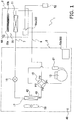
- FIG. 1 is a configuration diagram of an air conditioner 1 according to the embodiment of the present invention.
- the air conditioner 1 is a refrigeration device that can perform a cooling operation and a heating operation, and includes an indoor unit 2, an outdoor unit 3, and a liquid refrigerant communication pipe 7 for connecting the outdoor unit 3 and the indoor unit 2 to one another, and gas refrigerant communication pipe 9.
- a single component refrigerant R32 is enclosed in a refrigerant circuit of the air conditioner 1.
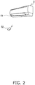
- FIG. 2 is a perspective view of the indoor unit 2.
- the indoor unit 2 includes an indoor heat exchanger 11 and an indoor fan 35.
- the indoor unit 2 comes with a remote control unit (hereinafter referred to as "remote control 52").
- the remote control 52 controls the air conditioner 1 based on operations by a user by sending/receiving signals to/from controllers built into the indoor unit 2 and the outdoor unit 3.
- the indoor heat exchanger 11 is a cross-finned tube heat exchanger including a heat transfer tube and a plurality of fins.
- the indoor heat exchanger 11 cools indoor air by functioning as a refrigerant evaporator during the cooling operation, and heats the indoor air by functioning as a refrigerant condenser during the heating operation.
- the indoor heat exchanger 11 is not limited to the cross-finned tube heat exchanger, and may be another type of heat exchanger.
- the indoor fan 35 is a cross flow fan.
- the indoor fan 35 includes a fan 35a, and an indoor fan motor unit 35b configured to rotate the fan 35a.
- the fan 35a is made of a resin material such as AS resin, and is formed into a long, thin tubular shape.
- the fan 35a is disposed such that a long axis of the fan 35a is horizontal.
- the rotation of the indoor fan 35 causes the indoor air to be sucked into the indoor unit 2 from a front surface side of the indoor unit 2, to then be heat exchanged with refrigerant in the indoor heat exchanger 11, and finally supplied as supplied air to the room.
- the indoor fan 35 can alter the amount of air supplied to the indoor heat exchanger 11 within a predetermined range.
- the outdoor unit 3 mainly includes a compressor 13, a four-way valve 15, an outdoor heat exchanger 17, an expansion valve 19, and an accumulator 21.
- the outdoor unit 3 further includes an outdoor fan 55.
- the compressor 13 is a variable capacity compressor.
- An inverter controls the speed of the compressor 13.
- only one compressor 13 is provided, but the present embodiment is not limited to this configuration, and may include two or more compressors connected to each other in parallel to accommodate the number of connected indoor units 2, for example.
- the four-way valve 15 is a valve that switches the direction of flow of the refrigerant.
- the four-way valve 15 connects a discharge side of the compressor 13 and a gas side of the outdoor heat exchanger 17 to one another, and connects an intake side of the compressor 13 (more specifically, the accumulator 21) and a side of the gas refrigerant communication pipe 9 to one another (cooling operation state: refer to the solid line that connects P1 and P4 of the four-way valve 15, and the solid line that connects P2 and P3 of the four-way valve 15 illustrated in FIG. 1 )
- the outdoor heat exchanger 17 functions as a refrigerant condenser
- the indoor heat exchanger 11 functions as a refrigerant evaporator.
- the four-way valve 15 connects the discharge side of the compressor 13 and a side of the gas refrigerant communication pipe 9 to one another, and connects the intake side of the compressor 13 and the gas side of the outdoor heat exchanger 17 to one another (heating operation state: refer to the broken line that connects P1 and P2 of the four-way valve 15, and the broken line that connects P3 and P4 of the four-way valve 15 illustrated in FIG. 1 ).
- heating operation state refer to the broken line that connects P1 and P2 of the four-way valve 15, and the broken line that connects P3 and P4 of the four-way valve 15 illustrated in FIG. 1 ).
- the indoor heat exchanger 11 functions as a refrigerant condenser
- the outdoor heat exchanger 17 functions as a refrigerant evaporator.
- the outdoor heat exchanger 17 is a cross-finned tube heat exchanger.
- the outdoor heat exchanger 17 functions as a refrigerant condenser during the cooling operation, and a refrigerant evaporator during the heating operation.
- the gas side of the outdoor heat exchanger 17 is connected to the four-way valve 15, and a liquid side of the outdoor heat exchanger 17 is connected to the expansion valve 19.
- the expansion valve 19 adjusts the pressure and flow rate and the like of the refrigerant that flows in the refrigerant circuit.
- the expansion valve 19 is disposed on a downstream side of the outdoor heat exchanger 17 in the direction the refrigerant flows in the refrigerant circuit during the cooling operation.
- the outdoor fan 55 sucks in outdoor air, and sends that air to the outdoor heat exchanger 17 to cause the air to exchange heat with refrigerant.
- the outdoor fan 55 can change the flow rate of the air that is sent to the outdoor heat exchanger 17.
- the outdoor fan 55 is, for example, a propeller fan, and is driven by a motor such as a DC fan motor.
- FIG. 3 is a block diagram showing control of the air conditioner 1.
- the controller 50 controls the operating frequency of the compressor 13, the switching action of the four-way valve 15, the opening degree of the expansion valve 19, the rotation of the indoor fan motor unit 35b, and the rotation of an air direction adjustment blade drive motor 62 on the basis of an instruction signal transmitted from the remote control 52.
- the controller 50 includes an indoor controller 50a that is built into the indoor unit 2, and an outdoor controller 50b that is built into the outdoor unit 3.
- Infrared signals are transmitted/received to/from the indoor controller 50a and the remote controller 52. Signals are wiredly transmitted/received between the indoor controller 50a and the outdoor controller 50b.
- the remote control 52 is provided with an operation switch 22, an operation change switch 24, a set temperature switch 26, an air direction control switch 61, and a set air volume switch 65.
- the set temperature switch 26 has an "up” button and a “down” button. The set temperature increases each time the "up” button is pressed, and decreases each time the "down” button is pressed.
- every operation of the air direction control switch 61 causes the controller 50 (indoor controller 50a) to control the air direction control blade drive motor 62, and alternately switch an air direction control blade 63 (see FIG. 2 ) between vertical oscillation and standstill at a desired position.
- the user can choose either one of a fixed air volume mode or an automatic air volume mode by operating the set air volume switch 65.
- the user can further choose between "weak,” “medium,” or “strong” air flow.
- the air flow rate is automatically chosen in accordance with load.
- the remote control 52 is further provided with a "powerful" selection switch 67, which is separate to the set air volume switch 65, for selecting "powerful" air flow, which is stronger than the "strong” air flow that can be selected during the fixed air volume mode.
- the air conditioner 1 is provided with an outdoor heat exchanger temperature sensor 42, an indoor temperature sensor 44, an outlet pipe temperature sensor 46, and an outside air temperature sensor 48. All of these sensors are composed of thermistors.
- the outdoor heat exchanger temperature sensor 42 is mounted to the outdoor heat exchanger 17, and is configured to detect the temperature of refrigerant that flows through a predetermined area of the outdoor heat exchanger 17.
- the indoor temperature sensor 44 is mounted to an intake port of the indoor unit 2, and is configured to detect the temperature of the indoor air.
- the outlet pipe temperature sensor 46 is mounted to a refrigerant outlet pipe of the outdoor heat exchanger 17, which functions as an evaporator during the heating operation, and is configured to detect the temperature of the refrigerant outlet pipe.
- the outside air temperature sensor 48 is configured to detect the temperature around the outdoor unit 3.
- the controller 50 controls the operation of the air conditioner 1 on the basis of values measured by these temperature sensors.
- the four-way valve 15 makes it possible to switch the cycle of refrigerant to either one of a cooling operation cycle or a heating operation cycle.
- the four-way valve 15 is set to a first state (solid line in FIG. 1 ).
- the controller 50 runs the compressor 13 such that the outdoor heat exchanger 17 acts as a condenser, and the indoor heat exchanger 11 acts as an evaporator and a vapor-compression refrigeration cycle is performed .
- High-pressure refrigerant that has been discharged from the compressor 13 is condensed through heat exchange with outside air by the outdoor heat exchanger 17.
- the refrigerant then leaves the outdoor heat exchanger 17, and is reduced in pressure when passing through the expansion valve 19, to thereby be evaporated through heat exchange with inside air by the indoor heat exchanger 11.
- the air is cooled by the indoor heat exchanger 11, and that cooled air is blown out into the room through an air outlet via the indoor fan 35.
- the refrigerant that has left the indoor heat exchanger 11 is sucked into the compressor 13 to be compressed by the compressor 13.
- the four-way valve 15 is set to a second state (broken line in FIG. 1 ).
- the controller 50 runs the compressor 13 such that the outdoor heat exchanger 17 acts as an evaporator, and the indoor heat exchanger 11 acts as a condenser and the vapor-compression refrigeration cycle is performed.
- High-pressure refrigerant that has been discharged from the compressor 13 is condensed through heat exchange with indoor air by the indoor heat exchanger 11. At this time, the air is heated by the indoor heat exchanger 11, and that heated air is blown out into the room through an air outlet via the indoor fan 35. The condensed refrigerant is then reduced in pressure when passing through the expansion valve 19, and is evaporated through heat exchange with outside air by the outdoor heat exchanger 17. The refrigerant that has left the outdoor heat exchanger 17 is sucked into the compressor 13 to be compressed by the compressor 13.
- FIG. 4 is a perspective diagram illustrating the four-way valve 15.
- FIG. 5 is a cross-sectional view illustrating the vicinity of a slide base 153 and a slide valve 155 of the four-way valve 15.
- the four-way valve 15 includes a switching valve portion 15A and a pilot-operated solenoid valve portion 15B.
- the switching valve portion 15A includes a cylinder 151, the slide base 153 (see FIG. 5 ), the slide valve 155 (see FIG. 5 ), and a pilot tube 157.
- the slide base 153 is a base that is positioned at a central portion of the cylinder 151, and facilitates sliding of the slide valve 155.
- the slide base 153 is provided with ports P2, P3, and P4, which are arranged along the axial direction of the cylinder in the stated order.
- the slide valve 155 is positioned inside the cylinder 151, and is freely slidable in the axial direction of the cylinder 151.
- the slide valve 155 has an upside-down U-shape.
- a port P1 is provided at a position that faces the port P2 of the slide base 153, and this port P1 is connected to one end of a high-pressure pipe T1.
- the pilot tube 157 communicates both ends of the cylinder 151 to the pilot-operated solenoid valve portion 15B.
- Operating the pilot-operated solenoid valve portion 15B causes the pressure at one end of the cylinder 151 to become high, and the pressure at the other end of the cylinder 151 to become low.
- the pressure difference across the both ends causes the slide valve 155 to move on the slide base 153, which causes the ports that the ports P1, P2, P3, and P4 respectively communicate with to change.
- the port P1 is connected to the high-pressure pipe T1 and thus communicates with a high-pressure side of the compressor 13, the port P1 is expressed as a high-pressure port P1. Because the port P3 is connected to a low-pressure pipe T3 and thus communicates with a low-pressure side of the compressor 13, the port P3 is expressed as a low-pressure port P3.
- the ports P2 and P4 switch between high and low pressure during the cooling operation and the heating operation, the ports P2 and P4 are connected to high-pressure pipes T2 and T4 so as to be able to withstand high pressure.
- the pilot-operated solenoid valve portion 15B includes a pilot valve unit 161 and a coil 163.
- the pilot valve unit 161 has a valve mechanism (not shown) built therein, the mechanism being able to move a movable valve with electromagnetic force in an open direction.
- the movable valve has been biased by spring force in a direction in which a valve opening closes.
- the coil 163 generates electromagnetic force for operating the valve mechanism in the open direction when electricity runs through the coil 163.
- the pilot valve unit 161 incorporates the high/low pressure, which is to be applied to the cylinder 151, from piping on the high-pressure and low-pressure sides, respectively, via pilot pipes 165 and 167.
- the slide valve 155 in the cylinder 151 is located on the left side of FIG. 5 . While the high-pressure port P1 and the port P4 are in communication with each other, and the port P2 and the low-pressure port P3 are in communication with each other, and when electricity runs through the coil 163 of the pilot-operated solenoid valve portion 15B to excite the coil 163, the pressure difference across the ends of the cylinder 151 becomes such a difference that causes the slide valve 155 to move to the right, and hence the slide valve 155 moves to the right. As a result, the high-pressure port P1 and the port P2 communicate with each other, and the low-pressure port P3 and the port P4 communicate with each other.
- the slide valve 155 is located on the left side of FIG. 5 , and the high-pressure port P1 and the port P4 are in communication with each other, and the port P2 and the low-pressure port P3 are in communication with each other.
- the pressure difference across the both ends of the cylinder 151 becomes such a difference to cause the slide valve 155 to move to the right, and hence the slide valve 155 moves to the right.
- the high-pressure port P1 and the port P2 communicate with each other
- the low-pressure port P3 and the port P4 communicate with each other.
- FIG. 6 is a flowchart showing shift to a defrosting operation that includes impulse noise masking control.
- FIG. 7A is a time chart showing shift to the defrosting operation that includes the impulse noise masking control.
- FIG. 7B is a time chart showing shift to a defrosting operation that does not include the impulse noise masking control. Note that the impulse noise masking control corresponds to "first control" cited in claim 1.
- Step S1 the controller 50 determines whether or not a condition for causing the air conditioner 1 to shift to the defrosting operation is satisfied.
- the controller 50 proceeds to Step S2: otherwise, the controller 50 continues the process of determination.
- Step S2 the controller 50 reduces the operating frequency of the compressor 13 to Fd1 (see FIG. 7A ), and proceeds to Step S3.
- Step S3 the controller 50 operates the compressor 13 for a predetermined period of time while maintaining the operating frequency at Fd1 (see FIG. 7A ), and then proceeds to Step S4.
- Step S4 the controller 50 determines whether or not the indoor fan 35 is rotating at a high speed.
- “rotating at a high speed” is determined in accordance with air flow rate set by the remote control 52, and, for example, corresponds to a state in which the indoor fan 35 rotates while the air flow is “strong,” assuming that the strength of air flow has been selected from the options “weak,” “medium,” and “strong.”
- the controller 50 determines that the indoor fan 35 is rotating at a high speed
- the controller 50 proceeds to Step S5.
- the controller 50 determines that the indoor fan 35 is not rotating at a high speed
- the controller 50 proceeds to Step S14.
- Step S5 the controller 50 maintains rotation of the indoor fan 35 (see FIG. 7A ).
- Step S6 the controller 50 switches the refrigerant cycle from the heating cycle to the cooling cycle by using the four-way valve 15 (see FIG. 7A ).
- the impulse noise that is generated when the four-way valve 15 performs the switching action is transmitted to the indoor unit 2 through pipes.
- the indoor fan 35 is rotating at a high speed, the impulse noise is drowned out by the noise of the indoor fan 35.
- Step S7 the controller 50 performs the defrosting operation.
- the defrosting operation is performed by stopping the outdoor fan 55 while still running the compressor 13.
- Step S8 after a predetermined period of time has passed after the controller 50 switches the refrigerant cycle to the cooling cycle by using the four-way valve 15, the controller 50 stops the indoor fan 35.
- Step S9 the controller 50 then determines whether or not a condition for causing the air conditioner 1 to end the defrosting operation is satisfied.
- the controller 50 determines that the condition for causing the air conditioner 1 to end the defrosting operation is satisfied, the defrosting operation is ended: otherwise, the controller 50 continues the process of determination.
- controlling the shift to the defrosting operation that includes the impulse noise masking control causes the impulse noise generated when the four-way valve 15 performs the switching action to be drowned out by the noise of the indoor fan 35. Therefore, the user can be prevented from feeling uncomfortable due to a strange noise.
- Step S14 the controller 50 stops the indoor fan 35 and the compressor 13 (see FIG. 7B ).
- Step S15 the controller 50 performs a pressure equalization operation while stopping the compressor 13 for a predetermined period of time (see FIG. 7B ).
- the "pressure equalization operation” refers to an operation of reducing the differential pressure in the refrigerant circuit while continuing to run the outdoor fan 55 and sending air to the outdoor heat exchanger 17.
- Step S16 the controller 50 switches the refrigerant cycle from the heating cycle to the cooling cycle by using the four-way valve 15 (see FIG. 7B ). Because the pressure equalization operation is started in advance to reduce the differential pressure in the refrigerant circuit, the impulse noise decreases, and the user can be prevented from feeling uncomfortable due to a strange noise.
- Step S17 the controller 50 ends the pressure equalization operation (see FIG. 7B ).
- Step S18 the controller 50 activates the compressor 13 to start the defrosting operation (see FIG. 7B ). After that, the controller 50 jumps to Step S9.
- Step S9 the controller 50 determines whether or not the condition for causing the air conditioner 1 to end the defrosting operation is satisfied.
- the controller 50 determines that the condition for causing the air conditioner 1 to end the defrosting operation is satisfied, the defrosting operation ends: otherwise the controller 50 continues the process of determination.
- the controller 50 selects, depending on whether or not the indoor fan 35 is rotating at a high speed, either performing the impulse noise masking control to shift to the defrosting operation, or performing the pressure equalization operation to shift to the defrosting operation.
- the noise of the indoor fan 35 drowns out the impulse noise that occurs when the four-way valve 15 performs the switching action, and the user can be prevented from feeling uncomfortable due to a strange noise.
- the impulse noise can be realiably masked by the noise of the indoor fan 35.
- the impulse noise that occurs when the four-way valve 15 performs the switching action can be drowned out, and the user can be prevented from feeling uncomfortable due to a strange noise.
- the air conditioner 1 as a method of preventing the user from noticing the impulse noise that occurs when the four-way valve 15 performs the switching action, it is possible to selectively use the impulse noise masking control and the pressure equalization operation based on the speed of the indoor fan 35 before the switching action. Therefore, compared to a conventional method of merely selecting the pressure equalization operation, there are more opportunities to increase the heating operation operating rate.
- the controller 50 reduces the operating frequency of the compressor 13 in advance when performing the impulse noise masking control while continuing to run the compressor 13, to thereby somewhat reduce the differential pressure in the refrigerant circuit. Therefore, the impulse noise that occurs when the four-way valve 15 performs the switching action also reduces by the amount the differential pressure is reduced, and the impulse noise can be reliably drowned out when the impulse noise is masked by the noise of the indoor fan 35.
- whether to perform the impulse noise masking control to shift to the defrosting operation, or perform the pressure equalization operation to shift to the defrosting operation is selected depending on whether or not the speed of the indoor fan 35 is high.
- both the pressure equalization operation and the impulse noise masking control may be performed (this corresponds to "second control" in claim 3).
- the pressure equalization operation causes the differential pressure in the refrigerant circuit to decrease, and hence the impulse noise that occurs when the four-way valve 15 performs the switching action is reduced.
- the noise of the indoor fan 35 can mask and reliably drown out the impulse noise, and the user can be prevented from feeling uncomfortable due to a strange noise.
Landscapes
- Engineering & Computer Science (AREA)
- Mechanical Engineering (AREA)
- General Engineering & Computer Science (AREA)
- Chemical & Material Sciences (AREA)
- Combustion & Propulsion (AREA)
- Physics & Mathematics (AREA)
- Fluid Mechanics (AREA)
- Thermal Sciences (AREA)
- Air Conditioning Control Device (AREA)
- Compression-Type Refrigeration Machines With Reversible Cycles (AREA)
Abstract
Description
- The present invention relates to an air conditioner.
- During a heating operation of an air conditioner, in order for the air conditioner to shift to a defrosting operation, the air conditioner performs an operation of substantially reducing differential pressure to reduce impulse noise when a four-way valve switches from a heating cycle to a cooling cycle, and then shifts to the defrosting operation by switching the four-way valve.
- For example, in a control device for a refrigeration cycle disclosed in Patent Literature 1 (
JP-A No. H10-253205 - However, in the above-mentioned control, the compressor is operated at the low-speed by reducing the operating frequency in order to reduce the difference between the high pressure and the low pressure in the refrigeration cycle, and hence heating capacity during that low-speed operation decreases.
- An object of the present invention is to provide an air conditioner that is capable of dealing with impact noise that occurs when a four-way valve is switched, and reducing heating capacity degredation before the air conditioner shifts to a defrosting operation.
- An air conditioner according to a first aspect of the present invention includes a refrigerant circuit formed of a compressor, an outdoor heat exchanger, an expansion mechanism, and an indoor heat exchanger connected to one another in the stated order, in which the air conditioner switches from a heating cycle in which the outdoor heat exchanger functions as an evaporator to a cooling cycle in which the outdoor heat exchanger functions as a condenser, to thereby perform a defrosting operation of melting frost that has adhered to the outdoor heat exchanger. The air conditioner includes a four-way valve, an indoor fan, and a controller. The four-way valve performs a switching action of switching between the heating cycle and the cooling cycle in the refrigerant circuit. The indoor fan sends air to the indoor heat exchanger. The controller controls operations of the four-way valve and the indoor fan. The controller also performs a first control of putting the air conditioner into a state in which the indoor fan is running when the four-way valve performs the switching action.
- In the air conditioner according to this aspect, although a user is used to hearing the sound of the indoor fan that usually occurs while the indoor unit is running, the sound of impact that occurs when the four-way valve performs the switching action is shocking and strange to the user. To counteract this, the impulse noise that occurs when the four-way valve performs the switching action is drowned out by the noise of the indoor fan if the indoor fan runs when the four-way valve performs the switching action. Therefore, the user can be prevented from feeling uncomfortable due to the strange noise that occurs. In addition, there is no need to reduce the operating frequency of the compressor before the air conditioner shifts to the defrosting operation, and so a reduction in heating operation capability can be prevented.
- An air conditioner according to a second aspect of the present invention is the air conditioner according to the first aspect of the present invention, in which the controller performs the first control while continuing to run the compressor.
- In the air conditioner according to this aspect, there is no need to perform pressure equalization control by stopping the compressor and reducing the differential pressure in the refrigerant circuit before the defrosting operation, which saves pressure equalization time. Therefore, the heating operation operating ratio (= net heating operation time/<net heating operation time + defrosting operation time>) increases by the amount of time saved.
- An air conditioner according to a third aspect of the present invention is the air conditioner according to the first aspect of the present invention, in which, even if pressure equalization control of stopping the compressor and reducing the differential pressure in the refrigerant circuit before the defrosting operation is performed, the controller performs a second control of putting the air conditioner into a state in which the indoor fan is running when the four-way valve performs the switching action during the pressure equalization control.
- In the air conditioner according to this aspect, because the differential pressure in the refrigerant circuit decreases due to the pressure eualization control, the impulse noise that occurs when the four-way valve performs the switching action is reduced. In addition, the noise of the indoor fan masks the impulse noise to drown out the impulse noise, which can prevent the user from feeling uncomfortable due to a strange noise.
- An air conditioner according to a fourth aspect of the present invention is the air conditioner according to any one of the first to third aspects of the present invention, in which the controller continues to run the indoor fan for a period spanning from before the four-way valve performs the switching action to until the switching action ends.
- In the air conditioner according to this aspect, because the indoor fan continues to run before and after the four-way valve performs the switching action, the impulse noise can reliably be masked by the noise of the indoor fan. As a result, the impulse noise that occurs when the four-way valve performs the switching action can be drowned out, and the user can be prevented from feeling uncomfortable due to a strange noise.
- An air conditioner according to a fifth aspect of the present invention is the air conditioner according to the first aspect of the present invention, in which the controller performs the first control without stopping the compressor when the speed of the indoor fan before the four-way valve performs the switching action is equal to or more than a predetermined speed. In addition, the controller performs the pressure equalization control of stopping the compressor and the indoor fan, and reducing the differential pressure in the refrigerant circuit when the speed of the indoor fan before the four-way valve performs the switching action is less than the predetermined speed.
- In the air conditioner according to this aspect, as a method of preventing the user from noticing the impulse noise the occurs when the four-way valve performs the switching action, the first control and the pressure equalization control can be selectively used depending on the speed of the indoor fan before the switching action is performed. Therefore, compared to a conventional method of only selecting the pressure equalization control, there are more chances to increase the heating operation operating ratio.
- An air conditioner according to a sixth aspect of the present invention is the air conditioner according to the second aspect of the present invention, in which the controller reduces the operating frequency of the compressor before the four-way valve performs the switching action.
- In the air conditioner according to this aspect, the controller reduces the operating frequency of the compressor in advance when performing the first control while continuing to run the compressor, to thereby somewhat reduce the differential pressure in the refrigerant circuit. Therefore, the impulse noise that occurs when the four-way valve performs the switching action also reduces by the amount the differential pressure is reduced, and can be reliably drowned out by being masked by the noise of the indoor fan.
- In the air conditioner according to the first aspect of the present invention, because the indoor fan runs when the four-way valve performs the switching action, the noise of the indoor fan drowns out the impulse noise that occurs when the four-way valve performs the switching action, and the user can be prevented from feeling uncomfortable due to a strange noise. In addition, because there is no need to reduce the operating frequency of the compressor before shifting to the defrosting operation, reduction of the heating operation capacity can be prevented.
- In the air conditioner according to the second aspect of the present invention, there is no need to perform the pressure equalization control of stopping the compressor and reducing the differential pressure in the refrigerant circuit before the defrosting operation, which saves the time required to equalize pressure. Therefore, the heating operation operating ratio (= net heating operation time/<net heating operation time + defrosting operation time>) increases by the amount of time saved.
- In the air conditioner according to the third aspect of the present invention, because the differential pressure in the refrigerant circuit reduces due to the pressure equalization control, the impulse noise the occurs when the four-way valve performs the switching action is reduced. In addition, the noise of the indoor fan masks the impulse noise to drown out the impulse noise, which prevents the user from feeling uncomfortable due to a strange noise.
- In the air conditioner according to the fourth aspect of the present invention, because the indoor fan continues to run before and after the four-way valve performs the switching action, the impulse noise can reliably be masked by the noise of the indoor fan. As a result, the impulse noise that occurs when the four-way valve performs the switching action can be drowned out, and the user can be prevented from feeling uncomfortable due to a strange noise.
- In the air conditioner according to the fifth aspect of the present invention, as a method of preventing the user from noticing the impulse noise the occurs when the four-way valve performs the switching action, the first control and the pressure equalization control can be selectively used depending on the speed of the indoor fan before the switching action is performed. Therefore, compared to a conventional method of only selecting the pressure equalization control, there are more chances to increase the heating operation operating ratio.
- In the air conditioner according to the sixth aspect of the present invention, the controller reduces the operating frequency of the compressor in advance when performing the first control while continuing to run the compressor, to thereby somewhat reduce the differential pressure in the refrigerant circuit. Therefore, the impulse noise that occurs when the four-way valve performs the switching action also reduces by the amount the differential pressure is reduced, and the impulse noise can be reliably drowned out when masked by the noise of the indoor fan.
-
-
FIG. 1 is a configuration diagram illustrating an air conditioner according to an embodiment of the present invention. -
FIG. 2 is a perspective diagram illustrating an indoor unit. -
FIG. 3 is a block diagram showing control of the air conditioner. -
FIG. 4 is a perspective diagram illustrating a four-way valve. -
FIG. 5 is a cross-sectional view illustrating the vicinity of a slide base and a slide valve of the four-way valve. -
FIG. 6 is a flowchart showing shift to a defrosting operation that includes impulse noise masking control. -
FIG. 7A is a time chart showing shift to the defrosting operation that includes the impulse noise masking control. -
FIG. 7B is a time chart showing shift to a defrosting operation that does not include the impulse noise masking control. - An embodiment of the present invention is described below with reference to the drawings. The embodiment described below is merely a specific example of the present invention and is not intended to limit the technical scope of the present invention.
-
FIG. 1 is a configuration diagram of anair conditioner 1 according to the embodiment of the present invention. InFIG. 1 , theair conditioner 1 is a refrigeration device that can perform a cooling operation and a heating operation, and includes anindoor unit 2, anoutdoor unit 3, and a liquidrefrigerant communication pipe 7 for connecting theoutdoor unit 3 and theindoor unit 2 to one another, and gasrefrigerant communication pipe 9. A single component refrigerant R32 is enclosed in a refrigerant circuit of theair conditioner 1. -
FIG. 2 is a perspective view of theindoor unit 2. InFIG. 1 andFIG. 2 , theindoor unit 2 includes anindoor heat exchanger 11 and anindoor fan 35. In addition, theindoor unit 2 comes with a remote control unit (hereinafter referred to as "remote control 52"). Theremote control 52 controls theair conditioner 1 based on operations by a user by sending/receiving signals to/from controllers built into theindoor unit 2 and theoutdoor unit 3. - The
indoor heat exchanger 11 is a cross-finned tube heat exchanger including a heat transfer tube and a plurality of fins. Theindoor heat exchanger 11 cools indoor air by functioning as a refrigerant evaporator during the cooling operation, and heats the indoor air by functioning as a refrigerant condenser during the heating operation. - The
indoor heat exchanger 11 is not limited to the cross-finned tube heat exchanger, and may be another type of heat exchanger. - The
indoor fan 35 is a cross flow fan. Theindoor fan 35 includes afan 35a, and an indoorfan motor unit 35b configured to rotate thefan 35a. Thefan 35a is made of a resin material such as AS resin, and is formed into a long, thin tubular shape. Thefan 35a is disposed such that a long axis of thefan 35a is horizontal. - The rotation of the
indoor fan 35 causes the indoor air to be sucked into theindoor unit 2 from a front surface side of theindoor unit 2, to then be heat exchanged with refrigerant in theindoor heat exchanger 11, and finally supplied as supplied air to the room. In addition, theindoor fan 35 can alter the amount of air supplied to theindoor heat exchanger 11 within a predetermined range. - In
FIG. 1 , theoutdoor unit 3 mainly includes acompressor 13, a four-way valve 15, anoutdoor heat exchanger 17, anexpansion valve 19, and anaccumulator 21. Theoutdoor unit 3 further includes anoutdoor fan 55. - The
compressor 13 is a variable capacity compressor. An inverter controls the speed of thecompressor 13. In the present embodiment, only onecompressor 13 is provided, but the present embodiment is not limited to this configuration, and may include two or more compressors connected to each other in parallel to accommodate the number of connectedindoor units 2, for example. - The four-
way valve 15 is a valve that switches the direction of flow of the refrigerant. During the cooling operation, the four-way valve 15 connects a discharge side of thecompressor 13 and a gas side of theoutdoor heat exchanger 17 to one another, and connects an intake side of the compressor 13 (more specifically, the accumulator 21) and a side of the gasrefrigerant communication pipe 9 to one another (cooling operation state: refer to the solid line that connects P1 and P4 of the four-way valve 15, and the solid line that connects P2 and P3 of the four-way valve 15 illustrated inFIG. 1 ) As a result, theoutdoor heat exchanger 17 functions as a refrigerant condenser, and theindoor heat exchanger 11 functions as a refrigerant evaporator. - During the heating operation, the four-
way valve 15 connects the discharge side of thecompressor 13 and a side of the gasrefrigerant communication pipe 9 to one another, and connects the intake side of thecompressor 13 and the gas side of theoutdoor heat exchanger 17 to one another (heating operation state: refer to the broken line that connects P1 and P2 of the four-way valve 15, and the broken line that connects P3 and P4 of the four-way valve 15 illustrated inFIG. 1 ). As a result, theindoor heat exchanger 11 functions as a refrigerant condenser, and theoutdoor heat exchanger 17 functions as a refrigerant evaporator. - The
outdoor heat exchanger 17 is a cross-finned tube heat exchanger. Theoutdoor heat exchanger 17 functions as a refrigerant condenser during the cooling operation, and a refrigerant evaporator during the heating operation. The gas side of theoutdoor heat exchanger 17 is connected to the four-way valve 15, and a liquid side of theoutdoor heat exchanger 17 is connected to theexpansion valve 19. - The
expansion valve 19 adjusts the pressure and flow rate and the like of the refrigerant that flows in the refrigerant circuit. Theexpansion valve 19 is disposed on a downstream side of theoutdoor heat exchanger 17 in the direction the refrigerant flows in the refrigerant circuit during the cooling operation. - The
outdoor fan 55 sucks in outdoor air, and sends that air to theoutdoor heat exchanger 17 to cause the air to exchange heat with refrigerant. Theoutdoor fan 55 can change the flow rate of the air that is sent to theoutdoor heat exchanger 17. Theoutdoor fan 55 is, for example, a propeller fan, and is driven by a motor such as a DC fan motor. -
FIG. 3 is a block diagram showing control of theair conditioner 1. InFIG. 3 , thecontroller 50 controls the operating frequency of thecompressor 13, the switching action of the four-way valve 15, the opening degree of theexpansion valve 19, the rotation of the indoorfan motor unit 35b, and the rotation of an air direction adjustmentblade drive motor 62 on the basis of an instruction signal transmitted from theremote control 52. - As illustrated in
FIG. 1 , thecontroller 50 includes anindoor controller 50a that is built into theindoor unit 2, and anoutdoor controller 50b that is built into theoutdoor unit 3. Infrared signals are transmitted/received to/from theindoor controller 50a and theremote controller 52. Signals are wiredly transmitted/received between theindoor controller 50a and theoutdoor controller 50b. - The
remote control 52 is provided with anoperation switch 22, anoperation change switch 24, aset temperature switch 26, an airdirection control switch 61, and a setair volume switch 65. - Each time the
operation switch 22 is operated, theair conditioner 1 alternately switches between operating and stopping. Each operation of theoperation change switch 24 switches the operation of theair conditioner 1 in the order of automatic→cooling→ dehumidification→heating. The settemperature switch 26 has an "up" button and a "down" button. The set temperature increases each time the "up" button is pressed, and decreases each time the "down" button is pressed. - In addition, every operation of the air
direction control switch 61 causes the controller 50 (indoor controller 50a) to control the air direction controlblade drive motor 62, and alternately switch an air direction control blade 63 (seeFIG. 2 ) between vertical oscillation and standstill at a desired position. - In addition, the user can choose either one of a fixed air volume mode or an automatic air volume mode by operating the set
air volume switch 65. When the user has chosen the fixed air volume mode, the user can further choose between "weak," "medium," or "strong" air flow. In contrast, when the user has chosen the automatic air volume mode, the air flow rate is automatically chosen in accordance with load. - In this embodiment, the
remote control 52 is further provided with a "powerful"selection switch 67, which is separate to the setair volume switch 65, for selecting "powerful" air flow, which is stronger than the "strong" air flow that can be selected during the fixed air volume mode. - The
air conditioner 1 is provided with an outdoor heatexchanger temperature sensor 42, anindoor temperature sensor 44, an outletpipe temperature sensor 46, and an outsideair temperature sensor 48. All of these sensors are composed of thermistors. The outdoor heatexchanger temperature sensor 42 is mounted to theoutdoor heat exchanger 17, and is configured to detect the temperature of refrigerant that flows through a predetermined area of theoutdoor heat exchanger 17. Theindoor temperature sensor 44 is mounted to an intake port of theindoor unit 2, and is configured to detect the temperature of the indoor air. The outletpipe temperature sensor 46 is mounted to a refrigerant outlet pipe of theoutdoor heat exchanger 17, which functions as an evaporator during the heating operation, and is configured to detect the temperature of the refrigerant outlet pipe. The outsideair temperature sensor 48 is configured to detect the temperature around theoutdoor unit 3. Thecontroller 50 controls the operation of theair conditioner 1 on the basis of values measured by these temperature sensors. - In the
air conditioner 1, the four-way valve 15 makes it possible to switch the cycle of refrigerant to either one of a cooling operation cycle or a heating operation cycle. - In the cooling operation, the four-
way valve 15 is set to a first state (solid line inFIG. 1 ). In this state, thecontroller 50 runs thecompressor 13 such that theoutdoor heat exchanger 17 acts as a condenser, and theindoor heat exchanger 11 acts as an evaporator and a vapor-compression refrigeration cycle is performed . - High-pressure refrigerant that has been discharged from the
compressor 13 is condensed through heat exchange with outside air by theoutdoor heat exchanger 17. The refrigerant then leaves theoutdoor heat exchanger 17, and is reduced in pressure when passing through theexpansion valve 19, to thereby be evaporated through heat exchange with inside air by theindoor heat exchanger 11. At this time, the air is cooled by theindoor heat exchanger 11, and that cooled air is blown out into the room through an air outlet via theindoor fan 35. The refrigerant that has left theindoor heat exchanger 11 is sucked into thecompressor 13 to be compressed by thecompressor 13. - In the heating operation, the four-
way valve 15 is set to a second state (broken line inFIG. 1 ). In this state, thecontroller 50 runs thecompressor 13 such that theoutdoor heat exchanger 17 acts as an evaporator, and theindoor heat exchanger 11 acts as a condenser and the vapor-compression refrigeration cycle is performed.. - High-pressure refrigerant that has been discharged from the
compressor 13 is condensed through heat exchange with indoor air by theindoor heat exchanger 11. At this time, the air is heated by theindoor heat exchanger 11, and that heated air is blown out into the room through an air outlet via theindoor fan 35. The condensed refrigerant is then reduced in pressure when passing through theexpansion valve 19, and is evaporated through heat exchange with outside air by theoutdoor heat exchanger 17. The refrigerant that has left theoutdoor heat exchanger 17 is sucked into thecompressor 13 to be compressed by thecompressor 13. -
FIG. 4 is a perspective diagram illustrating the four-way valve 15.FIG. 5 is a cross-sectional view illustrating the vicinity of aslide base 153 and aslide valve 155 of the four-way valve 15. - In
FIG. 4 andFIG. 5 , the four-way valve 15 includes a switchingvalve portion 15A and a pilot-operatedsolenoid valve portion 15B. The switchingvalve portion 15A includes acylinder 151, the slide base 153 (seeFIG. 5 ), the slide valve 155 (seeFIG. 5 ), and apilot tube 157. - The
slide base 153 is a base that is positioned at a central portion of thecylinder 151, and facilitates sliding of theslide valve 155. Theslide base 153 is provided with ports P2, P3, and P4, which are arranged along the axial direction of the cylinder in the stated order. - The
slide valve 155 is positioned inside thecylinder 151, and is freely slidable in the axial direction of thecylinder 151. In addition, theslide valve 155 has an upside-down U-shape. - In the
cylinder 151, a port P1 is provided at a position that faces the port P2 of theslide base 153, and this port P1 is connected to one end of a high-pressure pipe T1. - The
pilot tube 157 communicates both ends of thecylinder 151 to the pilot-operatedsolenoid valve portion 15B. Operating the pilot-operatedsolenoid valve portion 15B causes the pressure at one end of thecylinder 151 to become high, and the pressure at the other end of thecylinder 151 to become low. The pressure difference across the both ends causes theslide valve 155 to move on theslide base 153, which causes the ports that the ports P1, P2, P3, and P4 respectively communicate with to change. - Because the port P1 is connected to the high-pressure pipe T1 and thus communicates with a high-pressure side of the
compressor 13, the port P1 is expressed as a high-pressure port P1. Because the port P3 is connected to a low-pressure pipe T3 and thus communicates with a low-pressure side of thecompressor 13, the port P3 is expressed as a low-pressure port P3. - Because the ports P2 and P4 switch between high and low pressure during the cooling operation and the heating operation, the ports P2 and P4 are connected to high-pressure pipes T2 and T4 so as to be able to withstand high pressure.
- The pilot-operated
solenoid valve portion 15B includes apilot valve unit 161 and acoil 163. Thepilot valve unit 161 has a valve mechanism (not shown) built therein, the mechanism being able to move a movable valve with electromagnetic force in an open direction. The movable valve has been biased by spring force in a direction in which a valve opening closes. Thecoil 163 generates electromagnetic force for operating the valve mechanism in the open direction when electricity runs through thecoil 163. - The
pilot valve unit 161 incorporates the high/low pressure, which is to be applied to thecylinder 151, from piping on the high-pressure and low-pressure sides, respectively, viapilot pipes - In the four-
way valve 15 with the above-described configuration, theslide valve 155 in thecylinder 151 is located on the left side ofFIG. 5 . While the high-pressure port P1 and the port P4 are in communication with each other, and the port P2 and the low-pressure port P3 are in communication with each other, and when electricity runs through thecoil 163 of the pilot-operatedsolenoid valve portion 15B to excite thecoil 163, the pressure difference across the ends of thecylinder 151 becomes such a difference that causes theslide valve 155 to move to the right, and hence theslide valve 155 moves to the right. As a result, the high-pressure port P1 and the port P2 communicate with each other, and the low-pressure port P3 and the port P4 communicate with each other. - In contrast, when the four-
way valve 15 is switched in the opposite direction, and the electricity running through thecoil 163 of the pilot-operatedsolenoid valve portion 15B is stopped to stop excitation of thecoil 163, the pressure difference across the ends of thecylinder 151 becomes such a difference that causes theslide valve 155 to move to the left, and hence theslide valve 155 moves to the left. As a result, the high-pressure port P1 and the port P4 communicate with each other, and the port P2 and the low-pressure port P3 communicate with each other. - For example, during the heating operation, because electricity does not run through the
coil 163 of the pilot-operatedsolenoid valve portion 15B and hence thecoil 163 is not excited, theslide valve 155 is located on the left side ofFIG. 5 , and the high-pressure port P1 and the port P4 are in communication with each other, and the port P2 and the low-pressure port P3 are in communication with each other. At this time, when there is an instruction to shift to the defrosting operation, the pressure difference across the both ends of thecylinder 151 becomes such a difference to cause theslide valve 155 to move to the right, and hence theslide valve 155 moves to the right. As a result, the high-pressure port P1 and the port P2 communicate with each other, and the low-pressure port P3 and the port P4 communicate with each other. - As a result, high pressure from the high-pressure port P1 suddenly acts on the port P2, which has had a low pressure up until that point, and this sudden impact causes the impulse noise to be generated.
-
FIG. 6 is a flowchart showing shift to a defrosting operation that includes impulse noise masking control.FIG. 7A is a time chart showing shift to the defrosting operation that includes the impulse noise masking control.FIG. 7B is a time chart showing shift to a defrosting operation that does not include the impulse noise masking control. Note that the impulse noise masking control corresponds to "first control" cited inclaim 1. - In
FIGS. 6 ,7A and7B , in Step S1, thecontroller 50 determines whether or not a condition for causing theair conditioner 1 to shift to the defrosting operation is satisfied. When thecontroller 50 determines that the condition for causing theair conditioner 1 to shift to the defrosting operation is satisfied, thecontroller 50 proceeds to Step S2: otherwise, thecontroller 50 continues the process of determination. - Next, in Step S2, the
controller 50 reduces the operating frequency of thecompressor 13 to Fd1 (seeFIG. 7A ), and proceeds to Step S3. - Then, in Step S3, the
controller 50 operates thecompressor 13 for a predetermined period of time while maintaining the operating frequency at Fd1 (seeFIG. 7A ), and then proceeds to Step S4. - Next, in Step S4, the
controller 50 determines whether or not theindoor fan 35 is rotating at a high speed. Here, "rotating at a high speed" is determined in accordance with air flow rate set by theremote control 52, and, for example, corresponds to a state in which theindoor fan 35 rotates while the air flow is "strong," assuming that the strength of air flow has been selected from the options "weak," "medium," and "strong." In addition, in this embodiment, it is also determined that theindoor fan 35 is rotating at a high speed when the air flow is set to "powerful" by the "powerful"selection switch 67, which is an option other than "strong." When thecontroller 50 determines that theindoor fan 35 is rotating at a high speed, thecontroller 50 proceeds to Step S5. When thecontroller 50 determines that theindoor fan 35 is not rotating at a high speed, thecontroller 50 proceeds to Step S14. - Next, in Step S5, the
controller 50 maintains rotation of the indoor fan 35 (seeFIG. 7A ). - Then, in Step S6, the
controller 50 switches the refrigerant cycle from the heating cycle to the cooling cycle by using the four-way valve 15 (seeFIG. 7A ). At this time, the impulse noise that is generated when the four-way valve 15 performs the switching action is transmitted to theindoor unit 2 through pipes. However, because theindoor fan 35 is rotating at a high speed, the impulse noise is drowned out by the noise of theindoor fan 35. - Next, in Step S7, the
controller 50 performs the defrosting operation. The defrosting operation is performed by stopping theoutdoor fan 55 while still running thecompressor 13. - Then, in Step S8, after a predetermined period of time has passed after the
controller 50 switches the refrigerant cycle to the cooling cycle by using the four-way valve 15, thecontroller 50 stops theindoor fan 35. - In Step S9, the
controller 50 then determines whether or not a condition for causing theair conditioner 1 to end the defrosting operation is satisfied. When thecontroller 50 determines that the condition for causing theair conditioner 1 to end the defrosting operation is satisfied, the defrosting operation is ended: otherwise, thecontroller 50 continues the process of determination. - As described above, controlling the shift to the defrosting operation that includes the impulse noise masking control causes the impulse noise generated when the four-
way valve 15 performs the switching action to be drowned out by the noise of theindoor fan 35. Therefore, the user can be prevented from feeling uncomfortable due to a strange noise. - In contrast, when the
controller 50 proceeds to Step S14 after the determination in Step S4, in Step S14, thecontroller 50 stops theindoor fan 35 and the compressor 13 (seeFIG. 7B ). - Next, in Step S15, the
controller 50 performs a pressure equalization operation while stopping thecompressor 13 for a predetermined period of time (seeFIG. 7B ). The "pressure equalization operation" refers to an operation of reducing the differential pressure in the refrigerant circuit while continuing to run theoutdoor fan 55 and sending air to theoutdoor heat exchanger 17. - Then, in Step S16, the
controller 50 switches the refrigerant cycle from the heating cycle to the cooling cycle by using the four-way valve 15 (seeFIG. 7B ). Because the pressure equalization operation is started in advance to reduce the differential pressure in the refrigerant circuit, the impulse noise decreases, and the user can be prevented from feeling uncomfortable due to a strange noise. - Next, in Step S17, the
controller 50 ends the pressure equalization operation (seeFIG. 7B ). - Then, in Step S18, the
controller 50 activates thecompressor 13 to start the defrosting operation (seeFIG. 7B ). After that, thecontroller 50 jumps to Step S9. - Then, in Step S9, the
controller 50 determines whether or not the condition for causing theair conditioner 1 to end the defrosting operation is satisfied. When thecontroller 50 determines that the condition for causing theair conditioner 1 to end the defrosting operation is satisfied, the defrosting operation ends: otherwise thecontroller 50 continues the process of determination. - As described above, after the
controller 50 has determined that the condition for causing theair conditioner 1 to shift to the defrosting operation is satisfied, thecontroller 50 selects, depending on whether or not theindoor fan 35 is rotating at a high speed, either performing the impulse noise masking control to shift to the defrosting operation, or performing the pressure equalization operation to shift to the defrosting operation. - No matter if the former or the latter is selected, the user can be prevented from feeling uncomfortable due to a strange noise.
- In the
air conditioner 1, because theindoor fan 35 is running when the four-way valve 15 performs the switching action, the noise of theindoor fan 35 drowns out the impulse noise that occurs when the four-way valve 15 performs the switching action, and the user can be prevented from feeling uncomfortable due to a strange noise. - In addition, because there is no need to reduce the operating frequency of the compressor before shifting to the defrosting operation, a reduction in the heating operation ability can be prevented.
- In the
air conditioner 1, theindoor fan 35 is configured to run when the four-way valve 15 performs the switching action. Therefore, there is no need to perform the pressure equalization operation of stopping thecompressor 13 and reducing the differential pressure in the refrigerant circuit before the defrosting operation, which reduces the time taken to perform the pressure equalization control. As a result, the heating operation operating ratio (= net heating operation time/<net heating operation time + defrosting operation time>) increases. - In the
air conditioner 1, because theindoor fan 35 continues to run before and after the four-way valve 15 performs the switching action, the impulse noise can be realiably masked by the noise of theindoor fan 35. As a result, the impulse noise that occurs when the four-way valve 15 performs the switching action can be drowned out, and the user can be prevented from feeling uncomfortable due to a strange noise. - In the
air conditioner 1, as a method of preventing the user from noticing the impulse noise that occurs when the four-way valve 15 performs the switching action, it is possible to selectively use the impulse noise masking control and the pressure equalization operation based on the speed of theindoor fan 35 before the switching action. Therefore, compared to a conventional method of merely selecting the pressure equalization operation, there are more opportunities to increase the heating operation operating rate. - In the
air conditioner 1, thecontroller 50 reduces the operating frequency of thecompressor 13 in advance when performing the impulse noise masking control while continuing to run thecompressor 13, to thereby somewhat reduce the differential pressure in the refrigerant circuit. Therefore, the impulse noise that occurs when the four-way valve 15 performs the switching action also reduces by the amount the differential pressure is reduced, and the impulse noise can be reliably drowned out when the impulse noise is masked by the noise of theindoor fan 35. - In the above-described embodiment, whether to perform the impulse noise masking control to shift to the defrosting operation, or perform the pressure equalization operation to shift to the defrosting operation is selected depending on whether or not the speed of the
indoor fan 35 is high. - However, both the pressure equalization operation and the impulse noise masking control may be performed (this corresponds to "second control" in claim 3). In this case, the pressure equalization operation causes the differential pressure in the refrigerant circuit to decrease, and hence the impulse noise that occurs when the four-
way valve 15 performs the switching action is reduced. In addition, the noise of theindoor fan 35 can mask and reliably drown out the impulse noise, and the user can be prevented from feeling uncomfortable due to a strange noise. -
- 1
- air conditioner
- 11
- indoor heat exchanger
- 13
- compressor
- 15
- four-way valve
- 17
- outdoor heat exchanger
- 19
- expansion valve (expansion mechanism)
- 35
- indoor fan
- 50
- controller
- <
Patent Literature 1> Japanese Patent Application PublicationH10-253205
Claims (6)
- An air conditioner comprising a refrigerant circuit formed of a compressor (13), an outdoor heat exchanger (17), an expansion mechanism (19), and an indoor heat exchanger (11) connected to one another in the stated order, the air conditioner configured to perform a defrosting operation of melting frost that has adhered to the outdoor heat exchanger (17) by switching from a heating cycle in which the outdoor heat exchanger (17) functions as an evaporator to a cooling cycle in which the outdoor heat exchanger (17) functions as a condenser, the air conditioner comprising:a four-way valve (15) configured to perform a switching action of switching between the heating cycle and the cooling cycle in the refrigerant circuit;an indoor fan (35) configured to send air to the indoor heat exchanger (11); anda controller (50) configured to control operations of the four-way valve (15) and operations of the indoor fan (35), the controller (50) being configured to perform a first control of putting the air conditioner into a state in which the indoor fan (35) is running when the four-way valve (15) performs the switching action.
- The air conditioner according to claim 1, wherein
the controller (50) performs the first control while continuing to run the compressor (13). - The air conditioner according to claim 1, wherein
even if pressure equalization control of stopping the compressor (13) and reducing differential pressure in the refrigerant circuit is performed before the defrosting operation, the controller (50) performs a second control of putting the air conditioner into a state in which the indoor fan (35) is running when the four-way valve (15) performs the switching action during the pressure equalization control. - The air conditioner according to any one of claims 1 to 3, wherein
the controller (50) continues to run the indoor fan (35) for a period spanning from before the four-way valve (15) performs the switching action to until the switching action ends. - The air conditioner according to claim 1, wherein
the controller (50) performs the first control without stopping the compressor (13) when a speed of the indoor fan (35) before the four-way valve (15) performs the switching action is equal to or more than a predetermined speed, and performs the pressure equalization control of stopping the compressor (13) and the indoor fan (35), and reducing the differential pressure in the refrigerant circuit, when the speed of the indoor fan (35) is less than a predetermined speed before the four-way valve (15) performs the switching action. - The air conditioner according to claim 2, wherein
the controller (50) reduces an operating frequency of the compressor (13) before the four-way valve (15) performs the switching action.
Applications Claiming Priority (2)
| Application Number | Priority Date | Filing Date | Title |
|---|---|---|---|
| JP2015161190A JP6123853B2 (en) | 2015-08-18 | 2015-08-18 | air conditioner |
| PCT/JP2016/073657 WO2017030076A1 (en) | 2015-08-18 | 2016-08-10 | Air conditioner |
Publications (3)
| Publication Number | Publication Date |
|---|---|
| EP3339762A1 true EP3339762A1 (en) | 2018-06-27 |
| EP3339762A4 EP3339762A4 (en) | 2018-08-29 |
| EP3339762B1 EP3339762B1 (en) | 2019-09-18 |
Family
ID=58051766
Family Applications (1)
| Application Number | Title | Priority Date | Filing Date |
|---|---|---|---|
| EP16837066.6A Active EP3339762B1 (en) | 2015-08-18 | 2016-08-10 | Air conditioner |
Country Status (6)
| Country | Link |
|---|---|
| EP (1) | EP3339762B1 (en) |
| JP (1) | JP6123853B2 (en) |
| CN (1) | CN107923643B (en) |
| AU (1) | AU2016308303B2 (en) |
| ES (1) | ES2761876T3 (en) |
| WO (1) | WO2017030076A1 (en) |
Families Citing this family (12)
| Publication number | Priority date | Publication date | Assignee | Title |
|---|---|---|---|---|
| CN108826612A (en) * | 2018-04-28 | 2018-11-16 | 四川长虹空调有限公司 | Air-conditioner defrosting four-way valve method for handover control and air-conditioning |
| CN110486891B (en) * | 2019-08-22 | 2021-04-23 | 海信(山东)空调有限公司 | Defrosting control method and air conditioner |
| CN110608543A (en) * | 2019-09-16 | 2019-12-24 | 珠海格力电器股份有限公司 | Heat pump system, control method, device, equipment and storage medium thereof |
| CN110701729A (en) * | 2019-10-28 | 2020-01-17 | 宁波奥克斯电气股份有限公司 | Air conditioner heating control method and device, air conditioner and computer readable storage medium |
| CN110822695A (en) * | 2019-11-27 | 2020-02-21 | 广东美的制冷设备有限公司 | Noise reduction method and device for air conditioner, air conditioner and electronic equipment |
| CN111207466B (en) * | 2020-01-14 | 2021-10-08 | 珠海格力电器股份有限公司 | Air conditioning system and control method thereof |
| CN111412577B (en) * | 2020-03-31 | 2021-10-12 | 宁波奥克斯电气股份有限公司 | Noise control method and device, fresh air conditioner and readable storage medium |
| CN112032966B (en) * | 2020-08-24 | 2022-05-06 | Tcl空调器(中山)有限公司 | A kind of air conditioning four-way valve reversing control method, air conditioning and storage medium |
| CN112228972B (en) * | 2020-10-21 | 2022-04-19 | 青岛海信日立空调系统有限公司 | Multi-split air conditioning system |
| CN113465142B (en) * | 2021-06-16 | 2022-10-25 | 格力电器(合肥)有限公司 | Air conditioner shutdown control method and device, controller and air conditioning system |
| JP7545056B2 (en) * | 2021-09-29 | 2024-09-04 | ダイキン工業株式会社 | Air Conditioning Equipment |
| CN114151944B (en) * | 2021-12-06 | 2022-11-15 | 珠海格力电器股份有限公司 | Control method and device of air conditioner, storage medium and air conditioner |
Family Cites Families (20)
| Publication number | Priority date | Publication date | Assignee | Title |
|---|---|---|---|---|
| JPS6315023A (en) * | 1986-07-07 | 1988-01-22 | Matsushita Refrig Co | Air conditioner |
| JPS6343029U (en) * | 1986-09-03 | 1988-03-22 | ||
| JPH0495245U (en) * | 1990-12-28 | 1992-08-18 | ||
| JP3495858B2 (en) * | 1996-10-31 | 2004-02-09 | 東芝キヤリア株式会社 | Air conditioner |
| KR100535674B1 (en) * | 2004-02-25 | 2005-12-09 | 엘지전자 주식회사 | 4-way valve control method for multi-heat pump |
| JP4254648B2 (en) * | 2004-07-30 | 2009-04-15 | ダイキン工業株式会社 | Heating system |
| CN100370200C (en) * | 2005-02-04 | 2008-02-20 | 松下电器产业株式会社 | Air-conditioner |
| KR101199382B1 (en) * | 2006-02-17 | 2012-11-09 | 엘지전자 주식회사 | Air-conditioner and Controlling Method for the same |
| JP2009092353A (en) * | 2007-10-12 | 2009-04-30 | Hitachi Appliances Inc | Air conditioner |
| CN101726072B (en) * | 2008-10-24 | 2013-01-30 | 海尔集团公司 | Control mode of low-temperature heating of variable frequency air conditioner |
| CN201637206U (en) * | 2009-09-25 | 2010-11-17 | 广东美的电器股份有限公司 | Refrigerant flow direction conversion device |
| JP2012145318A (en) * | 2010-12-24 | 2012-08-02 | Daikin Industries Ltd | Flow channel switching valve and air conditioner with the same |
| JP5413480B2 (en) * | 2012-04-09 | 2014-02-12 | ダイキン工業株式会社 | Air conditioner |
| CN202792394U (en) * | 2012-07-26 | 2013-03-13 | 广东美的暖通设备有限公司 | Air-conditioner outdoor unit and air-conditioning system |
| JP5516695B2 (en) * | 2012-10-31 | 2014-06-11 | ダイキン工業株式会社 | Air conditioner |
| CN103968494B (en) * | 2013-01-25 | 2016-08-03 | 珠海格力电器股份有限公司 | Control method of air conditioning system and air conditioning system |
| CN103388945B (en) * | 2013-07-10 | 2015-08-12 | 广东美的暖通设备有限公司 | Cross valve control device and control method thereof |
| JP5932759B2 (en) * | 2013-11-21 | 2016-06-08 | 三菱電機株式会社 | Air conditioner |
| CN104101054B (en) * | 2014-07-07 | 2017-01-11 | 广东美的暖通设备有限公司 | Control method and system of variable refrigerant flow (VRF) air conditioner |
| CN104406245A (en) * | 2014-12-22 | 2015-03-11 | 济南仙居环境科技有限公司 | Device for improving indoor environments |
-
2015
- 2015-08-18 JP JP2015161190A patent/JP6123853B2/en active Active
-
2016
- 2016-08-10 CN CN201680047965.3A patent/CN107923643B/en active Active
- 2016-08-10 EP EP16837066.6A patent/EP3339762B1/en active Active
- 2016-08-10 ES ES16837066T patent/ES2761876T3/en active Active
- 2016-08-10 AU AU2016308303A patent/AU2016308303B2/en active Active
- 2016-08-10 WO PCT/JP2016/073657 patent/WO2017030076A1/en not_active Ceased
Also Published As
| Publication number | Publication date |
|---|---|
| AU2016308303B2 (en) | 2019-05-09 |
| EP3339762A4 (en) | 2018-08-29 |
| EP3339762B1 (en) | 2019-09-18 |
| CN107923643B (en) | 2021-06-01 |
| WO2017030076A1 (en) | 2017-02-23 |
| CN107923643A (en) | 2018-04-17 |
| JP6123853B2 (en) | 2017-05-10 |
| JP2017040397A (en) | 2017-02-23 |
| ES2761876T3 (en) | 2020-05-21 |
| AU2016308303A1 (en) | 2018-04-05 |
Similar Documents
| Publication | Publication Date | Title |
|---|---|---|
| EP3339762B1 (en) | Air conditioner | |
| JP6899928B2 (en) | Refrigeration cycle equipment | |
| EP3054230B1 (en) | Air conditioner | |
| EP2918953B1 (en) | Air conditioner | |
| EP3370021B1 (en) | Refrigeration device | |
| JP6071648B2 (en) | Air conditioner | |
| JP6083173B2 (en) | AIR CONDITIONER AND COMPRESSOR USED FOR THE SAME | |
| EP4006452A1 (en) | Refrigeration cycle device | |
| WO2017073212A1 (en) | Refrigeration cycle device | |
| WO2015122056A1 (en) | Air conditioning device | |
| EP3683511B1 (en) | Air conditioning device | |
| JP2012007780A (en) | Air conditioner | |
| JP2013107612A (en) | Vehicular air conditioning apparatus | |
| JP7442689B2 (en) | air conditioner | |
| WO2020255192A1 (en) | Refrigeration circuit device | |
| EP3594592B1 (en) | Refrigeration cycle device | |
| JP2009144967A (en) | Refrigeration equipment | |
| JPH0650642A (en) | Air conditioner | |
| JP2015124958A (en) | Air conditioner | |
| JP2022177978A (en) | air conditioner | |
| JP2001355932A (en) | Air conditioner | |
| JPH05133648A (en) | Refrigeration system operation controller | |
| JP2016102638A (en) | Air conditioner |
Legal Events
| Date | Code | Title | Description |
|---|---|---|---|
| STAA | Information on the status of an ep patent application or granted ep patent |
Free format text: STATUS: THE INTERNATIONAL PUBLICATION HAS BEEN MADE |
|
| PUAI | Public reference made under article 153(3) epc to a published international application that has entered the european phase |
Free format text: ORIGINAL CODE: 0009012 |
|
| STAA | Information on the status of an ep patent application or granted ep patent |
Free format text: STATUS: REQUEST FOR EXAMINATION WAS MADE |
|
| 17P | Request for examination filed |
Effective date: 20180309 |
|
| AK | Designated contracting states |
Kind code of ref document: A1 Designated state(s): AL AT BE BG CH CY CZ DE DK EE ES FI FR GB GR HR HU IE IS IT LI LT LU LV MC MK MT NL NO PL PT RO RS SE SI SK SM TR |
|
| AX | Request for extension of the european patent |
Extension state: BA ME |
|
| REG | Reference to a national code |
Ref country code: DE Ref legal event code: R079 Ref document number: 602016021066 Country of ref document: DE Free format text: PREVIOUS MAIN CLASS: F24F0011040000 Ipc: F25B0047020000 |
|
| A4 | Supplementary search report drawn up and despatched |
Effective date: 20180730 |
|
| RIC1 | Information provided on ipc code assigned before grant |
Ipc: F24F 11/74 20180101ALI20180724BHEP Ipc: F25B 47/02 20060101AFI20180724BHEP Ipc: F24F 11/42 20180101ALI20180724BHEP Ipc: F24F 13/24 20060101ALI20180724BHEP |
|
| DAV | Request for validation of the european patent (deleted) | ||
| DAX | Request for extension of the european patent (deleted) | ||
| GRAP | Despatch of communication of intention to grant a patent |
Free format text: ORIGINAL CODE: EPIDOSNIGR1 |
|
| STAA | Information on the status of an ep patent application or granted ep patent |
Free format text: STATUS: GRANT OF PATENT IS INTENDED |
|
| INTG | Intention to grant announced |
Effective date: 20190517 |
|
| GRAS | Grant fee paid |
Free format text: ORIGINAL CODE: EPIDOSNIGR3 |
|
| GRAA | (expected) grant |
Free format text: ORIGINAL CODE: 0009210 |
|
| STAA | Information on the status of an ep patent application or granted ep patent |
Free format text: STATUS: THE PATENT HAS BEEN GRANTED |
|
| AK | Designated contracting states |
Kind code of ref document: B1 Designated state(s): AL AT BE BG CH CY CZ DE DK EE ES FI FR GB GR HR HU IE IS IT LI LT LU LV MC MK MT NL NO PL PT RO RS SE SI SK SM TR |
|
| REG | Reference to a national code |
Ref country code: GB Ref legal event code: FG4D |
|
| REG | Reference to a national code |
Ref country code: CH Ref legal event code: EP |
|
| REG | Reference to a national code |
Ref country code: DE Ref legal event code: R096 Ref document number: 602016021066 Country of ref document: DE |
|
| REG | Reference to a national code |
Ref country code: AT Ref legal event code: REF Ref document number: 1181822 Country of ref document: AT Kind code of ref document: T Effective date: 20191015 |
|
| REG | Reference to a national code |
Ref country code: IE Ref legal event code: FG4D |
|
| REG | Reference to a national code |
Ref country code: NL Ref legal event code: MP Effective date: 20190918 |
|
| PG25 | Lapsed in a contracting state [announced via postgrant information from national office to epo] |
Ref country code: FI Free format text: LAPSE BECAUSE OF FAILURE TO SUBMIT A TRANSLATION OF THE DESCRIPTION OR TO PAY THE FEE WITHIN THE PRESCRIBED TIME-LIMIT Effective date: 20190918 Ref country code: LT Free format text: LAPSE BECAUSE OF FAILURE TO SUBMIT A TRANSLATION OF THE DESCRIPTION OR TO PAY THE FEE WITHIN THE PRESCRIBED TIME-LIMIT Effective date: 20190918 Ref country code: HR Free format text: LAPSE BECAUSE OF FAILURE TO SUBMIT A TRANSLATION OF THE DESCRIPTION OR TO PAY THE FEE WITHIN THE PRESCRIBED TIME-LIMIT Effective date: 20190918 Ref country code: NO Free format text: LAPSE BECAUSE OF FAILURE TO SUBMIT A TRANSLATION OF THE DESCRIPTION OR TO PAY THE FEE WITHIN THE PRESCRIBED TIME-LIMIT Effective date: 20191218 Ref country code: SE Free format text: LAPSE BECAUSE OF FAILURE TO SUBMIT A TRANSLATION OF THE DESCRIPTION OR TO PAY THE FEE WITHIN THE PRESCRIBED TIME-LIMIT Effective date: 20190918 Ref country code: BG Free format text: LAPSE BECAUSE OF FAILURE TO SUBMIT A TRANSLATION OF THE DESCRIPTION OR TO PAY THE FEE WITHIN THE PRESCRIBED TIME-LIMIT Effective date: 20191218 |
|
| REG | Reference to a national code |
Ref country code: LT Ref legal event code: MG4D |
|
| PG25 | Lapsed in a contracting state [announced via postgrant information from national office to epo] |
Ref country code: GR Free format text: LAPSE BECAUSE OF FAILURE TO SUBMIT A TRANSLATION OF THE DESCRIPTION OR TO PAY THE FEE WITHIN THE PRESCRIBED TIME-LIMIT Effective date: 20191219 Ref country code: AL Free format text: LAPSE BECAUSE OF FAILURE TO SUBMIT A TRANSLATION OF THE DESCRIPTION OR TO PAY THE FEE WITHIN THE PRESCRIBED TIME-LIMIT Effective date: 20190918 Ref country code: LV Free format text: LAPSE BECAUSE OF FAILURE TO SUBMIT A TRANSLATION OF THE DESCRIPTION OR TO PAY THE FEE WITHIN THE PRESCRIBED TIME-LIMIT Effective date: 20190918 Ref country code: RS Free format text: LAPSE BECAUSE OF FAILURE TO SUBMIT A TRANSLATION OF THE DESCRIPTION OR TO PAY THE FEE WITHIN THE PRESCRIBED TIME-LIMIT Effective date: 20190918 |
|
| REG | Reference to a national code |
Ref country code: AT Ref legal event code: MK05 Ref document number: 1181822 Country of ref document: AT Kind code of ref document: T Effective date: 20190918 |
|
| PG25 | Lapsed in a contracting state [announced via postgrant information from national office to epo] |
Ref country code: EE Free format text: LAPSE BECAUSE OF FAILURE TO SUBMIT A TRANSLATION OF THE DESCRIPTION OR TO PAY THE FEE WITHIN THE PRESCRIBED TIME-LIMIT Effective date: 20190918 Ref country code: PT Free format text: LAPSE BECAUSE OF FAILURE TO SUBMIT A TRANSLATION OF THE DESCRIPTION OR TO PAY THE FEE WITHIN THE PRESCRIBED TIME-LIMIT Effective date: 20200120 Ref country code: PL Free format text: LAPSE BECAUSE OF FAILURE TO SUBMIT A TRANSLATION OF THE DESCRIPTION OR TO PAY THE FEE WITHIN THE PRESCRIBED TIME-LIMIT Effective date: 20190918 Ref country code: AT Free format text: LAPSE BECAUSE OF FAILURE TO SUBMIT A TRANSLATION OF THE DESCRIPTION OR TO PAY THE FEE WITHIN THE PRESCRIBED TIME-LIMIT Effective date: 20190918 Ref country code: RO Free format text: LAPSE BECAUSE OF FAILURE TO SUBMIT A TRANSLATION OF THE DESCRIPTION OR TO PAY THE FEE WITHIN THE PRESCRIBED TIME-LIMIT Effective date: 20190918 Ref country code: NL Free format text: LAPSE BECAUSE OF FAILURE TO SUBMIT A TRANSLATION OF THE DESCRIPTION OR TO PAY THE FEE WITHIN THE PRESCRIBED TIME-LIMIT Effective date: 20190918 |
|
| REG | Reference to a national code |
Ref country code: ES Ref legal event code: FG2A Ref document number: 2761876 Country of ref document: ES Kind code of ref document: T3 Effective date: 20200521 |
|
| PG25 | Lapsed in a contracting state [announced via postgrant information from national office to epo] |
Ref country code: SK Free format text: LAPSE BECAUSE OF FAILURE TO SUBMIT A TRANSLATION OF THE DESCRIPTION OR TO PAY THE FEE WITHIN THE PRESCRIBED TIME-LIMIT Effective date: 20190918 Ref country code: SM Free format text: LAPSE BECAUSE OF FAILURE TO SUBMIT A TRANSLATION OF THE DESCRIPTION OR TO PAY THE FEE WITHIN THE PRESCRIBED TIME-LIMIT Effective date: 20190918 Ref country code: IS Free format text: LAPSE BECAUSE OF FAILURE TO SUBMIT A TRANSLATION OF THE DESCRIPTION OR TO PAY THE FEE WITHIN THE PRESCRIBED TIME-LIMIT Effective date: 20200224 Ref country code: CZ Free format text: LAPSE BECAUSE OF FAILURE TO SUBMIT A TRANSLATION OF THE DESCRIPTION OR TO PAY THE FEE WITHIN THE PRESCRIBED TIME-LIMIT Effective date: 20190918 |
|
| REG | Reference to a national code |
Ref country code: DE Ref legal event code: R097 Ref document number: 602016021066 Country of ref document: DE |
|
| PLBE | No opposition filed within time limit |
Free format text: ORIGINAL CODE: 0009261 |
|
| STAA | Information on the status of an ep patent application or granted ep patent |
Free format text: STATUS: NO OPPOSITION FILED WITHIN TIME LIMIT |
|
| PG2D | Information on lapse in contracting state deleted |
Ref country code: IS |
|
| PG25 | Lapsed in a contracting state [announced via postgrant information from national office to epo] |
Ref country code: DK Free format text: LAPSE BECAUSE OF FAILURE TO SUBMIT A TRANSLATION OF THE DESCRIPTION OR TO PAY THE FEE WITHIN THE PRESCRIBED TIME-LIMIT Effective date: 20190918 Ref country code: IS Free format text: LAPSE BECAUSE OF FAILURE TO SUBMIT A TRANSLATION OF THE DESCRIPTION OR TO PAY THE FEE WITHIN THE PRESCRIBED TIME-LIMIT Effective date: 20200119 |
|
| 26N | No opposition filed |
Effective date: 20200619 |
|
| PG25 | Lapsed in a contracting state [announced via postgrant information from national office to epo] |
Ref country code: SI Free format text: LAPSE BECAUSE OF FAILURE TO SUBMIT A TRANSLATION OF THE DESCRIPTION OR TO PAY THE FEE WITHIN THE PRESCRIBED TIME-LIMIT Effective date: 20190918 |
|
| PG25 | Lapsed in a contracting state [announced via postgrant information from national office to epo] |
Ref country code: MC Free format text: LAPSE BECAUSE OF FAILURE TO SUBMIT A TRANSLATION OF THE DESCRIPTION OR TO PAY THE FEE WITHIN THE PRESCRIBED TIME-LIMIT Effective date: 20190918 |
|
| REG | Reference to a national code |
Ref country code: CH Ref legal event code: PL |
|
| PG25 | Lapsed in a contracting state [announced via postgrant information from national office to epo] |
Ref country code: LI Free format text: LAPSE BECAUSE OF NON-PAYMENT OF DUE FEES Effective date: 20200831 Ref country code: LU Free format text: LAPSE BECAUSE OF NON-PAYMENT OF DUE FEES Effective date: 20200810 Ref country code: CH Free format text: LAPSE BECAUSE OF NON-PAYMENT OF DUE FEES Effective date: 20200831 |
|
| REG | Reference to a national code |
Ref country code: BE Ref legal event code: MM Effective date: 20200831 |
|
| PG25 | Lapsed in a contracting state [announced via postgrant information from national office to epo] |
Ref country code: BE Free format text: LAPSE BECAUSE OF NON-PAYMENT OF DUE FEES Effective date: 20200831 Ref country code: IE Free format text: LAPSE BECAUSE OF NON-PAYMENT OF DUE FEES Effective date: 20200810 |
|
| PG25 | Lapsed in a contracting state [announced via postgrant information from national office to epo] |
Ref country code: TR Free format text: LAPSE BECAUSE OF FAILURE TO SUBMIT A TRANSLATION OF THE DESCRIPTION OR TO PAY THE FEE WITHIN THE PRESCRIBED TIME-LIMIT Effective date: 20190918 Ref country code: MT Free format text: LAPSE BECAUSE OF FAILURE TO SUBMIT A TRANSLATION OF THE DESCRIPTION OR TO PAY THE FEE WITHIN THE PRESCRIBED TIME-LIMIT Effective date: 20190918 Ref country code: CY Free format text: LAPSE BECAUSE OF FAILURE TO SUBMIT A TRANSLATION OF THE DESCRIPTION OR TO PAY THE FEE WITHIN THE PRESCRIBED TIME-LIMIT Effective date: 20190918 |
|
| PG25 | Lapsed in a contracting state [announced via postgrant information from national office to epo] |
Ref country code: MK Free format text: LAPSE BECAUSE OF FAILURE TO SUBMIT A TRANSLATION OF THE DESCRIPTION OR TO PAY THE FEE WITHIN THE PRESCRIBED TIME-LIMIT Effective date: 20190918 |
|
| P01 | Opt-out of the competence of the unified patent court (upc) registered |
Effective date: 20230525 |
|
| PGFP | Annual fee paid to national office [announced via postgrant information from national office to epo] |
Ref country code: ES Payment date: 20250901 Year of fee payment: 10 |
|
| PGFP | Annual fee paid to national office [announced via postgrant information from national office to epo] |
Ref country code: DE Payment date: 20250702 Year of fee payment: 10 |
|
| PGFP | Annual fee paid to national office [announced via postgrant information from national office to epo] |
Ref country code: IT Payment date: 20250722 Year of fee payment: 10 |
|
| PGFP | Annual fee paid to national office [announced via postgrant information from national office to epo] |
Ref country code: GB Payment date: 20250703 Year of fee payment: 10 |
|
| PGFP | Annual fee paid to national office [announced via postgrant information from national office to epo] |
Ref country code: FR Payment date: 20250703 Year of fee payment: 10 |