EP3339645A1 - Hermetic electric compressor and refrigeration cycle including the same - Google Patents
Hermetic electric compressor and refrigeration cycle including the same Download PDFInfo
- Publication number
- EP3339645A1 EP3339645A1 EP17208053.3A EP17208053A EP3339645A1 EP 3339645 A1 EP3339645 A1 EP 3339645A1 EP 17208053 A EP17208053 A EP 17208053A EP 3339645 A1 EP3339645 A1 EP 3339645A1
- Authority
- EP
- European Patent Office
- Prior art keywords
- transmission member
- compressor
- motor
- state change
- axis
- Prior art date
- Legal status (The legal status is an assumption and is not a legal conclusion. Google has not performed a legal analysis and makes no representation as to the accuracy of the status listed.)
- Withdrawn
Links
- 238000005057 refrigeration Methods 0.000 title claims description 16
- 230000005540 biological transmission Effects 0.000 claims abstract description 192
- 230000007246 mechanism Effects 0.000 claims abstract description 151
- 230000008859 change Effects 0.000 claims abstract description 92
- 230000006835 compression Effects 0.000 claims abstract description 73
- 238000007906 compression Methods 0.000 claims abstract description 73
- 239000003507 refrigerant Substances 0.000 claims description 91
- 230000015572 biosynthetic process Effects 0.000 claims description 7
- 239000007788 liquid Substances 0.000 description 9
- 238000010586 diagram Methods 0.000 description 7
- 238000004519 manufacturing process Methods 0.000 description 6
- 238000000034 method Methods 0.000 description 5
- 239000012071 phase Substances 0.000 description 4
- 238000007599 discharging Methods 0.000 description 3
- 239000000470 constituent Substances 0.000 description 2
- 230000008569 process Effects 0.000 description 2
- 238000007792 addition Methods 0.000 description 1
- 238000001816 cooling Methods 0.000 description 1
- 238000010438 heat treatment Methods 0.000 description 1
- 239000007791 liquid phase Substances 0.000 description 1
- 238000012986 modification Methods 0.000 description 1
- 230000004048 modification Effects 0.000 description 1
- 238000006467 substitution reaction Methods 0.000 description 1
- 239000012808 vapor phase Substances 0.000 description 1
Images




Classifications
-
- F—MECHANICAL ENGINEERING; LIGHTING; HEATING; WEAPONS; BLASTING
- F04—POSITIVE - DISPLACEMENT MACHINES FOR LIQUIDS; PUMPS FOR LIQUIDS OR ELASTIC FLUIDS
- F04C—ROTARY-PISTON, OR OSCILLATING-PISTON, POSITIVE-DISPLACEMENT MACHINES FOR LIQUIDS; ROTARY-PISTON, OR OSCILLATING-PISTON, POSITIVE-DISPLACEMENT PUMPS
- F04C23/00—Combinations of two or more pumps, each being of rotary-piston or oscillating-piston type, specially adapted for elastic fluids; Pumping installations specially adapted for elastic fluids; Multi-stage pumps specially adapted for elastic fluids
- F04C23/008—Hermetic pumps
-
- F—MECHANICAL ENGINEERING; LIGHTING; HEATING; WEAPONS; BLASTING
- F04—POSITIVE - DISPLACEMENT MACHINES FOR LIQUIDS; PUMPS FOR LIQUIDS OR ELASTIC FLUIDS
- F04C—ROTARY-PISTON, OR OSCILLATING-PISTON, POSITIVE-DISPLACEMENT MACHINES FOR LIQUIDS; ROTARY-PISTON, OR OSCILLATING-PISTON, POSITIVE-DISPLACEMENT PUMPS
- F04C18/00—Rotary-piston pumps specially adapted for elastic fluids
- F04C18/30—Rotary-piston pumps specially adapted for elastic fluids having the characteristics covered by two or more of groups F04C18/02, F04C18/08, F04C18/22, F04C18/24, F04C18/48, or having the characteristics covered by one of these groups together with some other type of movement between co-operating members
- F04C18/34—Rotary-piston pumps specially adapted for elastic fluids having the characteristics covered by two or more of groups F04C18/02, F04C18/08, F04C18/22, F04C18/24, F04C18/48, or having the characteristics covered by one of these groups together with some other type of movement between co-operating members having the movement defined in group F04C18/08 or F04C18/22 and relative reciprocation between the co-operating members
- F04C18/356—Rotary-piston pumps specially adapted for elastic fluids having the characteristics covered by two or more of groups F04C18/02, F04C18/08, F04C18/22, F04C18/24, F04C18/48, or having the characteristics covered by one of these groups together with some other type of movement between co-operating members having the movement defined in group F04C18/08 or F04C18/22 and relative reciprocation between the co-operating members with vanes reciprocating with respect to the outer member
-
- F—MECHANICAL ENGINEERING; LIGHTING; HEATING; WEAPONS; BLASTING
- F04—POSITIVE - DISPLACEMENT MACHINES FOR LIQUIDS; PUMPS FOR LIQUIDS OR ELASTIC FLUIDS
- F04C—ROTARY-PISTON, OR OSCILLATING-PISTON, POSITIVE-DISPLACEMENT MACHINES FOR LIQUIDS; ROTARY-PISTON, OR OSCILLATING-PISTON, POSITIVE-DISPLACEMENT PUMPS
- F04C28/00—Control of, monitoring of, or safety arrangements for, pumps or pumping installations specially adapted for elastic fluids
- F04C28/08—Control of, monitoring of, or safety arrangements for, pumps or pumping installations specially adapted for elastic fluids characterised by varying the rotational speed
-
- F—MECHANICAL ENGINEERING; LIGHTING; HEATING; WEAPONS; BLASTING
- F04—POSITIVE - DISPLACEMENT MACHINES FOR LIQUIDS; PUMPS FOR LIQUIDS OR ELASTIC FLUIDS
- F04C—ROTARY-PISTON, OR OSCILLATING-PISTON, POSITIVE-DISPLACEMENT MACHINES FOR LIQUIDS; ROTARY-PISTON, OR OSCILLATING-PISTON, POSITIVE-DISPLACEMENT PUMPS
- F04C29/00—Component parts, details or accessories of pumps or pumping installations, not provided for in groups F04C18/00 - F04C28/00
- F04C29/0042—Driving elements, brakes, couplings, transmissions specially adapted for pumps
- F04C29/005—Means for transmitting movement from the prime mover to driven parts of the pump, e.g. clutches, couplings, transmissions
-
- F—MECHANICAL ENGINEERING; LIGHTING; HEATING; WEAPONS; BLASTING
- F04—POSITIVE - DISPLACEMENT MACHINES FOR LIQUIDS; PUMPS FOR LIQUIDS OR ELASTIC FLUIDS
- F04C—ROTARY-PISTON, OR OSCILLATING-PISTON, POSITIVE-DISPLACEMENT MACHINES FOR LIQUIDS; ROTARY-PISTON, OR OSCILLATING-PISTON, POSITIVE-DISPLACEMENT PUMPS
- F04C18/00—Rotary-piston pumps specially adapted for elastic fluids
- F04C18/02—Rotary-piston pumps specially adapted for elastic fluids of arcuate-engagement type, i.e. with circular translatory movement of co-operating members, each member having the same number of teeth or tooth-equivalents
- F04C18/0207—Rotary-piston pumps specially adapted for elastic fluids of arcuate-engagement type, i.e. with circular translatory movement of co-operating members, each member having the same number of teeth or tooth-equivalents both members having co-operating elements in spiral form
- F04C18/0215—Rotary-piston pumps specially adapted for elastic fluids of arcuate-engagement type, i.e. with circular translatory movement of co-operating members, each member having the same number of teeth or tooth-equivalents both members having co-operating elements in spiral form where only one member is moving
Definitions
- the present invention relates to a hermetic electric compressor including an electric motor, a compression mechanism operating using the rotation of the electric motor, and a housing configured to collectively cover the electric motor and the compression mechanism and a refrigeration cycle including the same.
- Examples of a hermetic electric compressor include a rotary compressor disclosed in the following Patent Document 1.
- Such a compressor includes an electric motor, a compression mechanism operating using the rotation of the electric motor, and a housing configured to collectively cover the electric motor and the compression mechanism.
- the compression mechanism includes a compressor rotating shaft directly connected to a motor rotational shaft of the electric motor, a rotor fixed eccentrically to the compressor rotating shaft, and a cylinder configured to form a cylindrical compression chamber with the compressor rotating shaft as a center. The rotor eccentrically rotates in the compression chamber, thereby compressing a gas flowing in the compression chamber.
- Patent Document 1 Japanese Unexamined Patent Application, First Publication No. 2015-183613
- a hermetic compressor is used as one constituent element of a refrigeration cycle of an air conditioner or the like in many cases, and it is indispensable to change the cooling or heating ability in accordance with an indoor environment to operate the air conditioner. For this reason, ability to change the rotational frequency of a compressor rotating shaft is required in a hermetic compressor used as one constituent element of a refrigeration cycle.
- Examples of a method of changing the number of rotations of a compressor rotating shaft include a method of supplying alternating current (AC) power to an electric motor via an inverter and changing a frequency of the AC power supplied to the electric motor using the inverter.
- AC alternating current
- the inverter is required separately from the compressor and thus the total manufacturing costs are high.
- an objective of the present invention is to provide a hermetic compressor for which the manufacturing costs are able to be minimized and the rotational frequency of a compressor rotating shaft is able to be changed, and a refrigeration cycle including the same.
- a hermetic electric compressor for the purpose of achieving the above objective includes: an electric motor; a compression mechanism operating using the rotation of the electric motor; a transmission mechanism including a plurality of transmission members and configured to transmit rotational torque of the electric motor to the compression mechanism; a state change mechanism configured to change a state of at least one of the plurality of transmission members with respect to another transmission member; and a housing configured to collectively cover the electric motor, the compression mechanism, the transmission mechanism, and the state change mechanism.
- the electric motor includes a motor rotational shaft, a motor rotor fixed to the motor rotational shaft, and a motor stator fixed to an inner surface of the housing to face the motor rotor.
- the compression mechanism includes a compressor rotating shaft, a compressor rotor fixed to the compressor rotating shaft, and a compression chamber formation member configured to form a compression chamber in which the compressor rotor is accommodated.
- the transmission mechanism includes a motor-side transmission member fixed to the motor rotational shaft, a compressor-side transmission member fixed to the compressor rotating shaft, and one or more intermediate transmission members configured to transmit the rotation of the motor-side transmission member to the compressor-side transmission member as the transmission members.
- the state change mechanism changes a state of a state change transmission member serving as at least one of the one or more intermediate transmission members with respect to the motor-side transmission member or the compressor-side transmission member and changes the rotational speed of the compressor rotating shaft rotating along with the motor rotational shaft.
- the number of rotations of the compressor rotating shaft can be changed by operating the state change mechanism. Furthermore, in the hermetic electric compressor, since the number of rotations of the compressor rotating shaft can be changed without using an inverter, the manufacturing costs can be minimized.
- the motor rotational shaft and the compressor rotating shaft may be located on the same axis.
- the compression mechanism may be a rotary compression mechanism
- the compressor rotor of the rotary compression mechanism may be eccentric with respect to a central axis of the compressor rotating shaft and fixed to the compressor rotating shaft
- the compression chamber formation member of the rotary compression mechanism may be a cylinder configured to form a cylindrical compression chamber with the central axis of the compressor rotating shaft as a center and cover an outer circumference of the compressor rotor.
- the transmission mechanism may be a planetary gear mechanism including a sun gear rotatable about an axis, a plurality of planetary gears arranged on the outer circumference of the sun gear and meshing with the sun gear, a carrier configured to maintain respective intervals between the plurality of planetary gears, and an internal gear arranged on an outer circumference of the plurality of planetary gears and meshing with the plurality of planetary gears.
- a first transmission member selected from the group consisting of the motor-side transmission member, the compressor-side transmission member, and the state change transmission member may be constituted as a first one selected from the group consisting of the sun gear, the carrier, and the internal gear.
- a second transmission member selected from the group consisting of the motor-side transmission member, the compressor-side transmission member, and the state change transmission member may be constituted of a second one selected from the group consisting of the sun gear, the carrier, and the internal gear.
- a third transmission member selected from the group consisting of the motor-side transmission member, the compressor-side transmission member, and the state change transmission member may be constituted of a third one selected from the group consisting of the sun gear, the carrier, and the internal gear.
- the state change mechanism restricts rotation of the state change transmission member.
- the transmission mechanism may include an input disk and an output disk rotating about the same axis, forming annular contact surfaces with the axis as a center, and facing each other to be away from each other, and a spherical surface transmission member rotating about an intersection axis which is able to intersect the axis and having a contact surface formed to be in contact with the contact surface of the input disk and the contact surface of the output disk.
- the contact surfaces of the spherical surface transmission member may be formed by at least a part of a spherical surface with one point on the intersection axis as a center. Both of the annular contact surface of the input disk and the annular contact surface of the output disk may be concave surfaces which are smoothly concave in directions away from a center of the spherical surface.
- the input disk may constitute the motor-side transmission member.
- the output disk may constitute the compressor-side transmission member.
- the spherical surface transmission member may constitute the state change transmission member.
- the state change mechanism may change an inclination of the intersection axis of the spherical surface transmission member with respect to the center of the spherical surface.
- the transmission mechanism may include an input bevel gear and an output bevel gear rotating about the same axis and facing each other to be away from each other and a plurality of intermediate bevel gears rotatable about an orthogonal axis which is orthogonal to the axis and capable of meshing with the input bevel gear and the output bevel gear.
- the input bevel gear may constitute the motor-side transmission member.
- the output bevel gear may constitute the compressor-side transmission member.
- the plurality of intermediate bevel gears may constitute the state change transmission member.
- the plurality of intermediate bevel gears may have different numbers of teeth from each other.
- the state change mechanism may selectively mesh only one of the plurality of intermediate bevel gears with the input bevel gear and the output bevel gear.
- a refrigeration cycle according to a seventh aspect of the present invention for the purpose of achieving the above objective includes:
- FIGS. 1 to 4 A first embodiment of a hermetic electric compressor according to the present invention will be described with reference to FIGS. 1 to 4 .
- a hermetic electric compressor 60 includes an electric motor 71, a compression mechanism 81 operating due to the rotation of the electric motor 71, a transmission mechanism 100 configured to transmit the rotational torque of the electric motor 71 to the compression mechanism 81, and a housing 61 configured to collectively cover these.
- the housing 61 includes a body part 62, a first lid 63, and a second lid 64.
- the body part 62 has a cylindrical shape with an axis A as a center, and a first side Da1 in an axial direction Da along which the axis A extends and a second side Da2 on an opposite side thereto are open.
- the first lid 63 closes the opening on the first side Da1 in the body part 62.
- the second lid 64 closes the opening on the second side Da2 in the body part 62.
- a suction port 65 configured to suction a gas is formed in a portion of the body part 62 on the first side Da1.
- a discharge port 66 configured to discharge a gas is formed in the second lid 64.
- the electric motor 71 includes a motor rotational shaft 72, a motor rotor 73, and a motor stator 74.
- the motor rotational shaft 72 extends in the axial direction Da about the axis A.
- the motor rotational shaft 72 rotates about the axis A.
- the motor rotor 73 is fixed to an outer circumference of the motor rotational shaft 72.
- the motor stator 74 is fixed to an inner circumferential surface of the body part 62 and faces the motor rotor 73 in a radial direction with respect to the axis A.
- a slight gap is present between an outer circumferential surface of the motor rotor 73 and an inner circumferential surface of the motor stator 74.
- a refrigerant flow path 75 extending in the axial direction Da is formed between the motor stator 74 and the inner circumferential surface of the body part 62.
- the compression mechanism 81 is a rotary compression mechanism. As shown in FIGS. 1 and 2 , the compression mechanism 81 includes a compressor rotating shaft 82, a compressor rotor 83, and a cylinder (a compression chamber formation member) 84.
- the compressor rotating shaft 82 extends in the axial direction Da about the axis A.
- the compressor rotating shaft 82 rotates about the axis A.
- the compressor rotor 83 is fixed to the compressor rotating shaft 82.
- the compressor rotor 83 has a cylindrical shape. A central axis of the cylindrical compressor rotor 83 is eccentric with respect to a part which is parallel to the axis A with respect to the axis A.
- the cylinder 84 includes a cylindrical cylinder main body 85 with the axis A as a center, a first cylinder lid 86, and a second cylinder lid 87.
- the cylinder main body 85 has a cylindrical shape with the axis A as a center, and the first side Da1 and the second side Da2 thereof are open.
- the first cylinder lid 86 closes the opening on the first side Da1 in the cylinder main body 85.
- the second cylinder lid 87 closes the opening on the second side Da2 in the cylinder main body 85.
- a space surrounded by the cylinder main body 85, the first cylinder lid 86, and the second cylinder lid 87 forms a cylinder chamber (a compression chamber) S in which the compressor rotor 83 is accommodated.
- the compression chamber S has a cylindrical shape with the axis A as a center.
- the cylinder main body 85 is fixed to the inner circumferential surface of the body part 62 of the housing 61.
- the first cylinder lid 86 and the second cylinder lid 87 are fixed to the cylinder main body 85 with bolts. Both of the first cylinder lid 86 and the second cylinder lid 87 rotatably support the compressor rotating shaft 82 about the axis A.
- the first cylinder lid 86 and the second cylinder lid 87 function as a bearing.
- the cylinder main body 85 has a suction port 88i passing from an outer circumferential surface thereof into the compression chamber S and a blade groove 89 which is concave radially outward from an inner circumferential surface thereof with respect to the axis A formed therein.
- the suction port 88i communicates with the suction port 65 of the housing 61.
- a discharge port 88o passing in the axial direction Da is formed in the second cylinder lid 87.
- the compressor rotor 83 revolves about the axis A along with the rotation of the compressor rotating shaft 82 while in contact with an inner circumferential surface of the cylinder main body 85. In other words, the compressor rotor 83 rotates eccentrically with respect to the axis A while in contact with the inner circumferential surface of the cylinder main body 85.
- the compression mechanism 81 includes a blade 91, a blade spring 92, a discharge valve 93, and a discharge cover 94.
- the blade 91 is accommodated in the blade groove 89 so that a part of the blade 91 can protrude into the compression chamber S from the blade groove 89.
- the blade spring 92 is accommodated in the blade groove 89 and pushes the blade 91 in a direction in which the blade 91 protrudes into the compression chamber S.
- a distal end of the blade 91 is in contact with an outer circumferential surface of the compressor rotor 83 at all times when the blade 91 is pushed by the blade spring 92.
- a crescent-shaped space is formed between the inner circumferential surface of the cylinder main body 85 and the outer circumferential surface of the compressor rotor 83 which is eccentric in the compression chamber S in the compression chamber S.
- Such a crescent-shaped space is divided into two spaces using the blade 91 protruding from the cylinder main body 85 into the compression chamber S.
- One space of the two spaces forms a suction volume Ss and the other space forms a compression volume Sc.
- the suction port 88i formed in the cylinder main body 85 is joined to this suction volume Ss.
- the discharge port 88o formed in the second cylinder lid 87 is joined to such a compression volume Sc.
- the discharge valve 93 is provided at a position, at which the discharge port 88o opens, in a surface of the second cylinder lid 87 on the second side Da2.
- the discharge cover 94 covers a portion of the second cylinder lid 87 on the second side Da2.
- a discharge port 95 configured to discharge a refrigerant, which flows from an inside of the compression chamber S into the discharge cover 94 through the discharge valve 93, from the discharge cover 94 is formed in the discharge cover 94.
- the transmission mechanism 100 is a planetary gear mechanism.
- the transmission mechanism 100 includes a sun gear 101, a plurality of planetary gears 102, a carrier 103, and an internal gear 104.
- the sun gear 101 is fixed to the motor rotational shaft 72 and rotates about the axis A.
- the plurality of planetary gears 102 are arranged in an outer circumference of the sun gear 101 and mesh with the sun gear 101.
- the plurality of planetary gears 102 rotate about central axes of the plurality of planetary gears 102 themselves and revolve about the axis A.
- a plurality of teeth directed inward in the radial direction with respect to the axis A are annularly arranged about the axis A.
- the compressor rotating shaft 82 is fixed and rotates about the axis A.
- the internal gear 104 meshes with the plurality of planetary gears 102.
- the carrier 103 maintains respective intervals between the plurality of planetary gears 102 in a circumferential direction with respect to the axis A.
- the carrier 103 supports each planetary gear 102 so that each planetary gear 102 can rotate on its own axis.
- the carrier 103 is supported by the motor rotational shaft 72 to be rotatable about the axis A.
- the sun gear 101 forms a motor-side transmission member and the internal gear 104 forms a compressor-side transmission member. Furthermore, the plurality of planetary gears 102 and the carrier 103 constitute an intermediate transmission member. The carrier 103 also constitutes a state change transmission member among a plurality of intermediate transmission members.
- the hermetic electric compressor 60 further includes a state change mechanism 109.
- the state change mechanism 109 is arranged in the housing 61 and attached directly or indirectly to the housing 61.
- the state change mechanism 109 changes the state of one transmission member with respect to another transmission member among a plurality of transmission members constituting the transmission mechanism 100.
- the state change mechanism 109 suppresses the rotation of the carrier (the state change transmission member) 103 which is rotated along with the rotation of the sun gear 101.
- the state change mechanism 109 functions as a brake configured to suppress the rotation of the carrier 103. Note that, when the rotation of the carrier 103 is suppressed, the revolution of the plurality of planetary gears 102 is suppressed.
- the hermetic electric compressor 60 constitutes a part of a refrigeration cycle.
- a refrigeration cycle includes a circulation line 10, an accumulator 5, a first heat exchanger 1, a second heat exchanger 2, an expansion valve 3, a four-way switching valve 4, the accumulator 5, and the circulation line 10 in addition to the hermetic electric compressor 60.
- a refrigerant R flows through the circulation line 10. All of the hermetic electric compressor 60, the first heat exchanger 1, the second heat exchanger 2, the expansion valve 3, and the four-way switching valve 4 are provided in the circulation line 10.
- the first heat exchanger 1 changes a phase of the refrigerant R by exchanging heat between the refrigerant R and a first medium M1.
- the second heat exchanger 2 changes a phase of the refrigerant R by exchanging heat between the refrigerant R and a second medium M2.
- the first heat exchanger 1 includes a first refrigerant port 1a and a second refrigerant port 1b.
- the second heat exchanger 2 also includes a first refrigerant port 2a and a second refrigerant port 2b.
- the accumulator 5 has a function of temporarily storing the refrigerant R and separating a liquid-phase refrigerant R from a vapor-phase refrigerant R.
- a refrigerant inlet 5a and a refrigerant outlet 5b are formed in the accumulator 5.
- the hermetic electric compressor 60 compresses a gas refrigerant R from the accumulator 5.
- the expansion valve 3 reduces a pressure of a liquid refrigerant R.
- the four-way switching valve 4 has four ports and can selectively change a flow of a refrigerant R between ports. The four-way switching valve 4 changes a flow of a refrigerant R between ports by selectively selecting a first connection mode and a second connection mode.
- the first connection mode is a mode in which a first port 4a and a second port 4b are connected and a third port 4c and a fourth port 4d are connected. Furthermore, the second connection mode is a mode in which the second port 4b and the third port 4c are connected and the fourth port 4d and the first port 4a are connected.
- the circulation line 10 includes a first line 11 connected to the first refrigerant port 1a of the first heat exchanger 1, a second line 12 connected to the first refrigerant port 2a of the second heat exchanger 2, a third line 13 connected to the second refrigerant port 2b of the second heat exchanger 2, a fourth line 14 connected to the refrigerant inlet 5a of the accumulator 5, and a fifth line 15 connected to the discharge port 66 of the hermetic electric compressor 60.
- One end of two ends of the first line 11 is connected to the second port 4b of the four-way switching valve 4 and the other end thereof is connected to the first refrigerant port 1a of the first heat exchanger 1 as described above.
- One end of two ends of the second line 12 is connected to the second refrigerant port 1b of the first heat exchanger 1 and the other end thereof is connected to the first refrigerant port 2a of the second heat exchanger 2 as described above.
- the expansion valve 3 is provided in the second line 12.
- One end of two ends of the third line 13 is connected to the second refrigerant port 2b of the second heat exchanger 2 as described above and the other end thereof is connected to the fourth port 4d of the four-way switching valve 4.
- One end of two ends of the fourth line 14 is connected to the third port 4c of the four-way switching valve 4 and the other end thereof is connected to the refrigerant inlet 5a of an actuator as described above.
- One end of two ends of the fifth line 15 is connected to the discharge port 66 of the hermetic electric compressor 60 as described above and the other end thereof is connected to the first port 4a of the four-way switching valve 4. Furthermore, the refrigerant outlet 5b of the accumulator 5 is connected to the suction port 65 of the hermetic electric compressor 60.
- the first connection mode is a mode in which the first port 4a and the second port 4b are connected and the third port 4c and the fourth port 4d are connected as described above.
- the gas refrigerant R exchanges heat with the first medium M1 using the first heat exchanger 1.
- the first medium M1 is heated.
- the gas refrigerant R is cooled and condensed to be converted into a liquid refrigerant R.
- the first heat exchanger 1 functions as a condenser when the four-way switching valve 4 is in the first connection mode.
- the refrigerant R liquefied using the first heat exchanger 1 flows into the second heat exchanger 2 via the second line 12.
- the refrigerant R is decompressed using the expansion valve 3 arranged in the second line 12.
- the liquid refrigerant R exchanges heat with the second medium M2 using the second heat exchanger 2.
- the second medium M2 is cooled.
- the liquid refrigerant R is heated and vaporized to be converted into a gas refrigerant R.
- the second heat exchanger 2 functions as an evaporator when the four-way switching valve 4 is in the first connection mode.
- the refrigerant R vaporized using the second heat exchanger 2 flows into the accumulator 5 via the third line 13, the fourth port 4d and the third port 4c of the four-way switching valve 4, and the fourth line 14.
- a slight amount of mist-like liquid refrigerant R may remain in some cases.
- the accumulator 5 separates a liquid refrigerant R from a gas refrigerant R and discharges the gas refrigerant R.
- the gas refrigerant R from the accumulator 5 flows into the hermetic electric compressor 60.
- the gas refrigerant R is compressed by the hermetic electric compressor 60 and discharged through the discharge port 66 of the hermetic electric compressor 60.
- the gas refrigerant R discharged from the hermetic electric compressor 60 flows into the first heat exchanger 1 via the fifth line 15, the first port 4a and the second port 4b of the four-way switching valve 4, and the first line 11.
- the refrigeration cycle according to the embodiment transfers the heat of the second medium M2 to the first medium M1 via the refrigerant R in the first connection mode.
- the second connection mode is a mode in which the second port 4b and the third port 4c are connected and the fourth port 4d and the first port 4a are connected as described above.
- the gas refrigerant R compressed by the hermetic electric compressor 60 flows into the second heat exchanger 2 via the fifth line 15, the first port 4a and the fourth port 4d of the four-way switching valve 4, and the third line 13.
- the gas refrigerant R exchanges heat with the second medium M2 using the second heat exchanger 2.
- the second medium M2 is heated.
- the gas refrigerant R is cooled and condensed to be converted into a liquid refrigerant R.
- the second heat exchanger 2 functions as a condenser when the four-way switching valve 4 is in the second connection mode.
- the refrigerant R liquefied using the second heat exchanger 2 flows into the first heat exchanger 1 via the second line 12.
- the refrigerant R is decompressed using the expansion valve 3 arranged in the second line 12.
- the liquid refrigerant R exchanges heat with the first medium M1 using the first heat exchanger 1. As a result, the first medium M1 is cooled. On the other hand, the liquid refrigerant R is heated and vaporized to be converted into a gas refrigerant R. Thus, the first heat exchanger 1 functions as an evaporator when the four-way switching valve 4 is in the second connection mode.
- the refrigerant R vaporized using the first heat exchanger 1 flows into the accumulator 5 via the first line 11, the second port 4b and the third port 4c of the four-way switching valve 4, and the fourth line 14.
- the gas refrigerant R from the accumulator 5 flows into the hermetic electric compressor 60.
- the gas refrigerant R is compressed by the hermetic electric compressor 60 and discharged through the discharge port 66 of the hermetic electric compressor 60.
- the refrigeration cycle according to the embodiment transfers the heat of the first medium M1 to the second medium M2 via the refrigerant R when the four-way switching valve 4 is in the second connection mode.
- the refrigeration cycle described above includes the four-way switching valve 4.
- the four-way switching valve 4 is provided for switching between a case in which the first heat exchanger 1 is caused to function as a condenser and a case in which the first heat exchanger 1 is caused to function as an evaporator. For this reason, in a case in which the first heat exchanger 1 is exclusively caused to function as a condenser and a case in which the first heat exchanger 1 is exclusively caused to functions an evaporator, the four-way switching valve 4 is not required.
- the compressor rotating shaft 82 rotates about the axis A along with the rotation of the motor rotational shaft 72.
- the rotation of the motor rotational shaft 72 is decelerated using the transmission mechanism 100 and transmitted to the motor rotational shaft 72.
- the compressor rotating shaft 82 rotates, the compressor rotor 83 is eccentric in the compression chamber S along with this rotation.
- the refrigerant flowing into the compression chamber S is compressed due to the eccentric rotation in the compression chamber S of the compressor rotor 83.
- the refrigerant compressed in the compression chamber S flows into the discharge cover 94 via the discharge port 88o of the cylinder 84 and the discharge valve 93.
- the refrigerant flowing into the discharge cover 94 flows outside of the discharge cover 94 through the discharge port 95.
- the refrigerant is discharged through the discharge port 66 of the housing 61 via the refrigerant flow path 75 between the motor stator 74 and the body part 62 of the housing 61.
- the number of rotations of the compressor rotating shaft 82 can be changed by operating the state change mechanism 109.
- the rotation of the carrier (the state change transmission member) 103 is not suppressed using the state change mechanism 109, when the sun gear 101 of the transmission mechanism 100 rotates along with the rotation of the motor rotational shaft 72, the plurality of planetary gears 102 revolve while rotating.
- the internal gear 104 rotates due to the rotation and the revolution of the plurality of planetary gears 102.
- the number of rotations of the compressor rotating shaft 82 that is, an amount of discharging of the refrigerant from the hermetic electric compressor 60, can be changed by operating the state change mechanism 109.
- the number of rotations of the compressor rotating shaft 82 can be changed. Furthermore, in the embodiment, since the number of rotations of the compressor rotating shaft 82 can be changed without using an inverter, manufacturing costs can be minimized.
- the sun gear 101 is fixed to the motor rotational shaft 72 and constitutes the motor-side transmission member
- the internal gear 104 is fixed to the compressor rotating shaft 82 and constitutes the compressor-side transmission member
- the internal gear 104 may be fixed to the motor rotational shaft 72 and constitute the motor-side transmission member
- the sun gear 101 may be fixed to the compressor rotating shaft 82 and constitute the compressor-side transmission member.
- a first modified example of a transmission mechanism and a state change mechanism will be described with reference to FIG. 5 .
- a transmission mechanism 100a according to the embodiment is also a planetary gear mechanism including a sun gear 101a, a plurality of planetary gears 102a, a carrier 103a, and an internal gear 104a like the transmission mechanism 100 according to the first embodiment.
- the carrier 103a is fixed to a motor rotational shaft 72 and rotates about an axis A.
- the sun gear 101a is supported by the carrier 103a to be rotatable about the axis A.
- the plurality of planetary gears 102a are arranged in an outer circumference of the sun gear 101a and mesh with the sun gear 101a.
- the plurality of planetary gears 102a rotate about central axes of the plurality of planetary gears 102a themselves and revolve about the axis A.
- the internal gear 104a is fixed to a compressor rotating shaft 82 and rotates about the axis A.
- the plurality of planetary gears 102a mesh with the internal gear 104a.
- the carrier 103a forms a motor-side transmission member and the internal gear 104a forms a compressor-side transmission member. Furthermore, the sun gear 101a, the plurality of planetary gears 102a, and the carrier 103a constitute an intermediate transmission member. The sun gear 101a also constitutes a state change transmission member among a plurality of intermediate transmission members.
- a state change mechanism 109a according to the embodiment is also arranged in a housing 61 and directly or indirectly attached to the housing 61.
- the state change mechanism 109a functions as a brake configured to suppress the rotation of the sun gear (the state change transmission member) 101a.
- the plurality of planetary gears 102a rotate while revolving along with the rotation of the carrier 103a.
- the sun gear 101a rotates due to the revolution and the rotation of the plurality of planetary gears 102a.
- the internal gear 104a rotates due to the revolution and the rotation of the plurality of planetary gears 102a while the sun gear 101a is rotating.
- the rotation of the sun gear 101a is suppressed using the state change mechanism 109a
- the carrier 103a of the transmission mechanism 100a rotates along with the rotation of the motor rotational shaft 72
- the plurality of planetary gears 102a rotate while revolving in a state in which the sun gear 101a does not rotate.
- the internal gear 104a rotates due to the revolution and the rotation of the plurality of planetary gears 102a in the state in which the sun gear 101a does not rotate.
- the number of rotations of the compressor rotating shaft 82 that is, the amount of discharging of the refrigerant from the hermetic electric compressor 60, can be changed by operating the state change mechanism 109a.
- the carrier 103a is fixed to the motor rotational shaft 72 and constitutes the motor-side transmission member
- the internal gear 104a is fixed to the compressor rotating shaft 82 and constitutes the compressor-side transmission member
- the internal gear 104a may be fixed to the motor rotational shaft 72 and constitute the motor-side transmission member
- the carrier 103a may be fixed to the compressor rotating shaft 82 and constitute the compressor-side transmission member.
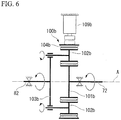
- a second modified example of a transmission mechanism and a state change mechanism will be described with reference to FIG. 6 .
- a transmission mechanism 100b according to the embodiment is also a planetary gear mechanism including a sun gear 101b, a plurality of planetary gears 102b, a carrier 103b, and an internal gear 104b like the transmission mechanism 100 according to the first embodiment.
- the sun gear 101b is fixed to a motor rotational shaft 72 and rotates about an axis A.
- the plurality of planetary gears 102b are arranged in an outer circumference of the sun gear 101b and mesh with the sun gear 101b.
- the plurality of planetary gears 102b rotate about central axes of the plurality of planetary gears 102b themselves and revolve about the axis A.
- the internal gear 104b meshes with the plurality of planetary gears 102b.
- the internal gear 104b can rotate about the axis A.
- the carrier 103b rotatably supports each planetary gear 102b.
- the carrier 103b is fixed to a compressor rotating shaft 82 and rotates about the axis A
- the sun gear 101b constitutes a motor-side transmission member and the carrier 103b constitutes a compressor-side transmission member. Furthermore, the internal gear 104b and the plurality of planetary gears 102b constitute an intermediate transmission member. The internal gear 104b also constitutes a state change transmission member among a plurality of intermediate transmission members.
- a state change mechanism 109b according to the embodiment is also arranged in a housing 61 and directly or indirectly attached to the housing 61.
- the state change mechanism 109b functions as a brake configured to suppress the rotation of the internal gear (the state change transmission member) 104b.
- the sun gear 101b of the transmission mechanism 100b rotates along with the rotation of the motor rotational shaft 72
- the plurality of planetary gears 102b revolve while rotating.
- the internal gear 104b rotates due to the rotation and the revolution of the plurality of planetary gears 102b.
- the carrier 103b rotates due to the revolution of the plurality of planetary gears 102b while the internal gear 104b is rotating.
- the rotation of the internal gear 104b is suppressed using the state change mechanism 109b
- the sun gear 101b of the transmission mechanism 100b rotates along with the rotation of the motor rotational shaft 72
- the plurality of planetary gears 102b revolve while rotating in a state in which the internal gear 104b does not rotate.
- the carrier 103b rotates due to the revolution of the plurality of planetary gears 102b in the state in which the internal gear 104b does not rotate.
- the number of rotations of the compressor rotating shaft 82 that is, the amount of discharging of a gas from the hermetic electric compressor 60, can be changed by operating the state change mechanism 109b.
- the sun gear 101b is fixed to the motor rotational shaft 72 and constitutes the motor-side transmission member
- the carrier 103b is fixed to the compressor rotating shaft 82 and constitutes the compressor-side transmission member
- the carrier 103b may be fixed to the motor rotational shaft 72 and constitute the motor-side transmission member
- the sun gear 101b may be fixed to the compressor rotating shaft 82 and constitute the compressor-side transmission member.
- a third modified example of a transmission mechanism and a state change mechanism will be described with reference to FIG. 7 .
- a transmission mechanism 110 is a con-ball type continuously variable transmission mechanism including an input disk 111, an output disk 113, and a plurality of balls 115.
- the input disk 111 is fixed to a motor rotational shaft 72 and rotates about an axis A.
- the output disk 113 is fixed to a compressor rotating shaft 82 and rotates about the axis A.
- Annular contact surfaces 112 and 114 are formed about the axis A on the input disk 111 and the output disk 113.
- the input disk 111 and the output disk 113 face each other while being separated from each other.
- Outer surfaces of the balls 115 form contact surfaces 116.
- each of the contact surfaces 116 is a spherical surface.
- the balls 115 rotate about intersection axes Ac which can pass through centers Cb of the balls 115 and intersect the axis A.
- Each of the contact surfaces 116 of the balls 115 comes into contact with each of the contact surfaces 112 of the input disk 111 and each of the contact surfaces 114 of the output disk 113.
- a line formed by the intersection of the annular contact surface 112 of the input disk 111 and a virtual plane including the axis A is formed by a part of a circle with the center Cb of the ball 115 as a center.
- a line formed by the intersection of the annular contact surface 114 of the output disk 113 and the above virtual plane are also formed by a part of a circle with the center Cb of the ball 115 as a center.
- both of the contact surface 112 of the input disk 111 and the contact surface 114 of the output disk 113 form concave surfaces which are smoothly concave in directions away from the centers Cb of the balls 115.
- the input disk 111 constitutes a motor-side transmission member
- the output disk 113 constitutes a compressor-side transmission member
- the balls 115 constitute an intermediate transmission member and constitute the state change transmission member.
- Each of the balls 115 is a spherical surface transmission member.
- a state change mechanism 119 changes the inclination of each of the intersection axes Ac of the ball 115 with respect to the center Cb of the ball 115.
- a radius of rotation of the ball 115 in a portion in the contact surface 116 of the ball 115 in contact with the contact surface 112 of the input disk 111 changes.
- the number of rotations of the ball 115 changes with respect to the number of rotations of the input disk 111.
- the number of rotations of the compressor rotating shaft 82 can be changed by changing the inclination of the intersection axis Ac of the ball 115. Note that, in the embodiment, unlike the above embodiment and modified examples, the number of rotations of the compressor rotating shaft 82 can be continuously changed in a range in which the intersection axis Ac can be inclined.
- a fourth modified example of a transmission mechanism and a state change mechanism will be described with reference to FIG. 8 .
- a transmission mechanism 110a is a toroidal type continuously variable transmission mechanism including an input disk 111a, an output disk 113a, and a plurality of rollers 115a.
- the input disk 111a is fixed to a motor rotational shaft 72 and rotates about an axis A.
- the output disk 113a is fixed to a compressor rotating shaft 82 and rotates about the axis A.
- Annular contact surfaces 112a and 114a are formed about the axis A on the input disk 111a and the output disk 113a.
- the input disk 111a and the output disk 113a face each other while away from each other.
- Each of the rollers 115a rotates about an intersection axis Ac intersecting the axis A.
- Annular contact surfaces 116a are formed on the roller 115a with each of the intersection axes Ac as a center.
- Each of the contact surfaces 116a is formed by a part of a spherical surface having a point on the intersection axis Ac as a center Cr.
- Each of the contact surfaces 116a of the roller 115a comes into contact with each of the contact surfaces 112a of the input disk 111a and each of the contact surfaces 114a of the output disk 113a.
- a line formed by the intersection of the annular contact surface 112a of the input disk 111a and a virtual plane including the axis A is formed by a part of a circle with the center Cr of a spherical surface as a center.
- a line formed by the intersection of the annular contact surface 114a of the output disk 113a and the above virtual plane is also formed by a part of a circle with the center Cr of a spherical surface as a center.
- both of the contact surface 112a of the input disk 111a and the contact surface 114a of the output disk 113a form concave surfaces which are smoothly concave in directions away from the centers Cr of the spherical surfaces.
- the input disk 111a constitutes a motor-side transmission member
- the output disk 113a constitutes a compressor-side transmission member
- the roller 115a constitutes an intermediate transmission member and constitutes the state change transmission member.
- the roller 115a is a spherical surface transmission member.
- a state change mechanism 119a changes the inclination of the intersection axis Ac of the roller 115a with respect to the center Cr of the spherical surface.
- a radius of rotation of the input disk 111a in a portion in the contact surface 112a of the input disk 111a in contact with the contact surface 116a of the roller 115a changes.
- the number of rotations of the roller 115a changes with respect to the number of rotations of the input disk 111a.
- the number of rotations of the compressor rotating shaft 82 can be changed by changing the inclination of the intersection axis Ac of the roller 115a. Note that, also in the embodiment, like in the third modified example, the number of rotations of the compressor rotating shaft 82 can be continuously changed in a range in which the intersection axis Ac can be inclined.
- a fifth modified example of a transmission mechanism and a state change mechanism will be described with reference to FIG. 9 .
- a transmission mechanism 120 includes an input bevel gear 121, an output bevel gear 122, a first intermediate bevel gear 123a, a second intermediate bevel gear 123b, and an intermediate rotary shaft 124.
- the input bevel gear 121 is fixed to the motor rotational shaft 72 and rotates about the axis A.
- the output bevel gear 122 is fixed to the compressor rotating shaft 82 and rotates about the axis A.
- the input bevel gear 121 and the output bevel gear 122 face each other while away from each other.
- the intermediate rotary shaft 124 is arranged to be rotatable about an orthogonal axis Ao which is orthogonal to the axis A in the middle between the input bevel gear 121 and the output bevel gear 122.
- the intermediate rotary shaft 124 extends in a direction in which the orthogonal axis Ao extends.
- the first intermediate bevel gear 123a is fixed to the intermediate rotary shaft 124 to mesh with the input bevel gear 121 and the output bevel gear 122.
- the second intermediate bevel gear 123b is fixed to the intermediate rotary shaft 124 to mesh with the input bevel gear 121 and the output bevel gear 122 on an opposite side of the first intermediate bevel gear 123a with respect to the axis A.
- the second intermediate bevel gear 123b does not mesh with the input bevel gear 121 and the output bevel gear 122 when the first intermediate bevel gear 123a meshes with the input bevel gear 121 and the output bevel gear 122.
- first intermediate bevel gear 123a does not mesh with the input bevel gear 121 and the output bevel gear 122 when the second intermediate bevel gear 123b meshes with the input bevel gear 121 and the output bevel gear 122.
- a pitch circle diameter of the second intermediate bevel gear 123b is smaller than a pitch circle diameter of the first intermediate bevel gear 123a.
- the number of teeth of the second intermediate bevel gear 123b is smaller than the number of teeth of the first intermediate bevel gear 123a.
- the input bevel gear 121 constitutes a motor-side transmission member
- the output bevel gear 122 constitutes a compressor-side transmission member
- the plurality of intermediate bevel gears 123a and 123b and the intermediate rotary shaft 124 constitute an intermediate transmission member and constitute a state change transmission member.
- a state change mechanism 129 moves the intermediate rotary shaft 124 in a direction in which the orthogonal axis Ao extends and switches between a first transmission state in which only the first intermediate bevel gear 123a meshes with the input bevel gear 121 and the output bevel gear 122 and a second transmission state in which only the second intermediate bevel gear 123b meshes with the input bevel gear 121 and the output bevel gear 122.
- the number of teeth of the first intermediate bevel gear 123a is different from the number of teeth of the second intermediate bevel gear 123b. For this reason, the number of rotations of the compressor rotating shaft 82 at a time of the first transmission state is different from the number of rotations of the compressor rotating shaft 82 at a time of the second transmission state. Thus, also in the embodiment, the number of rotations of the compressor rotating shaft 82 can be changed.
- first intermediate bevel gear 123a and the second intermediate bevel gear 123b are joined using the intermediate rotary shaft 124 in the embodiment, the first intermediate bevel gear 123a and the second intermediate bevel gear 123b may not be joined. In this case, a mechanism of moving only the first intermediate bevel gear 123a in the direction in which the orthogonal axis Ao extends and a mechanism of moving only the second intermediate bevel gear 123b in the direction in which the orthogonal axis Ao extends are provided.
- the two intermediate bevel gears 123a and 123b having different numbers of teeth from each other are provided in the embodiment, three or more intermediate bevel gears having different numbers of teeth from each other may be provided.
- the state change mechanism 129 selectively meshes only one intermediate bevel gear among the three or more intermediate bevel gears with the input bevel gear 121 and the output bevel gear 122.
- the compression mechanism is an example of the rotary compression mechanism.
- the compression mechanism may be a scroll compression mechanism.
- the scroll compression mechanism includes a compressor rotating shaft, a turning scroll having a spiral turning tooth about a position which is eccentric with respect to the compressor rotating shaft, and a fixed scroll having a spiral fixed tooth about the motor rotational shaft 72.
- a spiral space formed by a fixed scroll (a compression chamber formation member) forms a compression chamber.
- a turning scroll is arranged in a compression chamber serving as a spiral space.
- the turning scroll is fixed to the compressor rotating shaft 82.
- Such a turning scroll is arranged in a compression chamber serving as a spiral space.
- the turning scroll (a compressor rotor) revolves in the compression chamber as a center of the compressor rotating shaft 82 due to the rotation of the compressor rotating shaft 82.
- the turning scroll (the compressor rotor) is eccentric due to the rotation of the compressor rotating shaft 82.
- the turning scroll is eccentric in the compression chamber, thereby compressing an inflow refrigerant.
Landscapes
- Engineering & Computer Science (AREA)
- Mechanical Engineering (AREA)
- General Engineering & Computer Science (AREA)
- Applications Or Details Of Rotary Compressors (AREA)
- Friction Gearing (AREA)
- Structure Of Transmissions (AREA)
- Compressor (AREA)
Abstract
Description
- The present invention relates to a hermetic electric compressor including an electric motor, a compression mechanism operating using the rotation of the electric motor, and a housing configured to collectively cover the electric motor and the compression mechanism and a refrigeration cycle including the same.
- Examples of a hermetic electric compressor include a rotary compressor disclosed in the following Patent Document 1.
- Such a compressor includes an electric motor, a compression mechanism operating using the rotation of the electric motor, and a housing configured to collectively cover the electric motor and the compression mechanism. The compression mechanism includes a compressor rotating shaft directly connected to a motor rotational shaft of the electric motor, a rotor fixed eccentrically to the compressor rotating shaft, and a cylinder configured to form a cylindrical compression chamber with the compressor rotating shaft as a center. The rotor eccentrically rotates in the compression chamber, thereby compressing a gas flowing in the compression chamber.
- [Patent Document 1] Japanese Unexamined Patent Application, First Publication No.
2015-183613 - A hermetic compressor is used as one constituent element of a refrigeration cycle of an air conditioner or the like in many cases, and it is indispensable to change the cooling or heating ability in accordance with an indoor environment to operate the air conditioner. For this reason, ability to change the rotational frequency of a compressor rotating shaft is required in a hermetic compressor used as one constituent element of a refrigeration cycle.
- Examples of a method of changing the number of rotations of a compressor rotating shaft include a method of supplying alternating current (AC) power to an electric motor via an inverter and changing a frequency of the AC power supplied to the electric motor using the inverter. However, in such a method of driving a compressor, the inverter is required separately from the compressor and thus the total manufacturing costs are high.
- Therefore, an objective of the present invention is to provide a hermetic compressor for which the manufacturing costs are able to be minimized and the rotational frequency of a compressor rotating shaft is able to be changed, and a refrigeration cycle including the same.
- A hermetic electric compressor according to a first aspect of the present invention for the purpose of achieving the above objective includes: an electric motor; a compression mechanism operating using the rotation of the electric motor; a transmission mechanism including a plurality of transmission members and configured to transmit rotational torque of the electric motor to the compression mechanism; a state change mechanism configured to change a state of at least one of the plurality of transmission members with respect to another transmission member; and a housing configured to collectively cover the electric motor, the compression mechanism, the transmission mechanism, and the state change mechanism. The electric motor includes a motor rotational shaft, a motor rotor fixed to the motor rotational shaft, and a motor stator fixed to an inner surface of the housing to face the motor rotor. The compression mechanism includes a compressor rotating shaft, a compressor rotor fixed to the compressor rotating shaft, and a compression chamber formation member configured to form a compression chamber in which the compressor rotor is accommodated. The transmission mechanism includes a motor-side transmission member fixed to the motor rotational shaft, a compressor-side transmission member fixed to the compressor rotating shaft, and one or more intermediate transmission members configured to transmit the rotation of the motor-side transmission member to the compressor-side transmission member as the transmission members. The state change mechanism changes a state of a state change transmission member serving as at least one of the one or more intermediate transmission members with respect to the motor-side transmission member or the compressor-side transmission member and changes the rotational speed of the compressor rotating shaft rotating along with the motor rotational shaft.
- In the hermetic electric compressor, the number of rotations of the compressor rotating shaft can be changed by operating the state change mechanism. Furthermore, in the hermetic electric compressor, since the number of rotations of the compressor rotating shaft can be changed without using an inverter, the manufacturing costs can be minimized.
- In a hermetic electric compressor according to a second aspect of the present invention for the purpose of achieving the above objective,
in the hermetic electric compressor according to the first aspect, the motor rotational shaft and the compressor rotating shaft may be located on the same axis. - In the hermetic electric compressor, since the motor rotational shaft and the compressor rotating shaft are located on the same axis, an increase in size in the radial direction can be minimized.
- In a hermetic electric compressor according to a third aspect of the present invention for the purpose of achieving the above objective,
in the hermetic electric compressor according to the first or second aspect, the compression mechanism may be a rotary compression mechanism, the compressor rotor of the rotary compression mechanism may be eccentric with respect to a central axis of the compressor rotating shaft and fixed to the compressor rotating shaft, and the compression chamber formation member of the rotary compression mechanism may be a cylinder configured to form a cylindrical compression chamber with the central axis of the compressor rotating shaft as a center and cover an outer circumference of the compressor rotor. - In a hermetic electric compressor according to a fourth aspect of the present invention for the purpose of achieving the above objective,
in the hermetic electric compressor according to any one of the first to third aspects, the transmission mechanism may be a planetary gear mechanism including a sun gear rotatable about an axis, a plurality of planetary gears arranged on the outer circumference of the sun gear and meshing with the sun gear, a carrier configured to maintain respective intervals between the plurality of planetary gears, and an internal gear arranged on an outer circumference of the plurality of planetary gears and meshing with the plurality of planetary gears. A first transmission member selected from the group consisting of the motor-side transmission member, the compressor-side transmission member, and the state change transmission member may be constituted as a first one selected from the group consisting of the sun gear, the carrier, and the internal gear. A second transmission member selected from the group consisting of the motor-side transmission member, the compressor-side transmission member, and the state change transmission member may be constituted of a second one selected from the group consisting of the sun gear, the carrier, and the internal gear. A third transmission member selected from the group consisting of the motor-side transmission member, the compressor-side transmission member, and the state change transmission member may be constituted of a third one selected from the group consisting of the sun gear, the carrier, and the internal gear. The state change mechanism restricts rotation of the state change transmission member. - In a hermetic electric compressor according to a fifth aspect of the present invention for the purpose of achieving the above objective,
in the hermetic electric compressor according to any one of the first to third aspects, the transmission mechanism may include an input disk and an output disk rotating about the same axis, forming annular contact surfaces with the axis as a center, and facing each other to be away from each other, and a spherical surface transmission member rotating about an intersection axis which is able to intersect the axis and having a contact surface formed to be in contact with the contact surface of the input disk and the contact surface of the output disk. The contact surfaces of the spherical surface transmission member may be formed by at least a part of a spherical surface with one point on the intersection axis as a center. Both of the annular contact surface of the input disk and the annular contact surface of the output disk may be concave surfaces which are smoothly concave in directions away from a center of the spherical surface. The input disk may constitute the motor-side transmission member. The output disk may constitute the compressor-side transmission member. The spherical surface transmission member may constitute the state change transmission member. The state change mechanism may change an inclination of the intersection axis of the spherical surface transmission member with respect to the center of the spherical surface. - In a hermetic electric compressor according to a sixth aspect of the present invention for the purpose of achieving the above objective,
in the hermetic electric compressor according to any one of the first to third aspects, the transmission mechanism may include an input bevel gear and an output bevel gear rotating about the same axis and facing each other to be away from each other and a plurality of intermediate bevel gears rotatable about an orthogonal axis which is orthogonal to the axis and capable of meshing with the input bevel gear and the output bevel gear. The input bevel gear may constitute the motor-side transmission member. The output bevel gear may constitute the compressor-side transmission member. The plurality of intermediate bevel gears may constitute the state change transmission member. The plurality of intermediate bevel gears may have different numbers of teeth from each other. The state change mechanism may selectively mesh only one of the plurality of intermediate bevel gears with the input bevel gear and the output bevel gear. - A refrigeration cycle according to a seventh aspect of the present invention for the purpose of achieving the above objective includes:
- a circulation line through which a refrigerant flows; the hermetic electric compressor according to any one of claims 1 to 6 arranged in the circulation line and configured to compress the refrigerant in a state of gas; a first heat exchanger arranged in the circulation line and configured to exchange heat between the refrigerant flowing through the circulation line and a first medium to change a phase of the refrigerant; a second heat exchanger arranged in the circulation line and configured to exchange heat between the refrigerant flowing through the circulation line and a second medium to change a phase of the refrigerant; and an expansion valve arranged in a part of a circulation line which is a circulation line between the first heat exchanger and the second heat exchanger, in which the hermetic electric compressor is not arranged between the first heat exchanger and the second heat exchanger.
- According to an aspect of the present invention, it is possible to reduce manufacturing costs and change the number of rotations of a compressor rotating shaft.
-
-
FIG. 1 is a cross-sectional view of a hermetic electric compressor according to an embodiment of the present invention. -
FIG. 2 is a cross-sectional view taken along line II-II inFIG. 1 . -
FIG. 3 is a diagram showing a constitution of a transmission mechanism according to the embodiment of the present invention. -
FIG. 4 is a system diagram of a refrigeration cycle according to the embodiment of the present invention. -
FIG. 5 is a diagram showing a constitution of a transmission mechanism in a first modified example according to the embodiment of the present invention. -
FIG. 6 is a diagram showing a constitution of a transmission mechanism in a second modified example according to the embodiment of the present invention. -
FIG. 7 is a diagram showing a constitution of a transmission mechanism in a third modified example according to the embodiment of the present invention. -
FIG. 8 is a diagram showing a constitution of a transmission mechanism in a fourth modified example according to the embodiment of the present invention. -
FIG. 9 is a diagram showing a constitution of a transmission mechanism in a fifth modified example according to the embodiment of the present invention. - Hereinafter, various embodiments of a vessel according to the present invention will be described using the drawings.
- A first embodiment of a hermetic electric compressor according to the present invention will be described with reference to
FIGS. 1 to 4 . - As shown in
FIG. 1 , a hermeticelectric compressor 60 according to the embodiment includes anelectric motor 71, acompression mechanism 81 operating due to the rotation of theelectric motor 71, atransmission mechanism 100 configured to transmit the rotational torque of theelectric motor 71 to thecompression mechanism 81, and ahousing 61 configured to collectively cover these. - The
housing 61 includes abody part 62, afirst lid 63, and asecond lid 64. Thebody part 62 has a cylindrical shape with an axis A as a center, and a first side Da1 in an axial direction Da along which the axis A extends and a second side Da2 on an opposite side thereto are open. Thefirst lid 63 closes the opening on the first side Da1 in thebody part 62. Thesecond lid 64 closes the opening on the second side Da2 in thebody part 62. Asuction port 65 configured to suction a gas is formed in a portion of thebody part 62 on the first side Da1. Furthermore, adischarge port 66 configured to discharge a gas is formed in thesecond lid 64. - The
electric motor 71 includes a motorrotational shaft 72, amotor rotor 73, and amotor stator 74. The motorrotational shaft 72 extends in the axial direction Da about the axis A. The motorrotational shaft 72 rotates about the axis A. Themotor rotor 73 is fixed to an outer circumference of the motorrotational shaft 72. Themotor stator 74 is fixed to an inner circumferential surface of thebody part 62 and faces themotor rotor 73 in a radial direction with respect to the axis A. A slight gap is present between an outer circumferential surface of themotor rotor 73 and an inner circumferential surface of themotor stator 74. Arefrigerant flow path 75 extending in the axial direction Da is formed between themotor stator 74 and the inner circumferential surface of thebody part 62. - The
compression mechanism 81 is a rotary compression mechanism. As shown inFIGS. 1 and2 , thecompression mechanism 81 includes acompressor rotating shaft 82, acompressor rotor 83, and a cylinder (a compression chamber formation member) 84. Thecompressor rotating shaft 82 extends in the axial direction Da about the axis A. Thecompressor rotating shaft 82 rotates about the axis A. Thecompressor rotor 83 is fixed to thecompressor rotating shaft 82. Thecompressor rotor 83 has a cylindrical shape. A central axis of thecylindrical compressor rotor 83 is eccentric with respect to a part which is parallel to the axis A with respect to the axis A. Thecylinder 84 includes a cylindrical cylindermain body 85 with the axis A as a center, afirst cylinder lid 86, and asecond cylinder lid 87. The cylindermain body 85 has a cylindrical shape with the axis A as a center, and the first side Da1 and the second side Da2 thereof are open. Thefirst cylinder lid 86 closes the opening on the first side Da1 in the cylindermain body 85. Thesecond cylinder lid 87 closes the opening on the second side Da2 in the cylindermain body 85. A space surrounded by the cylindermain body 85, thefirst cylinder lid 86, and thesecond cylinder lid 87 forms a cylinder chamber (a compression chamber) S in which thecompressor rotor 83 is accommodated. The compression chamber S has a cylindrical shape with the axis A as a center. The cylindermain body 85 is fixed to the inner circumferential surface of thebody part 62 of thehousing 61. Thefirst cylinder lid 86 and thesecond cylinder lid 87 are fixed to the cylindermain body 85 with bolts. Both of thefirst cylinder lid 86 and thesecond cylinder lid 87 rotatably support thecompressor rotating shaft 82 about the axis A. Thus, thefirst cylinder lid 86 and thesecond cylinder lid 87 function as a bearing. The cylindermain body 85 has asuction port 88i passing from an outer circumferential surface thereof into the compression chamber S and ablade groove 89 which is concave radially outward from an inner circumferential surface thereof with respect to the axis A formed therein. Thesuction port 88i communicates with thesuction port 65 of thehousing 61. A discharge port 88o passing in the axial direction Da is formed in thesecond cylinder lid 87. Thecompressor rotor 83 revolves about the axis A along with the rotation of thecompressor rotating shaft 82 while in contact with an inner circumferential surface of the cylindermain body 85. In other words, thecompressor rotor 83 rotates eccentrically with respect to the axis A while in contact with the inner circumferential surface of the cylindermain body 85. - The
compression mechanism 81 includes ablade 91, ablade spring 92, adischarge valve 93, and adischarge cover 94. Theblade 91 is accommodated in theblade groove 89 so that a part of theblade 91 can protrude into the compression chamber S from theblade groove 89. Theblade spring 92 is accommodated in theblade groove 89 and pushes theblade 91 in a direction in which theblade 91 protrudes into the compression chamber S. A distal end of theblade 91 is in contact with an outer circumferential surface of thecompressor rotor 83 at all times when theblade 91 is pushed by theblade spring 92. A crescent-shaped space is formed between the inner circumferential surface of the cylindermain body 85 and the outer circumferential surface of thecompressor rotor 83 which is eccentric in the compression chamber S in the compression chamber S. Such a crescent-shaped space is divided into two spaces using theblade 91 protruding from the cylindermain body 85 into the compression chamber S. One space of the two spaces forms a suction volume Ss and the other space forms a compression volume Sc. Thesuction port 88i formed in the cylindermain body 85 is joined to this suction volume Ss. Furthermore, the discharge port 88o formed in thesecond cylinder lid 87 is joined to such a compression volume Sc. Thedischarge valve 93 is provided at a position, at which the discharge port 88o opens, in a surface of thesecond cylinder lid 87 on the second side Da2. The discharge cover 94 covers a portion of thesecond cylinder lid 87 on the second side Da2. Adischarge port 95 configured to discharge a refrigerant, which flows from an inside of the compression chamber S into thedischarge cover 94 through thedischarge valve 93, from thedischarge cover 94 is formed in thedischarge cover 94. - As shown in
FIG. 3 , thetransmission mechanism 100 is a planetary gear mechanism. Thetransmission mechanism 100 includes asun gear 101, a plurality ofplanetary gears 102, acarrier 103, and aninternal gear 104. Thesun gear 101 is fixed to the motorrotational shaft 72 and rotates about the axis A. The plurality ofplanetary gears 102 are arranged in an outer circumference of thesun gear 101 and mesh with thesun gear 101. The plurality ofplanetary gears 102 rotate about central axes of the plurality ofplanetary gears 102 themselves and revolve about the axis A. In theinternal gear 104, a plurality of teeth directed inward in the radial direction with respect to the axis A are annularly arranged about the axis A. In theinternal gear 104, thecompressor rotating shaft 82 is fixed and rotates about the axis A. Theinternal gear 104 meshes with the plurality ofplanetary gears 102. Thecarrier 103 maintains respective intervals between the plurality ofplanetary gears 102 in a circumferential direction with respect to the axis A. Thecarrier 103 supports eachplanetary gear 102 so that eachplanetary gear 102 can rotate on its own axis. Thecarrier 103 is supported by the motorrotational shaft 72 to be rotatable about the axis A. - In the
transmission mechanism 100, thesun gear 101 forms a motor-side transmission member and theinternal gear 104 forms a compressor-side transmission member. Furthermore, the plurality ofplanetary gears 102 and thecarrier 103 constitute an intermediate transmission member. Thecarrier 103 also constitutes a state change transmission member among a plurality of intermediate transmission members. - The hermetic
electric compressor 60 according to the embodiment further includes astate change mechanism 109. Thestate change mechanism 109 is arranged in thehousing 61 and attached directly or indirectly to thehousing 61. Thestate change mechanism 109 changes the state of one transmission member with respect to another transmission member among a plurality of transmission members constituting thetransmission mechanism 100. To be specific, thestate change mechanism 109 suppresses the rotation of the carrier (the state change transmission member) 103 which is rotated along with the rotation of thesun gear 101. Thus, thestate change mechanism 109 functions as a brake configured to suppress the rotation of thecarrier 103. Note that, when the rotation of thecarrier 103 is suppressed, the revolution of the plurality ofplanetary gears 102 is suppressed. - As shown in
FIG. 4 , the hermeticelectric compressor 60 according to the embodiment described above constitutes a part of a refrigeration cycle. Such a refrigeration cycle includes acirculation line 10, an accumulator 5, a first heat exchanger 1, asecond heat exchanger 2, an expansion valve 3, a four-way switching valve 4, the accumulator 5, and thecirculation line 10 in addition to the hermeticelectric compressor 60. - A refrigerant R flows through the
circulation line 10. All of the hermeticelectric compressor 60, the first heat exchanger 1, thesecond heat exchanger 2, the expansion valve 3, and the four-way switching valve 4 are provided in thecirculation line 10. The first heat exchanger 1 changes a phase of the refrigerant R by exchanging heat between the refrigerant R and a first medium M1. Thesecond heat exchanger 2 changes a phase of the refrigerant R by exchanging heat between the refrigerant R and a second medium M2. The first heat exchanger 1 includes a firstrefrigerant port 1a and a secondrefrigerant port 1b. Furthermore, thesecond heat exchanger 2 also includes a firstrefrigerant port 2a and a secondrefrigerant port 2b. The accumulator 5 has a function of temporarily storing the refrigerant R and separating a liquid-phase refrigerant R from a vapor-phase refrigerant R. Arefrigerant inlet 5a and arefrigerant outlet 5b are formed in the accumulator 5. The hermeticelectric compressor 60 compresses a gas refrigerant R from the accumulator 5. The expansion valve 3 reduces a pressure of a liquid refrigerant R. The four-way switching valve 4 has four ports and can selectively change a flow of a refrigerant R between ports. The four-way switching valve 4 changes a flow of a refrigerant R between ports by selectively selecting a first connection mode and a second connection mode. The first connection mode is a mode in which afirst port 4a and asecond port 4b are connected and athird port 4c and afourth port 4d are connected. Furthermore, the second connection mode is a mode in which thesecond port 4b and thethird port 4c are connected and thefourth port 4d and thefirst port 4a are connected. - The
circulation line 10 includes afirst line 11 connected to the firstrefrigerant port 1a of the first heat exchanger 1, asecond line 12 connected to the firstrefrigerant port 2a of thesecond heat exchanger 2, athird line 13 connected to the secondrefrigerant port 2b of thesecond heat exchanger 2, afourth line 14 connected to therefrigerant inlet 5a of the accumulator 5, and afifth line 15 connected to thedischarge port 66 of the hermeticelectric compressor 60. One end of two ends of thefirst line 11 is connected to thesecond port 4b of the four-way switching valve 4 and the other end thereof is connected to the firstrefrigerant port 1a of the first heat exchanger 1 as described above. One end of two ends of thesecond line 12 is connected to the secondrefrigerant port 1b of the first heat exchanger 1 and the other end thereof is connected to the firstrefrigerant port 2a of thesecond heat exchanger 2 as described above. The expansion valve 3 is provided in thesecond line 12. One end of two ends of thethird line 13 is connected to the secondrefrigerant port 2b of thesecond heat exchanger 2 as described above and the other end thereof is connected to thefourth port 4d of the four-way switching valve 4. One end of two ends of thefourth line 14 is connected to thethird port 4c of the four-way switching valve 4 and the other end thereof is connected to therefrigerant inlet 5a of an actuator as described above. One end of two ends of thefifth line 15 is connected to thedischarge port 66 of the hermeticelectric compressor 60 as described above and the other end thereof is connected to thefirst port 4a of the four-way switching valve 4. Furthermore, therefrigerant outlet 5b of the accumulator 5 is connected to thesuction port 65 of the hermeticelectric compressor 60. - An operation of the refrigeration cycle described above will be described below.
- First, a basic operation of a refrigeration cycle when the four-way switching valve 4 is in the first connection mode will be described. Note that the first connection mode is a mode in which the
first port 4a and thesecond port 4b are connected and thethird port 4c and thefourth port 4d are connected as described above. - A gas refrigerant R compressed by the herms into the first heat exchanger 1 via the
fifth line 15, the of the four-way switching valve 4, and thefirst line 11. The gas refrigerant R exchanges heat with the first medium M1 using the first heat exchanger 1. As a result, the first medium M1 is heated. On the other hand, the gas refrigerant R is cooled and condensed to be converted into a liquid refrigerant R. Thus, the first heat exchanger 1 functions as a condenser when the four-way switching valve 4 is in the first connection mode. - The refrigerant R liquefied using the first heat exchanger 1 flows into the
second heat exchanger 2 via thesecond line 12. In a process in which the refrigerant R flows through thesecond line 12, the refrigerant R is decompressed using the expansion valve 3 arranged in thesecond line 12. - The liquid refrigerant R exchanges heat with the second medium M2 using the
second heat exchanger 2. As a result, the second medium M2 is cooled. On the other hand, the liquid refrigerant R is heated and vaporized to be converted into a gas refrigerant R. Thus, thesecond heat exchanger 2 functions as an evaporator when the four-way switching valve 4 is in the first connection mode. - The refrigerant R vaporized using the
second heat exchanger 2 flows into the accumulator 5 via thethird line 13, thefourth port 4d and thethird port 4c of the four-way switching valve 4, and thefourth line 14. In the gas refrigerant R, a slight amount of mist-like liquid refrigerant R may remain in some cases. The accumulator 5 separates a liquid refrigerant R from a gas refrigerant R and discharges the gas refrigerant R. - The gas refrigerant R from the accumulator 5 flows into the hermetic
electric compressor 60. The gas refrigerant R is compressed by the hermeticelectric compressor 60 and discharged through thedischarge port 66 of the hermeticelectric compressor 60. The gas refrigerant R discharged from the hermeticelectric compressor 60 flows into the first heat exchanger 1 via thefifth line 15, thefirst port 4a and thesecond port 4b of the four-way switching valve 4, and thefirst line 11. - As described above, the refrigeration cycle according to the embodiment transfers the heat of the second medium M2 to the first medium M1 via the refrigerant R in the first connection mode.
- Next, a basic operation of a refrigeration cycle when the four-way switching valve 4 is in the second connection mode will be described. Note that the second connection mode is a mode in which the
second port 4b and thethird port 4c are connected and thefourth port 4d and thefirst port 4a are connected as described above. - The gas refrigerant R compressed by the hermetic
electric compressor 60 flows into thesecond heat exchanger 2 via thefifth line 15, thefirst port 4a and thefourth port 4d of the four-way switching valve 4, and thethird line 13. The gas refrigerant R exchanges heat with the second medium M2 using thesecond heat exchanger 2. As a result, the second medium M2 is heated. On the other hand, the gas refrigerant R is cooled and condensed to be converted into a liquid refrigerant R. Thus, thesecond heat exchanger 2 functions as a condenser when the four-way switching valve 4 is in the second connection mode. - The refrigerant R liquefied using the
second heat exchanger 2 flows into the first heat exchanger 1 via thesecond line 12. In a process in which the refrigerant R flows through thesecond line 12, the refrigerant R is decompressed using the expansion valve 3 arranged in thesecond line 12. - The liquid refrigerant R exchanges heat with the first medium M1 using the first heat exchanger 1. As a result, the first medium M1 is cooled. On the other hand, the liquid refrigerant R is heated and vaporized to be converted into a gas refrigerant R. Thus, the first heat exchanger 1 functions as an evaporator when the four-way switching valve 4 is in the second connection mode.
- The refrigerant R vaporized using the first heat exchanger 1 flows into the accumulator 5 via the
first line 11, thesecond port 4b and thethird port 4c of the four-way switching valve 4, and thefourth line 14. The gas refrigerant R from the accumulator 5 flows into the hermeticelectric compressor 60. The gas refrigerant R is compressed by the hermeticelectric compressor 60 and discharged through thedischarge port 66 of the hermeticelectric compressor 60. - As described above, the refrigeration cycle according to the embodiment transfers the heat of the first medium M1 to the second medium M2 via the refrigerant R when the four-way switching valve 4 is in the second connection mode.
- The refrigeration cycle described above includes the four-way switching valve 4. As described above, the four-way switching valve 4 is provided for switching between a case in which the first heat exchanger 1 is caused to function as a condenser and a case in which the first heat exchanger 1 is caused to function as an evaporator. For this reason, in a case in which the first heat exchanger 1 is exclusively caused to function as a condenser and a case in which the first heat exchanger 1 is exclusively caused to functions an evaporator, the four-way switching valve 4 is not required.
- A gas flowing into the
housing 61 through thesuction port 65 of the hermeticelectric compressor 60 flows into the compression chamber S through thesuction port 88i of thecylinder 84. Thecompressor rotating shaft 82 rotates about the axis A along with the rotation of the motorrotational shaft 72. Here, the rotation of the motorrotational shaft 72 is decelerated using thetransmission mechanism 100 and transmitted to the motorrotational shaft 72. When thecompressor rotating shaft 82 rotates, thecompressor rotor 83 is eccentric in the compression chamber S along with this rotation. The refrigerant flowing into the compression chamber S is compressed due to the eccentric rotation in the compression chamber S of thecompressor rotor 83. The refrigerant compressed in the compression chamber S flows into thedischarge cover 94 via the discharge port 88o of thecylinder 84 and thedischarge valve 93. The refrigerant flowing into thedischarge cover 94 flows outside of thedischarge cover 94 through thedischarge port 95. The refrigerant is discharged through thedischarge port 66 of thehousing 61 via therefrigerant flow path 75 between themotor stator 74 and thebody part 62 of thehousing 61. - In the embodiment, the number of rotations of the
compressor rotating shaft 82 can be changed by operating thestate change mechanism 109. In a case in which the rotation of the carrier (the state change transmission member) 103 is not suppressed using thestate change mechanism 109, when thesun gear 101 of thetransmission mechanism 100 rotates along with the rotation of the motorrotational shaft 72, the plurality ofplanetary gears 102 revolve while rotating. Theinternal gear 104 rotates due to the rotation and the revolution of the plurality ofplanetary gears 102. - On the other hand, in a case in which the rotation of the
carrier 103 is suppressed using thestate change mechanism 109, when thesun gear 101 of thetransmission mechanism 100 rotates along with the rotation of the motorrotational shaft 72, the plurality ofplanetary gears 102 rotate but do not revolve. Theinternal gear 104 rotates only due to the rotation of the plurality ofplanetary gears 102. Thus, in the embodiment, the number of rotations of thecompressor rotating shaft 82, that is, an amount of discharging of the refrigerant from the hermeticelectric compressor 60, can be changed by operating thestate change mechanism 109. - As described above, in the embodiment, the number of rotations of the
compressor rotating shaft 82 can be changed. Furthermore, in the embodiment, since the number of rotations of thecompressor rotating shaft 82 can be changed without using an inverter, manufacturing costs can be minimized. - Also, in the embodiment, since the motor
rotational shaft 72 and thecompressor rotating shaft 82 are located on the same axis A, an increase in size in the radial direction with respect to the axis A can be suppressed. - In the embodiment, the
sun gear 101 is fixed to the motorrotational shaft 72 and constitutes the motor-side transmission member, and theinternal gear 104 is fixed to thecompressor rotating shaft 82 and constitutes the compressor-side transmission member. However, theinternal gear 104 may be fixed to the motorrotational shaft 72 and constitute the motor-side transmission member, and thesun gear 101 may be fixed to thecompressor rotating shaft 82 and constitute the compressor-side transmission member. - Next, various modified examples of the
transmission mechanism 100 and thestate change mechanism 109 will be described. - A first modified example of a transmission mechanism and a state change mechanism will be described with reference to
FIG. 5 . - A
transmission mechanism 100a according to the embodiment is also a planetary gear mechanism including asun gear 101a, a plurality ofplanetary gears 102a, acarrier 103a, and aninternal gear 104a like thetransmission mechanism 100 according to the first embodiment. Thecarrier 103a is fixed to a motorrotational shaft 72 and rotates about an axis A. Thesun gear 101a is supported by thecarrier 103a to be rotatable about the axis A. The plurality ofplanetary gears 102a are arranged in an outer circumference of thesun gear 101a and mesh with thesun gear 101a. The plurality ofplanetary gears 102a rotate about central axes of the plurality ofplanetary gears 102a themselves and revolve about the axis A. Theinternal gear 104a is fixed to acompressor rotating shaft 82 and rotates about the axis A. The plurality ofplanetary gears 102a mesh with theinternal gear 104a. - In the
transmission mechanism 100a, thecarrier 103a forms a motor-side transmission member and theinternal gear 104a forms a compressor-side transmission member. Furthermore, thesun gear 101a, the plurality ofplanetary gears 102a, and thecarrier 103a constitute an intermediate transmission member. Thesun gear 101a also constitutes a state change transmission member among a plurality of intermediate transmission members. - A
state change mechanism 109a according to the embodiment is also arranged in ahousing 61 and directly or indirectly attached to thehousing 61. Thestate change mechanism 109a functions as a brake configured to suppress the rotation of the sun gear (the state change transmission member) 101a. - In the embodiment, in a case in which the rotation of the
sun gear 101a is not suppressed using thestate change mechanism 109a, when thecarrier 103a of thetransmission mechanism 100a rotates along with the rotation of the motorrotational shaft 72, the plurality ofplanetary gears 102a rotate while revolving along with the rotation of thecarrier 103a. Thesun gear 101a rotates due to the revolution and the rotation of the plurality ofplanetary gears 102a. Theinternal gear 104a rotates due to the revolution and the rotation of the plurality ofplanetary gears 102a while thesun gear 101a is rotating. - On the other hand, in a case in which the rotation of the
sun gear 101a is suppressed using thestate change mechanism 109a, when thecarrier 103a of thetransmission mechanism 100a rotates along with the rotation of the motorrotational shaft 72, the plurality ofplanetary gears 102a rotate while revolving in a state in which thesun gear 101a does not rotate. Theinternal gear 104a rotates due to the revolution and the rotation of the plurality ofplanetary gears 102a in the state in which thesun gear 101a does not rotate. Thus, also in the embodiment, the number of rotations of thecompressor rotating shaft 82, that is, the amount of discharging of the refrigerant from the hermeticelectric compressor 60, can be changed by operating thestate change mechanism 109a. - In the embodiment, the
carrier 103a is fixed to the motorrotational shaft 72 and constitutes the motor-side transmission member, and theinternal gear 104a is fixed to thecompressor rotating shaft 82 and constitutes the compressor-side transmission member. However, theinternal gear 104a may be fixed to the motorrotational shaft 72 and constitute the motor-side transmission member, and thecarrier 103a may be fixed to thecompressor rotating shaft 82 and constitute the compressor-side transmission member. - A second modified example of a transmission mechanism and a state change mechanism will be described with reference to
FIG. 6 . - A
transmission mechanism 100b according to the embodiment is also a planetary gear mechanism including asun gear 101b, a plurality ofplanetary gears 102b, acarrier 103b, and aninternal gear 104b like thetransmission mechanism 100 according to the first embodiment. Thesun gear 101b is fixed to a motorrotational shaft 72 and rotates about an axis A. The plurality ofplanetary gears 102b are arranged in an outer circumference of thesun gear 101b and mesh with thesun gear 101b. The plurality ofplanetary gears 102b rotate about central axes of the plurality ofplanetary gears 102b themselves and revolve about the axis A. Theinternal gear 104b meshes with the plurality ofplanetary gears 102b. Theinternal gear 104b can rotate about the axis A. Thecarrier 103b rotatably supports eachplanetary gear 102b. Thecarrier 103b is fixed to acompressor rotating shaft 82 and rotates about the axis A. - In the
transmission mechanism 100b, thesun gear 101b constitutes a motor-side transmission member and thecarrier 103b constitutes a compressor-side transmission member. Furthermore, theinternal gear 104b and the plurality ofplanetary gears 102b constitute an intermediate transmission member. Theinternal gear 104b also constitutes a state change transmission member among a plurality of intermediate transmission members. - A
state change mechanism 109b according to the embodiment is also arranged in ahousing 61 and directly or indirectly attached to thehousing 61. Thestate change mechanism 109b functions as a brake configured to suppress the rotation of the internal gear (the state change transmission member) 104b. - In the embodiment, in a case in which the rotation of the
internal gear 104b is not suppressed using thestate change mechanism 109b, when thesun gear 101b of thetransmission mechanism 100b rotates along with the rotation of the motorrotational shaft 72, the plurality ofplanetary gears 102b revolve while rotating. Theinternal gear 104b rotates due to the rotation and the revolution of the plurality ofplanetary gears 102b. Thecarrier 103b rotates due to the revolution of the plurality ofplanetary gears 102b while theinternal gear 104b is rotating. - On the other hand, in a case in which the rotation of the
internal gear 104b is suppressed using thestate change mechanism 109b, when thesun gear 101b of thetransmission mechanism 100b rotates along with the rotation of the motorrotational shaft 72, the plurality ofplanetary gears 102b revolve while rotating in a state in which theinternal gear 104b does not rotate. Thecarrier 103b rotates due to the revolution of the plurality ofplanetary gears 102b in the state in which theinternal gear 104b does not rotate. Thus, in the embodiment, the number of rotations of thecompressor rotating shaft 82, that is, the amount of discharging of a gas from the hermeticelectric compressor 60, can be changed by operating thestate change mechanism 109b. - In the embodiment, the
sun gear 101b is fixed to the motorrotational shaft 72 and constitutes the motor-side transmission member, and thecarrier 103b is fixed to thecompressor rotating shaft 82 and constitutes the compressor-side transmission member. However, thecarrier 103b may be fixed to the motorrotational shaft 72 and constitute the motor-side transmission member, and thesun gear 101b may be fixed to thecompressor rotating shaft 82 and constitute the compressor-side transmission member. - A third modified example of a transmission mechanism and a state change mechanism will be described with reference to
FIG. 7 . - A
transmission mechanism 110 according to the embodiment is a con-ball type continuously variable transmission mechanism including aninput disk 111, anoutput disk 113, and a plurality ofballs 115. Theinput disk 111 is fixed to a motorrotational shaft 72 and rotates about an axis A. Theoutput disk 113 is fixed to acompressor rotating shaft 82 and rotates about the axis A. Annular contact surfaces 112 and 114 are formed about the axis A on theinput disk 111 and theoutput disk 113. Theinput disk 111 and theoutput disk 113 face each other while being separated from each other. Outer surfaces of theballs 115 form contact surfaces 116. Thus, each of the contact surfaces 116 is a spherical surface. Theballs 115 rotate about intersection axes Ac which can pass through centers Cb of theballs 115 and intersect the axis A. Each of the contact surfaces 116 of theballs 115 comes into contact with each of the contact surfaces 112 of theinput disk 111 and each of the contact surfaces 114 of theoutput disk 113. A line formed by the intersection of theannular contact surface 112 of theinput disk 111 and a virtual plane including the axis A is formed by a part of a circle with the center Cb of theball 115 as a center. Furthermore, a line formed by the intersection of theannular contact surface 114 of theoutput disk 113 and the above virtual plane are also formed by a part of a circle with the center Cb of theball 115 as a center. In other words, both of thecontact surface 112 of theinput disk 111 and thecontact surface 114 of theoutput disk 113 form concave surfaces which are smoothly concave in directions away from the centers Cb of theballs 115. - In the
transmission mechanism 110, theinput disk 111 constitutes a motor-side transmission member, and theoutput disk 113 constitutes a compressor-side transmission member. Furthermore, theballs 115 constitute an intermediate transmission member and constitute the state change transmission member. Each of theballs 115 is a spherical surface transmission member. - A
state change mechanism 119 according to the embodiment changes the inclination of each of the intersection axes Ac of theball 115 with respect to the center Cb of theball 115. When the inclination of the intersection axis Ac of theball 115 is changed, a radius of rotation of theball 115 in a portion in thecontact surface 116 of theball 115 in contact with thecontact surface 112 of theinput disk 111 changes. For this reason, when the inclination of the intersection axis Ac of theball 115 changes, the number of rotations of theball 115 changes with respect to the number of rotations of theinput disk 111. Furthermore, when the inclination of the intersection axis Ac of theball 115 changes, a radius of rotation of theball 115 in a portion in the contact surfaces 116 of theball 115 in contact with thecontact surface 116 of theoutput disk 113 changes. For this reason, when the inclination of the intersection axis Ac of theball 115 changes, the number of rotations of theoutput disk 113 changes with respect to the number of rotations of theball 115. - Thus, also in the embodiment, the number of rotations of the
compressor rotating shaft 82 can be changed by changing the inclination of the intersection axis Ac of theball 115. Note that, in the embodiment, unlike the above embodiment and modified examples, the number of rotations of thecompressor rotating shaft 82 can be continuously changed in a range in which the intersection axis Ac can be inclined. - A fourth modified example of a transmission mechanism and a state change mechanism will be described with reference to
FIG. 8 . - A
transmission mechanism 110a according to the embodiment is a toroidal type continuously variable transmission mechanism including aninput disk 111a, anoutput disk 113a, and a plurality ofrollers 115a. Theinput disk 111a is fixed to a motorrotational shaft 72 and rotates about an axis A. Theoutput disk 113a is fixed to acompressor rotating shaft 82 and rotates about the axis A.Annular contact surfaces input disk 111a and theoutput disk 113a. Theinput disk 111a and theoutput disk 113a face each other while away from each other. Each of therollers 115a rotates about an intersection axis Ac intersecting the axis A.Annular contact surfaces 116a are formed on theroller 115a with each of the intersection axes Ac as a center. Each of thecontact surfaces 116a is formed by a part of a spherical surface having a point on the intersection axis Ac as a center Cr. Each of the contact surfaces 116a of theroller 115a comes into contact with each of the contact surfaces 112a of theinput disk 111a and each of the contact surfaces 114a of theoutput disk 113a. A line formed by the intersection of theannular contact surface 112a of theinput disk 111a and a virtual plane including the axis A is formed by a part of a circle with the center Cr of a spherical surface as a center. Furthermore, a line formed by the intersection of theannular contact surface 114a of theoutput disk 113a and the above virtual plane is also formed by a part of a circle with the center Cr of a spherical surface as a center. In other words, both of thecontact surface 112a of theinput disk 111a and thecontact surface 114a of theoutput disk 113a form concave surfaces which are smoothly concave in directions away from the centers Cr of the spherical surfaces. - In the
transmission mechanism 110a, theinput disk 111a constitutes a motor-side transmission member, and theoutput disk 113a constitutes a compressor-side transmission member. Furthermore, theroller 115a constitutes an intermediate transmission member and constitutes the state change transmission member. Theroller 115a is a spherical surface transmission member. - A
state change mechanism 119a according to the embodiment changes the inclination of the intersection axis Ac of theroller 115a with respect to the center Cr of the spherical surface. When the inclination of the intersection axis Ac of theroller 115a changes, a radius of rotation of theinput disk 111a in a portion in thecontact surface 112a of theinput disk 111a in contact with thecontact surface 116a of theroller 115a changes. For this reason, when the inclination of the intersection axis Ac of theroller 115a changes, the number of rotations of theroller 115a changes with respect to the number of rotations of theinput disk 111a. Furthermore, when the inclination of the intersection axis Ac of theroller 115a changes, a radius of rotation of theoutput disk 113a in a portion in the contact surfaces 114a of theoutput disk 113a in contact with theroller 115a changes. For this reason, when the inclination of the intersection axis Ac of theball 115 changes, the number of rotations of theoutput disk 113a changes with respect to the number of rotations of theroller 115a. - Thus, also in the embodiment, the number of rotations of the
compressor rotating shaft 82 can be changed by changing the inclination of the intersection axis Ac of theroller 115a. Note that, also in the embodiment, like in the third modified example, the number of rotations of thecompressor rotating shaft 82 can be continuously changed in a range in which the intersection axis Ac can be inclined. - A fifth modified example of a transmission mechanism and a state change mechanism will be described with reference to
FIG. 9 . - A
transmission mechanism 120 according to the embodiment includes aninput bevel gear 121, anoutput bevel gear 122, a firstintermediate bevel gear 123a, a secondintermediate bevel gear 123b, and an intermediaterotary shaft 124. Theinput bevel gear 121 is fixed to the motorrotational shaft 72 and rotates about the axis A. Theoutput bevel gear 122 is fixed to thecompressor rotating shaft 82 and rotates about the axis A. Theinput bevel gear 121 and theoutput bevel gear 122 face each other while away from each other. The intermediaterotary shaft 124 is arranged to be rotatable about an orthogonal axis Ao which is orthogonal to the axis A in the middle between theinput bevel gear 121 and theoutput bevel gear 122. The intermediaterotary shaft 124 extends in a direction in which the orthogonal axis Ao extends. The firstintermediate bevel gear 123a is fixed to the intermediaterotary shaft 124 to mesh with theinput bevel gear 121 and theoutput bevel gear 122. The secondintermediate bevel gear 123b is fixed to the intermediaterotary shaft 124 to mesh with theinput bevel gear 121 and theoutput bevel gear 122 on an opposite side of the firstintermediate bevel gear 123a with respect to the axis A. The secondintermediate bevel gear 123b does not mesh with theinput bevel gear 121 and theoutput bevel gear 122 when the firstintermediate bevel gear 123a meshes with theinput bevel gear 121 and theoutput bevel gear 122. Furthermore, the firstintermediate bevel gear 123a does not mesh with theinput bevel gear 121 and theoutput bevel gear 122 when the secondintermediate bevel gear 123b meshes with theinput bevel gear 121 and theoutput bevel gear 122. A pitch circle diameter of the secondintermediate bevel gear 123b is smaller than a pitch circle diameter of the firstintermediate bevel gear 123a. Furthermore, the number of teeth of the secondintermediate bevel gear 123b is smaller than the number of teeth of the firstintermediate bevel gear 123a. - In the
transmission mechanism 120, theinput bevel gear 121 constitutes a motor-side transmission member, and theoutput bevel gear 122 constitutes a compressor-side transmission member. Furthermore, the plurality ofintermediate bevel gears rotary shaft 124 constitute an intermediate transmission member and constitute a state change transmission member. - A
state change mechanism 129 according to the embodiment moves the intermediaterotary shaft 124 in a direction in which the orthogonal axis Ao extends and switches between a first transmission state in which only the firstintermediate bevel gear 123a meshes with theinput bevel gear 121 and theoutput bevel gear 122 and a second transmission state in which only the secondintermediate bevel gear 123b meshes with theinput bevel gear 121 and theoutput bevel gear 122. - The number of teeth of the first
intermediate bevel gear 123a is different from the number of teeth of the secondintermediate bevel gear 123b. For this reason, the number of rotations of thecompressor rotating shaft 82 at a time of the first transmission state is different from the number of rotations of thecompressor rotating shaft 82 at a time of the second transmission state. Thus, also in the embodiment, the number of rotations of thecompressor rotating shaft 82 can be changed. - Note that, although the first
intermediate bevel gear 123a and the secondintermediate bevel gear 123b are joined using the intermediaterotary shaft 124 in the embodiment, the firstintermediate bevel gear 123a and the secondintermediate bevel gear 123b may not be joined. In this case, a mechanism of moving only the firstintermediate bevel gear 123a in the direction in which the orthogonal axis Ao extends and a mechanism of moving only the secondintermediate bevel gear 123b in the direction in which the orthogonal axis Ao extends are provided. - Also, although the two
intermediate bevel gears state change mechanism 129 selectively meshes only one intermediate bevel gear among the three or more intermediate bevel gears with theinput bevel gear 121 and theoutput bevel gear 122. - In the above embodiment and modified examples, the compression mechanism is an example of the rotary compression mechanism. However, the compression mechanism may be a scroll compression mechanism. The scroll compression mechanism includes a compressor rotating shaft, a turning scroll having a spiral turning tooth about a position which is eccentric with respect to the compressor rotating shaft, and a fixed scroll having a spiral fixed tooth about the motor
rotational shaft 72. A spiral space formed by a fixed scroll (a compression chamber formation member) forms a compression chamber. A turning scroll is arranged in a compression chamber serving as a spiral space. The turning scroll is fixed to thecompressor rotating shaft 82. Such a turning scroll is arranged in a compression chamber serving as a spiral space. Thus, the turning scroll (a compressor rotor) revolves in the compression chamber as a center of thecompressor rotating shaft 82 due to the rotation of thecompressor rotating shaft 82. In other words, the turning scroll (the compressor rotor) is eccentric due to the rotation of thecompressor rotating shaft 82. In the scroll compression mechanism, the turning scroll is eccentric in the compression chamber, thereby compressing an inflow refrigerant. - According to an aspect of the present invention, it is possible to reduce manufacturing costs and change the number of rotations of a compressor rotating shaft.
- While preferred embodiments of the invention have been described and illustrated above, it should be understood that these are exemplary of the invention and are not to be considered as limiting. Additions, omissions, substitutions, and other modifications can be made without departing from the scope of the present invention. Accordingly, the invention is not to be considered as being limited by the foregoing description, and is only limited by the scope of the appended claims.
-
- 1 First heat exchanger
- 1a First refrigerant port
- 1b Second refrigerant port
- 2 Second heat exchanger
- 2a First refrigerant port
- 2b Second refrigerant port
- 3 Expansion valve
- 4 Four-way switching valve
- 4a First port
- 4b Second port
- 4c Third port
- 4d Fourth port
- 5 Accumulator
- 5a Refrigerant inlet
- 5b Refrigerant outlet
- 10 Circulation line
- 11 First line
- 12 Second line
- 13 Third line
- 14 Fourth line
- 15 Fifth line
- 60 Hermetic electric compressor
- 61 Housing
- 62 Body part
- 63 First lid
- 64 Second lid
- 65 Suction port
- 66 Discharge port
- 71 Electric motor
- 72 Motor rotational shaft
- 73 Motor rotor
- 74 Motor stator
- 75 Refrigerant flow path
- 81 Compression mechanism
- 82 Compressor rotating shaft
- 83 Compressor rotor
- 84 Cylinder (compression chamber formation member)
- 85 Cylinder main body
- 86 First cylinder lid
- 87 Second cylinder lid
- S Cylinder chamber (compression chamber)
- Ss Intake space
- Sc Compression space
- 88i Suction port
- 88o Discharge port
- 89 Blade groove
- 91 Blade
- 92 Blade spring
- 93 Discharge valve
- 94 Discharge cover
- 95 Discharge port
- 100, 100a, 100b, 110, 110a, 120 Transmission mechanism
- 101, 101a, 101b Sun gear
- 101 Motor-side transmission member
- 102, 102a, 102b Planetary gear
- 103, 103a, 103b Carrier
- 103 Intermediate transmission member (state change transmission member)
- 104, 104a, 104b Internal gear
- 104 Compressor-side transmission member
- 109, 109a, 109b, 119, 119a, 129 State change mechanism
- 111, 111a Input disk
- 112, 112a Contact surface
- 113, 113a Output disk
- 114, 114a Contact surface
- 115 Ball
- 115a Roller
- 116, 116a Contact surface
- 121 Input bevel gear
- 122 Output bevel gear
- 123a First intermediate bevel gear
- 123b Second intermediate gear
- 124 Intermediate rotary shaft
- A Axis
- Da Axial direction
- Da1 First side
- Da2 Second side
- Ac Intersection axis
- Ao Orthogonal axis
Claims (7)
- A hermetic electric compressor comprising:an electric motor (71);a compression mechanism (81) operating using the rotation of the electric motor (71);a transmission mechanism (100) including a plurality of transmission members (101, 103, 104) and configured to transmit rotational torque of the electric motor (71) to the compression mechanism (81);a state change mechanism (109) configured to change a state of at least one of the plurality of transmission members (101, 103, 104) with respect to another transmission member; anda housing (61) configured to collectively cover the electric motor (71), the compression mechanism (81), the transmission mechanism (100), and the state change mechanism (109),wherein the electric motor (71) includes a motor rotational shaft (72), a motor rotor (73) fixed to the motor rotational shaft (72), and a motor stator (74) fixed to an inner surface of the housing (61) to face the motor rotor (73),the compression mechanism (81) includes a compressor rotating shaft (82), a compressor rotor (83) fixed to the compressor rotating shaft (82), and a compression chamber formation member (84) configured to form a compression chamber in which the compressor rotor (83) is accommodated,the transmission mechanism (100) includes a motor-side transmission member (101) fixed to the motor rotational shaft (72), a compressor-side transmission member (104) fixed to the compressor rotating shaft (82), and one or more intermediate transmission members (103) configured to transmit the rotation of the motor-side transmission member (101) to the compressor-side transmission member (104) as the transmission members, andthe state change mechanism (109) is configured to change a state of a state change transmission member (103) serving as at least one of the one or more intermediate transmission members with respect to the motor-side transmission member (101) or the compressor-side transmission member (104) and to change a rotational speed of the compressor rotating shaft (82) rotating along with the motor rotational shaft (72).
- The hermetic electric compressor according to claim 1, wherein the motor rotational shaft (72) and the compressor rotating shaft (82) are located on the same axis.
- The hermetic electric compressor according to claim 1 or 2, wherein the compression mechanism is a rotary compression mechanism (81),
the compressor rotor (83) of the rotary compression mechanism (81) is eccentric with respect to a central axis (A) of the compressor rotating shaft (82) and fixed to the compressor rotating shaft (82), and
the compression chamber formation member (84) of the rotary compression mechanism (81) is a cylinder configured to form a cylindrical compression chamber with the central axis (A) of the compressor rotating shaft (82) as a center and cover an outer circumference of the compressor rotor (83). - The hermetic electric compressor according to any one of claims 1 to 3, wherein the transmission mechanism (100) is a planetary gear mechanism including a sun gear (101) rotatable about an axis (A), a plurality of planetary gears (102) arranged on the outer circumference of the sun gear (101) and meshing with the sun gear (101), a carrier (103) configured to maintain respective intervals between the plurality of planetary gears (102), and an internal gear (104) arranged on an outer circumference of the plurality of planetary gears (102) and meshing with the plurality of planetary gears (102),
a first transmission member selected from the group consisting of the motor-side transmission member, the compressor-side transmission member, and the state change transmission member is constituted of a first one selected from the group consisting of the sun gear (101), the carrier (103), and the internal gear (104),
a second transmission member selected from the group consisting of the motor-side transmission member, the compressor-side transmission member, and the state change transmission member is constituted of a second one selected from the group consisting of the sun gear (101), the carrier (103), and the internal gear (104),
a third transmission member selected from the group consisting of the motor-side transmission member, the compressor-side transmission member, and the state change transmission member is constituted of a third one selected from the group consisting of the sun gear (101), the carrier (103), and the internal gear (104), and
the state change mechanism (109) restricts the rotation of the state change transmission member (103). - The hermetic electric compressor according to any one of claims 1 to 3, wherein the transmission mechanism (110) includes an input disk (111) and an output disk (113) rotating about the same axis (A), forming annular contact surfaces (112, 114) with the axis as a center, and facing each other to be away from each other and a spherical surface transmission member (115) rotating about an intersection axis (Ac) which is able to intersect the axis (A) and having a contact surface (116) formed to be in contact with the contact surface (112) of the input disk (111) and the contact surface (114) of the output disk (113),
the contact surfaces (116) of the spherical surface transmission member (115) are formed by at least a part of a spherical surface with one point on the intersection axis (Ac) as a center,
both of the annular contact surface (112) of the input disk (111) and the annular contact surface (114) of the output disk (113) are concave surfaces which are smoothly concave in directions away from a center of the spherical surface (116),
the input disk (111) constitutes the motor-side transmission member,
the output disk (113) constitutes the compressor-side transmission member,
the spherical surface transmission member (115) constitutes the state change transmission member, and
the state change mechanism (119) is configured to change an inclination of the intersection axis (Ac) of the spherical surface transmission member (115) with respect to the center of the spherical surface (116). - The hermetic electric compressor according to any one of claims 1 to 3, wherein the transmission mechanism includes an input bevel gear (121) and an output bevel gear (122) rotating about the same axis (A) and facing each other to be away from each other and a plurality of intermediate bevel gears (123a, 123b) rotatable about an orthogonal axis (Ac) which is orthogonal to the axis (A) and capable of meshing with the input bevel gear (121) and the output bevel gear (122),
the input bevel gear (121) constitutes the motor-side transmission member,
the output bevel gear (122) constitutes the compressor-side transmission member,
the plurality of intermediate bevel gears (123a, 123b) constitute the state change transmission member,
the plurality of intermediate bevel gears (123a, 123b) have different numbers of teeth from each other, and
the state change mechanism (129) selectively meshes only one of the plurality of intermediate bevel gears (123a, 123b) with the input bevel gear (121) and the output bevel gear (122). - A refrigeration cycle comprising:a circulation line (10) through which a refrigerant (R) is able to flow;the hermetic electric compressor (60) according to any one of claims 1 to 6 arranged in the circulation line (10) and configured to compress the refrigerant (R) in a state of gas;a first heat exchanger (1) arranged in the circulation line (10) and configured to exchange heat between the refrigerant (R) flowing through the circulation line (10) and a first medium (M1) to change a phase of the refrigerant (R);a second heat exchanger (2) arranged in the circulation line (10) and configured to exchange heat between the refrigerant (R) flowing through the circulation line (10) and a second medium (M2) to change a phase of the refrigerant (R); andan expansion valve (3) arranged in a part of a circulation line (10) which is a circulation line (12) between the first heat exchanger (1) and the second heat exchanger (2), in which the hermetic electric compressor (60) is not arranged between the first heat exchanger (1) and the second heat exchanger (2).
Applications Claiming Priority (1)
| Application Number | Priority Date | Filing Date | Title |
|---|---|---|---|
| JP2016247066A JP2018100626A (en) | 2016-12-20 | 2016-12-20 | Hermetic electric compressor and refrigeration cycle including the same |
Publications (1)
| Publication Number | Publication Date |
|---|---|
| EP3339645A1 true EP3339645A1 (en) | 2018-06-27 |
Family
ID=60673805
Family Applications (1)
| Application Number | Title | Priority Date | Filing Date |
|---|---|---|---|
| EP17208053.3A Withdrawn EP3339645A1 (en) | 2016-12-20 | 2017-12-18 | Hermetic electric compressor and refrigeration cycle including the same |
Country Status (2)
| Country | Link |
|---|---|
| EP (1) | EP3339645A1 (en) |
| JP (1) | JP2018100626A (en) |
Cited By (5)
| Publication number | Priority date | Publication date | Assignee | Title |
|---|---|---|---|---|
| CN110701051A (en) * | 2019-09-30 | 2020-01-17 | 珠海凌达压缩机有限公司 | A variable speed compressor and air conditioner |
| CN114087195A (en) * | 2021-12-08 | 2022-02-25 | 珠海格力节能环保制冷技术研究中心有限公司 | Rotor type compressor and air conditioner |
| CN119801922A (en) * | 2024-12-12 | 2025-04-11 | 上海海立电器有限公司 | A split asynchronous compressor |
| CN119801923A (en) * | 2024-12-12 | 2025-04-11 | 上海海立电器有限公司 | A multi-cylinder compressor |
| CN119957500A (en) * | 2025-01-02 | 2025-05-09 | 上海海立电器有限公司 | Speed reducing mechanism for compressor and compressor |
Citations (5)
| Publication number | Priority date | Publication date | Assignee | Title |
|---|---|---|---|---|
| JPS6336670U (en) * | 1986-08-27 | 1988-03-09 | ||
| JP2001200791A (en) * | 2000-01-18 | 2001-07-27 | Mitsubishi Heavy Ind Ltd | Hermetically sealed compressor and cooling method for hermetically sealed compressor |
| EP1724468A2 (en) * | 2005-05-16 | 2006-11-22 | Copeland Corporation | Two speed scroll compressor |
| JP2012229684A (en) * | 2011-04-27 | 2012-11-22 | Mitsubishi Electric Corp | Hermetic electric compressor |
| JP2015183613A (en) | 2014-03-25 | 2015-10-22 | 三菱重工業株式会社 | rotary compressor |
-
2016
- 2016-12-20 JP JP2016247066A patent/JP2018100626A/en active Pending
-
2017
- 2017-12-18 EP EP17208053.3A patent/EP3339645A1/en not_active Withdrawn
Patent Citations (5)
| Publication number | Priority date | Publication date | Assignee | Title |
|---|---|---|---|---|
| JPS6336670U (en) * | 1986-08-27 | 1988-03-09 | ||
| JP2001200791A (en) * | 2000-01-18 | 2001-07-27 | Mitsubishi Heavy Ind Ltd | Hermetically sealed compressor and cooling method for hermetically sealed compressor |
| EP1724468A2 (en) * | 2005-05-16 | 2006-11-22 | Copeland Corporation | Two speed scroll compressor |
| JP2012229684A (en) * | 2011-04-27 | 2012-11-22 | Mitsubishi Electric Corp | Hermetic electric compressor |
| JP2015183613A (en) | 2014-03-25 | 2015-10-22 | 三菱重工業株式会社 | rotary compressor |
Cited By (5)
| Publication number | Priority date | Publication date | Assignee | Title |
|---|---|---|---|---|
| CN110701051A (en) * | 2019-09-30 | 2020-01-17 | 珠海凌达压缩机有限公司 | A variable speed compressor and air conditioner |
| CN114087195A (en) * | 2021-12-08 | 2022-02-25 | 珠海格力节能环保制冷技术研究中心有限公司 | Rotor type compressor and air conditioner |
| CN119801922A (en) * | 2024-12-12 | 2025-04-11 | 上海海立电器有限公司 | A split asynchronous compressor |
| CN119801923A (en) * | 2024-12-12 | 2025-04-11 | 上海海立电器有限公司 | A multi-cylinder compressor |
| CN119957500A (en) * | 2025-01-02 | 2025-05-09 | 上海海立电器有限公司 | Speed reducing mechanism for compressor and compressor |
Also Published As
| Publication number | Publication date |
|---|---|
| JP2018100626A (en) | 2018-06-28 |
Similar Documents
| Publication | Publication Date | Title |
|---|---|---|
| US10718330B2 (en) | Co-rotating compressor with multiple compression mechanisms | |
| CN113833654B (en) | Scroll compressor and refrigeration cycle device | |
| JP2018100626A (en) | Hermetic electric compressor and refrigeration cycle including the same | |
| US20130011290A1 (en) | Rotary compressor | |
| EP3489515B1 (en) | Opposed screw compressor having non-interference system | |
| JP2010196663A (en) | Compressor | |
| US11994128B2 (en) | Co-rotating scroll compressor with Oldham couplings | |
| US6352418B1 (en) | Displacement type fluid machine | |
| US12345258B2 (en) | Co-rotating scroll compressor having synchronization mechanism | |
| CN109751241A (en) | Opposed type helical-lobe compressor with staggeredly screw rotor | |
| US10533554B2 (en) | Cylinder-rotation compressor with improved vane and suction passage locations | |
| CA2300812C (en) | Rotary piston machine | |
| JP7233935B2 (en) | scroll type fluid machinery | |
| CN110886623B (en) | Scroll expander | |
| JPH10259701A (en) | Positive displacement fluid machine | |
| KR20220008977A (en) | Scroll compressor | |
| JP2020186660A (en) | Rotary compressor | |
| JP7707983B2 (en) | Double-rotating scroll compressor | |
| JPH1137065A (en) | Positive displacement fluid machinery | |
| CN113738643B (en) | Semicircular arc air conditioner compressor and air conditioner thereof | |
| KR100188999B1 (en) | Fluid machine having two spiral working mechanisms with a stepped shape section | |
| JP2021076067A (en) | Rotary compressor | |
| JP2020183727A (en) | Rotary compressor | |
| JPH06159269A (en) | Scroll compressor | |
| JP2021080861A (en) | Rotary compressor |
Legal Events
| Date | Code | Title | Description |
|---|---|---|---|
| PUAI | Public reference made under article 153(3) epc to a published international application that has entered the european phase |
Free format text: ORIGINAL CODE: 0009012 |
|
| STAA | Information on the status of an ep patent application or granted ep patent |
Free format text: STATUS: THE APPLICATION HAS BEEN PUBLISHED |
|
| AK | Designated contracting states |
Kind code of ref document: A1 Designated state(s): AL AT BE BG CH CY CZ DE DK EE ES FI FR GB GR HR HU IE IS IT LI LT LU LV MC MK MT NL NO PL PT RO RS SE SI SK SM TR |
|
| AX | Request for extension of the european patent |
Extension state: BA ME |
|
| STAA | Information on the status of an ep patent application or granted ep patent |
Free format text: STATUS: REQUEST FOR EXAMINATION WAS MADE |
|
| 17P | Request for examination filed |
Effective date: 20181119 |
|
| RBV | Designated contracting states (corrected) |
Designated state(s): AL AT BE BG CH CY CZ DE DK EE ES FI FR GB GR HR HU IE IS IT LI LT LU LV MC MK MT NL NO PL PT RO RS SE SI SK SM TR |
|
| RIC1 | Information provided on ipc code assigned before grant |
Ipc: F04C 23/00 20060101AFI20190205BHEP Ipc: F04C 28/08 20060101ALI20190205BHEP Ipc: F04C 18/356 20060101ALI20190205BHEP Ipc: F04C 29/00 20060101ALI20190205BHEP |
|
| GRAP | Despatch of communication of intention to grant a patent |
Free format text: ORIGINAL CODE: EPIDOSNIGR1 |
|
| STAA | Information on the status of an ep patent application or granted ep patent |
Free format text: STATUS: GRANT OF PATENT IS INTENDED |
|
| INTG | Intention to grant announced |
Effective date: 20190318 |
|
| STAA | Information on the status of an ep patent application or granted ep patent |
Free format text: STATUS: THE APPLICATION IS DEEMED TO BE WITHDRAWN |
|
| 18D | Application deemed to be withdrawn |
Effective date: 20190730 |