EP3339228A1 - Device and method for application and cutting of strong adhesive tapes - Google Patents
Device and method for application and cutting of strong adhesive tapes Download PDFInfo
- Publication number
- EP3339228A1 EP3339228A1 EP16206757.3A EP16206757A EP3339228A1 EP 3339228 A1 EP3339228 A1 EP 3339228A1 EP 16206757 A EP16206757 A EP 16206757A EP 3339228 A1 EP3339228 A1 EP 3339228A1
- Authority
- EP
- European Patent Office
- Prior art keywords
- adhesive tape
- cutting
- head
- tape
- application unit
- Prior art date
- Legal status (The legal status is an assumption and is not a legal conclusion. Google has not performed a legal analysis and makes no representation as to the accuracy of the status listed.)
- Withdrawn
Links
Images


Classifications
-
- B—PERFORMING OPERATIONS; TRANSPORTING
- B65—CONVEYING; PACKING; STORING; HANDLING THIN OR FILAMENTARY MATERIAL
- B65H—HANDLING THIN OR FILAMENTARY MATERIAL, e.g. SHEETS, WEBS, CABLES
- B65H35/00—Delivering articles from cutting or line-perforating machines; Article or web delivery apparatus incorporating cutting or line-perforating devices, e.g. adhesive tape dispensers
- B65H35/0006—Article or web delivery apparatus incorporating cutting or line-perforating devices
- B65H35/0013—Article or web delivery apparatus incorporating cutting or line-perforating devices and applying the article or the web by adhesive to a surface
-
- B—PERFORMING OPERATIONS; TRANSPORTING
- B65—CONVEYING; PACKING; STORING; HANDLING THIN OR FILAMENTARY MATERIAL
- B65H—HANDLING THIN OR FILAMENTARY MATERIAL, e.g. SHEETS, WEBS, CABLES
- B65H2555/00—Actuating means
- B65H2555/30—Multi-axis
-
- B—PERFORMING OPERATIONS; TRANSPORTING
- B65—CONVEYING; PACKING; STORING; HANDLING THIN OR FILAMENTARY MATERIAL
- B65H—HANDLING THIN OR FILAMENTARY MATERIAL, e.g. SHEETS, WEBS, CABLES
- B65H2801/00—Application field
- B65H2801/51—Automobile
Definitions
- the present invention refers to a strong tape application unit according to claim 1, a robotic unit according to claim 11, a method for applying strong adhesive tape to a device surface according to claim 12 and a method for applying strong adhesive tape to at least one part of a TV for assembling said one part to a further part of said TV according to claim 15.
- EP0492845 discloses a tape cutter capable of cutting a tape completely and enhancing the durability of the cutter blade, a cutter holder is rotated by the engagement of a holder gear portion with a lever gear portion according to the rotation of an operation lever so that a cutter blade is moved toward a tape face.
- a sliding projection slides upwardly along an inclined face and the cutter holder is moved in the widthwise direction of the tape T. Therefore, the cutter blade presses the tape face and cuts the tape while sliding in the widthwise direction of tape.
- US2005161161A1 discloses a systems and methods for a robotic tape applicator. According to US2005161161A1 there is provided a system and method for a robotic tape applicator that includes a computer apparatus, a tape applicator apparatus, and an apparatus for holding a work-piece in registration with the tape applicator apparatus for tape application in response to programming data from the computer apparatus. Other components, such as a tape cutting apparatus, a splicing apparatus, adhesion promoter apparatus, and/or optical system can be added to assist and enhance the tape application process.
- Robotic tape application heads with six axes robotic assembly is common in industry. However, for applications such as TV frames strong adhesive and conductive tapes are used. These tapes have copper, nickel and strong adhesive layers. Systems in the market have pneumatic horizontal blades in between tape releasing head to cut the tape. Main problem is this kind of releasing head and blade assemblies are unable to cut strong adhesive multilayer tapes and using external cutter is not possible due to current head designs.
- an adhesive tape application unit a method for applying adhesive tapes and a robotic arm unit with advanced properties in view of cutting strong tapes.
- the adhesive tape application unit for application of adhesive tapes according to claim 1.
- the adhesive tape application unit according to the present invention preferably comprises at least a tape supply means for supply of adhesive tape on a carrier layer, a head for separating said adhesive tape and said carrier layer and for applying said adhesive tape to a device surface and a cutter means for cutting said adhesive tape, wherein said cutter means is coupled with an actuator means for moving said cutter means with respect to said head.
- Said adhesive tapes are highly preferably comprising metal particles and/or fibers and/or multiple material layers.
- said tapes are in particular strong tapes.
- tape used according to the invention is strong adhesive type tape
- strong adhesive is generally used term in market which means that it has metal particles (nickel - copper) and/or fibers inside the tape.
- Non-strong (weak) adhesive means that adhesives without these components (metal.particles and fibers).
- said cutter means comprises two cutting blades each having a cutting edge for cutting said adhesive tape, wherein the cutting edges of said cutting blades are arranged in parallel to each other and are linearly movable between a closed situation and an open situation, wherein said cutting edges are applying pressure to each other in said closed situation and wherein said cutting edges are spaced apart from each other in said open situation. It is also conceivable that just one cutting blade is provided, wherein the other cutting blade is replaced by a counter surface for holding said tape.
- Said actuator means is according to a further preferred embodiment of the present invention able to position said cutting means with respect to said adhesive tape in such a manner that forces applied by said cutting means onto said adhesive means are aligned in an angle between 70° and 110°, in particular 90°, with respect to the surface of said adhesive tape.
- This embodiment is beneficial since cutting forces are homogeneously applied to said tape due to these features. In particular deformations occurring during cutting are reduced due to this feature.
- Said actuator means is according to a further preferred embodiment of the present invention able to position said cutting means with respect to said adhesive tape in such a manner that each cutting part of each cutting edge fully contacts said adhesive tape at the same time, wherein said cutting edges can be brought in contact with said adhesive tape at the same time or one after another.
- This embodiment is beneficial since cutting can be carried out in a very precise manner, thus the amount of tape can be reduced while the adhesive coupling of parts to be joined has a better quality.
- said cutting means comprises at least one spring for moving said cutting blades from said closed situation into said open situation and/or a pneumatic actuator for moving said cutting blades from said open situation into said closed situation.
- Head comprises according to a further preferred embodiment of the present invention at least one pin or exactly one pin or at least two pins or exactly two pins or at least three pins or exactly three pins or up to 2, 3, 4, 5 pins.
- One pin or multiple pins can be forwarding pin/s, which is/are preferably arranged for forwarding said adhesive tape, in particular into the direction of said cutter means or said device surface.
- One further or alternative pin can be a separation pin. The separation pin is preferably arranged for separating said adhesive tape from a carrier, in particular a foil-like carrier.
- One further or alternative pin can be a pressure pin for applying pressure to said adhesive tape for applying it to said device surface. All pins are preferably arranged with respect to each other in predefined and fix positions.
- Said separation pin has according to a further preferred embodiment of the present invention a diameter of less than 20mm, in particular of less than 10mm or less than 5mm or less than 3mm, like 2mm, wherein a carrier tape transfer means is preferably provided for transferring said separated carrier tape to a preferably rotatable receiving means.
- a carrier tape transfer means is preferably provided for transferring said separated carrier tape to a preferably rotatable receiving means.
- Said pressure pin comprises according to a further preferred embodiment of the present invention at least one bearing, in particular a roller bearing, wherein said pressure pin is rotatable due to said bearing.
- This embodiment is beneficial since sliding friction between said adhesive tape and said pressure pin can be reduced respectively avoided.
- At least one of said pins, in particular said forwarding respectively feeder pin and/or said separation pin and/or said pressure pin, and/or at least one of said cutting blades is according to a further preferred embodiment of the present invention at least in some parts, in particular in most parts of its surface or fully, coated, in particular coated with a material or material mix having an approximate coefficient of friction lower than 0,7 or lower than 0,5 or lower than 0,2 or lower than 0,1, in case said two coated surfaces of said blades are engaging with each other.
- the coating material is preferably PTFE (Teflon).
- Said robotic unit preferably has at least one arm, wherein said arm is movable in six directions, wherein one adhesive tape application unit according to any of the herein described adhesive tape application units is coupled to said arm.
- Said method for applying strong adhesive tape to a device surface preferably comprises at least the steps: Supplying adhesive tape on a carrier layer; Separating said adhesive tape and said carrier layer with a separation pin of a head; Applying said adhesive tape to a device surface with a pressure pin of said head and Cutting said adhesive tape with a cutting means, wherein said cutter means is coupled with an actuator means and moved by said actuator means with respect to said head.
- Said cutting means is according to a preferred embodiment of the present invention operated for cutting said adhesive tape in dependency of a predefined time after applying a tape to a further means and/or wherein said cutting means is operated for cutting said adhesive tape in dependency of a tension of said adhesive tape.
- Tension of said adhesive tape is preferably measured by a detection unit, in particular a force sensor.
- Said method for applying strong adhesive tape to at least one part of a TV for assembling said one part to a further part of said TV preferably comprises the steps: Supplying adhesive tape on a carrier layer; Separating said adhesive tape and said carrier layer with a separation pin of a head; Applying said adhesive tape to said TV part with a pressure pin of said head and Cutting said adhesive tape with a cutting means, wherein said cutter means is coupled with an actuator means and moved by said actuator means with respect to said head.
- this invention is particular preferable for TV front EMI shielding tapes, but equally applicable for all conductive and non-conductive tapes with double sided strong adhesive.
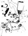
- FIG. 1 demonstrates the most basic working principle of the invention.
- the adhesive tape cutting unit 1 respectively device respectively system comprises, in particular consists of, three main parts; cutter 10, head 8 and tape 2. They are assembled in said taping machine 1 together.
- the purpose of said cutter 10 is cutting conductive or non-conductive tape, in particular strong adhesive tape 2
- head 8 is separating a carrier layer 6 and said adhesive tape 2 from each other and said separated adhesive tape 2 is feed through the head 8 over the rollers, in particular to pressure pin 22, for coupling with a further means or device.
- adhesive tape 2 with carrier layer 6 are provided as one tape 3.
- Said tape 3 is forwarded via tape supply means 4, in particular into the direction of head 8.
- Head 8 comprises a separation pin 20 for removing said carrier layer 6 from adhesive tape 2.
- Adhesive tape 2 is forwarded by at least one forwarding means, in particular forwarding pin 18 (cf. Fig. 3 ), of head 8.
- Said cutting means 10 can be moved with respect to head 8 in particular by means of an actuator means 12.
- Said cutting means 10 preferably comprises two cutting blades 14, 16, wherein each cutting blade preferably comprises a cutting edge 15, 17. After separation carrier layer 6 is transported via carrier layer transportation means 7 to a receiving means.
- Fig. 2a shows more details of cutting means 10. Furthermore, a preferably specially designed pneumatic actuator respectively movement means which supplies timing in between head 8 and cutter 10 is provided. Timing is important because of tension level on tape. There is preferably one specific point after transferring said strong adhesive tape 2 to a surface of a further device when cutting means 10 ideally cuts the adhesive tape 2 at the best level with respect to tape 2 tension. Thus, special designed head 8 is releasing adhesive tape 2 and separating tape-carrier, and fixing the adhesive tape to TV frame. When one of the sides of said further means, in particular device or frame, is finished the cutting means 10 has a timing with head 8 assembly, when head is detected the edge cutter is cutting said adhesive tape 2.
- Cutting means 10 is preferably a pneumatic scissors with spring turn, in particular with the ability for cutting metal.
- Head 8 separates carrier layer 6 and adhesive tape 2. For this there are preferably three pins one is forcing forward 18 one is for separation 20 and the third one is forwarding carrier back to carrier roller.
- Adhesive tape is a conductive or non-conductive tape. It is preferably used fora EMC control on TV Cell units. Some application both side is conductive some one side is conductive fora cell.
- the present invention preferably proposes one special designed head 8 assembly and one external cutter 10 assembly.
- Adhesive tape 2 and carrier layer 6 are separated and forwarded by means of said head 8 respectively head structure.
- Head structure is designed for non-sticky surface. Because the tape adhesive level is so high separation of adhesive tape 2 and carrier 6 is a big problem on a continuous process.
- the head 8 is constructed with separation pins 20, in particular three or less or more than three separation pins 20, each having a dimeter of preferably 2mm. Said separation pins 20 are preferably located for separating and forwarding the adhesive tape 2.
- Head 8 structure is preferably coated with PTFE, thus adhesive tape 2 cannot stick on this structure and preferably never leaves any adhesives remaining for continuous processing.
- Reference number 38 preferably indicates a force transmission element that causes closing respectively moving of said cutting edges 15, 17 to bring them into contact or close before contact.
- Fig. 2b shows schematically the movement direction of said cutting edges 15, 17 in case of cutting said adhesive tape 2.
- Fig. 3 shows additionally or alternatively a special design head with 30° in horizontal axis 36.
- Said head 8 is preferably aligned in an angle 32 between 15° and 45°, in particular between 25° and 30°, with respect said device surface.
- said adhesive tape is preferably feed in an angle between 15° and 45°, in particular between 25° and 30°.
- a feeding means preferably comprises at least two rollers, in particular an adhesive tape roller for feeding respectively guiding said adhesive tape 2 from a source to said head 8 and a carrier tape roller 7 for feeding respectively guiding said carrier tape 6 after separation from said adhesive tape to a storage means.
- Said separated carrier tape 6 and said provided adhesive tape on said carrier tape 6 are preferably at least sectionally transported in parallel directions.
- Cutting means 10 is preferably attached in an angle 30 of 90° to head 8 position for optimum cutting performance and also or alternatively feeder pins are preferably located in an angle 34 of 90° to head axis. Thus, also cutting means 10 is preferably arranged in an angle of 60° to plane.
- the invention provides a cutter assembly for conductive or non-conductive tape with strong adhesive which is preferably used in TV front frames.
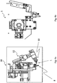
- Fig. 4a shows a robotic unit 26 which comprises respectively hold and/or moves the adhesive tape application unit 1 according to the present invention.
- Fig. 4b shows a side view of the adhesive tape application unit 1 according to the present invention.
- the present invention refers to an adhesive tape application unit 1 for application of adhesive tapes 2, wherein said adhesive tapes 2 are comprising metal particles and/or fibers and/or multiple material layers.
- Said unit 1 preferably comprises at least a tape supply means 4 for supply of adhesive tape 4 on a carrier layer 6 and/or a head 8 for separating said adhesive tape 2 and said carrier layer 6 and for applying said adhesive tape 2 to a device surface and/or a cutting means 10 for cutting said adhesive tape 2, wherein said cutter means 10 is coupled with an actuator means 12 for moving said cutter means 10 with respect to said head 8.
Landscapes
- Replacement Of Web Rolls (AREA)
- Adhesive Tape Dispensing Devices (AREA)
Abstract
Description
- The present invention refers to a strong tape application unit according to
claim 1, a robotic unit according to claim 11, a method for applying strong adhesive tape to a device surface according toclaim 12 and a method for applying strong adhesive tape to at least one part of a TV for assembling said one part to a further part of said TV according toclaim 15. -
EP0492845 discloses a tape cutter capable of cutting a tape completely and enhancing the durability of the cutter blade, a cutter holder is rotated by the engagement of a holder gear portion with a lever gear portion according to the rotation of an operation lever so that a cutter blade is moved toward a tape face. A sliding projection slides upwardly along an inclined face and the cutter holder is moved in the widthwise direction of the tape T. Therefore, the cutter blade presses the tape face and cuts the tape while sliding in the widthwise direction of tape. -
US2005161161A1 discloses a systems and methods for a robotic tape applicator. According toUS2005161161A1 there is provided a system and method for a robotic tape applicator that includes a computer apparatus, a tape applicator apparatus, and an apparatus for holding a work-piece in registration with the tape applicator apparatus for tape application in response to programming data from the computer apparatus. Other components, such as a tape cutting apparatus, a splicing apparatus, adhesion promoter apparatus, and/or optical system can be added to assist and enhance the tape application process. - Robotic tape application heads with six axes robotic assembly is common in industry. However, for applications such as TV frames strong adhesive and conductive tapes are used. These tapes have copper, nickel and strong adhesive layers. Systems in the market have pneumatic horizontal blades in between tape releasing head to cut the tape. Main problem is this kind of releasing head and blade assemblies are unable to cut strong adhesive multilayer tapes and using external cutter is not possible due to current head designs.
- The before mentioned state of the art systems are therefore good for non-strong (weak) adhesives, but not possible with respect to strong adhesive types.
- Thus, prior art has no solution for application of strong adhesive carrier tapes to apply with robotic cutter.
- Therefore, it is the object of the present invention to provide an adhesive tape application unit, a method for applying adhesive tapes and a robotic arm unit with advanced properties in view of cutting strong tapes.
- The before mentioned object is solved by an adhesive tape application unit for application of adhesive tapes according to
claim 1. The adhesive tape application unit according to the present invention preferably comprises at least a tape supply means for supply of adhesive tape on a carrier layer, a head for separating said adhesive tape and said carrier layer and for applying said adhesive tape to a device surface and a cutter means for cutting said adhesive tape, wherein said cutter means is coupled with an actuator means for moving said cutter means with respect to said head. - Said adhesive tapes are highly preferably comprising metal particles and/or fibers and/or multiple material layers. Thus, said tapes are in particular strong tapes.
- Hence, tape used according to the invention is strong adhesive type tape, strong adhesive is generally used term in market which means that it has metal particles (nickel - copper) and/or fibers inside the tape. Non-strong (weak) adhesive means that adhesives without these components (metal.particles and fibers).
- This solution is beneficial since head and cutting means can be moved with respect to each other, thus adhesive tape application unit can be cleaned more easily since said parts can be separated from each other. Furthermore, the position between cutting means and head can be adapted in dependency of production requirements and said cutting means can be much larger since required force transformation or transmission elements of said cutting means can be larger.
- Further preferred embodiments are subject-matter of dependent claims and/or of the following specification parts.
- According to a preferred embodiment of said invention said cutter means comprises two cutting blades each having a cutting edge for cutting said adhesive tape, wherein the cutting edges of said cutting blades are arranged in parallel to each other and are linearly movable between a closed situation and an open situation, wherein said cutting edges are applying pressure to each other in said closed situation and wherein said cutting edges are spaced apart from each other in said open situation. It is also conceivable that just one cutting blade is provided, wherein the other cutting blade is replaced by a counter surface for holding said tape.
- Said actuator means is according to a further preferred embodiment of the present invention able to position said cutting means with respect to said adhesive tape in such a manner that forces applied by said cutting means onto said adhesive means are aligned in an angle between 70° and 110°, in particular 90°, with respect to the surface of said adhesive tape. This embodiment is beneficial since cutting forces are homogeneously applied to said tape due to these features. In particular deformations occurring during cutting are reduced due to this feature.
- Said actuator means is according to a further preferred embodiment of the present invention able to position said cutting means with respect to said adhesive tape in such a manner that each cutting part of each cutting edge fully contacts said adhesive tape at the same time, wherein said cutting edges can be brought in contact with said adhesive tape at the same time or one after another. This embodiment is beneficial since cutting can be carried out in a very precise manner, thus the amount of tape can be reduced while the adhesive coupling of parts to be joined has a better quality.
- According to another preferred embodiment of the present invention said cutting means comprises at least one spring for moving said cutting blades from said closed situation into said open situation and/or a pneumatic actuator for moving said cutting blades from said open situation into said closed situation. This embodiment is beneficial since, forces applied by a pneumatic actuator can be released very fast and easily, thus forces applied by said spring can automatically cause a movement of said cutting blades from said closed situation (cutting situation) into said open situation (tape movement situation).
- Head comprises according to a further preferred embodiment of the present invention at least one pin or exactly one pin or at least two pins or exactly two pins or at least three pins or exactly three pins or up to 2, 3, 4, 5 pins. One pin or multiple pins can be forwarding pin/s, which is/are preferably arranged for forwarding said adhesive tape, in particular into the direction of said cutter means or said device surface. One further or alternative pin can be a separation pin. The separation pin is preferably arranged for separating said adhesive tape from a carrier, in particular a foil-like carrier. One further or alternative pin can be a pressure pin for applying pressure to said adhesive tape for applying it to said device surface. All pins are preferably arranged with respect to each other in predefined and fix positions.
- Said separation pin has according to a further preferred embodiment of the present invention a diameter of less than 20mm, in particular of less than 10mm or less than 5mm or less than 3mm, like 2mm, wherein a carrier tape transfer means is preferably provided for transferring said separated carrier tape to a preferably rotatable receiving means. This embodiment is beneficial since said carrier tape can be removed in a reliable and fast manner. Furthermore, said carrier tape does not disturb further processing of said device, since said carrier tape is received by said receiving means.
- Said pressure pin comprises according to a further preferred embodiment of the present invention at least one bearing, in particular a roller bearing, wherein said pressure pin is rotatable due to said bearing. This embodiment is beneficial since sliding friction between said adhesive tape and said pressure pin can be reduced respectively avoided.
- At least one of said pins, in particular said forwarding respectively feeder pin and/or said separation pin and/or said pressure pin, and/or at least one of said cutting blades is according to a further preferred embodiment of the present invention at least in some parts, in particular in most parts of its surface or fully, coated, in particular coated with a material or material mix having an approximate coefficient of friction lower than 0,7 or lower than 0,5 or lower than 0,2 or lower than 0,1, in case said two coated surfaces of said blades are engaging with each other. The coating material is preferably PTFE (Teflon).
- The before mentioned object is also solved by a robotic unit according to claim 11. Said robotic unit preferably has at least one arm, wherein said arm is movable in six directions, wherein one adhesive tape application unit according to any of the herein described adhesive tape application units is coupled to said arm. This solution is beneficial, since very precise and fast application of tape to device surfaces can be carried out.
- The before mentioned object is also solved by a method for applying strong adhesive tape to a device surface according to
claim 12. Said method for applying strong adhesive tape to a device surface preferably comprises at least the steps: Supplying adhesive tape on a carrier layer; Separating said adhesive tape and said carrier layer with a separation pin of a head; Applying said adhesive tape to a device surface with a pressure pin of said head and Cutting said adhesive tape with a cutting means, wherein said cutter means is coupled with an actuator means and moved by said actuator means with respect to said head. This solution is beneficial, since strong adhesive tapes can be utilized in automated production processes for the first time, without a need for cleaning said cutting means or amending the orientation of said tape after each application of a piece of said strong adhesive tape to a device surface. - Said cutting means is according to a preferred embodiment of the present invention operated for cutting said adhesive tape in dependency of a predefined time after applying a tape to a further means and/or wherein said cutting means is operated for cutting said adhesive tape in dependency of a tension of said adhesive tape. Tension of said adhesive tape is preferably measured by a detection unit, in particular a force sensor. This embodiment is beneficial since pieces of said tape are not just applied to a device surface in dependency of position respectively location parameters, it is thus possible to tension said tape according to predefined parameter for even better properties of the later adhesive connection between joined device parts.
- The before mentioned object is also solved by a method for applying strong adhesive tape to at least one part of a TV for assembling said one part to a further part of said TV according to
claim 15. Said method for applying strong adhesive tape to at least one part of a TV for assembling said one part to a further part of said TV preferably comprises the steps: Supplying adhesive tape on a carrier layer; Separating said adhesive tape and said carrier layer with a separation pin of a head; Applying said adhesive tape to said TV part with a pressure pin of said head and Cutting said adhesive tape with a cutting means, wherein said cutter means is coupled with an actuator means and moved by said actuator means with respect to said head. Thus, this invention is particular preferable for TV front EMI shielding tapes, but equally applicable for all conductive and non-conductive tapes with double sided strong adhesive. - Further benefits, goals and features of the present invention will be described by the following specification of the attached figures, in which components of the invention are exemplarily illustrated. Components of the devices and method according to the inventions, which match at least essentially with respect to their function can be marked with the same reference sign, wherein such components do not have to be marked or described in all figures.
- The invention is just exemplarily described with respect to the attached figures in the following.
-
- Fig. 1
- shows schematically a strong adhesive tape cutting unit according to the present invention;
- Fig. 2a
- shows schematically a further view on said strong adhesive tape cutting unit according to
fig. 1 ; - Fig.2b
- shows schematically the direction of force introduction into said strong adhesive tape during cutting;
- Fig. 3
- shows a further schematically illustration of said strong adhesive tape cutting unit according to the present invention and
- Fig. 4a
- shows a further schematically illustration of a strong adhesive tape cutting unit according to the present invention, wherein said cutting means is moved with respect to the cutting position; and
- Fig. 4b
- shows schematically a further illustration of said strong adhesive tape cutting unit according to the present invention.
-
Figure 1 . demonstrates the most basic working principle of the invention. The adhesivetape cutting unit 1 respectively device respectively system comprises, in particular consists of, three main parts;cutter 10,head 8 andtape 2. They are assembled in saidtaping machine 1 together. The purpose of saidcutter 10 is cutting conductive or non-conductive tape, in particular strongadhesive tape 2,head 8 is separating acarrier layer 6 and saidadhesive tape 2 from each other and said separatedadhesive tape 2 is feed through thehead 8 over the rollers, in particular to pressurepin 22, for coupling with a further means or device. As could be seen fromfig. 1 adhesive tape 2 withcarrier layer 6 are provided as one tape 3. Said tape 3 is forwarded via tape supply means 4, in particular into the direction ofhead 8.Head 8 comprises aseparation pin 20 for removing saidcarrier layer 6 fromadhesive tape 2.Adhesive tape 2 is forwarded by at least one forwarding means, in particular forwarding pin 18 (cf.Fig. 3 ), ofhead 8. Said cutting means 10 can be moved with respect tohead 8 in particular by means of an actuator means 12. Said cutting means 10 preferably comprises two cuttingblades cutting edge separation carrier layer 6 is transported via carrier layer transportation means 7 to a receiving means. -
Fig. 2a shows more details of cutting means 10. Furthermore, a preferably specially designed pneumatic actuator respectively movement means which supplies timing in betweenhead 8 andcutter 10 is provided. Timing is important because of tension level on tape. There is preferably one specific point after transferring said strongadhesive tape 2 to a surface of a further device when cutting means 10 ideally cuts theadhesive tape 2 at the best level with respect totape 2 tension. Thus, special designedhead 8 is releasingadhesive tape 2 and separating tape-carrier, and fixing the adhesive tape to TV frame. When one of the sides of said further means, in particular device or frame, is finished the cutting means 10 has a timing withhead 8 assembly, when head is detected the edge cutter is cutting saidadhesive tape 2. - Cutting means 10 is preferably a pneumatic scissors with spring turn, in particular with the ability for cutting metal.
-
Head 8 separatescarrier layer 6 andadhesive tape 2. For this there are preferably three pins one is forcing forward 18 one is forseparation 20 and the third one is forwarding carrier back to carrier roller. - Adhesive tape is a conductive or non-conductive tape. It is preferably used fora EMC control on TV Cell units. Some application both side is conductive some one side is conductive fora cell.
- As could be identified in
Fig. 2a the present invention preferably proposes one special designedhead 8 assembly and oneexternal cutter 10 assembly. -
Adhesive tape 2 andcarrier layer 6 are separated and forwarded by means of saidhead 8 respectively head structure. Head structure is designed for non-sticky surface. Because the tape adhesive level is so high separation ofadhesive tape 2 andcarrier 6 is a big problem on a continuous process. Thehead 8 is constructed with separation pins 20, in particular three or less or more than threeseparation pins 20, each having a dimeter of preferably 2mm. Said separation pins 20 are preferably located for separating and forwarding theadhesive tape 2. Onhead 8 structure there is also aroller pin 22 which presses on theadhesive tape 2 to stick on a surface of a further means respectively device. It has preferably a very small bearing inside to keep constant rolling over surface.Head 8 structure is preferably coated with PTFE, thusadhesive tape 2 cannot stick on this structure and preferably never leaves any adhesives remaining for continuous processing. -
Reference number 38 preferably indicates a force transmission element that causes closing respectively moving of said cutting edges 15, 17 to bring them into contact or close before contact. -
Fig. 2b shows schematically the movement direction of said cutting edges 15, 17 in case of cutting saidadhesive tape 2. -
Fig. 3 shows additionally or alternatively a special design head with 30° inhorizontal axis 36. Saidhead 8 is preferably aligned in anangle 32 between 15° and 45°, in particular between 25° and 30°, with respect said device surface. Thus, said adhesive tape is preferably feed in an angle between 15° and 45°, in particular between 25° and 30°. A feeding means preferably comprises at least two rollers, in particular an adhesive tape roller for feeding respectively guiding saidadhesive tape 2 from a source to saidhead 8 and acarrier tape roller 7 for feeding respectively guiding saidcarrier tape 6 after separation from said adhesive tape to a storage means. Said separatedcarrier tape 6 and said provided adhesive tape on saidcarrier tape 6 are preferably at least sectionally transported in parallel directions. - Cutting means 10 is preferably attached in an
angle 30 of 90° tohead 8 position for optimum cutting performance and also or alternatively feeder pins are preferably located in anangle 34 of 90° to head axis. Thus, also cuttingmeans 10 is preferably arranged in an angle of 60° to plane. - Thus, the invention provides a cutter assembly for conductive or non-conductive tape with strong adhesive which is preferably used in TV front frames.
-
Fig. 4a shows arobotic unit 26 which comprises respectively hold and/or moves the adhesivetape application unit 1 according to the present invention. -
Fig. 4b shows a side view of the adhesivetape application unit 1 according to the present invention. - Therefore, the present invention refers to an adhesive
tape application unit 1 for application ofadhesive tapes 2, wherein saidadhesive tapes 2 are comprising metal particles and/or fibers and/or multiple material layers.Said unit 1 preferably comprises at least a tape supply means 4 for supply ofadhesive tape 4 on acarrier layer 6 and/or ahead 8 for separating saidadhesive tape 2 and saidcarrier layer 6 and for applying saidadhesive tape 2 to a device surface and/or a cutting means 10 for cutting saidadhesive tape 2, wherein said cutter means 10 is coupled with an actuator means 12 for moving said cutter means 10 with respect to saidhead 8. -
- 1
- adhesive tape application unit
- 2
- adhesive tape
- 3
- adhesive tape with carrier layer
- 4
- tape supply means
- 6
- carrier layer
- 7
- carrier layer transportation means
- 8
- head
- 10
- cutting means
- 12
- actuator means
- 14
- first cutting blade
- 15
- first cutting edge
- 16
- second cutting blade
- 17
- second cutting edge
- 18
- forwarding pin
- 20
- separation pin
- 22
- pressure pin
- 24
- carrier layer transfer means
- 26
- robotic unit
- 30
- Angle between cutter and tape is most preferable 90° (possible 85° - 90°)
- 32
- Head to horizontal frame is located 30° most preferably (25° - 30° possible)
- 34
- Feeder pins are located 90°
- 36
- horizontal plane
- 38
- force transmission element
Claims (15)
- Adhesive tape application unit (1) for application of adhesive tapes (2), wherein said adhesive tapes (2) are comprising metal particles and/or fibers and/or multiple material layers,
at least comprising
a tape supply means (4) for supply of adhesive tape (4) on a carrier layer (6)
a head (8) for separating said adhesive tape (2) and said carrier layer (6) and for applying said adhesive tape (2) to a device surface and
a cutting means (10) for cutting said adhesive tape (2),
wherein said cutter means (10) is coupled with an actuator means (12) for moving said cutter means (10) with respect to said head (8). - Adhesive tape application unit according to claim 1,
characterized in that
said cutting means (10) comprises two cutting blades (14, 16) each having a cutting edge (15, 17) for cutting said adhesive tape (2), wherein the cutting edges (15, 17) of said cutting blades (14, 16) are arranged in parallel to each other and are linearly movable between a closed situation and an open situation, wherein said cutting edges (15, 17) are applying pressure to each other in said closed situation and wherein said cutting edges (15, 17) are spaced apart from each other in said open situation. - Adhesive tape application unit according to claim 1 or 2,
characterized in that
said actuator means (12) is able to position said cutting means (10) with respect to said adhesive tape (2) in such a manner that forces applied by said cutting means (10) onto said adhesive tape (2) are aligned in an angle between 70° and 110°, in particular 90°, with respect to the surface of said adhesive tape (2). - Adhesive tape application unit according to claim 2 or 3,
characterized in that
said actuator means (12) is able to position said cutting means (10) with respect to said adhesive tape (2) in such a manner that each cutting part of each cutting edge (15, 17) fully contacts said adhesive tape (2) at the same time. - Adhesive tape application unit according to any of the before mentioned claims 2 to 4, characterized in that
said cutting means (10) comprises at least one spring for moving said cutting blades (14, 16) from said closed situation into said open situation and a pneumatic actuator for moving said cutting blades (14, 16) from said open situation into said closed situation. - Adhesive tape application unit according to any of the before mentioned claims, characterized in that
said head (8) comprises at least three pins,
wherein one forwarding pin (18) is arranged for forwarding said adhesive tape (2),
wherein one separation pin (20) is arranged for separating said adhesive tape (2) from a carrier layer (6) and
wherein one pressure pin (22) is arranged for applying pressure to said adhesive tape (2) for applying it to said device surface. - Adhesive tape application unit according to claim 6,
characterized in that
said separation pin (20) has a diameter of less than 20mm, in particular of less than 10mm or less than 5mm or less than 3mm, like 2mm, wherein a carrier layer transfer means (24) is provided for transferring said separated carrier layer (6) to a rotatable receiving means. - Adhesive tape application unit according to claim 6 or 7,
characterized in that
said pressure pin (22) comprises at least one bearing, wherein said pressure pin (22) is rotatable due to said bearing. - Adhesive tape application unit according to any of the before mentioned claims,
characterized in that
said head (8) is aligned in an angle between 15° and 45°, in particular between 25° and 30°, with respect said device surface. - Adhesive tape application unit according to any of the before mentioned claims,
characterized in that
at least one of said pins (18, 20, 22), in particular said forwarding pin (18) and/or said separation pin (20) and/or said pressure pin (22),
and/or
at least one of said cutting blades (14, 16)
is at least in some parts, in particular in most parts of its surface or fully, coated, in particular with a material having an approximate coefficient of friction lower than 0,7 or lower than 0,5 or lower than 0,2 or lower than 0,1. - Robotic unit (26) having at least one arm,
wherein said arm is movable in six directions,
wherein one adhesive tape application unit (1) according to any of the before mentioned claims is coupled to said arm. - Method for applying strong adhesive tape to a device surface,
at least comprising the steps:Supplying adhesive tape (2) on a carrier layer (6);Separating said adhesive tape (2) and said carrier layer (6) with a separation pin (20) of a head (8);Applying said adhesive tape (2) to a device surface with a pressure pin (22) of said head (8);andCutting said adhesive tape (2) with a cutting means (10),wherein said cutting means (10) is coupled with an actuator means (12) and moved by said actuator means (12) with respect to said head (8). - Method for applying strong adhesive tape to a device surface according to claim 12,
characterized in that
said cutting means (10) is operated for cutting said adhesive tape (2) in dependency of a predefined time after applying a tape to a further means and/or wherein said cutting means (10) is operated for cutting said adhesive tape (2) in dependency of a tension of said adhesive tape (2). - Method for applying strong adhesive tape to a device surface according to claim 12,
characterized in that
tension of said adhesive tape (2) is preferably measured by a detection unit, in particular a force sensor. - Method for applying strong adhesive tape (2) to at least one part of a TV for assembling said one part to a further part of said TV,
at least comprising the steps:Supplying adhesive tape (2) on a carrier layer (6);Separating said adhesive tape (2) and said carrier layer (6) with a separation pin (20) of a head (8);Applying said adhesive tape (2) to said TV part with a pressure pin (22) of said head (8);andCutting said adhesive tape (8) with a cutting means (10),wherein said cutting means (10) is coupled with an actuator means (12) and moved by said actuator means (12) with respect to said head (8).
Priority Applications (2)
| Application Number | Priority Date | Filing Date | Title |
|---|---|---|---|
| EP16206757.3A EP3339228A1 (en) | 2016-12-23 | 2016-12-23 | Device and method for application and cutting of strong adhesive tapes |
| TR2017/02781A TR201702781A2 (en) | 2016-12-23 | 2017-02-23 | DEVICE AND METHOD FOR APPLICATION AND CUTTING RESISTANT ADHESIVE TAPES |
Applications Claiming Priority (1)
| Application Number | Priority Date | Filing Date | Title |
|---|---|---|---|
| EP16206757.3A EP3339228A1 (en) | 2016-12-23 | 2016-12-23 | Device and method for application and cutting of strong adhesive tapes |
Publications (1)
| Publication Number | Publication Date |
|---|---|
| EP3339228A1 true EP3339228A1 (en) | 2018-06-27 |
Family
ID=57681421
Family Applications (1)
| Application Number | Title | Priority Date | Filing Date |
|---|---|---|---|
| EP16206757.3A Withdrawn EP3339228A1 (en) | 2016-12-23 | 2016-12-23 | Device and method for application and cutting of strong adhesive tapes |
Country Status (2)
| Country | Link |
|---|---|
| EP (1) | EP3339228A1 (en) |
| TR (1) | TR201702781A2 (en) |
Citations (4)
| Publication number | Priority date | Publication date | Assignee | Title |
|---|---|---|---|---|
| EP0155904A1 (en) * | 1984-02-17 | 1985-09-25 | Ciba-Geigy Ag | Device for sticking an adhesive tape to the edge of a plate, especially of a metal plate |
| EP0492845A1 (en) | 1990-12-06 | 1992-07-01 | Brother Kogyo Kabushiki Kaisha | Tape cutter |
| WO1995029116A1 (en) * | 1994-04-26 | 1995-11-02 | Massey University | Improvements relating to application of adhesive tape |
| US20050161161A1 (en) | 2002-03-05 | 2005-07-28 | Sharp Terrance M. | Systems and methods for a robotic tape applicator |
-
2016
- 2016-12-23 EP EP16206757.3A patent/EP3339228A1/en not_active Withdrawn
-
2017
- 2017-02-23 TR TR2017/02781A patent/TR201702781A2/en unknown
Patent Citations (4)
| Publication number | Priority date | Publication date | Assignee | Title |
|---|---|---|---|---|
| EP0155904A1 (en) * | 1984-02-17 | 1985-09-25 | Ciba-Geigy Ag | Device for sticking an adhesive tape to the edge of a plate, especially of a metal plate |
| EP0492845A1 (en) | 1990-12-06 | 1992-07-01 | Brother Kogyo Kabushiki Kaisha | Tape cutter |
| WO1995029116A1 (en) * | 1994-04-26 | 1995-11-02 | Massey University | Improvements relating to application of adhesive tape |
| US20050161161A1 (en) | 2002-03-05 | 2005-07-28 | Sharp Terrance M. | Systems and methods for a robotic tape applicator |
Also Published As
| Publication number | Publication date |
|---|---|
| TR201702781A2 (en) | 2018-07-23 |
Similar Documents
| Publication | Publication Date | Title |
|---|---|---|
| KR101865619B1 (en) | A tape feeder | |
| US20110290090A1 (en) | Robot system and method of manufacturing processed product | |
| JP6296482B2 (en) | Supply device with automatic splicing device | |
| KR20150041521A (en) | Automatic system for attaching label | |
| EP2976209B1 (en) | Film-embossing apparatus | |
| CN212795925U (en) | Circuit board tectorial membrane cutting equipment | |
| WO2015177854A1 (en) | Lead component mounting apparatus and lead component mounting method | |
| WO2015136732A1 (en) | Cutting device and cutting method | |
| JP2018111575A (en) | Tape sticking cassette and tape sticking device | |
| KR101871939B1 (en) | An apparatus for handling end portion of tape | |
| US8562778B2 (en) | Tape adhering apparatus and tape adhering method | |
| JP2012209395A (en) | Sticking device and sticking method of adhesive tape | |
| JP5341648B2 (en) | Sheet sticking device and sticking method | |
| EP4574359A1 (en) | Tape affixing device | |
| US10246936B2 (en) | Masking systems and methods | |
| JP3204581U (en) | Slide fastener manufacturing equipment | |
| JP6232584B2 (en) | Tape cutter for splicing tape | |
| DE112006002113T5 (en) | Foil adhesive device and adhesive method | |
| TR201702781A2 (en) | DEVICE AND METHOD FOR APPLICATION AND CUTTING RESISTANT ADHESIVE TAPES | |
| JP6738409B2 (en) | Parts feeder | |
| JP5418534B2 (en) | ACF sticking device | |
| JP2011068414A (en) | Label sticking apparatus | |
| CN221394275U (en) | Tectorial membrane device and letter sorting tectorial membrane equipment | |
| JP2014143037A (en) | Terminal conveying system, terminal crimping system, and terminal conveying method | |
| JP6353885B2 (en) | Rotation position adjustment device |
Legal Events
| Date | Code | Title | Description |
|---|---|---|---|
| PUAI | Public reference made under article 153(3) epc to a published international application that has entered the european phase |
Free format text: ORIGINAL CODE: 0009012 |
|
| STAA | Information on the status of an ep patent application or granted ep patent |
Free format text: STATUS: THE APPLICATION HAS BEEN PUBLISHED |
|
| AK | Designated contracting states |
Kind code of ref document: A1 Designated state(s): AL AT BE BG CH CY CZ DE DK EE ES FI FR GB GR HR HU IE IS IT LI LT LU LV MC MK MT NL NO PL PT RO RS SE SI SK SM TR |
|
| AX | Request for extension of the european patent |
Extension state: BA ME |
|
| STAA | Information on the status of an ep patent application or granted ep patent |
Free format text: STATUS: REQUEST FOR EXAMINATION WAS MADE |
|
| 17P | Request for examination filed |
Effective date: 20181213 |
|
| RBV | Designated contracting states (corrected) |
Designated state(s): AL AT BE BG CH CY CZ DE DK EE ES FI FR GB GR HR HU IE IS IT LI LT LU LV MC MK MT NL NO PL PT RO RS SE SI SK SM TR |
|
| STAA | Information on the status of an ep patent application or granted ep patent |
Free format text: STATUS: EXAMINATION IS IN PROGRESS |
|
| 17Q | First examination report despatched |
Effective date: 20201002 |
|
| STAA | Information on the status of an ep patent application or granted ep patent |
Free format text: STATUS: THE APPLICATION IS DEEMED TO BE WITHDRAWN |
|
| 18D | Application deemed to be withdrawn |
Effective date: 20210213 |