EP3339225A1 - Reel holder - Google Patents
Reel holder Download PDFInfo
- Publication number
- EP3339225A1 EP3339225A1 EP17205084.1A EP17205084A EP3339225A1 EP 3339225 A1 EP3339225 A1 EP 3339225A1 EP 17205084 A EP17205084 A EP 17205084A EP 3339225 A1 EP3339225 A1 EP 3339225A1
- Authority
- EP
- European Patent Office
- Prior art keywords
- reel
- transceiver
- tag
- filling machine
- holder
- Prior art date
- Legal status (The legal status is an assumption and is not a legal conclusion. Google has not performed a legal analysis and makes no representation as to the accuracy of the status listed.)
- Granted
Links
Images


Classifications
-
- B—PERFORMING OPERATIONS; TRANSPORTING
- B65—CONVEYING; PACKING; STORING; HANDLING THIN OR FILAMENTARY MATERIAL
- B65H—HANDLING THIN OR FILAMENTARY MATERIAL, e.g. SHEETS, WEBS, CABLES
- B65H75/00—Storing webs, tapes, or filamentary material, e.g. on reels
- B65H75/02—Cores, formers, supports, or holders for coiled, wound, or folded material, e.g. reels, spindles, bobbins, cop tubes, cans, mandrels or chucks
- B65H75/18—Constructional details
- B65H75/182—Identification means
-
- B—PERFORMING OPERATIONS; TRANSPORTING
- B65—CONVEYING; PACKING; STORING; HANDLING THIN OR FILAMENTARY MATERIAL
- B65B—MACHINES, APPARATUS OR DEVICES FOR, OR METHODS OF, PACKAGING ARTICLES OR MATERIALS; UNPACKING
- B65B41/00—Supplying or feeding container-forming sheets or wrapping material
- B65B41/12—Feeding webs from rolls
-
- B—PERFORMING OPERATIONS; TRANSPORTING
- B65—CONVEYING; PACKING; STORING; HANDLING THIN OR FILAMENTARY MATERIAL
- B65B—MACHINES, APPARATUS OR DEVICES FOR, OR METHODS OF, PACKAGING ARTICLES OR MATERIALS; UNPACKING
- B65B57/00—Automatic control, checking, warning, or safety devices
-
- B—PERFORMING OPERATIONS; TRANSPORTING
- B65—CONVEYING; PACKING; STORING; HANDLING THIN OR FILAMENTARY MATERIAL
- B65B—MACHINES, APPARATUS OR DEVICES FOR, OR METHODS OF, PACKAGING ARTICLES OR MATERIALS; UNPACKING
- B65B57/00—Automatic control, checking, warning, or safety devices
- B65B57/02—Automatic control, checking, warning, or safety devices responsive to absence, presence, abnormal feed, or misplacement of binding or wrapping material, containers, or packages
-
- B—PERFORMING OPERATIONS; TRANSPORTING
- B65—CONVEYING; PACKING; STORING; HANDLING THIN OR FILAMENTARY MATERIAL
- B65H—HANDLING THIN OR FILAMENTARY MATERIAL, e.g. SHEETS, WEBS, CABLES
- B65H16/00—Unwinding, paying-out webs
- B65H16/02—Supporting web roll
- B65H16/06—Supporting web roll both-ends type
-
- B—PERFORMING OPERATIONS; TRANSPORTING
- B65—CONVEYING; PACKING; STORING; HANDLING THIN OR FILAMENTARY MATERIAL
- B65B—MACHINES, APPARATUS OR DEVICES FOR, OR METHODS OF, PACKAGING ARTICLES OR MATERIALS; UNPACKING
- B65B2210/00—Specific aspects of the packaging machine
- B65B2210/04—Customised on demand packaging by determining a specific characteristic, e.g. shape or height, of articles or material to be packaged and selecting, creating or adapting a packaging accordingly, e.g. making a carton starting from web material
-
- B—PERFORMING OPERATIONS; TRANSPORTING
- B65—CONVEYING; PACKING; STORING; HANDLING THIN OR FILAMENTARY MATERIAL
- B65H—HANDLING THIN OR FILAMENTARY MATERIAL, e.g. SHEETS, WEBS, CABLES
- B65H2553/00—Sensing or detecting means
- B65H2553/52—RFID sensor
-
- B—PERFORMING OPERATIONS; TRANSPORTING
- B65—CONVEYING; PACKING; STORING; HANDLING THIN OR FILAMENTARY MATERIAL
- B65H—HANDLING THIN OR FILAMENTARY MATERIAL, e.g. SHEETS, WEBS, CABLES
- B65H2701/00—Handled material; Storage means
- B65H2701/10—Handled articles or webs
- B65H2701/11—Dimensional aspect of article or web
- B65H2701/113—Size
- B65H2701/1133—Size of webs
-
- B—PERFORMING OPERATIONS; TRANSPORTING
- B65—CONVEYING; PACKING; STORING; HANDLING THIN OR FILAMENTARY MATERIAL
- B65H—HANDLING THIN OR FILAMENTARY MATERIAL, e.g. SHEETS, WEBS, CABLES
- B65H2801/00—Application field
- B65H2801/81—Packaging machines
Definitions
- the present invention generally relates to the field of mechanical holders or supports for rotating reels. More particularly, the present invention relates to a reel holder for reels of packaging material, a filling machine system and a filling machine.
- packages are often made by carton based multi-layer laminates that are folded, filled with content, and sealed into packages.
- the packaging material e.g. a complex multi-layer packaging material
- each roll or reel contains packaging material for a large number of packages, often thousands of packages.
- the large reels with packaging material are pre-printed according to the food product that is filled into the package.
- the multi-layer packaging material also contains different layers depending on the product that is intended to be stored in the package.
- the reels with packaging material are often fed to the packing or filling machine by a so called automatic splicing unit comprising two mandrels each intended to receive a reel of packaging material.
- the automatic splicing unit will automatically splice the beginning of the packaging material of the second reel onto the end of the packaging material of the first reel. If an incorrect reel is introduced into the automatic splicing unit and the incorrect reel is used, the filling machine has to be stopped, and it has to be cleaned before starting again, which may invoke large costs and result in a lot of wasted product.
- an improved system for handling packaging materials would be advantageous and in particular allowing for avoiding more of the above mentioned problems and compromises, including reducing the risk of using a reel with incorrect packaging material.
- examples of the present invention preferably seeks to mitigate, alleviate or eliminate one or more deficiencies, disadvantages or issues in the art, such as the above-identified, singly or in any combination by providing a device according to the appended patent claims.
- a reel holder comprising an opening for receiving and holding a reel provided with packaging material, and a transceiver adapted to communicate with a tag provided in said reel in order to receive information stored in said tag.
- a filling machine system comprising a reel holder according to the first aspect and a reel provided with a tag, said reel holder comprising a transceiver adapted to communicate with said tag in order to receive information stored in said tag.
- Some examples of the disclosure provide for an improved reel holder that facilitates identification of a packaging material provided on a reel.
- Some examples of the disclosure provide for a reel holder that allows a more accurate or reliable identification of a packaging material provided on a reel.
- Some examples of the disclosure provide for increased accuracy in identifying of a packaging material while provided on a rotating reel.
- Some examples of the disclosure provide for a more compact system for identifying a packaging material provided on a reel.
- Some examples of the disclosure provide for a more robust reel holder while also being able to allow identification of a packaging material provided on a reel.
- Some examples of the disclosure provide for an improved reel holder that is easier to implement in existing filling machines.
- Some examples of the disclosure provide for a less costly implementation of a packaging material identification system on existing filling machines.
- Some examples of the disclosure provide for an improved integration of a packaging material identification system in an existing communication network controlling a filling machine.
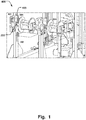
- Fig. 1 illustrates a filling machine 400, having mandrels 204 being adapted to carry the reels 200.
- a reel 200 provided with a packaging material 201 is illustrated in Fig. 4 .
- the packaging material 201 is wound up on a central cylinder 205 of the reel 200, and the mandrel 204 is adapted to be inserted into the central cylinder 205 in order to hold the reel 200.
- Each of the mandrels 204 are able to rotate around central axis 203.
- the axis 203 is rotatably received in holders 100 on each side of the respective mandrels 204.
- the holders 100 are mounted in a frame 402 of the filling machine 400, to provide a fixation of the reels 200 in relation to the filling machine 400.
- the packaging material 201 is then transported from the reels 200 into the filling machine 400 to be processed.
- Fig. 2a illustrates a reel holder 100 comprising an opening 101 for receiving and holding a reel 200 provided with packaging material 201.
- the opening 101 may be arranged so that insertion of the axis 203 of the reel 200 is facilitated.
- the opening 101 may comprise a guiding portion 115 having wider opening than the portion 116 of the opening 101 that fixates the axis 203 in its final position.
- the guiding portion 115 may be open outwards in a horizontal direction, as illustrated in Fig. 2a , in order to provide for insertion of the reel 200 from the side.
- the holder 100 may also comprise further guiding surfaces 117, 118, which tapers away from the final position 116 of the axis 203 in order to further guide the axis 203 into the opening 101 and the final position 116 of the holder 101 if needed.
- the holder 100 further comprises a transceiver 102 adapted to communicate with a tag 202 provided in the reel 200 in order to receive information stored in the tag 202.
- This allows for identification of the reel 200, i.e. identification of the packaging material 201 provided on the reel 200, via the holder 100 itself.
- no additional modifications are needed to the filling machine 400, such as incorporating auxiliary equipment to allow for such identification of the packaging material 201, which may be cumbersome to implement in an existing setup, e.g. due to space constrains.
- the communication path with the tag 202 provided in the reel 200 is optimized, since the distance between the transceiver 102 and the tag can be minimized.
- Fig. 1 shows a previous solution where an antenna 401 is placed in the frame of the filling machine 400. This solution increases the distance of the communication path, and is a less reliable solution. Further, due to the mentioned space constrains, the antenna 401 is placed adjacent the holder, and may thereby interfere with the loading of the reel in the filling machine 400.
- Fig. 2b schematically illustrates a view of an internal section of the holder 100 in Fig. 2a .
- the transceiver 102 may thus be positioned internally of the holder 100, and/or the transceiver 102 may be arranged adjacent the surface 111 facing the reel 200 (see Fig. 5 ).
- Fig. 3 illustrates the reel holder 100 and a reel 200, provided with a tag 202, being position in the opening 101 of the holder 100.
- the mandrel 204 is inserted into the cylindrical portion 205 of the reel 200, and the axis 203 of the mandrel 204 is positioned in the opening 101.
- the tag 202 is also illustrated in Fig. 4 , as it is positioned in the cylindrical portion 205 of the reel 200.
- the transceiver 102 can be placed in close vicinity with the mandrel 204 and the cylindrical portion 205 of the reel 200, being provided with the tag 202, to optimize the communication path, without interfering with the loading of the reel 200 into the opening 101 or otherwise occupy unnecessary space in the vicinity of the mandrel 204.
- the transceiver 102 may comprise an antenna 103 being oriented in a predetermined angle, towards the reel 200, determined in dependence of an average signal strength at which the information from the tag 202 is received, when the reel 200 is received and rotating in the opening 101.
- the detection can be made more accurate and reliable.
- the packaging material 201 may comprise a laminate that shields electromagnetic radiation, such as a metallic sheet in the laminate. The optimized angle and position of the antenna 103 thus improves the communication with the tag 202.
- the antenna 103 may have two dipoles 104, 105, placed at an angle apart (v) determined in dependence of an average signal strength at which the information is received by the two dipoles, when the reel 200 is received and rotating in the opening 101.
- Fig. 2b illustrates schematically how the two dipoles are oriented at an angle (v) apart.
- Fig. 5 further illustrates the two dipoles and how the communication path may change as the tag 202 rotates with the reel 200.
- each dipole may be oriented to provide for maximum signal strength in communication with the tag 202.
- the tag 202 is positioned substantially vertically in the reel 200, i.e. in the position denoted with reference 202 in Fig.
- a first dipole 104 may be oriented in an angle to provide the maximum signal with the tag 202 in this position.
- the second dipole 105 may be oriented in an angle to have a maximum signal strength when the tag has rotated 90 degrees, so that it is positioned substantially horizontal in the reel 200, i.e. in the position denoted with reference 202' in Fig. 5 .
- the second dipole 105 will also provide the maximum signal strength when the tag has rotated another 180 degrees, i.e. being positioned in lowermost position in the reel 200.
- the first dipole 104 may be linearly polarized in the horizontal direction
- the second dipole 105 may be linearly polarized in the vertical direction, or vice versa. It is also conceivable that the antenna 103 is circularly polarized.
- the reel holder 100 may comprise an impedance matching circuit 106 connected to the transceiver 102, as schematically illustrated in Fig. 2b .
- the impedance matching circuit 106 may be adapted to couple the transceiver 102 with an external circuit network 107 at a determined impedance.
- the holder 100 may thus comprise the circuit components required to facilitate connection to an existing network of components (schematically denoted 107 in Fig. 2b ), which may have a varying impedance.
- a holder 100 having such self-contained circuit eases the replacement of existing previous holders, and provides for a compact setup.
- the reel holder 100 may comprise an interface unit 108 connected to the transceiver 102.
- the interface unit 108 may be adapted to communicate with the external circuit network 107 via the impedance matching circuit 106.
- the interface unit 108 allows for connecting the holder 100 to external communication via the impedance matching circuit 106.
- the interface unit 108 may comprise a wired or wireless connection interface to the external circuit network 107.
- the holder 100 may further comprise a processing unit 119, connected to the impedance matching circuit 106, the transceiver 102 and the interface unit 108, to control the communication between the holder 100 and the external network 107.
- the transceiver 102 may be integrated into a casing 109 of the holder 100.
- the casing 109 also defines the opening 101 that receives and holds the reel 200. I.e. as mentioned above, the opening 101 is adapted to receive the axle 203 of the mandrel 204 on which the reel 200 is mounted.
- the transceiver 102 may thus be integrated into the casing 102 of the holder 100 itself, which holds the axel 203 of the reel 200. This provides for positioning the transceiver 102 as close to the reel 200 as possible, with the advantages of improving the signal strength and minimizing the occupied space when integrated in a filling machine 400, and further facilitating the integration in existing machines, as further elucidated above.
- the transceiver 102 may be arranged in the casing 109 so that the shortest distance between the reel 200 and the transceiver 102 substantially corresponds to the horizontal spacing 110 between the reel 200 and a side 111 of the reel holder 100 facing the reel 200.
- This is schematically illustrated in Fig. 5 , where it is also shown that the horizontal spacing 110 is defined by the length of a portion 112 of the axle 203 extending between the side 111 of the holder 100 facing the reel 200 and the reel 200 itself.
- the transceiver 102 may thus be arranged close to the surface of the side 111 facing the reel 200.
- the transceiver 102 and related components as discussed above may be fully contained in the casing 109 of the holder 100. It is also conceivable that the transceiver 102 may be at least partly arranged on the surface of the side 111 facing the reel 200, for example having an antenna 103 extending towards the reel 200. And/or the casing 109 may have apertures (not shown) that improve the transmission of signal to the transceiver 102 through the casing 109.
- the transceiver 102 may be arranged in a cavity 113 formed in a monolithic piece 114 of the casing 109.
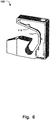
- Fig. 6 illustrates the holder 100 being a solid piece of material 114 in which the cavity 113 has been formed, e.g. by a milling process. This allows for integration of the transceiver 102 in the holder 100 to achieve a compact profile of the holder 100, while maintaining the required structural integrity of the holder 100 to be able to hold the reel 200, which may carry several tons of packaging material 201.
- the information received by the transceiver 102 from the tag 202 may comprise data describing the packaging material 201.
- the packaging material 201 of the current reel 200 mounted in the filling machine 400 matches the particular product that is going to be produced.
- a filling machine system 300 is also provided according to the present disclosure.
- the filling machine system 300 comprises the reel holder 100 as described above, and a reel 200 provided with a tag 202.
- the reel holder 100 comprises the transceiver 102 as described above, being adapted to communicate with the tag 202 of the reel 200 in order to receive information stored in the tag 202.
- the transceiver 102 may be arranged adjacent to the reel 200 and near an axle 203 of the reel 200 such that a radio communication path between the transceiver 102 and the tag 202 is not hindered by the reel 200. This provides for optimizing the communication path, and improving the reliability of the communication, in particular since the reel 200 may be carrying a packaging material 201 comprising a laminate having an electromagnetically shielding material.
- Fig. 3 illustrates the transceiver 102 in the upper part of the holder 100. It is also conceivable that the transceiver 102 is placed in other parts of the holder 100 to optimize the communication path, for example in the middle or lower part of the holder 100.
- the reel 200 may be provided on a mandrel 204 which is manufactured from a radio frequency transparent material.
- the mandrel 204 may be manufactured by a radio frequency transparent material in order to avoid interference of the radio communication between the transceiver 102 and the tag 202.
- the radio frequency transparent material may comprise nylon especially suitable for this purpose.
- the tag 202 may be an RFID tag, such as an HF-tag, a UHF-tag or an NFC-tag.
- the tag 202 may have an antenna (not shown) for receiving an induction radio signal and for sending a response to an induction radio signal.
- the antenna may be arranged under the top side of the tag 202 and cover most of the area of the tag.
- the tag 202 may be rectangular or oblong and may be positioned with its length side perpendicular to the center axis 203 of the reel 200 to optimize the area of the antenna (not shown) of the tag 202 that is exposed to the radio signal from the transceiver 102.
- the filling machine system 300 may be adapted to be arranged in a filling machine 400, and the reel holder 100 may be adapted to be removably fixated in the filling machine 400 in relation to the reel 200. This provides for facilitated integration of the holder 100 in existing filling machines 400, to provide for the above mentioned benefits of the holder 100.
- the filling machine system 300 may be adapted to be arranged in a filling machine 400, and the filling machine system 300 may further comprise a control unit 301, schematically illustrated in Fig. 3 , adapted to control the filling machine 400 based on information retrieved from the tag 202. Accordingly, the process of reading the information stored in the tag 202 and controlling the filling machine 400 based on the information may be completely automated. Should a reel 200 with the wrong type of packaging material be mounted on the mandrel 204 of the filling machine 400 it may be registered by the control unit 301, which in turn could trigger an alarm or the like.
Landscapes
- Engineering & Computer Science (AREA)
- Mechanical Engineering (AREA)
- Containers And Plastic Fillers For Packaging (AREA)
- Basic Packing Technique (AREA)
- Support Of Aerials (AREA)
- Details Of Rigid Or Semi-Rigid Containers (AREA)
- Labeling Devices (AREA)
- Storage Of Web-Like Or Filamentary Materials (AREA)
Abstract
Description
- The present invention generally relates to the field of mechanical holders or supports for rotating reels. More particularly, the present invention relates to a reel holder for reels of packaging material, a filling machine system and a filling machine.
- In the food packaging industry, packages are often made by carton based multi-layer laminates that are folded, filled with content, and sealed into packages. For most food packaging machines, the packaging material, e.g. a complex multi-layer packaging material, is provided in large rolls of packaging material, where each roll or reel contains packaging material for a large number of packages, often thousands of packages. The large reels with packaging material are pre-printed according to the food product that is filled into the package. The multi-layer packaging material also contains different layers depending on the product that is intended to be stored in the package. Some packaging materials are made for fresh products intended to keep chilled and to be consumed in a relatively near future, while other packing materials are intended for packages that are aseptic, in order to store food products for long periods of time. It is thus important that the correct packaging material is used for the intended product, both so that the correct print end up on the correct packaged product, and that the correct type of packaging material is used for the current product. The reels with packaging material are often fed to the packing or filling machine by a so called automatic splicing unit comprising two mandrels each intended to receive a reel of packaging material. When one reel is empty, the automatic splicing unit will automatically splice the beginning of the packaging material of the second reel onto the end of the packaging material of the first reel. If an incorrect reel is introduced into the automatic splicing unit and the incorrect reel is used, the filling machine has to be stopped, and it has to be cleaned before starting again, which may invoke large costs and result in a lot of wasted product. Thus, when handling large volumes of products, it is critical to maintain the matching between the product and the material provided by the reels. Further, previous solutions designed to facilitate the handling of the reels, having various packaging materials, in filling machines producing a variety of different products have been cumbersome to implement in existing filling machine environments and setups. While it would be highly desirable to use an existing setup, to avoid costly rebuilding of the machine, there are often difficulties arising from space constrains in the vicinity of the mandrels holding the reels.
- Hence, an improved system for handling packaging materials would be advantageous and in particular allowing for avoiding more of the above mentioned problems and compromises, including reducing the risk of using a reel with incorrect packaging material.
- Accordingly, examples of the present invention preferably seeks to mitigate, alleviate or eliminate one or more deficiencies, disadvantages or issues in the art, such as the above-identified, singly or in any combination by providing a device according to the appended patent claims.
- According to a first aspect a reel holder is provided comprising an opening for receiving and holding a reel provided with packaging material, and a transceiver adapted to communicate with a tag provided in said reel in order to receive information stored in said tag.
- According to a second aspect a filling machine system is provided comprising a reel holder according to the first aspect and a reel provided with a tag, said reel holder comprising a transceiver adapted to communicate with said tag in order to receive information stored in said tag.
- Further examples of the invention are defined in the dependent claims, wherein features for the second aspect of the disclosure are as for the first aspect mutatis mutandis.
- Some examples of the disclosure provide for an improved reel holder that facilitates identification of a packaging material provided on a reel.
- Some examples of the disclosure provide for a reel holder that allows a more accurate or reliable identification of a packaging material provided on a reel.
- Some examples of the disclosure provide for increased accuracy in identifying of a packaging material while provided on a rotating reel.
- Some examples of the disclosure provide for a more compact system for identifying a packaging material provided on a reel.
- Some examples of the disclosure provide for a more robust reel holder while also being able to allow identification of a packaging material provided on a reel.
- Some examples of the disclosure provide for an improved reel holder that is easier to implement in existing filling machines.
- Some examples of the disclosure provide for a less costly implementation of a packaging material identification system on existing filling machines.
- Some examples of the disclosure provide for an improved integration of a packaging material identification system in an existing communication network controlling a filling machine.
- It should be emphasized that the term "comprises/comprising" when used in this specification is taken to specify the presence of stated features, integers, steps or components but does not preclude the presence or addition of one or more other features, integers, steps, components or groups thereof.
- These and other aspects, features and advantages of which examples of the invention are capable of will be apparent and elucidated from the following description of examples of the present invention, reference being made to the accompanying drawings, in which
-
Fig. 1 is a schematic illustration of an example of a filling machine having a filling machine system of a reel holder and a reel that holds a packaging material; -
Fig. 2a is a schematic illustration of an example of a reel holder; -
Fig. 2b is a schematic illustration of an example of a reel holder as seen inFig. 2a , but with a cut-out to see the interior of the reel holder; -
Fig. 3 is a schematic illustration, in a perspective view, of an example of a reel holder holding a reel; -
Fig. 4 is a schematic illustration of an example of a reel to be held in the reel holder; -
Fig. 5 is a schematic illustration, in a side view, of an example of a reel holder holding a reel; and -
Fig. 6 is a schematic illustration, in a perspective view, of an example of a reel holder with a cut-out to see the interior of the reel holder; - Specific examples of the invention will now be described with reference to the accompanying drawings. This invention may, however, be embodied in many different forms and should not be construed as limited to the examples set forth herein; rather, these examples are provided so that this disclosure will be thorough and complete, and will fully convey the scope of the invention to those skilled in the art. The terminology used in the detailed description of the examples illustrated in the accompanying drawings is not intended to be limiting of the invention. In the drawings, like numbers refer to like elements.
-
Fig. 1 illustrates afilling machine 400, havingmandrels 204 being adapted to carry thereels 200. Areel 200 provided with apackaging material 201 is illustrated inFig. 4 . Thepackaging material 201 is wound up on acentral cylinder 205 of thereel 200, and themandrel 204 is adapted to be inserted into thecentral cylinder 205 in order to hold thereel 200. Each of themandrels 204 are able to rotate aroundcentral axis 203. Theaxis 203 is rotatably received inholders 100 on each side of therespective mandrels 204. Theholders 100 are mounted in aframe 402 of thefilling machine 400, to provide a fixation of thereels 200 in relation to thefilling machine 400. Thepackaging material 201 is then transported from thereels 200 into thefilling machine 400 to be processed. -
Fig. 2a illustrates areel holder 100 comprising an opening 101 for receiving and holding areel 200 provided with packaging material 201.The opening 101 may be arranged so that insertion of theaxis 203 of thereel 200 is facilitated. For example, the opening 101 may comprise a guidingportion 115 having wider opening than theportion 116 of the opening 101 that fixates theaxis 203 in its final position. The guidingportion 115 may be open outwards in a horizontal direction, as illustrated inFig. 2a , in order to provide for insertion of thereel 200 from the side. Theholder 100 may also comprise further guidingsurfaces final position 116 of theaxis 203 in order to further guide theaxis 203 into theopening 101 and thefinal position 116 of theholder 101 if needed. - The
holder 100 further comprises atransceiver 102 adapted to communicate with atag 202 provided in thereel 200 in order to receive information stored in thetag 202. This allows for identification of thereel 200, i.e. identification of thepackaging material 201 provided on thereel 200, via theholder 100 itself. Thus, no additional modifications are needed to thefilling machine 400, such as incorporating auxiliary equipment to allow for such identification of thepackaging material 201, which may be cumbersome to implement in an existing setup, e.g. due to space constrains. Also, by having atransceiver 102 in theholder 100, the communication path with thetag 202 provided in thereel 200 is optimized, since the distance between thetransceiver 102 and the tag can be minimized. This allows for a more accurate and reliable communication between thetransceiver 102 and thetag 202. This is particularly critical in the present application since thereel 200, and consequently also thetag 201, rotates with high speed in order to maintain a high throughput of the fillingmachine 400.Fig. 1 shows a previous solution where anantenna 401 is placed in the frame of the fillingmachine 400. This solution increases the distance of the communication path, and is a less reliable solution. Further, due to the mentioned space constrains, theantenna 401 is placed adjacent the holder, and may thereby interfere with the loading of the reel in the fillingmachine 400. By having aholder 100 comprising thetransceiver 102, the loading of thereel 200 can be facilitated, while maintaining a highly reliable readout signal from thetag 201, even in high speed applications. This advantageously also provides for facilitated upgrades of existingfilling machines 400 to be able to accurately and reliably identify the packaging material used, since only the reel holder needs to be replaced, due to thereel holder 100 incorporating thetransceiver 102.Fig. 2b schematically illustrates a view of an internal section of theholder 100 inFig. 2a . Thetransceiver 102 may thus be positioned internally of theholder 100, and/or thetransceiver 102 may be arranged adjacent thesurface 111 facing the reel 200 (seeFig. 5 ). -
Fig. 3 illustrates thereel holder 100 and areel 200, provided with atag 202, being position in theopening 101 of theholder 100. I.e. themandrel 204 is inserted into thecylindrical portion 205 of thereel 200, and theaxis 203 of themandrel 204 is positioned in theopening 101. Thetag 202 is also illustrated inFig. 4 , as it is positioned in thecylindrical portion 205 of thereel 200. Thus, as seen in the perspective view ofFig. 3 , thetransceiver 102 can be placed in close vicinity with themandrel 204 and thecylindrical portion 205 of thereel 200, being provided with thetag 202, to optimize the communication path, without interfering with the loading of thereel 200 into theopening 101 or otherwise occupy unnecessary space in the vicinity of themandrel 204. - The
transceiver 102 may comprise anantenna 103 being oriented in a predetermined angle, towards thereel 200, determined in dependence of an average signal strength at which the information from thetag 202 is received, when thereel 200 is received and rotating in theopening 101. Thus, by adapting the position of theantenna 103 in dependence of the detected signal strength, which fluctuates as thetag 202 is not stationary but rotates with thereel 200, the detection can be made more accurate and reliable. This is also a particular challenge in the present application since thepackaging material 201 may comprise a laminate that shields electromagnetic radiation, such as a metallic sheet in the laminate. The optimized angle and position of theantenna 103 thus improves the communication with thetag 202. - The
antenna 103 may have twodipoles reel 200 is received and rotating in theopening 101.Fig. 2b illustrates schematically how the two dipoles are oriented at an angle (v) apart.Fig. 5 further illustrates the two dipoles and how the communication path may change as thetag 202 rotates with thereel 200. Thus, each dipole may be oriented to provide for maximum signal strength in communication with thetag 202. For example, as thetag 202 is positioned substantially vertically in thereel 200, i.e. in the position denoted withreference 202 inFig. 5 , afirst dipole 104 may be oriented in an angle to provide the maximum signal with thetag 202 in this position. Thesecond dipole 105 may be oriented in an angle to have a maximum signal strength when the tag has rotated 90 degrees, so that it is positioned substantially horizontal in thereel 200, i.e. in the position denoted with reference 202' inFig. 5 . In this case, thesecond dipole 105 will also provide the maximum signal strength when the tag has rotated another 180 degrees, i.e. being positioned in lowermost position in thereel 200. This will also be the case with respect to thefirst dipole 104, when the tag has rotated 180 degrees from theposition 202 to the corresponding vertical position on the opposite side of thereel 200. Thefirst dipole 104 may be linearly polarized in the horizontal direction, and thesecond dipole 105 may be linearly polarized in the vertical direction, or vice versa. It is also conceivable that theantenna 103 is circularly polarized. - The
reel holder 100 may comprise animpedance matching circuit 106 connected to thetransceiver 102, as schematically illustrated inFig. 2b . Theimpedance matching circuit 106 may be adapted to couple thetransceiver 102 with anexternal circuit network 107 at a determined impedance. Theholder 100 may thus comprise the circuit components required to facilitate connection to an existing network of components (schematically denoted 107 inFig. 2b ), which may have a varying impedance. Aholder 100 having such self-contained circuit eases the replacement of existing previous holders, and provides for a compact setup. - The
reel holder 100 may comprise aninterface unit 108 connected to thetransceiver 102. Theinterface unit 108 may be adapted to communicate with theexternal circuit network 107 via theimpedance matching circuit 106. Thus, theinterface unit 108 allows for connecting theholder 100 to external communication via theimpedance matching circuit 106. Theinterface unit 108 may comprise a wired or wireless connection interface to theexternal circuit network 107. Theholder 100 may further comprise aprocessing unit 119, connected to theimpedance matching circuit 106, thetransceiver 102 and theinterface unit 108, to control the communication between theholder 100 and theexternal network 107. - The
transceiver 102 may be integrated into acasing 109 of theholder 100. Thecasing 109 also defines theopening 101 that receives and holds thereel 200. I.e. as mentioned above, theopening 101 is adapted to receive theaxle 203 of themandrel 204 on which thereel 200 is mounted. Thetransceiver 102 may thus be integrated into thecasing 102 of theholder 100 itself, which holds theaxel 203 of thereel 200. This provides for positioning thetransceiver 102 as close to thereel 200 as possible, with the advantages of improving the signal strength and minimizing the occupied space when integrated in a fillingmachine 400, and further facilitating the integration in existing machines, as further elucidated above. - The
transceiver 102 may be arranged in thecasing 109 so that the shortest distance between thereel 200 and thetransceiver 102 substantially corresponds to thehorizontal spacing 110 between thereel 200 and aside 111 of thereel holder 100 facing thereel 200. This is schematically illustrated inFig. 5 , where it is also shown that thehorizontal spacing 110 is defined by the length of aportion 112 of theaxle 203 extending between theside 111 of theholder 100 facing thereel 200 and thereel 200 itself. By having thetransceiver 102 arranged in thecasing 109 so that the shortest distance between thereel 200 and thetransceiver 102 substantially corresponds to thehorizontal spacing 110, the length of the communication path can be minimized, and the average signal strength can be improved. Thetransceiver 102 may thus be arranged close to the surface of theside 111 facing thereel 200. Thetransceiver 102 and related components as discussed above may be fully contained in thecasing 109 of theholder 100. It is also conceivable that thetransceiver 102 may be at least partly arranged on the surface of theside 111 facing thereel 200, for example having anantenna 103 extending towards thereel 200. And/or thecasing 109 may have apertures (not shown) that improve the transmission of signal to thetransceiver 102 through thecasing 109. - The
transceiver 102 may be arranged in acavity 113 formed in amonolithic piece 114 of thecasing 109.Fig. 6 illustrates theholder 100 being a solid piece ofmaterial 114 in which thecavity 113 has been formed, e.g. by a milling process. This allows for integration of thetransceiver 102 in theholder 100 to achieve a compact profile of theholder 100, while maintaining the required structural integrity of theholder 100 to be able to hold thereel 200, which may carry several tons ofpackaging material 201. - As elucidated above, the information received by the
transceiver 102 from thetag 202 may comprise data describing thepackaging material 201. Thus, it is possible to ascertain that thepackaging material 201 of thecurrent reel 200 mounted in the fillingmachine 400 matches the particular product that is going to be produced. - A filling
machine system 300 is also provided according to the present disclosure. The fillingmachine system 300 comprises thereel holder 100 as described above, and areel 200 provided with atag 202. Thereel holder 100 comprises thetransceiver 102 as described above, being adapted to communicate with thetag 202 of thereel 200 in order to receive information stored in thetag 202. - The
transceiver 102 may be arranged adjacent to thereel 200 and near anaxle 203 of thereel 200 such that a radio communication path between thetransceiver 102 and thetag 202 is not hindered by thereel 200. This provides for optimizing the communication path, and improving the reliability of the communication, in particular since thereel 200 may be carrying apackaging material 201 comprising a laminate having an electromagnetically shielding material.Fig. 3 illustrates thetransceiver 102 in the upper part of theholder 100. It is also conceivable that thetransceiver 102 is placed in other parts of theholder 100 to optimize the communication path, for example in the middle or lower part of theholder 100. - The
reel 200 may be provided on amandrel 204 which is manufactured from a radio frequency transparent material. Themandrel 204 may be manufactured by a radio frequency transparent material in order to avoid interference of the radio communication between thetransceiver 102 and thetag 202. The radio frequency transparent material may comprise nylon especially suitable for this purpose. - The
tag 202 may be an RFID tag, such as an HF-tag, a UHF-tag or an NFC-tag. Typically thetag 202 may have an antenna (not shown) for receiving an induction radio signal and for sending a response to an induction radio signal. The antenna may be arranged under the top side of thetag 202 and cover most of the area of the tag. Thetag 202 may be rectangular or oblong and may be positioned with its length side perpendicular to thecenter axis 203 of thereel 200 to optimize the area of the antenna (not shown) of thetag 202 that is exposed to the radio signal from thetransceiver 102. - The filling
machine system 300 may be adapted to be arranged in a fillingmachine 400, and thereel holder 100 may be adapted to be removably fixated in the fillingmachine 400 in relation to thereel 200. This provides for facilitated integration of theholder 100 in existingfilling machines 400, to provide for the above mentioned benefits of theholder 100. - Thus, the filling
machine system 300 may be adapted to be arranged in a fillingmachine 400, and the fillingmachine system 300 may further comprise acontrol unit 301, schematically illustrated inFig. 3 , adapted to control the fillingmachine 400 based on information retrieved from thetag 202. Accordingly, the process of reading the information stored in thetag 202 and controlling the fillingmachine 400 based on the information may be completely automated. Should a reel 200 with the wrong type of packaging material be mounted on themandrel 204 of the fillingmachine 400 it may be registered by thecontrol unit 301, which in turn could trigger an alarm or the like. - It should be readily understood that the general principle of the above description is applicable to a variety of applications for manufacturing packaging containers where the packaging material varies among a variety of different types of containers, not only for food products.
- The present invention has been described above with reference to specific examples. However, other examples than the above described are equally possible within the scope of the invention. The different features and steps of the invention may be combined in other combinations than those described. The scope of the invention is only limited by the appended patent claims.
- More generally, those skilled in the art will readily appreciate that all parameters, dimensions, materials, and configurations described herein are meant to be exemplary and that the actual parameters, dimensions, materials, and/or configurations will depend upon the specific application or applications for which the teachings of the present invention is/are used.
Claims (15)
- A reel holder (100) comprisingan opening (101) for receiving and holding a reel (200) provided with packaging material (201), anda transceiver (102) adapted to communicate with a tag (202) provided in said reel (200) in order to receive information stored in said tag.
- Reel holder according to claim 1, wherein said transceiver comprises an antenna (103) being oriented in a predetermined angle, towards said reel, determined in dependence of an average signal strength at which said information is received, when said reel is received and rotating in said opening.
- Reel holder according to claim 2, wherein said antenna has two dipoles (104, 105) placed at an angle apart (v) determined in dependence of an average signal strength at which said information is received by said two dipoles, when said reel is received and rotating in said opening.
- Reel holder according to any of claims 1 - 3, wherein said reel holder comprises an impedance matching circuit (106) connected to said transceiver, said impedance matching circuit is adapted to couple the transceiver with an external circuit network (107) at a determined impedance.
- Reel holder according to claim 4, comprising an interface unit (108) connected to said transceiver, said interface unit is adapted to communicate with said external circuit network via said impedance matching circuit.
- Reel holder according to any of claims 1 - 5, wherein said transceiver is integrated into a casing (109) of said holder, said casing defining said opening for receiving and holding said reel, and wherein said opening is adapted to receive an axle (203) of a mandrel (204) on which said reel is mounted, when holding said reel.
- Reel holder according to claim 6, wherein said transceiver is arranged in said casing so that the shortest distance between the reel and the transceiver substantially corresponds to the horizontal spacing (110) between the reel and a side (111) of the reel holder facing the reel, said horizontal spacing being defined by the length of a portion (112) of said axle extending therebetween.
- Reel holder according to claim 6 or 7, wherein said transceiver is arranged in a cavity (113) formed in a monolithic piece (114) of said casing.
- Reel holder according to any of claims 1 - 8, wherein said information comprises data describing said packaging material (201).
- A filling machine system (300), comprising a reel holder (100) according to any of claims 1 - 9, and
a reel (200) provided with a tag (202), said reel holder comprising a transceiver (102) adapted to communicate with said tag (202) in order to receive information stored in said tag. - Filling machine system according to claim 10, wherein said transceiver is arranged adjacent to said reel and near an axle (203) of said reel such that a radio communication path between said transceiver and said tag is not hindered by said reel.
- Filling machine system according to claim 10 or 11, wherein said reel is provided on a mandrel (204) which is manufactured from a radio frequency transparent material.
- Filling machine system according to any of claims 10 - 12, wherein said tag is an RFID tag.
- Filling machine system according to any of claims 10 - 13, being adapted to be arranged in a filling machine (400), and wherein said reel holder is adapted to be removably fixated in said filling machine in relation to said reel.
- Filling machine system according to any of claims 10 - 14, being adapted to be arranged in a filling machine (400), said filling machine system further comprising a control unit (301) adapted to control said filling machine based on information retrieved from said tag.
Applications Claiming Priority (1)
| Application Number | Priority Date | Filing Date | Title |
|---|---|---|---|
| EP16205930 | 2016-12-21 |
Publications (2)
| Publication Number | Publication Date |
|---|---|
| EP3339225A1 true EP3339225A1 (en) | 2018-06-27 |
| EP3339225B1 EP3339225B1 (en) | 2020-08-19 |
Family
ID=57590378
Family Applications (1)
| Application Number | Title | Priority Date | Filing Date |
|---|---|---|---|
| EP17205084.1A Active EP3339225B1 (en) | 2016-12-21 | 2017-12-04 | Reel holder |
Country Status (6)
| Country | Link |
|---|---|
| US (1) | US11136214B2 (en) |
| EP (1) | EP3339225B1 (en) |
| JP (1) | JP7199356B2 (en) |
| CN (2) | CN208036757U (en) |
| ES (1) | ES2821674T3 (en) |
| WO (1) | WO2018114296A1 (en) |
Cited By (3)
| Publication number | Priority date | Publication date | Assignee | Title |
|---|---|---|---|---|
| EP3694048A1 (en) * | 2019-02-08 | 2020-08-12 | Sick Ag | Antenna for a rfid reader and method of identifying a roll |
| ES2943757R1 (en) * | 2022-12-13 | 2023-10-24 | Aranguren Com Del Embalaje S L U | FILM COUNTING AND CONTROL PROCEDURE AND DEVICE FOR WRAPPING MACHINE |
| WO2024126884A1 (en) * | 2022-12-13 | 2024-06-20 | Aranguren Comercial del Embalaje, S.L.U. | Method and device for counting and controlling film for a wrapping machine |
Families Citing this family (1)
| Publication number | Priority date | Publication date | Assignee | Title |
|---|---|---|---|---|
| WO2018114296A1 (en) * | 2016-12-21 | 2018-06-28 | Tetra Laval Holdings & Finance S.A. | Reel holder |
Citations (8)
| Publication number | Priority date | Publication date | Assignee | Title |
|---|---|---|---|---|
| EP1266830A1 (en) * | 2001-06-14 | 2002-12-18 | Tetra Laval Holdings & Finance SA | Method and system for identifying packaging material on a packaging machine |
| EP1538084A1 (en) * | 2002-08-07 | 2005-06-08 | Ishida Co., Ltd. | Packing material roll, packing machine using the roll, and commercial goods processing system with the machine |
| JP2007261769A (en) * | 2006-03-29 | 2007-10-11 | Seiko Epson Corp | Roll paper support member and roll paper unit |
| DE102007033830A1 (en) * | 2007-07-18 | 2009-01-22 | Packtron Gmbh | Method for packaging packaged goods and apparatus for carrying out this method |
| EP2213450A2 (en) * | 2009-02-03 | 2010-08-04 | Girnet Internacional, S.L. | Machine for the manufacture of bags |
| US20100315195A1 (en) * | 2009-06-12 | 2010-12-16 | Symbol Technologies, Inc. | Methods and apparatus for a dual polarization antenna system |
| CN104925288A (en) * | 2015-06-29 | 2015-09-23 | 深圳市德润泰和科技有限公司 | Circular fruit film packing method and implementation equipment thereof |
| WO2016207125A2 (en) * | 2015-06-23 | 2016-12-29 | Tetra Laval Holdings & Finance S.A. | A reel provided with a packaging material, and a filling machine for filling a packaging material with a food product |
Family Cites Families (14)
| Publication number | Priority date | Publication date | Assignee | Title |
|---|---|---|---|---|
| JP2004155469A (en) * | 2002-11-07 | 2004-06-03 | Ishida Co Ltd | Packaging machine and packaging material roll |
| SE0203411L (en) * | 2002-11-19 | 2004-04-06 | Tetra Laval Holdings & Finance | Ways to transfer information from a packaging material manufacturing plant to a filling machine, methods to provide packaging material with information, and packaging materials and their use 2805 |
| US7102518B2 (en) * | 2004-04-05 | 2006-09-05 | Sonoco Development, Inc. | Removable identification device for multilayer tubular structures |
| PL1956954T3 (en) * | 2005-12-07 | 2018-12-31 | Essity Hygiene And Health Aktiebolag | Supply package for use in an apparatus for dispensing sheet material and an apparatus for dispensing sheet material |
| EP1977294A2 (en) * | 2006-01-18 | 2008-10-08 | Störig, Wolfgang | Method and device for operating a machine |
| EP2200919B1 (en) * | 2007-10-22 | 2017-05-03 | San Jamar, Inc. | Discriminating web material dispenser |
| MX2010013053A (en) * | 2008-05-29 | 2011-07-29 | Atlantic Corp | Systems for monitoring and controlling usage of materials. |
| JP2010032240A (en) * | 2008-07-25 | 2010-02-12 | Mitsubishi Electric Corp | Partial discharge class discrimination apparatus and method of oil insulation device |
| US8919233B2 (en) * | 2010-12-30 | 2014-12-30 | Kimberly-Clark Worldwide, Inc. | Electronic pre-cut sheet dispenser with dispensing adjustments |
| KR20130095128A (en) * | 2012-02-17 | 2013-08-27 | 한국전자통신연구원 | Reader antenna and rfid electric shelf including the same |
| JP6497897B2 (en) * | 2014-11-19 | 2019-04-10 | キヤノン株式会社 | Spool member and recording apparatus |
| CN107529927B (en) * | 2015-02-25 | 2021-04-20 | 金伯利-克拉克环球有限公司 | Method and system for authenticating paper products and in dispensers |
| WO2018114296A1 (en) * | 2016-12-21 | 2018-06-28 | Tetra Laval Holdings & Finance S.A. | Reel holder |
| CA3079321C (en) * | 2019-05-20 | 2026-04-07 | Pacproinc, Llc | Value added substrate interleaving system |
-
2017
- 2017-12-04 WO PCT/EP2017/081327 patent/WO2018114296A1/en not_active Ceased
- 2017-12-04 US US16/470,792 patent/US11136214B2/en active Active
- 2017-12-04 JP JP2019533599A patent/JP7199356B2/en active Active
- 2017-12-04 ES ES17205084T patent/ES2821674T3/en active Active
- 2017-12-04 EP EP17205084.1A patent/EP3339225B1/en active Active
- 2017-12-12 CN CN201721719591.3U patent/CN208036757U/en not_active Withdrawn - After Issue
- 2017-12-12 CN CN201711316386.7A patent/CN108357722B/en active Active
Patent Citations (8)
| Publication number | Priority date | Publication date | Assignee | Title |
|---|---|---|---|---|
| EP1266830A1 (en) * | 2001-06-14 | 2002-12-18 | Tetra Laval Holdings & Finance SA | Method and system for identifying packaging material on a packaging machine |
| EP1538084A1 (en) * | 2002-08-07 | 2005-06-08 | Ishida Co., Ltd. | Packing material roll, packing machine using the roll, and commercial goods processing system with the machine |
| JP2007261769A (en) * | 2006-03-29 | 2007-10-11 | Seiko Epson Corp | Roll paper support member and roll paper unit |
| DE102007033830A1 (en) * | 2007-07-18 | 2009-01-22 | Packtron Gmbh | Method for packaging packaged goods and apparatus for carrying out this method |
| EP2213450A2 (en) * | 2009-02-03 | 2010-08-04 | Girnet Internacional, S.L. | Machine for the manufacture of bags |
| US20100315195A1 (en) * | 2009-06-12 | 2010-12-16 | Symbol Technologies, Inc. | Methods and apparatus for a dual polarization antenna system |
| WO2016207125A2 (en) * | 2015-06-23 | 2016-12-29 | Tetra Laval Holdings & Finance S.A. | A reel provided with a packaging material, and a filling machine for filling a packaging material with a food product |
| CN104925288A (en) * | 2015-06-29 | 2015-09-23 | 深圳市德润泰和科技有限公司 | Circular fruit film packing method and implementation equipment thereof |
Cited By (4)
| Publication number | Priority date | Publication date | Assignee | Title |
|---|---|---|---|---|
| EP3694048A1 (en) * | 2019-02-08 | 2020-08-12 | Sick Ag | Antenna for a rfid reader and method of identifying a roll |
| US10950923B2 (en) | 2019-02-08 | 2021-03-16 | Sick Ag | Antenna for an RFID reader and method for identifying a roll |
| ES2943757R1 (en) * | 2022-12-13 | 2023-10-24 | Aranguren Com Del Embalaje S L U | FILM COUNTING AND CONTROL PROCEDURE AND DEVICE FOR WRAPPING MACHINE |
| WO2024126884A1 (en) * | 2022-12-13 | 2024-06-20 | Aranguren Comercial del Embalaje, S.L.U. | Method and device for counting and controlling film for a wrapping machine |
Also Published As
| Publication number | Publication date |
|---|---|
| EP3339225B1 (en) | 2020-08-19 |
| US11136214B2 (en) | 2021-10-05 |
| JP2020503218A (en) | 2020-01-30 |
| CN108357722A (en) | 2018-08-03 |
| WO2018114296A1 (en) | 2018-06-28 |
| CN108357722B (en) | 2021-12-21 |
| US20200017331A1 (en) | 2020-01-16 |
| ES2821674T3 (en) | 2021-04-27 |
| JP7199356B2 (en) | 2023-01-05 |
| CN208036757U (en) | 2018-11-02 |
Similar Documents
| Publication | Publication Date | Title |
|---|---|---|
| EP3339225B1 (en) | Reel holder | |
| US20200361649A1 (en) | Reel provided with a packaging material, and a filling machine for filling a packaging material with a food product | |
| CN106660727B (en) | For operating the method and apparatus of flat material and/or thin-film material on reel | |
| US20090173046A1 (en) | Roll of packaging material, packaging machine using the roll of packaging material and product handling system comprising the packaging machine | |
| US20210139264A1 (en) | Method for reel changing in automatic machines | |
| US20230219799A1 (en) | Vent tube apparatus, system and methods with traceable cap for vent tube intrusion detection | |
| CN111252327A (en) | Automatic reel packaging production line and reel packaging method | |
| US11753243B2 (en) | Storage device and storage method | |
| JP2021042076A (en) | Film roll adhesive tape peeling device | |
| JP2004155469A (en) | Packaging machine and packaging material roll | |
| CN107264010A (en) | Recognition methods | |
| EP4049944A1 (en) | Storage container | |
| JPS61115866A (en) | Vessel for semi-finished product and finished product | |
| CN211685915U (en) | Consistency detection device for automatic packaging line | |
| KR101708897B1 (en) | Box packing system | |
| WO2018167633A1 (en) | Beverage capsule package comprising an rfid/nfc tag | |
| CN101287359A (en) | Alignment between the reel compartment and the component supply with guides | |
| JP4786969B2 (en) | Liquid article management method | |
| EP4018837B1 (en) | A stick handling apparatus, an ice cream production system and a method for producing ice cream | |
| RU2537543C2 (en) | Package material and method of end package obtainment | |
| EP4105864A1 (en) | Stock management system and method in a filling plant for packaging pourable food products into composite packages | |
| JP2025138312A (en) | Authentication transport device for goods | |
| HK1232721A1 (en) | Tape reel turret apparatus for a tape and reel machine | |
| CN101287362A (en) | Determination of the position of a reel with electronic components in a reel housing | |
| JP2010102505A (en) | Rf tag mounting device and rf tag mounting system |
Legal Events
| Date | Code | Title | Description |
|---|---|---|---|
| PUAI | Public reference made under article 153(3) epc to a published international application that has entered the european phase |
Free format text: ORIGINAL CODE: 0009012 |
|
| STAA | Information on the status of an ep patent application or granted ep patent |
Free format text: STATUS: THE APPLICATION HAS BEEN PUBLISHED |
|
| AK | Designated contracting states |
Kind code of ref document: A1 Designated state(s): AL AT BE BG CH CY CZ DE DK EE ES FI FR GB GR HR HU IE IS IT LI LT LU LV MC MK MT NL NO PL PT RO RS SE SI SK SM TR |
|
| AX | Request for extension of the european patent |
Extension state: BA ME |
|
| STAA | Information on the status of an ep patent application or granted ep patent |
Free format text: STATUS: REQUEST FOR EXAMINATION WAS MADE |
|
| 17P | Request for examination filed |
Effective date: 20190102 |
|
| RBV | Designated contracting states (corrected) |
Designated state(s): AL AT BE BG CH CY CZ DE DK EE ES FI FR GB GR HR HU IE IS IT LI LT LU LV MC MK MT NL NO PL PT RO RS SE SI SK SM TR |
|
| GRAP | Despatch of communication of intention to grant a patent |
Free format text: ORIGINAL CODE: EPIDOSNIGR1 |
|
| STAA | Information on the status of an ep patent application or granted ep patent |
Free format text: STATUS: GRANT OF PATENT IS INTENDED |
|
| RIC1 | Information provided on ipc code assigned before grant |
Ipc: B65B 41/12 20060101ALI20200221BHEP Ipc: B65H 75/18 20060101ALI20200221BHEP Ipc: B65B 57/02 20060101ALI20200221BHEP Ipc: B65H 16/06 20060101AFI20200221BHEP |
|
| INTG | Intention to grant announced |
Effective date: 20200312 |
|
| GRAS | Grant fee paid |
Free format text: ORIGINAL CODE: EPIDOSNIGR3 |
|
| GRAA | (expected) grant |
Free format text: ORIGINAL CODE: 0009210 |
|
| STAA | Information on the status of an ep patent application or granted ep patent |
Free format text: STATUS: THE PATENT HAS BEEN GRANTED |
|
| AK | Designated contracting states |
Kind code of ref document: B1 Designated state(s): AL AT BE BG CH CY CZ DE DK EE ES FI FR GB GR HR HU IE IS IT LI LT LU LV MC MK MT NL NO PL PT RO RS SE SI SK SM TR |
|
| REG | Reference to a national code |
Ref country code: CH Ref legal event code: EP |
|
| REG | Reference to a national code |
Ref country code: DE Ref legal event code: R096 Ref document number: 602017021863 Country of ref document: DE |
|
| REG | Reference to a national code |
Ref country code: AT Ref legal event code: REF Ref document number: 1303708 Country of ref document: AT Kind code of ref document: T Effective date: 20200915 |
|
| REG | Reference to a national code |
Ref country code: IE Ref legal event code: FG4D |
|
| REG | Reference to a national code |
Ref country code: LT Ref legal event code: MG4D |
|
| REG | Reference to a national code |
Ref country code: NL Ref legal event code: MP Effective date: 20200819 |
|
| PG25 | Lapsed in a contracting state [announced via postgrant information from national office to epo] |
Ref country code: PT Free format text: LAPSE BECAUSE OF FAILURE TO SUBMIT A TRANSLATION OF THE DESCRIPTION OR TO PAY THE FEE WITHIN THE PRESCRIBED TIME-LIMIT Effective date: 20201221 Ref country code: FI Free format text: LAPSE BECAUSE OF FAILURE TO SUBMIT A TRANSLATION OF THE DESCRIPTION OR TO PAY THE FEE WITHIN THE PRESCRIBED TIME-LIMIT Effective date: 20200819 Ref country code: LT Free format text: LAPSE BECAUSE OF FAILURE TO SUBMIT A TRANSLATION OF THE DESCRIPTION OR TO PAY THE FEE WITHIN THE PRESCRIBED TIME-LIMIT Effective date: 20200819 Ref country code: GR Free format text: LAPSE BECAUSE OF FAILURE TO SUBMIT A TRANSLATION OF THE DESCRIPTION OR TO PAY THE FEE WITHIN THE PRESCRIBED TIME-LIMIT Effective date: 20201120 Ref country code: HR Free format text: LAPSE BECAUSE OF FAILURE TO SUBMIT A TRANSLATION OF THE DESCRIPTION OR TO PAY THE FEE WITHIN THE PRESCRIBED TIME-LIMIT Effective date: 20200819 Ref country code: SE Free format text: LAPSE BECAUSE OF FAILURE TO SUBMIT A TRANSLATION OF THE DESCRIPTION OR TO PAY THE FEE WITHIN THE PRESCRIBED TIME-LIMIT Effective date: 20200819 Ref country code: BG Free format text: LAPSE BECAUSE OF FAILURE TO SUBMIT A TRANSLATION OF THE DESCRIPTION OR TO PAY THE FEE WITHIN THE PRESCRIBED TIME-LIMIT Effective date: 20201119 Ref country code: NO Free format text: LAPSE BECAUSE OF FAILURE TO SUBMIT A TRANSLATION OF THE DESCRIPTION OR TO PAY THE FEE WITHIN THE PRESCRIBED TIME-LIMIT Effective date: 20201119 |
|
| REG | Reference to a national code |
Ref country code: AT Ref legal event code: MK05 Ref document number: 1303708 Country of ref document: AT Kind code of ref document: T Effective date: 20200819 |
|
| PG25 | Lapsed in a contracting state [announced via postgrant information from national office to epo] |
Ref country code: IS Free format text: LAPSE BECAUSE OF FAILURE TO SUBMIT A TRANSLATION OF THE DESCRIPTION OR TO PAY THE FEE WITHIN THE PRESCRIBED TIME-LIMIT Effective date: 20201219 Ref country code: LV Free format text: LAPSE BECAUSE OF FAILURE TO SUBMIT A TRANSLATION OF THE DESCRIPTION OR TO PAY THE FEE WITHIN THE PRESCRIBED TIME-LIMIT Effective date: 20200819 Ref country code: PL Free format text: LAPSE BECAUSE OF FAILURE TO SUBMIT A TRANSLATION OF THE DESCRIPTION OR TO PAY THE FEE WITHIN THE PRESCRIBED TIME-LIMIT Effective date: 20200819 Ref country code: RS Free format text: LAPSE BECAUSE OF FAILURE TO SUBMIT A TRANSLATION OF THE DESCRIPTION OR TO PAY THE FEE WITHIN THE PRESCRIBED TIME-LIMIT Effective date: 20200819 Ref country code: NL Free format text: LAPSE BECAUSE OF FAILURE TO SUBMIT A TRANSLATION OF THE DESCRIPTION OR TO PAY THE FEE WITHIN THE PRESCRIBED TIME-LIMIT Effective date: 20200819 |
|
| REG | Reference to a national code |
Ref country code: ES Ref legal event code: FG2A Ref document number: 2821674 Country of ref document: ES Kind code of ref document: T3 Effective date: 20210427 |
|
| PG25 | Lapsed in a contracting state [announced via postgrant information from national office to epo] |
Ref country code: SM Free format text: LAPSE BECAUSE OF FAILURE TO SUBMIT A TRANSLATION OF THE DESCRIPTION OR TO PAY THE FEE WITHIN THE PRESCRIBED TIME-LIMIT Effective date: 20200819 Ref country code: EE Free format text: LAPSE BECAUSE OF FAILURE TO SUBMIT A TRANSLATION OF THE DESCRIPTION OR TO PAY THE FEE WITHIN THE PRESCRIBED TIME-LIMIT Effective date: 20200819 Ref country code: DK Free format text: LAPSE BECAUSE OF FAILURE TO SUBMIT A TRANSLATION OF THE DESCRIPTION OR TO PAY THE FEE WITHIN THE PRESCRIBED TIME-LIMIT Effective date: 20200819 Ref country code: CZ Free format text: LAPSE BECAUSE OF FAILURE TO SUBMIT A TRANSLATION OF THE DESCRIPTION OR TO PAY THE FEE WITHIN THE PRESCRIBED TIME-LIMIT Effective date: 20200819 Ref country code: RO Free format text: LAPSE BECAUSE OF FAILURE TO SUBMIT A TRANSLATION OF THE DESCRIPTION OR TO PAY THE FEE WITHIN THE PRESCRIBED TIME-LIMIT Effective date: 20200819 |
|
| REG | Reference to a national code |
Ref country code: DE Ref legal event code: R097 Ref document number: 602017021863 Country of ref document: DE |
|
| PG25 | Lapsed in a contracting state [announced via postgrant information from national office to epo] |
Ref country code: AT Free format text: LAPSE BECAUSE OF FAILURE TO SUBMIT A TRANSLATION OF THE DESCRIPTION OR TO PAY THE FEE WITHIN THE PRESCRIBED TIME-LIMIT Effective date: 20200819 Ref country code: AL Free format text: LAPSE BECAUSE OF FAILURE TO SUBMIT A TRANSLATION OF THE DESCRIPTION OR TO PAY THE FEE WITHIN THE PRESCRIBED TIME-LIMIT Effective date: 20200819 |
|
| PLBE | No opposition filed within time limit |
Free format text: ORIGINAL CODE: 0009261 |
|
| STAA | Information on the status of an ep patent application or granted ep patent |
Free format text: STATUS: NO OPPOSITION FILED WITHIN TIME LIMIT |
|
| PG25 | Lapsed in a contracting state [announced via postgrant information from national office to epo] |
Ref country code: SK Free format text: LAPSE BECAUSE OF FAILURE TO SUBMIT A TRANSLATION OF THE DESCRIPTION OR TO PAY THE FEE WITHIN THE PRESCRIBED TIME-LIMIT Effective date: 20200819 |
|
| 26N | No opposition filed |
Effective date: 20210520 |
|
| REG | Reference to a national code |
Ref country code: CH Ref legal event code: PL |
|
| PG25 | Lapsed in a contracting state [announced via postgrant information from national office to epo] |
Ref country code: SI Free format text: LAPSE BECAUSE OF FAILURE TO SUBMIT A TRANSLATION OF THE DESCRIPTION OR TO PAY THE FEE WITHIN THE PRESCRIBED TIME-LIMIT Effective date: 20200819 Ref country code: MC Free format text: LAPSE BECAUSE OF FAILURE TO SUBMIT A TRANSLATION OF THE DESCRIPTION OR TO PAY THE FEE WITHIN THE PRESCRIBED TIME-LIMIT Effective date: 20200819 |
|
| REG | Reference to a national code |
Ref country code: BE Ref legal event code: MM Effective date: 20201231 |
|
| PG25 | Lapsed in a contracting state [announced via postgrant information from national office to epo] |
Ref country code: LU Free format text: LAPSE BECAUSE OF NON-PAYMENT OF DUE FEES Effective date: 20201204 Ref country code: IE Free format text: LAPSE BECAUSE OF NON-PAYMENT OF DUE FEES Effective date: 20201204 |
|
| PG25 | Lapsed in a contracting state [announced via postgrant information from national office to epo] |
Ref country code: LI Free format text: LAPSE BECAUSE OF NON-PAYMENT OF DUE FEES Effective date: 20201231 Ref country code: CH Free format text: LAPSE BECAUSE OF NON-PAYMENT OF DUE FEES Effective date: 20201231 |
|
| PG25 | Lapsed in a contracting state [announced via postgrant information from national office to epo] |
Ref country code: MT Free format text: LAPSE BECAUSE OF FAILURE TO SUBMIT A TRANSLATION OF THE DESCRIPTION OR TO PAY THE FEE WITHIN THE PRESCRIBED TIME-LIMIT Effective date: 20200819 Ref country code: CY Free format text: LAPSE BECAUSE OF FAILURE TO SUBMIT A TRANSLATION OF THE DESCRIPTION OR TO PAY THE FEE WITHIN THE PRESCRIBED TIME-LIMIT Effective date: 20200819 |
|
| PG25 | Lapsed in a contracting state [announced via postgrant information from national office to epo] |
Ref country code: MK Free format text: LAPSE BECAUSE OF FAILURE TO SUBMIT A TRANSLATION OF THE DESCRIPTION OR TO PAY THE FEE WITHIN THE PRESCRIBED TIME-LIMIT Effective date: 20200819 |
|
| PG25 | Lapsed in a contracting state [announced via postgrant information from national office to epo] |
Ref country code: BE Free format text: LAPSE BECAUSE OF NON-PAYMENT OF DUE FEES Effective date: 20201231 |
|
| P01 | Opt-out of the competence of the unified patent court (upc) registered |
Effective date: 20230426 |
|
| PGFP | Annual fee paid to national office [announced via postgrant information from national office to epo] |
Ref country code: GB Payment date: 20251223 Year of fee payment: 9 |
|
| PGFP | Annual fee paid to national office [announced via postgrant information from national office to epo] |
Ref country code: IT Payment date: 20251218 Year of fee payment: 9 |
|
| PGFP | Annual fee paid to national office [announced via postgrant information from national office to epo] |
Ref country code: FR Payment date: 20251223 Year of fee payment: 9 |
|
| PGFP | Annual fee paid to national office [announced via postgrant information from national office to epo] |
Ref country code: TR Payment date: 20251120 Year of fee payment: 9 |
|
| PGFP | Annual fee paid to national office [announced via postgrant information from national office to epo] |
Ref country code: ES Payment date: 20260122 Year of fee payment: 9 |
|
| PGFP | Annual fee paid to national office [announced via postgrant information from national office to epo] |
Ref country code: DE Payment date: 20251229 Year of fee payment: 9 |