EP3339197A1 - A method for providing a transversal seal to a tube of packaging material, and a sealing jaw assembly - Google Patents
A method for providing a transversal seal to a tube of packaging material, and a sealing jaw assembly Download PDFInfo
- Publication number
- EP3339197A1 EP3339197A1 EP17205241.7A EP17205241A EP3339197A1 EP 3339197 A1 EP3339197 A1 EP 3339197A1 EP 17205241 A EP17205241 A EP 17205241A EP 3339197 A1 EP3339197 A1 EP 3339197A1
- Authority
- EP
- European Patent Office
- Prior art keywords
- sealing
- sealing jaw
- tube
- jaws
- mating member
- Prior art date
- Legal status (The legal status is an assumption and is not a legal conclusion. Google has not performed a legal analysis and makes no representation as to the accuracy of the status listed.)
- Granted
Links
Images


Classifications
-
- B—PERFORMING OPERATIONS; TRANSPORTING
- B29—WORKING OF PLASTICS; WORKING OF SUBSTANCES IN A PLASTIC STATE IN GENERAL
- B29C—SHAPING OR JOINING OF PLASTICS; SHAPING OF MATERIAL IN A PLASTIC STATE, NOT OTHERWISE PROVIDED FOR; AFTER-TREATMENT OF THE SHAPED PRODUCTS, e.g. REPAIRING
- B29C66/00—General aspects of processes or apparatus for joining preformed parts
- B29C66/40—General aspects of joining substantially flat articles, e.g. plates, sheets or web-like materials; Making flat seams in tubular or hollow articles; Joining single elements to substantially flat surfaces
- B29C66/41—Joining substantially flat articles ; Making flat seams in tubular or hollow articles
- B29C66/43—Joining a relatively small portion of the surface of said articles
- B29C66/431—Joining the articles to themselves
- B29C66/4312—Joining the articles to themselves for making flat seams in tubular or hollow articles, e.g. transversal seams
-
- B—PERFORMING OPERATIONS; TRANSPORTING
- B65—CONVEYING; PACKING; STORING; HANDLING THIN OR FILAMENTARY MATERIAL
- B65B—MACHINES, APPARATUS OR DEVICES FOR, OR METHODS OF, PACKAGING ARTICLES OR MATERIALS; UNPACKING
- B65B9/00—Enclosing successive articles, or quantities of material, e.g. liquids or semiliquids, in flat, folded, or tubular webs of flexible sheet material; Subdividing filled flexible tubes to form packages
- B65B9/10—Enclosing successive articles, or quantities of material, in preformed tubular webs, or in webs formed into tubes around filling nozzles, e.g. extruded tubular webs
- B65B9/20—Enclosing successive articles, or quantities of material, in preformed tubular webs, or in webs formed into tubes around filling nozzles, e.g. extruded tubular webs the webs being formed into tubes in situ around the filling nozzles
- B65B9/2056—Machines for packages of special type or form
-
- B—PERFORMING OPERATIONS; TRANSPORTING
- B29—WORKING OF PLASTICS; WORKING OF SUBSTANCES IN A PLASTIC STATE IN GENERAL
- B29C—SHAPING OR JOINING OF PLASTICS; SHAPING OF MATERIAL IN A PLASTIC STATE, NOT OTHERWISE PROVIDED FOR; AFTER-TREATMENT OF THE SHAPED PRODUCTS, e.g. REPAIRING
- B29C65/00—Joining or sealing of preformed parts, e.g. welding of plastics materials; Apparatus therefor
- B29C65/02—Joining or sealing of preformed parts, e.g. welding of plastics materials; Apparatus therefor by heating, with or without pressure
- B29C65/34—Joining or sealing of preformed parts, e.g. welding of plastics materials; Apparatus therefor by heating, with or without pressure using heated elements which remain in the joint, e.g. "verlorenes Schweisselement"
- B29C65/36—Joining or sealing of preformed parts, e.g. welding of plastics materials; Apparatus therefor by heating, with or without pressure using heated elements which remain in the joint, e.g. "verlorenes Schweisselement" heated by induction
-
- B—PERFORMING OPERATIONS; TRANSPORTING
- B29—WORKING OF PLASTICS; WORKING OF SUBSTANCES IN A PLASTIC STATE IN GENERAL
- B29C—SHAPING OR JOINING OF PLASTICS; SHAPING OF MATERIAL IN A PLASTIC STATE, NOT OTHERWISE PROVIDED FOR; AFTER-TREATMENT OF THE SHAPED PRODUCTS, e.g. REPAIRING
- B29C65/00—Joining or sealing of preformed parts, e.g. welding of plastics materials; Apparatus therefor
- B29C65/74—Joining or sealing of preformed parts, e.g. welding of plastics materials; Apparatus therefor by welding and severing, or by joining and severing, the severing being performed in the area to be joined, next to the area to be joined, in the joint area or next to the joint area
-
- B—PERFORMING OPERATIONS; TRANSPORTING
- B29—WORKING OF PLASTICS; WORKING OF SUBSTANCES IN A PLASTIC STATE IN GENERAL
- B29C—SHAPING OR JOINING OF PLASTICS; SHAPING OF MATERIAL IN A PLASTIC STATE, NOT OTHERWISE PROVIDED FOR; AFTER-TREATMENT OF THE SHAPED PRODUCTS, e.g. REPAIRING
- B29C66/00—General aspects of processes or apparatus for joining preformed parts
- B29C66/01—General aspects dealing with the joint area or with the area to be joined
- B29C66/05—Particular design of joint configurations
- B29C66/10—Particular design of joint configurations particular design of the joint cross-sections
- B29C66/11—Joint cross-sections comprising a single joint-segment, i.e. one of the parts to be joined comprising a single joint-segment in the joint cross-section
- B29C66/112—Single lapped joints
- B29C66/1122—Single lap to lap joints, i.e. overlap joints
-
- B—PERFORMING OPERATIONS; TRANSPORTING
- B29—WORKING OF PLASTICS; WORKING OF SUBSTANCES IN A PLASTIC STATE IN GENERAL
- B29C—SHAPING OR JOINING OF PLASTICS; SHAPING OF MATERIAL IN A PLASTIC STATE, NOT OTHERWISE PROVIDED FOR; AFTER-TREATMENT OF THE SHAPED PRODUCTS, e.g. REPAIRING
- B29C66/00—General aspects of processes or apparatus for joining preformed parts
- B29C66/40—General aspects of joining substantially flat articles, e.g. plates, sheets or web-like materials; Making flat seams in tubular or hollow articles; Joining single elements to substantially flat surfaces
- B29C66/41—Joining substantially flat articles ; Making flat seams in tubular or hollow articles
- B29C66/43—Joining a relatively small portion of the surface of said articles
- B29C66/431—Joining the articles to themselves
- B29C66/4312—Joining the articles to themselves for making flat seams in tubular or hollow articles, e.g. transversal seams
- B29C66/43129—Joining the articles to themselves for making flat seams in tubular or hollow articles, e.g. transversal seams said flat seams being transversal but non-orthogonal with respect to the tubular or hollow articles, i.e. oblique
-
- B—PERFORMING OPERATIONS; TRANSPORTING
- B29—WORKING OF PLASTICS; WORKING OF SUBSTANCES IN A PLASTIC STATE IN GENERAL
- B29C—SHAPING OR JOINING OF PLASTICS; SHAPING OF MATERIAL IN A PLASTIC STATE, NOT OTHERWISE PROVIDED FOR; AFTER-TREATMENT OF THE SHAPED PRODUCTS, e.g. REPAIRING
- B29C66/00—General aspects of processes or apparatus for joining preformed parts
- B29C66/80—General aspects of machine operations or constructions and parts thereof
- B29C66/81—General aspects of the pressing elements, i.e. the elements applying pressure on the parts to be joined in the area to be joined, e.g. the welding jaws or clamps
- B29C66/814—General aspects of the pressing elements, i.e. the elements applying pressure on the parts to be joined in the area to be joined, e.g. the welding jaws or clamps characterised by the design of the pressing elements, e.g. of the welding jaws or clamps
- B29C66/8141—General aspects of the pressing elements, i.e. the elements applying pressure on the parts to be joined in the area to be joined, e.g. the welding jaws or clamps characterised by the design of the pressing elements, e.g. of the welding jaws or clamps characterised by the surface geometry of the part of the pressing elements, e.g. welding jaws or clamps, coming into contact with the parts to be joined
- B29C66/81427—General aspects of the pressing elements, i.e. the elements applying pressure on the parts to be joined in the area to be joined, e.g. the welding jaws or clamps characterised by the design of the pressing elements, e.g. of the welding jaws or clamps characterised by the surface geometry of the part of the pressing elements, e.g. welding jaws or clamps, coming into contact with the parts to be joined comprising a single ridge, e.g. for making a weakening line; comprising a single tooth
- B29C66/81429—General aspects of the pressing elements, i.e. the elements applying pressure on the parts to be joined in the area to be joined, e.g. the welding jaws or clamps characterised by the design of the pressing elements, e.g. of the welding jaws or clamps characterised by the surface geometry of the part of the pressing elements, e.g. welding jaws or clamps, coming into contact with the parts to be joined comprising a single ridge, e.g. for making a weakening line; comprising a single tooth comprising a single tooth
-
- B—PERFORMING OPERATIONS; TRANSPORTING
- B29—WORKING OF PLASTICS; WORKING OF SUBSTANCES IN A PLASTIC STATE IN GENERAL
- B29C—SHAPING OR JOINING OF PLASTICS; SHAPING OF MATERIAL IN A PLASTIC STATE, NOT OTHERWISE PROVIDED FOR; AFTER-TREATMENT OF THE SHAPED PRODUCTS, e.g. REPAIRING
- B29C66/00—General aspects of processes or apparatus for joining preformed parts
- B29C66/80—General aspects of machine operations or constructions and parts thereof
- B29C66/81—General aspects of the pressing elements, i.e. the elements applying pressure on the parts to be joined in the area to be joined, e.g. the welding jaws or clamps
- B29C66/814—General aspects of the pressing elements, i.e. the elements applying pressure on the parts to be joined in the area to be joined, e.g. the welding jaws or clamps characterised by the design of the pressing elements, e.g. of the welding jaws or clamps
- B29C66/8141—General aspects of the pressing elements, i.e. the elements applying pressure on the parts to be joined in the area to be joined, e.g. the welding jaws or clamps characterised by the design of the pressing elements, e.g. of the welding jaws or clamps characterised by the surface geometry of the part of the pressing elements, e.g. welding jaws or clamps, coming into contact with the parts to be joined
- B29C66/81431—General aspects of the pressing elements, i.e. the elements applying pressure on the parts to be joined in the area to be joined, e.g. the welding jaws or clamps characterised by the design of the pressing elements, e.g. of the welding jaws or clamps characterised by the surface geometry of the part of the pressing elements, e.g. welding jaws or clamps, coming into contact with the parts to be joined comprising a single cavity, e.g. a groove
-
- B—PERFORMING OPERATIONS; TRANSPORTING
- B29—WORKING OF PLASTICS; WORKING OF SUBSTANCES IN A PLASTIC STATE IN GENERAL
- B29C—SHAPING OR JOINING OF PLASTICS; SHAPING OF MATERIAL IN A PLASTIC STATE, NOT OTHERWISE PROVIDED FOR; AFTER-TREATMENT OF THE SHAPED PRODUCTS, e.g. REPAIRING
- B29C66/00—General aspects of processes or apparatus for joining preformed parts
- B29C66/80—General aspects of machine operations or constructions and parts thereof
- B29C66/83—General aspects of machine operations or constructions and parts thereof characterised by the movement of the joining or pressing tools
- B29C66/832—Reciprocating joining or pressing tools
- B29C66/8322—Joining or pressing tools reciprocating along one axis
- B29C66/83221—Joining or pressing tools reciprocating along one axis cooperating reciprocating tools, each tool reciprocating along one axis
-
- B—PERFORMING OPERATIONS; TRANSPORTING
- B65—CONVEYING; PACKING; STORING; HANDLING THIN OR FILAMENTARY MATERIAL
- B65B—MACHINES, APPARATUS OR DEVICES FOR, OR METHODS OF, PACKAGING ARTICLES OR MATERIALS; UNPACKING
- B65B51/00—Devices for, or methods of, sealing or securing package folds or closures; Devices for gathering or twisting wrappers, or necks of bags
- B65B51/10—Applying or generating heat or pressure or combinations thereof
- B65B51/22—Applying or generating heat or pressure or combinations thereof by friction or ultrasonic or high-frequency electrical means
- B65B51/227—Applying or generating heat or pressure or combinations thereof by friction or ultrasonic or high-frequency electrical means by induction welding
-
- B—PERFORMING OPERATIONS; TRANSPORTING
- B65—CONVEYING; PACKING; STORING; HANDLING THIN OR FILAMENTARY MATERIAL
- B65B—MACHINES, APPARATUS OR DEVICES FOR, OR METHODS OF, PACKAGING ARTICLES OR MATERIALS; UNPACKING
- B65B51/00—Devices for, or methods of, sealing or securing package folds or closures; Devices for gathering or twisting wrappers, or necks of bags
- B65B51/10—Applying or generating heat or pressure or combinations thereof
- B65B51/26—Devices specially adapted for producing transverse or longitudinal seams in webs or tubes
- B65B51/30—Devices, e.g. jaws, for applying pressure and heat, e.g. for subdividing filled tubes
-
- B—PERFORMING OPERATIONS; TRANSPORTING
- B65—CONVEYING; PACKING; STORING; HANDLING THIN OR FILAMENTARY MATERIAL
- B65B—MACHINES, APPARATUS OR DEVICES FOR, OR METHODS OF, PACKAGING ARTICLES OR MATERIALS; UNPACKING
- B65B51/00—Devices for, or methods of, sealing or securing package folds or closures; Devices for gathering or twisting wrappers, or necks of bags
- B65B51/10—Applying or generating heat or pressure or combinations thereof
- B65B51/26—Devices specially adapted for producing transverse or longitudinal seams in webs or tubes
- B65B51/30—Devices, e.g. jaws, for applying pressure and heat, e.g. for subdividing filled tubes
- B65B51/303—Devices, e.g. jaws, for applying pressure and heat, e.g. for subdividing filled tubes reciprocating along only one axis
-
- B—PERFORMING OPERATIONS; TRANSPORTING
- B65—CONVEYING; PACKING; STORING; HANDLING THIN OR FILAMENTARY MATERIAL
- B65B—MACHINES, APPARATUS OR DEVICES FOR, OR METHODS OF, PACKAGING ARTICLES OR MATERIALS; UNPACKING
- B65B61/00—Auxiliary devices, not otherwise provided for, for operating on sheets, blanks, webs, binding material, containers or packages
- B65B61/04—Auxiliary devices, not otherwise provided for, for operating on sheets, blanks, webs, binding material, containers or packages for severing webs, or for separating joined packages
- B65B61/06—Auxiliary devices, not otherwise provided for, for operating on sheets, blanks, webs, binding material, containers or packages for severing webs, or for separating joined packages by cutting
-
- B—PERFORMING OPERATIONS; TRANSPORTING
- B65—CONVEYING; PACKING; STORING; HANDLING THIN OR FILAMENTARY MATERIAL
- B65D—CONTAINERS FOR STORAGE OR TRANSPORT OF ARTICLES OR MATERIALS, e.g. BAGS, BARRELS, BOTTLES, BOXES, CANS, CARTONS, CRATES, DRUMS, JARS, TANKS, HOPPERS, FORWARDING CONTAINERS; ACCESSORIES, CLOSURES, OR FITTINGS THEREFOR; PACKAGING ELEMENTS; PACKAGES
- B65D75/00—Packages comprising articles or materials partially or wholly enclosed in strips, sheets, blanks, tubes or webs of flexible sheet material, e.g. in folded wrappers
- B65D75/40—Packages formed by enclosing successive articles, or increments of material, in webs, e.g. folded or tubular webs, or by subdividing tubes filled with liquid, semi-liquid, or plastic materials
- B65D75/44—Individual packages cut from webs or tubes
- B65D75/48—Individual packages cut from webs or tubes containing liquids, semiliquids, or pastes, e.g. cushion-shaped packages
- B65D75/50—Tetrahedral packages
-
- B—PERFORMING OPERATIONS; TRANSPORTING
- B29—WORKING OF PLASTICS; WORKING OF SUBSTANCES IN A PLASTIC STATE IN GENERAL
- B29C—SHAPING OR JOINING OF PLASTICS; SHAPING OF MATERIAL IN A PLASTIC STATE, NOT OTHERWISE PROVIDED FOR; AFTER-TREATMENT OF THE SHAPED PRODUCTS, e.g. REPAIRING
- B29C66/00—General aspects of processes or apparatus for joining preformed parts
- B29C66/80—General aspects of machine operations or constructions and parts thereof
- B29C66/84—Specific machine types or machines suitable for specific applications
- B29C66/849—Packaging machines
Definitions
- the present invention relates to a method of providing transversal seals to a tube of packaging material, as well as a sealing jaw assembly capable of providing such transversal seals.
- the present invention relates to providing transversal seals in order to form irregular tetrahedral packages.
- the irregular tetrahedral packages have been suggested by the present applicant e.g. in WO2014/154623 .
- the irregular tetrahedral packages are produced from a tube of packaging material, preferably being configured to enclose a liquid food product.
- the packages are formed by reforming a flat web of packaging material to a cylindrical tube, filling the tube with a product, and transversally sealing and cutting the tube, at regular intervals, into separate packages.
- the transversal seals are provided by two separate pairs of sealing jaws. These pair of sealing jaws, operating perpendicularly relative each other, are tilted slightly such that the transversal seals are provided at an angle relative the horizontal plane.
- the purpose of having the sealing jaw pairs angled relative the horizontal plane is to produce two types of irregular tetrahedral packages in an alternating manner, where one package is a mirror image of its immediately upstream and downstream package.
- the sealing jaws of each pair meet with each other such that the tube is clamped between the jaws.
- any lateral displacement of a jaw relative the opposing jaw will also cause a corresponding vertical misalignment of the jaws. This means that if the lateral position of the jaws is not correct, there will be an increased risk of wear and damage of the parts of the sealing jaws, e.g. cutting knifes and inductors.
- An object of the invention is to provide a sealing jaw assembly and a method for providing transversal seals to a tube of packaging material overcoming the above mentioned drawbacks of prior art systems and methods.
- a sealing jaw assembly for providing transversal seals to a tube of packaging material.
- the sealing jaw assembly comprises at least one pair of opposing sealing jaws being movable relative each other to provide a transversal seal to the tube when the tube is arranged between the sealing jaws.
- the at least one pair of opposing sealing jaws comprises a first sealing jaw having a first guide mating member having a part protruding from a sealing surface of the first sealing jaw, and a second sealing jaw having a second guide mating member for receiving the first guide mating member when the first sealing jaw and the second sealing jaw move towards each other, thereby properly aligning the at least one pair of opposing sealing jaws.
- a method for providing transversal seals to a tube of packaging material comprises providing a first pair of opposing sealing jaws being movable relative each other upon activation, wherein a first sealing jaw thereof having a first guide mating member having a part protruding from a sealing surface of the first sealing jaw, and a second sealing jaw thereof having a second guide mating member for receiving the first guide mating member when the first sealing jaw and the second sealing jaw move towards each other, thereby properly aligning the at least one pair of opposing sealing jaws.
- the method further comprises activating said first pairs of sealing jaws such as to provide a transversal seal to the tube when the tube is arranged between the sealing jaws.
- Fig. 1 shows a conventional sealing jaw assembly producing irregular tetrahedral packages
- Fig. 2 shows an isometric view of a sequence of irregular tetrahedral packages produced by the sealing jaw assembly of Fig. 1
- the pairs of sealing jaws (22a-b, 24a-b) are mounted for reciprocal motion toward and away from one another, as is indicated with arrows on each jaw.
- the jaws of one pair when moved toward each other act to compress and flatten a tube 12 of packaging material so as to adhere opposed interior surfaces of the packaging material 10 together to achieve a seal 6a, 6b of the tubular material along a seam line or sealing axis Y1, Y2 which intersects the longitudinal axis Z of the tubular material.
- Adjacent pairs of jaws 22a-b, 24a-b may e.g. be oriented that they meet and make a seal in planes which are perpendicular to one another, i.e. Y1 is perpendicular to Y2.
- adjacent pairs of jaws may also be oriented such that their respective seal planes are not perpendicular to each other.
- each pair of jaws is also so oriented when moving to and away from each other as to lie in a plane which has a predetermined angular relationship to the longitudinal axis of the tube 12 so that the sealing axis Y1, Y2 of the transversal sealing achieved by each pair of jaws has the same predetermined angular relationship to the longitudinal axis Z of the tube 12 of packaging material.
- a sealing assembly may be provided in a sealing assembly.
- the sealing jaw assembly shown in Fig. 1 could be equipped with additional pairs of sealing jaws whereby a pair of sealing jaws, identical to the pair of sealing jaws 22a-b, is arranged downstream the pair of sealing jaws 24a-b, etc.
- every second pair of jaws 22a-b perform the same movement along the same plane and with the same optional angle.
- the remaining pair of jaws 24a-b perform the same movement along the same plane and with the same optional angle, but the direction of movement towards the tube of packaging material is arranged at an angle relative to the reciprocating movement of the jaws 22a-b. This means that the planes of the transversal seals made with jaws 22a-b are angled relative to the planes of the transversal seals made with jaws 24a-b.
- a longitudinal central axis Z of the tube of packaging material has been indicated, which in normal production is vertical. All the transversal seals, made with the pairs of sealing jaws, intersect said longitudinal axis Z.
- Each transversal seal 6a, 6b form a top sealed edge of a first package and a bottom sealed edge of a second package after the tube of packaging material has been subsequently cut along approximately the median line of each transversal seal 6a, 6b by any suitable means, such as a knife, thereby separating the sealed tube 12 into individual packages 1a, 1b.
- Fig. 1 it may appear that the tube 12 of packaging material is stationary and the jaws 22a.b, 24a-b provide the transversal sealings 6a, 6b at different positions. This is not the case in normal production, however, where each sealing jaw 22a-b, 24a-b makes contact with the tube 12 of packaging material at an almost constant position (position along Z), and the tube 12 is then pulled down allowing for a new sealing jaw 22a-b, 24a-b to again make a transversal seal 6a, 6b at the same position along Z as the previous jaw.
- This pulling action of the sealing jaws 22a-b, 24a-b on the tube 12 is what feeds the web 10 of packaging material through the machine. Sometimes, additional feeding rollers are provided further upstream in the filling machine, in order to reduce the tension in the web.
- FIG. 1 is just a schematic representation used for illustrative purposes to explain the commonly known functionality of sealing jaws 22a-b, 24a-b for the production of irregular tetrahedral packages, and the present invention is not necessarily limited to any particularly arranged or angled sealing jaws 22a-b, 24a-b.
- Figs. 3a to 3c respectively shows a top view of a sealing jaw assembly 100 for providing transversal seals 6 to a tube 12 of packaging material according to an example.
- the sealing jaw assembly 100 could thus form one pair of sealing jaws 22a-b, 24a-b previously described with respect to Fig. 1 .
- the sealing jaw assembly 100 comprises at least one pair of opposing sealing jaws 130, 140 being movable relative each other to provide a transversal seal 6 (see Fig. 1 ) to the tube 12 when the tube passes between the sealing jaws 130, 140.
- the pair of opposing sealing jaws 130, 140 comprises a first sealing jaw 130 having a first guide mating member 131 protruding beyond a sealing surface 132 of the first sealing jaw 130.
- a second sealing jaw 140 is provided with a second guide mating member 141 for receiving the first guide mating member 131 when the first sealing jaw 130 and the second sealing jaw 140 move towards each other, as shown in Figs. 3b and 3c , thereby properly aligning the at least one pair of opposing sealing jaws 130, 140.
- the second guide mating member 141 receives the first guide mating member 131 before the first sealing jaw 130 and second sealing jaw 140 attains their operative position for providing a transversal seal, i.e. their sealing end position, as shown in Fig. 3c .
- the first sealing jaw 130and the second sealing jaw 140 may be properly aligned in relation to each other.
- the second guide mating member 141 may comprise an opening 142 for receiving a protrusion 133 of the first guide mating member 131.
- the second guide mating member 141 may comprise at least one chamfered edge 143 arranged adjacent the opening 142 for guiding the protrusion 133 into the opening 142 when the first sealing jaw 130 and second sealing jaw 140 move towards each other.
- the protrusion 133 may comprise a rounded end portion 134.
- the opening 142 may have shape for providing a tight sliding fit when the protrusion 133 is received by the opening before the sealing jaws 130, 140 attains their sealing position as shown in Fig. 3c .
- the guiding members 131, 141 can be joined together at different angles, off- set to each other in a horizontal and/or vertical plane, but still align the sealing jaws 130, 140 to close perpendicular to each other.
- the respective guide mating member 131, 141 may be attached to their associated sealing jaw 130, 140 by means of screw holes provided therethrough.
- a conventional screw (not shown) may thus be used to attach each guide mating member 131, 141 to a respective said surface of the associated sealing jaw 130, 140.
- first sealing jaw 130 or second sealing jaw 140 may comprise an induction heating circuit for providing the transversal seal 6 to the tube.
- first sealing jaw 130 or second sealing jaw 140 may comprise a knife for cutting the tube along the transversal seal 6.
- Fig. 4 shows a side view of two sealing jaws 130, 140 being in the sealing position as shown in Fig. 3c .
- the sealing jaws in the sealing position are tilted against the horizontal axis H, which means that their direction of width is angled at an angle ⁇ against the horizontal plane.
- the longitudinal extension of the tube 12 is indicated by the dotted line L in Fig. 4 .
- the first guide mating member 131, and second guide mating member 141 are arranged such as to mate in a plane parallel to the plane comprising the arc path along which the two sealing jaws 130, 140 move towards and away from each other in use. For most systems this arc path is provided parallel to the vertical axis, which in turn is parallel to the longitudinal extension L of the tube 12.
- Fig. 4 shows such a configuration.
- the opening 142 may have two parallel arranged opposing interior side walls extending parallel to the plane comprising the arc path along which the two sealing jaws 130, 140 move in use.
- the protrusion 133 may have two parallel opposing outer surfaces also arranged parallel to the plane comprising the arc path along which the two sealing jaws 130, 140 move in use. Upon mating the parallel opposing interior surfaces of the opening will receive the parallel opposing outer surfaces of the protrusion 133, thereby preventing the first guide mating member 131, and the second guide mating member 132 to move in a direction perpendicular to the plane comprising the arc path along which the two sealing jaws 130, 140 move in use.
- the mating between the first guide mating member and the second guide mating member 132 provides for an alignment between the two sealing jaws 130, 140 and will prevent the sealing jaws 130, 140 to move relative each other in the horizontal plane.
- This alignment reduces the overall wear of the system, and drastically reduces the risk of damage to the knife(s), induction heating system, and other components associated with the provision of the transversal seal.
- the guide mating member solution is particularly advantageous for sealing jaw assemblies, being tilted at an angle towards the horizontal or a plane being perpendicular to a longitudinal axis of the tube when arranged in their operative position for providing a transversal seal, however it could also be used for sealing jaws arranged parallel to the horizontal.
- each sealing jaw 130, 140 may be tilted at an angle perpendicular to the longitudinal axis of the tube 12 when in the mated end sealing position operative for providing a transversal seal.
- the angle may be between 15-30°, or preferably between 20-25°.
- the respective arc path along which the first sealing jaw 130 and second sealing jaw 140 will move will preferably be arranged in a common plane regardless of whether the sealing jaws 130, 140 are tilted or not.
- a method for providing a transversal seal to a tube 12 of packaging material may comprise the following: providing a first pair of opposing sealing jaws 130, 140 being movable relative each other upon activation, wherein a first sealing jaw 130 thereof having a first guide mating member 131 protruding from a sealing surface 132 of the first sealing jaw 130, and a second sealing jaw 140 thereof having a second guide mating member 141 for receiving the first guide mating member 131 when the first sealing jaw 130 and the second sealing jaw 140 move towards each other, thereby properly aligning the at least one pair of opposing sealing jaws 130, 140.
- the method may further comprise activating said first pairs of sealing jaws such as to provide a transversal seal 6 to the tube 12 when the tube passes between the sealing jaws 130, 140.
Landscapes
- Engineering & Computer Science (AREA)
- Mechanical Engineering (AREA)
- Package Closures (AREA)
- Containers And Plastic Fillers For Packaging (AREA)
Abstract
Description
- The present invention relates to a method of providing transversal seals to a tube of packaging material, as well as a sealing jaw assembly capable of providing such transversal seals. In particular, the present invention relates to providing transversal seals in order to form irregular tetrahedral packages.
- Irregular tetrahedral packages have been suggested by the present applicant e.g. in
WO2014/154623 . In short, the irregular tetrahedral packages are produced from a tube of packaging material, preferably being configured to enclose a liquid food product. The packages are formed by reforming a flat web of packaging material to a cylindrical tube, filling the tube with a product, and transversally sealing and cutting the tube, at regular intervals, into separate packages. - For this type of packages, and as is described in the above-mentioned prior art reference, the transversal seals are provided by two separate pairs of sealing jaws. These pair of sealing jaws, operating perpendicularly relative each other, are tilted slightly such that the transversal seals are provided at an angle relative the horizontal plane. The purpose of having the sealing jaw pairs angled relative the horizontal plane is to produce two types of irregular tetrahedral packages in an alternating manner, where one package is a mirror image of its immediately upstream and downstream package. By combining six packages, three of each type, it has been proven possible to arrange all six packages in the shape of a rectangular box, i.e. a six-face shape of which all faces are a rectangle, and of which each pair of adjacent faces meets at a right angle.
- As is evident, these types of packages may be stored and transported extremely efficient as the packages fill almost the entire space within the rectangular box.
- During sealing, the sealing jaws of each pair meet with each other such that the tube is clamped between the jaws. As the jaws are tilted relative the horizontal plane, any lateral displacement of a jaw relative the opposing jaw will also cause a corresponding vertical misalignment of the jaws. This means that if the lateral position of the jaws is not correct, there will be an increased risk of wear and damage of the parts of the sealing jaws, e.g. cutting knifes and inductors.
- An object of the invention is to provide a sealing jaw assembly and a method for providing transversal seals to a tube of packaging material overcoming the above mentioned drawbacks of prior art systems and methods.
- According to a first aspect a sealing jaw assembly for providing transversal seals to a tube of packaging material is provided. The sealing jaw assembly comprises at least one pair of opposing sealing jaws being movable relative each other to provide a transversal seal to the tube when the tube is arranged between the sealing jaws. The at least one pair of opposing sealing jaws comprises a first sealing jaw having a first guide mating member having a part protruding from a sealing surface of the first sealing jaw, and a second sealing jaw having a second guide mating member for receiving the first guide mating member when the first sealing jaw and the second sealing jaw move towards each other, thereby properly aligning the at least one pair of opposing sealing jaws.
- According to a second aspect a method for providing transversal seals to a tube of packaging material is provided. The method comprises providing a first pair of opposing sealing jaws being movable relative each other upon activation, wherein a first sealing jaw thereof having a first guide mating member having a part protruding from a sealing surface of the first sealing jaw, and a second sealing jaw thereof having a second guide mating member for receiving the first guide mating member when the first sealing jaw and the second sealing jaw move towards each other, thereby properly aligning the at least one pair of opposing sealing jaws. The method further comprises activating said first pairs of sealing jaws such as to provide a transversal seal to the tube when the tube is arranged between the sealing jaws.
- Further examples of the sealing jaw assembly are given by the appended dependent claims.
- The description of the invention will be more easily understood when read together with the accompanying drawings, in which
-
Fig. 1 is an isometric view of a tube of packaging material during production of individual irregular tetrahedral packages; -
Fig. 2 is an isometric view of a sequence of irregular tetrahedral packages; and -
Figs 3a to 3c respectively show a top view of a sealing jaw assembly for providing transversal seals to a tube of packaging material according to an example.Figs. 3a shows two sealing jaws in a non-engaged starting stage, whereasFig. 3b shows the two sealing jaws in an intermediate stage andFig. 3c shows the two sealing jaws in an operative stage or position for providing a transversal seal to the tube; -
Fig. 4 shows a sealing jaw assembly in which the sealing jaws in their operative position for providing a seal is tilted against a plane perpendicular to the longitudinal extension of the tube, whereas the first and second guide mating members are longitudinally arranged; -
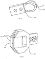
Fig. 5a shows an isometric view of a first guide mating member; and -
Fig. 5b shows an isometric view of a second guide mating member for receiving the first guide mating member. -
Fig. 1 shows a conventional sealing jaw assembly producing irregular tetrahedral packages, whereasFig. 2 shows an isometric view of a sequence of irregular tetrahedral packages produced by the sealing jaw assembly ofFig. 1 . The pairs of sealing jaws (22a-b, 24a-b) are mounted for reciprocal motion toward and away from one another, as is indicated with arrows on each jaw. The jaws of one pair when moved toward each other act to compress and flatten atube 12 of packaging material so as to adhere opposed interior surfaces of thepackaging material 10 together to achieve aseal jaws 22a-b, 24a-b may e.g. be oriented that they meet and make a seal in planes which are perpendicular to one another, i.e. Y1 is perpendicular to Y2. However, adjacent pairs of jaws may also be oriented such that their respective seal planes are not perpendicular to each other. - In order to achieve the unique irregularity of the tetrahedral shape of the
packages tube 12 so that the sealing axis Y1, Y2 of the transversal sealing achieved by each pair of jaws has the same predetermined angular relationship to the longitudinal axis Z of thetube 12 of packaging material. - Multiple pairs of sealing jaws may be provided in a sealing assembly. For example, the sealing jaw assembly shown in
Fig. 1 could be equipped with additional pairs of sealing jaws whereby a pair of sealing jaws, identical to the pair of sealingjaws 22a-b, is arranged downstream the pair of sealingjaws 24a-b, etc. During a sealing step, every second pair ofjaws 22a-b perform the same movement along the same plane and with the same optional angle. The remaining pair ofjaws 24a-b perform the same movement along the same plane and with the same optional angle, but the direction of movement towards the tube of packaging material is arranged at an angle relative to the reciprocating movement of thejaws 22a-b. This means that the planes of the transversal seals made withjaws 22a-b are angled relative to the planes of the transversal seals made withjaws 24a-b. - In
Fig. 1 , a longitudinal central axis Z of the tube of packaging material has been indicated, which in normal production is vertical. All the transversal seals, made with the pairs of sealing jaws, intersect said longitudinal axis Z. - Each
transversal seal transversal seal tube 12 intoindividual packages - In
Fig. 1 , it may appear that thetube 12 of packaging material is stationary and the jaws 22a.b, 24a-b provide thetransversal sealings jaw 22a-b, 24a-b makes contact with thetube 12 of packaging material at an almost constant position (position along Z), and thetube 12 is then pulled down allowing for anew sealing jaw 22a-b, 24a-b to again make atransversal seal jaws 22a-b, 24a-b on thetube 12 is what feeds theweb 10 of packaging material through the machine. Sometimes, additional feeding rollers are provided further upstream in the filling machine, in order to reduce the tension in the web. - It should be appreciated that
Fig. 1 is just a schematic representation used for illustrative purposes to explain the commonly known functionality of sealingjaws 22a-b, 24a-b for the production of irregular tetrahedral packages, and the present invention is not necessarily limited to any particularly arranged orangled sealing jaws 22a-b, 24a-b. -
Figs. 3a to 3c respectively shows a top view of a sealingjaw assembly 100 for providing transversal seals 6 to atube 12 of packaging material according to an example. The sealingjaw assembly 100, as explained in the following, could thus form one pair of sealingjaws 22a-b, 24a-b previously described with respect toFig. 1 . The sealingjaw assembly 100 comprises at least one pair ofopposing sealing jaws Fig. 1 ) to thetube 12 when the tube passes between the sealingjaws sealing jaws first sealing jaw 130 having a firstguide mating member 131 protruding beyond a sealingsurface 132 of thefirst sealing jaw 130. Asecond sealing jaw 140 is provided with a secondguide mating member 141 for receiving the firstguide mating member 131 when thefirst sealing jaw 130 and thesecond sealing jaw 140 move towards each other, as shown inFigs. 3b and 3c , thereby properly aligning the at least one pair of opposing sealingjaws - As shown in
Figs 3b and 3c the secondguide mating member 141 receives the firstguide mating member 131 before thefirst sealing jaw 130 andsecond sealing jaw 140 attains their operative position for providing a transversal seal, i.e. their sealing end position, as shown inFig. 3c . In this way the first sealing jaw 130and thesecond sealing jaw 140 may be properly aligned in relation to each other. - As shown in
Figs. 3b and 3c thetube 12 is pressed together when the two sealingjaws - Proper alignment is of particular importance in situations where the sealing
jaws jaw jaws jaws - The second
guide mating member 141 may comprise anopening 142 for receiving aprotrusion 133 of the firstguide mating member 131. - With reference to
Figs. 5a and 5b in view ofFigs. 3a to 3c , the secondguide mating member 141 may comprise at least onechamfered edge 143 arranged adjacent theopening 142 for guiding theprotrusion 133 into theopening 142 when thefirst sealing jaw 130 andsecond sealing jaw 140 move towards each other. - As shown in
Fig. 5a theprotrusion 133 may comprise arounded end portion 134. Theopening 142 may have shape for providing a tight sliding fit when theprotrusion 133 is received by the opening before the sealingjaws Fig. 3c . This means that theopening 142 does not necessarily has an exact corresponding rounded portion to that of theprotrusion 133 since the firstguide mating member 131 may approach the second guide mating member along an arc path in a plane being parallel to the longitudinal extension L of thetube 12. Hence, the guidingmembers jaws - As shown in
Figs. 5a and 5b the respectiveguide mating member jaw guide mating member jaw - Either the
first sealing jaw 130 orsecond sealing jaw 140 may comprise an induction heating circuit for providing the transversal seal 6 to the tube. Moreover, either thefirst sealing jaw 130 orsecond sealing jaw 140 may comprise a knife for cutting the tube along the transversal seal 6. -
Fig. 4 shows a side view of two sealingjaws Fig. 3c . InFig. 4 , it is noted that the sealing jaws in the sealing position are tilted against the horizontal axis H, which means that their direction of width is angled at an angle α against the horizontal plane. The longitudinal extension of thetube 12 is indicated by the dotted line L inFig. 4 . Even if the sealingjaws guide mating member 131, and secondguide mating member 141 are arranged such as to mate in a plane parallel to the plane comprising the arc path along which the two sealingjaws tube 12.Fig. 4 shows such a configuration. - As shown in
Figs 3a to 3c , theopening 142 may have two parallel arranged opposing interior side walls extending parallel to the plane comprising the arc path along which the two sealingjaws protrusion 133 may have two parallel opposing outer surfaces also arranged parallel to the plane comprising the arc path along which the two sealingjaws protrusion 133, thereby preventing the firstguide mating member 131, and the secondguide mating member 132 to move in a direction perpendicular to the plane comprising the arc path along which the two sealingjaws jaws guide mating member 132 provides for an alignment between the two sealingjaws jaws - This alignment reduces the overall wear of the system, and drastically reduces the risk of damage to the knife(s), induction heating system, and other components associated with the provision of the transversal seal.
- As mentioned above, the guide mating member solution is particularly advantageous for sealing jaw assemblies, being tilted at an angle towards the horizontal or a plane being perpendicular to a longitudinal axis of the tube when arranged in their operative position for providing a transversal seal, however it could also be used for sealing jaws arranged parallel to the horizontal.
- Accordingly, each sealing
jaw tube 12 when in the mated end sealing position operative for providing a transversal seal. The angle may be between 15-30°, or preferably between 20-25°. - The respective arc path along which the
first sealing jaw 130 andsecond sealing jaw 140 will move will preferably be arranged in a common plane regardless of whether the sealingjaws - A method for providing a transversal seal to a
tube 12 of packaging material may comprise the following: providing a first pair of opposing sealingjaws first sealing jaw 130 thereof having a firstguide mating member 131 protruding from a sealingsurface 132 of thefirst sealing jaw 130, and asecond sealing jaw 140 thereof having a secondguide mating member 141 for receiving the firstguide mating member 131 when thefirst sealing jaw 130 and thesecond sealing jaw 140 move towards each other, thereby properly aligning the at least one pair of opposing sealingjaws tube 12 when the tube passes between the sealingjaws - Although the drawings have been shown in relation to a single opposing pair of sealing
jaws
Claims (9)
- A sealing jaw assembly for providing transversal seals to a tube of packaging material, said sealing jaw assembly comprising
at least one pair of opposing sealing jaws being movable relative each other to provide a transversal seal to the tube when the tube is arranged between the sealing jaws,
wherein the at least one pair of opposing sealing jaws comprisesa first sealing jaw having a first guide mating member having a part protruding from a sealing surface of the first sealing jaw, anda second sealing jaw having a second guide mating member for receiving the first guide mating member when the first sealing jaw and the second sealing jaw move towards each other and thereby aligning the at least one pair of opposing sealing jaws. - The sealing jaw assembly according to claim 1, wherein the second guide mating member comprises an opening for receiving a protrusion of the first guide mating member.
- The sealing jaw assembly according to claim 2, wherein the second guide mating member comprises at least one chamfered edge arranged adjacent the opening for guiding the protrusion into opening when the first sealing jaw and second sealing jaw move towards each other.
- The sealing jaw assembly according to claims 2 or 3, wherein the protrusion comprises a rounded end portion.
- The sealing jaw assembly according to any one of the previous claims, wherein either the first sealing jaw or second sealing jaw comprises an induction heating circuit for providing the transversal seal to the tube.
- The sealing jaw assembly according to any one of the previous claims, wherein either the first sealing jaw or second sealing jaw comprises a knife for cutting the tube along the transversal seal.
- The sealing jaw assembly according to any of the previous claims, wherein the first sealing jaw and the second sealing jaw are arranged to move along a respective arc path, the arc paths being comprised in a common plane.
- The sealing jaw assembly according to any one of the previous claims, wherein the sealing jaws when arranged in their operative position for providing a transversal seal are tilted relative a plane being perpendicular to a longitudinal axis of tube.
- A method for providing transversal seals to a tube of packaging material, comprising
providing a first pair of opposing sealing jaws being movable relative each other upon activation, whereina first sealing jaw thereof having a first guide mating member having a part protruding from a sealing surface of the first sealing jaw, anda second sealing jaw thereof having a second guide mating member for receiving the first guide mating member when the first sealing jaw and the second sealing jaw move towards each other, thereby properly aligning the at least one pair of opposing sealing jaws, andactivating said first pairs of sealing jaws such as to provide a transversal seal to the tube when the tube is arranged between the sealing jaws.
Applications Claiming Priority (1)
| Application Number | Priority Date | Filing Date | Title |
|---|---|---|---|
| EP16205648 | 2016-12-21 |
Publications (2)
| Publication Number | Publication Date |
|---|---|
| EP3339197A1 true EP3339197A1 (en) | 2018-06-27 |
| EP3339197B1 EP3339197B1 (en) | 2020-11-04 |
Family
ID=57583045
Family Applications (1)
| Application Number | Title | Priority Date | Filing Date |
|---|---|---|---|
| EP17205241.7A Active EP3339197B1 (en) | 2016-12-21 | 2017-12-04 | A method for providing transversal seals to a tube of packaging material, and a sealing jaw assembly |
Country Status (2)
| Country | Link |
|---|---|
| EP (1) | EP3339197B1 (en) |
| CN (2) | CN108216715A (en) |
Families Citing this family (1)
| Publication number | Priority date | Publication date | Assignee | Title |
|---|---|---|---|---|
| CN108216715A (en) * | 2016-12-21 | 2018-06-29 | 利乐拉瓦尔集团及财务有限公司 | The method of transverse sealing and sealing clip assembly are provided to packaging material tube |
Citations (6)
| Publication number | Priority date | Publication date | Assignee | Title |
|---|---|---|---|---|
| US2966021A (en) * | 1955-12-20 | 1960-12-27 | Liqua Pak Inc | Apparatus for forming, filling, sealing and severing containers |
| US4637199A (en) * | 1985-01-30 | 1987-01-20 | International Paper Company | Induction sealing of paperboard |
| EP0887263A1 (en) * | 1997-06-27 | 1998-12-30 | Tetra Laval Holdings & Finance SA | Packaging unit for continuously producing sealed packages, containing pourable food products, from a tube of packaging material |
| WO2000006350A1 (en) * | 1998-07-30 | 2000-02-10 | Unilever Plc | Rotary cutting and/or sealing mechanisms |
| EP1785355A1 (en) * | 2005-11-09 | 2007-05-16 | Tetra Laval Holdings & Finance SA | Packaging unit for continuously producing sealed packages of pourable food products from a tube of packaging material |
| WO2011039710A1 (en) * | 2009-09-30 | 2011-04-07 | Gianluigi Rossi | Automatic packaging machine |
Family Cites Families (4)
| Publication number | Priority date | Publication date | Assignee | Title |
|---|---|---|---|---|
| GB648017A (en) * | 1946-12-04 | 1950-12-28 | Alfonso Mario Donofrio | Improvements in or relating to packaging equipment |
| CN2617686Y (en) * | 2003-05-27 | 2004-05-26 | 张家港市德顺机械有限责任公司 | Replaceable air adjustable packer |
| JP6293863B2 (en) * | 2013-03-28 | 2018-03-14 | テトラ ラバル ホールディングス アンド ファイナンス エス エイ | Package manufacturing method, package material web, package, and filling machine |
| CN108216715A (en) * | 2016-12-21 | 2018-06-29 | 利乐拉瓦尔集团及财务有限公司 | The method of transverse sealing and sealing clip assembly are provided to packaging material tube |
-
2017
- 2017-11-30 CN CN201711235456.6A patent/CN108216715A/en active Pending
- 2017-11-30 CN CN201721637784.4U patent/CN208576755U/en active Active
- 2017-12-04 EP EP17205241.7A patent/EP3339197B1/en active Active
Patent Citations (6)
| Publication number | Priority date | Publication date | Assignee | Title |
|---|---|---|---|---|
| US2966021A (en) * | 1955-12-20 | 1960-12-27 | Liqua Pak Inc | Apparatus for forming, filling, sealing and severing containers |
| US4637199A (en) * | 1985-01-30 | 1987-01-20 | International Paper Company | Induction sealing of paperboard |
| EP0887263A1 (en) * | 1997-06-27 | 1998-12-30 | Tetra Laval Holdings & Finance SA | Packaging unit for continuously producing sealed packages, containing pourable food products, from a tube of packaging material |
| WO2000006350A1 (en) * | 1998-07-30 | 2000-02-10 | Unilever Plc | Rotary cutting and/or sealing mechanisms |
| EP1785355A1 (en) * | 2005-11-09 | 2007-05-16 | Tetra Laval Holdings & Finance SA | Packaging unit for continuously producing sealed packages of pourable food products from a tube of packaging material |
| WO2011039710A1 (en) * | 2009-09-30 | 2011-04-07 | Gianluigi Rossi | Automatic packaging machine |
Also Published As
| Publication number | Publication date |
|---|---|
| CN108216715A (en) | 2018-06-29 |
| CN208576755U (en) | 2019-03-05 |
| EP3339197B1 (en) | 2020-11-04 |
Similar Documents
| Publication | Publication Date | Title |
|---|---|---|
| EP1241098B1 (en) | Ultrasonic transverse sealing device and method for sealing walls of a packaging material filled with a pourable food product | |
| US10112273B2 (en) | Apparatus for taking out flattened tube fins | |
| KR101923407B1 (en) | My waiting | |
| EP3339197B1 (en) | A method for providing transversal seals to a tube of packaging material, and a sealing jaw assembly | |
| JP6588786B2 (en) | Long material bending method and bent product | |
| WO2019163496A1 (en) | Bag manufacturing machine and method for manufacturing plastic bag | |
| US9701507B2 (en) | Method and device for the production of a number of coiled foil rolls | |
| JP2017205966A (en) | Bag making machine | |
| EP3347188B1 (en) | A pressure jaw assembly and a sealing jaw arrangement | |
| US9873534B2 (en) | Tooling for ultrasonic tube sealer for sealing an end portion of a tube to have a rounded configuration | |
| EP3339003B1 (en) | A method for providing transversal seals to a tube of packaging material, and a sealing jaw assembly | |
| US10689142B2 (en) | Apparatus to form edges in a package made of flexible material | |
| CN109070484B (en) | Assembly for producing sealed packaging units | |
| CN107708944A (en) | Dovetail strapping cutter in strapping sealing maching | |
| US20240042643A1 (en) | Tool clamping assembly and assembly | |
| CN101304922B (en) | Packaging unit for continuously producing sealed packages of pourable food products from a tube of packaging material | |
| EP3013163B2 (en) | Device for welding a zip seal in a tobacco pouch | |
| JP4339036B2 (en) | Filling and packaging apparatus and method for producing filled package | |
| JP5954832B2 (en) | Cloth processing equipment | |
| JP6329098B2 (en) | Bag filling and packaging method and apparatus using double bags | |
| EP3339220A2 (en) | Package positioning device, system and method for providing even distances between packages | |
| FR3090589B1 (en) | Method and machine for separating sections for forming flexible bags | |
| CN121038945A (en) | Ultrasonic sealing system and its anvil | |
| JP6074451B2 (en) | Film interlocking mechanism and packaging machine | |
| EP3566958A1 (en) | Folding unit and packaging assembly comprising a folding unit |
Legal Events
| Date | Code | Title | Description |
|---|---|---|---|
| PUAI | Public reference made under article 153(3) epc to a published international application that has entered the european phase |
Free format text: ORIGINAL CODE: 0009012 |
|
| STAA | Information on the status of an ep patent application or granted ep patent |
Free format text: STATUS: THE APPLICATION HAS BEEN PUBLISHED |
|
| AK | Designated contracting states |
Kind code of ref document: A1 Designated state(s): AL AT BE BG CH CY CZ DE DK EE ES FI FR GB GR HR HU IE IS IT LI LT LU LV MC MK MT NL NO PL PT RO RS SE SI SK SM TR |
|
| AX | Request for extension of the european patent |
Extension state: BA ME |
|
| STAA | Information on the status of an ep patent application or granted ep patent |
Free format text: STATUS: REQUEST FOR EXAMINATION WAS MADE |
|
| 17P | Request for examination filed |
Effective date: 20190102 |
|
| RBV | Designated contracting states (corrected) |
Designated state(s): AL AT BE BG CH CY CZ DE DK EE ES FI FR GB GR HR HU IE IS IT LI LT LU LV MC MK MT NL NO PL PT RO RS SE SI SK SM TR |
|
| GRAP | Despatch of communication of intention to grant a patent |
Free format text: ORIGINAL CODE: EPIDOSNIGR1 |
|
| STAA | Information on the status of an ep patent application or granted ep patent |
Free format text: STATUS: GRANT OF PATENT IS INTENDED |
|
| RIC1 | Information provided on ipc code assigned before grant |
Ipc: B29C 65/36 20060101ALN20200525BHEP Ipc: B65B 51/22 20060101ALN20200525BHEP Ipc: B29C 65/74 20060101ALN20200525BHEP Ipc: B65B 51/30 20060101AFI20200525BHEP |
|
| INTG | Intention to grant announced |
Effective date: 20200619 |
|
| GRAS | Grant fee paid |
Free format text: ORIGINAL CODE: EPIDOSNIGR3 |
|
| GRAA | (expected) grant |
Free format text: ORIGINAL CODE: 0009210 |
|
| STAA | Information on the status of an ep patent application or granted ep patent |
Free format text: STATUS: THE PATENT HAS BEEN GRANTED |
|
| AK | Designated contracting states |
Kind code of ref document: B1 Designated state(s): AL AT BE BG CH CY CZ DE DK EE ES FI FR GB GR HR HU IE IS IT LI LT LU LV MC MK MT NL NO PL PT RO RS SE SI SK SM TR |
|
| REG | Reference to a national code |
Ref country code: GB Ref legal event code: FG4D |
|
| REG | Reference to a national code |
Ref country code: CH Ref legal event code: EP |
|
| REG | Reference to a national code |
Ref country code: AT Ref legal event code: REF Ref document number: 1330538 Country of ref document: AT Kind code of ref document: T Effective date: 20201115 |
|
| REG | Reference to a national code |
Ref country code: IE Ref legal event code: FG4D |
|
| REG | Reference to a national code |
Ref country code: DE Ref legal event code: R096 Ref document number: 602017026743 Country of ref document: DE |
|
| REG | Reference to a national code |
Ref country code: NL Ref legal event code: MP Effective date: 20201104 |
|
| REG | Reference to a national code |
Ref country code: AT Ref legal event code: MK05 Ref document number: 1330538 Country of ref document: AT Kind code of ref document: T Effective date: 20201104 |
|
| PG25 | Lapsed in a contracting state [announced via postgrant information from national office to epo] |
Ref country code: RS Free format text: LAPSE BECAUSE OF FAILURE TO SUBMIT A TRANSLATION OF THE DESCRIPTION OR TO PAY THE FEE WITHIN THE PRESCRIBED TIME-LIMIT Effective date: 20201104 Ref country code: PT Free format text: LAPSE BECAUSE OF FAILURE TO SUBMIT A TRANSLATION OF THE DESCRIPTION OR TO PAY THE FEE WITHIN THE PRESCRIBED TIME-LIMIT Effective date: 20210304 Ref country code: NO Free format text: LAPSE BECAUSE OF FAILURE TO SUBMIT A TRANSLATION OF THE DESCRIPTION OR TO PAY THE FEE WITHIN THE PRESCRIBED TIME-LIMIT Effective date: 20210204 Ref country code: GR Free format text: LAPSE BECAUSE OF FAILURE TO SUBMIT A TRANSLATION OF THE DESCRIPTION OR TO PAY THE FEE WITHIN THE PRESCRIBED TIME-LIMIT Effective date: 20210205 Ref country code: FI Free format text: LAPSE BECAUSE OF FAILURE TO SUBMIT A TRANSLATION OF THE DESCRIPTION OR TO PAY THE FEE WITHIN THE PRESCRIBED TIME-LIMIT Effective date: 20201104 |
|
| PG25 | Lapsed in a contracting state [announced via postgrant information from national office to epo] |
Ref country code: SE Free format text: LAPSE BECAUSE OF FAILURE TO SUBMIT A TRANSLATION OF THE DESCRIPTION OR TO PAY THE FEE WITHIN THE PRESCRIBED TIME-LIMIT Effective date: 20201104 Ref country code: BG Free format text: LAPSE BECAUSE OF FAILURE TO SUBMIT A TRANSLATION OF THE DESCRIPTION OR TO PAY THE FEE WITHIN THE PRESCRIBED TIME-LIMIT Effective date: 20210204 Ref country code: IS Free format text: LAPSE BECAUSE OF FAILURE TO SUBMIT A TRANSLATION OF THE DESCRIPTION OR TO PAY THE FEE WITHIN THE PRESCRIBED TIME-LIMIT Effective date: 20210304 Ref country code: LV Free format text: LAPSE BECAUSE OF FAILURE TO SUBMIT A TRANSLATION OF THE DESCRIPTION OR TO PAY THE FEE WITHIN THE PRESCRIBED TIME-LIMIT Effective date: 20201104 Ref country code: PL Free format text: LAPSE BECAUSE OF FAILURE TO SUBMIT A TRANSLATION OF THE DESCRIPTION OR TO PAY THE FEE WITHIN THE PRESCRIBED TIME-LIMIT Effective date: 20201104 Ref country code: AT Free format text: LAPSE BECAUSE OF FAILURE TO SUBMIT A TRANSLATION OF THE DESCRIPTION OR TO PAY THE FEE WITHIN THE PRESCRIBED TIME-LIMIT Effective date: 20201104 Ref country code: ES Free format text: LAPSE BECAUSE OF FAILURE TO SUBMIT A TRANSLATION OF THE DESCRIPTION OR TO PAY THE FEE WITHIN THE PRESCRIBED TIME-LIMIT Effective date: 20201104 |
|
| REG | Reference to a national code |
Ref country code: LT Ref legal event code: MG9D |
|
| PG25 | Lapsed in a contracting state [announced via postgrant information from national office to epo] |
Ref country code: HR Free format text: LAPSE BECAUSE OF FAILURE TO SUBMIT A TRANSLATION OF THE DESCRIPTION OR TO PAY THE FEE WITHIN THE PRESCRIBED TIME-LIMIT Effective date: 20201104 |
|
| PG25 | Lapsed in a contracting state [announced via postgrant information from national office to epo] |
Ref country code: RO Free format text: LAPSE BECAUSE OF FAILURE TO SUBMIT A TRANSLATION OF THE DESCRIPTION OR TO PAY THE FEE WITHIN THE PRESCRIBED TIME-LIMIT Effective date: 20201104 Ref country code: SK Free format text: LAPSE BECAUSE OF FAILURE TO SUBMIT A TRANSLATION OF THE DESCRIPTION OR TO PAY THE FEE WITHIN THE PRESCRIBED TIME-LIMIT Effective date: 20201104 Ref country code: SM Free format text: LAPSE BECAUSE OF FAILURE TO SUBMIT A TRANSLATION OF THE DESCRIPTION OR TO PAY THE FEE WITHIN THE PRESCRIBED TIME-LIMIT Effective date: 20201104 Ref country code: CZ Free format text: LAPSE BECAUSE OF FAILURE TO SUBMIT A TRANSLATION OF THE DESCRIPTION OR TO PAY THE FEE WITHIN THE PRESCRIBED TIME-LIMIT Effective date: 20201104 Ref country code: EE Free format text: LAPSE BECAUSE OF FAILURE TO SUBMIT A TRANSLATION OF THE DESCRIPTION OR TO PAY THE FEE WITHIN THE PRESCRIBED TIME-LIMIT Effective date: 20201104 Ref country code: LT Free format text: LAPSE BECAUSE OF FAILURE TO SUBMIT A TRANSLATION OF THE DESCRIPTION OR TO PAY THE FEE WITHIN THE PRESCRIBED TIME-LIMIT Effective date: 20201104 |
|
| REG | Reference to a national code |
Ref country code: CH Ref legal event code: PL |
|
| REG | Reference to a national code |
Ref country code: DE Ref legal event code: R097 Ref document number: 602017026743 Country of ref document: DE |
|
| PG25 | Lapsed in a contracting state [announced via postgrant information from national office to epo] |
Ref country code: DK Free format text: LAPSE BECAUSE OF FAILURE TO SUBMIT A TRANSLATION OF THE DESCRIPTION OR TO PAY THE FEE WITHIN THE PRESCRIBED TIME-LIMIT Effective date: 20201104 Ref country code: MC Free format text: LAPSE BECAUSE OF FAILURE TO SUBMIT A TRANSLATION OF THE DESCRIPTION OR TO PAY THE FEE WITHIN THE PRESCRIBED TIME-LIMIT Effective date: 20201104 |
|
| REG | Reference to a national code |
Ref country code: BE Ref legal event code: MM Effective date: 20201231 |
|
| PLBE | No opposition filed within time limit |
Free format text: ORIGINAL CODE: 0009261 |
|
| STAA | Information on the status of an ep patent application or granted ep patent |
Free format text: STATUS: NO OPPOSITION FILED WITHIN TIME LIMIT |
|
| 26N | No opposition filed |
Effective date: 20210805 |
|
| PG25 | Lapsed in a contracting state [announced via postgrant information from national office to epo] |
Ref country code: LU Free format text: LAPSE BECAUSE OF NON-PAYMENT OF DUE FEES Effective date: 20201204 Ref country code: AL Free format text: LAPSE BECAUSE OF FAILURE TO SUBMIT A TRANSLATION OF THE DESCRIPTION OR TO PAY THE FEE WITHIN THE PRESCRIBED TIME-LIMIT Effective date: 20201104 Ref country code: FR Free format text: LAPSE BECAUSE OF NON-PAYMENT OF DUE FEES Effective date: 20210104 Ref country code: IE Free format text: LAPSE BECAUSE OF NON-PAYMENT OF DUE FEES Effective date: 20201204 Ref country code: NL Free format text: LAPSE BECAUSE OF FAILURE TO SUBMIT A TRANSLATION OF THE DESCRIPTION OR TO PAY THE FEE WITHIN THE PRESCRIBED TIME-LIMIT Effective date: 20201104 |
|
| PG25 | Lapsed in a contracting state [announced via postgrant information from national office to epo] |
Ref country code: LI Free format text: LAPSE BECAUSE OF NON-PAYMENT OF DUE FEES Effective date: 20201231 Ref country code: SI Free format text: LAPSE BECAUSE OF FAILURE TO SUBMIT A TRANSLATION OF THE DESCRIPTION OR TO PAY THE FEE WITHIN THE PRESCRIBED TIME-LIMIT Effective date: 20201104 Ref country code: CH Free format text: LAPSE BECAUSE OF NON-PAYMENT OF DUE FEES Effective date: 20201231 |
|
| PG25 | Lapsed in a contracting state [announced via postgrant information from national office to epo] |
Ref country code: IS Free format text: LAPSE BECAUSE OF FAILURE TO SUBMIT A TRANSLATION OF THE DESCRIPTION OR TO PAY THE FEE WITHIN THE PRESCRIBED TIME-LIMIT Effective date: 20210304 Ref country code: TR Free format text: LAPSE BECAUSE OF FAILURE TO SUBMIT A TRANSLATION OF THE DESCRIPTION OR TO PAY THE FEE WITHIN THE PRESCRIBED TIME-LIMIT Effective date: 20201104 Ref country code: MT Free format text: LAPSE BECAUSE OF FAILURE TO SUBMIT A TRANSLATION OF THE DESCRIPTION OR TO PAY THE FEE WITHIN THE PRESCRIBED TIME-LIMIT Effective date: 20201104 Ref country code: CY Free format text: LAPSE BECAUSE OF FAILURE TO SUBMIT A TRANSLATION OF THE DESCRIPTION OR TO PAY THE FEE WITHIN THE PRESCRIBED TIME-LIMIT Effective date: 20201104 |
|
| PG25 | Lapsed in a contracting state [announced via postgrant information from national office to epo] |
Ref country code: MK Free format text: LAPSE BECAUSE OF FAILURE TO SUBMIT A TRANSLATION OF THE DESCRIPTION OR TO PAY THE FEE WITHIN THE PRESCRIBED TIME-LIMIT Effective date: 20201104 |
|
| PG25 | Lapsed in a contracting state [announced via postgrant information from national office to epo] |
Ref country code: BE Free format text: LAPSE BECAUSE OF NON-PAYMENT OF DUE FEES Effective date: 20201231 |
|
| GBPC | Gb: european patent ceased through non-payment of renewal fee |
Effective date: 20211204 |
|
| PG25 | Lapsed in a contracting state [announced via postgrant information from national office to epo] |
Ref country code: GB Free format text: LAPSE BECAUSE OF NON-PAYMENT OF DUE FEES Effective date: 20211204 |
|
| P01 | Opt-out of the competence of the unified patent court (upc) registered |
Effective date: 20230426 |
|
| PGFP | Annual fee paid to national office [announced via postgrant information from national office to epo] |
Ref country code: IT Payment date: 20251218 Year of fee payment: 9 |
|
| PGFP | Annual fee paid to national office [announced via postgrant information from national office to epo] |
Ref country code: DE Payment date: 20251229 Year of fee payment: 9 |