EP3339155A1 - Control device for a bicycle - Google Patents
Control device for a bicycle Download PDFInfo
- Publication number
- EP3339155A1 EP3339155A1 EP17207857.8A EP17207857A EP3339155A1 EP 3339155 A1 EP3339155 A1 EP 3339155A1 EP 17207857 A EP17207857 A EP 17207857A EP 3339155 A1 EP3339155 A1 EP 3339155A1
- Authority
- EP
- European Patent Office
- Prior art keywords
- pin
- brake lever
- control device
- abutment portion
- release position
- Prior art date
- Legal status (The legal status is an assumption and is not a legal conclusion. Google has not performed a legal analysis and makes no representation as to the accuracy of the status listed.)
- Granted
Links
Images






Classifications
-
- B—PERFORMING OPERATIONS; TRANSPORTING
- B62—LAND VEHICLES FOR TRAVELLING OTHERWISE THAN ON RAILS
- B62L—BRAKES SPECIALLY ADAPTED FOR CYCLES
- B62L3/00—Brake-actuating mechanisms; Arrangements thereof
- B62L3/02—Brake-actuating mechanisms; Arrangements thereof for control by a hand lever
-
- B—PERFORMING OPERATIONS; TRANSPORTING
- B62—LAND VEHICLES FOR TRAVELLING OTHERWISE THAN ON RAILS
- B62M—RIDER PROPULSION OF WHEELED VEHICLES OR SLEDGES; POWERED PROPULSION OF SLEDGES OR SINGLE-TRACK CYCLES; TRANSMISSIONS SPECIALLY ADAPTED FOR SUCH VEHICLES
- B62M25/00—Actuators for gearing speed-change mechanisms specially adapted for cycles
- B62M25/02—Actuators for gearing speed-change mechanisms specially adapted for cycles with mechanical transmitting systems, e.g. cables, levers
- B62M25/04—Actuators for gearing speed-change mechanisms specially adapted for cycles with mechanical transmitting systems, e.g. cables, levers hand actuated
Definitions
- the present invention relates to a control device for a bicycle.
- the invention relates to a control device used for actuating a brake for the front or rear wheel of the bicycle and, possibly, at least one other bicycle equipment, such as for example a (front or rear) derailleur, a servo-assisted gearshift or a cycle computer.
- a control device used for actuating a brake for the front or rear wheel of the bicycle and, possibly, at least one other bicycle equipment, such as for example a (front or rear) derailleur, a servo-assisted gearshift or a cycle computer.
- the control device of the present invention is preferably intended to be used in a racing bicycle, namely a bicycle having a handlebar with opposite curved free end portions.
- the control device of the invention can also be gripped or used by the cyclist to ride the bicycle, as an alternative to the classic handgrip provided on the curved free end portions of the handlebar.
- the spatial terms in particular the terms: front, rear, side, upper, lower, vertical and horizontal, are used with reference to the mounted condition of the control device on the handlebar of the bicycle.
- the terms “inner” and “outer” identify, on the other hand, with reference to the handlebar in neutral position, the area towards the center of the handlebar with respect to an intermediate reference plane that crosses the control device substantially vertically.
- Known control devices typically comprise a body intended to be fixed to the curved free end portions of the handlebar through conventional connection elements, for example a clip.
- the body is typically defined by an outer side wall, an inner side wall substantially parallel to the outer side wall, an upper transverse wall that connects together the outer side wall and the inner side wall and a lower transverse wall opposite to the upper wall. All of the walls are typically covered with an outer sheath.
- the body is mounted on the handlebar of the bicycle so as to project at the front of the latter and is configured so as to facilitate the cyclist's grip in certain race situations. It thus has an ergonomic shape, typically comprising an upward protuberance in the front area thereof.
- a brake lever and, typically, one or more control members (levers and/or buttons) for actuating a derailleur or a servo-assisted gearshift and possibly also for controlling a cycle computer are associated with the body.
- some control devices of the prior art comprise adjustment means of the release position of the brake lever.
- release position indicates the position taken up by the brake lever when the cyclist releases the brake lever, namely when the cyclist does not actuate the brake of the bicycle.
- any reference to the position taken up by the brake lever with respect to the handlebar should be taken as referring to the position taken up by the part of the brake lever arranged below the rotation axis and intended to be actuated by the fingers of the cyclist during braking.
- the aforementioned adjustment means of the release position of the brake lever make it possible to modify the release position by bringing the brake lever towards the handlebar, so as to make it easier for example for cyclists with small hands.
- the brake lever may be too far from the handlebar to be able to be easily actuated by such a cyclist when he/she rides the bicycle gripping the handlebar at the opposite curved end portions thereof.
- US 8261888 describes a control device for a bicycle in which a detachment position of the brake lever is provided, namely a position of complete loss of tension for the brake cable of the bicycle.
- the detachment position makes it possible to release the cable and to open the brake pads, so as to be able to remove the wheel faster.
- the technical problem at the basis of the present invention is that of providing a control device for a bicycle that allows the adjustment of the release position of the brake lever through a solution alternative to those of the prior art.
- the invention therefore relates to a control device for a bicycle, comprising:
- the adjustment of the release position of the brake lever is obtained by selectively positioning the aforementioned pin in at least two distinct stop positions upon sliding along the aforementioned sliding direction, and the consequent abutment of the pin on at least two distinct abutment portions defined in the aforementioned body.
- one of said pin and said coupling element comprises at least two circumferential grooves and the other of said pin and said coupling element comprises a circumferential tooth configured to selectively couple with one of said at least two circumferential grooves.
- said pin comprises said at least two circumferential grooves and said coupling element comprises said circumferential tooth.
- said coupling element comprises said at least two circumferential grooves and said pin comprises said circumferential tooth.
- said circumferential tooth is formed on a bush fixedly associated with said brake lever and said at least two circumferential grooves are formed on said pin, said pin being slidable in said bush along said sliding direction.
- said circumferential tooth is formed on said pin and said at least two circumferential grooves are formed on said bush.
- said first abutment portion and said at least one second abutment portion have different depths with respect to an outer surface of said body facing towards said brake lever.
- the brake lever is positioned with respect to the body at different angles about the predetermined rotation axis, thus defining the aforementioned different release positions of the brake lever.
- said first abutment portion and said at least one second abutment portion are arranged side by side.
- said first abutment portion and said at least one second abutment portion are arranged on the same side with respect to said brake lever.
- said first abutment portion and said at least one second abutment portion are arranged on opposite sides with respect to said brake lever.
- said body comprises a third abutment portion defining a detachment position of said brake lever, said adjustment means being configured to selectively select said detachment position as an alternative to said first release position and at least one second release position.
- the same adjustment means provided to selectively select the different release positions of the brake lever are also used to select the detachment position of the brake lever.
- said third abutment portion is arranged on the opposite side to at least one of said first abutment portion and said at least one second abutment portion with respect to said brake lever.
- said first abutment portion and said at least one second abutment portion are arranged on the same side with respect to said brake lever and said third abutment portion is arranged on the opposite side to said first abutment portion and at least one second abutment portion with respect to said brake lever.
- said first abutment portion and said at least one second abutment portion are arranged on opposite sides with respect to said brake lever and said third abutment portion is arranged on the same side as one of said first abutment portion and said at least one second abutment portion with respect to said brake lever.
- said pin is slidable along said sliding direction until a third stop position is reached at which said pin goes into abutment on said third abutment portion.
- said coupling element is configured to selectively stop said pin in said third stop position.
- one of said pin and said coupling element comprises a third circumferential groove and the other of said pin and said coupling element comprises said circumferential tooth, wherein said third circumferential groove is configured to couple with said circumferential tooth when said pin reaches said third stop position.
- said circumferential tooth is formed on said coupling element and said third circumferential groove is formed on said pin in a position adjacent to said at least two circumferential grooves.
- said pin comprises opposite free end portions that project with respect to said brake lever when said pin is in said first stop position and at least one second stop position.
- At least one of said free end portions projects with respect to said brake lever when said pin is in said third stop position.
- Such a provision allows the cyclist to easily select the desired release position or detachment position by pushing the pin along the sliding direction directly with a finger.
- FIGS 1a-5b show a first preferred embodiment of a control device for a bicycle in accordance with the present invention, wholly indicated with 10.
- Such a control device 10 comprises a body 20 configured to be mounted on the handlebar (not shown) of a racing bicycle at one of the opposite curved free end portions of the handlebar itself.
- the control device 10 is, in particular, a right control device, namely a control device intended to be associated with the handlebar of the bicycle at the curved free end portion of the handlebar that, viewing the handlebar in its neutral position and from a viewpoint like that of the cyclist while riding, is to the right of the cyclist.
- a right control device namely a control device intended to be associated with the handlebar of the bicycle at the curved free end portion of the handlebar that, viewing the handlebar in its neutral position and from a viewpoint like that of the cyclist while riding, is to the right of the cyclist.
- the body 20 is configured to be fixed, at a rear wall 22 thereof, to a curved free end portion of the handlebar, so as to project at the front from said handlebar to be grippable by the cyclist in certain race conditions, like for example in climbs.
- connection means like for example a strap.
- the body 20 is defined, in addition to by the rear wall 22, by an outer side wall 26a ( figure 2 ), an inner side wall 26b ( figures 1a-1c and 2 ) arranged on the opposite side to the outer side wall 26a with respect to an intermediate reference plane P ( figure 3a ) that passes vertically through the body 20, an upper transverse wall 28a ( figures 1a-1c ) that connects together the outer and inner side walls 26a, 26b and a lower transverse wall 28b ( figures 1a-1c ) opposite to the upper transverse wall 28a.
- intermediate reference plane is used to indicate any substantially vertical plane that passes through the control device 10, not necessarily a plane of symmetry or a mid-plane of the control device 10.
- the outer side wall 26a and the inner side wall 26b of the control device 10 have respective surfaces substantially parallel to the intermediate reference plane P, apart from small concavities and convexities.
- the body 20 is configured so as to make it easier for the cyclist to grip it. It thus has an ergonomic shape, typically comprising, in a front portion 20a thereof, an upward protuberance 24.
- the upper transverse wall 28a of the body 20 thus has a substantially saddle shaped profile, as shown in figures 1a-1c .
- All of the aforementioned walls of the control device 10 are covered with an outer covering sheath.
- a brake lever 30 and a gearshift lever 40 intended to control a derailleur (not shown) of the bicycle in a first gearshifting direction (in particular the rear derailleur) are associated with the body 20.
- the brake lever 30 is hinged to the body 20 at the front portion 20a of the body 20 in a totally conventional manner.
- the brake lever 30 is rotatable about a predetermined rotation axis X.
- the gearshift lever 40 is arranged behind the brake lever 30 and is articulated to the body 20 in a totally conventional manner.
- the control device 10 can comprise a further gearshift lever (not shown) for actuating the derailleur in a gearshifting direction opposite to that in which the derailleur is actuated by acting on the gearshift lever 40.
- the further gearshift lever is articulated to the body 20 in a totally conventional manner.
- the gearshift lever 40 and the further gearshift lever act on a derailleur control device 42, which is of the mechanical type in the case illustrated, arranged inside the body 20.
- the body 20 comprises a first abutment portion 50 defining a first release position of the brake lever 30 and a second abutment portion 52 defining a second release position of the brake lever 30.
- the first abutment portion 50 and the second abutment portion 52 have different depths with respect to an outer surface 21 of the body 20 facing towards the brake lever 30 ( figure 2 ).
- the first abutment portion 50 has a depth greater than that of the second abutment portion 52.
- the first abutment portion 50 and the second abutment portion 52 are arranged side-by-side and on the same side with respect to the brake lever 30.
- the abutment portions 50 and 52 are formed on the inner side wall 26b of the body 20.
- the first release position is shown in figures 1a , 3a, 3b and 3c and is indicated hereinafter as "standard release position".
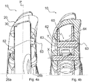
- the second release position on the other hand, is shown in figures 1b , 4a and 4b and is indicated hereinafter as "release position for small hands".
- the standard release position is suitable for cyclists with average sized hands, whereas the release position for small hands is suitable for cyclists with smaller than average hands.
- the brake lever 30 is closer to the rear wall 22 of the body 20 (and therefore closer to the handlebar) than in the standard release position, as can be seen by comparing figures 1a and 1b .
- the control device 10 further comprises adjustment means 60 configured to selectively select one of the aforementioned release positions.
- the adjustment means 60 comprise a pin 62 mounted on the brake lever 30 ( figure 3b ).
- the pin 62 is slidable along a sliding direction y, which is substantially parallel to the rotation axis X, between a first stop position ( figures 3a-3c ) and a second stop position ( figures 4a and 4b ).
- the pin 62 goes into abutment on the first abutment portion 50 of the body 20, whereas at the second stop position the pin 62 goes into abutment on the second abutment portion 52 of the body 20.
- the adjustment means 60 also comprise a coupling element 64 for coupling with the pin 62.
- the coupling element 64 is fixedly associated with the brake lever 30 and is configured to selectively stop the pin 62 in the aforementioned first and second stop positions.
- the coupling element 64 is defined by a bush (indicated with 64 in figures 3b , 4b and 5b ).
- the pin 62 can slide along the sliding direction y inside the bush.
- the pin 62 comprises two circumferential grooves 62a arranged side by side with respect to the axis Y of the pin 62, namely along the sliding direction y, and the coupling element 64 comprises a circumferential tooth 64a configured to selectively couple with one of the two circumferential grooves 62a.
- the coupling between the circumferential tooth 64a and the two circumferential grooves 62a is preferably of the snap type.
- the body 20 further comprises a third abutment portion 54 defining a detachment position of the brake lever 30.
- the adjustment means 60 are configured to selectively select the detachment position as an alternative to the aforementioned first and second release position.
- the third abutment portion 54 is arranged on the opposite side to the abutment portions 50 and 52 with respect to the brake lever 30.
- the third abutment portion 54 is formed on the outer side wall 26a of the body 20.
- the third abutment portion 54 has a depth, with respect to the outer surface 21 of the body 20, greater than that of the first abutment portion 50 and of the second abutment portion 52 ( figure 2 ).
- the detachment position is shown in figures 1c , 5a and 5b .
- the pin 62 is slidable along the sliding direction y so as to reach, in addition to the aforementioned first and second stop positions, a third stop position ( figure 5b ), at which the pin 62 goes into abutment on the third abutment portion 54,.
- the coupling element 64 is configured to selectively stop the pin 62 in the aforementioned third stop position as well as in the aforementioned first and second stop positions.
- the pin 62 comprises a third circumferential groove 62b, as shown in figure 3c .
- the third circumferential groove 62b and the two circumferential grooves 62a are arranged side by side with respect to the axis Y of the pin 62, namely along the sliding direction y.
- the third circumferential groove 62b is configured to couple with the circumferential tooth 64a of the coupling element 64, thus stopping the pin 62 in the aforementioned third stop position.
- the coupling between the circumferential tooth 64a and the third circumferential groove 62b is also of the snap type.
- the pin 62 comprises opposite free end portions 63 that project with respect to the brake lever 30 when the pin 62 is in the aforementioned first stop position.
- one of the aforementioned free end portions 63 projects laterally with respect to the brake lever 30 when the pin 62 is in the aforementioned second stop position.
- the opposite free end portion 63 of the pin 62 projects laterally with respect to the brake lever 30 when the pin 62 is in the aforementioned third stop position.
- FIGS 6a-11b show a second preferred embodiment of a control device for a bicycle in accordance with the present invention, wholly indicated with 10.
- the second embodiment shown in figures 6a-11b differs from the one shown in figures 1a-5b in that the control device 10 is configured so that the brake lever 30 can also take up a third release position, in addition to the two release positions and the detachment position provided in the first embodiment shown in figures 1a-5b .
- Such a third release position is shown in figures 6c , 10a and 10b and it is indicated hereinafter as "release position for large hands”.
- the first release position is shown in figures 6a , 8a and 8b and is indicated hereinafter as "standard release position". Such a first release position corresponds to the first release position shown in figures 1a , 3a, 3b and 3c .
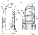
- the second release position is shown in figures 6b , 9a and 9b and is indicated hereinafter as "release position for small hands". Such a second release position corresponds to the second release position shown in figures 1b , 4a and 4b .
- the detachment position is shown in figures 6d , 11a and 11b and corresponds to the detachment position shown in figures 1c , 5a and 5b .
- the release position for large hands is suitable for cyclists with larger than average hands.
- the brake lever 30 is further far from the rear wall 22 of the body 20 (and therefore further far from the handlebar) with respect to the standard release position, as can be seen by comparing figures 6a and 6c .
- the body 20 comprises, in addition to the first abutment portion 50 defining the first release position of the brake lever 30, the second abutment portion 52 defining the second release position of the brake lever 30 and the third abutment portion 54 defining the detachment position of the brake lever 30, also a fourth abutment portion 156 defining the third release position of the brake lever 30.
- the first abutment portion 50, the second abutment portion 52 and the fourth abutment portion 156 have different depths with respect to the outer surface 21 of the body 20 facing towards the brake lever 30 ( figure 7 ).
- the fourth abutment portion 156 has a depth greater than that of the first abutment portion 50, which in turn is greater than that of the second abutment portion 52.
- the fourth abutment portion 156 further has a depth smaller than that of the third abutment portion 54.
- the first abutment portion 50, the second abutment portion 52 and the fourth abutment portion 156 are arranged side by side and on the same side with respect to the brake lever 30.
- the abutment portions 50, 52 and 156 are formed on the inner side wall 26b of the body 20.
- the third abutment portion 54 is arranged on the opposite side to the abutment portions 50, 52 and 156 with respect to the brake lever 30.
- the third abutment portion 54 is formed on the outer side wall 26a of the body 20.
- the adjustment means 60 are configured to selectively select one of the aforementioned three release positions or the detachment position.
- the pin 62 included in the adjustment means 60 is slidable along the sliding direction y along the first stop position ( figures 8a and 8b ), the second stop position ( figures 9a and 9b ), the third stop position ( figures 11a and 11b ) and a fourth stop position ( figures 10a and 10b ).
- the first, second and third stop position are analogous respectively to those of figures 3a-3c , 4a-4b and 5a-5b , at which the pin 62 goes into abutment on the first, second and third abutment portion 50, 52 and 54, respectively.
- the coupling element 64 included in the adjustment means 60 is configured to selectively stop the pin 62, in addition to in the aforementioned first, second and third stop positions, also in the aforementioned fourth stop position.
- the pin 62 comprises a fourth circumferential groove 62c.
- the fourth circumferential groove 62c, the third circumferential groove 62b and the two circumferential grooves 62a are arranged side by side with respect to the axis Y of the pin 62, i.e. along the sliding direction y.
- the fourth circumferential groove 62c is configured to couple with the circumferential tooth 64a of the coupling element 64, thus stopping the pin 62 in the aforementioned fourth stop position.
- the coupling between the circumferential tooth 64a and the fourth circumferential groove 62c is also of the snap type.
- the opposite free end portions 63 of the pin 62 project with respect to the brake lever 30 when the pin 62 is in the aforementioned first and fourth stop position.
- one of the aforementioned free end portions 63 projects laterally with respect to the brake lever 30 when the pin 62 is in the aforementioned second stop position.
- the opposite free end portion 63 of the pin 62 projects laterally with respect to the brake lever 30 when the pin 62 is in the aforementioned third stop position.
- control device 10 of the invention is already clear from what has been described above and is specified as follows.
- the cyclist can pass from the standard release position ( figures 1a , 3a-3c ) to the release position for small hands ( figures 1b , 4a-4b ) by pushing the pin 62 towards the inner side of the control device 10 (namely by pushing the free end portion 63 of the pin 62 projecting from the brake lever 30 at the outer side wall 26a of the control device 10 towards the inner side wall 26b of the control device 10), whereas it can pass from the standard release position ( figures 1a , 3a-3c ) to the detachment position ( figures 1c , 5a-5b ) by pushing the pin 62 towards the outer side of the control device 10 (namely by pushing the free end portion 63 of the pin 62 projecting from the brake lever 30 at the inner side wall 26b of the control device 10 towards the outer side wall 26a of the control device 10).
- the cyclist can pass from the standard release position ( figures 6a , 8a-8b ) to the release position for small hands ( figures 6b , 9a-9b ) by pushing the pin 62 towards the inner side of the control device 10 (namely by pushing the free end portion 63 of the pin 62 projecting from the brake lever 30 at the outer side wall 26a of the control device 10 towards the inner side wall 26b of the control device 10), whereas it can pass from the standard release position ( figures 6a , 8a-8b ) to the release position for large hands ( figures 6c , 10a-10b ) by pushing the pin 62 towards the outer side of the control device 10 (namely by pushing the free end portion 63 of the pin 62 projecting from the brake lever 30 at the inner side wall 26b of the control device 10 towards the outer side wall 26a of the control device 10).
- the position of the aforementioned abutment portions 50, 52, 54, 156 on the body 20 can be different from the one described above.
- one or more of the aforementioned abutment portions 50, 52, 156 can be formed on the body 20 on the same side as the abutment portion 54 with respect to the brake lever 30.
Landscapes
- Engineering & Computer Science (AREA)
- Mechanical Engineering (AREA)
- Steering Devices For Bicycles And Motorcycles (AREA)
- Mechanical Control Devices (AREA)
- Regulating Braking Force (AREA)
Abstract
- a body (20) configured to be associated with a bicycle handlebar;
- a brake lever associated with said body (20) and rotatable about a predetermined rotation axis (X);
wherein said body (20) comprises a first abutment portion (50) defining a first release position of said brake lever and at least one second abutment portion (52) defining at least one second release position of said brake lever;
the control device (10) further comprising adjustment means configured to selectively select one of said first release position and at least one second release position, wherein said adjustment means comprise:
- a pin mounted on said brake lever and slidable along a sliding direction substantially parallel to the predetermined rotation axis (X) between a first stop position at which said pin goes into abutment on said first abutment portion (50) and at least one second stop position at which said pin goes into abutment on said at least one second abutment portion (52);
- a coupling element for coupling with said pin, said coupling element being fixedly associated with said brake lever and configured to selectively stop said pin in said first stop position and in said at least one second stop position.
Description
- The present invention relates to a control device for a bicycle.
- In particular, the invention relates to a control device used for actuating a brake for the front or rear wheel of the bicycle and, possibly, at least one other bicycle equipment, such as for example a (front or rear) derailleur, a servo-assisted gearshift or a cycle computer.
- The control device of the present invention is preferably intended to be used in a racing bicycle, namely a bicycle having a handlebar with opposite curved free end portions.
- The control device of the invention can also be gripped or used by the cyclist to ride the bicycle, as an alternative to the classic handgrip provided on the curved free end portions of the handlebar.
- Throughout the present description and in the following claims, the spatial terms, in particular the terms: front, rear, side, upper, lower, vertical and horizontal, are used with reference to the mounted condition of the control device on the handlebar of the bicycle. The terms "inner" and "outer" identify, on the other hand, with reference to the handlebar in neutral position, the area towards the center of the handlebar with respect to an intermediate reference plane that crosses the control device substantially vertically.
- Known control devices typically comprise a body intended to be fixed to the curved free end portions of the handlebar through conventional connection elements, for example a clip.
- The body is typically defined by an outer side wall, an inner side wall substantially parallel to the outer side wall, an upper transverse wall that connects together the outer side wall and the inner side wall and a lower transverse wall opposite to the upper wall. All of the walls are typically covered with an outer sheath.
- The body is mounted on the handlebar of the bicycle so as to project at the front of the latter and is configured so as to facilitate the cyclist's grip in certain race situations. It thus has an ergonomic shape, typically comprising an upward protuberance in the front area thereof.
- A brake lever and, typically, one or more control members (levers and/or buttons) for actuating a derailleur or a servo-assisted gearshift and possibly also for controlling a cycle computer are associated with the body.
- In order to ensure a secure and efficient grip of the brake lever for all cyclists, irrespective of the different sizes of their hands, some control devices of the prior art comprise adjustment means of the release position of the brake lever.
- Throughout the present description and in the following claims, the expression "release position" indicates the position taken up by the brake lever when the cyclist releases the brake lever, namely when the cyclist does not actuate the brake of the bicycle.
- In this context, any reference to the position taken up by the brake lever with respect to the handlebar should be taken as referring to the position taken up by the part of the brake lever arranged below the rotation axis and intended to be actuated by the fingers of the cyclist during braking.
- The aforementioned adjustment means of the release position of the brake lever make it possible to modify the release position by bringing the brake lever towards the handlebar, so as to make it easier for example for cyclists with small hands. Indeed, the brake lever may be too far from the handlebar to be able to be easily actuated by such a cyclist when he/she rides the bicycle gripping the handlebar at the opposite curved end portions thereof.
- Known control devices for a bicycle with adjustment means of the release position of the brake lever are for example described in patent documents
US 9242695 DE 202015002728U1 ,US 8863612 ,EP 1972537 ,EP 1964764 ,EP 1527987 andEP 1342655 . -
US 8261888 describes a control device for a bicycle in which a detachment position of the brake lever is provided, namely a position of complete loss of tension for the brake cable of the bicycle. The detachment position makes it possible to release the cable and to open the brake pads, so as to be able to remove the wheel faster. - The technical problem at the basis of the present invention is that of providing a control device for a bicycle that allows the adjustment of the release position of the brake lever through a solution alternative to those of the prior art.
- The invention therefore relates to a control device for a bicycle, comprising:
- a body configured to be associated with a bicycle handlebar;
- a brake lever associated with said body and rotatable about a predetermined rotation axis;
- a pin mounted on said brake lever and slidable along a sliding direction substantially parallel to the predetermined rotation axis between a first stop position at which said pin goes into abutment on said first abutment portion and at least one second stop position at which said pin goes into abutment on said at least one second abutment portion;
- a coupling element for coupling with said pin, said coupling element being fixedly associated with said brake lever and configured to selectively stop said pin in said first stop position and in said at least one second stop position.
- Advantageously, in the control device of the present invention the adjustment of the release position of the brake lever is obtained by selectively positioning the aforementioned pin in at least two distinct stop positions upon sliding along the aforementioned sliding direction, and the consequent abutment of the pin on at least two distinct abutment portions defined in the aforementioned body.
- In particular, in the case in which two distinct abutment portions are provided, it is possible to adjust the release position of the brake lever on a "standard" release position for cyclists with average sized hands or on an alternative release position, for example suitable for cyclists with hands smaller or larger than average. In this alternative release position, the brake lever is closer to, or further from, the handlebar with respect to the "standard" release position.
- In the case in which three distinct abutment portions are provided, on the other hand, it is possible to adjust the release position of the brake lever, in addition to on a "standard" release position, on two alternative release positions, one of which for example is suitable for cyclists with larger than average hands and the other is suitable for cyclists with smaller than average hands.
- Preferably, one of said pin and said coupling element comprises at least two circumferential grooves and the other of said pin and said coupling element comprises a circumferential tooth configured to selectively couple with one of said at least two circumferential grooves.
- In particular, in a preferred embodiment of the control device of the invention, said pin comprises said at least two circumferential grooves and said coupling element comprises said circumferential tooth.
- In an alternative embodiment of the device of the invention, said coupling element comprises said at least two circumferential grooves and said pin comprises said circumferential tooth.
- In a preferred embodiment of the control device of the invention, said circumferential tooth is formed on a bush fixedly associated with said brake lever and said at least two circumferential grooves are formed on said pin, said pin being slidable in said bush along said sliding direction.
- In an alternative embodiment of the control device of the invention, said circumferential tooth is formed on said pin and said at least two circumferential grooves are formed on said bush.
- Preferably, said first abutment portion and said at least one second abutment portion have different depths with respect to an outer surface of said body facing towards said brake lever. In this way, when the pin is in abutment on the different abutment portions formed on the body of the control device the brake lever is positioned with respect to the body at different angles about the predetermined rotation axis, thus defining the aforementioned different release positions of the brake lever.
- In a preferred embodiment of the control device of the invention, said first abutment portion and said at least one second abutment portion are arranged side by side.
- Preferably, said first abutment portion and said at least one second abutment portion are arranged on the same side with respect to said brake lever.
- In an alternative embodiment of the control device of the invention, said first abutment portion and said at least one second abutment portion are arranged on opposite sides with respect to said brake lever.
- Preferably, said body comprises a third abutment portion defining a detachment position of said brake lever, said adjustment means being configured to selectively select said detachment position as an alternative to said first release position and at least one second release position.
- Advantageously, the same adjustment means provided to selectively select the different release positions of the brake lever are also used to select the detachment position of the brake lever.
- In a preferred embodiment of the control device of the invention, said third abutment portion is arranged on the opposite side to at least one of said first abutment portion and said at least one second abutment portion with respect to said brake lever.
- Preferably, said first abutment portion and said at least one second abutment portion are arranged on the same side with respect to said brake lever and said third abutment portion is arranged on the opposite side to said first abutment portion and at least one second abutment portion with respect to said brake lever.
- In alternative embodiments of the control device of the invention, said first abutment portion and said at least one second abutment portion are arranged on opposite sides with respect to said brake lever and said third abutment portion is arranged on the same side as one of said first abutment portion and said at least one second abutment portion with respect to said brake lever.
- Preferably, said pin is slidable along said sliding direction until a third stop position is reached at which said pin goes into abutment on said third abutment portion.
- Preferably, said coupling element is configured to selectively stop said pin in said third stop position.
- More preferably, one of said pin and said coupling element comprises a third circumferential groove and the other of said pin and said coupling element comprises said circumferential tooth, wherein said third circumferential groove is configured to couple with said circumferential tooth when said pin reaches said third stop position.
- In particular, in a preferred embodiment of the control device of the invention, said circumferential tooth is formed on said coupling element and said third circumferential groove is formed on said pin in a position adjacent to said at least two circumferential grooves.
- Preferably, said pin comprises opposite free end portions that project with respect to said brake lever when said pin is in said first stop position and at least one second stop position.
- More preferably, at least one of said free end portions projects with respect to said brake lever when said pin is in said third stop position.
- Such a provision allows the cyclist to easily select the desired release position or detachment position by pushing the pin along the sliding direction directly with a finger.
- Further features and advantages of the control device for a bicycle of the present invention will become clearer from the following detailed description of some preferred embodiments thereof, made with reference to the attached drawings. In such drawings:
-
figures 1a, 1b and 1c are orthogonal side views of a first preferred embodiment of a control device for a bicycle in accordance with the present invention, with the brake lever in three distinct positions; -
figure 2 is a perspective view of a portion of the control device offigures 1a, 1b and 1c , without the aforementioned brake lever; -
figures 3a and 3b are, respectively, an orthogonal front view and a section view of the control device offigure 1a , with the brake lever in a first release position; -
figure 3c is a front orthogonal view of a portion of the control device offigure 1a ; -
figures 4a and 4b are, respectively, an orthogonal front view and a section view of the control device offigure 1b , with the brake lever in a second release position; -
figures 5a and 5b are, respectively, an orthogonal front view and a section view of the control device offigure 1c , with the brake lever in a detachment position; -
figures 6a, 6b, 6c and 6d are orthogonal side views of a second preferred embodiment of a control device for a bicycle in accordance with the present invention, with the brake lever in four distinct positions; -
figure 7 is a perspective view of a portion of the control device offigures 6a, 6b, 6c and 6d , without the aforementioned brake lever; -
figures 8a and 8b are, respectively, an orthogonal front view and a section view of the control device offigure 6a , with the brake lever in a first release position; -
figures 9a and 9b are, respectively, an orthogonal front view and a section view of the control device offigure 6b , with the brake lever in a second release position; -
figures 10a and 10b are, respectively, an orthogonal front view and a section view of the control device offigure 6c , with the brake lever in a third release position; -
figures 11a and 11b are, respectively, an orthogonal front view and a section view of the control device offigure 6d , with the brake lever in a detachment position. -
Figures 1a-5b show a first preferred embodiment of a control device for a bicycle in accordance with the present invention, wholly indicated with 10. - Such a
control device 10 comprises abody 20 configured to be mounted on the handlebar (not shown) of a racing bicycle at one of the opposite curved free end portions of the handlebar itself. - The
control device 10 is, in particular, a right control device, namely a control device intended to be associated with the handlebar of the bicycle at the curved free end portion of the handlebar that, viewing the handlebar in its neutral position and from a viewpoint like that of the cyclist while riding, is to the right of the cyclist. However, it is clear that what is described hereinafter has analogous application in the case of a left control device. - The
body 20 is configured to be fixed, at arear wall 22 thereof, to a curved free end portion of the handlebar, so as to project at the front from said handlebar to be grippable by the cyclist in certain race conditions, like for example in climbs. - The fixing of the
body 20 to the handlebar of the bicycle takes place through conventional connection means (not shown), like for example a strap. - The
body 20 is defined, in addition to by therear wall 22, by anouter side wall 26a (figure 2 ), aninner side wall 26b (figures 1a-1c and2 ) arranged on the opposite side to theouter side wall 26a with respect to an intermediate reference plane P (figure 3a ) that passes vertically through thebody 20, an uppertransverse wall 28a (figures 1a-1c ) that connects together the outer andinner side walls transverse wall 28b (figures 1a-1c ) opposite to the uppertransverse wall 28a. - Throughout the present description, the expression "intermediate reference plane" is used to indicate any substantially vertical plane that passes through the
control device 10, not necessarily a plane of symmetry or a mid-plane of thecontrol device 10. - The
outer side wall 26a and theinner side wall 26b of thecontrol device 10 have respective surfaces substantially parallel to the intermediate reference plane P, apart from small concavities and convexities. - The
body 20 is configured so as to make it easier for the cyclist to grip it. It thus has an ergonomic shape, typically comprising, in afront portion 20a thereof, anupward protuberance 24. The uppertransverse wall 28a of thebody 20 thus has a substantially saddle shaped profile, as shown infigures 1a-1c . - All of the aforementioned walls of the
control device 10 are covered with an outer covering sheath. - A
brake lever 30 and agearshift lever 40 intended to control a derailleur (not shown) of the bicycle in a first gearshifting direction (in particular the rear derailleur) are associated with thebody 20. - The
brake lever 30 is hinged to thebody 20 at thefront portion 20a of thebody 20 in a totally conventional manner. - The
brake lever 30 is rotatable about a predetermined rotation axis X. - The
gearshift lever 40 is arranged behind thebrake lever 30 and is articulated to thebody 20 in a totally conventional manner. - The
control device 10 can comprise a further gearshift lever (not shown) for actuating the derailleur in a gearshifting direction opposite to that in which the derailleur is actuated by acting on thegearshift lever 40. The further gearshift lever is articulated to thebody 20 in a totally conventional manner. Thegearshift lever 40 and the further gearshift lever act on aderailleur control device 42, which is of the mechanical type in the case illustrated, arranged inside thebody 20. - As shown in
figure 2 , thebody 20 comprises afirst abutment portion 50 defining a first release position of thebrake lever 30 and asecond abutment portion 52 defining a second release position of thebrake lever 30. - The
first abutment portion 50 and thesecond abutment portion 52 have different depths with respect to anouter surface 21 of thebody 20 facing towards the brake lever 30 (figure 2 ). In particular, thefirst abutment portion 50 has a depth greater than that of thesecond abutment portion 52. - In the non-limiting example shown in
figure 2 , thefirst abutment portion 50 and thesecond abutment portion 52 are arranged side-by-side and on the same side with respect to thebrake lever 30. In particular, theabutment portions inner side wall 26b of thebody 20. - The first release position is shown in
figures 1a ,3a, 3b and 3c and is indicated hereinafter as "standard release position". - The second release position, on the other hand, is shown in
figures 1b ,4a and 4b and is indicated hereinafter as "release position for small hands". - The standard release position is suitable for cyclists with average sized hands, whereas the release position for small hands is suitable for cyclists with smaller than average hands. In the release position for small hands, the
brake lever 30 is closer to therear wall 22 of the body 20 (and therefore closer to the handlebar) than in the standard release position, as can be seen by comparingfigures 1a and 1b . - The
control device 10 further comprises adjustment means 60 configured to selectively select one of the aforementioned release positions. - The adjustment means 60 comprise a
pin 62 mounted on the brake lever 30 (figure 3b ). - The
pin 62 is slidable along a sliding direction y, which is substantially parallel to the rotation axis X, between a first stop position (figures 3a-3c ) and a second stop position (figures 4a and 4b ). - At the first stop position the
pin 62 goes into abutment on thefirst abutment portion 50 of thebody 20, whereas at the second stop position thepin 62 goes into abutment on thesecond abutment portion 52 of thebody 20. - The adjustment means 60 also comprise a
coupling element 64 for coupling with thepin 62. Thecoupling element 64 is fixedly associated with thebrake lever 30 and is configured to selectively stop thepin 62 in the aforementioned first and second stop positions. - Preferably, as shown in the attached drawings, the
coupling element 64 is defined by a bush (indicated with 64 infigures 3b ,4b and5b ). Thepin 62 can slide along the sliding direction y inside the bush. - In the non-limiting example shown (in particular, see
figure 3c ), thepin 62 comprises twocircumferential grooves 62a arranged side by side with respect to the axis Y of thepin 62, namely along the sliding direction y, and thecoupling element 64 comprises acircumferential tooth 64a configured to selectively couple with one of the twocircumferential grooves 62a. - The coupling between the
circumferential tooth 64a and the twocircumferential grooves 62a is preferably of the snap type. - As shown in
figure 2 , thebody 20 further comprises athird abutment portion 54 defining a detachment position of thebrake lever 30. - The adjustment means 60 are configured to selectively select the detachment position as an alternative to the aforementioned first and second release position.
- The
third abutment portion 54 is arranged on the opposite side to theabutment portions brake lever 30. In particular, thethird abutment portion 54 is formed on theouter side wall 26a of thebody 20. - The
third abutment portion 54 has a depth, with respect to theouter surface 21 of thebody 20, greater than that of thefirst abutment portion 50 and of the second abutment portion 52 (figure 2 ). - The detachment position is shown in
figures 1c ,5a and 5b . - The
pin 62 is slidable along the sliding direction y so as to reach, in addition to the aforementioned first and second stop positions, a third stop position (figure 5b ), at which thepin 62 goes into abutment on thethird abutment portion 54,. - The
coupling element 64 is configured to selectively stop thepin 62 in the aforementioned third stop position as well as in the aforementioned first and second stop positions. - In particular, the
pin 62 comprises a thirdcircumferential groove 62b, as shown infigure 3c . The thirdcircumferential groove 62b and the twocircumferential grooves 62a are arranged side by side with respect to the axis Y of thepin 62, namely along the sliding direction y. - The third
circumferential groove 62b is configured to couple with thecircumferential tooth 64a of thecoupling element 64, thus stopping thepin 62 in the aforementioned third stop position. - Preferably, the coupling between the
circumferential tooth 64a and the thirdcircumferential groove 62b is also of the snap type. - As shown in
figures 3a-3c , thepin 62 comprises oppositefree end portions 63 that project with respect to thebrake lever 30 when thepin 62 is in the aforementioned first stop position. - As shown in
figures 4a-4b , one of the aforementionedfree end portions 63 projects laterally with respect to thebrake lever 30 when thepin 62 is in the aforementioned second stop position. - As shown in
figures 5a-5b , the oppositefree end portion 63 of thepin 62 projects laterally with respect to thebrake lever 30 when thepin 62 is in the aforementioned third stop position. -
Figures 6a-11b show a second preferred embodiment of a control device for a bicycle in accordance with the present invention, wholly indicated with 10. - In such
figures 6a-11b , elements that are analogous or functionally corresponding to those described above with reference to the first embodiment shown infigures 1a-5b are indicated with the same reference numeral and for their detailed description reference should be made to the above description. - The second embodiment shown in
figures 6a-11b differs from the one shown infigures 1a-5b in that thecontrol device 10 is configured so that thebrake lever 30 can also take up a third release position, in addition to the two release positions and the detachment position provided in the first embodiment shown infigures 1a-5b . - Such a third release position is shown in
figures 6c ,10a and 10b and it is indicated hereinafter as "release position for large hands". - The first release position is shown in
figures 6a ,8a and 8b and is indicated hereinafter as "standard release position". Such a first release position corresponds to the first release position shown infigures 1a ,3a, 3b and 3c . - The second release position is shown in
figures 6b ,9a and 9b and is indicated hereinafter as "release position for small hands". Such a second release position corresponds to the second release position shown infigures 1b ,4a and 4b . - The detachment position is shown in
figures 6d ,11a and 11b and corresponds to the detachment position shown infigures 1c ,5a and 5b . - The release position for large hands is suitable for cyclists with larger than average hands. In the release position for large hands, the
brake lever 30 is further far from therear wall 22 of the body 20 (and therefore further far from the handlebar) with respect to the standard release position, as can be seen by comparingfigures 6a and 6c . - As shown in
figure 7 , thebody 20 comprises, in addition to thefirst abutment portion 50 defining the first release position of thebrake lever 30, thesecond abutment portion 52 defining the second release position of thebrake lever 30 and thethird abutment portion 54 defining the detachment position of thebrake lever 30, also afourth abutment portion 156 defining the third release position of thebrake lever 30. - The
first abutment portion 50, thesecond abutment portion 52 and thefourth abutment portion 156 have different depths with respect to theouter surface 21 of thebody 20 facing towards the brake lever 30 (figure 7 ). In particular, thefourth abutment portion 156 has a depth greater than that of thefirst abutment portion 50, which in turn is greater than that of thesecond abutment portion 52. Thefourth abutment portion 156 further has a depth smaller than that of thethird abutment portion 54. - In the non-limiting example shown in
figure 7 , thefirst abutment portion 50, thesecond abutment portion 52 and thefourth abutment portion 156 are arranged side by side and on the same side with respect to thebrake lever 30. In particular, theabutment portions inner side wall 26b of thebody 20. - The
third abutment portion 54 is arranged on the opposite side to theabutment portions brake lever 30. In particular, thethird abutment portion 54 is formed on theouter side wall 26a of thebody 20. - The adjustment means 60 are configured to selectively select one of the aforementioned three release positions or the detachment position.
- The
pin 62 included in the adjustment means 60 is slidable along the sliding direction y along the first stop position (figures 8a and 8b ), the second stop position (figures 9a and 9b ), the third stop position (figures 11a and 11b ) and a fourth stop position (figures 10a and 10b ). - The first, second and third stop position are analogous respectively to those of
figures 3a-3c ,4a-4b and5a-5b , at which thepin 62 goes into abutment on the first, second andthird abutment portion - At the fourth stop position the
pin 62 goes into abutment on thefourth abutment portion 156. - The
coupling element 64 included in the adjustment means 60 is configured to selectively stop thepin 62, in addition to in the aforementioned first, second and third stop positions, also in the aforementioned fourth stop position. - In particular, the
pin 62 comprises a fourthcircumferential groove 62c. The fourthcircumferential groove 62c, the thirdcircumferential groove 62b and the twocircumferential grooves 62a are arranged side by side with respect to the axis Y of thepin 62, i.e. along the sliding direction y. - The fourth
circumferential groove 62c is configured to couple with thecircumferential tooth 64a of thecoupling element 64, thus stopping thepin 62 in the aforementioned fourth stop position. - Preferably, the coupling between the
circumferential tooth 64a and the fourthcircumferential groove 62c is also of the snap type. - As shown in
figures 8a-8b and10a-10b , the oppositefree end portions 63 of thepin 62 project with respect to thebrake lever 30 when thepin 62 is in the aforementioned first and fourth stop position. - As shown in
figures 9a-9b , one of the aforementionedfree end portions 63 projects laterally with respect to thebrake lever 30 when thepin 62 is in the aforementioned second stop position. - As shown in
figures 11a-11b , the oppositefree end portion 63 of thepin 62 projects laterally with respect to thebrake lever 30 when thepin 62 is in the aforementioned third stop position. - The operation of the
control device 10 of the invention is already clear from what has been described above and is specified as follows. - The cyclist easily selects the desired release position of the
brake lever 30 or the detachment position by pushing thepin 62 along the sliding direction y directly with a finger. - In the first embodiment of the control device shown in
figures 1a-5b , the cyclist can pass from the standard release position (figures 1a ,3a-3c ) to the release position for small hands (figures 1b ,4a-4b ) by pushing thepin 62 towards the inner side of the control device 10 (namely by pushing thefree end portion 63 of thepin 62 projecting from thebrake lever 30 at theouter side wall 26a of thecontrol device 10 towards theinner side wall 26b of the control device 10), whereas it can pass from the standard release position (figures 1a ,3a-3c ) to the detachment position (figures 1c ,5a-5b ) by pushing thepin 62 towards the outer side of the control device 10 (namely by pushing thefree end portion 63 of thepin 62 projecting from thebrake lever 30 at theinner side wall 26b of thecontrol device 10 towards theouter side wall 26a of the control device 10). - If the
brake lever 30 is in the detachment position for small hands (figures 1b ,4a-4b ), by pushing thepin 62 towards the outer side of thecontrol device 10 it is possible to pass to the standard release position (figures 1a ,3a-3c ). - If the
brake lever 30 is in the release position (figures 1c ,5a-5b ), by pushing thepin 62 towards the inner side of thecontrol device 10 it is possible to pass to the standard release position (figures 1a ,3a-3c ). - In the second embodiment of the control device shown in
figures 6a-11b , the cyclist can pass from the standard release position (figures 6a ,8a-8b ) to the release position for small hands (figures 6b ,9a-9b ) by pushing thepin 62 towards the inner side of the control device 10 (namely by pushing thefree end portion 63 of thepin 62 projecting from thebrake lever 30 at theouter side wall 26a of thecontrol device 10 towards theinner side wall 26b of the control device 10), whereas it can pass from the standard release position (figures 6a ,8a-8b ) to the release position for large hands (figures 6c ,10a-10b ) by pushing thepin 62 towards the outer side of the control device 10 (namely by pushing thefree end portion 63 of thepin 62 projecting from thebrake lever 30 at theinner side wall 26b of thecontrol device 10 towards theouter side wall 26a of the control device 10). - If the
brake lever 30 is in the release position for small hands (figures 6b ,9a-9b ), by pushing thepin 62 towards the outer side of thecontrol device 10 it is possible to pass to the standard release position (figures 6a ,8a-8b ). - If the
brake lever 30 is in the release position for large hands (figures 6c ,10a-10b ), by pushing thepin 62 towards the outer side of thecontrol device 10 it is possible to pass to the detachment position (figures 6d ,11a-11b ), whereas by pushing thepin 62 towards the inner side of thecontrol device 10 it is possible to pass to the standard release position (figures 6a ,8a-8b ). - If the
brake lever 30 is in the detachment position (figures 6d ,11a-11b ), by pushing thepin 62 towards the inner side of thecontrol device 10 it is possible to pass to the release position for large hands (figures 6c ,10a-10b ) and by pushing thepin 62 further towards the inner side of thecontrol device 10 it is possible to pass to the standard release position (figures 6a ,8a-8b ). - Of course, in order to satisfy specific and contingent requirements, those skilled in the art can bring numerous modifications and variants to the control device for a bicycle described above, all of which are in any case within the scope of protection of the present invention as defined by the following claims.
- For example, the position of the
aforementioned abutment portions body 20 can be different from the one described above. - For example, one or more of the
aforementioned abutment portions body 20 on the same side as theabutment portion 54 with respect to thebrake lever 30. - Furthermore, by making further abutment portions on the
body 20 and further circumferential grooves on thepin 62 it is possible to define further release or detachment positions of thebrake lever 30.
the control device further comprising adjustment means configured to selectively select one of said first release position and at least one second release position, wherein said adjustment means comprise:
Claims (11)
- Control device (10) for a bicycle, comprising:- a body (20) configured to be associated with a bicycle handlebar;- a brake lever (30) associated with said body (20) and rotatable about a predetermined rotation axis (X);wherein said body (20) comprises a first abutment portion (50) defining a first release position of said brake lever (30) and at least one second abutment portion (52, 156) defining at least one second release position of said brake lever (30);
the control device (10) further comprising adjustment means (60) configured to selectively select one of said first release position and at least one second release position, wherein said adjustment means (60) comprise:- a pin (62) mounted on said brake lever (30) and slidable along a sliding direction (Y) substantially parallel to the predetermined rotation axis (X) between a first stop position at which said pin (62) goes into abutment on said first abutment portion (50) and at least one second stop position at which said pin (62) goes into abutment on said at least one second abutment portion (52, 156);- a coupling element (64) for coupling with said pin (62), said coupling element (64) being fixedly associated with said brake lever (30) and configured to selectively stop said pin (62) in said first stop position and in said at least one second stop position. - Control device (10) according to claim 1, wherein one of said pin (62) and said coupling element (64) comprises at least two circumferential grooves (62a) and the other of said pin (62) and said coupling element (64) comprises a circumferential tooth (64a) configured to selectively couple with one of said at least two circumferential grooves (62a).
- Control device (10) according to claim 2, wherein said circumferential tooth (64a) is formed on a bush (64) fixedly associated with said brake lever (30) and said at least two circumferential grooves (62a) are formed on said pin (62), said pin (62) being slidable in said bush (64) along said sliding direction (Y).
- Control device (10) according to any one of the previous claims, wherein said first abutment portion (50) and said at least one second abutment portion (52, 156) have different depths with respect to an outer surface (21) of said body (10) facing towards said brake lever (30).
- Control device (10) according to any one of the previous claims, wherein said first abutment portion (50) and said at least one second abutment portion (52, 156) are arranged side-by-side and on the same side with respect to said brake lever (30).
- Control device (10) according to any one of the previous claims, wherein said body (20) comprises a third abutment portion (54) defining a detachment position of said brake lever (30), said adjustment means (60) being configured to selectively select said detachment position as an alternative to said first release position and at least one second release position.
- Control device (10) according to claim 6, wherein said third abutment portion (54) is arranged on the opposite side to at least one of said first abutment portion (50) and said at least one second abutment portion (52, 156) with respect to said brake lever (30).
- Control device (10) according to claim 6 or 7, wherein said pin (62) is slidable along said sliding direction (Y) until a third stop position is reached at which said pin (62) goes into abutment on said third abutment portion (54), and wherein said coupling element (64) is configured to selectively stop said pin (62) in said third stop position.
- Control device (10) according to claim 8 when depending on claim 2, wherein one of said pin (62) and said coupling element (64) comprises a third circumferential groove (62b) and the other of said pin (62) and said coupling element (64) comprises said circumferential tooth (64a), wherein said third circumferential groove (62b) is configured to couple with said circumferential tooth (64a) when said pin (62) reaches said third stop position.
- Control device (10) according to any one of the previous claims, wherein said pin (62) comprises opposite free end portions (63) that project with respect to said brake lever (30) when said pin (62) is in said first stop position and at least one second stop position.
- Control device (10) according to claim 10, wherein at least one of said free end portions (63) projects with respect to said brake lever (30) when said pin (62) is in said third stop position.
Applications Claiming Priority (1)
| Application Number | Priority Date | Filing Date | Title |
|---|---|---|---|
| IT102016000130728A IT201600130728A1 (en) | 2016-12-23 | 2016-12-23 | Bicycle control device |
Publications (2)
| Publication Number | Publication Date |
|---|---|
| EP3339155A1 true EP3339155A1 (en) | 2018-06-27 |
| EP3339155B1 EP3339155B1 (en) | 2019-09-04 |
Family
ID=58545170
Family Applications (1)
| Application Number | Title | Priority Date | Filing Date |
|---|---|---|---|
| EP17207857.8A Active EP3339155B1 (en) | 2016-12-23 | 2017-12-15 | Control device for a bicycle |
Country Status (6)
| Country | Link |
|---|---|
| US (1) | US10532790B2 (en) |
| EP (1) | EP3339155B1 (en) |
| JP (1) | JP6837957B2 (en) |
| CN (1) | CN108341015B (en) |
| IT (1) | IT201600130728A1 (en) |
| TW (1) | TWI728216B (en) |
Families Citing this family (2)
| Publication number | Priority date | Publication date | Assignee | Title |
|---|---|---|---|---|
| ITMI20070400A1 (en) * | 2007-03-01 | 2008-09-02 | Campagnolo Srl | COMMAND DEVICE FOR BICYCLE AND BICYCLE INCLUDING SUCH DIPSOSITIVE |
| IT201700015361A1 (en) * | 2017-02-13 | 2018-08-13 | Campagnolo Srl | Mechanical device for operating the control cable of a bicycle derailleur |
Citations (9)
| Publication number | Priority date | Publication date | Assignee | Title |
|---|---|---|---|---|
| DE9415887U1 (en) * | 1994-10-04 | 1995-02-23 | ALESA Deutschland GmbH, 78244 Gottmadingen | Device for fixing a brake handle |
| EP1342655A2 (en) | 2002-03-07 | 2003-09-10 | Shimano Inc. | Adjusting apparatus for a bicycle brake control device |
| EP1527987A1 (en) | 2003-10-31 | 2005-05-04 | Shimano Inc. | Adjusting apparatus for a bicycle brake control device |
| EP1964764A2 (en) | 2007-03-01 | 2008-09-03 | Sram Corporation | Reach adjustment for a handlebar-mounted lever assembly |
| EP1972537A2 (en) | 2007-03-21 | 2008-09-24 | Sram Corporation | Reach adjust for a handlebar-mounted lever assembly |
| US8261888B2 (en) | 2010-05-26 | 2012-09-11 | Tektro Technology Corporation | Brake lever with a mechanism for quickly loosening brake cable of racing bicycle |
| US8863612B2 (en) | 2011-08-22 | 2014-10-21 | Mon Spencer Owyang | Lever positioner assembly |
| DE202015002728U1 (en) | 2014-04-25 | 2015-08-03 | Shimano Inc. | actuator |
| US9242695B2 (en) | 2014-06-10 | 2016-01-26 | Tien Hsin Industries Co., Ltd. | Brake lever reach adjustment |
Family Cites Families (9)
| Publication number | Priority date | Publication date | Assignee | Title |
|---|---|---|---|---|
| JPS60111786U (en) * | 1983-12-29 | 1985-07-29 | 株式会社シマノ | Bicycle brake control device |
| ITTO20010555A1 (en) | 2001-06-08 | 2002-12-08 | Campagnolo Srl | ELECTRIC CONTROL DEVICE FOR A MOTORIZED FRONT DERAILLEUR FOR BICYCLES. |
| US8739648B2 (en) | 2007-06-01 | 2014-06-03 | Shimano Inc. | Bicycle control device |
| US8695451B2 (en) | 2007-11-07 | 2014-04-15 | Shimano Inc. | Bicycle control device |
| US9381975B2 (en) | 2011-06-14 | 2016-07-05 | Shimano Inc. | Bicycle shift operating device |
| US9187149B2 (en) | 2012-04-26 | 2015-11-17 | Shimano, Inc. | Bicycle derailleur with rotation resistance and resistance control |
| JP5730275B2 (en) | 2012-11-30 | 2015-06-03 | 本田技研工業株式会社 | Interlocking brake device for motorcycles |
| TWI540076B (en) * | 2014-03-17 | 2016-07-01 | Tien Hsin Industries Co Ltd | Brake handle to adjust the structure |
| JP6327978B2 (en) | 2014-07-02 | 2018-05-23 | 日信工業株式会社 | Bar handle vehicle brake system |
-
2016
- 2016-12-23 IT IT102016000130728A patent/IT201600130728A1/en unknown
-
2017
- 2017-12-15 EP EP17207857.8A patent/EP3339155B1/en active Active
- 2017-12-20 TW TW106144688A patent/TWI728216B/en active
- 2017-12-20 JP JP2017243487A patent/JP6837957B2/en active Active
- 2017-12-21 US US15/850,369 patent/US10532790B2/en active Active
- 2017-12-25 CN CN201711418680.9A patent/CN108341015B/en active Active
Patent Citations (9)
| Publication number | Priority date | Publication date | Assignee | Title |
|---|---|---|---|---|
| DE9415887U1 (en) * | 1994-10-04 | 1995-02-23 | ALESA Deutschland GmbH, 78244 Gottmadingen | Device for fixing a brake handle |
| EP1342655A2 (en) | 2002-03-07 | 2003-09-10 | Shimano Inc. | Adjusting apparatus for a bicycle brake control device |
| EP1527987A1 (en) | 2003-10-31 | 2005-05-04 | Shimano Inc. | Adjusting apparatus for a bicycle brake control device |
| EP1964764A2 (en) | 2007-03-01 | 2008-09-03 | Sram Corporation | Reach adjustment for a handlebar-mounted lever assembly |
| EP1972537A2 (en) | 2007-03-21 | 2008-09-24 | Sram Corporation | Reach adjust for a handlebar-mounted lever assembly |
| US8261888B2 (en) | 2010-05-26 | 2012-09-11 | Tektro Technology Corporation | Brake lever with a mechanism for quickly loosening brake cable of racing bicycle |
| US8863612B2 (en) | 2011-08-22 | 2014-10-21 | Mon Spencer Owyang | Lever positioner assembly |
| DE202015002728U1 (en) | 2014-04-25 | 2015-08-03 | Shimano Inc. | actuator |
| US9242695B2 (en) | 2014-06-10 | 2016-01-26 | Tien Hsin Industries Co., Ltd. | Brake lever reach adjustment |
Also Published As
| Publication number | Publication date |
|---|---|
| US20180178877A1 (en) | 2018-06-28 |
| US10532790B2 (en) | 2020-01-14 |
| JP2018154320A (en) | 2018-10-04 |
| CN108341015B (en) | 2020-02-14 |
| CN108341015A (en) | 2018-07-31 |
| TW201823088A (en) | 2018-07-01 |
| TWI728216B (en) | 2021-05-21 |
| EP3339155B1 (en) | 2019-09-04 |
| JP6837957B2 (en) | 2021-03-03 |
| IT201600130728A1 (en) | 2018-06-23 |
Similar Documents
| Publication | Publication Date | Title |
|---|---|---|
| EP1964760A1 (en) | Control device for a bicycle and bicycle comprising such a device | |
| EP1964766B1 (en) | Control device for a bicycle and bicycle comprising such a device | |
| US20140290412A1 (en) | Bicycle gear changing apparatus | |
| EP2657121B1 (en) | Bar-end electric actuation device of a bicycle gearshift | |
| EP1964765A1 (en) | Control device for a bicycle and bicycle comprising such a device | |
| EP3339155B1 (en) | Control device for a bicycle | |
| EP1642823B1 (en) | Bicycle brake control device with electrical operating member | |
| US20140165763A1 (en) | Shift control device for a bicycle derailleur | |
| EP2990320B1 (en) | Saddle riding-type vehicle | |
| EP1739000A1 (en) | Control device for a bicycle derailleur | |
| JP2015085854A (en) | Saddle riding type vehicle | |
| JP4828254B2 (en) | Shift switch for vehicles with rod-like handles | |
| US20100282015A1 (en) | Shifting device | |
| EP1698551A2 (en) | Bicycle control apparatus | |
| US20120304801A1 (en) | Vehicle lever | |
| EP4707146A1 (en) | Integrated bicycle control with actuator suitable for two grips | |
| EP2460716B1 (en) | Control lever and actuation device of a bicycle gearshift of the bar-end type | |
| US20040168538A1 (en) | Twist grip for operating a bicycle transmission | |
| TW202615290A (en) | Integrated bicycle control with actuator suitable for two grips | |
| JPH10147277A (en) | Brake lever and bar end for bicycle | |
| IT202300009186A1 (en) | MOTORCYCLE DISPLAY DEVICE |
Legal Events
| Date | Code | Title | Description |
|---|---|---|---|
| PUAI | Public reference made under article 153(3) epc to a published international application that has entered the european phase |
Free format text: ORIGINAL CODE: 0009012 |
|
| STAA | Information on the status of an ep patent application or granted ep patent |
Free format text: STATUS: THE APPLICATION HAS BEEN PUBLISHED |
|
| AK | Designated contracting states |
Kind code of ref document: A1 Designated state(s): AL AT BE BG CH CY CZ DE DK EE ES FI FR GB GR HR HU IE IS IT LI LT LU LV MC MK MT NL NO PL PT RO RS SE SI SK SM TR |
|
| AX | Request for extension of the european patent |
Extension state: BA ME |
|
| STAA | Information on the status of an ep patent application or granted ep patent |
Free format text: STATUS: REQUEST FOR EXAMINATION WAS MADE |
|
| 17P | Request for examination filed |
Effective date: 20181220 |
|
| RBV | Designated contracting states (corrected) |
Designated state(s): AL AT BE BG CH CY CZ DE DK EE ES FI FR GB GR HR HU IE IS IT LI LT LU LV MC MK MT NL NO PL PT RO RS SE SI SK SM TR |
|
| GRAP | Despatch of communication of intention to grant a patent |
Free format text: ORIGINAL CODE: EPIDOSNIGR1 |
|
| STAA | Information on the status of an ep patent application or granted ep patent |
Free format text: STATUS: GRANT OF PATENT IS INTENDED |
|
| INTG | Intention to grant announced |
Effective date: 20190322 |
|
| INTG | Intention to grant announced |
Effective date: 20190322 |
|
| GRAS | Grant fee paid |
Free format text: ORIGINAL CODE: EPIDOSNIGR3 |
|
| GRAJ | Information related to disapproval of communication of intention to grant by the applicant or resumption of examination proceedings by the epo deleted |
Free format text: ORIGINAL CODE: EPIDOSDIGR1 |
|
| GRAL | Information related to payment of fee for publishing/printing deleted |
Free format text: ORIGINAL CODE: EPIDOSDIGR3 |
|
| STAA | Information on the status of an ep patent application or granted ep patent |
Free format text: STATUS: REQUEST FOR EXAMINATION WAS MADE |
|
| GRAR | Information related to intention to grant a patent recorded |
Free format text: ORIGINAL CODE: EPIDOSNIGR71 |
|
| STAA | Information on the status of an ep patent application or granted ep patent |
Free format text: STATUS: GRANT OF PATENT IS INTENDED |
|
| GRAA | (expected) grant |
Free format text: ORIGINAL CODE: 0009210 |
|
| STAA | Information on the status of an ep patent application or granted ep patent |
Free format text: STATUS: THE PATENT HAS BEEN GRANTED |
|
| INTC | Intention to grant announced (deleted) | ||
| INTG | Intention to grant announced |
Effective date: 20190723 |
|
| AK | Designated contracting states |
Kind code of ref document: B1 Designated state(s): AL AT BE BG CH CY CZ DE DK EE ES FI FR GB GR HR HU IE IS IT LI LT LU LV MC MK MT NL NO PL PT RO RS SE SI SK SM TR |
|
| REG | Reference to a national code |
Ref country code: GB Ref legal event code: FG4D |
|
| REG | Reference to a national code |
Ref country code: CH Ref legal event code: EP |
|
| REG | Reference to a national code |
Ref country code: AT Ref legal event code: REF Ref document number: 1174967 Country of ref document: AT Kind code of ref document: T Effective date: 20190915 |
|
| REG | Reference to a national code |
Ref country code: DE Ref legal event code: R096 Ref document number: 602017006760 Country of ref document: DE |
|
| REG | Reference to a national code |
Ref country code: IE Ref legal event code: FG4D |
|
| REG | Reference to a national code |
Ref country code: NL Ref legal event code: MP Effective date: 20190904 |
|
| REG | Reference to a national code |
Ref country code: LT Ref legal event code: MG4D |
|
| PG25 | Lapsed in a contracting state [announced via postgrant information from national office to epo] |
Ref country code: HR Free format text: LAPSE BECAUSE OF FAILURE TO SUBMIT A TRANSLATION OF THE DESCRIPTION OR TO PAY THE FEE WITHIN THE PRESCRIBED TIME-LIMIT Effective date: 20190904 Ref country code: NO Free format text: LAPSE BECAUSE OF FAILURE TO SUBMIT A TRANSLATION OF THE DESCRIPTION OR TO PAY THE FEE WITHIN THE PRESCRIBED TIME-LIMIT Effective date: 20191204 Ref country code: LT Free format text: LAPSE BECAUSE OF FAILURE TO SUBMIT A TRANSLATION OF THE DESCRIPTION OR TO PAY THE FEE WITHIN THE PRESCRIBED TIME-LIMIT Effective date: 20190904 Ref country code: BG Free format text: LAPSE BECAUSE OF FAILURE TO SUBMIT A TRANSLATION OF THE DESCRIPTION OR TO PAY THE FEE WITHIN THE PRESCRIBED TIME-LIMIT Effective date: 20191204 Ref country code: FI Free format text: LAPSE BECAUSE OF FAILURE TO SUBMIT A TRANSLATION OF THE DESCRIPTION OR TO PAY THE FEE WITHIN THE PRESCRIBED TIME-LIMIT Effective date: 20190904 Ref country code: SE Free format text: LAPSE BECAUSE OF FAILURE TO SUBMIT A TRANSLATION OF THE DESCRIPTION OR TO PAY THE FEE WITHIN THE PRESCRIBED TIME-LIMIT Effective date: 20190904 |
|
| PG25 | Lapsed in a contracting state [announced via postgrant information from national office to epo] |
Ref country code: RS Free format text: LAPSE BECAUSE OF FAILURE TO SUBMIT A TRANSLATION OF THE DESCRIPTION OR TO PAY THE FEE WITHIN THE PRESCRIBED TIME-LIMIT Effective date: 20190904 Ref country code: LV Free format text: LAPSE BECAUSE OF FAILURE TO SUBMIT A TRANSLATION OF THE DESCRIPTION OR TO PAY THE FEE WITHIN THE PRESCRIBED TIME-LIMIT Effective date: 20190904 Ref country code: AL Free format text: LAPSE BECAUSE OF FAILURE TO SUBMIT A TRANSLATION OF THE DESCRIPTION OR TO PAY THE FEE WITHIN THE PRESCRIBED TIME-LIMIT Effective date: 20190904 Ref country code: GR Free format text: LAPSE BECAUSE OF FAILURE TO SUBMIT A TRANSLATION OF THE DESCRIPTION OR TO PAY THE FEE WITHIN THE PRESCRIBED TIME-LIMIT Effective date: 20191205 Ref country code: ES Free format text: LAPSE BECAUSE OF FAILURE TO SUBMIT A TRANSLATION OF THE DESCRIPTION OR TO PAY THE FEE WITHIN THE PRESCRIBED TIME-LIMIT Effective date: 20190904 |
|
| REG | Reference to a national code |
Ref country code: AT Ref legal event code: MK05 Ref document number: 1174967 Country of ref document: AT Kind code of ref document: T Effective date: 20190904 |
|
| PG25 | Lapsed in a contracting state [announced via postgrant information from national office to epo] |
Ref country code: AT Free format text: LAPSE BECAUSE OF FAILURE TO SUBMIT A TRANSLATION OF THE DESCRIPTION OR TO PAY THE FEE WITHIN THE PRESCRIBED TIME-LIMIT Effective date: 20190904 Ref country code: EE Free format text: LAPSE BECAUSE OF FAILURE TO SUBMIT A TRANSLATION OF THE DESCRIPTION OR TO PAY THE FEE WITHIN THE PRESCRIBED TIME-LIMIT Effective date: 20190904 Ref country code: RO Free format text: LAPSE BECAUSE OF FAILURE TO SUBMIT A TRANSLATION OF THE DESCRIPTION OR TO PAY THE FEE WITHIN THE PRESCRIBED TIME-LIMIT Effective date: 20190904 Ref country code: PL Free format text: LAPSE BECAUSE OF FAILURE TO SUBMIT A TRANSLATION OF THE DESCRIPTION OR TO PAY THE FEE WITHIN THE PRESCRIBED TIME-LIMIT Effective date: 20190904 Ref country code: PT Free format text: LAPSE BECAUSE OF FAILURE TO SUBMIT A TRANSLATION OF THE DESCRIPTION OR TO PAY THE FEE WITHIN THE PRESCRIBED TIME-LIMIT Effective date: 20200106 Ref country code: NL Free format text: LAPSE BECAUSE OF FAILURE TO SUBMIT A TRANSLATION OF THE DESCRIPTION OR TO PAY THE FEE WITHIN THE PRESCRIBED TIME-LIMIT Effective date: 20190904 |
|
| PG25 | Lapsed in a contracting state [announced via postgrant information from national office to epo] |
Ref country code: CZ Free format text: LAPSE BECAUSE OF FAILURE TO SUBMIT A TRANSLATION OF THE DESCRIPTION OR TO PAY THE FEE WITHIN THE PRESCRIBED TIME-LIMIT Effective date: 20190904 Ref country code: SK Free format text: LAPSE BECAUSE OF FAILURE TO SUBMIT A TRANSLATION OF THE DESCRIPTION OR TO PAY THE FEE WITHIN THE PRESCRIBED TIME-LIMIT Effective date: 20190904 Ref country code: IS Free format text: LAPSE BECAUSE OF FAILURE TO SUBMIT A TRANSLATION OF THE DESCRIPTION OR TO PAY THE FEE WITHIN THE PRESCRIBED TIME-LIMIT Effective date: 20200224 Ref country code: SM Free format text: LAPSE BECAUSE OF FAILURE TO SUBMIT A TRANSLATION OF THE DESCRIPTION OR TO PAY THE FEE WITHIN THE PRESCRIBED TIME-LIMIT Effective date: 20190904 |
|
| REG | Reference to a national code |
Ref country code: DE Ref legal event code: R097 Ref document number: 602017006760 Country of ref document: DE |
|
| PLBE | No opposition filed within time limit |
Free format text: ORIGINAL CODE: 0009261 |
|
| STAA | Information on the status of an ep patent application or granted ep patent |
Free format text: STATUS: NO OPPOSITION FILED WITHIN TIME LIMIT |
|
| PG2D | Information on lapse in contracting state deleted |
Ref country code: IS |
|
| PG25 | Lapsed in a contracting state [announced via postgrant information from national office to epo] |
Ref country code: DK Free format text: LAPSE BECAUSE OF FAILURE TO SUBMIT A TRANSLATION OF THE DESCRIPTION OR TO PAY THE FEE WITHIN THE PRESCRIBED TIME-LIMIT Effective date: 20190904 Ref country code: IS Free format text: LAPSE BECAUSE OF FAILURE TO SUBMIT A TRANSLATION OF THE DESCRIPTION OR TO PAY THE FEE WITHIN THE PRESCRIBED TIME-LIMIT Effective date: 20200105 |
|
| 26N | No opposition filed |
Effective date: 20200605 |
|
| REG | Reference to a national code |
Ref country code: BE Ref legal event code: MM Effective date: 20191231 |
|
| PG25 | Lapsed in a contracting state [announced via postgrant information from national office to epo] |
Ref country code: SI Free format text: LAPSE BECAUSE OF FAILURE TO SUBMIT A TRANSLATION OF THE DESCRIPTION OR TO PAY THE FEE WITHIN THE PRESCRIBED TIME-LIMIT Effective date: 20190904 Ref country code: MC Free format text: LAPSE BECAUSE OF FAILURE TO SUBMIT A TRANSLATION OF THE DESCRIPTION OR TO PAY THE FEE WITHIN THE PRESCRIBED TIME-LIMIT Effective date: 20190904 |
|
| PG25 | Lapsed in a contracting state [announced via postgrant information from national office to epo] |
Ref country code: IE Free format text: LAPSE BECAUSE OF NON-PAYMENT OF DUE FEES Effective date: 20191215 Ref country code: LU Free format text: LAPSE BECAUSE OF NON-PAYMENT OF DUE FEES Effective date: 20191215 |
|
| PG25 | Lapsed in a contracting state [announced via postgrant information from national office to epo] |
Ref country code: BE Free format text: LAPSE BECAUSE OF NON-PAYMENT OF DUE FEES Effective date: 20191231 |
|
| PG25 | Lapsed in a contracting state [announced via postgrant information from national office to epo] |
Ref country code: CY Free format text: LAPSE BECAUSE OF FAILURE TO SUBMIT A TRANSLATION OF THE DESCRIPTION OR TO PAY THE FEE WITHIN THE PRESCRIBED TIME-LIMIT Effective date: 20190904 |
|
| PG25 | Lapsed in a contracting state [announced via postgrant information from national office to epo] |
Ref country code: HU Free format text: LAPSE BECAUSE OF FAILURE TO SUBMIT A TRANSLATION OF THE DESCRIPTION OR TO PAY THE FEE WITHIN THE PRESCRIBED TIME-LIMIT; INVALID AB INITIO Effective date: 20171215 Ref country code: MT Free format text: LAPSE BECAUSE OF FAILURE TO SUBMIT A TRANSLATION OF THE DESCRIPTION OR TO PAY THE FEE WITHIN THE PRESCRIBED TIME-LIMIT Effective date: 20190904 |
|
| REG | Reference to a national code |
Ref country code: CH Ref legal event code: PL |
|
| PG25 | Lapsed in a contracting state [announced via postgrant information from national office to epo] |
Ref country code: LI Free format text: LAPSE BECAUSE OF NON-PAYMENT OF DUE FEES Effective date: 20201231 Ref country code: CH Free format text: LAPSE BECAUSE OF NON-PAYMENT OF DUE FEES Effective date: 20201231 |
|
| PG25 | Lapsed in a contracting state [announced via postgrant information from national office to epo] |
Ref country code: TR Free format text: LAPSE BECAUSE OF FAILURE TO SUBMIT A TRANSLATION OF THE DESCRIPTION OR TO PAY THE FEE WITHIN THE PRESCRIBED TIME-LIMIT Effective date: 20190904 |
|
| PG25 | Lapsed in a contracting state [announced via postgrant information from national office to epo] |
Ref country code: MK Free format text: LAPSE BECAUSE OF FAILURE TO SUBMIT A TRANSLATION OF THE DESCRIPTION OR TO PAY THE FEE WITHIN THE PRESCRIBED TIME-LIMIT Effective date: 20190904 |
|
| GBPC | Gb: european patent ceased through non-payment of renewal fee |
Effective date: 20211215 |
|
| PG25 | Lapsed in a contracting state [announced via postgrant information from national office to epo] |
Ref country code: GB Free format text: LAPSE BECAUSE OF NON-PAYMENT OF DUE FEES Effective date: 20211215 |
|
| P01 | Opt-out of the competence of the unified patent court (upc) registered |
Effective date: 20230516 |
|
| PGFP | Annual fee paid to national office [announced via postgrant information from national office to epo] |
Ref country code: IT Payment date: 20251219 Year of fee payment: 9 |
|
| PGFP | Annual fee paid to national office [announced via postgrant information from national office to epo] |
Ref country code: FR Payment date: 20251226 Year of fee payment: 9 |
|
| PGFP | Annual fee paid to national office [announced via postgrant information from national office to epo] |
Ref country code: DE Payment date: 20251229 Year of fee payment: 9 |