EP1972537A2 - Reach adjust for a handlebar-mounted lever assembly - Google Patents
Reach adjust for a handlebar-mounted lever assembly Download PDFInfo
- Publication number
- EP1972537A2 EP1972537A2 EP08004471A EP08004471A EP1972537A2 EP 1972537 A2 EP1972537 A2 EP 1972537A2 EP 08004471 A EP08004471 A EP 08004471A EP 08004471 A EP08004471 A EP 08004471A EP 1972537 A2 EP1972537 A2 EP 1972537A2
- Authority
- EP
- European Patent Office
- Prior art keywords
- cam
- reach
- engaging portion
- post
- lever assembly
- Prior art date
- Legal status (The legal status is an assumption and is not a legal conclusion. Google has not performed a legal analysis and makes no representation as to the accuracy of the status listed.)
- Granted
Links
Images



Classifications
-
- B—PERFORMING OPERATIONS; TRANSPORTING
- B62—LAND VEHICLES FOR TRAVELLING OTHERWISE THAN ON RAILS
- B62K—CYCLES; CYCLE FRAMES; CYCLE STEERING DEVICES; RIDER-OPERATED TERMINAL CONTROLS SPECIALLY ADAPTED FOR CYCLES; CYCLE AXLE SUSPENSIONS; CYCLE SIDECARS, FORECARS, OR THE LIKE
- B62K23/00—Rider-operated controls specially adapted for cycles, i.e. means for initiating control operations, e.g. levers, grips
- B62K23/02—Rider-operated controls specially adapted for cycles, i.e. means for initiating control operations, e.g. levers, grips hand actuated
- B62K23/06—Levers
-
- B—PERFORMING OPERATIONS; TRANSPORTING
- B62—LAND VEHICLES FOR TRAVELLING OTHERWISE THAN ON RAILS
- B62L—BRAKES SPECIALLY ADAPTED FOR CYCLES
- B62L3/00—Brake-actuating mechanisms; Arrangements thereof
- B62L3/02—Brake-actuating mechanisms; Arrangements thereof for control by a hand lever
-
- Y—GENERAL TAGGING OF NEW TECHNOLOGICAL DEVELOPMENTS; GENERAL TAGGING OF CROSS-SECTIONAL TECHNOLOGIES SPANNING OVER SEVERAL SECTIONS OF THE IPC; TECHNICAL SUBJECTS COVERED BY FORMER USPC CROSS-REFERENCE ART COLLECTIONS [XRACs] AND DIGESTS
- Y10—TECHNICAL SUBJECTS COVERED BY FORMER USPC
- Y10T—TECHNICAL SUBJECTS COVERED BY FORMER US CLASSIFICATION
- Y10T74/00—Machine element or mechanism
- Y10T74/20—Control lever and linkage systems
- Y10T74/20396—Hand operated
-
- Y—GENERAL TAGGING OF NEW TECHNOLOGICAL DEVELOPMENTS; GENERAL TAGGING OF CROSS-SECTIONAL TECHNOLOGIES SPANNING OVER SEVERAL SECTIONS OF THE IPC; TECHNICAL SUBJECTS COVERED BY FORMER USPC CROSS-REFERENCE ART COLLECTIONS [XRACs] AND DIGESTS
- Y10—TECHNICAL SUBJECTS COVERED BY FORMER USPC
- Y10T—TECHNICAL SUBJECTS COVERED BY FORMER US CLASSIFICATION
- Y10T74/00—Machine element or mechanism
- Y10T74/20—Control lever and linkage systems
- Y10T74/20396—Hand operated
- Y10T74/20402—Flexible transmitter [e.g., Bowden cable]
- Y10T74/2042—Flexible transmitter [e.g., Bowden cable] and hand operator
- Y10T74/20438—Single rotatable lever [e.g., for bicycle brake or derailleur]
-
- Y—GENERAL TAGGING OF NEW TECHNOLOGICAL DEVELOPMENTS; GENERAL TAGGING OF CROSS-SECTIONAL TECHNOLOGIES SPANNING OVER SEVERAL SECTIONS OF THE IPC; TECHNICAL SUBJECTS COVERED BY FORMER USPC CROSS-REFERENCE ART COLLECTIONS [XRACs] AND DIGESTS
- Y10—TECHNICAL SUBJECTS COVERED BY FORMER USPC
- Y10T—TECHNICAL SUBJECTS COVERED BY FORMER US CLASSIFICATION
- Y10T74/00—Machine element or mechanism
- Y10T74/20—Control lever and linkage systems
- Y10T74/20576—Elements
- Y10T74/20582—Levers
- Y10T74/206—Adjustable
-
- Y—GENERAL TAGGING OF NEW TECHNOLOGICAL DEVELOPMENTS; GENERAL TAGGING OF CROSS-SECTIONAL TECHNOLOGIES SPANNING OVER SEVERAL SECTIONS OF THE IPC; TECHNICAL SUBJECTS COVERED BY FORMER USPC CROSS-REFERENCE ART COLLECTIONS [XRACs] AND DIGESTS
- Y10—TECHNICAL SUBJECTS COVERED BY FORMER USPC
- Y10T—TECHNICAL SUBJECTS COVERED BY FORMER US CLASSIFICATION
- Y10T74/00—Machine element or mechanism
- Y10T74/20—Control lever and linkage systems
- Y10T74/20576—Elements
- Y10T74/20582—Levers
- Y10T74/20612—Hand
- Y10T74/20624—Adjustable
Definitions
- the present invention relates to handlebar-mounted lever assemblies, and more particularly, to a lever assembly that includes a reach adjust mechanism.
- a lever assembly may be a brake lever assembly or a shift lever assembly. These assemblies are mountable to a handlebar for use on a bicycle, and the like, to actuate a control cable extending between the lever assembly and a brake or gear-change device.
- the lever assembly may be used in a hydraulic brake system or the like.
- the distance between the lever and the handlebar known as the reach, is fixed and set to accommodate an average-sized hand. Accordingly, a fixed-reach lever may be positioned too far from the handlebar for a rider with smaller hands to comfortably reach.
- the lever assembly may include a reach adjust mechanism.
- a reach adjust mechanism is a removable spacer insertable between the housing and the lever.
- One disadvantage of the spacers is that they provide only one increment of reach adjust. Another disadvantage is that the discrete spacer may be lost.
- Another example of a reach adjust mechanism is a screw or bolt threaded directly into the housing and engageable with the lever to position the lever relative to the handlebar. However, when the threads on the housing become worn or stripped, the entire housing has to be replaced. Therefore, there is a need for a lever reach adjust mechanism that overcomes these disadvantages.
- the present invention provides a reach-adjustable lever assembly mountable to a handlebar for actuating one of a gear-change and braking device.
- the reach-adjustable lever assembly generally includes a support member, a lever and a reach adjust mechanism.
- the lever is pivotably connected to the support member.
- the reach adjust mechanism includes a follower, a cam and a cam seat.
- the follower is fixedly supported on one of the support member and the lever.
- the cam is rotatably supported on the other of the support member and the lever and has a plurality of user-selectable positions.
- the cam seat retains the cam in a current user-selectable position.
- the lever is pivotably biased toward a rest position to position the cam against the follower.
- the cam and the follower are configured to provide a different lever rest position for each of the user-selectable positions.
- the cam seat includes a post having an engaging portion and a non-engaging portion.
- the cam is positionable on the post between the engaging and non-engaging portions.
- the engaging portion retains the cam in the current user-selectable position and the non-engaging portion permits rotation of the cam between the user-selectable positions.
- the cam includes a non-circular inner surface matingly engageable with a complimentary-shaped non-circular outer surface of the engaging portion. Further, a spring biases the cam toward the engaging portion, while a retaining ring maintains the cam on the post.
- FIG. 1 is a side view of a bicycle control apparatus including a shift lever assembly having a reach adjust mechanism according to one embodiment of the present invention with a housing partially cut away and showing two rest positions of the shift lever relative to a handlebar;
- FIG. 2 is a cross-sectional view of the shift lever assembly of FIG. 1 ;
- FIG. 3a and 3b are side views of a shift lever and the reach adjust mechanism of FIG. 1 showing two rest positions of the shift lever;
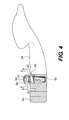
- FIG. 4 is a cross-sectional view of the shift lever of FIG. 1 showing a cam rotatably supported by a cam seat supported on the lever;
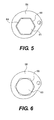
- FIG. 5 is a cross-sectional view of the cam engaged with an engaging portion of a post of the reach adjust mechanism taken along line 5-5 of FIG. 4 ;
- FIG. 6 is a cross-sectional view of the cam engaged with a non-engaging portion of the post of the reach adjust mechanism taken along line 6-6 of FIG. 4 ;
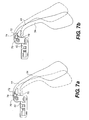
- FIG. 7a and 7b are side views of a shift lever having a reach adjust mechanism according to another embodiment of the present invention showing two rest positions of the shift lever.
- FIGS. 1 and 2 illustrate a bicycle control apparatus 10 including a brake lever assembly 12 and a shift lever assembly 14.
- the shift lever assembly 14 includes a reach adjust mechanism 16 according to one embodiment of the present invention.
- the brake lever assembly 12 may also be configured to include the reach adjust mechanism 16.
- the brake lever assembly 12 is integrated with the shift lever assembly 14.
- the brake lever assembly 12 may be separate from the shift lever assembly 14.
- the bicycle control apparatus 10 includes a housing 18 that is mountable to a handlebar 20, typically a drop-style handlebar found on a road bike, by a clamp 22.
- the brake lever assembly 12 includes a brake lever 24 pivotable about a shaft or pivot axis 26 and biased toward a rest position by a preloaded return spring.
- the brake lever 24 includes a finger grip 28 and a cable seat 30 for receiving one end of a brake cable 32.
- the other end of the brake cable 32 is connected to a brake device (not shown).
- the brake lever 24 is pivotable toward the handlebar 20, pulling the brake cable 32 to slow the bicycle.
- the shift lever assembly 14 generally includes a shifter lever 34, the reach adjust mechanism 16 and a cable spool 36 for pulling and releasing a control cable 38 connected to a gear change mechanism (not shown) to shift between various gear positions.
- the gear change mechanism may be a derailleur or other external or internal gear change devices.
- the shift lever 34 is biased toward a rest position by a preloaded shift lever return spring 40 and preferably tucked behind the brake lever 24.
- the shift lever 34 includes a first portion 42 rotatably mounted to a shaft or first axis 44, and a second portion 46 preferably paddle-shaped for easy reach by the rider's fingers.
- the first portion 42 is operatively connected to the cable spool 36 to rotate the spool 36 to shift between gear positions.
- the second portion 46 of the shift lever 34 is configured to rotate about the shaft 44 along with the first portion 42, the first portion 42 functioning as a support member for the second portion 46. Separately, the second portion rotates about a lever shaft or second axis 48 mounted to the first portion 44 of the shift lever 34.
- the second axis 48 may lie in a plane substantially perpendicular to the first axis 44. Alternatively, the second axis need not lie in a plane substantially perpendicular to the first axis, for example, it may be parallel to the brake axis 26.
- the second portion 46 of the shift lever 34 is biased by a preloaded return spring 50 mounted coaxially with the lever shaft 48. In this embodiment, second portion 46 of the shift lever 34 moves with the brake lever 24 when the brake lever 24 is pivoted toward the handlebar 20. Further, the second portion 46 of the shift lever 34 is pivotable toward the handlebar 20 independently of the brake lever 24.
- the cable spool 36 is rotatably mounted on the shaft 44 and includes a groove 52 along its periphery, for receiving the control cable 38.
- the cable spool 36 is biased in the cable-release direction by tension in the control cable 38 and, preferably, by a cable spool return spring 54.
- the cable spool return spring 54 is disposed between the cable spool 38 and the housing 18.
- the reach adjust mechanism 16 includes a follower 56, a cam 58 and a cam seat 60 for maintaining the cam 58 in a current user-selectable position.
- the follower 56 in this embodiment a bracket, is fixedly supported on the first portion 42 of the shift lever 34 at one end, and engages the cam 58 at the other end.
- the cam 58 has a variable diameter, a different diameter corresponding to each of the user-selectable position.
- the cam 58 is rotatable to change the user-selectable position of the cam 58, resulting in a different rest position of the shift lever 34 for each user-selectable position.
- the cam seat 60 further includes a post 62 that is connected to the shift lever 34.
- the post 62 includes an engaging portion 61 and a non-engaging portion 63 (see FIGS. 5 and 6 ).
- the cam includes a bore for receiving the post 62 therethrough.
- the cam 58 is user-positionable on the post 62 between the engaging and non-engaging portions 61, 63.
- the engaging portion 61 maintains the cam 58 in a current user-selectable position and the non-engaging portion 63 permits the rotation of the cam 58 between the user-selectable positions.
- the engaging portion 61 has a hexagonal outer surface 64 engageable with a mating inner hexagonal surface 66 on the cam 58 (see FIG. 5 ).
- the engaging portion 61 and cam 58 may have any non-circular shape that prevents the cam 58 from rotating but allows axial movement of the cam 58 along the post 62.
- a spring 68 in this embodiment a compression spring, biases the cam 58 toward the engaging portion 61 of the post 62.
- a retaining ring 69 retains the cam 58 on the post 62.
- the user may adjust the distance between the shift lever 34 and the handlebar 20 by first positioning the cam 58 at the non-engaging portion 63 of the post 62. The user then rotates the cam 58 to a next user-selectable position to position the shift lever 34 closer or further away from the handlebar 20. Counterclockwise rotation of the cam 58 incrementally positions the shift lever 34 closer to the handlebar 20 until the largest cam diameter is reached; further counterclockwise rotation of the cam 58 then drops the shift lever 34 to its farthest position from the handlebar 20.
- the dashed lines show the shift lever 34 in a reduced-reach rest position, a distance A from the handlebar 20.
- the solid lines show the shift lever 34 in an extended-reach rest position, a distance B from the handlebar 20.
- FIGS. 3a and 3b also show the shift lever 34 in two rest positions.
- FIGS. 7a and 7b illustrates another embodiment of a reach adjust mechanism 70 for the shift lever 34, similar to the reach adjust mechanism 16 shown in FIG. 1-6 , except that a follower 72 is fixedly supported on the shift lever 34 and a cam 74 is rotatably supported on the support member, in this embodiment the first portion 42 of the shift lever 34.
- the cam seat 76 is supported on the first portion 42 of the shift lever 34.
- the cam 74 has a variable diameter, a different diameter corresponding to each of the user-selectable position.
- the cam 74 is rotatable to change the user-selectable position of the cam 74, resulting in a different rest position of the shift lever 34 for each user-selectable position.
- FIGS. 7a and 7b show the shift lever 34 in two rest positions.
Landscapes
- Engineering & Computer Science (AREA)
- Mechanical Engineering (AREA)
- Mechanical Control Devices (AREA)
- Steering Devices For Bicycles And Motorcycles (AREA)
Abstract
Description
- The present invention relates to handlebar-mounted lever assemblies, and more particularly, to a lever assembly that includes a reach adjust mechanism.
- Typically, a lever assembly may be a brake lever assembly or a shift lever assembly. These assemblies are mountable to a handlebar for use on a bicycle, and the like, to actuate a control cable extending between the lever assembly and a brake or gear-change device. Alternatively, the lever assembly may be used in a hydraulic brake system or the like. Typically, the distance between the lever and the handlebar, known as the reach, is fixed and set to accommodate an average-sized hand. Accordingly, a fixed-reach lever may be positioned too far from the handlebar for a rider with smaller hands to comfortably reach.
- To solve this problem, the lever assembly may include a reach adjust mechanism. One example of a reach adjust mechanism is a removable spacer insertable between the housing and the lever. One disadvantage of the spacers is that they provide only one increment of reach adjust. Another disadvantage is that the discrete spacer may be lost. Another example of a reach adjust mechanism is a screw or bolt threaded directly into the housing and engageable with the lever to position the lever relative to the handlebar. However, when the threads on the housing become worn or stripped, the entire housing has to be replaced. Therefore, there is a need for a lever reach adjust mechanism that overcomes these disadvantages.
- The present invention provides a reach-adjustable lever assembly mountable to a handlebar for actuating one of a gear-change and braking device. The reach-adjustable lever assembly generally includes a support member, a lever and a reach adjust mechanism. The lever is pivotably connected to the support member. The reach adjust mechanism includes a follower, a cam and a cam seat. The follower is fixedly supported on one of the support member and the lever. The cam is rotatably supported on the other of the support member and the lever and has a plurality of user-selectable positions. The cam seat retains the cam in a current user-selectable position. The lever is pivotably biased toward a rest position to position the cam against the follower. The cam and the follower are configured to provide a different lever rest position for each of the user-selectable positions.
- In one embodiment of the present invention, the cam seat includes a post having an engaging portion and a non-engaging portion. The cam is positionable on the post between the engaging and non-engaging portions. The engaging portion retains the cam in the current user-selectable position and the non-engaging portion permits rotation of the cam between the user-selectable positions. To prevent rotation between the engaging portion and the cam, the cam includes a non-circular inner surface matingly engageable with a complimentary-shaped non-circular outer surface of the engaging portion. Further, a spring biases the cam toward the engaging portion, while a retaining ring maintains the cam on the post.
- These and other features and advantages of the present invention will be more fully understood from the following description of one or more embodiments of the invention, taken together with the accompanying drawings.
- In the drawings:
-
FIG. 1 is a side view of a bicycle control apparatus including a shift lever assembly having a reach adjust mechanism according to one embodiment of the present invention with a housing partially cut away and showing two rest positions of the shift lever relative to a handlebar; -
FIG. 2 is a cross-sectional view of the shift lever assembly ofFIG. 1 ; -
FIG. 3a and 3b are side views of a shift lever and the reach adjust mechanism ofFIG. 1 showing two rest positions of the shift lever; -
FIG. 4 is a cross-sectional view of the shift lever ofFIG. 1 showing a cam rotatably supported by a cam seat supported on the lever; -
FIG. 5 is a cross-sectional view of the cam engaged with an engaging portion of a post of the reach adjust mechanism taken along line 5-5 ofFIG. 4 ; -
FIG. 6 is a cross-sectional view of the cam engaged with a non-engaging portion of the post of the reach adjust mechanism taken along line 6-6 ofFIG. 4 ; and -
FIG. 7a and 7b are side views of a shift lever having a reach adjust mechanism according to another embodiment of the present invention showing two rest positions of the shift lever. -
FIGS. 1 and2 illustrate abicycle control apparatus 10 including abrake lever assembly 12 and ashift lever assembly 14. Theshift lever assembly 14 includes a reach adjustmechanism 16 according to one embodiment of the present invention. Alternatively, thebrake lever assembly 12 may also be configured to include the reach adjustmechanism 16. In this embodiment, thebrake lever assembly 12 is integrated with theshift lever assembly 14. Alternatively, thebrake lever assembly 12 may be separate from theshift lever assembly 14. Thebicycle control apparatus 10 includes ahousing 18 that is mountable to ahandlebar 20, typically a drop-style handlebar found on a road bike, by aclamp 22. Thebrake lever assembly 12 includes abrake lever 24 pivotable about a shaft orpivot axis 26 and biased toward a rest position by a preloaded return spring. Thebrake lever 24 includes afinger grip 28 and acable seat 30 for receiving one end of abrake cable 32. The other end of thebrake cable 32 is connected to a brake device (not shown). Thebrake lever 24 is pivotable toward thehandlebar 20, pulling thebrake cable 32 to slow the bicycle. - The
shift lever assembly 14 generally includes ashifter lever 34, the reach adjustmechanism 16 and acable spool 36 for pulling and releasing acontrol cable 38 connected to a gear change mechanism (not shown) to shift between various gear positions. The gear change mechanism may be a derailleur or other external or internal gear change devices. Theshift lever 34 is biased toward a rest position by a preloaded shiftlever return spring 40 and preferably tucked behind thebrake lever 24. Theshift lever 34 includes afirst portion 42 rotatably mounted to a shaft orfirst axis 44, and asecond portion 46 preferably paddle-shaped for easy reach by the rider's fingers. Thefirst portion 42 is operatively connected to thecable spool 36 to rotate thespool 36 to shift between gear positions. Thesecond portion 46 of theshift lever 34 is configured to rotate about theshaft 44 along with thefirst portion 42, thefirst portion 42 functioning as a support member for thesecond portion 46. Separately, the second portion rotates about a lever shaft orsecond axis 48 mounted to thefirst portion 44 of theshift lever 34. Thesecond axis 48 may lie in a plane substantially perpendicular to thefirst axis 44. Alternatively, the second axis need not lie in a plane substantially perpendicular to the first axis, for example, it may be parallel to thebrake axis 26. Thesecond portion 46 of theshift lever 34 is biased by a preloadedreturn spring 50 mounted coaxially with thelever shaft 48. In this embodiment,second portion 46 of theshift lever 34 moves with thebrake lever 24 when thebrake lever 24 is pivoted toward thehandlebar 20. Further, thesecond portion 46 of theshift lever 34 is pivotable toward thehandlebar 20 independently of thebrake lever 24. - The
cable spool 36 is rotatably mounted on theshaft 44 and includes agroove 52 along its periphery, for receiving thecontrol cable 38. Thecable spool 36 is biased in the cable-release direction by tension in thecontrol cable 38 and, preferably, by a cablespool return spring 54. The cablespool return spring 54 is disposed between thecable spool 38 and thehousing 18. - Looking to
FIGS. 3a, 3b and4 , the reach adjustmechanism 16 includes afollower 56, acam 58 and acam seat 60 for maintaining thecam 58 in a current user-selectable position. Thefollower 56, in this embodiment a bracket, is fixedly supported on thefirst portion 42 of theshift lever 34 at one end, and engages thecam 58 at the other end. Thecam 58 has a variable diameter, a different diameter corresponding to each of the user-selectable position. Thecam 58 is rotatable to change the user-selectable position of thecam 58, resulting in a different rest position of theshift lever 34 for each user-selectable position. - The
cam seat 60 further includes apost 62 that is connected to theshift lever 34. Thepost 62 includes an engagingportion 61 and a non-engaging portion 63 (seeFIGS. 5 and 6 ). The cam includes a bore for receiving thepost 62 therethrough. Thecam 58 is user-positionable on thepost 62 between the engaging andnon-engaging portions portion 61 maintains thecam 58 in a current user-selectable position and thenon-engaging portion 63 permits the rotation of thecam 58 between the user-selectable positions. To prevent rotation between the engagingportion 61 of thepost 62 and thecam 58, the engagingportion 61 has a hexagonalouter surface 64 engageable with a mating innerhexagonal surface 66 on the cam 58 (seeFIG. 5 ). Alternatively, the engagingportion 61 andcam 58 may have any non-circular shape that prevents thecam 58 from rotating but allows axial movement of thecam 58 along thepost 62. Aspring 68, in this embodiment a compression spring, biases thecam 58 toward the engagingportion 61 of thepost 62. A retainingring 69 retains thecam 58 on thepost 62. - In this embodiment, the user may adjust the distance between the
shift lever 34 and thehandlebar 20 by first positioning thecam 58 at thenon-engaging portion 63 of thepost 62. The user then rotates thecam 58 to a next user-selectable position to position theshift lever 34 closer or further away from thehandlebar 20. Counterclockwise rotation of thecam 58 incrementally positions theshift lever 34 closer to thehandlebar 20 until the largest cam diameter is reached; further counterclockwise rotation of thecam 58 then drops theshift lever 34 to its farthest position from thehandlebar 20. InFIG. 1 , the dashed lines show theshift lever 34 in a reduced-reach rest position, a distance A from thehandlebar 20. The solid lines show theshift lever 34 in an extended-reach rest position, a distance B from thehandlebar 20.FIGS. 3a and 3b also show theshift lever 34 in two rest positions. -
FIGS. 7a and 7b illustrates another embodiment of a reach adjustmechanism 70 for theshift lever 34, similar to the reach adjustmechanism 16 shown inFIG. 1-6 , except that afollower 72 is fixedly supported on theshift lever 34 and acam 74 is rotatably supported on the support member, in this embodiment thefirst portion 42 of theshift lever 34. Thecam seat 76 is supported on thefirst portion 42 of theshift lever 34. Thecam 74 has a variable diameter, a different diameter corresponding to each of the user-selectable position. Thecam 74 is rotatable to change the user-selectable position of thecam 74, resulting in a different rest position of theshift lever 34 for each user-selectable position.FIGS. 7a and 7b show theshift lever 34 in two rest positions. - While this invention has been described by reference to one or more preferred embodiments, it should be understood that numerous changes could be made within the spirit and scope of the inventive concepts described. Accordingly, it is intended that the invention not be limited to the disclosed embodiments, but that it have the full scope permitted by the language of the following claims.
Claims (11)
- A reach-adjustable lever assembly mountable to a handlebar for actuating one of a gear-change and braking device, the reach-adjustable lever assembly comprising:a support member;a lever pivotably connected to the support member; anda reach adjust mechanism including:a follower fixedly supported on one of the support member and the lever;a cam rotatably supported on the other of the support member and the lever, the cam having a plurality user-selectable positions; anda cam seat for retaining the cam in a current user-selectable position,the lever rotatably biased toward a rest position to position the cam against the follower, the cam and the follower configured to provide a different rest position of the lever for each of the user-selectable positions.
- A reach-adjustable lever assembly according to claim 1, wherein the follower is fixedly supported on the support member and the cam is rotatably supported on the lever.
- A reach-adjustable lever assembly according to claim 2, wherein the cam seat includes a post supported on the lever and having an engaging portion and a non-engaging portion, the cam is positionable on the post between the engaging and non-engaging portions, the engaging portion retaining the cam in the current user-selectable position, the non-engaging portion permitting rotation of the cam between the user-selectable positions, the cam biased toward the engaging portion.
- A reach-adjustable lever assembly according to claim 3, wherein the cam includes a non-circular inner surface matingly engageable with a complimentary-shaped non-circular outer surface of the engaging portion of the post to prevent relative rotation between the cam and the post.
- A reach-adjustable lever assembly according to claim 4, wherein a spring biases the cam toward the engaging portion of the post.
- A reach-adjustable lever assembly according to claim 5, wherein a retaining ring retains the cam on the post.
- A reach-adjustable lever assembly according to claim 1, wherein the follower is fixedly supported on the lever and the cam is rotatably supported on the support member.
- A reach-adjustable lever assembly according to claim 7, wherein the cam seat includes a post supported on the support member and having an engaging portion and a non-engaging portion, the cam is positionable on the post between the engaging and non-engaging portions, the engaging portion retaining the cam in the current user-selectable position, the non-engaging portion permitting rotation of the cam between the user-selectable positions, the cam biased toward the engaging portion.
- A reach-adjustable lever assembly according to claim 8, wherein the cam includes a non-circular inner surface matingly engageable with a complimentary-shaped non-circular outer surface of the engaging portion of the post to prevent relative rotation between the cam and the post.
- A reach-adjustable lever assembly according to claim 9, wherein a spring biases the cam toward the engaging portion of the post.
- A reach-adjustable lever assembly according to claim 10, wherein a retaining ring retains the cam on the post.
Applications Claiming Priority (1)
| Application Number | Priority Date | Filing Date | Title |
|---|---|---|---|
| US11/689,461 US8459142B2 (en) | 2007-03-21 | 2007-03-21 | Reach adjust for a handlebar-mounted lever assembly |
Publications (3)
| Publication Number | Publication Date |
|---|---|
| EP1972537A2 true EP1972537A2 (en) | 2008-09-24 |
| EP1972537A3 EP1972537A3 (en) | 2008-10-22 |
| EP1972537B1 EP1972537B1 (en) | 2009-12-09 |
Family
ID=39273312
Family Applications (1)
| Application Number | Title | Priority Date | Filing Date |
|---|---|---|---|
| EP08004471A Active EP1972537B1 (en) | 2007-03-21 | 2008-03-11 | Reach adjust for a handlebar-mounted lever assembly |
Country Status (5)
| Country | Link |
|---|---|
| US (1) | US8459142B2 (en) |
| EP (1) | EP1972537B1 (en) |
| CN (1) | CN101293554B (en) |
| DE (1) | DE602008000351D1 (en) |
| TW (1) | TWI340708B (en) |
Cited By (3)
| Publication number | Priority date | Publication date | Assignee | Title |
|---|---|---|---|---|
| EP2008923A1 (en) * | 2007-06-25 | 2008-12-31 | Shimano Inc. | Bicycle control device |
| EP3339155A1 (en) | 2016-12-23 | 2018-06-27 | Campagnolo S.r.l. | Control device for a bicycle |
| US11097804B2 (en) | 2016-11-04 | 2021-08-24 | Freni Brembo S.P.A. | Lever device |
Families Citing this family (10)
| Publication number | Priority date | Publication date | Assignee | Title |
|---|---|---|---|---|
| US7793565B2 (en) * | 2007-03-01 | 2010-09-14 | Sram, Llc | Reach adjustment for a handlebar-mounted lever assembly |
| ITMI20070400A1 (en) | 2007-03-01 | 2008-09-02 | Campagnolo Srl | COMMAND DEVICE FOR BICYCLE AND BICYCLE INCLUDING SUCH DIPSOSITIVE |
| US8943924B2 (en) | 2010-11-24 | 2015-02-03 | Hb Performance Systems, Inc. | System and method for an adjustable lever assembly |
| USD641670S1 (en) | 2010-11-24 | 2011-07-19 | Hb Performance Systems, Inc. | Brake pad |
| US8863612B2 (en) | 2011-08-22 | 2014-10-21 | Mon Spencer Owyang | Lever positioner assembly |
| US9090303B2 (en) * | 2012-05-18 | 2015-07-28 | Shimano Inc. | Bicycle control device |
| US9771129B2 (en) * | 2013-06-21 | 2017-09-26 | Shimano (Singapore) Pte. Ltd. | Bicycle control device |
| CN105000118B (en) * | 2014-04-24 | 2017-10-03 | 天心工业股份有限公司 | Brake handle is held away from adjustment structure |
| US9242695B2 (en) * | 2014-06-10 | 2016-01-26 | Tien Hsin Industries Co., Ltd. | Brake lever reach adjustment |
| US10189532B2 (en) * | 2016-07-12 | 2019-01-29 | Shimano Inc. | Bicycle operating device |
Citations (1)
| Publication number | Priority date | Publication date | Assignee | Title |
|---|---|---|---|---|
| JPH10129293A (en) | 1996-10-30 | 1998-05-19 | Asahi Denso Kk | Operation lever device for motorcycle |
Family Cites Families (16)
| Publication number | Priority date | Publication date | Assignee | Title |
|---|---|---|---|---|
| DE2434300A1 (en) | 1974-07-17 | 1976-01-29 | Weinmann & Co Kg | Adjustable brake lever for pedal cycles - has adjuster screw to determine distance between lever and handle bar grip |
| JPS5310676Y2 (en) * | 1975-08-01 | 1978-03-22 | ||
| US4348916A (en) * | 1979-07-02 | 1982-09-14 | Shimano Industrial Company Limited | Brake operating device for a bicycle |
| JPS60111786U (en) * | 1983-12-29 | 1985-07-29 | 株式会社シマノ | Bicycle brake control device |
| US5304719A (en) * | 1992-02-03 | 1994-04-19 | Pioneer Hi-Bred International, Inc. | Inbred corn line PHT47 |
| US5367109A (en) * | 1993-02-05 | 1994-11-22 | Pioneer Hi-Bred International, Inc. | Inbred corn line PHHB9 |
| JP2597741Y2 (en) * | 1993-07-21 | 1999-07-12 | 株式会社シマノ | Bicycle brake lever device |
| US5523520A (en) * | 1994-06-24 | 1996-06-04 | Goldsmith Seeds Inc. | Mutant dwarfism gene of petunia |
| DE9415887U1 (en) | 1994-10-04 | 1995-02-23 | ALESA Deutschland GmbH, 78244 Gottmadingen | Device for fixing a brake handle |
| US5850009A (en) * | 1997-01-29 | 1998-12-15 | Pioneer Hi-Bred International, Inc. | Inbred maize line PH0HC |
| US5968830A (en) * | 1997-03-28 | 1999-10-19 | Mississippi State University | Soybean transformation and regeneration methods |
| US5839544A (en) | 1997-05-19 | 1998-11-24 | Shimano Inc. | Brake lever having a rapid brake shoe clearance adjusting mechanism |
| JP2003261085A (en) | 2002-03-06 | 2003-09-16 | Nissin Kogyo Co Ltd | Operation lever for bar handle vehicle |
| JP3612304B2 (en) | 2002-03-07 | 2005-01-19 | 株式会社シマノ | Bicycle brake operating device |
| JP2005132262A (en) | 2003-10-31 | 2005-05-26 | Shimano Inc | Brake operation device for bicycle |
| US8061234B2 (en) | 2005-08-30 | 2011-11-22 | Roberto Lavezzi | Adjustment device for motorcycle master cylinders |
-
2007
- 2007-03-21 US US11/689,461 patent/US8459142B2/en not_active Expired - Fee Related
-
2008
- 2008-03-11 EP EP08004471A patent/EP1972537B1/en active Active
- 2008-03-11 DE DE602008000351T patent/DE602008000351D1/en active Active
- 2008-03-13 TW TW097108827A patent/TWI340708B/en active
- 2008-03-21 CN CN200810092095.9A patent/CN101293554B/en active Active
Patent Citations (1)
| Publication number | Priority date | Publication date | Assignee | Title |
|---|---|---|---|---|
| JPH10129293A (en) | 1996-10-30 | 1998-05-19 | Asahi Denso Kk | Operation lever device for motorcycle |
Cited By (3)
| Publication number | Priority date | Publication date | Assignee | Title |
|---|---|---|---|---|
| EP2008923A1 (en) * | 2007-06-25 | 2008-12-31 | Shimano Inc. | Bicycle control device |
| US11097804B2 (en) | 2016-11-04 | 2021-08-24 | Freni Brembo S.P.A. | Lever device |
| EP3339155A1 (en) | 2016-12-23 | 2018-06-27 | Campagnolo S.r.l. | Control device for a bicycle |
Also Published As
| Publication number | Publication date |
|---|---|
| CN101293554A (en) | 2008-10-29 |
| TW200911614A (en) | 2009-03-16 |
| DE602008000351D1 (en) | 2010-01-21 |
| TWI340708B (en) | 2011-04-21 |
| EP1972537A3 (en) | 2008-10-22 |
| US20080229863A1 (en) | 2008-09-25 |
| EP1972537B1 (en) | 2009-12-09 |
| US8459142B2 (en) | 2013-06-11 |
| CN101293554B (en) | 2010-07-21 |
Similar Documents
| Publication | Publication Date | Title |
|---|---|---|
| US8459142B2 (en) | Reach adjust for a handlebar-mounted lever assembly | |
| US7793565B2 (en) | Reach adjustment for a handlebar-mounted lever assembly | |
| US5476019A (en) | Rotatable handgrip actuating system | |
| EP1440878B1 (en) | Apparatus for shifting a bicycle transmission | |
| US9073596B2 (en) | Bicycle shifter | |
| EP2174862B1 (en) | Bicycle control device | |
| EP0758433B1 (en) | Adjustable leverage brake lever | |
| EP0810150B1 (en) | Bicycle shift control device | |
| CN100398392C (en) | Position Control Mechanisms for Bicycle Control Devices | |
| EP2075187B1 (en) | Bicycle shift operating device | |
| US9199688B2 (en) | Bicycle control device | |
| CN100372728C (en) | Shift and brake controls | |
| DE102007053534B4 (en) | Bicycle gear shifting means | |
| US9227689B2 (en) | Bicycle shift operating device | |
| EP2165925B1 (en) | Cable operating mechanism | |
| US7762157B2 (en) | Bicycle shift operating device with a multi-direction operating member | |
| EP2078667B1 (en) | Bicycle shift operating device | |
| US20020124678A1 (en) | Shifting device for a bicycle | |
| EP2157011A2 (en) | Cable operating mechanism | |
| US20030230160A1 (en) | Barend mounted twist shifter with integrated brake actuator for bicycle | |
| EP1452433B1 (en) | Twist grip for operating a bicycle transmission | |
| TWI869469B (en) | Bicycle operating device |
Legal Events
| Date | Code | Title | Description |
|---|---|---|---|
| PUAI | Public reference made under article 153(3) epc to a published international application that has entered the european phase |
Free format text: ORIGINAL CODE: 0009012 |
|
| PUAL | Search report despatched |
Free format text: ORIGINAL CODE: 0009013 |
|
| 17P | Request for examination filed |
Effective date: 20080311 |
|
| AK | Designated contracting states |
Kind code of ref document: A2 Designated state(s): AT BE BG CH CY CZ DE DK EE ES FI FR GB GR HR HU IE IS IT LI LT LU LV MC MT NL NO PL PT RO SE SI SK TR |
|
| AX | Request for extension of the european patent |
Extension state: AL BA MK RS |
|
| AK | Designated contracting states |
Kind code of ref document: A3 Designated state(s): AT BE BG CH CY CZ DE DK EE ES FI FR GB GR HR HU IE IS IT LI LT LU LV MC MT NL NO PL PT RO SE SI SK TR |
|
| AX | Request for extension of the european patent |
Extension state: AL BA MK RS |
|
| RAP1 | Party data changed (applicant data changed or rights of an application transferred) |
Owner name: SRAM, LLC. |
|
| 111Z | Information provided on other rights and legal means of execution |
Free format text: AT BE BG CH CY CZ DE DK EE ES FI FR GB GR HR HU IE IS IT LT LU LV MC MT NL NO PL PT RO SE SI SK TR Effective date: 20090106 |
|
| 17Q | First examination report despatched |
Effective date: 20090507 |
|
| GRAP | Despatch of communication of intention to grant a patent |
Free format text: ORIGINAL CODE: EPIDOSNIGR1 |
|
| AKX | Designation fees paid |
Designated state(s): DE FR NL |
|
| GRAS | Grant fee paid |
Free format text: ORIGINAL CODE: EPIDOSNIGR3 |
|
| GRAA | (expected) grant |
Free format text: ORIGINAL CODE: 0009210 |
|
| AK | Designated contracting states |
Kind code of ref document: B1 Designated state(s): DE FR NL |
|
| REF | Corresponds to: |
Ref document number: 602008000351 Country of ref document: DE Date of ref document: 20100121 Kind code of ref document: P |
|
| REG | Reference to a national code |
Ref country code: NL Ref legal event code: T3 |
|
| PLBE | No opposition filed within time limit |
Free format text: ORIGINAL CODE: 0009261 |
|
| STAA | Information on the status of an ep patent application or granted ep patent |
Free format text: STATUS: NO OPPOSITION FILED WITHIN TIME LIMIT |
|
| 26N | No opposition filed |
Effective date: 20100910 |
|
| PGFP | Annual fee paid to national office [announced via postgrant information from national office to epo] |
Ref country code: FR Payment date: 20130325 Year of fee payment: 6 |
|
| PGFP | Annual fee paid to national office [announced via postgrant information from national office to epo] |
Ref country code: NL Payment date: 20130309 Year of fee payment: 6 |
|
| REG | Reference to a national code |
Ref country code: NL Ref legal event code: V1 Effective date: 20141001 |
|
| REG | Reference to a national code |
Ref country code: FR Ref legal event code: ST Effective date: 20141128 |
|
| PG25 | Lapsed in a contracting state [announced via postgrant information from national office to epo] |
Ref country code: FR Free format text: LAPSE BECAUSE OF NON-PAYMENT OF DUE FEES Effective date: 20140331 |
|
| PG25 | Lapsed in a contracting state [announced via postgrant information from national office to epo] |
Ref country code: NL Free format text: LAPSE BECAUSE OF NON-PAYMENT OF DUE FEES Effective date: 20141001 |
|
| REG | Reference to a national code |
Ref country code: DE Ref legal event code: R082 Ref document number: 602008000351 Country of ref document: DE Representative=s name: THUM, MOETSCH, WEICKERT PATENTANWAELTE PARTG M, DE Ref country code: DE Ref legal event code: R082 Ref document number: 602008000351 Country of ref document: DE Representative=s name: THUM & PARTNER THUM MOETSCH WEICKERT PATENTANW, DE |
|
| P01 | Opt-out of the competence of the unified patent court (upc) registered |
Effective date: 20230524 |
|
| PGFP | Annual fee paid to national office [announced via postgrant information from national office to epo] |
Ref country code: DE Payment date: 20250210 Year of fee payment: 18 |