EP3339087A1 - Charging control apparatus for vehicle and charging control method for the same with capacity for regenerative charging on a downward slope - Google Patents
Charging control apparatus for vehicle and charging control method for the same with capacity for regenerative charging on a downward slope Download PDFInfo
- Publication number
- EP3339087A1 EP3339087A1 EP17210572.8A EP17210572A EP3339087A1 EP 3339087 A1 EP3339087 A1 EP 3339087A1 EP 17210572 A EP17210572 A EP 17210572A EP 3339087 A1 EP3339087 A1 EP 3339087A1
- Authority
- EP
- European Patent Office
- Prior art keywords
- soc
- electric power
- vehicle
- controller
- target value
- Prior art date
- Legal status (The legal status is an assumption and is not a legal conclusion. Google has not performed a legal analysis and makes no representation as to the accuracy of the status listed.)
- Granted
Links
Images




Classifications
-
- B—PERFORMING OPERATIONS; TRANSPORTING
- B60—VEHICLES IN GENERAL
- B60L—PROPULSION OF ELECTRICALLY-PROPELLED VEHICLES; SUPPLYING ELECTRIC POWER FOR AUXILIARY EQUIPMENT OF ELECTRICALLY-PROPELLED VEHICLES; ELECTRODYNAMIC BRAKE SYSTEMS FOR VEHICLES IN GENERAL; MAGNETIC SUSPENSION OR LEVITATION FOR VEHICLES; MONITORING OPERATING VARIABLES OF ELECTRICALLY-PROPELLED VEHICLES; ELECTRIC SAFETY DEVICES FOR ELECTRICALLY-PROPELLED VEHICLES
- B60L53/00—Methods of charging batteries, specially adapted for electric vehicles; Charging stations or on-board charging equipment therefor; Exchange of energy storage elements in electric vehicles
- B60L53/60—Monitoring or controlling charging stations
- B60L53/66—Data transfer between charging stations and vehicles
-
- B—PERFORMING OPERATIONS; TRANSPORTING
- B60—VEHICLES IN GENERAL
- B60L—PROPULSION OF ELECTRICALLY-PROPELLED VEHICLES; SUPPLYING ELECTRIC POWER FOR AUXILIARY EQUIPMENT OF ELECTRICALLY-PROPELLED VEHICLES; ELECTRODYNAMIC BRAKE SYSTEMS FOR VEHICLES IN GENERAL; MAGNETIC SUSPENSION OR LEVITATION FOR VEHICLES; MONITORING OPERATING VARIABLES OF ELECTRICALLY-PROPELLED VEHICLES; ELECTRIC SAFETY DEVICES FOR ELECTRICALLY-PROPELLED VEHICLES
- B60L58/00—Methods or circuit arrangements for monitoring or controlling batteries or fuel cells, specially adapted for electric vehicles
- B60L58/10—Methods or circuit arrangements for monitoring or controlling batteries or fuel cells, specially adapted for electric vehicles for monitoring or controlling batteries
- B60L58/12—Methods or circuit arrangements for monitoring or controlling batteries or fuel cells, specially adapted for electric vehicles for monitoring or controlling batteries responding to state of charge [SoC]
-
- B—PERFORMING OPERATIONS; TRANSPORTING
- B60—VEHICLES IN GENERAL
- B60L—PROPULSION OF ELECTRICALLY-PROPELLED VEHICLES; SUPPLYING ELECTRIC POWER FOR AUXILIARY EQUIPMENT OF ELECTRICALLY-PROPELLED VEHICLES; ELECTRODYNAMIC BRAKE SYSTEMS FOR VEHICLES IN GENERAL; MAGNETIC SUSPENSION OR LEVITATION FOR VEHICLES; MONITORING OPERATING VARIABLES OF ELECTRICALLY-PROPELLED VEHICLES; ELECTRIC SAFETY DEVICES FOR ELECTRICALLY-PROPELLED VEHICLES
- B60L53/00—Methods of charging batteries, specially adapted for electric vehicles; Charging stations or on-board charging equipment therefor; Exchange of energy storage elements in electric vehicles
- B60L53/60—Monitoring or controlling charging stations
-
- B—PERFORMING OPERATIONS; TRANSPORTING
- B60—VEHICLES IN GENERAL
- B60L—PROPULSION OF ELECTRICALLY-PROPELLED VEHICLES; SUPPLYING ELECTRIC POWER FOR AUXILIARY EQUIPMENT OF ELECTRICALLY-PROPELLED VEHICLES; ELECTRODYNAMIC BRAKE SYSTEMS FOR VEHICLES IN GENERAL; MAGNETIC SUSPENSION OR LEVITATION FOR VEHICLES; MONITORING OPERATING VARIABLES OF ELECTRICALLY-PROPELLED VEHICLES; ELECTRIC SAFETY DEVICES FOR ELECTRICALLY-PROPELLED VEHICLES
- B60L58/00—Methods or circuit arrangements for monitoring or controlling batteries or fuel cells, specially adapted for electric vehicles
- B60L58/10—Methods or circuit arrangements for monitoring or controlling batteries or fuel cells, specially adapted for electric vehicles for monitoring or controlling batteries
- B60L58/12—Methods or circuit arrangements for monitoring or controlling batteries or fuel cells, specially adapted for electric vehicles for monitoring or controlling batteries responding to state of charge [SoC]
- B60L58/13—Maintaining the SoC within a determined range
-
- B—PERFORMING OPERATIONS; TRANSPORTING
- B60—VEHICLES IN GENERAL
- B60W—CONJOINT CONTROL OF VEHICLE SUB-UNITS OF DIFFERENT TYPE OR DIFFERENT FUNCTION; CONTROL SYSTEMS SPECIALLY ADAPTED FOR HYBRID VEHICLES; ROAD VEHICLE DRIVE CONTROL SYSTEMS FOR PURPOSES NOT RELATED TO THE CONTROL OF A PARTICULAR SUB-UNIT
- B60W20/00—Control systems specially adapted for hybrid vehicles
- B60W20/10—Controlling the power contribution of each of the prime movers to meet required power demand
- B60W20/12—Controlling the power contribution of each of the prime movers to meet required power demand using control strategies taking into account route information
-
- B—PERFORMING OPERATIONS; TRANSPORTING
- B60—VEHICLES IN GENERAL
- B60W—CONJOINT CONTROL OF VEHICLE SUB-UNITS OF DIFFERENT TYPE OR DIFFERENT FUNCTION; CONTROL SYSTEMS SPECIALLY ADAPTED FOR HYBRID VEHICLES; ROAD VEHICLE DRIVE CONTROL SYSTEMS FOR PURPOSES NOT RELATED TO THE CONTROL OF A PARTICULAR SUB-UNIT
- B60W20/00—Control systems specially adapted for hybrid vehicles
- B60W20/10—Controlling the power contribution of each of the prime movers to meet required power demand
- B60W20/13—Controlling the power contribution of each of the prime movers to meet required power demand in order to stay within battery power input or output limits; in order to prevent overcharging or battery depletion
-
- B—PERFORMING OPERATIONS; TRANSPORTING
- B60—VEHICLES IN GENERAL
- B60W—CONJOINT CONTROL OF VEHICLE SUB-UNITS OF DIFFERENT TYPE OR DIFFERENT FUNCTION; CONTROL SYSTEMS SPECIALLY ADAPTED FOR HYBRID VEHICLES; ROAD VEHICLE DRIVE CONTROL SYSTEMS FOR PURPOSES NOT RELATED TO THE CONTROL OF A PARTICULAR SUB-UNIT
- B60W20/00—Control systems specially adapted for hybrid vehicles
- B60W20/10—Controlling the power contribution of each of the prime movers to meet required power demand
- B60W20/13—Controlling the power contribution of each of the prime movers to meet required power demand in order to stay within battery power input or output limits; in order to prevent overcharging or battery depletion
- B60W20/14—Controlling the power contribution of each of the prime movers to meet required power demand in order to stay within battery power input or output limits; in order to prevent overcharging or battery depletion in conjunction with braking regeneration
-
- B—PERFORMING OPERATIONS; TRANSPORTING
- B60—VEHICLES IN GENERAL
- B60W—CONJOINT CONTROL OF VEHICLE SUB-UNITS OF DIFFERENT TYPE OR DIFFERENT FUNCTION; CONTROL SYSTEMS SPECIALLY ADAPTED FOR HYBRID VEHICLES; ROAD VEHICLE DRIVE CONTROL SYSTEMS FOR PURPOSES NOT RELATED TO THE CONTROL OF A PARTICULAR SUB-UNIT
- B60W50/00—Details of control systems for road vehicle drive control not related to the control of a particular sub-unit, e.g. process diagnostic or vehicle driver interfaces
- B60W50/0097—Predicting future conditions
-
- B—PERFORMING OPERATIONS; TRANSPORTING
- B60—VEHICLES IN GENERAL
- B60L—PROPULSION OF ELECTRICALLY-PROPELLED VEHICLES; SUPPLYING ELECTRIC POWER FOR AUXILIARY EQUIPMENT OF ELECTRICALLY-PROPELLED VEHICLES; ELECTRODYNAMIC BRAKE SYSTEMS FOR VEHICLES IN GENERAL; MAGNETIC SUSPENSION OR LEVITATION FOR VEHICLES; MONITORING OPERATING VARIABLES OF ELECTRICALLY-PROPELLED VEHICLES; ELECTRIC SAFETY DEVICES FOR ELECTRICALLY-PROPELLED VEHICLES
- B60L2240/00—Control parameters of input or output; Target parameters
- B60L2240/60—Navigation input
- B60L2240/62—Vehicle position
- B60L2240/622—Vehicle position by satellite navigation
-
- B—PERFORMING OPERATIONS; TRANSPORTING
- B60—VEHICLES IN GENERAL
- B60L—PROPULSION OF ELECTRICALLY-PROPELLED VEHICLES; SUPPLYING ELECTRIC POWER FOR AUXILIARY EQUIPMENT OF ELECTRICALLY-PROPELLED VEHICLES; ELECTRODYNAMIC BRAKE SYSTEMS FOR VEHICLES IN GENERAL; MAGNETIC SUSPENSION OR LEVITATION FOR VEHICLES; MONITORING OPERATING VARIABLES OF ELECTRICALLY-PROPELLED VEHICLES; ELECTRIC SAFETY DEVICES FOR ELECTRICALLY-PROPELLED VEHICLES
- B60L2240/00—Control parameters of input or output; Target parameters
- B60L2240/70—Interactions with external data bases, e.g. traffic centres
-
- B—PERFORMING OPERATIONS; TRANSPORTING
- B60—VEHICLES IN GENERAL
- B60L—PROPULSION OF ELECTRICALLY-PROPELLED VEHICLES; SUPPLYING ELECTRIC POWER FOR AUXILIARY EQUIPMENT OF ELECTRICALLY-PROPELLED VEHICLES; ELECTRODYNAMIC BRAKE SYSTEMS FOR VEHICLES IN GENERAL; MAGNETIC SUSPENSION OR LEVITATION FOR VEHICLES; MONITORING OPERATING VARIABLES OF ELECTRICALLY-PROPELLED VEHICLES; ELECTRIC SAFETY DEVICES FOR ELECTRICALLY-PROPELLED VEHICLES
- B60L2260/00—Operating Modes
- B60L2260/40—Control modes
- B60L2260/50—Control modes by future state prediction
- B60L2260/54—Energy consumption estimation
-
- B—PERFORMING OPERATIONS; TRANSPORTING
- B60—VEHICLES IN GENERAL
- B60L—PROPULSION OF ELECTRICALLY-PROPELLED VEHICLES; SUPPLYING ELECTRIC POWER FOR AUXILIARY EQUIPMENT OF ELECTRICALLY-PROPELLED VEHICLES; ELECTRODYNAMIC BRAKE SYSTEMS FOR VEHICLES IN GENERAL; MAGNETIC SUSPENSION OR LEVITATION FOR VEHICLES; MONITORING OPERATING VARIABLES OF ELECTRICALLY-PROPELLED VEHICLES; ELECTRIC SAFETY DEVICES FOR ELECTRICALLY-PROPELLED VEHICLES
- B60L7/00—Electrodynamic brake systems for vehicles in general
- B60L7/10—Dynamic electric regenerative braking
-
- B—PERFORMING OPERATIONS; TRANSPORTING
- B60—VEHICLES IN GENERAL
- B60W—CONJOINT CONTROL OF VEHICLE SUB-UNITS OF DIFFERENT TYPE OR DIFFERENT FUNCTION; CONTROL SYSTEMS SPECIALLY ADAPTED FOR HYBRID VEHICLES; ROAD VEHICLE DRIVE CONTROL SYSTEMS FOR PURPOSES NOT RELATED TO THE CONTROL OF A PARTICULAR SUB-UNIT
- B60W2510/00—Input parameters relating to a particular sub-units
- B60W2510/24—Energy storage means
- B60W2510/242—Energy storage means for electrical energy
- B60W2510/244—Charge state
-
- B—PERFORMING OPERATIONS; TRANSPORTING
- B60—VEHICLES IN GENERAL
- B60W—CONJOINT CONTROL OF VEHICLE SUB-UNITS OF DIFFERENT TYPE OR DIFFERENT FUNCTION; CONTROL SYSTEMS SPECIALLY ADAPTED FOR HYBRID VEHICLES; ROAD VEHICLE DRIVE CONTROL SYSTEMS FOR PURPOSES NOT RELATED TO THE CONTROL OF A PARTICULAR SUB-UNIT
- B60W2556/00—Input parameters relating to data
- B60W2556/45—External transmission of data to or from the vehicle
- B60W2556/50—External transmission of data to or from the vehicle of positioning data, e.g. GPS [Global Positioning System] data
-
- B—PERFORMING OPERATIONS; TRANSPORTING
- B60—VEHICLES IN GENERAL
- B60W—CONJOINT CONTROL OF VEHICLE SUB-UNITS OF DIFFERENT TYPE OR DIFFERENT FUNCTION; CONTROL SYSTEMS SPECIALLY ADAPTED FOR HYBRID VEHICLES; ROAD VEHICLE DRIVE CONTROL SYSTEMS FOR PURPOSES NOT RELATED TO THE CONTROL OF A PARTICULAR SUB-UNIT
- B60W2710/00—Output or target parameters relating to a particular sub-units
- B60W2710/24—Energy storage means
- B60W2710/242—Energy storage means for electrical energy
- B60W2710/244—Charge state
-
- Y—GENERAL TAGGING OF NEW TECHNOLOGICAL DEVELOPMENTS; GENERAL TAGGING OF CROSS-SECTIONAL TECHNOLOGIES SPANNING OVER SEVERAL SECTIONS OF THE IPC; TECHNICAL SUBJECTS COVERED BY FORMER USPC CROSS-REFERENCE ART COLLECTIONS [XRACs] AND DIGESTS
- Y02—TECHNOLOGIES OR APPLICATIONS FOR MITIGATION OR ADAPTATION AGAINST CLIMATE CHANGE
- Y02T—CLIMATE CHANGE MITIGATION TECHNOLOGIES RELATED TO TRANSPORTATION
- Y02T10/00—Road transport of goods or passengers
- Y02T10/60—Other road transportation technologies with climate change mitigation effect
- Y02T10/62—Hybrid vehicles
-
- Y—GENERAL TAGGING OF NEW TECHNOLOGICAL DEVELOPMENTS; GENERAL TAGGING OF CROSS-SECTIONAL TECHNOLOGIES SPANNING OVER SEVERAL SECTIONS OF THE IPC; TECHNICAL SUBJECTS COVERED BY FORMER USPC CROSS-REFERENCE ART COLLECTIONS [XRACs] AND DIGESTS
- Y02—TECHNOLOGIES OR APPLICATIONS FOR MITIGATION OR ADAPTATION AGAINST CLIMATE CHANGE
- Y02T—CLIMATE CHANGE MITIGATION TECHNOLOGIES RELATED TO TRANSPORTATION
- Y02T10/00—Road transport of goods or passengers
- Y02T10/60—Other road transportation technologies with climate change mitigation effect
- Y02T10/70—Energy storage systems for electromobility, e.g. batteries
-
- Y—GENERAL TAGGING OF NEW TECHNOLOGICAL DEVELOPMENTS; GENERAL TAGGING OF CROSS-SECTIONAL TECHNOLOGIES SPANNING OVER SEVERAL SECTIONS OF THE IPC; TECHNICAL SUBJECTS COVERED BY FORMER USPC CROSS-REFERENCE ART COLLECTIONS [XRACs] AND DIGESTS
- Y02—TECHNOLOGIES OR APPLICATIONS FOR MITIGATION OR ADAPTATION AGAINST CLIMATE CHANGE
- Y02T—CLIMATE CHANGE MITIGATION TECHNOLOGIES RELATED TO TRANSPORTATION
- Y02T10/00—Road transport of goods or passengers
- Y02T10/60—Other road transportation technologies with climate change mitigation effect
- Y02T10/7072—Electromobility specific charging systems or methods for batteries, ultracapacitors, supercapacitors or double-layer capacitors
-
- Y—GENERAL TAGGING OF NEW TECHNOLOGICAL DEVELOPMENTS; GENERAL TAGGING OF CROSS-SECTIONAL TECHNOLOGIES SPANNING OVER SEVERAL SECTIONS OF THE IPC; TECHNICAL SUBJECTS COVERED BY FORMER USPC CROSS-REFERENCE ART COLLECTIONS [XRACs] AND DIGESTS
- Y02—TECHNOLOGIES OR APPLICATIONS FOR MITIGATION OR ADAPTATION AGAINST CLIMATE CHANGE
- Y02T—CLIMATE CHANGE MITIGATION TECHNOLOGIES RELATED TO TRANSPORTATION
- Y02T90/00—Enabling technologies or technologies with a potential or indirect contribution to GHG emissions mitigation
- Y02T90/10—Technologies relating to charging of electric vehicles
- Y02T90/12—Electric charging stations
-
- Y—GENERAL TAGGING OF NEW TECHNOLOGICAL DEVELOPMENTS; GENERAL TAGGING OF CROSS-SECTIONAL TECHNOLOGIES SPANNING OVER SEVERAL SECTIONS OF THE IPC; TECHNICAL SUBJECTS COVERED BY FORMER USPC CROSS-REFERENCE ART COLLECTIONS [XRACs] AND DIGESTS
- Y02—TECHNOLOGIES OR APPLICATIONS FOR MITIGATION OR ADAPTATION AGAINST CLIMATE CHANGE
- Y02T—CLIMATE CHANGE MITIGATION TECHNOLOGIES RELATED TO TRANSPORTATION
- Y02T90/00—Enabling technologies or technologies with a potential or indirect contribution to GHG emissions mitigation
- Y02T90/10—Technologies relating to charging of electric vehicles
- Y02T90/16—Information or communication technologies improving the operation of electric vehicles
-
- Y—GENERAL TAGGING OF NEW TECHNOLOGICAL DEVELOPMENTS; GENERAL TAGGING OF CROSS-SECTIONAL TECHNOLOGIES SPANNING OVER SEVERAL SECTIONS OF THE IPC; TECHNICAL SUBJECTS COVERED BY FORMER USPC CROSS-REFERENCE ART COLLECTIONS [XRACs] AND DIGESTS
- Y02—TECHNOLOGIES OR APPLICATIONS FOR MITIGATION OR ADAPTATION AGAINST CLIMATE CHANGE
- Y02T—CLIMATE CHANGE MITIGATION TECHNOLOGIES RELATED TO TRANSPORTATION
- Y02T90/00—Enabling technologies or technologies with a potential or indirect contribution to GHG emissions mitigation
- Y02T90/10—Technologies relating to charging of electric vehicles
- Y02T90/16—Information or communication technologies improving the operation of electric vehicles
- Y02T90/167—Systems integrating technologies related to power network operation and communication or information technologies for supporting the interoperability of electric or hybrid vehicles, i.e. smartgrids as interface for battery charging of electric vehicles [EV] or hybrid vehicles [HEV]
-
- Y—GENERAL TAGGING OF NEW TECHNOLOGICAL DEVELOPMENTS; GENERAL TAGGING OF CROSS-SECTIONAL TECHNOLOGIES SPANNING OVER SEVERAL SECTIONS OF THE IPC; TECHNICAL SUBJECTS COVERED BY FORMER USPC CROSS-REFERENCE ART COLLECTIONS [XRACs] AND DIGESTS
- Y04—INFORMATION OR COMMUNICATION TECHNOLOGIES HAVING AN IMPACT ON OTHER TECHNOLOGY AREAS
- Y04S—SYSTEMS INTEGRATING TECHNOLOGIES RELATED TO POWER NETWORK OPERATION, COMMUNICATION OR INFORMATION TECHNOLOGIES FOR IMPROVING THE ELECTRICAL POWER GENERATION, TRANSMISSION, DISTRIBUTION, MANAGEMENT OR USAGE, i.e. SMART GRIDS
- Y04S30/00—Systems supporting specific end-user applications in the sector of transportation
- Y04S30/10—Systems supporting the interoperability of electric or hybrid vehicles
- Y04S30/12—Remote or cooperative charging
Definitions
- the present disclosure relates to a charging control apparatus for a vehicle and a charging control method for the same, in which the vehicle is capable of storing electric power in an in-vehicle electric power storage device and the electric power is supplied from an electric power supply on the outside of a vehicle (hereinafter also referred to as "external charging").
- JP 2012-181183 A An information communication system that includes an in-vehicle device mounted on a vehicle and a center device is disclosed in Japanese Patent Application Publication No. 2012-181183 ( JP 2012-181183 A ).
- the in-vehicle device and the center device are mutually communicable.
- the center device stores travel history data of a plurality of vehicles.
- the in-vehicle device receives the travel history data of another vehicle from the center device.
- the in-vehicle device stores a required electric power amount on a route that a host vehicle has traveled in the past.
- the in-vehicle device further computes a required electric power amount on a route that the host vehicle has never traveled in the past on the basis of the travel history data of the other vehicle, which is received from the center device.
- a required electric power amount from a current location to a destination is computed with a high degree of accuracy by using the stored required electric power amount (the required electric power amount on the route that the host vehicle has traveled in the past) and the computed required electric power amount (the required electric power amount on the route that the host vehicle has never traveled in the past).
- the vehicle includes a motor generator and an electric power storage device.
- the motor generator performs regenerative power generation during deceleration and the like of the vehicle, and the electric power generated by the regenerative power generation (hereinafter also referred to as "regenerative electric power”) is stored in the electric power storage device.
- regenerative electric power the electric power generated by the regenerative power generation
- JP 2012-181183 A the required electric power amount from the current location to the destination is taken into consideration when a target value of external charging is decided.
- SOC State Of Charge
- the electric power storage device is charged until the SOC thereof reaches a value near an upper limit value.
- the regenerative electric power that is generated at a time when the vehicle travels down the mountain may not sufficiently be stored in the electric power storage device, and some of the regenerative electric power is wasted.
- the present disclosure provides a charging control apparatus and a charging control method capable of reducing a possibility of wasting regenerative electric power of a vehicle.
- a first aspect of the present disclosure is a charging control apparatus for a vehicle.
- the vehicle includes a motor generator and an electric power storage device.
- the motor generator is configured to be coupled to drive wheels.
- the electric power storage device is electrically connected to the motor generator.
- the charging control apparatus includes a communication device and a controller.
- the communication device is configured to receive data from a server that aggregates record data indicative of a travel record of each of the vehicles.
- the controller is configured to execute processing for external charging that is charging of the electric power storage device by electric power supplied from a power supply on the outside of the vehicle.
- the controller is configured to execute the external charging in accordance with a target value of State of Charge (SOC) of the electric power storage device.
- SOC State of Charge
- the controller is configured to lower the target value from a first target value to a second target value in a case where the controller predicts that the SOC exceeds the target value by a specified amount or larger in a section, in accordance with the record data that is aggregated in the server, when the vehicle starts traveling after completion of the external charging.
- the target value in the external charging is lowered from the first target value to the second target value.
- the controller may be configured to increase the target value from the second target value in accordance with an amount of lacking electric power in a case where the controller predicts that the SOC reaches a lower limit value and the electric power becomes insufficient in the section, in accordance with the record data that is aggregated in the server, when the vehicle starts traveling after the completion of the external charging in accordance with the second target value.
- the target value of the SOC in the external charging can be decided in a manner to prevent insufficiency of the electric power on a future travel route of the vehicle.
- the controller may be configured to increase the target value in the external charging from the second target value in accordance with the amount of the lacking electric power in a section where the amount of the lacking electric power is the largest in a case where the controller predicts that the SOC reaches the lower limit value and the electric power becomes insufficient in the plurality of sections, in accordance with the record data that is aggregated in the server, when the vehicle starts traveling after the completion of the external charging in accordance with the second target value.
- the target value of the SOC in the external charging can be decided in a manner to prevent the insufficiency of the electric power in any of the sections of the future travel route of the vehicle.
- a second aspect of the present disclosure is a charging control method for a vehicle.
- the vehicle includes a motor generator, an electric power storage device, and a charging control apparatus.
- the motor generator is coupled to drive wheels.
- the electric power storage device is electrically connected to the motor generator.
- the charging control apparatus includes a communication device and a controller.
- the communication device is configured to receive data from a server that aggregates record data indicative of a travel record of each of the vehicles.
- the controller is configured to execute processing for external charging that is charging of the electric power storage device by electric power supplied from a power supply on the outside of the vehicle.
- the charging control method including: executing, by the controller, the external charging in accordance with a target value of State of Charge (SOC) of the electric power storage device; and lowering, by the controller, the target value from a first target value to a second target value by the controller in a case where the controller predicts that the SOC exceeds the target value by a specified amount or larger in a section in accordance with the record data that is aggregated in the server when the vehicle starts traveling after completion of the external charging.
- SOC State of Charge
- the present disclosure can provide the charging control apparatus and the charging control method capable of reducing the possibility of the regenerative electric power in the vehicle being wasted.
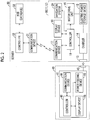
- FIG. 1 is a configuration diagram of a system 1 to which a vehicle 10 according to this embodiment is applied.
- the system 1 includes the plurality of vehicles 10 and a server 30.
- the plurality of vehicles 10 are vehicles of the same type.
- the plurality of vehicles 10 has equivalent specifications.
- the vehicle 10 is a connected vehicle that is continuously connected to a network during actuation of a vehicle system.
- the vehicle 10 is also an electric vehicle (EV) that includes a motor as a drive power source.
- EV electric vehicle
- the vehicle 10 can perform external charging in which an in-vehicle electric power storage device stores electric power supplied from a charging stand 40.
- the vehicle 10 is configured to send identification (ID) that is allocated to each of the vehicles 10 and record data (for example, global positioning system (GPS) data and SOC data of the in-vehicle electric power storage device) indicative of a travel record to the server 30 in specified cycles.
- ID identification
- the specified cycle is a predetermined time interval and is a time interval of 15 seconds or 30 seconds, for example.
- a certain vehicle of the plurality of vehicles 10 will also be referred to as a "host vehicle 11"
- the vehicles 10 other than the host vehicle 11 will also be referred to as "other vehicles 12" as a matter of convenience.
- the server 30 is configured to receive the ID and the record data from each of the vehicles 10 in specified cycles.
- a database that manages a transition of the SOC per vehicle is constructed by aggregating the record data of each of the vehicles 10. This database manages the transition of the SOC of each of the vehicles 10 that start traveling from the charging stand 40, and manages the transition of the SOC per starting point (the charging stand 40). Note that the charging stands 40 are installed throughout a country. A detailed description on the database will be made below.
- the vehicle 10 performs the external charging by using the charging stand 40.
- a predicted transition result of the SOC in future travel of the vehicle 10 is sent from the server 30 to the vehicle 10 in response to a request from the vehicle 10.
- a target value of the SOC hereinafter also referred to as a "target SOC" in the external charging is decided.
- FIG. 2 is a further detailed diagram of configurations of the vehicle 10, the server 30, and the charging stand 40.
- the vehicle 10 includes an inlet 13, a charger 14, an electric power storage device 15, a motor drive unit 16, a communication device 17, a display device 18, a navigation system 29, and a controller 19.
- the server 30 includes a communication device 31, a controller 32, and a hard disk drive (HDD) 33.
- the charging stand 40 includes a power feeding facility 41 and a connector 42.
- the connector 42 is configured to be connectable to the inlet 13 of the vehicle 10.
- the electric power supplied from the power feeding facility 41 is supplied to the vehicle 10 via the connector 42.
- the power feeding facility 41 includes a power feeding device 49, a communication device 44, a display device 46, and a controller 48.
- the power feeding device 49 is configured to supply the electric power to the vehicle 10 by using the electric power supplied from a system power supply, for example.
- the communication device 44 is configured to be wirelessly communicable with the server 30 (the communication device 31), for example.
- the display device 46 is a display device that is configured to display information on the external charging.
- the controller 48 includes a CPU and memory, which are not shown, therein and controls equipment (the communication device 44, the display device 46, the power feeding device 49, and the like) of the charging stand 40 on the basis of information stored in the memory and information from each sensor.
- the communication device 31 is configured to be wirelessly communicable with the vehicle 10 (the communication device 17) and the charging stand 40 (the communication device 44), for example.
- the communication device 31 is connected to the controller 32 by a communication line, sends information that is transmitted from the controller 32 to the vehicle 10, and transmits information that is received from the vehicle 10 to the controller 32.
- the communication device 31 receives the record data (for example, the GPS data and the SOC data) indicative of the travel record and the ID of each of the vehicles 10 from each of the vehicles 10 in the specified cycles, for example.
- the controller 32 includes a central processing unit (CPU) and memory, which are not shown, therein and is configured to control equipment (the communication device 31, the HDD 33, and the like) of the server 30 in accordance with a control program stored in the memory.
- CPU central processing unit
- memory which are not shown, therein and is configured to control equipment (the communication device 31, the HDD 33, and the like) of the server 30 in accordance with a control program stored in the memory.
- the HDD 33 is a storage device that stores various types of data.
- the HDD 33 stores the record data (for example, the GPS data and the SOC data), which is received from each of the vehicles 10 in the specified cycles, in association with the ID of each of the vehicles 10.
- the HDD 33 also stores the above-described database (the database that manages the transition of the SOC of each of the vehicles 10 per starting point (the charging stand 40)).
- FIG. 3 is a table that shows one example of a database 50 stored in the HDD 33.
- the database 50 manages the SOC data (for example, S10 to S42) of the vehicles 10 (for example, vehicles X1 to X4) by a travel distance from the starting point (for example, D00 to D13) in association with the starting point (for example, charging stands A1 to A4).
- An interval of the travel distance, at which the SOC data is managed, is a specified interval. As the specified interval, any of intervals from several tens of meters to several kilometers is adopted, for example.
- the controller 32 extracts the SOC data at a time point at which the vehicle X1 leaves the charging stand A1 from the record data of the vehicle X1 that is stored in the HDD 33. More specifically, of the record data of the vehicle XI, the controller 32 extracts the SOC data that is associated with the GPS data indicative of the vicinity of the charging stand A1 (within several meters to several tens of meters in radius, for example). The controller 32 also extracts the SOC data from the record data of the vehicle X1 that is stored in the HDD 33 every time the vehicle X1 (the vehicle 10) advances for the specified interval after leaving the charging stand A1 (the charging stand 40).
- the SOC data is the SOC data at a point at which the vehicle X1 has advanced for the specified interval is determined by referring to the GPS data that is associated with the SOC data.
- the controller 32 extracts the SOC data every time each of the vehicles 10 that leaves the charging stand advances for the specified interval. In this way, the database 50 ( FIG. 3 ) is generated.
- the inlet 13 is configured to be connectable to the connector 42 of the power feeding facility 41 that is provided in the charging stand 40.
- the charger 14 is provided between the inlet 13 and the electric power storage device 15, converts the electric power received from the charging stand 40 to the electric power storable in the electric power storage device 15, and outputs the converted electric power to the electric power storage device 15.
- the electric power storage device 15 is an electric power storing element that is configured to be chargeable and dischargeable.
- the electric power storage device 15 is configured by including a secondary battery such as a lithium-ion battery, a nickel-metal hydride battery, or a lead-acid battery and a power storage element such as an electric double-layered capacitor.
- the motor drive unit 16 is electrically connected to the electric power storage device 15.
- the motor drive unit 16 generates vehicle drive power by using the electric power that is supplied from the electric power storage device 15.
- the motor drive unit 16 includes: a motor generator that is mechanically connected (coupled) to drive wheels; and a power control unit (an inverter and the like) that controls an energization amount of the motor generator. Output of the motor drive unit 16 (the energization amount of the motor generator) is controlled by a control signal from the controller 19.
- the communication device 17 is configured to be wirelessly communicable with the server 30 (the communication device 31), for example.
- the communication device 17 is connected to the controller 19 by a communication line, sends information that is transmitted from the controller 19 to the server 30, and transmits information that is received from the server 30 to the controller 19.
- the communication device 17 sends the record data and the ID of the corresponding vehicle 10 to the server 30 in the specified cycles.
- the display device 18 is a display device that is configured to display information on the external charging and the like.
- the navigation system 29 is a system that guides a user through a route to a destination.
- internal memory (not shown) stores map information, for example.
- the navigation system 29 displays a current location of the vehicle 10 on a map by using information indicative of the current location of the vehicle 10, which is acquired by using the GPS, and the map information.
- the controller 19 includes a CPU and memory, which are not shown, therein and controls equipment (the charger 14, the motor drive unit 16, the communication device 17, the display device 18, the navigation system 29, and the like) of the vehicle 10 on the basis of information stored in the memory and information from each sensor. Note that a configuration including the controller 19 and the communication device 17 is one example of the "charging control apparatus".
- the controller 19 is configured to compute the SOC of the electric power storage device 15 by using an integrated value of output of a current sensor (not shown) that detects a current of the electric power storage device 15, for example.
- the controller 19 stores data indicative of an upper limit value and a lower limit value of the SOC as well as the target SOC in the external charging in the internal memory.
- the controller 19 controls the charger 14 such that the external charging continues until the SOC of the electric power storage device 15 reaches the target SOC.
- the target SOC is set to a first target SOC (for example, 80%) by default.
- the controller 19 changes the target SOC in accordance with a situation. Next, a detailed description will be made on a decision method of the target SOC in the external charging.
- the motor generator that is provided in the motor drive unit 16 is configured to perform regenerative power generation during deceleration of the vehicle 10, during a reduction in acceleration of the vehicle 10 on a downhill road, and the like, for example.
- Regenerative electric power that is generated by the regenerative power generation is stored in the electric power storage device 15.
- the electric power storage device 15 can no longer store the regenerative electric power even when the regenerative electric power is generated.
- the regenerative electric power that is generated at a time when the vehicle travels down the mountain may not sufficiently be stored in the electric power storage device 15. In such a case, some of the regenerative electric power is possibly wasted.
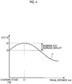
- FIG. 4 is a chart that illustrates an example in which the SOC exceeds the SOC after completion of the external charging due to travel of the vehicle 10 after the completion of the external charging.
- a horizontal axis represents the travel distance of the vehicle 10, and a vertical axis represents the SOC of the electric power storage device 15.
- a travel distance D0 point (0 km) is the installation location of the charging stand 40.
- the external charging is supposedly performed by using the charging stand 40 until the SOC of the electric power storage device 15 reaches S1 (the target SOC).
- a route from the D0 point to a D1 point is a downhill road.
- the regenerative electric power is generated from the D0 point to the D1 point by the reduction in the acceleration of the vehicle 10 and the like, and the SOC of the electric power storage device 15 is increased from S1 to S2, for example.
- an uphill road or a flat road mainly continues, and the SOC of the electric power storage device 15 is gradually reduced from S2.
- an increase amount of the SOC (hereinafter also simply referred to as an "SOC increase amount”) that is compared to the SOC upon the completion of the external charging (at the travel distance D0 point) becomes the maximum at the travel distance D1 point.
- a maximum value of the SOC increase amount will also be referred to as a "maximum SOC increase amount”.
- the regenerative electric power that is generated in a period from a time point at which the SOC reaches the upper limit value to a time point at which the SOC starts being reduced is not stored in the electric power storage device 15 and thus is wasted.
- the controller 19 lowers the target SOC from the first target SOC to a second target SOC (the second target SOC ⁇ the first target SOC).
- the specified amount is, for example, the upper limit value of the SOC - the target SOC (the first target SOC).
- the controller 19 determines whether the maximum SOC increase amount is equal to or larger than the specified amount and thereby predicts whether the SOC exceeds the target SOC (the first target SOC) by the specified amount or larger in the section when the host vehicle 11 starts traveling after the completion of the external charging. That is, when the maximum SOC increase amount is equal to or larger than the specified amount, it is predicted that the SOC exceeds the first target SOC by the specified amount or larger in the section by the future travel of the host vehicle 11.
- the second target SOC is a value that is obtained by subtracting (the maximum SOC increase amount - the specified amount) or a value that exceeds (the maximum SOC increase amount - the specified amount) from the first target SOC. In this way, it is possible to reduce such a possibility that the SOC of the electric power storage device 15 exceeds the upper limit value due to the travel of the vehicle 10 after the completion of the external charging.
- the host vehicle 11 sends data (the GPS data) indicative of the current location (the location of the charging stand) to the server 30.
- the controller 32 of the server 30 searches the charging stand 40 that corresponds to the received GPS data (for example, the charging stand A1 ( FIG. 3 )) on the database 50 ( FIG. 3 ). For example, the controller 32 searches the charging stand 40 that exists within several meters to several tens of meters in radius from the point indicated by the received GPS data.
- the controller 32 extracts the SOC data of the other vehicle(s) 12 that is associated with the charging stand A1. For example, the controller 32 extracts the SOC data at each of the travel distances up to a specified travel distance (for example, D13 ( FIG. 3 )). In the case where the data of the plurality of other vehicles 12 is found, the controller 32 computes an average value of a plurality of types of the SOC data (hereinafter also referred to as "average SOC data") per travel distance. There is a case where an initial value (the SOC at the time point of leaving the charging stand 40) differs in each of the types of the data of the plurality of other vehicles 12. However, the average value of the SOC data of the plurality of other vehicles 12 represents an average change amount of the SOC in the plurality of other vehicles 12 (how much the SOC is increased by the future travel of the host vehicle 11 and the like).
- the controller 32 predicts the transition of the SOC (for example, a transition L1 of the SOC ( FIG. 4 )) by executing known interpolation processing, for example, on the basis of the computed average SOC data per travel distance.
- the server 30 sends data indicative of the predicted transition of the SOC to the host vehicle 11.
- the controller 19 extracts the maximum value of the SOC (for example, S2 ( FIG. 4 )) and the initial value of the SOC (for example, S1 ( FIG. 4 )) in the future transition of the SOC and subtracts the initial value of the SOC from the maximum value of the SOC, so as to compute the maximum SOC increase amount.
- the controller 19 lowers the target SOC from the first target SOC to the second target SOC.
- FIG. 5 is a flowchart of a procedure of target SOC decision processing.
- the processing shown in the flowchart on the left is executed by the host vehicle 11.
- the processing shown in the flowchart on the right is executed by the server 30.
- the processing shown by these flowcharts is executed after the connector 42 is connected to the inlet 13 for the external charging, for example.
- the controller 19 acquires the GPS data from the navigation system 29 and controls the communication device 17 to send a data request for requesting the predicted data on the transition of the SOC in the future travel and the acquired GPS data to the server 30 (step S100).
- the controller 32 refers to the database 50 ( FIG. 3 ) so as to extract the SOC data per travel distance of each of the other vehicles 12 that have left the charging stand near a stop location of the host vehicle 11 (the location indicated by the received GPS data) (the data on the transition of the SOC in each of the other vehicles 12) (step (S110).
- the controller 32 computes the average SOC data per travel distance, for example, on the basis of the extracted SOC data and predicts the transition of the SOC on the basis of the computed average SOC data per travel distance (step S120).
- the controller 32 controls the communication device 31 so as to send the data indicative of the predicted transition of the SOC to the host vehicle 11 (step S130).
- the controller 19 monitors whether the predicted data on the transition of the SOC has been received. Once reception of the predicted data on the transition of the SOC from the server 30 is confirmed, the controller 19 computes the maximum SOC increase amount on the basis of the predicted data on the transition of the SOC that has been received (step S140).
- the controller 19 determines whether the computed maximum SOC increase amount is equal to or larger than a difference between the upper limit value of the SOC and the target SOC (the first target SOC) (the specified amount) (step S150). If it is determined that the maximum SOC increase amount is equal to or larger than the difference between the upper limit value of the SOC and the target SOC (YES in step S150), the controller 19 lowers the target SOC from the first target SOC to the second target SOC (step S160). Thereafter, the controller 19 executes the processing for the external charging in accordance with the second target SOC (step S170).
- step S150 the controller 19 executes the processing for the external charging in accordance with the first target SOC (in a state of maintaining the target SOC to the first target SOC) (step S170).
- the controller 19 lowers the target SOC from the first target SOC to the second target SOC.
- the target SOC in the external charging is lowered from the first target SOC to the second target SOC.
- attention is focused on such a point that, due to lowering of the target SOC to the second target SOC, the SOC of the electric power storage device 15 possibly reaches a lower limit value before a sufficient amount of the regenerative electric power is collected.
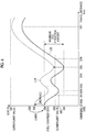
- FIG. 6 is a chart that illustrates an example in which the SOC of the electric power storage device 15 reaches the lower limit value before the sufficient amount of the regenerative electric power is collected.
- a horizontal axis represents the travel distance of the vehicle 10, and a vertical axis represents the SOC of the electric power storage device 15.
- a transition L20 of the SOC represents a prediction result of the transition of the SOC in the future travel of the host vehicle 11 after the target SOC is lowered from S06 (the first target SOC) to S04 (the second target SOC).
- Data indicative of the transition L20 of the SOC is computed by changing the entire data indicative of the transition of the SOC that is received from the server 30 (the predicted data based on the record data of the plurality of other vehicles 12) in accordance with a change in the initial value (the target SOC), for example.
- the target SOC falls below the upper limit value (S07) at a travel distance D07 point at which the SOC becomes the maximum.
- the SOC falls below the lower limit value (S03) in a section between the travel distances D01 and D03 and a section between the travel distances D04 and D06.
- the electric power that lacks in the section from D01 to D03 is the electric power that corresponds to S03 - S02 (hereinafter also referred to as "first lacking electric power”
- the electric power that lacks in the section from D04 to D06 is the electric power that corresponds to S03 - S01 (hereinafter also referred to as "second lacking electric power”).
- the second lacking electric power is greater than the first lacking electric power.
- the vehicle 10 is the EV. Accordingly, when the SOC of the electric power storage device 15 reaches the lower limit value, it becomes difficult for the vehicle 10 to continue the travel.
- the controller 19 increases the target SOC from the second target SOC in accordance with an amount of the lacking electric power.
- the controller 19 increases the target SOC from the second target SOC in accordance with the amount of the lacking electric power in the section where the amount of the lacking electric power is the largest.
- the controller 19 increases the target SOC from S04 (the second target SOC) to S05 in accordance with the amount of the second lacking electric power in the section between the travel distances D04 and D06 (the section where the amount of the lacking electric power is the largest).
- the future transition of the SOC in the vehicle 10 is represented by L10.
- the electric power never becomes insufficient in any of the sections of the future travel route of the vehicle 10.
- FIG. 7 is a flowchart of a procedure of the target SOC decision processing in this modified example.
- the processing shown in the flowchart on the left is executed by the host vehicle 11.
- the processing shown in the flowchart on the right is executed by the server 30.
- the processing shown by these flowcharts is executed after the connector 42 is connected to the inlet 13 for the external charging, for example. Because the processing shown in steps S200 to S260 and S290 are respectively the same as the processing shown in steps S100 to S160 and S170 in FIG. 5 , the description thereon will not be made.
- the controller 19 determines whether a section where the SOC falls below the lower limit value (a section where the electric power becomes insufficient) will be present when the host vehicle 11 starts traveling after the completion of the external charging in accordance with the second target SOC (step S270).
- the controller 19 extracts the minimum value of the SOC (for example, S01 ( FIG. 6 )) and the initial value of the SOC (for example, S04 ( FIG. 6 )) in the future transition of the SOC, and subtracts the minimum value of the SOC from the initial value of the SOC to compute a maximum SOC reduction amount. Then, if the maximum SOC reduction amount is larger than a value that is obtained by subtracting the lower limit value of the SOC (for example, S03 ( FIG.
- the controller 19 determines that the section where the SOC falls below the lower limit value (the section where the electric power becomes insufficient) will be present when the host vehicle 11 starts traveling after the completion of the external charging in accordance with the second target SOC.
- the controller 19 increases the target SOC such that the electric power does not become insufficient in the section where the amount of the lacking electric power is the largest (step S280). For example, the controller 19 increases the target SOC by adding the lacking electric power (for example, S03 - S01 in FIG. 6 ) or the larger value than the lacking electric power to the second target SOC. Thereafter, the controller 19 executes the processing for the external charging in accordance with the increased target SOC (step S290).
- step S270 determines that the section where the SOC falls below the lower limit value will not be present.
- the controller 19 executes the processing for the external charging in accordance with the second target SOC (in a state of maintaining the target SOC to the second target SOC) (step S290).
- the controller 19 increases the target SOC from the second target SOC in accordance with the amount of the lacking electric power. Accordingly, according to the vehicle 10, the target value of the SOC in the external charging can be decided such that the electric power does not become insufficient on the future travel route of the vehicle 10.
- the target SOC decision processing for the external charging is executed in the vehicle 10.
- the target SOC decision processing does not always have to be executed in the vehicle 10.
- the target SOC decision processing may be executed in the charging stand 40.
- the processing that is executed by the controller 19 of the host vehicle 11 is executed by the controller 48 of the charging stand 40, for example.
- all of the processing executed by the controller 19 does not always have to be executed by the controller 48.
- the controller 48 only has to execute processing to change the target SOC at least in the case where it is predicted that the SOC exceeds the target SOC by the specified amount or larger in the section when the host vehicle 11 starts traveling after the completion of the external charging.
- the communication device 44 communicates with the communication device 31 of the server 30. That is, in the above embodiment, the "charging control apparatus" is mounted on the vehicle 10. However, the “charging control apparatus” may be mounted on the charging stand 40.
- the vehicle 10 is the electric vehicle.
- the vehicle 10 does not always have to be the electric vehicle and may be a plug-in hybrid vehicle (PHV), for example.
- PGV plug-in hybrid vehicle
- the vehicle 10 only has to be chargeable externally and be able to generate the regenerative power.
- the vehicle 10 is continuously connected to the network.
- the vehicle 10 does not always have to be connected to the network.
- the vehicle 10 only has to be communicable with the server 30 when necessary, for example.
- the target SOC is lowered from the first target SOC to the second target SOC. That is, when it is predicted that the SOC exceeds the upper limit value due to the future travel of the host vehicle 11, the target SOC is lowered.
- the controller 19 may lower the target SOC even when it is not necessarily predicted that the SOC exceeds the upper limit value.
- the controller 19 may lower the target SOC in the case where the maximum SOC increase amount is equal to or larger than a value (> 0) that is smaller than the value of (the upper limit value of the SOC - target SOC).
- the server 30 predicts the transition of the SOC that is occurred by the travel of the host vehicle 11 after the external charging.
- the server 30 does not always have to predict the transition of the SOC.
- the transition of the SOC may be predicted in the vehicle 10.
- the SOC data per travel distance of each of the plurality of other vehicles 12 is sent from the server 30 to the host vehicle 11, the plurality of other vehicles 12 having left the charging stand 40 that the host vehicle 11 is about to use. Then, the transition of the SOC is predicted in the host vehicle 11 on the basis of the received data.
- the SOC data of each of the other vehicles 12 in order to predict the transition of the SOC that is occurred by the travel of the host vehicle 11 after the external charging, only the SOC data of each of the other vehicles 12 is used, the other vehicles 12 having started traveling from the charging stand 40 that the host vehicle 11 is about to use.
- the data that is used to predict the transition of the SOC is not limited to the SOC data of the other vehicles 12.
- the SOC data of the host vehicle 11 may be used to predict the transition of the SOC.
- the controller 19 lowers the target SOC from the first target SOC to the second target SOC.
- the controller 19 does not always have to lower the target SOC.
- the controller 19 may check with the user whether to lower the target SOC. More specifically, in the case where the maximum SOC increase amount is equal to or larger than the specified amount, the controller 19 causes the display device 18 to display a screen for checking with the user whether to lower the target SOC.
- the controller 19 When the user selects an option to permit lowering of the target SOC, the controller 19 lowers the target SOC. On the other hand, when the user selects an option to disallow lowering of the target SOC, the controller 19 does not lower the target SOC. In this way, the user's intention can be reflected to the decision on the target SOC.
Landscapes
- Engineering & Computer Science (AREA)
- Transportation (AREA)
- Mechanical Engineering (AREA)
- Automation & Control Theory (AREA)
- Power Engineering (AREA)
- Life Sciences & Earth Sciences (AREA)
- Sustainable Development (AREA)
- Sustainable Energy (AREA)
- Human Computer Interaction (AREA)
- Electric Propulsion And Braking For Vehicles (AREA)
- Charge And Discharge Circuits For Batteries Or The Like (AREA)
- Traffic Control Systems (AREA)
Abstract
Description
- The present disclosure relates to a charging control apparatus for a vehicle and a charging control method for the same, in which the vehicle is capable of storing electric power in an in-vehicle electric power storage device and the electric power is supplied from an electric power supply on the outside of a vehicle (hereinafter also referred to as "external charging").
- An information communication system that includes an in-vehicle device mounted on a vehicle and a center device is disclosed in Japanese Patent Application Publication No.
2012-181183 JP 2012-181183 A - In
JP 2012-181183 A - The vehicle includes a motor generator and an electric power storage device. The motor generator performs regenerative power generation during deceleration and the like of the vehicle, and the electric power generated by the regenerative power generation (hereinafter also referred to as "regenerative electric power") is stored in the electric power storage device. In a technique disclosed in
JP 2012-181183 A - Accordingly, in the case where the external charging is performed at a charging stand on top of a mountain, for example, in accordance with the required electric power amount from the current location to the destination, the electric power storage device is charged until the SOC thereof reaches a value near an upper limit value. In such a case, the regenerative electric power that is generated at a time when the vehicle travels down the mountain may not sufficiently be stored in the electric power storage device, and some of the regenerative electric power is wasted.
- The present disclosure provides a charging control apparatus and a charging control method capable of reducing a possibility of wasting regenerative electric power of a vehicle.
- A first aspect of the present disclosure is a charging control apparatus for a vehicle. The vehicle includes a motor generator and an electric power storage device. The motor generator is configured to be coupled to drive wheels. The electric power storage device is electrically connected to the motor generator. The charging control apparatus includes a communication device and a controller. The communication device is configured to receive data from a server that aggregates record data indicative of a travel record of each of the vehicles. The controller is configured to execute processing for external charging that is charging of the electric power storage device by electric power supplied from a power supply on the outside of the vehicle. The controller is configured to execute the external charging in accordance with a target value of State of Charge (SOC) of the electric power storage device. The controller is configured to lower the target value from a first target value to a second target value in a case where the controller predicts that the SOC exceeds the target value by a specified amount or larger in a section, in accordance with the record data that is aggregated in the server, when the vehicle starts traveling after completion of the external charging.
- According to the above configuration, in the case where it is predicted that the SOC exceeds the target value by the specified amount or larger in the section when the vehicle starts traveling after the completion of the external charging, the target value in the external charging is lowered from the first target value to the second target value. Thus, according to this charging control apparatus, upon the completion of the external charging, a large room is secured until the SOC reaches an upper limit value in accordance with a situation. Therefore, a possibility of regenerative electric power being wasted can be reduced.
- In the vehicle, the controller may be configured to increase the target value from the second target value in accordance with an amount of lacking electric power in a case where the controller predicts that the SOC reaches a lower limit value and the electric power becomes insufficient in the section, in accordance with the record data that is aggregated in the server, when the vehicle starts traveling after the completion of the external charging in accordance with the second target value.
- According to the above configuration, in the case where it is predicted that the SOC reaches the lower limit value and the electric power becomes insufficient in the section when the vehicle starts traveling after the completion of the external charging in accordance with the second target value, the target value of the SOC is increased from the second target value in accordance with the amount of the lacking electric power. Thus, according to this charging control apparatus, the target value of the SOC in the external charging can be decided in a manner to prevent insufficiency of the electric power on a future travel route of the vehicle.
- In the charging control apparatus, the controller may be configured to increase the target value in the external charging from the second target value in accordance with the amount of the lacking electric power in a section where the amount of the lacking electric power is the largest in a case where the controller predicts that the SOC reaches the lower limit value and the electric power becomes insufficient in the plurality of sections, in accordance with the record data that is aggregated in the server, when the vehicle starts traveling after the completion of the external charging in accordance with the second target value.
- According to the above configuration, in the case where it is predicted that the SOC reaches the lower limit value and the electric power becomes insufficient in the plurality of sections when the vehicle starts traveling after the completion of the external charging in accordance with the second target value, the target value of the SOC is increased from the second target value in accordance with the amount of the lacking electric power in the section where the amount of the lacking electric power is the largest. Thus, according to this charging control apparatus, the target value of the SOC in the external charging can be decided in a manner to prevent the insufficiency of the electric power in any of the sections of the future travel route of the vehicle.
- A second aspect of the present disclosure is a charging control method for a vehicle. The vehicle includes a motor generator, an electric power storage device, and a charging control apparatus. The motor generator is coupled to drive wheels. The electric power storage device is electrically connected to the motor generator. The charging control apparatus includes a communication device and a controller. The communication device is configured to receive data from a server that aggregates record data indicative of a travel record of each of the vehicles. The controller is configured to execute processing for external charging that is charging of the electric power storage device by electric power supplied from a power supply on the outside of the vehicle. The charging control method including: executing, by the controller, the external charging in accordance with a target value of State of Charge (SOC) of the electric power storage device; and lowering, by the controller, the target value from a first target value to a second target value by the controller in a case where the controller predicts that the SOC exceeds the target value by a specified amount or larger in a section in accordance with the record data that is aggregated in the server when the vehicle starts traveling after completion of the external charging.
- The present disclosure can provide the charging control apparatus and the charging control method capable of reducing the possibility of the regenerative electric power in the vehicle being wasted.
- Features, advantages, and technical and industrial significance of exemplary embodiments of the invention will be described below with reference to the accompanying drawings, in which like numerals denote like elements, and wherein:
-
FIG. 1 is a system configuration diagram; -
FIG. 2 is a detailed diagram of configurations of a vehicle, a charging stand, and a server; -
FIG. 3 is a table that shows one example of a database stored in an HDD; -
FIG. 4 is a chart that illustrates an example in which an SOC exceeds the SOC after completion of external charging due to travel of the vehicle after the completion of the external charging; -
FIG. 5 is a flowchart of a procedure of target SOC decision processing; -
FIG. 6 is a chart that illustrates an example in which the SOC of an electric power storage device reaches a lower limit value before a sufficient amount of regenerative electric power is collected; and -
FIG. 7 is a flowchart of a procedure of the target SOC decision processing in a modified example. - A detailed description will hereinafter be made on an embodiment with reference to the drawings. Note that the same or corresponding portions in the drawings are denoted by the same reference numerals and the description thereon will not be repeated.
-
FIG. 1 is a configuration diagram of asystem 1 to which avehicle 10 according to this embodiment is applied. Referring toFIG. 1 , thesystem 1 includes the plurality ofvehicles 10 and aserver 30. Note that, in this embodiment, the plurality ofvehicles 10 are vehicles of the same type. Thus, the plurality ofvehicles 10 has equivalent specifications. - The
vehicle 10 is a connected vehicle that is continuously connected to a network during actuation of a vehicle system. Thevehicle 10 is also an electric vehicle (EV) that includes a motor as a drive power source. Thevehicle 10 can perform external charging in which an in-vehicle electric power storage device stores electric power supplied from a chargingstand 40. - The
vehicle 10 is configured to send identification (ID) that is allocated to each of thevehicles 10 and record data (for example, global positioning system (GPS) data and SOC data of the in-vehicle electric power storage device) indicative of a travel record to theserver 30 in specified cycles. The specified cycle is a predetermined time interval and is a time interval of 15 seconds or 30 seconds, for example. Hereinafter, a certain vehicle of the plurality ofvehicles 10 will also be referred to as a "host vehicle 11", and thevehicles 10 other than thehost vehicle 11 will also be referred to as "other vehicles 12" as a matter of convenience. - The
server 30 is configured to receive the ID and the record data from each of thevehicles 10 in specified cycles. In theserver 30, a database that manages a transition of the SOC per vehicle is constructed by aggregating the record data of each of thevehicles 10. This database manages the transition of the SOC of each of thevehicles 10 that start traveling from the chargingstand 40, and manages the transition of the SOC per starting point (the charging stand 40). Note that the charging stands 40 are installed throughout a country. A detailed description on the database will be made below. - For example, the
vehicle 10 performs the external charging by using the chargingstand 40. In this case, before the external charging is started, a predicted transition result of the SOC in future travel of thevehicle 10 is sent from theserver 30 to thevehicle 10 in response to a request from thevehicle 10. In thevehicle 10, by referring to the received prediction result, a target value of the SOC (hereinafter also referred to as a "target SOC") in the external charging is decided. A detailed description thereon will be made below. - Detailed Configurations of Vehicle (EV), Server, and Charging Stand
FIG. 2 is a further detailed diagram of configurations of thevehicle 10, theserver 30, and the chargingstand 40. Referring toFIG. 2 , thevehicle 10 includes aninlet 13, acharger 14, an electricpower storage device 15, amotor drive unit 16, acommunication device 17, adisplay device 18, anavigation system 29, and acontroller 19. Theserver 30 includes acommunication device 31, acontroller 32, and a hard disk drive (HDD) 33. The chargingstand 40 includes apower feeding facility 41 and aconnector 42. - First, the configuration of the charging
stand 40 will be described. Theconnector 42 is configured to be connectable to theinlet 13 of thevehicle 10. The electric power supplied from thepower feeding facility 41 is supplied to thevehicle 10 via theconnector 42. Thepower feeding facility 41 includes apower feeding device 49, acommunication device 44, adisplay device 46, and acontroller 48. Thepower feeding device 49 is configured to supply the electric power to thevehicle 10 by using the electric power supplied from a system power supply, for example. - The
communication device 44 is configured to be wirelessly communicable with the server 30 (the communication device 31), for example. Thedisplay device 46 is a display device that is configured to display information on the external charging. Thecontroller 48 includes a CPU and memory, which are not shown, therein and controls equipment (thecommunication device 44, thedisplay device 46, thepower feeding device 49, and the like) of the chargingstand 40 on the basis of information stored in the memory and information from each sensor. - Next, the configuration of the
server 30 will be described. Thecommunication device 31 is configured to be wirelessly communicable with the vehicle 10 (the communication device 17) and the charging stand 40 (the communication device 44), for example. Thecommunication device 31 is connected to thecontroller 32 by a communication line, sends information that is transmitted from thecontroller 32 to thevehicle 10, and transmits information that is received from thevehicle 10 to thecontroller 32. As described above, thecommunication device 31 receives the record data (for example, the GPS data and the SOC data) indicative of the travel record and the ID of each of thevehicles 10 from each of thevehicles 10 in the specified cycles, for example. - The
controller 32 includes a central processing unit (CPU) and memory, which are not shown, therein and is configured to control equipment (thecommunication device 31, theHDD 33, and the like) of theserver 30 in accordance with a control program stored in the memory. - The
HDD 33 is a storage device that stores various types of data. TheHDD 33 stores the record data (for example, the GPS data and the SOC data), which is received from each of thevehicles 10 in the specified cycles, in association with the ID of each of thevehicles 10. TheHDD 33 also stores the above-described database (the database that manages the transition of the SOC of each of thevehicles 10 per starting point (the charging stand 40)). -
FIG. 3 is a table that shows one example of adatabase 50 stored in theHDD 33. Referring toFIG. 3 , thedatabase 50 manages the SOC data (for example, S10 to S42) of the vehicles 10 (for example, vehicles X1 to X4) by a travel distance from the starting point (for example, D00 to D13) in association with the starting point (for example, charging stands A1 to A4). An interval of the travel distance, at which the SOC data is managed, is a specified interval. As the specified interval, any of intervals from several tens of meters to several kilometers is adopted, for example. - Next, a description will be made on a generation method of the
database 50. For example, thecontroller 32 extracts the SOC data at a time point at which the vehicle X1 leaves the charging stand A1 from the record data of the vehicle X1 that is stored in theHDD 33. More specifically, of the record data of the vehicle XI, thecontroller 32 extracts the SOC data that is associated with the GPS data indicative of the vicinity of the charging stand A1 (within several meters to several tens of meters in radius, for example). Thecontroller 32 also extracts the SOC data from the record data of the vehicle X1 that is stored in theHDD 33 every time the vehicle X1 (the vehicle 10) advances for the specified interval after leaving the charging stand A1 (the charging stand 40). Note that whether the SOC data is the SOC data at a point at which the vehicle X1 has advanced for the specified interval is determined by referring to the GPS data that is associated with the SOC data. In a similar method, thecontroller 32 extracts the SOC data every time each of thevehicles 10 that leaves the charging stand advances for the specified interval. In this way, the database 50 (FIG. 3 ) is generated. - Referring again to
FIG. 2 , the configuration of thevehicle 10 will next be described. Theinlet 13 is configured to be connectable to theconnector 42 of thepower feeding facility 41 that is provided in the chargingstand 40. Thecharger 14 is provided between theinlet 13 and the electricpower storage device 15, converts the electric power received from the chargingstand 40 to the electric power storable in the electricpower storage device 15, and outputs the converted electric power to the electricpower storage device 15. - The electric
power storage device 15 is an electric power storing element that is configured to be chargeable and dischargeable. The electricpower storage device 15 is configured by including a secondary battery such as a lithium-ion battery, a nickel-metal hydride battery, or a lead-acid battery and a power storage element such as an electric double-layered capacitor. - The
motor drive unit 16 is electrically connected to the electricpower storage device 15. Themotor drive unit 16 generates vehicle drive power by using the electric power that is supplied from the electricpower storage device 15. Themotor drive unit 16 includes: a motor generator that is mechanically connected (coupled) to drive wheels; and a power control unit (an inverter and the like) that controls an energization amount of the motor generator. Output of the motor drive unit 16 (the energization amount of the motor generator) is controlled by a control signal from thecontroller 19. - The
communication device 17 is configured to be wirelessly communicable with the server 30 (the communication device 31), for example. Thecommunication device 17 is connected to thecontroller 19 by a communication line, sends information that is transmitted from thecontroller 19 to theserver 30, and transmits information that is received from theserver 30 to thecontroller 19. As described above, thecommunication device 17 sends the record data and the ID of the correspondingvehicle 10 to theserver 30 in the specified cycles. - The
display device 18 is a display device that is configured to display information on the external charging and the like. Thenavigation system 29 is a system that guides a user through a route to a destination. In thenavigation system 29, internal memory (not shown) stores map information, for example. Thenavigation system 29 displays a current location of thevehicle 10 on a map by using information indicative of the current location of thevehicle 10, which is acquired by using the GPS, and the map information. - The
controller 19 includes a CPU and memory, which are not shown, therein and controls equipment (thecharger 14, themotor drive unit 16, thecommunication device 17, thedisplay device 18, thenavigation system 29, and the like) of thevehicle 10 on the basis of information stored in the memory and information from each sensor. Note that a configuration including thecontroller 19 and thecommunication device 17 is one example of the "charging control apparatus". - The
controller 19 is configured to compute the SOC of the electricpower storage device 15 by using an integrated value of output of a current sensor (not shown) that detects a current of the electricpower storage device 15, for example. - In addition, the
controller 19 stores data indicative of an upper limit value and a lower limit value of the SOC as well as the target SOC in the external charging in the internal memory. Thecontroller 19 controls thecharger 14 such that the external charging continues until the SOC of the electricpower storage device 15 reaches the target SOC. Note that the target SOC is set to a first target SOC (for example, 80%) by default. Thecontroller 19 changes the target SOC in accordance with a situation. Next, a detailed description will be made on a decision method of the target SOC in the external charging. - The motor generator that is provided in the
motor drive unit 16 is configured to perform regenerative power generation during deceleration of thevehicle 10, during a reduction in acceleration of thevehicle 10 on a downhill road, and the like, for example. Regenerative electric power that is generated by the regenerative power generation is stored in the electricpower storage device 15. However, in the case where the SOC of the electricpower storage device 15 has reached the upper limit value, the electricpower storage device 15 can no longer store the regenerative electric power even when the regenerative electric power is generated. Accordingly, in the case where the external charging is performed at the chargingstand 40 installed on top of a mountain, for example, such that the SOC reaches a value near the upper limit value, the regenerative electric power that is generated at a time when the vehicle travels down the mountain may not sufficiently be stored in the electricpower storage device 15. In such a case, some of the regenerative electric power is possibly wasted. -
FIG. 4 is a chart that illustrates an example in which the SOC exceeds the SOC after completion of the external charging due to travel of thevehicle 10 after the completion of the external charging. A horizontal axis represents the travel distance of thevehicle 10, and a vertical axis represents the SOC of the electricpower storage device 15. - Referring to
FIG. 4 , a travel distance D0 point (0 km) is the installation location of the chargingstand 40. The external charging is supposedly performed by using the chargingstand 40 until the SOC of the electricpower storage device 15 reaches S1 (the target SOC). A route from the D0 point to a D1 point is a downhill road. In this case, the regenerative electric power is generated from the D0 point to the D1 point by the reduction in the acceleration of thevehicle 10 and the like, and the SOC of the electricpower storage device 15 is increased from S1 to S2, for example. Thereafter, an uphill road or a flat road mainly continues, and the SOC of the electricpower storage device 15 is gradually reduced from S2. - In the example shown in
FIG. 4 , an increase amount of the SOC (hereinafter also simply referred to as an "SOC increase amount") that is compared to the SOC upon the completion of the external charging (at the travel distance D0 point) becomes the maximum at the travel distance D1 point. Hereinafter, a maximum value of the SOC increase amount will also be referred to as a "maximum SOC increase amount". For example, in the case where the upper limit value of the SOC is positioned between S1 and S2, the regenerative electric power that is generated in a period from a time point at which the SOC reaches the upper limit value to a time point at which the SOC starts being reduced is not stored in the electricpower storage device 15 and thus is wasted. - For example, in the case where it is acknowledged in advance that the SOC is stuck to the upper limit value due to the travel of the
host vehicle 11 after the completion of the external charging, a possibility of the regenerative electric power being wasted can be reduced by lowering the target SOC (S1) in the external charging. - Accordingly, in the vehicle 10 (the host vehicle 11) according to this embodiment, in the case where it is predicted that the SOC exceeds the target SOC (the first target SOC) by a specified amount or larger in a section, in accordance with the record data (the record data of the other vehicles 12) that is aggregated in the
server 30, when thehost vehicle 11 starts traveling after the completion of the external charging, thecontroller 19 lowers the target SOC from the first target SOC to a second target SOC (the second target SOC < the first target SOC). - The specified amount is, for example, the upper limit value of the SOC - the target SOC (the first target SOC). In this embodiment, the
controller 19 determines whether the maximum SOC increase amount is equal to or larger than the specified amount and thereby predicts whether the SOC exceeds the target SOC (the first target SOC) by the specified amount or larger in the section when thehost vehicle 11 starts traveling after the completion of the external charging. That is, when the maximum SOC increase amount is equal to or larger than the specified amount, it is predicted that the SOC exceeds the first target SOC by the specified amount or larger in the section by the future travel of thehost vehicle 11. - According to the
vehicle 10, upon the completion of the external charging, a large room is secured until the SOC reaches the upper limit value in accordance with the situation. Thus, the possibility of the regenerative electric power being wasted can be reduced. - Note that the second target SOC is a value that is obtained by subtracting (the maximum SOC increase amount - the specified amount) or a value that exceeds (the maximum SOC increase amount - the specified amount) from the first target SOC. In this way, it is possible to reduce such a possibility that the SOC of the electric
power storage device 15 exceeds the upper limit value due to the travel of thevehicle 10 after the completion of the external charging. - Next, a description will be made on one example of a prediction method of the maximum SOC increase amount in the case where the
host vehicle 11 starts traveling after the completion of the external charging. First, thehost vehicle 11 sends data (the GPS data) indicative of the current location (the location of the charging stand) to theserver 30. Thecontroller 32 of theserver 30 searches the chargingstand 40 that corresponds to the received GPS data (for example, the charging stand A1 (FIG. 3 )) on the database 50 (FIG. 3 ). For example, thecontroller 32 searches the chargingstand 40 that exists within several meters to several tens of meters in radius from the point indicated by the received GPS data. - In the case where the charging stand A1 is found, the
controller 32 extracts the SOC data of the other vehicle(s) 12 that is associated with the charging stand A1. For example, thecontroller 32 extracts the SOC data at each of the travel distances up to a specified travel distance (for example, D13 (FIG. 3 )). In the case where the data of the plurality ofother vehicles 12 is found, thecontroller 32 computes an average value of a plurality of types of the SOC data (hereinafter also referred to as "average SOC data") per travel distance. There is a case where an initial value (the SOC at the time point of leaving the charging stand 40) differs in each of the types of the data of the plurality ofother vehicles 12. However, the average value of the SOC data of the plurality ofother vehicles 12 represents an average change amount of the SOC in the plurality of other vehicles 12 (how much the SOC is increased by the future travel of thehost vehicle 11 and the like). - The
controller 32 predicts the transition of the SOC (for example, a transition L1 of the SOC (FIG. 4 )) by executing known interpolation processing, for example, on the basis of the computed average SOC data per travel distance. Theserver 30 sends data indicative of the predicted transition of the SOC to thehost vehicle 11. By referring to the received data indicative of the transition of the SOC, thecontroller 19 extracts the maximum value of the SOC (for example, S2 (FIG. 4 )) and the initial value of the SOC (for example, S1 (FIG. 4 )) in the future transition of the SOC and subtracts the initial value of the SOC from the maximum value of the SOC, so as to compute the maximum SOC increase amount. - As described above, in the case where it is determined that the maximum SOC increase amount is equal to or larger than the specified amount (the upper limit value of the SOC - the target SOC (the first target SOC)), there is a high possibility that the SOC exceeds the upper limit value due to the future travel of the
vehicle 10. Accordingly, thecontroller 19 lowers the target SOC from the first target SOC to the second target SOC. -
FIG. 5 is a flowchart of a procedure of target SOC decision processing. The processing shown in the flowchart on the left is executed by thehost vehicle 11. The processing shown in the flowchart on the right is executed by theserver 30. The processing shown by these flowcharts is executed after theconnector 42 is connected to theinlet 13 for the external charging, for example. - Referring to
FIG. 5 , thecontroller 19 acquires the GPS data from thenavigation system 29 and controls thecommunication device 17 to send a data request for requesting the predicted data on the transition of the SOC in the future travel and the acquired GPS data to the server 30 (step S100). - When the
server 30 receives the data request from thehost vehicle 11 via thecommunication device 31, thecontroller 32 refers to the database 50 (FIG. 3 ) so as to extract the SOC data per travel distance of each of theother vehicles 12 that have left the charging stand near a stop location of the host vehicle 11 (the location indicated by the received GPS data) (the data on the transition of the SOC in each of the other vehicles 12) (step (S110). - The
controller 32 computes the average SOC data per travel distance, for example, on the basis of the extracted SOC data and predicts the transition of the SOC on the basis of the computed average SOC data per travel distance (step S120). Thecontroller 32 controls thecommunication device 31 so as to send the data indicative of the predicted transition of the SOC to the host vehicle 11 (step S130). - After sending the data request to the
server 30 in step S100, thecontroller 19 monitors whether the predicted data on the transition of the SOC has been received. Once reception of the predicted data on the transition of the SOC from theserver 30 is confirmed, thecontroller 19 computes the maximum SOC increase amount on the basis of the predicted data on the transition of the SOC that has been received (step S140). - Thereafter, the
controller 19 determines whether the computed maximum SOC increase amount is equal to or larger than a difference between the upper limit value of the SOC and the target SOC (the first target SOC) (the specified amount) (step S150). If it is determined that the maximum SOC increase amount is equal to or larger than the difference between the upper limit value of the SOC and the target SOC (YES in step S150), thecontroller 19 lowers the target SOC from the first target SOC to the second target SOC (step S160). Thereafter, thecontroller 19 executes the processing for the external charging in accordance with the second target SOC (step S170). - On the other hand, if it is determined that the maximum SOC increase amount is smaller than the difference between the upper limit value of the SOC and the target SOC (NO in step S150), the
controller 19 executes the processing for the external charging in accordance with the first target SOC (in a state of maintaining the target SOC to the first target SOC) (step S170). - As it has been described so far, in the
vehicle 10 according to this embodiment, in the case where it is predicted that the SOC exceeds the target SOC (the first target SOC) by the specified amount or larger in the section, in accordance with the record data that is aggregated in theserver 30, when thehost vehicle 11 starts traveling after the completion of the external charging, thecontroller 19 lowers the target SOC from the first target SOC to the second target SOC. Thus, according to thevehicle 10, upon the completion of the external charging, the large room is secured until the SOC reaches the upper limit value in accordance with the situation. Therefore, the possibility of the regenerative electric power being wasted can be reduced. - In the above embodiment, in order to avoid a situation where the regenerative electric power is wasted after the completion of the external charging, in the case where it is predicted that the maximum SOC increase amount in the future travel is equal to or larger than the specified amount, the target SOC in the external charging is lowered from the first target SOC to the second target SOC. In regard to the
vehicle 10 according to this modified example, attention is focused on such a point that, due to lowering of the target SOC to the second target SOC, the SOC of the electricpower storage device 15 possibly reaches a lower limit value before a sufficient amount of the regenerative electric power is collected. -
FIG. 6 is a chart that illustrates an example in which the SOC of the electricpower storage device 15 reaches the lower limit value before the sufficient amount of the regenerative electric power is collected. A horizontal axis represents the travel distance of thevehicle 10, and a vertical axis represents the SOC of the electricpower storage device 15. - Referring to
FIG. 6 , a transition L20 of the SOC represents a prediction result of the transition of the SOC in the future travel of thehost vehicle 11 after the target SOC is lowered from S06 (the first target SOC) to S04 (the second target SOC). Data indicative of the transition L20 of the SOC is computed by changing the entire data indicative of the transition of the SOC that is received from the server 30 (the predicted data based on the record data of the plurality of other vehicles 12) in accordance with a change in the initial value (the target SOC), for example. By lowering the target SOC to S04, the SOC falls below the upper limit value (S07) at a travel distance D07 point at which the SOC becomes the maximum. - However, the SOC falls below the lower limit value (S03) in a section between the travel distances D01 and D03 and a section between the travel distances D04 and D06. For example, the electric power that lacks in the section from D01 to D03 is the electric power that corresponds to S03 - S02 (hereinafter also referred to as "first lacking electric power", and the electric power that lacks in the section from D04 to D06 is the electric power that corresponds to S03 - S01 (hereinafter also referred to as "second lacking electric power"). The second lacking electric power is greater than the first lacking electric power. In particular, the
vehicle 10 is the EV. Accordingly, when the SOC of the electricpower storage device 15 reaches the lower limit value, it becomes difficult for thevehicle 10 to continue the travel. - In view of the above, in the vehicle 10 (the host vehicle 11) according to this modified example, in the case where it is predicted that the SOC reaches the lower limit value and the electric power becomes insufficient in the section when the
host vehicle 11 starts traveling after the completion of the external charging in accordance with the second target SOC, in accordance with the record data (the record data of the other vehicles 12) that is aggregated in theserver 30, thecontroller 19 increases the target SOC from the second target SOC in accordance with an amount of the lacking electric power. In particular, in the case where it is predicted that the SOC reaches the lower limit value and the electric power becomes insufficient in the plurality of sections, thecontroller 19 increases the target SOC from the second target SOC in accordance with the amount of the lacking electric power in the section where the amount of the lacking electric power is the largest. - That is, in the example shown in
FIG. 6 , thecontroller 19 increases the target SOC from S04 (the second target SOC) to S05 in accordance with the amount of the second lacking electric power in the section between the travel distances D04 and D06 (the section where the amount of the lacking electric power is the largest). In this way, the future transition of the SOC in thevehicle 10 is represented by L10. Thus, the electric power never becomes insufficient in any of the sections of the future travel route of thevehicle 10. -
FIG. 7 is a flowchart of a procedure of the target SOC decision processing in this modified example. The processing shown in the flowchart on the left is executed by thehost vehicle 11. The processing shown in the flowchart on the right is executed by theserver 30. The processing shown by these flowcharts is executed after theconnector 42 is connected to theinlet 13 for the external charging, for example. Because the processing shown in steps S200 to S260 and S290 are respectively the same as the processing shown in steps S100 to S160 and S170 inFIG. 5 , the description thereon will not be made. - Referring to
FIG. 7 , if the target SOC is lowered to the second target SOC in step S260, thecontroller 19 determines whether a section where the SOC falls below the lower limit value (a section where the electric power becomes insufficient) will be present when thehost vehicle 11 starts traveling after the completion of the external charging in accordance with the second target SOC (step S270). - For example, by referring to the data indicative of the predicted transition of the SOC after the target SOC is lowered to the second target SOC (for example, the transition L20 of the SOC (
FIG. 6 )), thecontroller 19 extracts the minimum value of the SOC (for example, S01 (FIG. 6 )) and the initial value of the SOC (for example, S04 (FIG. 6 )) in the future transition of the SOC, and subtracts the minimum value of the SOC from the initial value of the SOC to compute a maximum SOC reduction amount. Then, if the maximum SOC reduction amount is larger than a value that is obtained by subtracting the lower limit value of the SOC (for example, S03 (FIG. 6 )) from the initial value of the SOC, thecontroller 19 determines that the section where the SOC falls below the lower limit value (the section where the electric power becomes insufficient) will be present when thehost vehicle 11 starts traveling after the completion of the external charging in accordance with the second target SOC. - If it is determined that the section where the SOC falls below the lower limit value will be present (YES in step S270), the
controller 19 increases the target SOC such that the electric power does not become insufficient in the section where the amount of the lacking electric power is the largest (step S280). For example, thecontroller 19 increases the target SOC by adding the lacking electric power (for example, S03 - S01 inFIG. 6 ) or the larger value than the lacking electric power to the second target SOC. Thereafter, thecontroller 19 executes the processing for the external charging in accordance with the increased target SOC (step S290). - On the other hand, if it is determined that the section where the SOC falls below the lower limit value will not be present (NO in step S270), the
controller 19 executes the processing for the external charging in accordance with the second target SOC (in a state of maintaining the target SOC to the second target SOC) (step S290). - As it has been described so far, in the
vehicle 10 according to this modified example, in the case where it is predicted that the SOC reaches the lower limit value and the electric power becomes insufficient in the section, in accordance with the record data (the record data of the other vehicles 12) that is aggregated in theserver 30, when thehost vehicle 11 starts traveling after the completion of the external charging in accordance with the second target SOC thecontroller 19 increases the target SOC from the second target SOC in accordance with the amount of the lacking electric power. Accordingly, according to thevehicle 10, the target value of the SOC in the external charging can be decided such that the electric power does not become insufficient on the future travel route of thevehicle 10. - In the above embodiment, the target SOC decision processing for the external charging is executed in the
vehicle 10. However, the target SOC decision processing does not always have to be executed in thevehicle 10. For example, the target SOC decision processing may be executed in the chargingstand 40. In this case, of the processing in the flowcharts shown inFIG. 5 andFIG. 7 , the processing that is executed by thecontroller 19 of thehost vehicle 11 is executed by thecontroller 48 of the chargingstand 40, for example. In addition, all of the processing executed by thecontroller 19 does not always have to be executed by thecontroller 48. Thecontroller 48 only has to execute processing to change the target SOC at least in the case where it is predicted that the SOC exceeds the target SOC by the specified amount or larger in the section when thehost vehicle 11 starts traveling after the completion of the external charging. In this case, thecommunication device 44 communicates with thecommunication device 31 of theserver 30. That is, in the above embodiment, the "charging control apparatus" is mounted on thevehicle 10. However, the "charging control apparatus" may be mounted on the chargingstand 40. - In the above embodiment, the
vehicle 10 is the electric vehicle. However, thevehicle 10 does not always have to be the electric vehicle and may be a plug-in hybrid vehicle (PHV), for example. Thevehicle 10 only has to be chargeable externally and be able to generate the regenerative power. - In the above embodiment, the
vehicle 10 is continuously connected to the network. However, thevehicle 10 does not always have to be connected to the network. Thevehicle 10 only has to be communicable with theserver 30 when necessary, for example. - In the above embodiment, in the case where the maximum SOC increase amount is equal to or larger than the specified amount (the upper limit value of the SOC - target SOC), the target SOC is lowered from the first target SOC to the second target SOC. That is, when it is predicted that the SOC exceeds the upper limit value due to the future travel of the
host vehicle 11, the target SOC is lowered. However, thecontroller 19 may lower the target SOC even when it is not necessarily predicted that the SOC exceeds the upper limit value. For example, thecontroller 19 may lower the target SOC in the case where the maximum SOC increase amount is equal to or larger than a value (> 0) that is smaller than the value of (the upper limit value of the SOC - target SOC). - In the above embodiment, the
server 30 predicts the transition of the SOC that is occurred by the travel of thehost vehicle 11 after the external charging. However, theserver 30 does not always have to predict the transition of the SOC. For example, the transition of the SOC may be predicted in thevehicle 10. In this case, the SOC data per travel distance of each of the plurality ofother vehicles 12 is sent from theserver 30 to thehost vehicle 11, the plurality ofother vehicles 12 having left the chargingstand 40 that thehost vehicle 11 is about to use. Then, the transition of the SOC is predicted in thehost vehicle 11 on the basis of the received data. - In the above embodiment, in order to predict the transition of the SOC that is occurred by the travel of the
host vehicle 11 after the external charging, only the SOC data of each of theother vehicles 12 is used, theother vehicles 12 having started traveling from the chargingstand 40 that thehost vehicle 11 is about to use. However, the data that is used to predict the transition of the SOC is not limited to the SOC data of theother vehicles 12. For example, in the case where thehost vehicle 11 has started traveling from the same charging stand 40 in the past, in addition to the SOC data of theother vehicles 12, the SOC data of thehost vehicle 11 may be used to predict the transition of the SOC. - In the above embodiment, in the case where the maximum SOC increase amount is equal to or larger than the specified amount, the
controller 19 lowers the target SOC from the first target SOC to the second target SOC. However, in the case where the maximum SOC increase amount is equal to or larger than the specified amount, thecontroller 19 does not always have to lower the target SOC. For example, in the case where the maximum SOC increase amount is equal to or larger than the specified amount, thecontroller 19 may check with the user whether to lower the target SOC. More specifically, in the case where the maximum SOC increase amount is equal to or larger than the specified amount, thecontroller 19 causes thedisplay device 18 to display a screen for checking with the user whether to lower the target SOC. When the user selects an option to permit lowering of the target SOC, thecontroller 19 lowers the target SOC. On the other hand, when the user selects an option to disallow lowering of the target SOC, thecontroller 19 does not lower the target SOC. In this way, the user's intention can be reflected to the decision on the target SOC. - It should be understood that the embodiments disclosed herein are illustrative in all respects and not restrictive. The scope of the invention is defined by the claims rather than the above description, and intends to include all modifications falling within the claims and equivalents thereof.
Claims (4)
- A charging control apparatus for a vehicle (10), the vehicle (10) including a motor generator and an electric power storage device (15), the motor generator being configured to be coupled to drive wheels, the electric power storage device (15) being electrically connected to the motor generator,
the charging control apparatus comprising:a communication device (17) configured to receive data from a server (30) that aggregates record data indicative of a travel record of each of the vehicles (10); anda controller (19) configured to execute processing for external charging that is charging of the electric power storage device (15) by electric power supplied from a power supply on the outside of the vehicle (10),the controller (19) being configured to execute the external charging in accordance with a target value of State Of Charge of the electric power storage device (15), andthe controller (19) being configured to lower the target value from a first target value to a second target value in a case where the controller (19) predicts that the State Of Charge exceeds the target value by a specified amount or larger in a section, in accordance with the record data that is aggregated in the server (30), when the vehicle (10) starts traveling after completion of the external charging. - The charging control apparatus according to claim 1, wherein
the controller (19) is configured to increase the target value from the second target value in accordance with an amount of lacking electric power in a case where the controller (19) predicts that the State Of Charge reaches a lower limit value and the electric power becomes insufficient in the section, in accordance with the record data that is aggregated in the server (30), when the vehicle (10) starts traveling after the completion of the external charging in accordance with the second target value. - The charging control apparatus according to claim 2, wherein
the controller (19) is configured to increase the target value from the second target value in accordance with the amount of the lacking electric power in a section where the amount of the lacking electric power is the largest in a case where the controller (19) predicts that the State Of Charge reaches the lower limit value and the electric power becomes insufficient in a plurality of sections, in accordance with the record data that is aggregated in the server (30), when the vehicle (10) starts traveling after the completion of the external charging in accordance with the second target value. - A charging control method for a vehicle (10),
the vehicle (10) including a motor generator coupled to drive wheels, an electric power storage device (15) electrically connected to the motor generator, and a charging control apparatus, and
the charging control apparatus including a communication device (17) and a controller (19), the communication device (17) being configured to receive data from a server (30) that aggregates record data indicative of a travel record of each of the vehicles (10), and the controller (19) being configured to execute processing for external charging that is charging of the electric power storage device (15) by electric power supplied from a power supply on the outside of the vehicle (10),
the charging control method comprising:executing, by the controller (19), the external charging in accordance with a target value of State of Charge of the electric power storage device (15); andlowering, by the controller (19), the target value from a first target value to a second target value in a case where the controller (19) predicts that the State Of Charge exceeds the target value by a specified amount or larger in a section in accordance with the record data that is aggregated in the server (30) when the vehicle (10) starts traveling after completion of the external charging.
Applications Claiming Priority (1)
| Application Number | Priority Date | Filing Date | Title |
|---|---|---|---|
| JP2016250842A JP6614125B2 (en) | 2016-12-26 | 2016-12-26 | Charge control device |
Publications (2)
| Publication Number | Publication Date |
|---|---|
| EP3339087A1 true EP3339087A1 (en) | 2018-06-27 |
| EP3339087B1 EP3339087B1 (en) | 2019-07-24 |
Family
ID=60915350
Family Applications (1)
| Application Number | Title | Priority Date | Filing Date |
|---|---|---|---|
| EP17210572.8A Not-in-force EP3339087B1 (en) | 2016-12-26 | 2017-12-26 | Charging control apparatus for vehicle and charging control method for the same with capacity for regenerative charging on a downward slope |
Country Status (4)
| Country | Link |
|---|---|
| US (1) | US10272794B2 (en) |
| EP (1) | EP3339087B1 (en) |
| JP (1) | JP6614125B2 (en) |
| CN (1) | CN108237936B (en) |
Cited By (1)
| Publication number | Priority date | Publication date | Assignee | Title |
|---|---|---|---|---|
| CN111873841A (en) * | 2020-07-31 | 2020-11-03 | 武汉瑞莱保能源技术有限公司 | Intelligent charging station management system |
Families Citing this family (12)
| Publication number | Priority date | Publication date | Assignee | Title |
|---|---|---|---|---|
| KR102598962B1 (en) * | 2018-12-12 | 2023-11-06 | 현대자동차주식회사 | Apparatus and method for coltrolling update of vehicle controller, and vehicle system |
| DE102020121696A1 (en) * | 2020-08-19 | 2022-02-24 | Bayerische Motoren Werke Aktiengesellschaft | Control device and method for the predictive operation of an on-board power supply |
| JP7428118B2 (en) * | 2020-12-01 | 2024-02-06 | トヨタ自動車株式会社 | Servers, charging systems and programs |
| JP7522055B2 (en) * | 2021-02-15 | 2024-07-24 | 本田技研工業株式会社 | Charging control method for electric vehicle and electric vehicle |
| CN113098084B (en) * | 2021-03-30 | 2022-09-16 | 清华大学 | Battery Internet of things system |
| KR20220169618A (en) * | 2021-06-21 | 2022-12-28 | 현대자동차주식회사 | Hybird electric vehicle and method of controlling state of charge for the same |
| JP7524855B2 (en) * | 2021-07-16 | 2024-07-30 | トヨタ自動車株式会社 | Power management system, power management server, and power management method |
| JP7544084B2 (en) * | 2022-02-09 | 2024-09-03 | トヨタ自動車株式会社 | vehicle |
| DE102022108592A1 (en) * | 2022-04-08 | 2023-10-12 | Zf Cv Systems Global Gmbh | Method for electrically driven vehicle, in particular commercial vehicle, method for vehicle-external server, computer program, computer-readable medium, control device, electrically driven vehicle, vehicle-external server |
| US20240092209A1 (en) * | 2022-09-15 | 2024-03-21 | Toyota Motor Engineering & Manufacturing North America, Inc. | Scheduling delivery of charge to electric vehicles |
| CN116853060B (en) * | 2023-08-08 | 2025-12-19 | 深圳市道通合创数字能源有限公司 | Charging power distribution method, device, charging management equipment, system and storage medium |
| CN117382444B (en) * | 2023-11-14 | 2024-05-14 | 深圳市大拿能源科技有限公司 | Vehicle charging method and device, vehicle-mounted terminal and storage medium |
Citations (6)
| Publication number | Priority date | Publication date | Assignee | Title |
|---|---|---|---|---|
| EP1975561A2 (en) * | 2007-03-30 | 2008-10-01 | Aisin AW Co., Ltd. | Stop-off facility guidance system and stop-off facility guidance method |
| JP2012181183A (en) | 2011-02-09 | 2012-09-20 | Denso Corp | Information communication system, on-vehicle device, and center device |
| EP2664478A1 (en) * | 2011-01-11 | 2013-11-20 | Toyota Jidosha Kabushiki Kaisha | Vehicle control apparatus |
| WO2014099354A1 (en) * | 2012-12-18 | 2014-06-26 | Emerald Automotive, Llc | Optimization of extended range electric vehicle |
| EP3015333A1 (en) * | 2014-10-28 | 2016-05-04 | Toyota Jidosha Kabushiki Kaisha | Vehicle control device |
| EP3104121A1 (en) * | 2014-02-07 | 2016-12-14 | Nissan Motor Co., Ltd. | Vehicle information provision device |
Family Cites Families (9)
| Publication number | Priority date | Publication date | Assignee | Title |
|---|---|---|---|---|
| US6687581B2 (en) * | 2001-02-07 | 2004-02-03 | Nissan Motor Co., Ltd. | Control device and control method for hybrid vehicle |
| JP4547404B2 (en) * | 2007-07-31 | 2010-09-22 | 日立オートモティブシステムズ株式会社 | Plug-in hybrid vehicle |
| EP2323866A2 (en) * | 2008-09-19 | 2011-05-25 | Better Place GmbH | System and method for operating an electric vehicle |
| JP2010125868A (en) * | 2008-11-25 | 2010-06-10 | Denso Corp | Charge and discharge planning device |
| WO2010109956A1 (en) * | 2009-03-27 | 2010-09-30 | 株式会社日立製作所 | Electric storage device |
| US20130024055A1 (en) * | 2011-07-18 | 2013-01-24 | GM Global Technology Operations LLC | Adaptive energy management in a hybrid vehicle |
| JP5986749B2 (en) * | 2012-01-18 | 2016-09-06 | クラリオン株式会社 | Reservation system, navigation device, charger and server |
| JP2014039415A (en) * | 2012-08-17 | 2014-02-27 | Suzuki Motor Corp | Charge control device |
| US20140312839A1 (en) * | 2013-04-19 | 2014-10-23 | Honda Motor Co., Ltd. | System and method for electric vehicle charging analysis and feedback |
-
2016
- 2016-12-26 JP JP2016250842A patent/JP6614125B2/en active Active
-
2017
- 2017-12-19 US US15/846,976 patent/US10272794B2/en active Active
- 2017-12-22 CN CN201711403849.3A patent/CN108237936B/en not_active Expired - Fee Related
- 2017-12-26 EP EP17210572.8A patent/EP3339087B1/en not_active Not-in-force
Patent Citations (6)
| Publication number | Priority date | Publication date | Assignee | Title |
|---|---|---|---|---|
| EP1975561A2 (en) * | 2007-03-30 | 2008-10-01 | Aisin AW Co., Ltd. | Stop-off facility guidance system and stop-off facility guidance method |
| EP2664478A1 (en) * | 2011-01-11 | 2013-11-20 | Toyota Jidosha Kabushiki Kaisha | Vehicle control apparatus |
| JP2012181183A (en) | 2011-02-09 | 2012-09-20 | Denso Corp | Information communication system, on-vehicle device, and center device |
| WO2014099354A1 (en) * | 2012-12-18 | 2014-06-26 | Emerald Automotive, Llc | Optimization of extended range electric vehicle |
| EP3104121A1 (en) * | 2014-02-07 | 2016-12-14 | Nissan Motor Co., Ltd. | Vehicle information provision device |
| EP3015333A1 (en) * | 2014-10-28 | 2016-05-04 | Toyota Jidosha Kabushiki Kaisha | Vehicle control device |
Cited By (1)
| Publication number | Priority date | Publication date | Assignee | Title |
|---|---|---|---|---|
| CN111873841A (en) * | 2020-07-31 | 2020-11-03 | 武汉瑞莱保能源技术有限公司 | Intelligent charging station management system |
Also Published As
| Publication number | Publication date |
|---|---|
| US20180178668A1 (en) | 2018-06-28 |
| US10272794B2 (en) | 2019-04-30 |
| EP3339087B1 (en) | 2019-07-24 |
| CN108237936B (en) | 2021-03-09 |
| JP6614125B2 (en) | 2019-12-04 |
| JP2018107884A (en) | 2018-07-05 |
| CN108237936A (en) | 2018-07-03 |
Similar Documents
| Publication | Publication Date | Title |
|---|---|---|
| EP3339087B1 (en) | Charging control apparatus for vehicle and charging control method for the same with capacity for regenerative charging on a downward slope | |
| US10997798B2 (en) | Movable body rescue system, server, and movable body rescue method | |
| CN108216195B (en) | Control device for hybrid vehicle and control method for hybrid vehicle | |
| EP3431327A1 (en) | Autonomous car, traveling controller, traveling control method, and storage medium storing control program | |
| US10093304B2 (en) | Enhanced electric drive mode having predicted destinations to reduce engine starts | |
| US12212139B2 (en) | Power management apparatus and power management method | |
| US11505079B2 (en) | Hybrid vehicle and method for controlling hybrid vehicle | |
| US12118347B2 (en) | Electrically powered vehicle, method of controlling electrically powered vehicle, and controller that controls electrically powered vehicle | |
| JP2012191721A (en) | Wireless power transmission device and wireless power transmission method | |
| US10391866B2 (en) | Electrically-driven vehicle and control method for electrically-driven vehicle | |
| JP2018098931A (en) | Connected vehicle | |
| US20170210239A1 (en) | Electrical charging control device, charging method and charging system thereof | |
| JP2018023243A (en) | Electric vehicle | |
| US12257911B2 (en) | Electrically-powered vehicle, energy supply apparatus, and energy supply system | |
| JP7655149B2 (en) | Control device, server and program | |
| US11811028B2 (en) | On-vehicle system, secondary battery management system, charge rate output method, and program | |
| US20200122604A1 (en) | Display apparatus and vehicle including the same | |
| US20240246446A1 (en) | System and method for optimizing electric vehicle charge time | |
| JP2020082828A (en) | Hybrid-vehicular control apparatus | |
| CN116491040A (en) | Charge and discharge management method, charge and discharge management device, charge and discharge management controller, and charge and discharge management system | |
| US12291113B2 (en) | Vehicle allocation apparatus and vehicle allocation method | |
| US20260124937A1 (en) | Battery control system and server | |
| JP7771930B2 (en) | Battery Control Systems and Servers | |
| JP2018103715A (en) | Hybrid vehicle | |
| JP2018129955A (en) | Electric vehicle |
Legal Events
| Date | Code | Title | Description |
|---|---|---|---|
| PUAI | Public reference made under article 153(3) epc to a published international application that has entered the european phase |
Free format text: ORIGINAL CODE: 0009012 |
|
| STAA | Information on the status of an ep patent application or granted ep patent |
Free format text: STATUS: REQUEST FOR EXAMINATION WAS MADE |
|
| 17P | Request for examination filed |
Effective date: 20171226 |
|
| AK | Designated contracting states |
Kind code of ref document: A1 Designated state(s): AL AT BE BG CH CY CZ DE DK EE ES FI FR GB GR HR HU IE IS IT LI LT LU LV MC MK MT NL NO PL PT RO RS SE SI SK SM TR |
|
| AX | Request for extension of the european patent |
Extension state: BA ME |
|
| REG | Reference to a national code |
Ref country code: DE Ref legal event code: R079 Ref document number: 602017005549 Country of ref document: DE Free format text: PREVIOUS MAIN CLASS: B60L0011180000 Ipc: B60L0050500000 |
|
| RIC1 | Information provided on ipc code assigned before grant |
Ipc: B60L 50/00 20190101AFI20190118BHEP Ipc: B60W 20/14 20160101ALI20190118BHEP Ipc: B60W 20/12 20160101ALI20190118BHEP |
|
| RIC1 | Information provided on ipc code assigned before grant |
Ipc: B60L 50/50 20190101AFI20190125BHEP |
|
| GRAP | Despatch of communication of intention to grant a patent |
Free format text: ORIGINAL CODE: EPIDOSNIGR1 |
|
| STAA | Information on the status of an ep patent application or granted ep patent |
Free format text: STATUS: GRANT OF PATENT IS INTENDED |
|
| INTG | Intention to grant announced |
Effective date: 20190312 |
|
| GRAS | Grant fee paid |
Free format text: ORIGINAL CODE: EPIDOSNIGR3 |
|
| GRAA | (expected) grant |
Free format text: ORIGINAL CODE: 0009210 |
|
| STAA | Information on the status of an ep patent application or granted ep patent |
Free format text: STATUS: THE PATENT HAS BEEN GRANTED |
|
| AK | Designated contracting states |
Kind code of ref document: B1 Designated state(s): AL AT BE BG CH CY CZ DE DK EE ES FI FR GB GR HR HU IE IS IT LI LT LU LV MC MK MT NL NO PL PT RO RS SE SI SK SM TR |
|
| REG | Reference to a national code |
Ref country code: GB Ref legal event code: FG4D |
|
| REG | Reference to a national code |
Ref country code: CH Ref legal event code: EP |
|
| REG | Reference to a national code |
Ref country code: DE Ref legal event code: R096 Ref document number: 602017005549 Country of ref document: DE |
|
| REG | Reference to a national code |
Ref country code: AT Ref legal event code: REF Ref document number: 1157765 Country of ref document: AT Kind code of ref document: T Effective date: 20190815 |
|
| REG | Reference to a national code |
Ref country code: IE Ref legal event code: FG4D |
|
| REG | Reference to a national code |
Ref country code: DE Ref legal event code: R084 Ref document number: 602017005549 Country of ref document: DE |
|
| REG | Reference to a national code |
Ref country code: GB Ref legal event code: 746 Effective date: 20190924 |
|
| REG | Reference to a national code |
Ref country code: NL Ref legal event code: MP Effective date: 20190724 |
|
| REG | Reference to a national code |
Ref country code: LT Ref legal event code: MG4D |
|
| REG | Reference to a national code |
Ref country code: AT Ref legal event code: MK05 Ref document number: 1157765 Country of ref document: AT Kind code of ref document: T Effective date: 20190724 |
|
| PG25 | Lapsed in a contracting state [announced via postgrant information from national office to epo] |
Ref country code: NO Free format text: LAPSE BECAUSE OF FAILURE TO SUBMIT A TRANSLATION OF THE DESCRIPTION OR TO PAY THE FEE WITHIN THE PRESCRIBED TIME-LIMIT Effective date: 20191024 Ref country code: SE Free format text: LAPSE BECAUSE OF FAILURE TO SUBMIT A TRANSLATION OF THE DESCRIPTION OR TO PAY THE FEE WITHIN THE PRESCRIBED TIME-LIMIT Effective date: 20190724 Ref country code: FI Free format text: LAPSE BECAUSE OF FAILURE TO SUBMIT A TRANSLATION OF THE DESCRIPTION OR TO PAY THE FEE WITHIN THE PRESCRIBED TIME-LIMIT Effective date: 20190724 Ref country code: LT Free format text: LAPSE BECAUSE OF FAILURE TO SUBMIT A TRANSLATION OF THE DESCRIPTION OR TO PAY THE FEE WITHIN THE PRESCRIBED TIME-LIMIT Effective date: 20190724 Ref country code: PT Free format text: LAPSE BECAUSE OF FAILURE TO SUBMIT A TRANSLATION OF THE DESCRIPTION OR TO PAY THE FEE WITHIN THE PRESCRIBED TIME-LIMIT Effective date: 20191125 Ref country code: AT Free format text: LAPSE BECAUSE OF FAILURE TO SUBMIT A TRANSLATION OF THE DESCRIPTION OR TO PAY THE FEE WITHIN THE PRESCRIBED TIME-LIMIT Effective date: 20190724 Ref country code: HR Free format text: LAPSE BECAUSE OF FAILURE TO SUBMIT A TRANSLATION OF THE DESCRIPTION OR TO PAY THE FEE WITHIN THE PRESCRIBED TIME-LIMIT Effective date: 20190724 Ref country code: BG Free format text: LAPSE BECAUSE OF FAILURE TO SUBMIT A TRANSLATION OF THE DESCRIPTION OR TO PAY THE FEE WITHIN THE PRESCRIBED TIME-LIMIT Effective date: 20191024 Ref country code: NL Free format text: LAPSE BECAUSE OF FAILURE TO SUBMIT A TRANSLATION OF THE DESCRIPTION OR TO PAY THE FEE WITHIN THE PRESCRIBED TIME-LIMIT Effective date: 20190724 |
|
| PG25 | Lapsed in a contracting state [announced via postgrant information from national office to epo] |
Ref country code: AL Free format text: LAPSE BECAUSE OF FAILURE TO SUBMIT A TRANSLATION OF THE DESCRIPTION OR TO PAY THE FEE WITHIN THE PRESCRIBED TIME-LIMIT Effective date: 20190724 Ref country code: LV Free format text: LAPSE BECAUSE OF FAILURE TO SUBMIT A TRANSLATION OF THE DESCRIPTION OR TO PAY THE FEE WITHIN THE PRESCRIBED TIME-LIMIT Effective date: 20190724 Ref country code: IS Free format text: LAPSE BECAUSE OF FAILURE TO SUBMIT A TRANSLATION OF THE DESCRIPTION OR TO PAY THE FEE WITHIN THE PRESCRIBED TIME-LIMIT Effective date: 20191124 Ref country code: GR Free format text: LAPSE BECAUSE OF FAILURE TO SUBMIT A TRANSLATION OF THE DESCRIPTION OR TO PAY THE FEE WITHIN THE PRESCRIBED TIME-LIMIT Effective date: 20191025 Ref country code: RS Free format text: LAPSE BECAUSE OF FAILURE TO SUBMIT A TRANSLATION OF THE DESCRIPTION OR TO PAY THE FEE WITHIN THE PRESCRIBED TIME-LIMIT Effective date: 20190724 Ref country code: ES Free format text: LAPSE BECAUSE OF FAILURE TO SUBMIT A TRANSLATION OF THE DESCRIPTION OR TO PAY THE FEE WITHIN THE PRESCRIBED TIME-LIMIT Effective date: 20190724 |
|
| PG25 | Lapsed in a contracting state [announced via postgrant information from national office to epo] |
Ref country code: TR Free format text: LAPSE BECAUSE OF FAILURE TO SUBMIT A TRANSLATION OF THE DESCRIPTION OR TO PAY THE FEE WITHIN THE PRESCRIBED TIME-LIMIT Effective date: 20190724 |
|
| PG25 | Lapsed in a contracting state [announced via postgrant information from national office to epo] |
Ref country code: IT Free format text: LAPSE BECAUSE OF FAILURE TO SUBMIT A TRANSLATION OF THE DESCRIPTION OR TO PAY THE FEE WITHIN THE PRESCRIBED TIME-LIMIT Effective date: 20190724 Ref country code: RO Free format text: LAPSE BECAUSE OF FAILURE TO SUBMIT A TRANSLATION OF THE DESCRIPTION OR TO PAY THE FEE WITHIN THE PRESCRIBED TIME-LIMIT Effective date: 20190724 Ref country code: PL Free format text: LAPSE BECAUSE OF FAILURE TO SUBMIT A TRANSLATION OF THE DESCRIPTION OR TO PAY THE FEE WITHIN THE PRESCRIBED TIME-LIMIT Effective date: 20190724 Ref country code: DK Free format text: LAPSE BECAUSE OF FAILURE TO SUBMIT A TRANSLATION OF THE DESCRIPTION OR TO PAY THE FEE WITHIN THE PRESCRIBED TIME-LIMIT Effective date: 20190724 Ref country code: EE Free format text: LAPSE BECAUSE OF FAILURE TO SUBMIT A TRANSLATION OF THE DESCRIPTION OR TO PAY THE FEE WITHIN THE PRESCRIBED TIME-LIMIT Effective date: 20190724 |
|
| PG25 | Lapsed in a contracting state [announced via postgrant information from national office to epo] |
Ref country code: CZ Free format text: LAPSE BECAUSE OF FAILURE TO SUBMIT A TRANSLATION OF THE DESCRIPTION OR TO PAY THE FEE WITHIN THE PRESCRIBED TIME-LIMIT Effective date: 20190724 Ref country code: IS Free format text: LAPSE BECAUSE OF FAILURE TO SUBMIT A TRANSLATION OF THE DESCRIPTION OR TO PAY THE FEE WITHIN THE PRESCRIBED TIME-LIMIT Effective date: 20200224 Ref country code: SM Free format text: LAPSE BECAUSE OF FAILURE TO SUBMIT A TRANSLATION OF THE DESCRIPTION OR TO PAY THE FEE WITHIN THE PRESCRIBED TIME-LIMIT Effective date: 20190724 Ref country code: SK Free format text: LAPSE BECAUSE OF FAILURE TO SUBMIT A TRANSLATION OF THE DESCRIPTION OR TO PAY THE FEE WITHIN THE PRESCRIBED TIME-LIMIT Effective date: 20190724 |
|
| REG | Reference to a national code |
Ref country code: DE Ref legal event code: R097 Ref document number: 602017005549 Country of ref document: DE |
|
| PLBE | No opposition filed within time limit |
Free format text: ORIGINAL CODE: 0009261 |
|
| STAA | Information on the status of an ep patent application or granted ep patent |
Free format text: STATUS: NO OPPOSITION FILED WITHIN TIME LIMIT |
|
| PG2D | Information on lapse in contracting state deleted |
Ref country code: IS |
|
| 26N | No opposition filed |
Effective date: 20200603 |
|
| REG | Reference to a national code |
Ref country code: BE Ref legal event code: MM Effective date: 20191231 |
|
| PG25 | Lapsed in a contracting state [announced via postgrant information from national office to epo] |
Ref country code: MC Free format text: LAPSE BECAUSE OF FAILURE TO SUBMIT A TRANSLATION OF THE DESCRIPTION OR TO PAY THE FEE WITHIN THE PRESCRIBED TIME-LIMIT Effective date: 20190724 Ref country code: SI Free format text: LAPSE BECAUSE OF FAILURE TO SUBMIT A TRANSLATION OF THE DESCRIPTION OR TO PAY THE FEE WITHIN THE PRESCRIBED TIME-LIMIT Effective date: 20190724 |
|
| PG25 | Lapsed in a contracting state [announced via postgrant information from national office to epo] |
Ref country code: LU Free format text: LAPSE BECAUSE OF NON-PAYMENT OF DUE FEES Effective date: 20191226 Ref country code: IE Free format text: LAPSE BECAUSE OF NON-PAYMENT OF DUE FEES Effective date: 20191226 |
|
| PG25 | Lapsed in a contracting state [announced via postgrant information from national office to epo] |
Ref country code: BE Free format text: LAPSE BECAUSE OF NON-PAYMENT OF DUE FEES Effective date: 20191231 |
|
| PG25 | Lapsed in a contracting state [announced via postgrant information from national office to epo] |
Ref country code: CY Free format text: LAPSE BECAUSE OF FAILURE TO SUBMIT A TRANSLATION OF THE DESCRIPTION OR TO PAY THE FEE WITHIN THE PRESCRIBED TIME-LIMIT Effective date: 20190724 |
|
| PG25 | Lapsed in a contracting state [announced via postgrant information from national office to epo] |
Ref country code: MT Free format text: LAPSE BECAUSE OF FAILURE TO SUBMIT A TRANSLATION OF THE DESCRIPTION OR TO PAY THE FEE WITHIN THE PRESCRIBED TIME-LIMIT Effective date: 20190724 Ref country code: HU Free format text: LAPSE BECAUSE OF FAILURE TO SUBMIT A TRANSLATION OF THE DESCRIPTION OR TO PAY THE FEE WITHIN THE PRESCRIBED TIME-LIMIT; INVALID AB INITIO Effective date: 20171226 |
|
| REG | Reference to a national code |
Ref country code: CH Ref legal event code: PL |
|
| PG25 | Lapsed in a contracting state [announced via postgrant information from national office to epo] |
Ref country code: LI Free format text: LAPSE BECAUSE OF NON-PAYMENT OF DUE FEES Effective date: 20201231 Ref country code: CH Free format text: LAPSE BECAUSE OF NON-PAYMENT OF DUE FEES Effective date: 20201231 |
|
| PGFP | Annual fee paid to national office [announced via postgrant information from national office to epo] |
Ref country code: DE Payment date: 20211102 Year of fee payment: 5 Ref country code: FR Payment date: 20211115 Year of fee payment: 5 Ref country code: GB Payment date: 20211104 Year of fee payment: 5 |
|
| PG25 | Lapsed in a contracting state [announced via postgrant information from national office to epo] |
Ref country code: MK Free format text: LAPSE BECAUSE OF FAILURE TO SUBMIT A TRANSLATION OF THE DESCRIPTION OR TO PAY THE FEE WITHIN THE PRESCRIBED TIME-LIMIT Effective date: 20190724 |
|
| REG | Reference to a national code |
Ref country code: DE Ref legal event code: R119 Ref document number: 602017005549 Country of ref document: DE |
|
| GBPC | Gb: european patent ceased through non-payment of renewal fee |
Effective date: 20221226 |
|
| PG25 | Lapsed in a contracting state [announced via postgrant information from national office to epo] |
Ref country code: GB Free format text: LAPSE BECAUSE OF NON-PAYMENT OF DUE FEES Effective date: 20221226 Ref country code: DE Free format text: LAPSE BECAUSE OF NON-PAYMENT OF DUE FEES Effective date: 20230701 |
|
| PG25 | Lapsed in a contracting state [announced via postgrant information from national office to epo] |
Ref country code: FR Free format text: LAPSE BECAUSE OF NON-PAYMENT OF DUE FEES Effective date: 20221231 |