EP3339067B1 - Commercial vehicle with a cab and a cab suspension - Google Patents
Commercial vehicle with a cab and a cab suspension Download PDFInfo
- Publication number
- EP3339067B1 EP3339067B1 EP17210324.4A EP17210324A EP3339067B1 EP 3339067 B1 EP3339067 B1 EP 3339067B1 EP 17210324 A EP17210324 A EP 17210324A EP 3339067 B1 EP3339067 B1 EP 3339067B1
- Authority
- EP
- European Patent Office
- Prior art keywords
- cab
- semi
- active suspension
- chassis
- suspension component
- Prior art date
- Legal status (The legal status is an assumption and is not a legal conclusion. Google has not performed a legal analysis and makes no representation as to the accuracy of the status listed.)
- Active
Links
- 239000000725 suspension Substances 0.000 title claims description 166
- 238000013016 damping Methods 0.000 claims description 49
- 230000035939 shock Effects 0.000 claims description 48
- 239000012530 fluid Substances 0.000 claims description 47
- 239000006096 absorbing agent Substances 0.000 claims description 43
- 229920001971 elastomer Polymers 0.000 claims description 31
- 239000000806 elastomer Substances 0.000 claims description 24
- 230000004044 response Effects 0.000 claims description 19
- 230000008859 change Effects 0.000 claims description 17
- 230000008878 coupling Effects 0.000 claims description 13
- 238000010168 coupling process Methods 0.000 claims description 13
- 238000005859 coupling reaction Methods 0.000 claims description 13
- 238000005516 engineering process Methods 0.000 description 36
- 238000006073 displacement reaction Methods 0.000 description 18
- 238000010586 diagram Methods 0.000 description 17
- 230000001133 acceleration Effects 0.000 description 12
- 238000000034 method Methods 0.000 description 11
- 230000008901 benefit Effects 0.000 description 9
- 230000008569 process Effects 0.000 description 9
- 230000003044 adaptive effect Effects 0.000 description 4
- 238000004891 communication Methods 0.000 description 4
- 230000006870 function Effects 0.000 description 4
- 239000002184 metal Substances 0.000 description 4
- 230000009471 action Effects 0.000 description 3
- 230000001419 dependent effect Effects 0.000 description 3
- 230000005684 electric field Effects 0.000 description 3
- 239000000463 material Substances 0.000 description 3
- 230000010355 oscillation Effects 0.000 description 3
- 238000012545 processing Methods 0.000 description 3
- 230000003068 static effect Effects 0.000 description 3
- 239000003795 chemical substances by application Substances 0.000 description 2
- 230000000694 effects Effects 0.000 description 2
- 230000002349 favourable effect Effects 0.000 description 2
- 230000007246 mechanism Effects 0.000 description 2
- CWYNVVGOOAEACU-UHFFFAOYSA-N Fe2+ Chemical compound [Fe+2] CWYNVVGOOAEACU-UHFFFAOYSA-N 0.000 description 1
- 244000043261 Hevea brasiliensis Species 0.000 description 1
- 229920002367 Polyisobutene Polymers 0.000 description 1
- 239000003146 anticoagulant agent Substances 0.000 description 1
- 229940127219 anticoagulant drug Drugs 0.000 description 1
- 238000003491 array Methods 0.000 description 1
- 238000010276 construction Methods 0.000 description 1
- 230000001351 cycling effect Effects 0.000 description 1
- 230000003247 decreasing effect Effects 0.000 description 1
- 238000013461 design Methods 0.000 description 1
- 239000013536 elastomeric material Substances 0.000 description 1
- 239000000446 fuel Substances 0.000 description 1
- 230000007774 longterm Effects 0.000 description 1
- 238000012986 modification Methods 0.000 description 1
- 230000004048 modification Effects 0.000 description 1
- 229920003052 natural elastomer Polymers 0.000 description 1
- 229920001194 natural rubber Polymers 0.000 description 1
- 239000002245 particle Substances 0.000 description 1
- 230000002093 peripheral effect Effects 0.000 description 1
- 229920002857 polybutadiene Polymers 0.000 description 1
- 229920001296 polysiloxane Polymers 0.000 description 1
- 229920002635 polyurethane Polymers 0.000 description 1
- 239000004814 polyurethane Substances 0.000 description 1
- 238000012552 review Methods 0.000 description 1
- 238000005096 rolling process Methods 0.000 description 1
- 239000004065 semiconductor Substances 0.000 description 1
Images


Classifications
-
- B—PERFORMING OPERATIONS; TRANSPORTING
- B60—VEHICLES IN GENERAL
- B60G—VEHICLE SUSPENSION ARRANGEMENTS
- B60G17/00—Resilient suspensions having means for adjusting the spring or vibration-damper characteristics, for regulating the distance between a supporting surface and a sprung part of vehicle or for locking suspension during use to meet varying vehicular or surface conditions, e.g. due to speed or load
- B60G17/06—Characteristics of dampers, e.g. mechanical dampers
- B60G17/08—Characteristics of fluid dampers
-
- B—PERFORMING OPERATIONS; TRANSPORTING
- B62—LAND VEHICLES FOR TRAVELLING OTHERWISE THAN ON RAILS
- B62D—MOTOR VEHICLES; TRAILERS
- B62D33/00—Superstructures for load-carrying vehicles
- B62D33/06—Drivers' cabs
- B62D33/0604—Cabs insulated against vibrations or noise, e.g. with elastic suspension
- B62D33/0608—Cabs insulated against vibrations or noise, e.g. with elastic suspension pneumatic or hydraulic suspension
-
- B—PERFORMING OPERATIONS; TRANSPORTING
- B60—VEHICLES IN GENERAL
- B60G—VEHICLE SUSPENSION ARRANGEMENTS
- B60G17/00—Resilient suspensions having means for adjusting the spring or vibration-damper characteristics, for regulating the distance between a supporting surface and a sprung part of vehicle or for locking suspension during use to meet varying vehicular or surface conditions, e.g. due to speed or load
- B60G17/015—Resilient suspensions having means for adjusting the spring or vibration-damper characteristics, for regulating the distance between a supporting surface and a sprung part of vehicle or for locking suspension during use to meet varying vehicular or surface conditions, e.g. due to speed or load the regulating means comprising electric or electronic elements
- B60G17/0152—Resilient suspensions having means for adjusting the spring or vibration-damper characteristics, for regulating the distance between a supporting surface and a sprung part of vehicle or for locking suspension during use to meet varying vehicular or surface conditions, e.g. due to speed or load the regulating means comprising electric or electronic elements characterised by the action on a particular type of suspension unit
- B60G17/0155—Resilient suspensions having means for adjusting the spring or vibration-damper characteristics, for regulating the distance between a supporting surface and a sprung part of vehicle or for locking suspension during use to meet varying vehicular or surface conditions, e.g. due to speed or load the regulating means comprising electric or electronic elements characterised by the action on a particular type of suspension unit pneumatic unit
-
- B—PERFORMING OPERATIONS; TRANSPORTING
- B60—VEHICLES IN GENERAL
- B60G—VEHICLE SUSPENSION ARRANGEMENTS
- B60G17/00—Resilient suspensions having means for adjusting the spring or vibration-damper characteristics, for regulating the distance between a supporting surface and a sprung part of vehicle or for locking suspension during use to meet varying vehicular or surface conditions, e.g. due to speed or load
- B60G17/015—Resilient suspensions having means for adjusting the spring or vibration-damper characteristics, for regulating the distance between a supporting surface and a sprung part of vehicle or for locking suspension during use to meet varying vehicular or surface conditions, e.g. due to speed or load the regulating means comprising electric or electronic elements
- B60G17/016—Resilient suspensions having means for adjusting the spring or vibration-damper characteristics, for regulating the distance between a supporting surface and a sprung part of vehicle or for locking suspension during use to meet varying vehicular or surface conditions, e.g. due to speed or load the regulating means comprising electric or electronic elements characterised by their responsiveness, when the vehicle is travelling, to specific motion, a specific condition, or driver input
-
- B—PERFORMING OPERATIONS; TRANSPORTING
- B60—VEHICLES IN GENERAL
- B60G—VEHICLE SUSPENSION ARRANGEMENTS
- B60G17/00—Resilient suspensions having means for adjusting the spring or vibration-damper characteristics, for regulating the distance between a supporting surface and a sprung part of vehicle or for locking suspension during use to meet varying vehicular or surface conditions, e.g. due to speed or load
- B60G17/015—Resilient suspensions having means for adjusting the spring or vibration-damper characteristics, for regulating the distance between a supporting surface and a sprung part of vehicle or for locking suspension during use to meet varying vehicular or surface conditions, e.g. due to speed or load the regulating means comprising electric or electronic elements
- B60G17/019—Resilient suspensions having means for adjusting the spring or vibration-damper characteristics, for regulating the distance between a supporting surface and a sprung part of vehicle or for locking suspension during use to meet varying vehicular or surface conditions, e.g. due to speed or load the regulating means comprising electric or electronic elements characterised by the type of sensor or the arrangement thereof
- B60G17/01908—Acceleration or inclination sensors
-
- B—PERFORMING OPERATIONS; TRANSPORTING
- B60—VEHICLES IN GENERAL
- B60G—VEHICLE SUSPENSION ARRANGEMENTS
- B60G17/00—Resilient suspensions having means for adjusting the spring or vibration-damper characteristics, for regulating the distance between a supporting surface and a sprung part of vehicle or for locking suspension during use to meet varying vehicular or surface conditions, e.g. due to speed or load
- B60G17/015—Resilient suspensions having means for adjusting the spring or vibration-damper characteristics, for regulating the distance between a supporting surface and a sprung part of vehicle or for locking suspension during use to meet varying vehicular or surface conditions, e.g. due to speed or load the regulating means comprising electric or electronic elements
- B60G17/019—Resilient suspensions having means for adjusting the spring or vibration-damper characteristics, for regulating the distance between a supporting surface and a sprung part of vehicle or for locking suspension during use to meet varying vehicular or surface conditions, e.g. due to speed or load the regulating means comprising electric or electronic elements characterised by the type of sensor or the arrangement thereof
- B60G17/01933—Velocity, e.g. relative velocity-displacement sensors
-
- B—PERFORMING OPERATIONS; TRANSPORTING
- B60—VEHICLES IN GENERAL
- B60G—VEHICLE SUSPENSION ARRANGEMENTS
- B60G17/00—Resilient suspensions having means for adjusting the spring or vibration-damper characteristics, for regulating the distance between a supporting surface and a sprung part of vehicle or for locking suspension during use to meet varying vehicular or surface conditions, e.g. due to speed or load
- B60G17/02—Spring characteristics, e.g. mechanical springs and mechanical adjusting means
- B60G17/04—Spring characteristics, e.g. mechanical springs and mechanical adjusting means fluid spring characteristics
- B60G17/052—Pneumatic spring characteristics
-
- B—PERFORMING OPERATIONS; TRANSPORTING
- B60—VEHICLES IN GENERAL
- B60G—VEHICLE SUSPENSION ARRANGEMENTS
- B60G99/00—Subject matter not provided for in other groups of this subclass
- B60G99/002—Suspension details of the suspension of the vehicle body on the vehicle chassis
-
- B—PERFORMING OPERATIONS; TRANSPORTING
- B62—LAND VEHICLES FOR TRAVELLING OTHERWISE THAN ON RAILS
- B62D—MOTOR VEHICLES; TRAILERS
- B62D33/00—Superstructures for load-carrying vehicles
- B62D33/06—Drivers' cabs
- B62D33/0604—Cabs insulated against vibrations or noise, e.g. with elastic suspension
-
- B—PERFORMING OPERATIONS; TRANSPORTING
- B60—VEHICLES IN GENERAL
- B60G—VEHICLE SUSPENSION ARRANGEMENTS
- B60G2204/00—Indexing codes related to suspensions per se or to auxiliary parts
- B60G2204/10—Mounting of suspension elements
- B60G2204/16—Mounting of vehicle body on chassis
- B60G2204/162—Cabins, e.g. for trucks, tractors
-
- B—PERFORMING OPERATIONS; TRANSPORTING
- B60—VEHICLES IN GENERAL
- B60G—VEHICLE SUSPENSION ARRANGEMENTS
- B60G2300/00—Indexing codes relating to the type of vehicle
- B60G2300/02—Trucks; Load vehicles
- B60G2300/026—Heavy duty trucks
-
- B—PERFORMING OPERATIONS; TRANSPORTING
- B60—VEHICLES IN GENERAL
- B60G—VEHICLE SUSPENSION ARRANGEMENTS
- B60G2400/00—Indexing codes relating to detected, measured or calculated conditions or factors
- B60G2400/05—Attitude
- B60G2400/052—Angular rate
- B60G2400/0521—Roll rate
-
- B—PERFORMING OPERATIONS; TRANSPORTING
- B60—VEHICLES IN GENERAL
- B60G—VEHICLE SUSPENSION ARRANGEMENTS
- B60G2400/00—Indexing codes relating to detected, measured or calculated conditions or factors
- B60G2400/05—Attitude
- B60G2400/053—Angular acceleration
-
- B—PERFORMING OPERATIONS; TRANSPORTING
- B60—VEHICLES IN GENERAL
- B60G—VEHICLE SUSPENSION ARRANGEMENTS
- B60G2400/00—Indexing codes relating to detected, measured or calculated conditions or factors
- B60G2400/10—Acceleration; Deceleration
-
- B—PERFORMING OPERATIONS; TRANSPORTING
- B60—VEHICLES IN GENERAL
- B60G—VEHICLE SUSPENSION ARRANGEMENTS
- B60G2400/00—Indexing codes relating to detected, measured or calculated conditions or factors
- B60G2400/20—Speed
- B60G2400/206—Body oscillation speed; Body vibration frequency
-
- B—PERFORMING OPERATIONS; TRANSPORTING
- B60—VEHICLES IN GENERAL
- B60G—VEHICLE SUSPENSION ARRANGEMENTS
- B60G2400/00—Indexing codes relating to detected, measured or calculated conditions or factors
- B60G2400/25—Stroke; Height; Displacement
- B60G2400/252—Stroke; Height; Displacement vertical
-
- B—PERFORMING OPERATIONS; TRANSPORTING
- B60—VEHICLES IN GENERAL
- B60G—VEHICLE SUSPENSION ARRANGEMENTS
- B60G2500/00—Indexing codes relating to the regulated action or device
- B60G2500/10—Damping action or damper
-
- B—PERFORMING OPERATIONS; TRANSPORTING
- B60—VEHICLES IN GENERAL
- B60G—VEHICLE SUSPENSION ARRANGEMENTS
- B60G2500/00—Indexing codes relating to the regulated action or device
- B60G2500/20—Spring action or springs
- B60G2500/201—Air spring system type
-
- B—PERFORMING OPERATIONS; TRANSPORTING
- B60—VEHICLES IN GENERAL
- B60G—VEHICLE SUSPENSION ARRANGEMENTS
- B60G2500/00—Indexing codes relating to the regulated action or device
- B60G2500/30—Height or ground clearance
-
- B—PERFORMING OPERATIONS; TRANSPORTING
- B60—VEHICLES IN GENERAL
- B60G—VEHICLE SUSPENSION ARRANGEMENTS
- B60G2500/00—Indexing codes relating to the regulated action or device
- B60G2500/30—Height or ground clearance
- B60G2500/32—Height or ground clearance of only one vehicle part or side
-
- B—PERFORMING OPERATIONS; TRANSPORTING
- B60—VEHICLES IN GENERAL
- B60G—VEHICLE SUSPENSION ARRANGEMENTS
- B60G2600/00—Indexing codes relating to particular elements, systems or processes used on suspension systems or suspension control systems
- B60G2600/02—Retarders, delaying means, dead zones, threshold values, cut-off frequency, timer interruption
-
- B—PERFORMING OPERATIONS; TRANSPORTING
- B60—VEHICLES IN GENERAL
- B60G—VEHICLE SUSPENSION ARRANGEMENTS
- B60G2600/00—Indexing codes relating to particular elements, systems or processes used on suspension systems or suspension control systems
- B60G2600/18—Automatic control means
- B60G2600/184—Semi-Active control means
-
- B—PERFORMING OPERATIONS; TRANSPORTING
- B60—VEHICLES IN GENERAL
- B60G—VEHICLE SUSPENSION ARRANGEMENTS
- B60G2800/00—Indexing codes relating to the type of movement or to the condition of the vehicle and to the end result to be achieved by the control action
- B60G2800/01—Attitude or posture control
- B60G2800/012—Rolling condition
-
- B—PERFORMING OPERATIONS; TRANSPORTING
- B60—VEHICLES IN GENERAL
- B60Y—INDEXING SCHEME RELATING TO ASPECTS CROSS-CUTTING VEHICLE TECHNOLOGY
- B60Y2410/00—Constructional features of vehicle sub-units
- B60Y2410/13—Materials or fluids with special properties
- B60Y2410/134—Rheological, magneto- or electro- fluids
Definitions
- the following disclosure relates generally to the field of vehicle suspension systems and, more particularly, to semi-active suspension systems for vehicle cabs.
- suspension systems for heavy duty trucks, trailers, buses, automobiles and other vehicles are known, and these include: passive systems, active systems, semi-active systems and adaptive systems.
- the suspension variables in a passive suspension system do not change over time (except through wear), and as a result suspension movement is determined entirely by the road surface and other external factors.
- actuators can exert an independent force on the suspension to improve the ride characteristics.
- Both semi-active and adaptive suspension systems can vary a property of the suspension, usually damping, to rapidly achieve a better ride, better road-hoiding, or a combination of the two.
- Semi-active suspension systems differ from adaptive suspension systems, however, in that the characteristics of the suspension change more rapidly in a semi-active suspension system.
- Semi-active suspension systems differ from active suspension systems in that less energy is used in semi-active suspension systems and, in contrast to active suspension systems, no direct force is applied to the suspension system via power input from a control system. Instead, a small amount of energy is used to change the characteristic (e.g., damping) of the suspension system by, for example, electronically varying the size of an orifice through which damping fluid passes.
- a semi-active suspension system can only operate to dissipate the energy from the shock and not to apply an independent force in the same direction as the suspension motion resulting from the shock. Accordingly, semi-active suspension systems use less energy and are thus less costly than active suspension systems, yet they can still provide ride benefits beyond what can be achieved with a passive or adaptive suspension system.
- a common height control system includes a mechanically actuated height control valve (e.g., a rotary valve) that controls the flow of pressurized air to and from one or more suspension air springs based on suspension motion. Operation of the height control valve can allow air to flow into the air spring to increase the height, or flow out of the air spring to reduce the height, in response to both dynamic events as well as changes in static load on the suspension.
- Some vehicles include electronic height control systems that operate one or more valves based on input from one or more height sensors. In such systems, dynamic events can be ignored so that the system only adjusts suspension height in response to changes in static load that affect the ride height. This has the benefit of considerably reducing air consumption by the height control system, and thereby improving fuel economy.
- cab mounting suspension systems In one of the most common types used in the United States, the two front corners of the cab are mounted to the vehicle frame with passive rubber isolators, and the rear of the cab is mounted to the frame with either one or two air springs and corresponding shock absorbers.
- Another common configuration uses rubber isolators at each of the front and rear corners of the cab, or alternatively, rubber isolators at the two front corners and a single rubber isolator at the rear of the cab.
- Other configurations use air springs or air springs and shock absorber combinations at each of the four corners of the cab.
- suspension control systems available today only address one aspect of vehicle suspension (e.g., damping, ride height, etc.). Additionally, different suspension technologies can be used at the front and rear of the cab, and often each of the technologies is provided by a different manufacturer that provides a particular controller and control solution that is unique to their individual components. These factors prohibit combining multiple technologies in a cost-effective manner to provide a complete cab suspension solution that offers superior performance.
- WO 2009/144174 A1 provides a tractor cab suspension. Each corner of the cab is supported by fluid damper/spring unit.
- the damper/spring unit at each of the two front corners of the cab is connected with the chassis via a link of a fixed length and which extends generally transverse relative to the chassis.
- the link is pivoted at one end on the chassis and at the other end on the cab about axes which extend generally longitudinal relative to the chassis. This connection allows generally vertical movement of the cab relative to the chassis but resists transverse movement of the cab relative to the chassis.
- a roll bar acting between the cab and chassis is provided to control roll of the cab relative to the chassis.
- US 5 390 121 A describes a suspension system including a first movable member such as a vehicle frame, body, or cab and a second moving member spaced apart therefrom such as a vehicle axle, A-arm, frame or other component.
- a spring flexibly interconnects first and second moving members. Varying road inputs will tend to compress and extend spring and at least two semi-active dampers which are placed in parallel spring relation therewith.
- Each semi-active damper includes a piston which is attached to piston rod, both of which are telescopically received within the damper body.
- the piston separates the internal cavity into a first fluid chamber and second fluid chamber.
- the piston rod connects to the first moving member via a connection, such as a rod end or circular or split elastomer.
- the damper body connects to second moving member via a second connection which also may be a rod end, circular or split elastomer bushing.
- WO 2009/150508 A1 discloses a tractor cab suspension system that has a single support unit which mounts one end of the cab from a chassis of a tractor.
- the single support unit acts as a noise isolator and does not allow significant vertical oscillation of the cab relative to the chassis but allows the cab to pivot relative to the chassis in pitch (P) and roll (R) modes.
- Cab support means is provided at the other end of the cab which supports the cab from the chassis and damps pitching of the cab about the single support.
- Roll damper means are also provided to damp rolling of the cab about the single support, and a control means extends between the cab and chassis which controls transverse movement of the cab relative to the chassis.
- DE 10 2011 120428 A1 relates to a height adjustment device for a driver's cab that is movable with respect to a vehicle frame.
- An air suspension is provided for the driver's cab for providing a spring action relative to the frame.
- the air suspension may also be implemented as a semi-active system, i.e. the pneumatic adjusting elements which form the air suspension, have an electronically adjustable damping.
- cab suspension systems generally refers to the portion of the vehicle (e.g., a heavy duty truck) in which the operator sits.
- the cab suspension control systems described herein include mounting components at each of the cab mount locations that are controlled by a single controller (e.g. the vehicle Electronic Control Unit (ECU)).
- ECU vehicle Electronic Control Unit
- the systems described herein can be configured to accommodate various vehicle platforms, but each can include one or more of the following: air springs, shock absorbers, isolators, etc., which can be controlled to provide variable damping force, position (height), stiffness, etc.
- the systems can receive motion and positional information from various sensors (e.g., accelerometers, height sensors, pressure sensors, etc.) mounted to the cab and/or the vehicle frame, and/or from the vehicle Controller Area Network (CAN).
- the controller executes one or more algorithms to determine the optimum (or at least a more optimum) operating parameter for each of the control variables of the controlled suspension components, and then provides the appropriate control signals to the suspension components to achieve the desired performance.
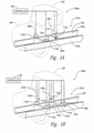
- Figure 1A is a partially schematic front isometric view of a vehicle 100a having a cab 102 mounted to a chassis 120 with a cab suspension control system 101a configured in accordance with an embodiment of the present technology.
- Figure 1B is a similar view of a vehicle 100b in which the cab 102 is mounted to the chassis 120 with a cab suspension control system 101b configured in accordance with another embodiment of the present technology.
- the chassis 120 includes a rear cross-member 124 extending between a left (e.g., driver side) frame rail 122a and a right (e.g., passenger side) frame rail 122b.
- the frame rails 122a, b extend longitudinally and generally parallel to the longitudinal axis of the vehicle 100a.
- the cab 102 is mounted to the left frame rail 122a at a left front mount location 106a, and to the right frame rail 122b at a right front mount location 106b.
- the aft portion of the cab 102 is mounted to the rear cross-member 124 at a rear mount location 108.
- the vehicle 100a includes an engine compartment at least partially enclosed by a hood 104 that is independently mounted to the chassis 120 forward of the cab 102.
- the suspension control system 101a includes isolators 112, such as semi-active elastomeric (e.g., rubber-based) isolators (identified individually as a left isolator 112a and a right isolator 112b) at each of the two front mount locations 106a, b. Additionally, the suspension control system 101a further includes a semi-active shock absorber 116 and an air spring 114 at the rear mount location 108. Although not shown in Figure 1A , the rear mount location 108 can also include a displacement or position sensor mounted between the cab 102 and the chassis 120 in conjunction with the air spring 114 and the shock absorber 116.
- isolators 112 such as semi-active elastomeric (e.g., rubber-based) isolators (identified individually as a left isolator 112a and a right isolator 112b) at each of the two front mount locations 106a, b.
- the suspension control system 101a further includes a semi-active shock
- each of the suspension components described above can be operably connected to a controller 130 (e.g., a vehicle ECU).
- the controller 130 is configured to receive dynamic (e.g., accelerometer) information and/or positional information from sensors mounted to the cab 102 and/or the chassis 120 proximate the front mount locations 106a, b, the rear mount location 108, and/or other locations on the vehicle 100a, and respond by providing control signals to the appropriate suspension components to adjust a suspension property (e.g., damping) and achieve better ride quality and/or road holding.
- the sensors can be dedicated sensors for use solely with the suspension control system 101a, or they be vehicle sensors that were originally provided with the vehicle by the manufacturer and accessed via the vehicle's Controller Area Network (CAN) system.
- CAN Controller Area Network
- the cab 102 is mounted to the frame rails 122a, b by means of an air spring 114 (identified individually as air springs 114a-d) and a corresponding shock absorber 116 (identified individually as shock absorbers 116a-d) at each of a left front mount location 107a, a right front mount location 107b, a left rear mount location 109a, and a right rear mount location 109b.
- each of the mount locations 107a, b and 109a, b can additionally include a displacement sensor in conjunction with the air spring 114 and shock absorber 116.
- the cab suspension control system 101b includes the controller 130 which is operably connected to each of the air springs 114 and shock absorbers 116 at the four cab mount locations.
- the cab mount configuration illustrated in Figure 1A (which employs the isolators 112a, b at the front mount locations 106a, b) may be most suitable for use with conventional truck or tractor cabs in which clearance between the cab 102 and the hood 104 ( Figure 1A ) is a primary concern.
- One reason for this is that the annular bodies or bushings 232 ( Figure 2 ) of the isolators 112 can restrict forward and aft motion of the cab, thereby limiting relative displacement between the cab 102 and the hood 104.
- the cab mount configuration illustrated in Figure 1B may be most suitable for non-conventional trucks or tractors (e.g., trucks or tractors having a cab-over configuration.)
- the controller 130 receives input (e.g., acceleration information, displacement information, etc.) from one or more sensors at or near the cab mount locations, and executes instructions stored on computer readable medium to determine the optimum (or at least a more favorable) operational state of the controllable suspension components at each mount location in accordance with one or more of the flow routines described below.
- the controller 130 then outputs a command signal to each of the suspension components to adjust the operating parameter of the component (e.g., the damping, height, etc.) to achieve the optimum (or at least more favorable) setting.
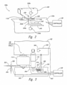
- FIG 2 is an enlarged, partially schematic isometric view of the left front mount location 106a configured in accordance with an embodiment of the present technology.
- the following discussion describing the left front mount location 106a applies equally to the right front mount location 106b ( Figure 1A ).
- the isolator 112a includes a cylindrical or annular body 232 (which can also be referred to as a bushing 232) supported in a rigid base 228.
- the base 228 can be fixedly attached to an upper surface of the left frame rail 122a with one or more bolts or other suitable attachment mechanisms well known in the art.
- the annular body 232 includes a central concentric bore or aperture configured to receive a shaft 230 (e.g., a bolt, pin, etc.) that pivotally couples a bracket 226 to the isolator 112a.
- the pivotal attachment of the bracket 226 to the isolator 112a enables the cab 102 to rotate about the shaft 230 as, for example, the rear portion of the cab 102 is raised or lowered by operation of the air spring 114.
- the left front corner portion of cab 102 ( Figure 1A ) can be fixedly attached to an upper portion of the bracket 226 by one or more bolts or other suitable attachment mechanisms to mount the left front corner of the cab 102 to the left frame rail 122a.
- one or more sensors can be operably mounted to the bracket 226 and/or the frame rail 122a to obtain dynamic and positional information relative to the cab 102 and the chassis 120.
- a first sensor such as an accelerometer 240a
- a second sensor such as accelerometer 240b
- the accelerometers 240a,b can be accelerometers configured and positioned to sense linear accelerations of the cab 102 and the frame rail 122a, respectively, along a vertical axis relative to the road surface.
- Suitable accelerometers can include, for example, the Continental BSZ 04 accelerometer available from Continental AG, Vahrenwalder Str.
- the first accelerometer 240a can be electrically and/or communicatively connected to the controller 130 ( Figure 1A ) via a first electrical lead or link 242 (e.g., one or more wires), and the second accelerometer 240b can be electrically and/or communicatively connected to the controller 130 via a second electrical link 243 (e.g., one or more wires).
- the accelerometers 240a, b can be provided specifically as part of the cab suspension control system 101a.
- one or both of the accelerometers 240a, b may be those that are already included on the vehicle and their signal input can be received by the controller 130 via the vehicle CAN system.
- sensors 240a, b of the illustrated embodiment are accelerometers, in other embodiments other types of sensors, including, angular acceleration sensors, angle sensors, current sensors, pressure sensors, strain gauges, etc. can be used to assess and evaluate movement of the cab 102 relative to, e.g., the chassis 120.
- the isolator 112a can be an elastomeric semi-active isolator.
- the annular body 232 can be formed from an elastomer (e.g., rubber, polybutadienes, polyisobutylenes, polyurethanes, etc.) of suitable hardness, and have relatively thick walls that enclose one or more internal chambers that are at least partially filled with a magnetorheological (MR) fluid.
- MR magnetorheological
- the MR fluid is composed of oil and varying percentages of ferrous particles (e.g., 20-50 microns in diameter) that have been coated with an anticoagulant material.
- Varying the magnetic field strength with an electromagnetic coil has the effect of changing the viscosity of the magneto-rheological fluid.
- the damping provided by the isolator 112a can be altered by subjecting the MR fluid to a magnetic field by applying electrical current to an electromagnet (not shown in Figure 2 ) positioned proximate the fluid by means of the controller 130.
- Application of the magnetic field alters the viscous properties of the MR fluid, which in turn changes the damping characteristics of the isolator 112a. More specifically, increasing the viscosity increases damping, while reducing viscosity reduces damping. Construction and operation of MR fluid-filled suspension devices are described in, for example, U.S. Patent No.
- the annular body 232 of the isolator 112a can include multiple internal chambers filled with conventional isolator fluid, and the opening size of an orifice positioned between adjacent chambers can be electronically controlled by the controller 130 to vary the damping provided by the isolator 112a.
- the annular body 232 can be formed from an MR elastomer or similar material that changes stiffness and damping properties in response to a magnetic field controlled by the controller 130.
- MR elastomer devices can be found in the publication titled " A State-of-the-Art Review on Magnetorheological Elastomer Devices," Yancheng Li et. al, 2014 .
- FIG. 3 is an enlarged, partially schematic front view of the rear cab mount location 108 shown in Figure 1A , configured in accordance with an embodiment of the present technology. Although Figure 3 depicts the suspension component arrangement at the rear mount location 108, the same arrangement of components (or at least a generally similar arrangement of components) also exists at each of the four cab mount locations shown in Figure 1B .
- each of the four corners of the cab 102 in Figure 1B is supported by an air spring 114 and a shock absorber 116, and thus the description of Figure 3 that follows applies to the rear mount location 108 of Figure 1A as well as the four corner mount locations 107a, b and 109a, b of Figure 1B .
- the air spring 114 has a lower end portion fixedly attached to the frame cross-member 124, and an upper end portion fixedly attached to a lower portion of the cab 102.
- the control of pressurized gas (e.g., air) into and out of the air spring 114 is controlled by an electrically actuated valve 350 that is in fluid communication with a fill conduit 352 and an exhaust conduit 354.
- the fill conduit 352 is operably coupled in fluid communication to a high pressure gas source.
- the valve 350 can be moved between “closed,” “fill” and “exhaust” positions in response to electrical commands from the controller 130 ( Figure 1A ) via an electrical link 346 (e.g., one or more wires).
- the semi-active shock absorber 116 includes a first or lower end portion fixedly attached to the rear cross-member 124 in a conventional manner, and an upper end portion fixedly attached to a lower portion of the cab 102 in a similarly conventional manner.
- the semi-active shock absorber 116 can be any type of semi-active electrically actuated shock absorber known to those of ordinary skill in the art.
- the semi-active shock absorber 116 can be a telescoping MR fluid-filled device in which the damping is varied by application of a magnetic field to the MR fluid.
- the shock absorber 116 can include an internal coil that receives control current from the controller 130 via an electrical link 344 (e.g., two wires).
- the shock absorber 116 can include MR or ER elastomers that provide varied damping via a change in a magnetic or electric field, respectively.
- the shock absorber 116 can include an adjustable orifice through which the shock absorber fluid passes and which can be electrically controlled to vary the orifice size and change the damping properties in response to a control signal from the controller 130.
- Various examples of semi-active shock absorbers and associated systems that can be included in the systems described herein are described in U.S. Pat. Nos. 6,070,681 , 6,904,344 , and 6,732,033 .
- an accelerometer 340 is mounted to a lower portion of the cab 102 proximate the shock absorber 116, and is electrically connected to the controller 130 via an electrical link 342 (e.g., one or more wires).
- an accelerometer could also be mounted to the cross-member 124 to obtain acceleration information relating to the chassis 120, in the illustrated embodiment a displacement or position sensor 318 is operably coupled between the cross-member 124 and the cab 102.
- the position sensor 318 includes a link 320 having an upper end portion pivotally attached to a lower portion of the cab 102, and an opposite lower end portion pivotally coupled to a distal end portion of a pivotable arm 322.
- the arm 322 is pivotally attached to the cross-member 124 via a pivot 324.
- up or down movement of the cab 102 relative to the cross-member 124 causes the link 320 to pivot the arm 322 upwardly and downwardly about the pivot 324.
- the position sensor 318 includes a sensing device that senses the angular movement of the arm 322 relative to the pivot 324, which can be calibrated to provide the vertical displacement of the cab 102 relative to the cross-member 124.
- the displacement information from the position sensor 318 is provided to the controller 130 via an electrical link 343 (e.g., one or more wires).
- the components described above with reference to Figure 3 can be implemented in various ways to semi-actively control the damping (or damping coefficient) at the respective cab mount locations, the ride height, and/or the extent of lateral roll of the cab 102.
- the ride height can be increased via a command signal from the controller 130 that opens the valve 350 and introduces high pressure gas into the air spring 114.
- the ride height can be reduced by a corresponding command signal that moves the valve 350 to the exhaust position allowing air to flow out of the air spring 114 via the exhaust conduit 354.
- vibration and other relative motion between the cab 102 and the chassis 120 can be controlled in real-time via command signals sent from the controller 130 to the shock absorber 116 to control, for example, the viscosity of the MR fluid (in the case of an MR fluid-filled shock absorber), and/or to vary a fluid orifice size (in the case of a shock absorber having variable orifice damping).
- the controller 130 can provide the command signals to the air spring 114 and/or the shock absorber 116 in response to and based on, for example, acceleration information from the accelerometer 340 and/or the displacement information from the position sensor 318.
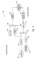
- FIGS 4A and 4B are block diagrams of the cab suspension control systems 101a and 101b, respectively, configured in accordance with embodiments of the present technology.
- the controller 130 receives input from the sensors at the front cab mount locations 106a, b and the rear mount location 108, and based on this input, outputs command signals to one or more of the controllable suspension components at the respective cab mount locations. More specifically, in the illustrated embodiment of Figure 4A , the controller 130 receives accelerometer output from the cab and frame accelerometers 240a-d at the front mount locations 106a, b, and output from the cab accelerometer 340 and the position sensor 318 at the rear cab mount location 108.
- the controller 130 processes the output from the sensors by executing non-transitory instructions stored on computer-readable media to determine appropriate command signals to output to the controllable suspension components (e.g., the isolators 112 and the damper 116) in real-time at the front mount locations 106 and the rear mount location 108 to achieve an improved or desired ride quality.
- improving ride quality can include reducing the vibration and shocks from road conditions, reducing body roll and pitch variation in driving situations such as cornering, accelerating and breaking, and/or improving road-holding. The foregoing are but some examples of the type of improved ride conditions that the systems described herein can achieve.
- the controller 130 receives input from the cab accelerometer 340 and the position sensor 318 at both of the two front mount cab mount locations 107a, b, and both of the rear cab mount locations 109a, b.
- the controller 130 processes this input in real time and outputs corresponding command signals to the controllable suspension components (e.g., the damper 116 and/or the air spring 114) at each of the front and rear cab mount locations to improve the ride, road-holding or a combination of the two for the vehicle 100b and/or the cab 102.
- the controllable suspension components e.g., the damper 116 and/or the air spring 11
- control systems described herein can comprise feedback loops that take the system output from the various sensors into consideration, and enable the system to adjust the performance of the controllable suspension components to attenuate or otherwise reduce undesirable ride or road-holding characteristics.
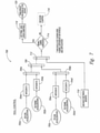
- FIG. 5 illustrates a logic diagram 500 for the suspension control system 101a described in detail above with reference to Figures 1A and 2-4A .
- the upper portion of the diagram 500 pertains to control of the front cab mount locations 106a, b, and the lower portion of the diagram 500 pertains to control of the rear cab mount location 108.
- the front mount locations 106a, b at blocks 502a-502d output from the driver side frame accelerometer 240b and the driver side cab accelerometer 240a ( Figure 2 ), and output from the corresponding passenger side frame accelerometer and the passenger side cab accelerometer, respectively, are provided to the controller 130 for execution of a roll control algorithm 504 and a skyhook control algorithm 506.
- the roll control algorithm 504 determines if the magnitude of the cab roll to one side or the other exceeds a preset threshold. If so, the roll control algorithm 504 outputs command signals to the two front isolators 112a, b to attenuate the roll as shown in block 508a. If not, the roll control algorithm 504 does not output command signals to the front isolators 112a, b, and instead defers to the skyhook control algorithm 506.
- the skyhook control algorithm 506 determines the appropriate output commands for the front isolators 112a, b to provide a desired level of damping, as shown in block 508b.
- the skyhook control algorithm 506 attempts to control the suspension components so that the cab maintains a stable ride in accordance with conventional skyhook theory.
- the skyhook control algorithm 506 can incorporate various other ride control algorithms known in the art to reduce ride vibration, shocks, etc.
- output from the rear cab accelerometer 340 ( Figure 3 ) is provided to the controller 130 for execution of the skyhook control algorithm 506, and at block 512 output from the rear cab position sensor 318 is provided to the controller 130 for execution of the skyhook control algorithm 506 and a height control algorithm 514.
- the skyhook control algorithm 506 determines the appropriate output command to vary the damping of the rear mount shock absorber 116 and provide the desired ride quality, as shown in block 516.
- the height control algorithm 514 determines whether the height of the air spring 114 should be adjusted. If so, the height control algorithm 514 can output an appropriate command to the air valve 350 ( Figure 3 ) to raise or lower the air spring 114 as necessary, as shown in block 518.
- Figure 6 is a flow diagram of a routine 600 (e.g., a skyhook control algorithm) for controlling one or more semi-active suspension components in accordance with embodiments of the present technology.
- the routine 600 can be implemented by the controller 130 in accordance with computer-readable instructions to provide real-time command signals to one or more semi-active suspension components (e.g., the isolators 112 and/or the shock absorbers 116) based on acceleration and/or displacement input from one or more cab mount locations or other locations on the cab 102 and/or on the chassis 120.
- one or more semi-active suspension components e.g., the isolators 112 and/or the shock absorbers 116
- routine 600 will be described in the context of the rear cab mount location 108 described above with reference to Figures 1A and 3 , with the understanding that the routine can also be implemented at either of the front isolator mount locations 106a, b of Figure 1A , or at any of the front or rear cab mount locations 107a, b and 109a, b, respectively, of Figure 1B .
- the routine 600 begins at blocks 602 and 606 by receiving cab acceleration data and suspension displacement data, respectively.
- the cab acceleration data can come from the cab accelerometer 340 shown in Figure 3
- the suspension displacement data can come from the position sensor 318 also shown in Figure 3 .
- the routine integrates the cab acceleration data to determine a cab velocity.
- the cab velocity will be positive when the cab is moving upward relative to the road surface, and negative when the cab is moving downward relative to road surface.
- the routine differentiates the suspension displacement data to determine the velocity of the suspension.
- the suspension velocity will be positive when the suspension is expanding (also known as rebound); that is, when the cab is moving away from the chassis.
- the suspension velocity will be negative when the suspension is compressing and the cab is moving toward the chassis.
- the cab velocity is multiplied by the suspension velocity and the product is provided to decision block 612 as a criteria signal.
- the routine determines if the signal is greater than zero (i.e., whether the signal is positive or negative). If the signal is less than zero (i.e., the signal is negative), this indicates that damping between the cab 102 and the chassis 120 should be decreased to best approximate a theoretical skyhook damper, as is well known to those of ordinary skill in the art, and the routine 600 proceeds to block 614.
- the pulse-width modulated signal that controls the voltage output to the semi-active suspension component e.g., the shock absorber 116) is set to a minimum value (typically zero) corresponding to the minimum damping state of the component, and this control signal is sent to the semi-active component driver at block 616.
- the routine proceeds to block 622.
- the absolute value of the cab velocity (block 618) is multiplied by a proportional gain (block 620), e.g., a proportional gain of 300, and the product is provided to block 624.
- the pulse-width modulated signal that controls the voltage output to the semi-active suspension component (e.g., the shock absorber 116) is varied in proportion to the absolute value of the cab velocity up to a maximum setting that is dependent on a particular suspension component.
- the routine increases the voltage output to the semi-active suspension component so that the damping is set at a maximum value.
- the suspension component is a shock absorber having an electronically variable fluid orifice between adjacent fluid chambers, the voltage signal would be set at a maximum value to reduce the orifice size to the minimum value and thereby maximize the damping effect.
- the suspension component included an MR fluid or an MR or ER elastomer, the voltage signal would be increased to achieve the highest damping possible from the MR or ER elastomer.
- Figure 7 is a flow diagram of a routine 700 for controlling roll (e.g., lateral roll) of a vehicle cab (e.g., the cab 102) relative to a vehicle chassis (e.g., the chassis 120) in accordance with an embodiment of the present technology.
- the routine 700 and/or portions thereof can be executed by the controller 130 in accordance with instructions stored on non-transitory computer-readable medium.
- the routine 700 will be described in the context of the suspension control system 101a described in detail above with reference to Figures 1A , 2 and 4A . In other embodiments, however, those of ordinary skill in the art will appreciate that the routine 700 can be similarly applied to other cab mounting systems in accordance with the present disclosure.
- output from the driver side cab accelerometer 240a ( Figure 2 ) is provided to block 704a.
- the driver side cab acceleration is integrated and the resulting velocity is provided to block 706a.
- output from the driver side frame accelerometer 240b is provided to block 704b.
- the driver side frame acceleration is integrated, and the resulting velocity is also provided to block 706a.
- the frame velocity is subtracted from the cab velocity, and the result is provided to block 708.
- the result of block 706a would be a net negative velocity associated with the driver side of the cab.
- a similar velocity is also determined for the passenger side of the cab. More specifically, at block 702c output from the passenger side cab accelerometer is provided to block 704c, where it is integrated to determine a passenger side cab velocity that is provided to block 706b. At block 702d, output from the passenger side frame accelerometer is provided to block 704d, where it is also integrated to determine a passenger side frame velocity which in turn is also provided to block 706b. In block 706b, the passenger side frame velocity is subtracted from the passenger side cab velocity as described above for block 706a, and the result is provided to block 708.
- the suspension velocities across the front cab mount locations 106a, b are combined. More specifically, the passenger side mount velocity from block 706b is subtracted from the driver side mount velocity from block 706a.
- the result of block 708 would be a positive velocity indicating at least some magnitude of roll of the vehicle cab about the longitudinal axis of the vehicle toward the passenger side.
- the distance (in, e.g., feet/inches) between the driver side and passenger side cab mount locations 106a and 106b ( Figure 1A ) is provided to block 712 along with the suspension velocity (in, e.g., feet per second) from block 708.
- the suspension velocity is divided by the lateral distance between the cab mount locations to provide an indication of the magnitude of the roll motion (e.g., an angular velocity) to decision block 714.
- the routine 700 determines if the criteria signal from block 712 is greater than a threshold tuning value.
- the threshold tuning value of roll (e.g., an angular velocity) can be determined during vehicle ride tuning, and can be dependent on the particular vehicle and/or the particular vehicle application. If the signal is not greater than the tuning threshold, the routine proceeds to block 716 and reverts to the skyhook control algorithm described above with reference to Figure 6 to determine the command signals for the suspension components. In the illustrated embodiment, however, if the roll signal is greater than the tuning threshold, the routine 700 proceeds to block 718 and sets the pulse-width modulated signal that controls the voltage output to the suspension components to the maximum value (e.g., the value resulting in the highest level of damping), and provides this control signal to the suspension component driver as indicated by block 720.
- the maximum value e.g., the value resulting in the highest level of damping
- the driver increases the damping provided by the isolators to the highest level to control the amount of roll the cab 102 is experiencing.
- FIG 8 is a flow diagram of a routine 800 for controlling cab height in accordance with an embodiment of the present technology.
- the routine 800 can be implemented by the controller 130 in accordance with instructions stored on computer-readable medium.
- the routine 800 is described below in the context of the suspension components used at the cab rear mount location 108 as described above with reference to Figures 1A , 3 and 4A .
- the routine 800 can be utilized at virtually any cab mounting location having, for example, an air spring or other controllable suspension component with which the cab height can be varied.
- the routine 800 can also be employed at one or more of the front mount locations 107a, b and/or the rear mount locations 109a, b described in detail above with reference to Figure 1B and Figure 4B .
- suspension displacement at the cab mount location is provided to decision block 804.
- the position sensor 318 described above with reference to Figure 3 can provide data indicative of the displacement of the cab 102 relative to the frame 120 to the controller 130.
- the routine determines if any of the valves for any of cab suspension air springs have been actuated. For example, in the context of Figure 3 , the routine determines if the valve 350 for the air spring 114 has been activated to either introduce high pressure into the air spring 114 and increase the ride height, or let air out of the air spring 114 and reduce the ride height.
- the routine 800 proceeds to block 806.
- the output signal from the position sensor 318 is lightly filtered so that relatively small changes in the suspension height resulting from air being added to or removed air from the air spring 114 can be readily detected. This enables the routine to respond quickly and turn the valve 350 "off” as soon as the signal indicates that the desired ride height has been achieved.
- the lighter filter prevents overshooting a desired suspension position, while still eliminating responses to high frequency suspension oscillations.
- the output signal from the displacement sensor can be lightly filtered by setting the cutoff frequency to a relatively high value.
- the routing proceeds to block 808 and heavily filters the output signal from the position sensor 318 before providing it to decision block 810.
- the position signal is heavily filtered when the valve 350 is off to avoid unnecessary cycling the valve 350 on and off and wasting the compressed air used to fill the air spring 114 in response to very short term (e.g., high frequency) signal inputs corresponding to minor vibrations or changes in position of the suspension.
- very short term e.g., high frequency
- decision block 810 determines whether the cab height is less than a preset distance below the suspension "design height” or "ride height.”
- a preset distance below the suspension "design height” or "ride height.”
- the routine proceeds to decision block 816 to determine if the valve 350 is set to the fill position so that compressed air is flowing into the air spring 114 to raise the cab 102.
- the routine proceeds to block 818 and turns the valve 350 to the fill position. Conversely, if the valve 350 is already in the fill position, the routine proceeds to block 814 and does not send any control signals to the valve 350.
- the routine proceeds to decision block 810, if the cab height is not less than -0.25 inch, the routine proceeds to decision block 812 and determines if the height is greater than +0.25 inch. If not, the routine proceeds to block 814 and takes no action. Conversely, if the cab height is greater than +0.25 inch, then the routine proceeds to decision block 820 to determine if the valve 350 is in the "exhaust" position such that compressed air is flowing out of the air spring 114 to reduce the cab height.
- valve 350 If the valve 350 is in the "exhaust” position, the routine proceeds to block 814 and takes no action (e.g., the routine does not send any control signals to the valve 350). Conversely, if the valve 350 is not in the "exhaust” position, the routine proceeds to block 822 and sends a control signal to the valve 350 causing the valve 350 to turn to the "exhaust” position so that compressed air can flow out of the air spring 114 and reduce the ride height of the cab.
- FIGS. 6-8 are representative flow diagrams that depict processes used in some embodiments. These flow diagrams do not show all functions or exchanges of data, but instead they provide an understanding of commands and data exchanged under the various embodiments of the suspension control systems disclosed herein. Those skilled in the relevant art will recognize that some functions or exchange of commands and data may be repeated, varied, omitted, or supplemented, and other (less important) aspects not shown may be readily implemented. In general, each of the steps depicted in the flow diagrams are of a type well known in the art, and can itself include a sequence of operations that need not be described herein. Those of ordinary skill in the art can create source code, microcode, program logic arrays, etc. for programming the controller 130 or otherwise implementing the disclosed embodiments based on the routines and detailed description provided herein.
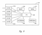
- FIG. 9 is a schematic diagram of the controller 130 configured in accordance with an embodiment of the present technology.
- the controller 130 includes at least one processor 902 (e.g., a CPU) that receives power from a power supply 906.
- the power supply 906 can include, for example, a dedicated battery or power from the vehicle power system.
- the controller 130 additionally includes a plurality of input/output ports 912 (identified individually as I/O ports 912a-n) for receiving input from the various sensors described in detail above (e.g., the accelerometers 240, 340 and the position sensor 318), and providing command signals to the various suspension components (e.g., the semi-active isolators 112, the semi-active shock absorber 116 and the air spring 114).
- the various suspension components e.g., the semi-active isolators 112, the semi-active shock absorber 116 and the air spring 114.
- the controller 130 can include an analog-to-digital converter 908 to convert analog signals, such as analog voltage or current signals from the sensors described above to digital information for the processor 902.
- the processor 902 can execute the routines described in detail above with reference to Figures 5-8 in accordance with non-transitory instructions stored on computer-readable medium, such as non-volatile memory 904, or stored on removable media, hardwired or preprogrammed in chips, such as EEPROM semiconductor chips.
- the controller 130 can include various other components as necessary to implement the routines described herein, including, for example, one or more timers 910, as well as other electronic components well known in the art.
- aspects of the invention are described in the general context of computer-executable instructions, such as routines executed by a general-purpose data processing device, e.g., a CPU.
- a general-purpose data processing device e.g., a CPU.
- PLCs Programmable Logic Controllers
- PICs Peripheral Interface Controllers
- the terms computer, controller, and the like are generally used interchangeably herein, and refer to any of the above devices and systems, as well as any data processor.
- aspects of the invention can be embodied in a special purpose computer or data processor that is specifically programmed, configured, or constructed to perform one or more of the computer-executable instructions explained in detail herein. While aspects of the invention, such as certain functions, are described as being performed exclusively on a single device, the invention can also be practiced in distributed environments where functions or modules are shared among disparate processing devices, which are linked through a communications network, such as a CAN system. Although specific circuitry is described above, those or ordinary skill in the art will recognize that a microprocessor-based system could also be used where any logical decisions are configured in software.
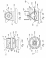
- FIGs 10A and 10B are front and side cross-sectional views, respectively, of the isolator 112a ( Figure 2 ) configured in accordance with an embodiment of the present technology.
- the isolator 112a includes a metal inner sleeve 1002 concentrically arranged inside of a metal outer sleeve 1004.
- the annular body 232 of the isolator 112 is sandwiched between the inner sleeve 1002 and the outer sleeve 1004.
- the cab 102 is mounted to the frame rail 122a by a bolt 1012 that extends through the cab mounting bracket 226 and the inner sleeve 1002.
- the outer sleeve 1004 is securely mounted to the isolator base 228, which is in turn attached to the frame rail 122a via bolts or other suitable attachment means.
- the annular body 232 of the isolator 112a can transmit the static loads and isolate the dynamic loads between the cab 102 and the frame rail 122a at the front mount location 106a.
- the annular body 232 can be made from an MR elastomer.
- the damping properties of the MR elastomer can be increased to dampen vibrations between the frame 122 and the cab 102 by applying current to an electromagnet 1010 positioned around or at least proximate the inner sleeve 1002 to increase the magnetic field applied to the MR elastomer.
- the annular body 232 can include one or more internal chambers that contain an MR fluid, and the damping properties of the isolator 112a can be varied by changing the magnetic field applied to the fluid.
- the annular body 232 can be made from an ER elastomer in which the damping properties of the isolator 112a can be varied dynamically by changing the electric field applied to the ER elastomer.
- Figure 11 is a side cross-sectional view of an isolator 1100 configured in accordance with another embodiment of the present technology.
- the isolator 1100 includes a metal inner sleeve 1102 positioned within a metal outer sleeve 1104.
- An outer liner 1106 is disposed against the inner surface of the outer sleeve 1104, and an inner liner 1108 is disposed around the outer surface of the inner sleeve 1102.
- the outer and inner liners 1106 and 1108 can be made from natural rubber or other elastomers.
- the outer liner 1106 defines an upper chamber 1112a that is in fluid communication with a lower chamber 1112b by means of passages 1114a, b on opposite sides of the inner liner 1108.
- the inner liner 1108 has a generally rectangular or square shape so that the passages 1114a, b are generally straight with parallel sidewalls.
- the volume between outer liner 1106 and the inner liner 1108 can be filled with fluid 1116.
- the isolator 1100 can include an end cap on each end to contain the fluid 1116 within the inner volume and give the isolator 1100 a generally cylindrical shape.
- the isolator 1100 can be installed between the cab 102 and the frame rail 122a in generally the same manner as the isolator 112a described above with reference to Figures 10A and 10B .
- a bolt (not shown in Figure 11 ) extending through the inner sleeve 1102 can couple the isolator 1100 to a cab mounting bracket, and the outer sleeve 1104 can be held in a base (also not shown) that is mounted to the frame rail 122a.
- the inner sleeve 1102 and the inner lining 1108 In operation, vertical movement of the cab 102 relative to the frame 122a causes the inner sleeve 1102 and the inner lining 1108 to move toward the corresponding chamber 1112a or 1112b, thereby driving the fluid 1116 from the chamber and into the other chamber through the channels 114.
- the viscosity of the fluid 1116 flowing between upper and lower chambers 1112a, b tends to dampen out the vertical motion.
- the fluid 1116 can be an MR fluid, and the damping can be increased if desired by applying current to an electromagnet 1110 which, in the illustrated embodiment, is positioned around the inner sleeve 1102.
- FIG. 12 is a front cross-sectional view of an isolator 1200 configured in accordance with another embodiment of the present technology.
- the isolator 1200 includes thick walls 1204 of elastomeric material (e.g., rubber) that define a generally conical upper chamber 1212a and a generally hemispherical lower chamber 1212b.
- a mounting plate 1202 is fixedly attached between the upper chamber 1212a and the lower chamber 1212b, and is attached to a frame mounting bracket 1228 with bolts or other suitable fasteners.
- the walls 1204 define a body of revolution that is symmetrical about a vertical axis.
- a threaded stud 1218 or other attachment feature is fixedly attached to the upper portion of the walls 1204, and is configured to receive an upper bracket 1226 that is attached to the cab 102.
- the upper and lower chambers 1212a, b can be filled with a compressible fluid 1216, such as a silicone-based fluid. Motion of the frame 122a relative to the cab 102 compresses the fluid 1216 resulting in a spring rate. Relative motion of the suspension also causes restricted flow of the fluid 1216 through an orifice 1206 that separates the upper chamber 1212a from the lower chamber 1212b, thereby providing damping.
- the Isolator 1200 can include an electrically controlled semi-active valve 1207 that receives control inputs via electrical leads 1242a, b (e.g., wires).
- the valve 1207 can vary the size of the orifice 1206 to provide a desired level of damping in response to the various types of sensor inputs described in detail above.
- the fluid 1216 can be an MR fluid
- the elastomeric walls 1204 can provide the desired spring rate of the isolator 1200.
- the orifice 1206 can be a fixed size, but the damping can be changed in response to control inputs by varying the current applied to an electromagnet (not shown) that can be mounted to, for example, the plate 1202 around or proximate the orifice 1206 to thereby increase the viscosity of the MR fluid.
Description
- The following disclosure relates generally to the field of vehicle suspension systems and, more particularly, to semi-active suspension systems for vehicle cabs.
- Various types of suspension systems for heavy duty trucks, trailers, buses, automobiles and other vehicles are known, and these include: passive systems, active systems, semi-active systems and adaptive systems. The suspension variables in a passive suspension system do not change over time (except through wear), and as a result suspension movement is determined entirely by the road surface and other external factors. In active suspension systems, actuators can exert an independent force on the suspension to improve the ride characteristics. Both semi-active and adaptive suspension systems can vary a property of the suspension, usually damping, to rapidly achieve a better ride, better road-hoiding, or a combination of the two. Semi-active suspension systems differ from adaptive suspension systems, however, in that the characteristics of the suspension change more rapidly in a semi-active suspension system.
- Semi-active suspension systems differ from active suspension systems in that less energy is used in semi-active suspension systems and, in contrast to active suspension systems, no direct force is applied to the suspension system via power input from a control system. Instead, a small amount of energy is used to change the characteristic (e.g., damping) of the suspension system by, for example, electronically varying the size of an orifice through which damping fluid passes. By way of example, in the event the vehicle experiences a shock, a semi-active suspension system can only operate to dissipate the energy from the shock and not to apply an independent force in the same direction as the suspension motion resulting from the shock. Accordingly, semi-active suspension systems use less energy and are thus less costly than active suspension systems, yet they can still provide ride benefits beyond what can be achieved with a passive or adaptive suspension system.
- Vehicle height control systems are also well known. A common height control system includes a mechanically actuated height control valve (e.g., a rotary valve) that controls the flow of pressurized air to and from one or more suspension air springs based on suspension motion. Operation of the height control valve can allow air to flow into the air spring to increase the height, or flow out of the air spring to reduce the height, in response to both dynamic events as well as changes in static load on the suspension. Some vehicles include electronic height control systems that operate one or more valves based on input from one or more height sensors. In such systems, dynamic events can be ignored so that the system only adjusts suspension height in response to changes in static load that affect the ride height. This has the benefit of considerably reducing air consumption by the height control system, and thereby improving fuel economy.
- Various types of cab mounting suspension systems are known. In one of the most common types used in the United States, the two front corners of the cab are mounted to the vehicle frame with passive rubber isolators, and the rear of the cab is mounted to the frame with either one or two air springs and corresponding shock absorbers. Another common configuration uses rubber isolators at each of the front and rear corners of the cab, or alternatively, rubber isolators at the two front corners and a single rubber isolator at the rear of the cab. Other configurations use air springs or air springs and shock absorber combinations at each of the four corners of the cab.
- Many of the suspension control systems available today only address one aspect of vehicle suspension (e.g., damping, ride height, etc.). Additionally, different suspension technologies can be used at the front and rear of the cab, and often each of the technologies is provided by a different manufacturer that provides a particular controller and control solution that is unique to their individual components. These factors prohibit combining multiple technologies in a cost-effective manner to provide a complete cab suspension solution that offers superior performance.
-
WO 2009/144174 A1 provides a tractor cab suspension. Each corner of the cab is supported by fluid damper/spring unit. The damper/spring unit at each of the two front corners of the cab is connected with the chassis via a link of a fixed length and which extends generally transverse relative to the chassis. The link is pivoted at one end on the chassis and at the other end on the cab about axes which extend generally longitudinal relative to the chassis. This connection allows generally vertical movement of the cab relative to the chassis but resists transverse movement of the cab relative to the chassis. A roll bar acting between the cab and chassis is provided to control roll of the cab relative to the chassis. -
US 5 390 121 A describes a suspension system including a first movable member such as a vehicle frame, body, or cab and a second moving member spaced apart therefrom such as a vehicle axle, A-arm, frame or other component. A spring flexibly interconnects first and second moving members. Varying road inputs will tend to compress and extend spring and at least two semi-active dampers which are placed in parallel spring relation therewith. Each semi-active damper includes a piston which is attached to piston rod, both of which are telescopically received within the damper body. The piston separates the internal cavity into a first fluid chamber and second fluid chamber. The piston rod connects to the first moving member via a connection, such as a rod end or circular or split elastomer. Likewise the damper body connects to second moving member via a second connection which also may be a rod end, circular or split elastomer bushing. -
WO 2009/150508 A1 discloses a tractor cab suspension system that has a single support unit which mounts one end of the cab from a chassis of a tractor. The single support unit acts as a noise isolator and does not allow significant vertical oscillation of the cab relative to the chassis but allows the cab to pivot relative to the chassis in pitch (P) and roll (R) modes. Cab support means is provided at the other end of the cab which supports the cab from the chassis and damps pitching of the cab about the single support. Roll damper means are also provided to damp rolling of the cab about the single support, and a control means extends between the cab and chassis which controls transverse movement of the cab relative to the chassis. -
DE 10 2011 120428 A1 relates to a height adjustment device for a driver's cab that is movable with respect to a vehicle frame. An air suspension is provided for the driver's cab for providing a spring action relative to the frame. The air suspension may also be implemented as a semi-active system, i.e. the pneumatic adjusting elements which form the air suspension, have an electronically adjustable damping. - It is the object of the present invention to provide an improved cab suspension system.
- This object is solved by the subject matter of the independent claims.
- Embodiments are defined by the dependent claims.
-
-
Figures 1A and 1B are partially schematic front isometric views of vehicles having semi-active suspension control systems configured in accordance with embodiments of the present technology. -
Figure 2 is an enlarged, partially schematic isometric view of a cab front mount location having a semi-active isolator configured in accordance with an embodiment of the present technology. -
Figure 3 is a partially schematic front view of a cab rear mount location having an arrangement of suspension components configured in accordance with an embodiment of the present technology. -
Figures 4A and 4B are block diagrams of two cab suspension system layouts configured in accordance with embodiments of the present technology. -
Figure 5 is a logic diagram of a cab suspension control system configured in accordance with an embodiment of the present technology. -
Figure 6 is a flow diagram of a routine for controlling cab damping in accordance with an embodiment of the present technology. -
Figure 7 is a flow diagram of a routine for controlling cab roll in accordance with the present technology. -
Figure 8 is a flow diagram of a routine for controlling cab height in accordance with an embodiment of the present technology. -
Figure 9 is a block diagram of a controller for use with cab suspension systems configured in accordance with the present technology. -
Figures 10A and 10B are front and side cross-sectional views, respectively, of a semi-active isolator configured in accordance with an embodiment of the present technology. -
Figure 11 is a side cross-sectional view of a semi-active isolator configured in accordance with another embodiment of the present technology. -
Figure 12 is a front cross-sectional view of a semi-active isolator configured in accordance with a further embodiment of the present technology. - The following disclosure describes various embodiments of vehicle cab suspension systems and, in particular, semi-active cab suspension control systems and associated components. As used herein, "cab" generally refers to the portion of the vehicle (e.g., a heavy duty truck) in which the operator sits. In some embodiments, the cab suspension control systems described herein include mounting components at each of the cab mount locations that are controlled by a single controller (e.g. the vehicle Electronic Control Unit (ECU)). The systems described herein can be configured to accommodate various vehicle platforms, but each can include one or more of the following: air springs, shock absorbers, isolators, etc., which can be controlled to provide variable damping force, position (height), stiffness, etc. As described in further detail below, in some embodiments the systems can receive motion and positional information from various sensors (e.g., accelerometers, height sensors, pressure sensors, etc.) mounted to the cab and/or the vehicle frame, and/or from the vehicle Controller Area Network (CAN). In operation, the controller executes one or more algorithms to determine the optimum (or at least a more optimum) operating parameter for each of the control variables of the controlled suspension components, and then provides the appropriate control signals to the suspension components to achieve the desired performance.
- Certain details are set forth in the following description and in
Figures 1- 12 to provide a thorough understanding of various embodiments of the present technology. In other instances, well-known structures, methods, systems, materials and/or operations often associated with trucks and other on or off road vehicles, vehicle suspension systems, control systems, etc. are not shown or described in detail in the following disclosure to avoid unnecessarily obscuring the description of the various embodiments of the technology. Those of ordinary skill in the art will recognize, however, that the present technology can be practiced without one or more of the details set forth herein, or with other structures, methods, components, and so forth. - The terminology used below is to be interpreted in its broadest reasonable manner, even though it is being used in conjunction with a detailed description of certain examples of embodiments of the technology. Indeed, certain terms may even be emphasized below; however, any terminology intended to be interpreted in any restricted manner will be overtly and specifically defined as such in this Detailed Description section.
- The accompanying Figures depict embodiments of the present technology and are not intended to be limiting of its scope. The sizes of various depicted elements are not necessarily drawn to scale, and these various elements may be arbitrarily enlarged to improve legibility. Component details may be abstracted in the Figures to exclude details such as position of components and certain precise connections between such components when such details are unnecessary for a complete understanding of how to make and use the invention. Many of the details, dimensions, angles and other features shown in the Figures are merely illustrative of particular embodiments of the disclosure. In addition, those of ordinary skill in the art will appreciate that further embodiments of the invention can be practiced without several of the details described below.
- For ease of reference, identical reference numbers in the Figures identify identical, or at least generally similar, elements. To facilitate the discussion of any particular element, the most significant digit or digits of any reference number refers to the Figure in which that element is first introduced. For example, element 110 is first introduced and discussed with reference to
Figure 1 . -
Figure 1A is a partially schematic front isometric view of avehicle 100a having acab 102 mounted to achassis 120 with a cabsuspension control system 101a configured in accordance with an embodiment of the present technology.Figure 1B is a similar view of avehicle 100b in which thecab 102 is mounted to thechassis 120 with a cabsuspension control system 101b configured in accordance with another embodiment of the present technology. Referring first toFigure 1A , in the illustrated embodiment, thechassis 120 includes arear cross-member 124 extending between a left (e.g., driver side)frame rail 122a and a right (e.g., passenger side)frame rail 122b. In the illustrated embodiment, theframe rails 122a, b extend longitudinally and generally parallel to the longitudinal axis of thevehicle 100a. Thecab 102 is mounted to theleft frame rail 122a at a leftfront mount location 106a, and to theright frame rail 122b at a rightfront mount location 106b. The aft portion of thecab 102 is mounted to therear cross-member 124 at arear mount location 108. Thevehicle 100a includes an engine compartment at least partially enclosed by ahood 104 that is independently mounted to thechassis 120 forward of thecab 102. - In the illustrated embodiment, the
suspension control system 101a includes isolators 112, such as semi-active elastomeric (e.g., rubber-based) isolators (identified individually as aleft isolator 112a and aright isolator 112b) at each of the twofront mount locations 106a, b. Additionally, thesuspension control system 101a further includes asemi-active shock absorber 116 and anair spring 114 at therear mount location 108. Although not shown inFigure 1A , therear mount location 108 can also include a displacement or position sensor mounted between thecab 102 and thechassis 120 in conjunction with theair spring 114 and theshock absorber 116. In one aspect of this embodiment, each of the suspension components described above (e.g., the isolators 112, theair spring 114 and the shock absorber 116) can be operably connected to a controller 130 (e.g., a vehicle ECU). As described in further detail below, thecontroller 130 is configured to receive dynamic (e.g., accelerometer) information and/or positional information from sensors mounted to thecab 102 and/or thechassis 120 proximate thefront mount locations 106a, b, therear mount location 108, and/or other locations on thevehicle 100a, and respond by providing control signals to the appropriate suspension components to adjust a suspension property (e.g., damping) and achieve better ride quality and/or road holding. The sensors can be dedicated sensors for use solely with thesuspension control system 101a, or they be vehicle sensors that were originally provided with the vehicle by the manufacturer and accessed via the vehicle's Controller Area Network (CAN) system. - Turning next to
Figure 1B , in this embodiment thecab 102 is mounted to theframe rails 122a, b by means of an air spring 114 (identified individually as air springs 114a-d) and a corresponding shock absorber 116 (identified individually as shock absorbers 116a-d) at each of a leftfront mount location 107a, a rightfront mount location 107b, a leftrear mount location 109a, and a rightrear mount location 109b. Although not shown inFigure 1B , each of themount locations 107a, b and 109a, b can additionally include a displacement sensor in conjunction with theair spring 114 andshock absorber 116. As with the cabsuspension control system 101a described above, the cabsuspension control system 101b includes thecontroller 130 which is operably connected to each of the air springs 114 andshock absorbers 116 at the four cab mount locations. - The cab mount configuration illustrated in
Figure 1A (which employs theisolators 112a, b at thefront mount locations 106a, b) may be most suitable for use with conventional truck or tractor cabs in which clearance between thecab 102 and the hood 104 (Figure 1A ) is a primary concern. One reason for this is that the annular bodies or bushings 232 (Figure 2 ) of the isolators 112 can restrict forward and aft motion of the cab, thereby limiting relative displacement between thecab 102 and thehood 104. In other instances, the cab mount configuration illustrated inFigure 1B may be most suitable for non-conventional trucks or tractors (e.g., trucks or tractors having a cab-over configuration.) - In operation, the
controller 130 receives input (e.g., acceleration information, displacement information, etc.) from one or more sensors at or near the cab mount locations, and executes instructions stored on computer readable medium to determine the optimum (or at least a more favorable) operational state of the controllable suspension components at each mount location in accordance with one or more of the flow routines described below. Thecontroller 130 then outputs a command signal to each of the suspension components to adjust the operating parameter of the component (e.g., the damping, height, etc.) to achieve the optimum (or at least more favorable) setting. -
Figure 2 is an enlarged, partially schematic isometric view of the leftfront mount location 106a configured in accordance with an embodiment of the present technology. The following discussion describing the leftfront mount location 106a applies equally to the rightfront mount location 106b (Figure 1A ). In the illustrated embodiment, theisolator 112a includes a cylindrical or annular body 232 (which can also be referred to as a bushing 232) supported in arigid base 228. The base 228 can be fixedly attached to an upper surface of theleft frame rail 122a with one or more bolts or other suitable attachment mechanisms well known in the art. Theannular body 232 includes a central concentric bore or aperture configured to receive a shaft 230 (e.g., a bolt, pin, etc.) that pivotally couples abracket 226 to theisolator 112a. The pivotal attachment of thebracket 226 to theisolator 112a enables thecab 102 to rotate about theshaft 230 as, for example, the rear portion of thecab 102 is raised or lowered by operation of theair spring 114. Although not depicted inFigure 2 , the left front corner portion of cab 102 (Figure 1A ) can be fixedly attached to an upper portion of thebracket 226 by one or more bolts or other suitable attachment mechanisms to mount the left front corner of thecab 102 to theleft frame rail 122a. - In the illustrated embodiment, one or more sensors can be operably mounted to the
bracket 226 and/or theframe rail 122a to obtain dynamic and positional information relative to thecab 102 and thechassis 120. For example, in the illustrated embodiment a first sensor, such as an accelerometer 240a, is fixedly attached to thebracket 226, and a second sensor, such asaccelerometer 240b, is fixedly attached to theframe rail 122a. In some embodiments, the accelerometers 240a,b can be accelerometers configured and positioned to sense linear accelerations of thecab 102 and theframe rail 122a, respectively, along a vertical axis relative to the road surface. Suitable accelerometers can include, for example, the Continental BSZ 04 accelerometer available from Continental AG, Vahrenwalder Str. 9, D-30001 Hanover, Germany. The first accelerometer 240a can be electrically and/or communicatively connected to the controller 130 (Figure 1A ) via a first electrical lead or link 242 (e.g., one or more wires), and thesecond accelerometer 240b can be electrically and/or communicatively connected to thecontroller 130 via a second electrical link 243 (e.g., one or more wires). In some embodiments, the accelerometers 240a, b can be provided specifically as part of the cabsuspension control system 101a. In other embodiments, one or both of the accelerometers 240a, b may be those that are already included on the vehicle and their signal input can be received by thecontroller 130 via the vehicle CAN system. Although the sensors 240a, b of the illustrated embodiment are accelerometers, in other embodiments other types of sensors, including, angular acceleration sensors, angle sensors, current sensors, pressure sensors, strain gauges, etc. can be used to assess and evaluate movement of thecab 102 relative to, e.g., thechassis 120. - As noted above, in some embodiments the
isolator 112a can be an elastomeric semi-active isolator. For example, in some embodiments theannular body 232 can be formed from an elastomer (e.g., rubber, polybutadienes, polyisobutylenes, polyurethanes, etc.) of suitable hardness, and have relatively thick walls that enclose one or more internal chambers that are at least partially filled with a magnetorheological (MR) fluid. As is known, in MR fluid-based semi-active suspension systems, the MR fluid is composed of oil and varying percentages of ferrous particles (e.g., 20-50 microns in diameter) that have been coated with an anticoagulant material. Varying the magnetic field strength with an electromagnetic coil has the effect of changing the viscosity of the magneto-rheological fluid. In these embodiments, the damping provided by theisolator 112a can be altered by subjecting the MR fluid to a magnetic field by applying electrical current to an electromagnet (not shown inFigure 2 ) positioned proximate the fluid by means of thecontroller 130. Application of the magnetic field alters the viscous properties of the MR fluid, which in turn changes the damping characteristics of theisolator 112a. More specifically, increasing the viscosity increases damping, while reducing viscosity reduces damping. Construction and operation of MR fluid-filled suspension devices are described in, for example,U.S. Patent No. 6,070.681 , and the publication titled "Reducina Noise and Vibration of Hydraulic Hybrid and Plug-in Hybrid Electric Vehicles," Elahinia, 2012. In examples which are not claimed, instead of using an MR fluid-filled isolator, theannular body 232 of theisolator 112a can include multiple internal chambers filled with conventional isolator fluid, and the opening size of an orifice positioned between adjacent chambers can be electronically controlled by thecontroller 130 to vary the damping provided by theisolator 112a. - In a further embodiment, rather than being filed with an MR fluid, the
annular body 232 can be formed from an MR elastomer or similar material that changes stiffness and damping properties in response to a magnetic field controlled by thecontroller 130. A description of various MR elastomer devices can be found in the publication titled "A State-of-the-Art Review on Magnetorheological Elastomer Devices," Yancheng Li et. al, 2014. In either of the MR fluid or MR elastomer embodiments, there would be at least two electrical leads 244a, b (e.g., wires) completing a circuit from a power source controlled by thecontroller 130 to a coil positioned within or at least proximate theannular body 232. Current supplied to the coil via the circuit generates a magnetic field that changes the damping properties of the isolator 112a via either the MR fluid or the MR elastomer. In other examples not claimed , theannular body 232 can be formed from an electrorheological elastomer that similarly changes damping properties in response to an electric field activated by thecontroller 130 via the leads 244a, b.Figure 3 is an enlarged, partially schematic front view of the rearcab mount location 108 shown inFigure 1A , configured in accordance with an embodiment of the present technology. AlthoughFigure 3 depicts the suspension component arrangement at therear mount location 108, the same arrangement of components (or at least a generally similar arrangement of components) also exists at each of the four cab mount locations shown inFigure 1B . More specifically, as noted above each of the four corners of thecab 102 inFigure 1B is supported by anair spring 114 and ashock absorber 116, and thus the description ofFigure 3 that follows applies to therear mount location 108 ofFigure 1A as well as the fourcorner mount locations 107a, b and 109a, b ofFigure 1B . - In the illustrated embodiment, the
air spring 114 has a lower end portion fixedly attached to theframe cross-member 124, and an upper end portion fixedly attached to a lower portion of thecab 102. The control of pressurized gas (e.g., air) into and out of theair spring 114 is controlled by an electrically actuatedvalve 350 that is in fluid communication with afill conduit 352 and anexhaust conduit 354. Thefill conduit 352 is operably coupled in fluid communication to a high pressure gas source. Thevalve 350 can be moved between "closed," "fill" and "exhaust" positions in response to electrical commands from the controller 130 (Figure 1A ) via an electrical link 346 (e.g., one or more wires). - In the illustrated embodiment, the
semi-active shock absorber 116 includes a first or lower end portion fixedly attached to therear cross-member 124 in a conventional manner, and an upper end portion fixedly attached to a lower portion of thecab 102 in a similarly conventional manner. Thesemi-active shock absorber 116 can be any type of semi-active electrically actuated shock absorber known to those of ordinary skill in the art. For example, in some embodiments, thesemi-active shock absorber 116 can be a telescoping MR fluid-filled device in which the damping is varied by application of a magnetic field to the MR fluid. More specifically, in the illustrated embodiment, theshock absorber 116 can include an internal coil that receives control current from thecontroller 130 via an electrical link 344 (e.g., two wires). In other embodiments, theshock absorber 116 can include MR or ER elastomers that provide varied damping via a change in a magnetic or electric field, respectively. In yet other embodiments, theshock absorber 116 can include an adjustable orifice through which the shock absorber fluid passes and which can be electrically controlled to vary the orifice size and change the damping properties in response to a control signal from thecontroller 130. Various examples of semi-active shock absorbers and associated systems that can be included in the systems described herein are described inU.S. Pat. Nos. 6,070,681 ,6,904,344 , and6,732,033 . - As noted above, various types of sensors can be used to obtain information regarding the acceleration, speed, and/or displacement of the
cab 102 relative to, for example, thechassis 120. For example, in the illustrated embodiment anaccelerometer 340 is mounted to a lower portion of thecab 102 proximate theshock absorber 116, and is electrically connected to thecontroller 130 via an electrical link 342 (e.g., one or more wires). Although an accelerometer could also be mounted to the cross-member 124 to obtain acceleration information relating to thechassis 120, in the illustrated embodiment a displacement orposition sensor 318 is operably coupled between the cross-member 124 and thecab 102. More specifically, in this embodiment theposition sensor 318 includes alink 320 having an upper end portion pivotally attached to a lower portion of thecab 102, and an opposite lower end portion pivotally coupled to a distal end portion of apivotable arm 322. Thearm 322 is pivotally attached to the cross-member 124 via apivot 324. In operation, up or down movement of thecab 102 relative to the cross-member 124 causes thelink 320 to pivot thearm 322 upwardly and downwardly about thepivot 324. Theposition sensor 318 includes a sensing device that senses the angular movement of thearm 322 relative to thepivot 324, which can be calibrated to provide the vertical displacement of thecab 102 relative to thecross-member 124. One type of suitable position sensor is the Continental Chassis Position Sensor (CPS) available from Continental AG, Vahrenwalder Str. 9, D-30001 Hanover, Germany. However, any suitable position or displacement sensor known in the art can be used with the systems described herein. The displacement information from theposition sensor 318 is provided to thecontroller 130 via an electrical link 343 (e.g., one or more wires). - As described in greater detail below, the components described above with reference to
Figure 3 can be implemented in various ways to semi-actively control the damping (or damping coefficient) at the respective cab mount locations, the ride height, and/or the extent of lateral roll of thecab 102. For example, the ride height can be increased via a command signal from thecontroller 130 that opens thevalve 350 and introduces high pressure gas into theair spring 114. Similarly, the ride height can be reduced by a corresponding command signal that moves thevalve 350 to the exhaust position allowing air to flow out of theair spring 114 via theexhaust conduit 354. Additionally, vibration and other relative motion between thecab 102 and thechassis 120 can be controlled in real-time via command signals sent from thecontroller 130 to theshock absorber 116 to control, for example, the viscosity of the MR fluid (in the case of an MR fluid-filled shock absorber), and/or to vary a fluid orifice size (in the case of a shock absorber having variable orifice damping). As described in greater detail below, thecontroller 130 can provide the command signals to theair spring 114 and/or theshock absorber 116 in response to and based on, for example, acceleration information from theaccelerometer 340 and/or the displacement information from theposition sensor 318. -
Figures 4A and 4B are block diagrams of the cabsuspension control systems Figure 4A , in thesuspension control system 101a thecontroller 130 receives input from the sensors at the frontcab mount locations 106a, b and therear mount location 108, and based on this input, outputs command signals to one or more of the controllable suspension components at the respective cab mount locations. More specifically, in the illustrated embodiment ofFigure 4A , thecontroller 130 receives accelerometer output from the cab and frame accelerometers 240a-d at thefront mount locations 106a, b, and output from thecab accelerometer 340 and theposition sensor 318 at the rearcab mount location 108. Thecontroller 130 processes the output from the sensors by executing non-transitory instructions stored on computer-readable media to determine appropriate command signals to output to the controllable suspension components (e.g., the isolators 112 and the damper 116) in real-time at the front mount locations 106 and therear mount location 108 to achieve an improved or desired ride quality. As used herein, improving ride quality can include reducing the vibration and shocks from road conditions, reducing body roll and pitch variation in driving situations such as cornering, accelerating and breaking, and/or improving road-holding. The foregoing are but some examples of the type of improved ride conditions that the systems described herein can achieve. - Turning next to
Figure 4B , in the illustrated embodiment of thesuspension control system 101b, thecontroller 130 receives input from thecab accelerometer 340 and theposition sensor 318 at both of the two front mountcab mount locations 107a, b, and both of the rearcab mount locations 109a, b. Thecontroller 130 processes this input in real time and outputs corresponding command signals to the controllable suspension components (e.g., thedamper 116 and/or the air spring 114) at each of the front and rear cab mount locations to improve the ride, road-holding or a combination of the two for thevehicle 100b and/or thecab 102. As those of ordinary skill in the art will appreciate, the control systems described herein can comprise feedback loops that take the system output from the various sensors into consideration, and enable the system to adjust the performance of the controllable suspension components to attenuate or otherwise reduce undesirable ride or road-holding characteristics. -
Figure 5 illustrates a logic diagram 500 for thesuspension control system 101a described in detail above with reference toFigures 1A and2-4A . The upper portion of the diagram 500 pertains to control of the frontcab mount locations 106a, b, and the lower portion of the diagram 500 pertains to control of the rearcab mount location 108. With respect to thefront mount locations 106a, b, at blocks 502a-502d output from the driverside frame accelerometer 240b and the driver side cab accelerometer 240a (Figure 2 ), and output from the corresponding passenger side frame accelerometer and the passenger side cab accelerometer, respectively, are provided to thecontroller 130 for execution of aroll control algorithm 504 and askyhook control algorithm 506. As described in greater detail below with reference to, e.g.,Figure 7 , based on the output from the front cab and frame accelerometers, theroll control algorithm 504 determines if the magnitude of the cab roll to one side or the other exceeds a preset threshold. If so, theroll control algorithm 504 outputs command signals to the twofront isolators 112a, b to attenuate the roll as shown inblock 508a. If not, theroll control algorithm 504 does not output command signals to thefront isolators 112a, b, and instead defers to theskyhook control algorithm 506. As described in detail below with reference to, e.g.,Figure 6 , based on the output from the front cab and frame accelerometers, theskyhook control algorithm 506 determines the appropriate output commands for thefront isolators 112a, b to provide a desired level of damping, as shown inblock 508b. In some embodiments, theskyhook control algorithm 506 attempts to control the suspension components so that the cab maintains a stable ride in accordance with conventional skyhook theory. In other embodiments, theskyhook control algorithm 506 can incorporate various other ride control algorithms known in the art to reduce ride vibration, shocks, etc. - Turning next to the rear cab mount location, at
block 510 output from the rear cab accelerometer 340 (Figure 3 ) is provided to thecontroller 130 for execution of theskyhook control algorithm 506, and atblock 512 output from the rearcab position sensor 318 is provided to thecontroller 130 for execution of theskyhook control algorithm 506 and aheight control algorithm 514. As described in detail below with reference to, for example,Figure 6 , based on the output from therear cab accelerometer 340 and the rearcab position sensor 318, theskyhook control algorithm 506 determines the appropriate output command to vary the damping of the rearmount shock absorber 116 and provide the desired ride quality, as shown inblock 516. As described in detail below with reference to, for example,Figure 8 , based on the input from the rearcab position sensor 318, theheight control algorithm 514 determines whether the height of theair spring 114 should be adjusted. If so, theheight control algorithm 514 can output an appropriate command to the air valve 350 (Figure 3 ) to raise or lower theair spring 114 as necessary, as shown inblock 518. -
Figure 6 is a flow diagram of a routine 600 (e.g., a skyhook control algorithm) for controlling one or more semi-active suspension components in accordance with embodiments of the present technology. The routine 600 can be implemented by thecontroller 130 in accordance with computer-readable instructions to provide real-time command signals to one or more semi-active suspension components (e.g., the isolators 112 and/or the shock absorbers 116) based on acceleration and/or displacement input from one or more cab mount locations or other locations on thecab 102 and/or on thechassis 120. By way of example, the routine 600 will be described in the context of the rearcab mount location 108 described above with reference toFigures 1A and3 , with the understanding that the routine can also be implemented at either of the frontisolator mount locations 106a, b ofFigure 1A , or at any of the front or rearcab mount locations 107a, b and 109a, b, respectively, ofFigure 1B . - The routine 600 begins at
blocks cab accelerometer 340 shown inFigure 3 , and the suspension displacement data can come from theposition sensor 318 also shown inFigure 3 . Inblock 604, the routine integrates the cab acceleration data to determine a cab velocity. In this embodiment, the cab velocity will be positive when the cab is moving upward relative to the road surface, and negative when the cab is moving downward relative to road surface. Inblock 608 the routine differentiates the suspension displacement data to determine the velocity of the suspension. In this embodiment, the suspension velocity will be positive when the suspension is expanding (also known as rebound); that is, when the cab is moving away from the chassis. Correspondingly, the suspension velocity will be negative when the suspension is compressing and the cab is moving toward the chassis. Inblock 610, the cab velocity is multiplied by the suspension velocity and the product is provided to decision block 612 as a criteria signal. - In
decision block 612, the routine determines if the signal is greater than zero (i.e., whether the signal is positive or negative). If the signal is less than zero (i.e., the signal is negative), this indicates that damping between thecab 102 and thechassis 120 should be decreased to best approximate a theoretical skyhook damper, as is well known to those of ordinary skill in the art, and the routine 600 proceeds to block 614. In block 614, the pulse-width modulated signal that controls the voltage output to the semi-active suspension component (e.g., the shock absorber 116) is set to a minimum value (typically zero) corresponding to the minimum damping state of the component, and this control signal is sent to the semi-active component driver atblock 616. - Returning to decision block 612, if the criteria signal is greater than zero (i.e., the signal is positive) this indicates that ride comfort would be improved by increasing the damping provided by the semi-active suspension component, and the routine proceeds to block 622. At
block 622 the absolute value of the cab velocity (block 618) is multiplied by a proportional gain (block 620), e.g., a proportional gain of 300, and the product is provided to block 624. Inblock 624, the pulse-width modulated signal that controls the voltage output to the semi-active suspension component (e.g., the shock absorber 116) is varied in proportion to the absolute value of the cab velocity up to a maximum setting that is dependent on a particular suspension component. For example, if the cab velocity is relatively high atblock 624, the routine increases the voltage output to the semi-active suspension component so that the damping is set at a maximum value. If the suspension component is a shock absorber having an electronically variable fluid orifice between adjacent fluid chambers, the voltage signal would be set at a maximum value to reduce the orifice size to the minimum value and thereby maximize the damping effect. If instead the suspension component included an MR fluid or an MR or ER elastomer, the voltage signal would be increased to achieve the highest damping possible from the MR or ER elastomer. -
Figure 7 is a flow diagram of a routine 700 for controlling roll (e.g., lateral roll) of a vehicle cab (e.g., the cab 102) relative to a vehicle chassis (e.g., the chassis 120) in accordance with an embodiment of the present technology. In some embodiments, the routine 700 and/or portions thereof can be executed by thecontroller 130 in accordance with instructions stored on non-transitory computer-readable medium. By way of example, the routine 700 will be described in the context of thesuspension control system 101a described in detail above with reference toFigures 1A ,2 and4A . In other embodiments, however, those of ordinary skill in the art will appreciate that the routine 700 can be similarly applied to other cab mounting systems in accordance with the present disclosure. Inblock 702a, output from the driver side cab accelerometer 240a (Figure 2 ) is provided to block 704a. Inblock 704a, the driver side cab acceleration is integrated and the resulting velocity is provided to block 706a. Similarly, atblock 702b output from the driverside frame accelerometer 240b is provided to block 704b. Inblock 704b, the driver side frame acceleration is integrated, and the resulting velocity is also provided to block 706a. Inblock 706a, the frame velocity is subtracted from the cab velocity, and the result is provided to block 708. By way of example, if the frame is moving upward (positive velocity) and the cab is moving downward (negative velocity), the result ofblock 706a would be a net negative velocity associated with the driver side of the cab. - A similar velocity is also determined for the passenger side of the cab. More specifically, at
block 702c output from the passenger side cab accelerometer is provided to block 704c, where it is integrated to determine a passenger side cab velocity that is provided to block 706b. Atblock 702d, output from the passenger side frame accelerometer is provided to block 704d, where it is also integrated to determine a passenger side frame velocity which in turn is also provided to block 706b. Inblock 706b, the passenger side frame velocity is subtracted from the passenger side cab velocity as described above forblock 706a, and the result is provided to block 708. Inblock 708, the suspension velocities across the frontcab mount locations 106a, b (which are located at the same, or at least approximately the same longitudinal position along the vehicle frame), are combined. More specifically, the passenger side mount velocity fromblock 706b is subtracted from the driver side mount velocity fromblock 706a. By way of example, if the driver side of thecab 102 is moving away from the driver side frame rail (resulting in a positive velocity fromblock 706a), and the passenger side of thecab 102 is moving toward the passenger side frame rail (resulting in a negative velocity fromblock 706b), then the result ofblock 708 would be a positive velocity indicating at least some magnitude of roll of the vehicle cab about the longitudinal axis of the vehicle toward the passenger side. - n block 710, the distance (in, e.g., feet/inches) between the driver side and passenger side
cab mount locations Figure 1A ) is provided to block 712 along with the suspension velocity (in, e.g., feet per second) fromblock 708. Inblock 712, the suspension velocity is divided by the lateral distance between the cab mount locations to provide an indication of the magnitude of the roll motion (e.g., an angular velocity) todecision block 714. Indecision block 714, the routine 700 determines if the criteria signal fromblock 712 is greater than a threshold tuning value. In some embodiments, the threshold tuning value of roll (e.g., an angular velocity) can be determined during vehicle ride tuning, and can be dependent on the particular vehicle and/or the particular vehicle application. If the signal is not greater than the tuning threshold, the routine proceeds to block 716 and reverts to the skyhook control algorithm described above with reference toFigure 6 to determine the command signals for the suspension components. In the illustrated embodiment, however, if the roll signal is greater than the tuning threshold, the routine 700 proceeds to block 718 and sets the pulse-width modulated signal that controls the voltage output to the suspension components to the maximum value (e.g., the value resulting in the highest level of damping), and provides this control signal to the suspension component driver as indicated byblock 720. For example, if thecab 102 is supported by the semi-active isolators 112 at each of the twofront mount locations 106a, b as described above with reference toFigure 1A , atblock 720 the driver increases the damping provided by the isolators to the highest level to control the amount of roll thecab 102 is experiencing. -
Figure 8 is a flow diagram of a routine 800 for controlling cab height in accordance with an embodiment of the present technology. The routine 800 can be implemented by thecontroller 130 in accordance with instructions stored on computer-readable medium. By way of example, the routine 800 is described below in the context of the suspension components used at the cabrear mount location 108 as described above with reference toFigures 1A ,3 and4A . As those of ordinary skill in the art will appreciate, however, the routine 800 can be utilized at virtually any cab mounting location having, for example, an air spring or other controllable suspension component with which the cab height can be varied. For example, the routine 800 can also be employed at one or more of thefront mount locations 107a, b and/or therear mount locations 109a, b described in detail above with reference toFigure 1B andFigure 4B . - Starting in
block 802, suspension displacement at the cab mount location is provided todecision block 804. By way of example, in one embodiment theposition sensor 318 described above with reference toFigure 3 can provide data indicative of the displacement of thecab 102 relative to theframe 120 to thecontroller 130. Indecision block 804, the routine determines if any of the valves for any of cab suspension air springs have been actuated. For example, in the context ofFigure 3 , the routine determines if thevalve 350 for theair spring 114 has been activated to either introduce high pressure into theair spring 114 and increase the ride height, or let air out of theair spring 114 and reduce the ride height. If thevalve 350 is "on" so that theair spring 114 is either filling (extending) or exhausting (compressing) to adjust the ride height, the routine 800 proceeds to block 806. Inblock 806, the output signal from theposition sensor 318 is lightly filtered so that relatively small changes in the suspension height resulting from air being added to or removed air from theair spring 114 can be readily detected. This enables the routine to respond quickly and turn thevalve 350 "off" as soon as the signal indicates that the desired ride height has been achieved. In the foregoing manner, the lighter filter prevents overshooting a desired suspension position, while still eliminating responses to high frequency suspension oscillations. In one embodiment, the output signal from the displacement sensor can be lightly filtered by setting the cutoff frequency to a relatively high value. - Returning to decision block 804, if the
valve 350 is "off" such that theair spring 114 is neither filling nor exhausting, the routing proceeds to block 808 and heavily filters the output signal from theposition sensor 318 before providing it todecision block 810. In some embodiments, the position signal is heavily filtered when thevalve 350 is off to avoid unnecessary cycling thevalve 350 on and off and wasting the compressed air used to fill theair spring 114 in response to very short term (e.g., high frequency) signal inputs corresponding to minor vibrations or changes in position of the suspension. Instead, when thevalve 350 is off, the routine only detects changes in the average long term position of the suspension, and not momentary suspension oscillations, and then provides this information todecision block 810. - Regardless of whether
decision block 810 receives the suspension displacement signal fromblock 808 or block 806, indecision block 810 the routine determines whether the cab height is less than a preset distance below the suspension "design height" or "ride height." By way of example, if the preset distance was set at -0.25 inch and the cab was sitting .35 inch below the desired ride height relative to the vehicle frame, this would constitute a height that was less than -0.25 inch indecision block 810. If the height indecision block 810 is less than -0.25 inch, then the routine proceeds to decision block 816 to determine if thevalve 350 is set to the fill position so that compressed air is flowing into theair spring 114 to raise thecab 102. If not, the routine proceeds to block 818 and turns thevalve 350 to the fill position. Conversely, if thevalve 350 is already in the fill position, the routine proceeds to block 814 and does not send any control signals to thevalve 350. Returning to decision block 810, if the cab height is not less than -0.25 inch, the routine proceeds to decision block 812 and determines if the height is greater than +0.25 inch. If not, the routine proceeds to block 814 and takes no action. Conversely, if the cab height is greater than +0.25 inch, then the routine proceeds to decision block 820 to determine if thevalve 350 is in the "exhaust" position such that compressed air is flowing out of theair spring 114 to reduce the cab height. If thevalve 350 is in the "exhaust" position, the routine proceeds to block 814 and takes no action (e.g., the routine does not send any control signals to the valve 350). Conversely, if thevalve 350 is not in the "exhaust" position, the routine proceeds to block 822 and sends a control signal to thevalve 350 causing thevalve 350 to turn to the "exhaust" position so that compressed air can flow out of theair spring 114 and reduce the ride height of the cab. -
Figures 6-8 are representative flow diagrams that depict processes used in some embodiments. These flow diagrams do not show all functions or exchanges of data, but instead they provide an understanding of commands and data exchanged under the various embodiments of the suspension control systems disclosed herein. Those skilled in the relevant art will recognize that some functions or exchange of commands and data may be repeated, varied, omitted, or supplemented, and other (less important) aspects not shown may be readily implemented. In general, each of the steps depicted in the flow diagrams are of a type well known in the art, and can itself include a sequence of operations that need not be described herein. Those of ordinary skill in the art can create source code, microcode, program logic arrays, etc. for programming thecontroller 130 or otherwise implementing the disclosed embodiments based on the routines and detailed description provided herein. - The above Detailed Description of examples and embodiments of the invention is not intended to be exhaustive or to limit the invention to the precise form disclosed above. While specific examples for the invention are described above for illustrative purposes, various equivalent modifications are possible, as those skilled in the relevant art will recognize. For example, while processes or blocks are presented in a given order, alternative implementations may perform routines having steps, or employ systems having blocks, in a different order, and some processes or blocks may be deleted, moved, added, subdivided, combined, and/or modified to provide alternative or sub-combinations. Each of these processes or blocks may be implemented in a variety of different ways. Also, while processes or blocks are at times shown as being performed in series, these processes or blocks may instead be performed or implemented in parallel, or may be performed at different times.
-
Figure 9 is a schematic diagram of thecontroller 130 configured in accordance with an embodiment of the present technology. In the illustrated embodiment, thecontroller 130 includes at least one processor 902 (e.g., a CPU) that receives power from apower supply 906. Thepower supply 906 can include, for example, a dedicated battery or power from the vehicle power system. Thecontroller 130 additionally includes a plurality of input/output ports 912 (identified individually as I/O ports 912a-n) for receiving input from the various sensors described in detail above (e.g., theaccelerometers 240, 340 and the position sensor 318), and providing command signals to the various suspension components (e.g., the semi-active isolators 112, thesemi-active shock absorber 116 and the air spring 114). Additionally, thecontroller 130 can include an analog-to-digital converter 908 to convert analog signals, such as analog voltage or current signals from the sensors described above to digital information for theprocessor 902. Theprocessor 902 can execute the routines described in detail above with reference toFigures 5-8 in accordance with non-transitory instructions stored on computer-readable medium, such asnon-volatile memory 904, or stored on removable media, hardwired or preprogrammed in chips, such as EEPROM semiconductor chips. As those of ordinary skill in the art will appreciate, thecontroller 130 can include various other components as necessary to implement the routines described herein, including, for example, one ormore timers 910, as well as other electronic components well known in the art. - Although not required, aspects of the invention are described in the general context of computer-executable instructions, such as routines executed by a general-purpose data processing device, e.g., a CPU. Those skilled in the relevant art will appreciate that aspects of the invention can be practiced with other data processing or computer system configurations, including multi-processor systems, microprocessor-based or programmable electronics, Programmable Logic Controllers (PLCs), Peripheral Interface Controllers (PICs), and the like. Indeed, the terms computer, controller, and the like are generally used interchangeably herein, and refer to any of the above devices and systems, as well as any data processor.
- Aspects of the invention can be embodied in a special purpose computer or data processor that is specifically programmed, configured, or constructed to perform one or more of the computer-executable instructions explained in detail herein. While aspects of the invention, such as certain functions, are described as being performed exclusively on a single device, the invention can also be practiced in distributed environments where functions or modules are shared among disparate processing devices, which are linked through a communications network, such as a CAN system. Although specific circuitry is described above, those or ordinary skill in the art will recognize that a microprocessor-based system could also be used where any logical decisions are configured in software.
-
Figures 10A and 10B are front and side cross-sectional views, respectively, of the isolator 112a (Figure 2 ) configured in accordance with an embodiment of the present technology. Referring first toFigure 10A , in the illustrated embodiment theisolator 112a includes a metalinner sleeve 1002 concentrically arranged inside of a metalouter sleeve 1004. Theannular body 232 of the isolator 112 is sandwiched between theinner sleeve 1002 and theouter sleeve 1004. In the illustrated embodiment, thecab 102 is mounted to theframe rail 122a by abolt 1012 that extends through thecab mounting bracket 226 and theinner sleeve 1002. Theouter sleeve 1004 is securely mounted to theisolator base 228, which is in turn attached to theframe rail 122a via bolts or other suitable attachment means. In the foregoing manner, theannular body 232 of the isolator 112a can transmit the static loads and isolate the dynamic loads between thecab 102 and theframe rail 122a at thefront mount location 106a. - As noted above with reference to
Figure 2 , in some embodiments theannular body 232 can be made from an MR elastomer. In operation, the damping properties of the MR elastomer can be increased to dampen vibrations between the frame 122 and thecab 102 by applying current to anelectromagnet 1010 positioned around or at least proximate theinner sleeve 1002 to increase the magnetic field applied to the MR elastomer. In other embodiments, theannular body 232 can include one or more internal chambers that contain an MR fluid, and the damping properties of theisolator 112a can be varied by changing the magnetic field applied to the fluid. In further embodiments, theannular body 232 can be made from an ER elastomer in which the damping properties of theisolator 112a can be varied dynamically by changing the electric field applied to the ER elastomer. -
Figure 11 is a side cross-sectional view of anisolator 1100 configured in accordance with another embodiment of the present technology. In the illustrated embodiment, theisolator 1100 includes a metalinner sleeve 1102 positioned within a metalouter sleeve 1104. Anouter liner 1106 is disposed against the inner surface of theouter sleeve 1104, and aninner liner 1108 is disposed around the outer surface of theinner sleeve 1102. In the illustrated embodiment, the outer andinner liners outer liner 1106 defines an upper chamber 1112a that is in fluid communication with alower chamber 1112b by means of passages 1114a, b on opposite sides of theinner liner 1108. In this embodiment, theinner liner 1108 has a generally rectangular or square shape so that the passages 1114a, b are generally straight with parallel sidewalls. The volume betweenouter liner 1106 and theinner liner 1108 can be filled with fluid 1116. Although not shown inFigure 11 , theisolator 1100 can include an end cap on each end to contain thefluid 1116 within the inner volume and give the isolator 1100 a generally cylindrical shape. - The
isolator 1100 can be installed between thecab 102 and theframe rail 122a in generally the same manner as theisolator 112a described above with reference toFigures 10A and 10B . For example, a bolt (not shown inFigure 11 ) extending through theinner sleeve 1102 can couple theisolator 1100 to a cab mounting bracket, and theouter sleeve 1104 can be held in a base (also not shown) that is mounted to theframe rail 122a. In operation, vertical movement of thecab 102 relative to theframe 122a causes theinner sleeve 1102 and theinner lining 1108 to move toward thecorresponding chamber 1112a or 1112b, thereby driving the fluid 1116 from the chamber and into the other chamber through thechannels 114. In the process, the viscosity of the fluid 1116 flowing between upper and lower chambers 1112a, b tends to dampen out the vertical motion. In other embodiments, the fluid 1116 can be an MR fluid, and the damping can be increased if desired by applying current to anelectromagnet 1110 which, in the illustrated embodiment, is positioned around theinner sleeve 1102. -
Figure 12 is a front cross-sectional view of anisolator 1200 configured in accordance with another embodiment of the present technology. In the illustrated embodiment, theisolator 1200 includesthick walls 1204 of elastomeric material (e.g., rubber) that define a generally conicalupper chamber 1212a and a generally hemisphericallower chamber 1212b. A mountingplate 1202 is fixedly attached between theupper chamber 1212a and thelower chamber 1212b, and is attached to aframe mounting bracket 1228 with bolts or other suitable fasteners. In the illustrated embodiment, thewalls 1204 define a body of revolution that is symmetrical about a vertical axis. In another aspect of this embodiment, a threadedstud 1218 or other attachment feature is fixedly attached to the upper portion of thewalls 1204, and is configured to receive anupper bracket 1226 that is attached to thecab 102. - In some embodiments, the upper and
lower chambers 1212a, b can be filled with acompressible fluid 1216, such as a silicone-based fluid. Motion of theframe 122a relative to thecab 102 compresses the fluid 1216 resulting in a spring rate. Relative motion of the suspension also causes restricted flow of the fluid 1216 through anorifice 1206 that separates theupper chamber 1212a from thelower chamber 1212b, thereby providing damping. In some embodiments, theIsolator 1200 can include an electrically controlledsemi-active valve 1207 that receives control inputs viaelectrical leads 1242a, b (e.g., wires). Thevalve 1207 can vary the size of theorifice 1206 to provide a desired level of damping in response to the various types of sensor inputs described in detail above. In other embodiments, the fluid 1216 can be an MR fluid, and theelastomeric walls 1204 can provide the desired spring rate of theisolator 1200. Additionally, in this embodiment, theorifice 1206 can be a fixed size, but the damping can be changed in response to control inputs by varying the current applied to an electromagnet (not shown) that can be mounted to, for example, theplate 1202 around or proximate theorifice 1206 to thereby increase the viscosity of the MR fluid. - References throughout the foregoing description to features, advantages, or similar language do not imply that all of the features and advantages that may be realized with the present technology should be or are in any single embodiment of the invention, Rather, language referring to the features and advantages is understood to mean that a specific feature, advantage, or characteristic described in connection with an embodiment is included in at least one embodiment of the present technology. Thus, discussion of the features and advantages, and similar language, throughout this specification may, but do not necessarily, refer to the same embodiment. Furthermore, the described features, advantages, and characteristics of the present technology may be combined in any suitable manner in one or more embodiments. In some instances, additional features and advantages may be recognized in certain embodiments that may not be present in all embodiments of the present technology. The teachings of the invention provided herein can also be applied to other systems, not necessarily the systems described above. Further any specific numbers noted herein are only examples: alternative implementations may employ differing values or ranges. Unless the context clearly requires otherwise, throughout the description and the claims, the words "comprise," "comprising," and the like are to be construed in an inclusive sense, as opposed to an exclusive or exhaustive sense; that is to say, in the sense of "including, but not limited to." As used herein, the terms "connected," "coupled," or any variant thereof means any connection or coupling, either direct or indirect, between two or more elements; the coupling or connection between the elements can be physical, logical, or a combination thereof.
Claims (11)
- A commercial vehicle (100a; 100b) comprising:a cab (102) configured to support an operator of the vehicle;a chassis (120);a first semi-active suspension component (112a; 116a) operably coupling a front portion of the cab to the chassis, wherein the first semi-active suspension component includes an annular body (232) and a bore extending perpendicular to a longitudinal axis of the vehicle, wherein the front portion of the cab is operably coupled to the chassis by a pin (230) that extends through the bore, and wherein the annular body is formed from a magnetorheological elastomer;an electromagnet positioned proximate to the annular body (232);a second semi-active suspension component (116) operably coupling a rear portion of the cab to the chassis; anda controller (130) operably connected to the first and second semi-active suspension components, wherein the controller is configured to change damping characteristics of the first and second semi-active suspension system components in response to motion of the cab, and wherein the controller is further configured to change the damping characteristic of the first semi-active suspension component by varying a magnetic field strength of the electromagnet to change a damping characteristic of the magnetorheological elastomer.
- The commercial vehicle of claim 1:wherein the first semi-active suspension component (112a; 116a) operably couples a first front corner portion (106a; 107a) of the cab to the chassis,wherein the vehicle further comprises a third semi-active suspension component (112b;116b) operably coupling a second front corner portion (106b; 107b) of the cab to the chassis, wherein the third semi-active suspension component includes an annular body (232) formed from a magnetorheological elastomer and an electromagnet positioned proximate to the annular body (232), wherein the annular body of the third semi-active suspension component includes a bore extending perpendicular to a longitudinal axis of the vehicle, wherein the second front corner portion of the cab is operably coupled to the chassis by a second pin that extends through the bore of the annular body of the third semi-active suspension component, andwherein the controller is operably connected to the first, second and third semi-active suspension components and configured to change damping characteristics of the first, second and third semi-active suspension components in response to motion of the cab.
- The commercial vehicle of claim 1:wherein the first semi-active suspension component (116a) operably couples a first front corner portion (107a) of the cab to the chassis,wherein the second semi-active suspension component (116c) operably couples a first rear corner portion (107c) of the cab to the chassis at a rear mount location (108),wherein the vehicle further comprises:a third semi-active suspension component (116b) operably coupling a second front corner portion (107b) of the cab to the chassis, wherein the third semi-active suspension component includes an annular body (232) formed from a magnetorheological elastomer and an electromagnet positioned proximate to the annular body (232), wherein the annular body of the third semi-active suspension component includes a bore extending perpendicular to a longitudinal axis of the vehicle, wherein the second front corner portion of the cab is operably coupled to the chassis by a second pin that extends through the bore of the annular body of the third semi-active suspension component, anda fourth semi-active suspension component (116d) operably coupling a second rear corner portion (107d) of the cab to the chassis, andwherein the controller is operably connected to the first, second, third and fourth semi-active suspension components and configured to change damping characteristics of the first, second and third semi-active suspension components in response to motion of the cab.
- The commercial vehicle of claim 1:wherein the first semi-active suspension component is a first semi-active vibration isolator operably coupling a first front corner portion of the cab to the chassis,wherein the second semi-active suspension component is a telescoping shock absorber operably coupling the rear portion of the cab to the chassis,wherein the vehicle further comprises a second semi-active vibration isolator operably coupling a second front corner portion of the cab to the chassis, wherein the second semi-active vibration isolator includes an annular body (232) formed from a magnetorheologicalelastomer and an electromagnet positioned proximate to the annular body (232), wherein the annular body of the second semi-active vibration isolator includes a bore extending perpendicular to a longitudinal axis of the vehicle, wherein the second front corner portion of the cab is operably coupled to the chassis by a second pin that extends through the bore of the annular body of the second semi-active vibration isolator, andwherein the controller is operably connected to the first and second semi-active vibration isolators and the telescoping shock absorber and configured to change damping characteristics of the first and second semi-active vibration isolators and the telescoping shock absorber in response to motion of the cab relative to the chassis.
- The commercial vehicle of claim 1:wherein the chassis includes a first frame rail (122a) extending longitudinally toward one side of the vehicle and a second frame rail (122b) extending longitudinally toward a second side of the vehicle,wherein the first semi-active suspension component operably couples a first front corner portion of the cab to the first frame rail,wherein the second semi-active suspension component operably couples the rear portion of the cab to the chassis at a location positioned generally between the first and second frame rails,wherein the vehicle further comprises a third semi-active suspension component operably coupling a second front corner portion of the cab to the second frame rail, wherein the third semi-active suspension component includes an annular body (232) formed from a magnetorheological elastomer and an electromagnet positioned proximate to the annular body (232), wherein the annular body of the third semi-active suspension component includes a bore extending perpendicular to a longitudinal axis of the vehicle, wherein the second front corner portion of the cab is operably coupled to the chassis by a second pin that extends through the bore of the annular body of the third semi-active suspension component, andwherein the controller is operably connected to the first, second and third semi-active suspension components and configured to change damping characteristics of the first, second and third semi-active suspension components in response to motion of the cab.
- The commercial vehicle of one of claims 2, 3 or 5:wherein the first and third semi-active suspension components are semi-active vibration isolators, andwherein the second semi-active suspension component is a telescoping shock absorber.
- The commercial vehicle of one of claims 2, 3 or 5:wherein the first and third semi-active suspension components are semi-active vibration isolators,wherein the second semi-active suspension component is a telescoping shock absorber (116),wherein the vehicle further comprises an air spring (114) operably coupled between the rear portion of the cab and the chassis, andwherein the controller is operably connected to the air spring and further configured to change the height of the air spring in response to movement of the cab relative to the chassis.
- The commercial vehicle of one of claims 1 to 7:
wherein the second semi-active suspension component is a telescoping shock absorber having a first end portion operably coupled to the cab and a second end portion operably coupled to the chassis. - A commercial vehicle (110a; 100b), comprising:a cab (102) configured to support an operator of the vehicle;a chassis (120);a first semi-active suspension component (112a; 116a) operably coupling a front portion of the cab to the chassis, wherein the first semi-active suspension component includes a body (232) having an elastomeric outer wall portion and a bore extending perpendicular to a longitudinal axis of the vehicle,wherein the elastomeric outer wall portion at least partially encloses an internal chamber that is at least partially filled with a magnetorheological fluid,wherein the front portion of the cab is operably coupled to the chassis by a pin (230) that extends through the bore;a second semi-active suspension component (116) operably coupling a rear portion of the cab to the chassis; anda controller (130) operably connected to the first and second semi-active suspension components, wherein the controller is configured to change damping characteristics of the first and second semi-active suspension system components in response to motion of the cab, and wherein the controller is configured to change a damping characteristic of the first semi-active suspension component by varying a magnetic field strength proximate the magnetorheological fluid to change the viscosity of the magnetorheological fluid.
- The commercial vehicle of one of claims 1 or 9:wherein the commercial vehicle is a heavy duty vehicle having a hood (104) positioned over an engine compartment forward of the cab,wherein the hood is mounted to the chassis independently of the cab,wherein the first semi-active suspension component includes an annular bushing having a bore extending perpendicular to a longitudinal axis of the vehicle, andwherein the front portion of the cab is operably coupled to the chassis by a pin that extends through the bore; orwherein the first semi-active suspension component is a first telescoping shock absorber (116a), andwherein the second semi-active suspension component is a second telescoping shock absorber (116b).
- The commercial vehicle of one of claims 1 or 9:wherein the first semi-active suspension component is a first telescoping shock absorber (116a),wherein the second semi-active suspension component is a second telescoping shock absorber (116b),wherein the commercial vehicle further comprises:a first air spring (114a) operably coupled between the front portion of the cab and the chassis proximate the first telescoping shock absorber, anda second air spring (114b) operably coupled between the rear portion of the cab and the chassis proximate the second telescoping shock absorber, andwherein the controller is operably connected to the first and second air springs and is further configured to change the height of the first and second air springs in response to movement of the cab relative to the chassis.
Priority Applications (1)
| Application Number | Priority Date | Filing Date | Title |
|---|---|---|---|
| EP21184326.3A EP3909796A1 (en) | 2016-12-23 | 2017-12-22 | Cab suspension system |
Applications Claiming Priority (1)
| Application Number | Priority Date | Filing Date | Title |
|---|---|---|---|
| US201662438906P | 2016-12-23 | 2016-12-23 |
Related Child Applications (2)
| Application Number | Title | Priority Date | Filing Date |
|---|---|---|---|
| EP21184326.3A Division-Into EP3909796A1 (en) | 2016-12-23 | 2017-12-22 | Cab suspension system |
| EP21184326.3A Division EP3909796A1 (en) | 2016-12-23 | 2017-12-22 | Cab suspension system |
Publications (2)
| Publication Number | Publication Date |
|---|---|
| EP3339067A1 EP3339067A1 (en) | 2018-06-27 |
| EP3339067B1 true EP3339067B1 (en) | 2022-01-26 |
Family
ID=60856892
Family Applications (2)
| Application Number | Title | Priority Date | Filing Date |
|---|---|---|---|
| EP17210324.4A Active EP3339067B1 (en) | 2016-12-23 | 2017-12-22 | Commercial vehicle with a cab and a cab suspension |
| EP21184326.3A Pending EP3909796A1 (en) | 2016-12-23 | 2017-12-22 | Cab suspension system |
Family Applications After (1)
| Application Number | Title | Priority Date | Filing Date |
|---|---|---|---|
| EP21184326.3A Pending EP3909796A1 (en) | 2016-12-23 | 2017-12-22 | Cab suspension system |
Country Status (2)
| Country | Link |
|---|---|
| US (3) | US10569813B2 (en) |
| EP (2) | EP3339067B1 (en) |
Families Citing this family (12)
| Publication number | Priority date | Publication date | Assignee | Title |
|---|---|---|---|---|
| JP6879695B2 (en) * | 2016-08-30 | 2021-06-02 | Kyb株式会社 | Semi-active damper |
| EP3339067B1 (en) | 2016-12-23 | 2022-01-26 | Link MFG., Ltd. | Commercial vehicle with a cab and a cab suspension |
| US10967927B2 (en) | 2017-09-22 | 2021-04-06 | Link Mfg., Ltd. | Mounting brackets for auxiliary suspension systems |
| US10668954B2 (en) * | 2017-11-30 | 2020-06-02 | John Payne | Cab and hood suspension with hood tilt |
| US10745065B2 (en) * | 2018-04-16 | 2020-08-18 | Howe & Howe Inc. | Vehicle with pneumatically suspended operator compartment |
| DE102018119913A1 (en) * | 2018-08-16 | 2020-02-20 | Man Truck & Bus Se | Cab mounting for a commercial vehicle, commercial vehicle and method for adjusting a damping of a cab mounting |
| US11390332B2 (en) * | 2018-11-10 | 2022-07-19 | Cnh Industrial America Llc | Semi-active cab suspension for large agricultural vehicles |
| CN110712492B (en) * | 2019-10-18 | 2021-11-05 | 安路普(北京)汽车技术有限公司 | Method and system for adjusting height and damping force |
| EP4204283A1 (en) * | 2020-08-28 | 2023-07-05 | Volvo Truck Corporation | A system and a method for counteracting cabin vibrations |
| CN112318502A (en) * | 2020-10-23 | 2021-02-05 | 合肥德纳达信息科技有限公司 | Directional movement anti-collision industrial robot device based on RFID path detection type |
| US11820188B2 (en) | 2021-07-08 | 2023-11-21 | Link Mfg., Ltd. | Driven lift axles and associated systems and methods |
| CN115447680B (en) * | 2022-10-08 | 2023-06-16 | 东风柳州汽车有限公司 | Semi-active suspension control method and system for commercial vehicle cab |
Family Cites Families (128)
| Publication number | Priority date | Publication date | Assignee | Title |
|---|---|---|---|---|
| BE338516A (en) | 1927-02-10 | |||
| US2099807A (en) | 1936-06-17 | 1937-11-23 | Warren B Gregory | Knee action and chassis suspension for automobiles |
| US2421822A (en) | 1944-04-15 | 1947-06-10 | Gen Spring Corp | Spring device |
| US2427427A (en) | 1945-09-19 | 1947-09-16 | Tykeson Martin | Shock absorber |
| GB665464A (en) | 1948-08-31 | 1952-01-23 | Dunlop Rubber Co | An improved shock absorber |
| US2639141A (en) | 1950-10-27 | 1953-05-19 | Perma Realty Co | Shock-absorbing mechanism |
| US2705634A (en) | 1952-02-28 | 1955-04-05 | Gen Motors Corp | Shock absorber |
| US3053526A (en) | 1958-12-31 | 1962-09-11 | Menasco Mfg Company | Dampers and damped springs |
| FR1303275A (en) | 1960-11-05 | 1962-09-07 | Daimler Benz Ag | Elastic suspension of driver's cab of automobile trucks |
| NL133560C (en) | 1965-05-08 | |||
| US3508784A (en) | 1968-05-28 | 1970-04-28 | Hendrickson Mfg Co | Vehicle cab mounting |
| US3847492A (en) | 1972-08-08 | 1974-11-12 | Caterpillar Tractor Co | Tractor cab mounting apparatus |
| US3904226A (en) | 1973-09-04 | 1975-09-09 | Carl J Smalley | Hitch |
| CA1002988A (en) | 1973-09-13 | 1977-01-04 | London Concrete Machinery Co. (A Division Of Hodgson Machine And Equipme Nt Ltd.) | Mobile load bearing equipment |
| US3948341A (en) | 1974-12-23 | 1976-04-06 | Ford Motor Company | Tilt cab truck |
| JPS5649610U (en) | 1979-09-25 | 1981-05-01 | ||
| JPS56106907U (en) | 1980-01-18 | 1981-08-20 | ||
| AU553221B2 (en) | 1980-10-09 | 1986-07-10 | Paccar Australia Pty. Ltd. | Vehicle cab suspension |
| US4862983A (en) | 1984-11-26 | 1989-09-05 | Kreft Bruce W | Truck body mount |
| US4934667A (en) | 1986-08-13 | 1990-06-19 | General Motors Corporation | Air spring damper for vehicle suspension |
| JP2617715B2 (en) | 1987-04-17 | 1997-06-04 | 株式会社ブリヂストン | Damping coefficient control device for vibration isolator |
| US5189621A (en) | 1987-05-06 | 1993-02-23 | Hitachi, Ltd. | Electronic engine control apparatus |
| US4871189B1 (en) | 1987-08-28 | 1998-03-17 | Charles A Van Breemen | Truck cab suspension system |
| IE64569B1 (en) | 1989-11-07 | 1995-08-23 | Ror Rockwell Ltd | Height control of air suspended vehicles |
| US5344189A (en) | 1991-02-27 | 1994-09-06 | Isuzu Motors Limited | Vehicle height adjusting device |
| GB9119534D0 (en) | 1991-09-13 | 1991-10-23 | Dunlop Ltd | Vehicle suspension system |
| GB2259747A (en) | 1991-09-17 | 1993-03-24 | Ltv Energy Prod Co | Elastomeric strut for riser tensioner |
| GB9213268D0 (en) | 1992-06-23 | 1992-08-05 | Rover Group | A suspension system for a vehicle |
| FR2692952B1 (en) | 1992-06-25 | 1996-04-05 | Psi | IMPROVED SHOCK ABSORBER WITH MOVEMENT LIMIT. |
| DE4232204C2 (en) | 1992-09-25 | 1995-11-02 | Siemens Ag | Method for suppressing vibrations in the drive train of a motor vehicle |
| US5335695A (en) | 1993-06-16 | 1994-08-09 | Nai Neway, Inc. | Height control valve with adjustable spool |
| US5390121A (en) * | 1993-08-19 | 1995-02-14 | Lord Corporation | Banded on-off control method for semi-active dampers |
| DE59305651D1 (en) | 1993-10-27 | 1997-04-10 | Siemens Ag | Method for suppressing vibrations of the drive train of a motor vehicle by ignition timing control |
| US5403031A (en) | 1993-12-08 | 1995-04-04 | The Boler Company | Parallelogram lift axle suspension system with a control for axle caster adjustment |
| US6128959A (en) | 1994-11-07 | 2000-10-10 | Eaton Corporation | Driveline vibration analyzer |
| US5553911A (en) | 1994-12-15 | 1996-09-10 | Volvo Gm Heavy Truck Corporation | Heavy duty motor vehicle cab suspension |
| KR19990044295A (en) | 1995-08-31 | 1999-06-25 | 호프만, 휘시텐부쉬 | Starters / generators for internal combustion engines, especially automotive internal combustion engines |
| US5785345A (en) | 1995-10-16 | 1998-07-28 | The Boler Company | Means for and method of controlling frame rise in vehicle suspensions |
| JPH09202271A (en) | 1996-01-29 | 1997-08-05 | Unisia Jecs Corp | Cab suspension controller |
| FR2749265B1 (en) | 1996-06-03 | 1998-09-04 | Michel Ets | VEHICLE WITH BODY PART, ESPECIALLY WITH DRIVING CAB, ELASTICALLY SUSPENDED |
| US5816587A (en) | 1996-07-23 | 1998-10-06 | Ford Global Technologies, Inc. | Method and apparatus for reducing brake shudder |
| SE512146C2 (en) | 1997-01-24 | 2000-01-31 | Volvo Ab | Device and box for driving position control for an air-sprung vehicle |
| TW445224B (en) | 1997-03-25 | 2001-07-11 | Toyoda Automatic Loom Works | Axle controller for industrial vehicles |
| US5994859A (en) | 1997-04-30 | 1999-11-30 | Ford Motor Company | Torsional oscillation compensation in the drivetrain of a motor vehicle |
| US5814999A (en) | 1997-05-27 | 1998-09-29 | Ford Global Technologies, Inc. | Method and apparatus for measuring displacement and force |
| US6070681A (en) | 1997-06-13 | 2000-06-06 | Lord Corporation | Controllable cab suspension |
| US6072297A (en) | 1997-09-09 | 2000-06-06 | Ecostar Electric Drive Systems, L.L.C. | Vibration detection and control for a vehicle drivetrain |
| US5955674A (en) | 1997-10-31 | 1999-09-21 | Eaton Corporation | Driveline vibration system diagnostics |
| SE513416C2 (en) | 1997-12-18 | 2000-09-11 | Volvo Lastvagnar Ab | Procedure for raising and lowering a vehicle chassis |
| US6279693B1 (en) | 1998-02-26 | 2001-08-28 | Kasgro Rail Corp. | Friction dampener particularly adapted to railway vehicle motion control |
| US6109381A (en) | 1998-10-05 | 2000-08-29 | Applied Power Inc. | Crash restraining vehicle cab suspension unit and test method therefor |
| EP1157220A4 (en) | 1998-11-11 | 2005-12-14 | Great Northern Technologies Ll | Enhanced computer optimized adaptive suspension system and method |
| US5967597A (en) | 1999-01-12 | 1999-10-19 | Link Mfg., Ltd. | Vehicle cab suspension |
| US6073714A (en) | 1999-02-25 | 2000-06-13 | Freightliner Corporation | Vehicle cab suspension system |
| US6400589B2 (en) | 2000-01-12 | 2002-06-04 | Toyota Jidosha Kabushiki Kaisha | Control apparatus for a power supply circuit including plural converter |
| US6573659B2 (en) | 2000-03-31 | 2003-06-03 | Carmanah Technologies, Inc. | Solar-powered light assembly with automatic light control |
| US6443437B1 (en) | 2000-05-17 | 2002-09-03 | Lord Corporation | Suspension strut with damping |
| CA2413958A1 (en) | 2000-06-02 | 2001-12-13 | Lord Corporation | Vibration isolator |
| US6311993B1 (en) | 2000-10-18 | 2001-11-06 | Link Mfg., Ltd. | Lift axle suspension mounting system |
| US6540038B2 (en) | 2001-05-04 | 2003-04-01 | International Truck Intellectual Property Company, L.L.C. | Vehicle cab suspension system |
| US6832143B2 (en) | 2001-07-30 | 2004-12-14 | Hadley Products | Drive train vibration control system |
| EP1456044B1 (en) | 2001-12-19 | 2009-08-26 | Hendrickson International Corporation | Air spring control system for a vehicle's lift axle |
| JP2006507449A (en) | 2002-01-11 | 2006-03-02 | アクティブ・ショック・インコーポレイテッド | Semi-active shock absorber control system |
| US20030151222A1 (en) | 2002-02-12 | 2003-08-14 | Sutton Anthony D. | Lift axle control and module |
| US6834873B1 (en) | 2002-02-21 | 2004-12-28 | Link Mfg., Ltd. | Axle suspension system |
| US6824144B2 (en) | 2002-04-16 | 2004-11-30 | Ross Operating Valve Company | Kneeling valve |
| DE10221346C1 (en) | 2002-05-14 | 2003-10-09 | Daimler Chrysler Ag | Device for connecting a driver's cab to a chassis of a vehicle comprises a spring-mounted bearing unit, a connecting element, and a catch element fixed at one end to the connecting element and at its other end to the chassis |
| US6758294B2 (en) | 2002-06-10 | 2004-07-06 | Volvo Trucks North America, Inc. | Laterally damped panhard rod cab suspension |
| US6758648B1 (en) | 2002-06-17 | 2004-07-06 | Link Mfg., Ltd. | Deathcare apparatus for transporting multiple caskets, cots, stretchers, cremation trays or the like |
| US7234713B1 (en) | 2003-02-21 | 2007-06-26 | Link Mfg. Ltd. | Axle suspension system |
| US6880839B2 (en) | 2003-03-11 | 2005-04-19 | Boler Company | In-line lift axle suspension system |
| US7066474B2 (en) | 2003-03-14 | 2006-06-27 | Valid Manufacturing Ltd. | Electronic suspension and level control system for recreational vehicles |
| US7086507B2 (en) | 2003-05-12 | 2006-08-08 | The Board Of Regents Of The University And Community College System Of Nevada On Behalf Of The University Of Nevada, Reno | Controllable magneto-rheological elastomer vibration isolator |
| US7503586B2 (en) | 2003-09-22 | 2009-03-17 | Hendrickson Usa, L.L.C. | Vehicle frame having air tank cross member |
| US20050236792A1 (en) | 2003-11-20 | 2005-10-27 | Hedenberg William E | Stabilizing air suspension system |
| US7261304B2 (en) | 2004-01-27 | 2007-08-28 | Hadley Products | Vehicle leveling system |
| US7070157B2 (en) | 2004-06-17 | 2006-07-04 | Basf Corporation | Mount assembly |
| US6932401B1 (en) | 2004-10-11 | 2005-08-23 | Link Mfg., Ltd. | Casket transporting apparatus |
| SE528079C2 (en) | 2004-12-30 | 2006-08-29 | Volvo Lastvagnar Ab | Air spring for lifting a vehicle axle and vehicles fitted with such an air spring |
| US7014237B1 (en) | 2005-01-24 | 2006-03-21 | Link Mfg., Ltd. | Casket transporting apparatus |
| US7216925B1 (en) | 2005-02-07 | 2007-05-15 | Link Mfg., Ltd. | Height control linkage for a vehicle cab suspension |
| SE0500485L (en) | 2005-03-02 | 2006-06-27 | Volvo Lastvagnar Ab | Suspension arrangement for vehicles |
| US7331627B2 (en) | 2005-05-19 | 2008-02-19 | Joel Dean Van Den Brink | Lateral control rod for a cab suspension system |
| US7416190B2 (en) | 2005-09-01 | 2008-08-26 | Arlin Gene Sandbulte | Air suspension system for a vehicle |
| DE102006038523A1 (en) | 2006-04-29 | 2007-10-31 | Daimlerchrysler Ag | Spring damping unit for a vehicle comprises a rolling piston which is able slide through a housing part using a sealing element |
| US7735516B2 (en) | 2006-05-16 | 2010-06-15 | Norgren Gt Development Corporation | Lift axle control module |
| US8182024B2 (en) | 2006-05-31 | 2012-05-22 | Caterpillar Inc. | Structure and a system for connecting a machine cab to a supporting frame |
| WO2008070779A2 (en) | 2006-12-06 | 2008-06-12 | The Braun Corporation | Wireless vehicle access control system |
| US7816878B2 (en) | 2007-02-01 | 2010-10-19 | The Braun Corporation | Vehicle access control system |
| US20080185549A1 (en) | 2007-02-02 | 2008-08-07 | Steinbuchel Herman J | Differential valve |
| US20090060640A1 (en) | 2007-09-04 | 2009-03-05 | Richard Gregory Vogler | Lightweight heavy duty bushing with easy assembly |
| US8302988B2 (en) | 2008-03-10 | 2012-11-06 | Hendrickson Usa, L.L.C. | Suspension assembly with tie-plate |
| GB0809612D0 (en) * | 2008-05-28 | 2008-07-02 | Agco Sa | Tractor cab suspension |
| GB0810634D0 (en) * | 2008-06-11 | 2008-07-16 | Valtra Oy Ab | Rotation system |
| US7789405B2 (en) | 2008-07-14 | 2010-09-07 | Link Manufacturing, Ltd. | Linkage-type air suspension system |
| US7887065B2 (en) | 2009-02-24 | 2011-02-15 | Hadley Products | Height control valve for vehicle leveling system |
| CA2700149A1 (en) | 2009-04-15 | 2010-10-15 | Dallas Smith Corp. | Suspension conversion method and apparatus |
| US7966685B2 (en) | 2009-07-14 | 2011-06-28 | Link Manufacturing Ltd | Pocket ramp |
| US8371562B2 (en) | 2010-05-03 | 2013-02-12 | Tenneco Automotive Operating Company Inc. | Double path mount for cab suspension with tilting function |
| DE102010052151A1 (en) * | 2010-11-22 | 2012-05-24 | Liebherr-Werk Bischofshofen Gmbh | Cabin, particularly vehicle driver's cabin for construction vehicle, particularly wheel loader, has hydraulically damped rubber mounting unit and rolling stabilizing unit at rear side of cabin |
| EP2517904B1 (en) * | 2011-04-29 | 2014-07-23 | Fiat Group Automobiles S.p.A. | Control of a suspension system of a vehicle provided with four semi-active suspensions |
| WO2012158793A1 (en) | 2011-05-17 | 2012-11-22 | Hendrickson Usa, L.L.C. | Piston for an air spring of a heavy-duty vehicle |
| US8413997B1 (en) | 2011-11-21 | 2013-04-09 | Air Lift Company | System for controlling a fluid suspension |
| DE102011120428A1 (en) * | 2011-12-07 | 2012-06-28 | Daimler Ag | Commercial vehicle device, has height adjustment device for driver's cab, and control and/or control unit for adjusting relative distance between driver's cab and vehicle frame based on driving parameter |
| US9283993B2 (en) | 2012-05-22 | 2016-03-15 | The Pullman Company | Driver's cab suspension |
| US8967639B2 (en) | 2013-01-28 | 2015-03-03 | Saf-Holland, Inc. | Auxiliary axle and suspension assembly |
| US9139061B2 (en) | 2013-04-03 | 2015-09-22 | Watson & Chalin Manufacturing, Inc. | Vehicle suspension system with reservoir for air spring damping |
| US9581214B2 (en) | 2013-06-24 | 2017-02-28 | The Regents Of The University Of California | Semi-active isolators based on magnetorheological nanocomposites |
| US9272594B2 (en) | 2013-11-15 | 2016-03-01 | Continental Automotive Systems, Inc. | System and method of using air suspension to improve vehicle unloading |
| USD727219S1 (en) | 2013-11-25 | 2015-04-21 | Hadley Products Corporation | Vehicular component linkage member |
| US9352628B2 (en) | 2014-05-22 | 2016-05-31 | Ridewell Corporation | Lift suspension system with offset control arms |
| US9216778B1 (en) | 2014-06-02 | 2015-12-22 | International Truck Intellectual Property Company, Llc | Cab suspension |
| US9358854B1 (en) | 2015-06-17 | 2016-06-07 | Link, Mfg., Ltd. | Air suspension control system for a vehicle |
| US9688318B1 (en) | 2015-06-26 | 2017-06-27 | Link Mfg., Ltd. | Axle suspension mounting system |
| US9315222B1 (en) | 2015-07-14 | 2016-04-19 | Link Mfg., Ltd. | Adjustment means for a suspension hanger assembly |
| US9340242B1 (en) | 2015-10-12 | 2016-05-17 | Link Mfg., Ltd. | Adjustable king pin assembly |
| US9829060B2 (en) | 2016-01-08 | 2017-11-28 | Hendrickson Usa, L.L.C. | Armored air spring assembly |
| US9776677B2 (en) | 2016-02-10 | 2017-10-03 | Kelly W YAKIMISHYN | Lift axle suspension |
| CN105799438A (en) | 2016-04-20 | 2016-07-27 | 吉林大学 | Rigidity-adjustable bushing |
| US9937766B1 (en) | 2016-12-15 | 2018-04-10 | Link Mfg., Ltd. | Height control linkage for a vehicle cab suspension system |
| EP3339067B1 (en) | 2016-12-23 | 2022-01-26 | Link MFG., Ltd. | Commercial vehicle with a cab and a cab suspension |
| US10543730B2 (en) | 2017-02-08 | 2020-01-28 | Link Mfg., Ltd. | Auxiliary suspension air damping systems and associated methods of manufacture and use |
| US10683046B2 (en) | 2017-08-29 | 2020-06-16 | Ridewell Corporation | Tandem lift auxiliary axle assembly |
| US10569814B2 (en) | 2017-09-11 | 2020-02-25 | Link Mfg., Ltd. | Lift axle auxiliary suspension systems |
| US10967927B2 (en) | 2017-09-22 | 2021-04-06 | Link Mfg., Ltd. | Mounting brackets for auxiliary suspension systems |
| USD897921S1 (en) | 2019-02-21 | 2020-10-06 | Constantine E. Kafantaris | Wheel |
| USD897911S1 (en) | 2019-07-17 | 2020-10-06 | Hadley Products Corporation | Vehicular component linkage member |
| US11820188B2 (en) | 2021-07-08 | 2023-11-21 | Link Mfg., Ltd. | Driven lift axles and associated systems and methods |
-
2017
- 2017-12-22 EP EP17210324.4A patent/EP3339067B1/en active Active
- 2017-12-22 EP EP21184326.3A patent/EP3909796A1/en active Pending
- 2017-12-22 US US15/852,182 patent/US10569813B2/en active Active
-
2020
- 2020-01-14 US US16/742,751 patent/US11338865B2/en active Active
-
2022
- 2022-04-22 US US17/727,648 patent/US11926368B2/en active Active
Non-Patent Citations (1)
| Title |
|---|
| None * |
Also Published As
| Publication number | Publication date |
|---|---|
| US11338865B2 (en) | 2022-05-24 |
| US11926368B2 (en) | 2024-03-12 |
| US20200255069A1 (en) | 2020-08-13 |
| US20180178856A1 (en) | 2018-06-28 |
| EP3909796A1 (en) | 2021-11-17 |
| EP3339067A1 (en) | 2018-06-27 |
| US10569813B2 (en) | 2020-02-25 |
| US20220242494A1 (en) | 2022-08-04 |
Similar Documents
| Publication | Publication Date | Title |
|---|---|---|
| EP3339067B1 (en) | Commercial vehicle with a cab and a cab suspension | |
| US11454291B2 (en) | Damper with control valves | |
| US8210330B2 (en) | Electronically controlled frequency dependent damping | |
| US5276622A (en) | System for reducing suspension end-stop collisions | |
| US5682980A (en) | Active suspension system | |
| JP7012121B2 (en) | Dual rate vehicle suspension system | |
| US7360776B2 (en) | Method and apparatus for rebound control | |
| CN104709027B (en) | Apparatus for suspension damping including negative stiffness | |
| US10035400B2 (en) | Vehicle suspension system | |
| JPH0151362B2 (en) | ||
| US20140319876A1 (en) | Driver's cab suspension device with roll stabilizing means | |
| CA2797304C (en) | Suspension systems and methods with independent stiffness and height tuning | |
| US20070137913A1 (en) | Active chassis for a motor vehicle | |
| US20050082127A1 (en) | Passive vehicle suspension system with semi-active roll damping | |
| US5113979A (en) | Base valve for a shock absorber | |
| EP2247491B1 (en) | Cab suspension arrangement and cab suspension | |
| US20230067276A1 (en) | Shock absorber | |
| GB2343931A (en) | Active suspension system | |
| JPH08150821A (en) | Actuator mount |
Legal Events
| Date | Code | Title | Description |
|---|---|---|---|
| PUAI | Public reference made under article 153(3) epc to a published international application that has entered the european phase |
Free format text: ORIGINAL CODE: 0009012 |
|
| STAA | Information on the status of an ep patent application or granted ep patent |
Free format text: STATUS: THE APPLICATION HAS BEEN PUBLISHED |
|
| AK | Designated contracting states |
Kind code of ref document: A1 Designated state(s): AL AT BE BG CH CY CZ DE DK EE ES FI FR GB GR HR HU IE IS IT LI LT LU LV MC MK MT NL NO PL PT RO RS SE SI SK SM TR |
|
| AX | Request for extension of the european patent |
Extension state: BA ME |
|
| STAA | Information on the status of an ep patent application or granted ep patent |
Free format text: STATUS: REQUEST FOR EXAMINATION WAS MADE |
|
| 17P | Request for examination filed |
Effective date: 20181219 |
|
| RBV | Designated contracting states (corrected) |
Designated state(s): AL AT BE BG CH CY CZ DE DK EE ES FI FR GB GR HR HU IE IS IT LI LT LU LV MC MK MT NL NO PL PT RO RS SE SI SK SM TR |
|
| STAA | Information on the status of an ep patent application or granted ep patent |
Free format text: STATUS: EXAMINATION IS IN PROGRESS |
|
| 17Q | First examination report despatched |
Effective date: 20190925 |
|
| RAP1 | Party data changed (applicant data changed or rights of an application transferred) |
Owner name: LINK MFG., LTD. |
|
| STAA | Information on the status of an ep patent application or granted ep patent |
Free format text: STATUS: EXAMINATION IS IN PROGRESS |
|
| GRAP | Despatch of communication of intention to grant a patent |
Free format text: ORIGINAL CODE: EPIDOSNIGR1 |
|
| STAA | Information on the status of an ep patent application or granted ep patent |
Free format text: STATUS: GRANT OF PATENT IS INTENDED |
|
| INTG | Intention to grant announced |
Effective date: 20210319 |
|
| GRAJ | Information related to disapproval of communication of intention to grant by the applicant or resumption of examination proceedings by the epo deleted |
Free format text: ORIGINAL CODE: EPIDOSDIGR1 |
|
| STAA | Information on the status of an ep patent application or granted ep patent |
Free format text: STATUS: EXAMINATION IS IN PROGRESS |
|
| INTC | Intention to grant announced (deleted) | ||
| GRAP | Despatch of communication of intention to grant a patent |
Free format text: ORIGINAL CODE: EPIDOSNIGR1 |
|
| STAA | Information on the status of an ep patent application or granted ep patent |
Free format text: STATUS: GRANT OF PATENT IS INTENDED |
|
| INTG | Intention to grant announced |
Effective date: 20210909 |
|
| GRAS | Grant fee paid |
Free format text: ORIGINAL CODE: EPIDOSNIGR3 |
|
| GRAA | (expected) grant |
Free format text: ORIGINAL CODE: 0009210 |
|
| STAA | Information on the status of an ep patent application or granted ep patent |
Free format text: STATUS: THE PATENT HAS BEEN GRANTED |
|
| AK | Designated contracting states |
Kind code of ref document: B1 Designated state(s): AL AT BE BG CH CY CZ DE DK EE ES FI FR GB GR HR HU IE IS IT LI LT LU LV MC MK MT NL NO PL PT RO RS SE SI SK SM TR |
|
| REG | Reference to a national code |
Ref country code: GB Ref legal event code: FG4D |
|
| REG | Reference to a national code |
Ref country code: CH Ref legal event code: EP |
|
| REG | Reference to a national code |
Ref country code: SE Ref legal event code: TRGR |
|
| REG | Reference to a national code |
Ref country code: AT Ref legal event code: REF Ref document number: 1465002 Country of ref document: AT Kind code of ref document: T Effective date: 20220215 |
|
| REG | Reference to a national code |
Ref country code: IE Ref legal event code: FG4D |
|
| REG | Reference to a national code |
Ref country code: DE Ref legal event code: R096 Ref document number: 602017052725 Country of ref document: DE |
|
| REG | Reference to a national code |
Ref country code: LT Ref legal event code: MG9D |
|
| REG | Reference to a national code |
Ref country code: NL Ref legal event code: MP Effective date: 20220126 |
|
| REG | Reference to a national code |
Ref country code: AT Ref legal event code: MK05 Ref document number: 1465002 Country of ref document: AT Kind code of ref document: T Effective date: 20220126 |
|
| PG25 | Lapsed in a contracting state [announced via postgrant information from national office to epo] |
Ref country code: NL Free format text: LAPSE BECAUSE OF FAILURE TO SUBMIT A TRANSLATION OF THE DESCRIPTION OR TO PAY THE FEE WITHIN THE PRESCRIBED TIME-LIMIT Effective date: 20220126 |
|
| PG25 | Lapsed in a contracting state [announced via postgrant information from national office to epo] |
Ref country code: RS Free format text: LAPSE BECAUSE OF FAILURE TO SUBMIT A TRANSLATION OF THE DESCRIPTION OR TO PAY THE FEE WITHIN THE PRESCRIBED TIME-LIMIT Effective date: 20220126 Ref country code: PT Free format text: LAPSE BECAUSE OF FAILURE TO SUBMIT A TRANSLATION OF THE DESCRIPTION OR TO PAY THE FEE WITHIN THE PRESCRIBED TIME-LIMIT Effective date: 20220526 Ref country code: NO Free format text: LAPSE BECAUSE OF FAILURE TO SUBMIT A TRANSLATION OF THE DESCRIPTION OR TO PAY THE FEE WITHIN THE PRESCRIBED TIME-LIMIT Effective date: 20220426 Ref country code: LT Free format text: LAPSE BECAUSE OF FAILURE TO SUBMIT A TRANSLATION OF THE DESCRIPTION OR TO PAY THE FEE WITHIN THE PRESCRIBED TIME-LIMIT Effective date: 20220126 Ref country code: HR Free format text: LAPSE BECAUSE OF FAILURE TO SUBMIT A TRANSLATION OF THE DESCRIPTION OR TO PAY THE FEE WITHIN THE PRESCRIBED TIME-LIMIT Effective date: 20220126 Ref country code: ES Free format text: LAPSE BECAUSE OF FAILURE TO SUBMIT A TRANSLATION OF THE DESCRIPTION OR TO PAY THE FEE WITHIN THE PRESCRIBED TIME-LIMIT Effective date: 20220126 Ref country code: BG Free format text: LAPSE BECAUSE OF FAILURE TO SUBMIT A TRANSLATION OF THE DESCRIPTION OR TO PAY THE FEE WITHIN THE PRESCRIBED TIME-LIMIT Effective date: 20220426 |
|
| PG25 | Lapsed in a contracting state [announced via postgrant information from national office to epo] |
Ref country code: PL Free format text: LAPSE BECAUSE OF FAILURE TO SUBMIT A TRANSLATION OF THE DESCRIPTION OR TO PAY THE FEE WITHIN THE PRESCRIBED TIME-LIMIT Effective date: 20220126 Ref country code: LV Free format text: LAPSE BECAUSE OF FAILURE TO SUBMIT A TRANSLATION OF THE DESCRIPTION OR TO PAY THE FEE WITHIN THE PRESCRIBED TIME-LIMIT Effective date: 20220126 Ref country code: GR Free format text: LAPSE BECAUSE OF FAILURE TO SUBMIT A TRANSLATION OF THE DESCRIPTION OR TO PAY THE FEE WITHIN THE PRESCRIBED TIME-LIMIT Effective date: 20220427 Ref country code: FI Free format text: LAPSE BECAUSE OF FAILURE TO SUBMIT A TRANSLATION OF THE DESCRIPTION OR TO PAY THE FEE WITHIN THE PRESCRIBED TIME-LIMIT Effective date: 20220126 Ref country code: AT Free format text: LAPSE BECAUSE OF FAILURE TO SUBMIT A TRANSLATION OF THE DESCRIPTION OR TO PAY THE FEE WITHIN THE PRESCRIBED TIME-LIMIT Effective date: 20220126 |
|
| PG25 | Lapsed in a contracting state [announced via postgrant information from national office to epo] |
Ref country code: IS Free format text: LAPSE BECAUSE OF FAILURE TO SUBMIT A TRANSLATION OF THE DESCRIPTION OR TO PAY THE FEE WITHIN THE PRESCRIBED TIME-LIMIT Effective date: 20220526 |
|
| REG | Reference to a national code |
Ref country code: DE Ref legal event code: R097 Ref document number: 602017052725 Country of ref document: DE |
|
| PG25 | Lapsed in a contracting state [announced via postgrant information from national office to epo] |
Ref country code: SM Free format text: LAPSE BECAUSE OF FAILURE TO SUBMIT A TRANSLATION OF THE DESCRIPTION OR TO PAY THE FEE WITHIN THE PRESCRIBED TIME-LIMIT Effective date: 20220126 Ref country code: SK Free format text: LAPSE BECAUSE OF FAILURE TO SUBMIT A TRANSLATION OF THE DESCRIPTION OR TO PAY THE FEE WITHIN THE PRESCRIBED TIME-LIMIT Effective date: 20220126 Ref country code: RO Free format text: LAPSE BECAUSE OF FAILURE TO SUBMIT A TRANSLATION OF THE DESCRIPTION OR TO PAY THE FEE WITHIN THE PRESCRIBED TIME-LIMIT Effective date: 20220126 Ref country code: EE Free format text: LAPSE BECAUSE OF FAILURE TO SUBMIT A TRANSLATION OF THE DESCRIPTION OR TO PAY THE FEE WITHIN THE PRESCRIBED TIME-LIMIT Effective date: 20220126 Ref country code: DK Free format text: LAPSE BECAUSE OF FAILURE TO SUBMIT A TRANSLATION OF THE DESCRIPTION OR TO PAY THE FEE WITHIN THE PRESCRIBED TIME-LIMIT Effective date: 20220126 Ref country code: CZ Free format text: LAPSE BECAUSE OF FAILURE TO SUBMIT A TRANSLATION OF THE DESCRIPTION OR TO PAY THE FEE WITHIN THE PRESCRIBED TIME-LIMIT Effective date: 20220126 |
|
| PG25 | Lapsed in a contracting state [announced via postgrant information from national office to epo] |
Ref country code: AL Free format text: LAPSE BECAUSE OF FAILURE TO SUBMIT A TRANSLATION OF THE DESCRIPTION OR TO PAY THE FEE WITHIN THE PRESCRIBED TIME-LIMIT Effective date: 20220126 |
|
| PLBE | No opposition filed within time limit |
Free format text: ORIGINAL CODE: 0009261 |
|
| STAA | Information on the status of an ep patent application or granted ep patent |
Free format text: STATUS: NO OPPOSITION FILED WITHIN TIME LIMIT |
|
| 26N | No opposition filed |
Effective date: 20221027 |
|
| PG25 | Lapsed in a contracting state [announced via postgrant information from national office to epo] |
Ref country code: SI Free format text: LAPSE BECAUSE OF FAILURE TO SUBMIT A TRANSLATION OF THE DESCRIPTION OR TO PAY THE FEE WITHIN THE PRESCRIBED TIME-LIMIT Effective date: 20220126 |
|
| PG25 | Lapsed in a contracting state [announced via postgrant information from national office to epo] |
Ref country code: IT Free format text: LAPSE BECAUSE OF FAILURE TO SUBMIT A TRANSLATION OF THE DESCRIPTION OR TO PAY THE FEE WITHIN THE PRESCRIBED TIME-LIMIT Effective date: 20220126 |
|
| REG | Reference to a national code |
Ref country code: CH Ref legal event code: PL |
|
| REG | Reference to a national code |
Ref country code: BE Ref legal event code: MM Effective date: 20221231 |
|
| PG25 | Lapsed in a contracting state [announced via postgrant information from national office to epo] |
Ref country code: LU Free format text: LAPSE BECAUSE OF NON-PAYMENT OF DUE FEES Effective date: 20221222 |
|
| PG25 | Lapsed in a contracting state [announced via postgrant information from national office to epo] |
Ref country code: LI Free format text: LAPSE BECAUSE OF NON-PAYMENT OF DUE FEES Effective date: 20221231 Ref country code: IE Free format text: LAPSE BECAUSE OF NON-PAYMENT OF DUE FEES Effective date: 20221222 Ref country code: CH Free format text: LAPSE BECAUSE OF NON-PAYMENT OF DUE FEES Effective date: 20221231 |
|
| PG25 | Lapsed in a contracting state [announced via postgrant information from national office to epo] |
Ref country code: FR Free format text: LAPSE BECAUSE OF NON-PAYMENT OF DUE FEES Effective date: 20221231 Ref country code: BE Free format text: LAPSE BECAUSE OF NON-PAYMENT OF DUE FEES Effective date: 20221231 |
|
| PGFP | Annual fee paid to national office [announced via postgrant information from national office to epo] |
Ref country code: GB Payment date: 20231102 Year of fee payment: 7 |
|
| PGFP | Annual fee paid to national office [announced via postgrant information from national office to epo] |
Ref country code: SE Payment date: 20231110 Year of fee payment: 7 Ref country code: DE Payment date: 20231024 Year of fee payment: 7 |
|
| PG25 | Lapsed in a contracting state [announced via postgrant information from national office to epo] |
Ref country code: HU Free format text: LAPSE BECAUSE OF FAILURE TO SUBMIT A TRANSLATION OF THE DESCRIPTION OR TO PAY THE FEE WITHIN THE PRESCRIBED TIME-LIMIT; INVALID AB INITIO Effective date: 20171222 |