EP3339003A1 - A method for providing transversal seals to a tube of packaging material, and a sealing jaw assembly - Google Patents
A method for providing transversal seals to a tube of packaging material, and a sealing jaw assembly Download PDFInfo
- Publication number
- EP3339003A1 EP3339003A1 EP17205236.7A EP17205236A EP3339003A1 EP 3339003 A1 EP3339003 A1 EP 3339003A1 EP 17205236 A EP17205236 A EP 17205236A EP 3339003 A1 EP3339003 A1 EP 3339003A1
- Authority
- EP
- European Patent Office
- Prior art keywords
- sealing
- jaws
- pair
- jaw
- tube
- Prior art date
- Legal status (The legal status is an assumption and is not a legal conclusion. Google has not performed a legal analysis and makes no representation as to the accuracy of the status listed.)
- Granted
Links
Images



Classifications
-
- B—PERFORMING OPERATIONS; TRANSPORTING
- B65—CONVEYING; PACKING; STORING; HANDLING THIN OR FILAMENTARY MATERIAL
- B65B—MACHINES, APPARATUS OR DEVICES FOR, OR METHODS OF, PACKAGING ARTICLES OR MATERIALS; UNPACKING
- B65B51/00—Devices for, or methods of, sealing or securing package folds or closures; Devices for gathering or twisting wrappers, or necks of bags
- B65B51/10—Applying or generating heat or pressure or combinations thereof
- B65B51/26—Devices specially adapted for producing transverse or longitudinal seams in webs or tubes
-
- B—PERFORMING OPERATIONS; TRANSPORTING
- B65—CONVEYING; PACKING; STORING; HANDLING THIN OR FILAMENTARY MATERIAL
- B65B—MACHINES, APPARATUS OR DEVICES FOR, OR METHODS OF, PACKAGING ARTICLES OR MATERIALS; UNPACKING
- B65B51/00—Devices for, or methods of, sealing or securing package folds or closures; Devices for gathering or twisting wrappers, or necks of bags
- B65B51/10—Applying or generating heat or pressure or combinations thereof
- B65B51/26—Devices specially adapted for producing transverse or longitudinal seams in webs or tubes
- B65B51/30—Devices, e.g. jaws, for applying pressure and heat, e.g. for subdividing filled tubes
- B65B51/303—Devices, e.g. jaws, for applying pressure and heat, e.g. for subdividing filled tubes reciprocating along only one axis
-
- B—PERFORMING OPERATIONS; TRANSPORTING
- B29—WORKING OF PLASTICS; WORKING OF SUBSTANCES IN A PLASTIC STATE IN GENERAL
- B29C—SHAPING OR JOINING OF PLASTICS; SHAPING OF MATERIAL IN A PLASTIC STATE, NOT OTHERWISE PROVIDED FOR; AFTER-TREATMENT OF THE SHAPED PRODUCTS, e.g. REPAIRING
- B29C65/00—Joining or sealing of preformed parts, e.g. welding of plastics materials; Apparatus therefor
- B29C65/02—Joining or sealing of preformed parts, e.g. welding of plastics materials; Apparatus therefor by heating, with or without pressure
- B29C65/34—Joining or sealing of preformed parts, e.g. welding of plastics materials; Apparatus therefor by heating, with or without pressure using heated elements which remain in the joint, e.g. "verlorenes Schweisselement"
- B29C65/36—Joining or sealing of preformed parts, e.g. welding of plastics materials; Apparatus therefor by heating, with or without pressure using heated elements which remain in the joint, e.g. "verlorenes Schweisselement" heated by induction
- B29C65/3604—Joining or sealing of preformed parts, e.g. welding of plastics materials; Apparatus therefor by heating, with or without pressure using heated elements which remain in the joint, e.g. "verlorenes Schweisselement" heated by induction characterised by the type of elements heated by induction which remain in the joint
- B29C65/3656—Joining or sealing of preformed parts, e.g. welding of plastics materials; Apparatus therefor by heating, with or without pressure using heated elements which remain in the joint, e.g. "verlorenes Schweisselement" heated by induction characterised by the type of elements heated by induction which remain in the joint being a layer of a multilayer part to be joined, e.g. for joining plastic-metal laminates
-
- B—PERFORMING OPERATIONS; TRANSPORTING
- B29—WORKING OF PLASTICS; WORKING OF SUBSTANCES IN A PLASTIC STATE IN GENERAL
- B29C—SHAPING OR JOINING OF PLASTICS; SHAPING OF MATERIAL IN A PLASTIC STATE, NOT OTHERWISE PROVIDED FOR; AFTER-TREATMENT OF THE SHAPED PRODUCTS, e.g. REPAIRING
- B29C66/00—General aspects of processes or apparatus for joining preformed parts
- B29C66/01—General aspects dealing with the joint area or with the area to be joined
- B29C66/05—Particular design of joint configurations
- B29C66/10—Particular design of joint configurations particular design of the joint cross-sections
- B29C66/11—Joint cross-sections comprising a single joint-segment, i.e. one of the parts to be joined comprising a single joint-segment in the joint cross-section
- B29C66/112—Single lapped joints
- B29C66/1122—Single lap to lap joints, i.e. overlap joints
-
- B—PERFORMING OPERATIONS; TRANSPORTING
- B29—WORKING OF PLASTICS; WORKING OF SUBSTANCES IN A PLASTIC STATE IN GENERAL
- B29C—SHAPING OR JOINING OF PLASTICS; SHAPING OF MATERIAL IN A PLASTIC STATE, NOT OTHERWISE PROVIDED FOR; AFTER-TREATMENT OF THE SHAPED PRODUCTS, e.g. REPAIRING
- B29C66/00—General aspects of processes or apparatus for joining preformed parts
- B29C66/40—General aspects of joining substantially flat articles, e.g. plates, sheets or web-like materials; Making flat seams in tubular or hollow articles; Joining single elements to substantially flat surfaces
- B29C66/41—Joining substantially flat articles ; Making flat seams in tubular or hollow articles
- B29C66/43—Joining a relatively small portion of the surface of said articles
- B29C66/431—Joining the articles to themselves
- B29C66/4312—Joining the articles to themselves for making flat seams in tubular or hollow articles, e.g. transversal seams
-
- B—PERFORMING OPERATIONS; TRANSPORTING
- B29—WORKING OF PLASTICS; WORKING OF SUBSTANCES IN A PLASTIC STATE IN GENERAL
- B29C—SHAPING OR JOINING OF PLASTICS; SHAPING OF MATERIAL IN A PLASTIC STATE, NOT OTHERWISE PROVIDED FOR; AFTER-TREATMENT OF THE SHAPED PRODUCTS, e.g. REPAIRING
- B29C66/00—General aspects of processes or apparatus for joining preformed parts
- B29C66/70—General aspects of processes or apparatus for joining preformed parts characterised by the composition, physical properties or the structure of the material of the parts to be joined; Joining with non-plastics material
- B29C66/72—General aspects of processes or apparatus for joining preformed parts characterised by the composition, physical properties or the structure of the material of the parts to be joined; Joining with non-plastics material characterised by the structure of the material of the parts to be joined
- B29C66/723—General aspects of processes or apparatus for joining preformed parts characterised by the composition, physical properties or the structure of the material of the parts to be joined; Joining with non-plastics material characterised by the structure of the material of the parts to be joined being multi-layered
- B29C66/7232—General aspects of processes or apparatus for joining preformed parts characterised by the composition, physical properties or the structure of the material of the parts to be joined; Joining with non-plastics material characterised by the structure of the material of the parts to be joined being multi-layered comprising a non-plastics layer
- B29C66/72321—General aspects of processes or apparatus for joining preformed parts characterised by the composition, physical properties or the structure of the material of the parts to be joined; Joining with non-plastics material characterised by the structure of the material of the parts to be joined being multi-layered comprising a non-plastics layer consisting of metals or their alloys
-
- B—PERFORMING OPERATIONS; TRANSPORTING
- B29—WORKING OF PLASTICS; WORKING OF SUBSTANCES IN A PLASTIC STATE IN GENERAL
- B29C—SHAPING OR JOINING OF PLASTICS; SHAPING OF MATERIAL IN A PLASTIC STATE, NOT OTHERWISE PROVIDED FOR; AFTER-TREATMENT OF THE SHAPED PRODUCTS, e.g. REPAIRING
- B29C66/00—General aspects of processes or apparatus for joining preformed parts
- B29C66/70—General aspects of processes or apparatus for joining preformed parts characterised by the composition, physical properties or the structure of the material of the parts to be joined; Joining with non-plastics material
- B29C66/72—General aspects of processes or apparatus for joining preformed parts characterised by the composition, physical properties or the structure of the material of the parts to be joined; Joining with non-plastics material characterised by the structure of the material of the parts to be joined
- B29C66/723—General aspects of processes or apparatus for joining preformed parts characterised by the composition, physical properties or the structure of the material of the parts to be joined; Joining with non-plastics material characterised by the structure of the material of the parts to be joined being multi-layered
- B29C66/7232—General aspects of processes or apparatus for joining preformed parts characterised by the composition, physical properties or the structure of the material of the parts to be joined; Joining with non-plastics material characterised by the structure of the material of the parts to be joined being multi-layered comprising a non-plastics layer
- B29C66/72327—General aspects of processes or apparatus for joining preformed parts characterised by the composition, physical properties or the structure of the material of the parts to be joined; Joining with non-plastics material characterised by the structure of the material of the parts to be joined being multi-layered comprising a non-plastics layer consisting of natural products or their composites, not provided for in B29C66/72321 - B29C66/72324
- B29C66/72328—Paper
-
- B—PERFORMING OPERATIONS; TRANSPORTING
- B29—WORKING OF PLASTICS; WORKING OF SUBSTANCES IN A PLASTIC STATE IN GENERAL
- B29C—SHAPING OR JOINING OF PLASTICS; SHAPING OF MATERIAL IN A PLASTIC STATE, NOT OTHERWISE PROVIDED FOR; AFTER-TREATMENT OF THE SHAPED PRODUCTS, e.g. REPAIRING
- B29C66/00—General aspects of processes or apparatus for joining preformed parts
- B29C66/80—General aspects of machine operations or constructions and parts thereof
- B29C66/84—Specific machine types or machines suitable for specific applications
- B29C66/849—Packaging machines
-
- B—PERFORMING OPERATIONS; TRANSPORTING
- B65—CONVEYING; PACKING; STORING; HANDLING THIN OR FILAMENTARY MATERIAL
- B65B—MACHINES, APPARATUS OR DEVICES FOR, OR METHODS OF, PACKAGING ARTICLES OR MATERIALS; UNPACKING
- B65B9/00—Enclosing successive articles, or quantities of material, e.g. liquids or semiliquids, in flat, folded, or tubular webs of flexible sheet material; Subdividing filled flexible tubes to form packages
- B65B9/10—Enclosing successive articles, or quantities of material, in preformed tubular webs, or in webs formed into tubes around filling nozzles, e.g. extruded tubular webs
- B65B9/12—Subdividing filled tubes to form two or more packages by sealing or securing involving displacement of contents
-
- B—PERFORMING OPERATIONS; TRANSPORTING
- B65—CONVEYING; PACKING; STORING; HANDLING THIN OR FILAMENTARY MATERIAL
- B65B—MACHINES, APPARATUS OR DEVICES FOR, OR METHODS OF, PACKAGING ARTICLES OR MATERIALS; UNPACKING
- B65B9/00—Enclosing successive articles, or quantities of material, e.g. liquids or semiliquids, in flat, folded, or tubular webs of flexible sheet material; Subdividing filled flexible tubes to form packages
- B65B9/10—Enclosing successive articles, or quantities of material, in preformed tubular webs, or in webs formed into tubes around filling nozzles, e.g. extruded tubular webs
- B65B9/20—Enclosing successive articles, or quantities of material, in preformed tubular webs, or in webs formed into tubes around filling nozzles, e.g. extruded tubular webs the webs being formed into tubes in situ around the filling nozzles
- B65B9/2056—Machines for packages of special type or form
-
- B—PERFORMING OPERATIONS; TRANSPORTING
- B65—CONVEYING; PACKING; STORING; HANDLING THIN OR FILAMENTARY MATERIAL
- B65D—CONTAINERS FOR STORAGE OR TRANSPORT OF ARTICLES OR MATERIALS, e.g. BAGS, BARRELS, BOTTLES, BOXES, CANS, CARTONS, CRATES, DRUMS, JARS, TANKS, HOPPERS, FORWARDING CONTAINERS; ACCESSORIES, CLOSURES, OR FITTINGS THEREFOR; PACKAGING ELEMENTS; PACKAGES
- B65D75/00—Packages comprising articles or materials partially or wholly enclosed in strips, sheets, blanks, tubes or webs of flexible sheet material, e.g. in folded wrappers
- B65D75/40—Packages formed by enclosing successive articles, or increments of material, in webs, e.g. folded or tubular webs, or by subdividing tubes filled with liquid, semi-liquid, or plastic materials
- B65D75/44—Individual packages cut from webs or tubes
- B65D75/48—Individual packages cut from webs or tubes containing liquids, semiliquids, or pastes, e.g. cushion-shaped packages
- B65D75/50—Tetrahedral packages
-
- B—PERFORMING OPERATIONS; TRANSPORTING
- B29—WORKING OF PLASTICS; WORKING OF SUBSTANCES IN A PLASTIC STATE IN GENERAL
- B29C—SHAPING OR JOINING OF PLASTICS; SHAPING OF MATERIAL IN A PLASTIC STATE, NOT OTHERWISE PROVIDED FOR; AFTER-TREATMENT OF THE SHAPED PRODUCTS, e.g. REPAIRING
- B29C66/00—General aspects of processes or apparatus for joining preformed parts
- B29C66/70—General aspects of processes or apparatus for joining preformed parts characterised by the composition, physical properties or the structure of the material of the parts to be joined; Joining with non-plastics material
- B29C66/73—General aspects of processes or apparatus for joining preformed parts characterised by the composition, physical properties or the structure of the material of the parts to be joined; Joining with non-plastics material characterised by the intensive physical properties of the material of the parts to be joined, by the optical properties of the material of the parts to be joined, by the extensive physical properties of the parts to be joined, by the state of the material of the parts to be joined or by the material of the parts to be joined being a thermoplastic or a thermoset
- B29C66/739—General aspects of processes or apparatus for joining preformed parts characterised by the composition, physical properties or the structure of the material of the parts to be joined; Joining with non-plastics material characterised by the intensive physical properties of the material of the parts to be joined, by the optical properties of the material of the parts to be joined, by the extensive physical properties of the parts to be joined, by the state of the material of the parts to be joined or by the material of the parts to be joined being a thermoplastic or a thermoset characterised by the material of the parts to be joined being a thermoplastic or a thermoset
- B29C66/7392—General aspects of processes or apparatus for joining preformed parts characterised by the composition, physical properties or the structure of the material of the parts to be joined; Joining with non-plastics material characterised by the intensive physical properties of the material of the parts to be joined, by the optical properties of the material of the parts to be joined, by the extensive physical properties of the parts to be joined, by the state of the material of the parts to be joined or by the material of the parts to be joined being a thermoplastic or a thermoset characterised by the material of the parts to be joined being a thermoplastic or a thermoset characterised by the material of at least one of the parts being a thermoplastic
- B29C66/73921—General aspects of processes or apparatus for joining preformed parts characterised by the composition, physical properties or the structure of the material of the parts to be joined; Joining with non-plastics material characterised by the intensive physical properties of the material of the parts to be joined, by the optical properties of the material of the parts to be joined, by the extensive physical properties of the parts to be joined, by the state of the material of the parts to be joined or by the material of the parts to be joined being a thermoplastic or a thermoset characterised by the material of the parts to be joined being a thermoplastic or a thermoset characterised by the material of at least one of the parts being a thermoplastic characterised by the materials of both parts being thermoplastics
-
- B—PERFORMING OPERATIONS; TRANSPORTING
- B29—WORKING OF PLASTICS; WORKING OF SUBSTANCES IN A PLASTIC STATE IN GENERAL
- B29C—SHAPING OR JOINING OF PLASTICS; SHAPING OF MATERIAL IN A PLASTIC STATE, NOT OTHERWISE PROVIDED FOR; AFTER-TREATMENT OF THE SHAPED PRODUCTS, e.g. REPAIRING
- B29C66/00—General aspects of processes or apparatus for joining preformed parts
- B29C66/80—General aspects of machine operations or constructions and parts thereof
- B29C66/84—Specific machine types or machines suitable for specific applications
- B29C66/843—Machines for making separate joints at the same time in different planes; Machines for making separate joints at the same time mounted in parallel or in series
Definitions
- the present invention relates to a method of providing transversal seals to a tube of packaging material, as well as a sealing jaw assembly capable of providing such transversal seals.
- the present invention relates to providing transversal seals in order to form irregular tetrahedral packages.
- the irregular tetrahedral packages are produced from a tube of packaging material, preferably being configured to enclose a liquid food product.
- the tube is formed by reforming a flat web of packaging material to a cylindrical tube, filling the tube with a product, and transversally sealing and cutting the tube, at regular intervals, into separate packages.
- the transversal seals are provided by two separate pairs of sealing jaws. These pairs of sealing jaws are operating relative to each other such that each pair will clamp the tube in a respective plane during sealing.
- the sealing jaws of a plane may thus operate, i.e. perform sealing, in a plane being perpendicular to the longitudinal axis of the tube. As the tube normally extends vertically, the sealing plane is thus coinciding with a horizontal plane.
- These pairs of jaws can also be tilted slightly such that the transversal seals are provided at an angle relative the horizontal plane.
- the purpose of having the sealing jaw pairs angled relative the horizontal plane is to produce two types of irregular tetrahedral packages in an alternating manner, where one package is a mirror image of its immediately upstream and downstream package.
- six packages, three of each type it has been proven possible to arrange all six packages in the shape of a rectangular box, i.e. a six-face shape of which all faces are a rectangle, and of which each pair of adjacent faces meets at a right angle.
- irregular tetrahedral packages can be arranged into a cube for improved storing and transport, once filled the shape of the packages may be slightly distorted. This means that perfect fit into a rectangular box may be difficult to achieve, and there is thus a need for further improving these kinds of packages.
- An object of the invention is to provide a sealing jaw assembly, a method for providing transversal seals to a tube of packaging material, and an irregular tetrahedral package overcoming the above mentioned drawbacks of prior art systems and methods.
- a sealing jaw assembly for providing transversal seals to a tube of packaging material.
- the sealing jaw assembly comprises a first pair of opposing sealing jaws being movable relative to each other to provide a first transversal seal to the tube, and a second pair of opposing sealing jaws being moveable relative to each other to provide a second transversal seal to the tube.
- the angular distance between a first jaw of the first pair of jaws and a first jaw of the second pair of jaws is less than 90°, and the angular distance between the first jaw of the first pair of jaws and a second jaw of the second pair of jaws is greater than 90°, whereby the angular distances are measured in a plane being perpendicular to the longitudinal axis of the tube.
- the angular distance between a first jaw of the first pair of jaws and a first jaw of the second pair of jaws is between 75-80°, preferably 78,5°, and the angular distance between the first jaw of the first pair of jaws and a second jaw of the second pair of jaws is between 100-105°, preferably 101,5°.
- the sealing jaws of the first and second pair of sealing jaws may be arranged to move relative to each other such that the sealing jaws of the first pair of sealing jaws meet in a first sealing plane during sealing, and the sealing jaws of the second pair of sealing jaws meet in a second sealing plane during sealing.
- first sealing plane is the same as the second sealing plane. In another example, the sealing plane of the first and the second sealing plane are different.
- the sealing plane in which the sealing jaws of a respective pair of sealing jaws meet during sealing may be tilted relative a plane being perpendicular to the longitudinal axis of tube.
- the tilting angle of the sealing plane relative a plane being perpendicular to the longitudinal axis of the tube is between 15-30°, preferably between 20-25°.
- the pairs of sealing jaws may be configured to provide induction heating of the packaging material.
- pairs of sealing jaws are configured to operate synchronous or asynchronous relative to each pair of jaws.
- a method for providing transversal seals to a tube of packaging material comprises providing a first pair of opposing sealing jaws being movable relative to each other, and providing a second pair of opposing sealing jaws being moveable relative to each other, wherein the angular distance between a first jaw of the first pair of jaws and a first jaw of the second pair of jaws is less than 90°, and the angular distance between the first jaw of the first pair of jaws rand a second jaw of the second pair of jaws is greater than 90°.
- the method further comprises activating said first and second pairs of sealing jaws for transversely sealing the tube.
- sealing jaws of the first and second pair of sealing jaws moves relative to each other such that the sealing jaws of the first pair of sealing jaws meet in a sealing plane during sealing, and the sealing jaws of the second pair of sealing jaws meet in a respective sealing plane during sealing.
- pairs of sealing jaws seal the packaging material by induction heating, or other types of heating such as ultrasound or other commonly used heating techniques for packages.
- pairs of sealing jaws move synchronous or asynchronous relative to each pair of jaws.
- the present invention relates to a new method and sealing jaw assembly for manufacturing irregular tetrahedral packages, as well as such packages.
- An example of packages 1a, 1b for liquid food is shown schematically in Fig. 1 .
- These are idealized packages that has flat side panels and distinct edges, but it should be understood that an actual package may deviate slightly from this ideal shape when manufactured in an actual machine.
- the side panels may be bulging outwardly slightly, and the edges may be slightly rounded.
- the shown packages 1a-b are made from a flat web of laminated packaging material, typically comprising a carton-based core, for giving certain stiffness to the package, and inner and outer polymer layers.
- the inner polymer layer makes the package liquid-tight and protects the carton-based core layer, and it further allows heat-sealing of the package into its final shape.
- the outer layer protects the carton-based core layer from the moisture coming from the environment.
- an aluminum layer can also be provided in the laminated packaging material, normally on the inside of the carton-based core layer, to protect the food product from oxygen and/or light.
- the aluminum layer is typically covered with an inner most polymer layer.
- the package 1a, 1b has four corners A, B, C and D that define the inner space of the package 1a-b, in which the content of the package 1 will be enclosed.
- the package has four lateral edges, being labeled using the corners, i.e. ab, ac, bd, cd, and two end edges, ad and bc.
- Two end fins, 2 and 3 project from said end edges. These end fins 2, 3 form transversal ends of the package 1.
- the package 1 has four side panels, labeled by the corners that define them, i.e. ABC, ACD, ABD and BCD.
- Each package 1a, 1b is shaped like an irregular tetrahedron.
- Each lateral panel ABC, ACD, ABD and BCD is a right-angle triangle. Furthermore, two of the panels, ABC and ABD, are right-angled isosceles triangles having the same size, and having one edge ab in common. The other two panels, ACD and BCD, also have the same size and they share the hypotenuse, cd.
- each package 1a-b is shown having a longitudinal sealing 4 extending from the first transversal end 2 to the second transversal end 3.
- the longitudinal sealing 4 is made during the forming of a flat web of packaging material into a tube, before the package is filled with product and is divided into individual packages, in a way that is common in form-fill-seal machines, or in aseptic filling machines of the kind manufactured by the applicant, such as Tetra Pak® A3/Flex or Tetra Pak® A1.
- Each package 1 thus has a body 5 having a tetrahedral shape formed by transversally sealing two ends 2, 3, of a tube of packaging material.
- the packages 1a-b being defined as above, are preferably continuously formed as two different types in an alternating manner, one type being the mirror image of the second type.
- a first package 1a is shown to the left
- a second package 1b is shown to the right, having a mirrored shape to the first package 1a.
- the rectangular box can be formed in two ways: 1) by combining two groups of 1a-1b-1a prisms, or 2) by combining a group of 1a-1b-1a prism with a group of 1b-1a-1b prism. In the second case, the same amount of first type 1a and second type 1b packages are used.
- a part of a web 10 of packaging material is provided, being of the laminated type as described above.
- the flat web 10 of packaging material is brought through a forming section, not shown, in which the web 10 is formed into a cylindrical tube 12 of packaging material.
- An overlap area 14, forming a longitudinal seal, is provided during the tube forming.
- the overlapping edges are sealed together in a way known per se, typically by heating the edges and then pressing them together.
- the overlap area 14 may be provided with a plastic strip, not shown, which is sealed to the inside surface of the overlap area 14, and which strip protrudes from one lateral edge of the web 10 of packaging material. This strip serves to cover the inner carton edge of the packaging material, in a way known per se, which edge may otherwise absorb the liquid food product inside the package 1a, 1b.
- a sealing jaw arrangement 20 is required.
- the sealing jaw arrangement 20 comprises at least a first pair of opposing sealing jaws 22a, 22b being movable relative to each other to provide a first transversal seal 6a to the tube 12, and a second pair of opposing sealing jaws 24a, 24b being moveable relative to each other to provide a second transversal seal 6b to the tube 12.
- the first transversal seal 6a is provided such that it forms the upper transversal end 2 of one package 1b, and a bottom transversal end 3 of its adjacent package 1a (see Fig. 1 ), while the second transversal seal 6b is provided such that it forms the bottom transversal end 2 of one package 1a, and an upper transversal end 2 of its adjacent package 1b.
- the sealing jaw assembly 20 is configured such that the angular distance between a first jaw 22a of the first pair of jaws and a first jaw 24a of the second pair of jaws, when measured in a plane being perpendicular to the longitudinal extension Z of the tube 12, is less than 90°, and the angular distance between the first jaw 22a of the first pair of jaws and a second jaw 24b of the second pair of jaws, when measured in the same plane being perpendicular to the longitudinal extension Z of the tube 12, is greater than 90°. This will further be explained with respect to Fig. 4 .
- the sealing jaws 22a-b, 24a-b will be operated such that they meet, during sealing, at an angle being about 22.5° in relation to a plane being perpendicular to the longitudinal axis of the tube 12 of packaging material. If the longitudinal extension Z of the tube 12 is arranged in the vertical direction, the sealing jaws 22a-b, 24a-b are tilted relative the horizontal plane when they meet during sealing.
- the pairs of sealing jaws 22a-b, 24a-b are mounted for reciprocal motion toward and away from one another, as is indicated with arrows on each jaw 22a-b, 24a-b.
- the jaws of a common pair when moved toward each other act to compress and flatten the tube 12 of packaging material so as to adhere opposed interior surfaces of the packaging material together.
- the jaws of a common pair of sealing jaws When activated, achieve a seal of the tubular material along a seam line or sealing axis which intersects the longitudinal axis Z of the tube 12.
- Adjacent pairs of jaws 22a-b, 24a-b are so oriented that they meet and make a seal in transversal directions which are angled relative one another, i.e. the direction indicated by reference numeral Y1 is angled relative to the direction indicated by reference numeral Y2.
- the sealing jaws 22a-b of the first pair are not perpendicular to the sealing jaws 24a-b of the second pair. It should be noted that the angle between the transversal directions Y1, Y2 are measured in a plane being perpendicular to the longitudinal axis Z of the tube 12.
- each pair of jaws 22a-b, 24a-b is configured to be moveable such that the jaws 22a, 22b of the first pair move towards and away from each other, and the jaws 24a, 24b of the second pair move towards and away from each other.
- each sealing jaw 22a-b, 24a-b When the jaws 22a-b, 24a-b meet with each other in order to provide the seal, they are oriented to lie in a plane which has a predetermined angular relationship to the length direction of the tube 12 of packaging material, so that the longitudinal axis Y1, Y2 of the transversal sealings 6a, 6b achieved by each pair of jaws has the same predetermined angular relationship to the longitudinal axis Z of the tube of packaging material.
- Each sealing jaw 22a-b, 24a-b is for this purpose, when arranged in their respective operative position for providing the sealing 6a, 6b, angled approximately 22.5° relative a plane being perpendicular to the longitudinal axis Z of the tube 12. This will lead to transversal sealings 6a, 6b that will have a longitudinal axis Y1, Y2 that is angled approximately 22.5° in relation to a plane that is orthogonal to the longitudinal axis Z of the tube 12 of packaging material.
- the pairs of jaws 22a-b, 24a-b may be spaced apart longitudinally from another, measured along the longitudinal axis Z of the tube 12 of packaging material, as indicated in Fig. 2 .
- the first and second pair of sealing jaws 22a-b, 24a-b may also be arranged at the same position along the longitudinal extension of the tube 12, whereby activation of the respective pair is controlled in a manner such that when the tube 12 is fed forward (or downward in Fig. 2 ), the sealings 6a, 6b will be provided at regular intervals.
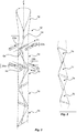
- Fig. 3 shows a series of packages 1a-b manufactured in an alternating manner in accordance with the description herein.
- Fig. 4 is a schematic representation of a jaw system, where the first and second pair of sealing jaws 22a-b, 24a-b are arranged to provide transversal seals to a tube 12, e.g. by having all jaws 22a-b, 24a-b arranged at the same longitudinal position of the tube 12.
- This jaw system can thus be realized by using two pairs of chain assemblies, on which many jaws can be mounted. This is the typical setup that is used for the filling machines that manufacture Tetra Classic® packages.
- the jaw system can also be realized by having only two pairs of jaws which are driven by some drive means, similar to what is used in the Tetra Pak A3/Flex filling machine or TBA/19 filling machine.
- each pair of jaws 22a-b, 24a-b in making a transversal seal 6a, 6b across the tube 12 of packaging material is making, in the same operation, the top transversal end for one of the individual packages 1a, 1b and the bottom transversal end for another of the individual packages 1b, 1a, the tube 12 of packaging material being subsequently cut along approximately the median line of each transversal seal 6a, 6b by any suitable means, not shown, to separate the strip material into individual packages 1a, 1b.
- Fig. 2 it may appear that the tube 12 of packaging material is stationary and the jaws 22a-b, 24a-b make the transversal sealings 6a, 6b at different positions. This is not the case in normal production, however, where each sealing jaw 22a-b, 24a-b makes contact with the tube 12 of packaging material at an almost constant position (position along the longitudinal axis Z), and the tube 12 is then pulled down allowing for a new sealing jaw to again make a transversal seal at the same position along the longitudinal axis Z as the previous jaw.
- This pulling action of the sealing jaws 22a-b, 24a-b on the tube 12 is what feeds the web 10 of packaging material through the machine. Sometimes, additional feeding rollers are provided further upstream in the filling machine, in order to reduce the tension in the web 10.
- each sealing jaw 22a-b, 24a-b has an extension in the sealing direction, i.e. the directions Y1, Y2 indicated in Fig. 2 .
- the two sealing jaws 22a-b, 24a-b of a common pair face each other, i.e. they are arranged opposed to each other.
- the normal of each sealing jaw 22a-b, 24a-b is thus perpendicular to its associated sealing direction Y1, Y2.
- the angular distance between a first jaw 22a of the first pair of jaws and a first jaw 24a of the second pair of jaws, in Fig. 4 indicated by reference ⁇ is less than 90°, preferably between 75-80°, even more preferably 78,5°.
- the angular distance between the first jaw 22a of the first pair of jaws and a second jaw 24b of the second pair of jaws, in Fig. 4 indicated by reference ⁇ is greater than 90°, preferably between 100-105°, even more preferably 101,5°.
- the angular distance is thus measured between the normal of the respective sealing jaw 22a-b, 24a-b as indicated in Fig. 4 . It should be noted that the angular distances mentioned above are preferably measured when the jaws 22a-b, 24a-b are arranged in their sealing position, i.e. when two jaws of a common pair meet with each other.
- Fig. 5 an example of a package 1a is shown for further explaining the orientation of the transversal ends 2, 3 as provided by the sealing jaw assembly shown in Fig. 4 .
- the sealing jaws 22a-b, 24a-b are as explained earlier angled relative to each other such that a projection of the transversal end 2 into a plane being perpendicular to the longitudinal axis Z of the tube 12 is not perpendicular to a projection of the bottom transversal ends 3 in the same plane.
- the sealing jaws 22a-b, 24a-b are tilted relative a plane being perpendicular to the longitudinal axis Z of tube 12 such that the transversal ends 2, 3 extend in a direction not being perpendicular to the longitudinal extension Z of the tube 12.
- the transversal ends 2, 3 are tilted relative a plane being perpendicular to the longitudinal direction Z of the tube 12 by an angle ⁇ .
- the tilt angle ⁇ is between 15-30°, preferably between 20-25°.
- Fig. 6 an example of a package 1a is shown in cross-section.
- the transversal ends 2, 3 are non-perpendicular to each other, as indicated by the angles ⁇ , ⁇ .
- the first transversal end 2 and the second transversal end 3 are arranged in parallel planes, and a projection of the second transversal end 3 into the plane of the first transversal end 2 intersects the first transversal end 2 by an angle ⁇ being less than 90°.
- a method 100 for providing transversal seals to a tube of packaging material comprises a first step 102 of providing a first pair of opposing sealing jaws being movable relative to each other, and a second step 104 of providing a second pair of opposing sealing jaws being moveable relative to each other. Steps 102, 104 are performed such that the angular distance between a first jaw of the first pair of jaws and a first jaw of the second pair of jaws is less than 90°, and the angular distance between the first jaw of the first pair of jaws and a second jaw of the second pair of jaws is greater than 90°.
- the method 100 also comprises a third step 106 of activating said first and second pairs of sealing jaws such that the tube of packaging material is provided with transversal seals.
Landscapes
- Engineering & Computer Science (AREA)
- Mechanical Engineering (AREA)
- Chemical & Material Sciences (AREA)
- Composite Materials (AREA)
- Package Closures (AREA)
- Containers And Plastic Fillers For Packaging (AREA)
Abstract
Description
- The present invention relates to a method of providing transversal seals to a tube of packaging material, as well as a sealing jaw assembly capable of providing such transversal seals. In particular, the present invention relates to providing transversal seals in order to form irregular tetrahedral packages.
- Irregular tetrahedral packages have been suggested by the present applicant e.g. in
WO2014/154623 . In short, the irregular tetrahedral packages are produced from a tube of packaging material, preferably being configured to enclose a liquid food product. The tube is formed by reforming a flat web of packaging material to a cylindrical tube, filling the tube with a product, and transversally sealing and cutting the tube, at regular intervals, into separate packages. - For this type of packages, and as is described in the above-mentioned prior art reference, the transversal seals are provided by two separate pairs of sealing jaws. These pairs of sealing jaws are operating relative to each other such that each pair will clamp the tube in a respective plane during sealing. The sealing jaws of a plane may thus operate, i.e. perform sealing, in a plane being perpendicular to the longitudinal axis of the tube. As the tube normally extends vertically, the sealing plane is thus coinciding with a horizontal plane. These pairs of jaws can also be tilted slightly such that the transversal seals are provided at an angle relative the horizontal plane. The purpose of having the sealing jaw pairs angled relative the horizontal plane is to produce two types of irregular tetrahedral packages in an alternating manner, where one package is a mirror image of its immediately upstream and downstream package. By combining six packages, three of each type, it has been proven possible to arrange all six packages in the shape of a rectangular box, i.e. a six-face shape of which all faces are a rectangle, and of which each pair of adjacent faces meets at a right angle.
- As is evident, these types of packages may be stored and transported extremely efficient as the packages fill almost the entire space within the rectangular box.
- Although irregular tetrahedral packages can be arranged into a cube for improved storing and transport, once filled the shape of the packages may be slightly distorted. This means that perfect fit into a rectangular box may be difficult to achieve, and there is thus a need for further improving these kinds of packages.
- An object of the invention is to provide a sealing jaw assembly, a method for providing transversal seals to a tube of packaging material, and an irregular tetrahedral package overcoming the above mentioned drawbacks of prior art systems and methods.
- According to a first aspect a sealing jaw assembly for providing transversal seals to a tube of packaging material is provided. The sealing jaw assembly comprises a first pair of opposing sealing jaws being movable relative to each other to provide a first transversal seal to the tube, and a second pair of opposing sealing jaws being moveable relative to each other to provide a second transversal seal to the tube. The angular distance between a first jaw of the first pair of jaws and a first jaw of the second pair of jaws is less than 90°, and the angular distance between the first jaw of the first pair of jaws and a second jaw of the second pair of jaws is greater than 90°, whereby the angular distances are measured in a plane being perpendicular to the longitudinal axis of the tube.
- In an example, the angular distance between a first jaw of the first pair of jaws and a first jaw of the second pair of jaws is between 75-80°, preferably 78,5°, and the angular distance between the first jaw of the first pair of jaws and a second jaw of the second pair of jaws is between 100-105°, preferably 101,5°.
- The sealing jaws of the first and second pair of sealing jaws may be arranged to move relative to each other such that the sealing jaws of the first pair of sealing jaws meet in a first sealing plane during sealing, and the sealing jaws of the second pair of sealing jaws meet in a second sealing plane during sealing.
- In an example the first sealing plane is the same as the second sealing plane. In another example, the sealing plane of the first and the second sealing plane are different.
- In an example the sealing plane in which the sealing jaws of a respective pair of sealing jaws meet during sealing may be tilted relative a plane being perpendicular to the longitudinal axis of tube.
- In an example the tilting angle of the sealing plane relative a plane being perpendicular to the longitudinal axis of the tube is between 15-30°, preferably between 20-25°.
- The pairs of sealing jaws may be configured to provide induction heating of the packaging material.
- In an example the pairs of sealing jaws are configured to operate synchronous or asynchronous relative to each pair of jaws.
- According to a second aspect, a method for providing transversal seals to a tube of packaging material is provided. The method comprises providing a first pair of opposing sealing jaws being movable relative to each other, and providing a second pair of opposing sealing jaws being moveable relative to each other, wherein the angular distance between a first jaw of the first pair of jaws and a first jaw of the second pair of jaws is less than 90°, and the angular distance between the first jaw of the first pair of jaws rand a second jaw of the second pair of jaws is greater than 90°. The method further comprises activating said first and second pairs of sealing jaws for transversely sealing the tube.
- In an example the sealing jaws of the first and second pair of sealing jaws moves relative to each other such that the sealing jaws of the first pair of sealing jaws meet in a sealing plane during sealing, and the sealing jaws of the second pair of sealing jaws meet in a respective sealing plane during sealing.
- In an example the pairs of sealing jaws seal the packaging material by induction heating, or other types of heating such as ultrasound or other commonly used heating techniques for packages.
- In an example the pairs of sealing jaws move synchronous or asynchronous relative to each pair of jaws.
- Examples of the teachings herein will be described in further detail in the following with reference to the accompanying drawings which illustrate nonlimiting examples on how the examples can be reduced into practice and in which:
-
Fig. 1 is an isometric view of irregular tetrahedral packages according to an example; -
Fig. 2 is an isometric view of a tube of packaging material during production of individual irregular tetrahedral packages; -
Fig. 3 is an isometric view of a sequence of irregular tetrahedral packages; -
Fig. 4 is a top view of a sealing jaw assembly according to an example; -
Fig. 5 is an isometric view of a package according to an example; -
Fig. 6 is a cross-sectional view of a package according to an example; and -
Fig. 7 is a schematic view of a method according to an example. - The present invention relates to a new method and sealing jaw assembly for manufacturing irregular tetrahedral packages, as well as such packages. An example of
packages Fig. 1 . These are idealized packages that has flat side panels and distinct edges, but it should be understood that an actual package may deviate slightly from this ideal shape when manufactured in an actual machine. The side panels may be bulging outwardly slightly, and the edges may be slightly rounded. - In
Fig. 1 , the shownpackages 1a-b are made from a flat web of laminated packaging material, typically comprising a carton-based core, for giving certain stiffness to the package, and inner and outer polymer layers. The inner polymer layer makes the package liquid-tight and protects the carton-based core layer, and it further allows heat-sealing of the package into its final shape. The outer layer protects the carton-based core layer from the moisture coming from the environment. - In some cases, an aluminum layer can also be provided in the laminated packaging material, normally on the inside of the carton-based core layer, to protect the food product from oxygen and/or light. The aluminum layer is typically covered with an inner most polymer layer.
- The
package package 1a-b, in which the content of the package 1 will be enclosed. The package has four lateral edges, being labeled using the corners, i.e. ab, ac, bd, cd, and two end edges, ad and bc. Two end fins, 2 and 3, project from said end edges. These end fins 2, 3 form transversal ends of the package 1. The package 1 has four side panels, labeled by the corners that define them, i.e. ABC, ACD, ABD and BCD. - Each
package - As is shown in
Fig. 1 , eachpackage 1a-b is shown having a longitudinal sealing 4 extending from the firsttransversal end 2 to the secondtransversal end 3. The longitudinal sealing 4 is made during the forming of a flat web of packaging material into a tube, before the package is filled with product and is divided into individual packages, in a way that is common in form-fill-seal machines, or in aseptic filling machines of the kind manufactured by the applicant, such as Tetra Pak® A3/Flex or Tetra Pak® A1. - Each package 1 thus has a
body 5 having a tetrahedral shape formed by transversally sealing twoends - The
packages 1a-b, being defined as above, are preferably continuously formed as two different types in an alternating manner, one type being the mirror image of the second type. InFig. 1 , afirst package 1a is shown to the left, and asecond package 1b is shown to the right, having a mirrored shape to thefirst package 1a. It is possible to combine three packages, twofirst packages 1a and onesecond package 1b, into a triangular prism. Two such triangular prisms can be combined into a rectangular box. The rectangular box can be formed in two ways: 1) by combining two groups of 1a-1b-1a prisms, or 2) by combining a group of 1a-1b-1a prism with a group of 1b-1a-1b prism. In the second case, the same amount offirst type 1a andsecond type 1b packages are used. - Now, the manufacturing the packages of the invention will be described. In
Fig. 2 , a part of aweb 10 of packaging material is provided, being of the laminated type as described above. Theflat web 10 of packaging material is brought through a forming section, not shown, in which theweb 10 is formed into acylindrical tube 12 of packaging material. Anoverlap area 14, forming a longitudinal seal, is provided during the tube forming. The overlapping edges are sealed together in a way known per se, typically by heating the edges and then pressing them together. Theoverlap area 14 may be provided with a plastic strip, not shown, which is sealed to the inside surface of theoverlap area 14, and which strip protrudes from one lateral edge of theweb 10 of packaging material. This strip serves to cover the inner carton edge of the packaging material, in a way known per se, which edge may otherwise absorb the liquid food product inside thepackage - In
Fig. 2 , the arrangement shown providesfirst packages 1a andsecond packages 1b in an alternating manner from asingle tube 12 of packaging material. For this, a sealing jaw arrangement 20 is required. The sealing jaw arrangement 20 comprises at least a first pair of opposing sealingjaws transversal seal 6a to thetube 12, anda second pair of opposing sealingjaws transversal seal 6b to thetube 12. The firsttransversal seal 6a is provided such that it forms the uppertransversal end 2 of onepackage 1b, and a bottomtransversal end 3 of itsadjacent package 1a (seeFig. 1 ), while the secondtransversal seal 6b is provided such that it forms the bottomtransversal end 2 of onepackage 1a, and an uppertransversal end 2 of itsadjacent package 1b. - The sealing jaw assembly 20 is configured such that the angular distance between a
first jaw 22a of the first pair of jaws and afirst jaw 24a of the second pair of jaws, when measured in a plane being perpendicular to the longitudinal extension Z of thetube 12, is less than 90°, and the angular distance between thefirst jaw 22a of the first pair of jaws and asecond jaw 24b of the second pair of jaws, when measured in the same plane being perpendicular to the longitudinal extension Z of thetube 12, is greater than 90°. This will further be explained with respect toFig. 4 . - The sealing
jaws 22a-b, 24a-b will be operated such that they meet, during sealing, at an angle being about 22.5° in relation to a plane being perpendicular to the longitudinal axis of thetube 12 of packaging material. If the longitudinal extension Z of thetube 12 is arranged in the vertical direction, the sealingjaws 22a-b, 24a-b are tilted relative the horizontal plane when they meet during sealing. - The pairs of sealing
jaws 22a-b, 24a-b are mounted for reciprocal motion toward and away from one another, as is indicated with arrows on eachjaw 22a-b, 24a-b. The jaws of a common pair when moved toward each other act to compress and flatten thetube 12 of packaging material so as to adhere opposed interior surfaces of the packaging material together. When activated, the jaws of a common pair of sealing jaws achieve a seal of the tubular material along a seam line or sealing axis which intersects the longitudinal axis Z of thetube 12. - Adjacent pairs of
jaws 22a-b, 24a-b are so oriented that they meet and make a seal in transversal directions which are angled relative one another, i.e. the direction indicated by reference numeral Y1 is angled relative to the direction indicated by reference numeral Y2. Especially, and as will further be explained with respect toFig. 4 , the sealingjaws 22a-b of the first pair are not perpendicular to the sealingjaws 24a-b of the second pair. It should be noted that the angle between the transversal directions Y1, Y2 are measured in a plane being perpendicular to the longitudinal axis Z of thetube 12. - In order to achieve the unique irregularity of the tetrahedral shape of the
packages jaws 22a-b, 24a-b is configured to be moveable such that thejaws jaws jaws 22a-b, 24a-b meet with each other in order to provide the seal, they are oriented to lie in a plane which has a predetermined angular relationship to the length direction of thetube 12 of packaging material, so that the longitudinal axis Y1, Y2 of thetransversal sealings jaw 22a-b, 24a-b is for this purpose, when arranged in their respective operative position for providing thesealing tube 12. This will lead totransversal sealings tube 12 of packaging material. - The pairs of
jaws 22a-b, 24a-b may be spaced apart longitudinally from another, measured along the longitudinal axis Z of thetube 12 of packaging material, as indicated inFig. 2 . However, the first and second pair of sealingjaws 22a-b, 24a-b may also be arranged at the same position along the longitudinal extension of thetube 12, whereby activation of the respective pair is controlled in a manner such that when thetube 12 is fed forward (or downward inFig. 2 ), thesealings -
Fig. 3 shows a series ofpackages 1a-b manufactured in an alternating manner in accordance with the description herein. -
Fig. 4 is a schematic representation of a jaw system, where the first and second pair of sealingjaws 22a-b, 24a-b are arranged to provide transversal seals to atube 12, e.g. by having alljaws 22a-b, 24a-b arranged at the same longitudinal position of thetube 12. - This jaw system can thus be realized by using two pairs of chain assemblies, on which many jaws can be mounted. This is the typical setup that is used for the filling machines that manufacture Tetra Classic® packages. The jaw system can also be realized by having only two pairs of jaws which are driven by some drive means, similar to what is used in the Tetra Pak A3/Flex filling machine or TBA/19 filling machine.
- It will of course be understood that each pair of
jaws 22a-b, 24a-b in making atransversal seal tube 12 of packaging material is making, in the same operation, the top transversal end for one of theindividual packages individual packages tube 12 of packaging material being subsequently cut along approximately the median line of eachtransversal seal individual packages - In
Fig. 2 , it may appear that thetube 12 of packaging material is stationary and thejaws 22a-b, 24a-b make thetransversal sealings jaw 22a-b, 24a-b makes contact with thetube 12 of packaging material at an almost constant position (position along the longitudinal axis Z), and thetube 12 is then pulled down allowing for a new sealing jaw to again make a transversal seal at the same position along the longitudinal axis Z as the previous jaw. This pulling action of the sealingjaws 22a-b, 24a-b on thetube 12 is what feeds theweb 10 of packaging material through the machine. Sometimes, additional feeding rollers are provided further upstream in the filling machine, in order to reduce the tension in theweb 10. - Now returning to
Fig. 4 each sealingjaw 22a-b, 24a-b has an extension in the sealing direction, i.e. the directions Y1, Y2 indicated inFig. 2 . The two sealingjaws 22a-b, 24a-b of a common pair face each other, i.e. they are arranged opposed to each other. The normal of each sealingjaw 22a-b, 24a-b is thus perpendicular to its associated sealing direction Y1, Y2. - The angular distance between a
first jaw 22a of the first pair of jaws and afirst jaw 24a of the second pair of jaws, inFig. 4 indicated by reference α, is less than 90°, preferably between 75-80°, even more preferably 78,5°. The angular distance between thefirst jaw 22a of the first pair of jaws and asecond jaw 24b of the second pair of jaws, inFig. 4 indicated by reference β, is greater than 90°, preferably between 100-105°, even more preferably 101,5°. The angular distance is thus measured between the normal of therespective sealing jaw 22a-b, 24a-b as indicated inFig. 4 . It should be noted that the angular distances mentioned above are preferably measured when thejaws 22a-b, 24a-b are arranged in their sealing position, i.e. when two jaws of a common pair meet with each other. - In
Fig. 5 an example of apackage 1a is shown for further explaining the orientation of the transversal ends 2, 3 as provided by the sealing jaw assembly shown inFig. 4 . The sealingjaws 22a-b, 24a-b are as explained earlier angled relative to each other such that a projection of thetransversal end 2 into a plane being perpendicular to the longitudinal axis Z of thetube 12 is not perpendicular to a projection of the bottom transversal ends 3 in the same plane. Further, the sealingjaws 22a-b, 24a-b are tilted relative a plane being perpendicular to the longitudinal axis Z oftube 12 such that the transversal ends 2, 3 extend in a direction not being perpendicular to the longitudinal extension Z of thetube 12. As can be seen inFig. 5 the transversal ends 2, 3 are tilted relative a plane being perpendicular to the longitudinal direction Z of thetube 12 by an angle γ. Preferably, the tilt angle γ is between 15-30°, preferably between 20-25°. - In
Fig. 6 an example of apackage 1a is shown in cross-section. The transversal ends 2, 3 are non-perpendicular to each other, as indicated by the angles α, β. Hence, the firsttransversal end 2 and the secondtransversal end 3 are arranged in parallel planes, and a projection of the secondtransversal end 3 into the plane of the firsttransversal end 2 intersects the firsttransversal end 2 by an angle α being less than 90°. - In
Fig. 7 amethod 100 for providing transversal seals to a tube of packaging material is schematically shown. The method comprises afirst step 102 of providing a first pair of opposing sealing jaws being movable relative to each other, and asecond step 104 of providing a second pair of opposing sealing jaws being moveable relative to each other.Steps method 100 also comprises athird step 106 of activating said first and second pairs of sealing jaws such that the tube of packaging material is provided with transversal seals. - The invention has mainly been described with reference to a few examples. However, as is readily understood by a person skilled in the art, other examples than the ones disclosed above are equally possible within the scope of the invention, as defined by the appended claims.
Claims (11)
- A sealing jaw assembly for providing transversal seals to a tube of packaging material, said sealing jaw assembly comprising
a first pair of opposing sealing jaws being movable relative to each other to provide a first transversal seal to the tube, and
a second pair of opposing sealing jaws being moveable relative to each other to provide a second transversal seal to the tube, wherein
an angular distance between a first jaw of the first pair of jaws and a first jaw of the second pair of jaws is less than 90°, and an angular distance between the first jaw of the first pair of jaws and a second jaw of the second pair of jaws is greater than 90°. - The sealing jaw assembly according to claim 1, wherein the angular distance between the first jaw of the first pair of jaws and the first jaw of the second pair of jaws is between 75-80°, and the angular distance between the first jaw of the first pair of jaws and the second jaw of the second pair of jaws is between 100-105°
- The sealing jaw assembly according to claim 1 or 2, wherein the sealing jaws of the first and second pair of sealing jaws are arranged to move relative to each other such that the sealing jaws of the first pair of sealing jaws meet in a first sealing plane during sealing, and the sealing jaws of the second pair of sealing jaws meet in a second sealing plane during sealing.
- The sealing jaw assembly according to claim 3, wherein the sealing planes in which the sealing jaws of the first and second pair of sealing jaws meet during sealing is tilted at a tilt angle, relative a plane being perpendicular to a longitudinal axis of the tube.
- The sealing jaw assembly according to claim 4, wherein the tilt angle is between 15-30°.
- The sealing jaw assembly according to any one of the preceding claims, wherein said pairs of sealing jaws are configured to provide induction heating of the packaging material.
- The sealing jaw assembly according to any one of the preceding claims, wherein said pairs of sealing jaws are configured to operate synchronous or asynchronous relative to each pair of jaws.
- A method for providing transversal seals to a tube of packaging material, comprisingproviding a first pair of opposing sealing jaws being movable relative to each other, andproviding a second pair of opposing sealing jaws being moveable relative to each other, whereinan angular distance between a first jaw of the first pair of jaws and a first jaw of the second pair of jaws is less than 90°, and an angular distance between the first jaw of the first pair of jaws and a second jaw of the second pair of jaws is greater than 90°, andactivating said first and second pairs of sealing jaws for transversely sealing the tube.
- The method according to claim 8, wherein the sealing jaws of the first and second pair of sealing jaws moves relative to each other such that the sealing jaws of the first pair of sealing jaws meet in a first sealing plane during sealing, and the sealing jaws of the second pair of sealing jaws meet in a second sealing plane during sealing.
- The method according to claims 8 or 9, wherein said pairs of sealing jaws seal the packaging material by induction heating.
- The method according to any one of claims 8-10, wherein said pairs of sealing jaws move synchronous or asynchronous relative to each pair of jaws.
Applications Claiming Priority (1)
| Application Number | Priority Date | Filing Date | Title |
|---|---|---|---|
| EP16205595 | 2016-12-21 |
Publications (2)
| Publication Number | Publication Date |
|---|---|
| EP3339003A1 true EP3339003A1 (en) | 2018-06-27 |
| EP3339003B1 EP3339003B1 (en) | 2020-01-29 |
Family
ID=57583033
Family Applications (1)
| Application Number | Title | Priority Date | Filing Date |
|---|---|---|---|
| EP17205236.7A Active EP3339003B1 (en) | 2016-12-21 | 2017-12-04 | A method for providing transversal seals to a tube of packaging material, and a sealing jaw assembly |
Country Status (5)
| Country | Link |
|---|---|
| US (1) | US20200108963A1 (en) |
| EP (1) | EP3339003B1 (en) |
| JP (1) | JP7091001B2 (en) |
| CN (2) | CN207791327U (en) |
| WO (1) | WO2018114310A1 (en) |
Families Citing this family (2)
| Publication number | Priority date | Publication date | Assignee | Title |
|---|---|---|---|---|
| JP7091001B2 (en) * | 2016-12-21 | 2022-06-27 | テトラ ラバル ホールディングス アンド ファイナンス エス エイ | How to provide a lateral seal on a tube of packaging material, and a seal jaw assembly |
| US20250346381A1 (en) * | 2019-06-28 | 2025-11-13 | Alka Global Ltd | Pouch for a Food Product |
Citations (5)
| Publication number | Priority date | Publication date | Assignee | Title |
|---|---|---|---|---|
| CH248124A (en) * | 1944-08-17 | 1947-04-15 | Rausing Ruben | Process for the production, filling and closing of packaging in one continuous operation. |
| SE346284B (en) * | 1966-12-13 | 1972-07-03 | Tetra Pak Int | |
| JPH04142231A (en) * | 1990-09-21 | 1992-05-15 | Anritsu Corp | Packaging machine |
| WO2014154623A1 (en) * | 2013-03-28 | 2014-10-02 | Tetra Laval Holdings & Finance S.A. | A method of manufacturing a package, a web of packaging material, a package and a filling machine |
| WO2015019300A1 (en) * | 2013-08-07 | 2015-02-12 | Gampack S.R.L. | Machine, process, container and packaging for packing tetrahedral-shaped products |
Family Cites Families (8)
| Publication number | Priority date | Publication date | Assignee | Title |
|---|---|---|---|---|
| GB864826A (en) * | 1958-06-10 | 1961-04-06 | Erik Eskil Berglund | Improvements in and relating to tetrahedral containers and the manufacture thereof |
| US3925959A (en) * | 1967-09-22 | 1975-12-16 | Gen Foods Corp | Tetrahedral packaging means and method of making same |
| US3529397A (en) * | 1967-12-19 | 1970-09-22 | Mira Pak Inc | Method and apparatus for forming tetrahedron-shaped packages |
| GB2028253A (en) * | 1978-08-14 | 1980-03-05 | Rodrigues Ely R | Manufacture of tea bags |
| JPH03124519A (en) * | 1989-09-29 | 1991-05-28 | Kataoka Bussan Kk | Manufacture of tea bag and apparatus |
| US7036713B2 (en) * | 2001-08-03 | 2006-05-02 | Jung Min Lee | Tetrahedron/pentahedron container |
| US9238537B2 (en) * | 2013-06-10 | 2016-01-19 | Frito-Lay North America, Inc. | Method for producing multi-compartment packages |
| JP7091001B2 (en) * | 2016-12-21 | 2022-06-27 | テトラ ラバル ホールディングス アンド ファイナンス エス エイ | How to provide a lateral seal on a tube of packaging material, and a seal jaw assembly |
-
2017
- 2017-12-04 JP JP2019533322A patent/JP7091001B2/en active Active
- 2017-12-04 WO PCT/EP2017/081401 patent/WO2018114310A1/en not_active Ceased
- 2017-12-04 US US16/470,393 patent/US20200108963A1/en not_active Abandoned
- 2017-12-04 EP EP17205236.7A patent/EP3339003B1/en active Active
- 2017-12-05 CN CN201721667585.8U patent/CN207791327U/en active Active
- 2017-12-05 CN CN201711264518.6A patent/CN108298146B/en active Active
Patent Citations (5)
| Publication number | Priority date | Publication date | Assignee | Title |
|---|---|---|---|---|
| CH248124A (en) * | 1944-08-17 | 1947-04-15 | Rausing Ruben | Process for the production, filling and closing of packaging in one continuous operation. |
| SE346284B (en) * | 1966-12-13 | 1972-07-03 | Tetra Pak Int | |
| JPH04142231A (en) * | 1990-09-21 | 1992-05-15 | Anritsu Corp | Packaging machine |
| WO2014154623A1 (en) * | 2013-03-28 | 2014-10-02 | Tetra Laval Holdings & Finance S.A. | A method of manufacturing a package, a web of packaging material, a package and a filling machine |
| WO2015019300A1 (en) * | 2013-08-07 | 2015-02-12 | Gampack S.R.L. | Machine, process, container and packaging for packing tetrahedral-shaped products |
Also Published As
| Publication number | Publication date |
|---|---|
| JP7091001B2 (en) | 2022-06-27 |
| CN108298146B (en) | 2021-11-05 |
| CN108298146A (en) | 2018-07-20 |
| WO2018114310A1 (en) | 2018-06-28 |
| CN207791327U (en) | 2018-08-31 |
| JP2020501999A (en) | 2020-01-23 |
| US20200108963A1 (en) | 2020-04-09 |
| EP3339003B1 (en) | 2020-01-29 |
Similar Documents
| Publication | Publication Date | Title |
|---|---|---|
| EP0460540B1 (en) | A forming device in packaging machines | |
| US10315790B2 (en) | Method and apparatus for manufacturing a tetrahedral package | |
| CN109689506B (en) | Anvil and ultrasonic sealing device | |
| EP2445821B1 (en) | Strip splicing | |
| EP3693282B1 (en) | Ultrasonic sealing anvil and ultrasonic sealing apparatus | |
| US20170247130A1 (en) | Fill packaging method and fill packaging machine for liquid packing material | |
| EP0359057A1 (en) | A method and an arrangement for the manufacture of a laminated material strip | |
| US9688431B2 (en) | Longitudinal sealing device | |
| US10829254B2 (en) | Method and a machine for producing a sealed package | |
| EP3339003B1 (en) | A method for providing transversal seals to a tube of packaging material, and a sealing jaw assembly | |
| CN107708975A (en) | Processing for package sleeve, the especially purposes of the equipment of ultrasonic bonding and the equipment | |
| US10279542B2 (en) | Ultrasonic sealing anvil | |
| US20190077527A1 (en) | A method of operating a packaging machine | |
| EP3339220A2 (en) | Package positioning device, system and method for providing even distances between packages | |
| JP2020125142A (en) | Packaging bag | |
| EP3339197B1 (en) | A method for providing transversal seals to a tube of packaging material, and a sealing jaw assembly | |
| US12304685B2 (en) | Vertical flow-wrapper with improved corner folding | |
| CN208630992U (en) | Cutting device for cutting sheets of packaging material | |
| CN121038945A (en) | Ultrasonic sealing system and its anvil | |
| CN121175176A (en) | Ultrasonic sealing system and anvil thereof | |
| CN121152719A (en) | Ultrasonic sealing system and its anvil | |
| IT202300020940A1 (en) | INSPECTION APPARATUS FOR A CAPPING MACHINE, CAPPING MACHINE HAVING AN INSPECTION APPARATUS, PACKAGING PLANT, METHOD OF INSPECTING CAPS AND METHOD OF CAPPING |
Legal Events
| Date | Code | Title | Description |
|---|---|---|---|
| PUAI | Public reference made under article 153(3) epc to a published international application that has entered the european phase |
Free format text: ORIGINAL CODE: 0009012 |
|
| STAA | Information on the status of an ep patent application or granted ep patent |
Free format text: STATUS: THE APPLICATION HAS BEEN PUBLISHED |
|
| AK | Designated contracting states |
Kind code of ref document: A1 Designated state(s): AL AT BE BG CH CY CZ DE DK EE ES FI FR GB GR HR HU IE IS IT LI LT LU LV MC MK MT NL NO PL PT RO RS SE SI SK SM TR |
|
| AX | Request for extension of the european patent |
Extension state: BA ME |
|
| STAA | Information on the status of an ep patent application or granted ep patent |
Free format text: STATUS: REQUEST FOR EXAMINATION WAS MADE |
|
| 17P | Request for examination filed |
Effective date: 20190102 |
|
| RBV | Designated contracting states (corrected) |
Designated state(s): AL AT BE BG CH CY CZ DE DK EE ES FI FR GB GR HR HU IE IS IT LI LT LU LV MC MK MT NL NO PL PT RO RS SE SI SK SM TR |
|
| GRAP | Despatch of communication of intention to grant a patent |
Free format text: ORIGINAL CODE: EPIDOSNIGR1 |
|
| STAA | Information on the status of an ep patent application or granted ep patent |
Free format text: STATUS: GRANT OF PATENT IS INTENDED |
|
| RIC1 | Information provided on ipc code assigned before grant |
Ipc: B65B 9/20 20120101ALI20190509BHEP Ipc: B65D 75/50 20060101ALI20190509BHEP Ipc: B29C 65/00 20060101AFI20190509BHEP Ipc: B65B 9/12 20060101ALI20190509BHEP Ipc: B65B 51/30 20060101ALI20190509BHEP Ipc: B31B 70/00 20170101ALI20190509BHEP |
|
| INTG | Intention to grant announced |
Effective date: 20190603 |
|
| GRAJ | Information related to disapproval of communication of intention to grant by the applicant or resumption of examination proceedings by the epo deleted |
Free format text: ORIGINAL CODE: EPIDOSDIGR1 |
|
| STAA | Information on the status of an ep patent application or granted ep patent |
Free format text: STATUS: REQUEST FOR EXAMINATION WAS MADE |
|
| GRAP | Despatch of communication of intention to grant a patent |
Free format text: ORIGINAL CODE: EPIDOSNIGR1 |
|
| STAA | Information on the status of an ep patent application or granted ep patent |
Free format text: STATUS: GRANT OF PATENT IS INTENDED |
|
| GRAS | Grant fee paid |
Free format text: ORIGINAL CODE: EPIDOSNIGR3 |
|
| INTC | Intention to grant announced (deleted) | ||
| INTG | Intention to grant announced |
Effective date: 20191029 |
|
| GRAA | (expected) grant |
Free format text: ORIGINAL CODE: 0009210 |
|
| STAA | Information on the status of an ep patent application or granted ep patent |
Free format text: STATUS: THE PATENT HAS BEEN GRANTED |
|
| AK | Designated contracting states |
Kind code of ref document: B1 Designated state(s): AL AT BE BG CH CY CZ DE DK EE ES FI FR GB GR HR HU IE IS IT LI LT LU LV MC MK MT NL NO PL PT RO RS SE SI SK SM TR |
|
| REG | Reference to a national code |
Ref country code: GB Ref legal event code: FG4D |
|
| REG | Reference to a national code |
Ref country code: CH Ref legal event code: EP |
|
| REG | Reference to a national code |
Ref country code: AT Ref legal event code: REF Ref document number: 1228173 Country of ref document: AT Kind code of ref document: T Effective date: 20200215 |
|
| REG | Reference to a national code |
Ref country code: IE Ref legal event code: FG4D |
|
| REG | Reference to a national code |
Ref country code: DE Ref legal event code: R096 Ref document number: 602017011160 Country of ref document: DE |
|
| REG | Reference to a national code |
Ref country code: NL Ref legal event code: MP Effective date: 20200129 |
|
| PG25 | Lapsed in a contracting state [announced via postgrant information from national office to epo] |
Ref country code: NO Free format text: LAPSE BECAUSE OF FAILURE TO SUBMIT A TRANSLATION OF THE DESCRIPTION OR TO PAY THE FEE WITHIN THE PRESCRIBED TIME-LIMIT Effective date: 20200429 Ref country code: PT Free format text: LAPSE BECAUSE OF FAILURE TO SUBMIT A TRANSLATION OF THE DESCRIPTION OR TO PAY THE FEE WITHIN THE PRESCRIBED TIME-LIMIT Effective date: 20200621 Ref country code: FI Free format text: LAPSE BECAUSE OF FAILURE TO SUBMIT A TRANSLATION OF THE DESCRIPTION OR TO PAY THE FEE WITHIN THE PRESCRIBED TIME-LIMIT Effective date: 20200129 Ref country code: RS Free format text: LAPSE BECAUSE OF FAILURE TO SUBMIT A TRANSLATION OF THE DESCRIPTION OR TO PAY THE FEE WITHIN THE PRESCRIBED TIME-LIMIT Effective date: 20200129 |
|
| REG | Reference to a national code |
Ref country code: LT Ref legal event code: MG4D |
|
| PG25 | Lapsed in a contracting state [announced via postgrant information from national office to epo] |
Ref country code: LV Free format text: LAPSE BECAUSE OF FAILURE TO SUBMIT A TRANSLATION OF THE DESCRIPTION OR TO PAY THE FEE WITHIN THE PRESCRIBED TIME-LIMIT Effective date: 20200129 Ref country code: HR Free format text: LAPSE BECAUSE OF FAILURE TO SUBMIT A TRANSLATION OF THE DESCRIPTION OR TO PAY THE FEE WITHIN THE PRESCRIBED TIME-LIMIT Effective date: 20200129 Ref country code: SE Free format text: LAPSE BECAUSE OF FAILURE TO SUBMIT A TRANSLATION OF THE DESCRIPTION OR TO PAY THE FEE WITHIN THE PRESCRIBED TIME-LIMIT Effective date: 20200129 Ref country code: GR Free format text: LAPSE BECAUSE OF FAILURE TO SUBMIT A TRANSLATION OF THE DESCRIPTION OR TO PAY THE FEE WITHIN THE PRESCRIBED TIME-LIMIT Effective date: 20200430 Ref country code: BG Free format text: LAPSE BECAUSE OF FAILURE TO SUBMIT A TRANSLATION OF THE DESCRIPTION OR TO PAY THE FEE WITHIN THE PRESCRIBED TIME-LIMIT Effective date: 20200429 Ref country code: IS Free format text: LAPSE BECAUSE OF FAILURE TO SUBMIT A TRANSLATION OF THE DESCRIPTION OR TO PAY THE FEE WITHIN THE PRESCRIBED TIME-LIMIT Effective date: 20200529 |
|
| PG25 | Lapsed in a contracting state [announced via postgrant information from national office to epo] |
Ref country code: NL Free format text: LAPSE BECAUSE OF FAILURE TO SUBMIT A TRANSLATION OF THE DESCRIPTION OR TO PAY THE FEE WITHIN THE PRESCRIBED TIME-LIMIT Effective date: 20200129 |
|
| PG25 | Lapsed in a contracting state [announced via postgrant information from national office to epo] |
Ref country code: ES Free format text: LAPSE BECAUSE OF FAILURE TO SUBMIT A TRANSLATION OF THE DESCRIPTION OR TO PAY THE FEE WITHIN THE PRESCRIBED TIME-LIMIT Effective date: 20200129 Ref country code: LT Free format text: LAPSE BECAUSE OF FAILURE TO SUBMIT A TRANSLATION OF THE DESCRIPTION OR TO PAY THE FEE WITHIN THE PRESCRIBED TIME-LIMIT Effective date: 20200129 Ref country code: SK Free format text: LAPSE BECAUSE OF FAILURE TO SUBMIT A TRANSLATION OF THE DESCRIPTION OR TO PAY THE FEE WITHIN THE PRESCRIBED TIME-LIMIT Effective date: 20200129 Ref country code: CZ Free format text: LAPSE BECAUSE OF FAILURE TO SUBMIT A TRANSLATION OF THE DESCRIPTION OR TO PAY THE FEE WITHIN THE PRESCRIBED TIME-LIMIT Effective date: 20200129 Ref country code: RO Free format text: LAPSE BECAUSE OF FAILURE TO SUBMIT A TRANSLATION OF THE DESCRIPTION OR TO PAY THE FEE WITHIN THE PRESCRIBED TIME-LIMIT Effective date: 20200129 Ref country code: DK Free format text: LAPSE BECAUSE OF FAILURE TO SUBMIT A TRANSLATION OF THE DESCRIPTION OR TO PAY THE FEE WITHIN THE PRESCRIBED TIME-LIMIT Effective date: 20200129 Ref country code: EE Free format text: LAPSE BECAUSE OF FAILURE TO SUBMIT A TRANSLATION OF THE DESCRIPTION OR TO PAY THE FEE WITHIN THE PRESCRIBED TIME-LIMIT Effective date: 20200129 Ref country code: SM Free format text: LAPSE BECAUSE OF FAILURE TO SUBMIT A TRANSLATION OF THE DESCRIPTION OR TO PAY THE FEE WITHIN THE PRESCRIBED TIME-LIMIT Effective date: 20200129 |
|
| REG | Reference to a national code |
Ref country code: DE Ref legal event code: R097 Ref document number: 602017011160 Country of ref document: DE |
|
| REG | Reference to a national code |
Ref country code: AT Ref legal event code: MK05 Ref document number: 1228173 Country of ref document: AT Kind code of ref document: T Effective date: 20200129 |
|
| PLBE | No opposition filed within time limit |
Free format text: ORIGINAL CODE: 0009261 |
|
| STAA | Information on the status of an ep patent application or granted ep patent |
Free format text: STATUS: NO OPPOSITION FILED WITHIN TIME LIMIT |
|
| 26N | No opposition filed |
Effective date: 20201030 |
|
| PG25 | Lapsed in a contracting state [announced via postgrant information from national office to epo] |
Ref country code: AT Free format text: LAPSE BECAUSE OF FAILURE TO SUBMIT A TRANSLATION OF THE DESCRIPTION OR TO PAY THE FEE WITHIN THE PRESCRIBED TIME-LIMIT Effective date: 20200129 |
|
| PG25 | Lapsed in a contracting state [announced via postgrant information from national office to epo] |
Ref country code: PL Free format text: LAPSE BECAUSE OF FAILURE TO SUBMIT A TRANSLATION OF THE DESCRIPTION OR TO PAY THE FEE WITHIN THE PRESCRIBED TIME-LIMIT Effective date: 20200129 Ref country code: SI Free format text: LAPSE BECAUSE OF FAILURE TO SUBMIT A TRANSLATION OF THE DESCRIPTION OR TO PAY THE FEE WITHIN THE PRESCRIBED TIME-LIMIT Effective date: 20200129 |
|
| REG | Reference to a national code |
Ref country code: CH Ref legal event code: PL |
|
| PG25 | Lapsed in a contracting state [announced via postgrant information from national office to epo] |
Ref country code: MC Free format text: LAPSE BECAUSE OF FAILURE TO SUBMIT A TRANSLATION OF THE DESCRIPTION OR TO PAY THE FEE WITHIN THE PRESCRIBED TIME-LIMIT Effective date: 20200129 |
|
| REG | Reference to a national code |
Ref country code: BE Ref legal event code: MM Effective date: 20201231 |
|
| PG25 | Lapsed in a contracting state [announced via postgrant information from national office to epo] |
Ref country code: LU Free format text: LAPSE BECAUSE OF NON-PAYMENT OF DUE FEES Effective date: 20201204 Ref country code: IE Free format text: LAPSE BECAUSE OF NON-PAYMENT OF DUE FEES Effective date: 20201204 Ref country code: FR Free format text: LAPSE BECAUSE OF NON-PAYMENT OF DUE FEES Effective date: 20201231 |
|
| PG25 | Lapsed in a contracting state [announced via postgrant information from national office to epo] |
Ref country code: LI Free format text: LAPSE BECAUSE OF NON-PAYMENT OF DUE FEES Effective date: 20201231 Ref country code: CH Free format text: LAPSE BECAUSE OF NON-PAYMENT OF DUE FEES Effective date: 20201231 |
|
| PG25 | Lapsed in a contracting state [announced via postgrant information from national office to epo] |
Ref country code: TR Free format text: LAPSE BECAUSE OF FAILURE TO SUBMIT A TRANSLATION OF THE DESCRIPTION OR TO PAY THE FEE WITHIN THE PRESCRIBED TIME-LIMIT Effective date: 20200129 Ref country code: MT Free format text: LAPSE BECAUSE OF FAILURE TO SUBMIT A TRANSLATION OF THE DESCRIPTION OR TO PAY THE FEE WITHIN THE PRESCRIBED TIME-LIMIT Effective date: 20200129 Ref country code: CY Free format text: LAPSE BECAUSE OF FAILURE TO SUBMIT A TRANSLATION OF THE DESCRIPTION OR TO PAY THE FEE WITHIN THE PRESCRIBED TIME-LIMIT Effective date: 20200129 |
|
| PG25 | Lapsed in a contracting state [announced via postgrant information from national office to epo] |
Ref country code: MK Free format text: LAPSE BECAUSE OF FAILURE TO SUBMIT A TRANSLATION OF THE DESCRIPTION OR TO PAY THE FEE WITHIN THE PRESCRIBED TIME-LIMIT Effective date: 20200129 Ref country code: AL Free format text: LAPSE BECAUSE OF FAILURE TO SUBMIT A TRANSLATION OF THE DESCRIPTION OR TO PAY THE FEE WITHIN THE PRESCRIBED TIME-LIMIT Effective date: 20200129 |
|
| PG25 | Lapsed in a contracting state [announced via postgrant information from national office to epo] |
Ref country code: BE Free format text: LAPSE BECAUSE OF NON-PAYMENT OF DUE FEES Effective date: 20201231 |
|
| GBPC | Gb: european patent ceased through non-payment of renewal fee |
Effective date: 20211204 |
|
| PG25 | Lapsed in a contracting state [announced via postgrant information from national office to epo] |
Ref country code: GB Free format text: LAPSE BECAUSE OF NON-PAYMENT OF DUE FEES Effective date: 20211204 |
|
| P01 | Opt-out of the competence of the unified patent court (upc) registered |
Effective date: 20230426 |
|
| PGFP | Annual fee paid to national office [announced via postgrant information from national office to epo] |
Ref country code: IT Payment date: 20251218 Year of fee payment: 9 |
|
| PGFP | Annual fee paid to national office [announced via postgrant information from national office to epo] |
Ref country code: DE Payment date: 20251229 Year of fee payment: 9 |