EP3338991A1 - System for injection molding and mold base therefor - Google Patents
System for injection molding and mold base therefor Download PDFInfo
- Publication number
- EP3338991A1 EP3338991A1 EP17209863.4A EP17209863A EP3338991A1 EP 3338991 A1 EP3338991 A1 EP 3338991A1 EP 17209863 A EP17209863 A EP 17209863A EP 3338991 A1 EP3338991 A1 EP 3338991A1
- Authority
- EP
- European Patent Office
- Prior art keywords
- mold base
- manifold
- bridge
- bridge manifold
- mold
- Prior art date
- Legal status (The legal status is an assumption and is not a legal conclusion. Google has not performed a legal analysis and makes no representation as to the accuracy of the status listed.)
- Granted
Links
Images


Classifications
-
- B—PERFORMING OPERATIONS; TRANSPORTING
- B29—WORKING OF PLASTICS; WORKING OF SUBSTANCES IN A PLASTIC STATE IN GENERAL
- B29C—SHAPING OR JOINING OF PLASTICS; SHAPING OF MATERIAL IN A PLASTIC STATE, NOT OTHERWISE PROVIDED FOR; AFTER-TREATMENT OF THE SHAPED PRODUCTS, e.g. REPAIRING
- B29C45/00—Injection moulding, i.e. forcing the required volume of moulding material through a nozzle into a closed mould; Apparatus therefor
- B29C45/17—Component parts, details or accessories; Auxiliary operations
- B29C45/26—Moulds
- B29C45/27—Sprue channels ; Runner channels or runner nozzles
- B29C45/2701—Details not specific to hot or cold runner channels
- B29C45/2703—Means for controlling the runner flow, e.g. runner switches, adjustable runners or gates
-
- B—PERFORMING OPERATIONS; TRANSPORTING
- B29—WORKING OF PLASTICS; WORKING OF SUBSTANCES IN A PLASTIC STATE IN GENERAL
- B29C—SHAPING OR JOINING OF PLASTICS; SHAPING OF MATERIAL IN A PLASTIC STATE, NOT OTHERWISE PROVIDED FOR; AFTER-TREATMENT OF THE SHAPED PRODUCTS, e.g. REPAIRING
- B29C45/00—Injection moulding, i.e. forcing the required volume of moulding material through a nozzle into a closed mould; Apparatus therefor
- B29C45/17—Component parts, details or accessories; Auxiliary operations
- B29C45/26—Moulds
- B29C45/2673—Moulds with exchangeable mould parts, e.g. cassette moulds
- B29C45/2675—Mounting of exchangeable mould inserts
-
- B—PERFORMING OPERATIONS; TRANSPORTING
- B29—WORKING OF PLASTICS; WORKING OF SUBSTANCES IN A PLASTIC STATE IN GENERAL
- B29C—SHAPING OR JOINING OF PLASTICS; SHAPING OF MATERIAL IN A PLASTIC STATE, NOT OTHERWISE PROVIDED FOR; AFTER-TREATMENT OF THE SHAPED PRODUCTS, e.g. REPAIRING
- B29C45/00—Injection moulding, i.e. forcing the required volume of moulding material through a nozzle into a closed mould; Apparatus therefor
- B29C45/17—Component parts, details or accessories; Auxiliary operations
- B29C45/26—Moulds
- B29C45/27—Sprue channels ; Runner channels or runner nozzles
- B29C45/2725—Manifolds
-
- B—PERFORMING OPERATIONS; TRANSPORTING
- B29—WORKING OF PLASTICS; WORKING OF SUBSTANCES IN A PLASTIC STATE IN GENERAL
- B29C—SHAPING OR JOINING OF PLASTICS; SHAPING OF MATERIAL IN A PLASTIC STATE, NOT OTHERWISE PROVIDED FOR; AFTER-TREATMENT OF THE SHAPED PRODUCTS, e.g. REPAIRING
- B29C45/00—Injection moulding, i.e. forcing the required volume of moulding material through a nozzle into a closed mould; Apparatus therefor
- B29C45/17—Component parts, details or accessories; Auxiliary operations
- B29C45/40—Removing or ejecting moulded articles
- B29C45/4005—Ejector constructions; Ejector operating mechanisms
-
- B—PERFORMING OPERATIONS; TRANSPORTING
- B29—WORKING OF PLASTICS; WORKING OF SUBSTANCES IN A PLASTIC STATE IN GENERAL
- B29C—SHAPING OR JOINING OF PLASTICS; SHAPING OF MATERIAL IN A PLASTIC STATE, NOT OTHERWISE PROVIDED FOR; AFTER-TREATMENT OF THE SHAPED PRODUCTS, e.g. REPAIRING
- B29C45/00—Injection moulding, i.e. forcing the required volume of moulding material through a nozzle into a closed mould; Apparatus therefor
- B29C45/17—Component parts, details or accessories; Auxiliary operations
- B29C45/26—Moulds
- B29C45/27—Sprue channels ; Runner channels or runner nozzles
- B29C45/2701—Details not specific to hot or cold runner channels
- B29C2045/2722—Nozzles or runner channels provided with a pressure sensor
-
- B—PERFORMING OPERATIONS; TRANSPORTING
- B29—WORKING OF PLASTICS; WORKING OF SUBSTANCES IN A PLASTIC STATE IN GENERAL
- B29C—SHAPING OR JOINING OF PLASTICS; SHAPING OF MATERIAL IN A PLASTIC STATE, NOT OTHERWISE PROVIDED FOR; AFTER-TREATMENT OF THE SHAPED PRODUCTS, e.g. REPAIRING
- B29C2945/00—Indexing scheme relating to injection moulding, i.e. forcing the required volume of moulding material through a nozzle into a closed mould
- B29C2945/76—Measuring, controlling or regulating
- B29C2945/76177—Location of measurement
- B29C2945/76254—Mould
- B29C2945/76257—Mould cavity
-
- B—PERFORMING OPERATIONS; TRANSPORTING
- B29—WORKING OF PLASTICS; WORKING OF SUBSTANCES IN A PLASTIC STATE IN GENERAL
- B29C—SHAPING OR JOINING OF PLASTICS; SHAPING OF MATERIAL IN A PLASTIC STATE, NOT OTHERWISE PROVIDED FOR; AFTER-TREATMENT OF THE SHAPED PRODUCTS, e.g. REPAIRING
- B29C45/00—Injection moulding, i.e. forcing the required volume of moulding material through a nozzle into a closed mould; Apparatus therefor
- B29C45/17—Component parts, details or accessories; Auxiliary operations
- B29C45/26—Moulds
- B29C45/2673—Moulds with exchangeable mould parts, e.g. cassette moulds
Definitions
- the present invention relates to a system for injection molding of plastic parts, in particular for automotive body and/or structure components, preferably for baffle and/or reinforcing structures as well as a corresponding mold base and method.
- US 2003/0122272 A1 describes an injection molding apparatus comprising a mold with a stationary mold member and a moveable mold member. Molten material flows into cavities via inlets. Valve gates are used to open or close the inlets. A controller closes one valve gate when another valve gate is opened.
- WO 02/036324 A1 discloses different embodiments for the injection of pressurised materials through a distribution system.
- material flow is controlled at a point upstream of two or more nozzles leading to two or more gates.
- a controller which adjusts the position of a valve pin in order to regulate the material flow through a runner within a manifold, and likewise adjusts the position of a valve pin to regulate the material flow through another runner. Via both runners, a cavity portion is filled.
- a controller varies a position of the valve pins over time to match target pressure profiles respectively corresponding thereto.
- US 2009/0324771 A1 discloses a hot runner system of modular construction for injection molding.
- US 2004/0076703 A1 discloses a modular system for molds of injection molding machines.
- a mold base for a system for injection molding of plastic parts, in particular for automotive body and/or structure components, preferable for baffle and/or reinforcing structures comprises at least one (first) bridge manifold (main manifold) with at least a first and a second bridge manifold opening for feeding material to at least a first and a second sub-manifold of at least one mold insert assembly and at least a first and a second control valve, wherein the first control valve is provided and configured for controlling the material feed through the first bridge manifold opening and the second control valve is provided and configured for controlling the material feed through the second bridge manifold opening.
- a system for injection molding of plastic parts in particular for automotive body and/or structure components, preferable for baffle and/or reinforcing structures, comprises a mold base as described above and at least one mold insert assembly having at least one sub-manifold being connectable or connected to at least one of the first or second bridge manifold openings.
- a core idea of the invention is to provide a modular solution that allows for rapid changing of a mold insert assembly.
- An important feature of the invention is the first and second control valves which allow to control (in particular balance) for example flow and/or pressure from one sub-manifold to another sub-manifold.
- Existing technology provides (only) a control from gate to gate (i.e. from cavity to cavity).
- the tooling costs can be reduced, in particular by reducing the number of components the mold manufacturer is required to build.
- the material to be molded can be changed (with high flexibility) while maintaining low part costs associated with family molds. According to the invention, a high flexibility and cost reduction compared to current technology can be achieved. Tooling costs can be reduced.
- the mold insert assembly may require only ejector plates, ejectors, a core block, a cavity block and a sub-manifold.
- the mold base may comprise servo (driven) valves at each connection of the bridge manifold in order to control plastic flow and pressure. A valve position may be controlled via time, pressure or both.
- Different mold insert assemblies may be inserted into a universal mold base.
- Such universal mold base may contain (on the A-Side) for example hot runner bridges and/or servo-driven valve gates (within transfer connections where the bridge manifold meets the sub-manifolds).
- a control of the material feed means in particular that (for a given condition), the respective control valve may be controlled so that at least two different flow rates above zero, preferably at least five different flow rates above zero, further preferably at least ten different flow rates above zero and/or at least two different fluid pressures, preferably at least three different fluid pressures, further preferably at least five different fluid pressures can be controlled.
- Pressure and/or flow rate may be continuously controllable or in discrete intervals, preferably in at least two, further preferably at least five, further preferably at least ten steps.
- the mold base may comprise at least one further (second) bridge manifold with at least a third and a fourth bridge manifold opening for feeding material to at least a third and a fourth sub-manifold of at least one mold insert assembly and at least a third and a forth control valve, wherein the third control valve is provided and configured for controlling the material feed through the third bridge manifold opening and the fourth control valve is provided and configured for controlling the material feed through the fourth bridge manifold opening.
- the first and/or second bridge manifold is formed by a hot runner bridge.
- the above (and below) described mold base and the above (and below) described system may be a hot runner mold base or a hot runner system, respectively.
- at least one heating device is provided for heating the hot runner bridge so that the material in the hot runner bridge may be kept in a molten state (during the injection molding process). Thereby, material can be saved.
- the first and/or second bridge manifold may be of a one-piece structure (not necessarily, though, monolithic). Preferably, the first and second bridge manifold are separated from each other (in particular not being formed by the same, coherent structure).
- the first and/or second sub-manifold may be structurally separated with respect to the first bridge manifold, in particular meaning that they are connected or connectable (as separate parts) to the corresponding first and/or second opening(s) of the first bridge manifold.
- a third and fourth sub-manifold may be structurally separated with respect to the second bridge manifold, in particular meaning that they are connected or connectable (as separate parts) to the corresponding third and/or fourth opening(s) of the second bridge manifold.
- First and/or second and/or third and/or fourth sub-manifolds may be of a one-piece structure (not necessarily, though, monolithic).
- First and/or second bridge manifolds may comprise at least two arms (e.g. exactly two arms) which lead to the corresponding openings to the corresponding sub-manifolds.
- the first and/or second and/or third and/or fourth sub-manifolds may comprise at least two, preferably at least three, further preferably at least four (e.g. exactly four) arms leading to their nozzles or sprouts, respectively.
- At least one (further preferably several of or all of) the first and second control valves of the first bridge manifold and the third and fourth control valves of the second bridge manifold may be an electrically driven valve and/or a continuously adjustable valve, in particular a proportional valve or a servo valve, or a discretely (e.g. with at least two different or at least five different values above zero) adjustable valve.
- servo (driven) valves or valve gates respectively
- a control of the respective control valve may be an open-loop or a, preferably, closed-loop control.
- At least one of the (preferably several of, further preferably all of) first and second control valves of the first bridge manifold and, optionally, the third and fourth control valves of the second bridge manifold may be controllable or controlled via time and/or pressure, in particular a pressure within the bridge manifold and/or a pressure in at least one of the sub-manifolds.
- At least one pressure determining means in particular pressure sensor, may be provided, for determining (sensing) a pressure within the bridge manifold and/or a pressure in at least one of the sub-manifolds.
- a pressure transducer may be provided (within the bridge manifold and/or one of the sub-manifolds) that may provide real time pressure readings to a controller system.
- a controller may be provided which may open and close the control valves (preferably in real time).
- the controller may control the material flow dependent on pressure readings and/or any input from an operator or other device. Consequently, improved cavity pressure conditions can be obtained. This may result in increased part quality, in particular by reducing the possibility for flashes or shots.
- a control function as explained above may also provide a certain level of protection for the mold itself. For example, in the event of a double shot, a pressure spike outside of predetermined limits may be sensed so that a corresponding valve (gate) may be immediately closed, thereby reducing the possibility of mold damage that may be the consequence of excessive cavity pressure.
- the mold base may form a frame for receiving at least one (preferably at least two or more) mold insert assembly (assemblies). Thereby, mounting and changing of one or more mold inserts is possible. Tooling costs are reduced.
- the mold base may comprise an A-Side assembly, preferably comprising the first and (optional) second bridge manifold and a clamp member, in particular clamp plate and/or a cavity mounting member, in particular cavity mounting plate.
- the mold base may comprise a B-Side assembly, preferably comprising a clamp member, in particular a clamp plate and/or a B-Side mounting member, in particular B-Side mounting plate, and/or an ejector supporting member, in particular ejector frame.
- A-Side refers to the side of the mold base from which the molten plastic is injected into the mold.
- the B-Side refers to the other side of the mold base. Preferably, from the B-Side the molded plastic part is ejected.
- At least one of (preferably several of, in particular all of) the mold insert assemblies may comprise at least one ejector and/or at least one ejector plate and/or at least one core member, in particular core block, preferably with a plurality of core structures, and/or at least one cavity member, in particular cavity block, preferably with a plurality of cavities.
- the core member may comprise at least one (in particular two or more) removable insert(s) having at least one (in particular two or more) core structure(s).
- the cavity member may comprise at least one (preferably two or more) removable insert(s) having at least one (preferably two or more) cavity (cavities). This further improves the flexibility of the injection molding system.
- the mold may define (in a closed state) a plurality of at least two, preferably at least four, further preferably at least 10 (separate) cavities to be filled.
- each (injection) nozzle of at least one sub-manifold are configured to fill a (separate particular) cavity.
- two or more nozzles of the same sub-manifold may fill the same cavity.
- a method of injection molding of plastic parts comprising the steps of providing the system above and of controlling, in particular balancing, the flow of material through the first and second bridge manifold openings via the first and second control valve.
- the plastic material may be expandable, in particular foamable, and/or may be or may comprise polymeric material.
- the expansion (foaming) may be triggered by heat application.
- the base mold and/or the system is preferably used for molding of expandable acoustic baffles in particular for the automotive industry.
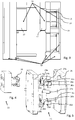
- Figs. 1 to 3 illustrate an embodiment of a system for injection molding.
- the system comprises a mold base 10 and at least one (in Figs. 1 to 3 , only one is shown) mold insert assembly 11.
- the mold insert assembly 11 comprises a core block 12 (see Fig. 3 ), a cavity block 13, an ejector plate 14, ejectors 15 and (see Fig. 4 , showing an A side assembly 22 of the mold insert assembly) a sub-manifold 16.
- Fig. 7 shows the mold insert assembly 11 with all surfaces transparent in a side view.
- the material to be fed is transported to (in this case four) sprouts 17 each having a nozzle 18 at their distal ends. From the nozzle, material is fed into a corresponding cavity 19 being formed by a cavity 20 in the cavity block and a core structure 21 in the core block.
- the injection molded parts in the cavities 19 can be ejected by the ejectors 15.
- Fig. 5 shows an A-Side assembly 23 of the mold base 11.
- the A-Side assembly 23 comprises a cavity mounting plate 24, a (stationary) clamp plate 25 and (in the present case two) bridge manifolds 26a and 26b.
- the bridge manifolds 26a, 26b comprise a material feed interface 27a, 27b, transfer bushings 28a, 28b, 28c and 28d, defining bridge manifold openings 29a, 29b, 29c and 29d and (servo-driven) valve gates 30a, 30b, 30c and 30d through which (servo) valves within the bridge manifold can be controlled in order to control pressure and/or flow of the material in the direction of openings 29a, 29b, 29c and 29d.
- the location of the (servo) valves is indicated by 31a, 31b, 31c and 31d.
- Fig. 6 shows a B-Side assembly 33 of the mold base 10 having a B-Side clamp plate 34, a B-side mounting structure 38, an ejector frame 35 and ejector guides 36. Moreover, Fig. 6 shows a B-Side assembly 37 of the mold insert assembly 11.
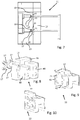
- Figs. 8 to 10 show a further embodiment of an A-Side assembly 22 of mold insert assembly 11.
- the cavity block 13 comprises a cavity block shoe 39 in which (in the present case two) cavity block inserts 40 can be inserted and removed (and be replaced by different cavity block inserts 40).
- the core block 12 comprises a core block shoe 41 and (in the present case two) core block inserts 42 which can be inserted and be removed (and be replaced with different core block inserts 42) in/from the core block shoe 41.
- the cavity block inserts 40 comprise the mold cavities.
- the core block inserts 42 comprise the mold cores.
Landscapes
- Engineering & Computer Science (AREA)
- Manufacturing & Machinery (AREA)
- Mechanical Engineering (AREA)
- Moulds For Moulding Plastics Or The Like (AREA)
- Injection Moulding Of Plastics Or The Like (AREA)
Abstract
Description
- The present invention relates to a system for injection molding of plastic parts, in particular for automotive body and/or structure components, preferably for baffle and/or reinforcing structures as well as a corresponding mold base and method.
-
US 2003/0122272 A1 describes an injection molding apparatus comprising a mold with a stationary mold member and a moveable mold member. Molten material flows into cavities via inlets. Valve gates are used to open or close the inlets. A controller closes one valve gate when another valve gate is opened. -
WO 02/036324 A1 -
US 2009/0324771 A1 discloses a hot runner system of modular construction for injection molding.US 2004/0076703 A1 discloses a modular system for molds of injection molding machines. - In order to reduce tooling costs and mold change time, several approaches for quick change mold systems have been developed. Usually such systems focus on single shot type molds. Moreover, it is generally known to control, in particular balance, plastic flow and pressure from gate to gate (whereby gate means the portion from which the plastic flow emerges into the corresponding cavity, e.g. from a sprout). Existing two-shot mold designs and constructions involve comparatively high tooling costs. Moreover, known solutions are limited regarding the flexibility in use. Once tooled, all parts within a larger family mold must run with the same material.
- It is an object of the present invention to provide a flexible and cost-saving, in particular with respect to tooling costs, system for injection molding of plastic parts, in particular for automotive body and/or structure components, preferably for baffle and/or reinforcing structures. Moreover, it is an object of the present invention to provide a corresponding mold base for such system and a corresponding method of injection molding of plastic parts, in particular for automotive body and/or structure components, preferable for baffle and/or reinforcing structures.
- According to a first aspect of the present invention, a mold base for a system for injection molding of plastic parts, in particular for automotive body and/or structure components, preferable for baffle and/or reinforcing structures, is proposed, wherein the mold base comprises at least one (first) bridge manifold (main manifold) with at least a first and a second bridge manifold opening for feeding material to at least a first and a second sub-manifold of at least one mold insert assembly and at least a first and a second control valve, wherein the first control valve is provided and configured for controlling the material feed through the first bridge manifold opening and the second control valve is provided and configured for controlling the material feed through the second bridge manifold opening.
- According to a further aspect of the invention, a system for injection molding of plastic parts, in particular for automotive body and/or structure components, preferable for baffle and/or reinforcing structures, comprises a mold base as described above and at least one mold insert assembly having at least one sub-manifold being connectable or connected to at least one of the first or second bridge manifold openings.
- A core idea of the invention is to provide a modular solution that allows for rapid changing of a mold insert assembly. An important feature of the invention is the first and second control valves which allow to control (in particular balance) for example flow and/or pressure from one sub-manifold to another sub-manifold. Existing technology provides (only) a control from gate to gate (i.e. from cavity to cavity). Thereby, in particular the tooling costs can be reduced, in particular by reducing the number of components the mold manufacturer is required to build. Moreover, the material to be molded can be changed (with high flexibility) while maintaining low part costs associated with family molds. According to the invention, a high flexibility and cost reduction compared to current technology can be achieved. Tooling costs can be reduced. Costs for implementing design or material changes can be reduced. The process control can be improved. The part quality can be improved (i.e. flash and short shot defects can be reduced). The flexibility to change the pairing of parts for different programs or customers within the same tool is increased. The mold insert assembly may require only ejector plates, ejectors, a core block, a cavity block and a sub-manifold. In particular, the mold base may comprise servo (driven) valves at each connection of the bridge manifold in order to control plastic flow and pressure. A valve position may be controlled via time, pressure or both. Different mold insert assemblies may be inserted into a universal mold base. Such universal mold base may contain (on the A-Side) for example hot runner bridges and/or servo-driven valve gates (within transfer connections where the bridge manifold meets the sub-manifolds).
- A control of the material feed means in particular that (for a given condition), the respective control valve may be controlled so that at least two different flow rates above zero, preferably at least five different flow rates above zero, further preferably at least ten different flow rates above zero and/or at least two different fluid pressures, preferably at least three different fluid pressures, further preferably at least five different fluid pressures can be controlled. Pressure and/or flow rate may be continuously controllable or in discrete intervals, preferably in at least two, further preferably at least five, further preferably at least ten steps.
- The mold base may comprise at least one further (second) bridge manifold with at least a third and a fourth bridge manifold opening for feeding material to at least a third and a fourth sub-manifold of at least one mold insert assembly and at least a third and a forth control valve, wherein the third control valve is provided and configured for controlling the material feed through the third bridge manifold opening and the fourth control valve is provided and configured for controlling the material feed through the fourth bridge manifold opening. Thereby, a simple 2-shot family type tooling can be provided which enhances the flexibility for the injection molded process.
- Preferably, the first and/or second bridge manifold is formed by a hot runner bridge. In general, the above (and below) described mold base and the above (and below) described system may be a hot runner mold base or a hot runner system, respectively. In particular, at least one heating device is provided for heating the hot runner bridge so that the material in the hot runner bridge may be kept in a molten state (during the injection molding process). Thereby, material can be saved.
- The first and/or second bridge manifold may be of a one-piece structure (not necessarily, though, monolithic). Preferably, the first and second bridge manifold are separated from each other (in particular not being formed by the same, coherent structure). The first and/or second sub-manifold may be structurally separated with respect to the first bridge manifold, in particular meaning that they are connected or connectable (as separate parts) to the corresponding first and/or second opening(s) of the first bridge manifold. In addition or alternatively, a third and fourth sub-manifold may be structurally separated with respect to the second bridge manifold, in particular meaning that they are connected or connectable (as separate parts) to the corresponding third and/or fourth opening(s) of the second bridge manifold.
- First and/or second and/or third and/or fourth sub-manifolds may be of a one-piece structure (not necessarily, though, monolithic). First and/or second bridge manifolds may comprise at least two arms (e.g. exactly two arms) which lead to the corresponding openings to the corresponding sub-manifolds. Also the first and/or second and/or third and/or fourth sub-manifolds may comprise at least two, preferably at least three, further preferably at least four (e.g. exactly four) arms leading to their nozzles or sprouts, respectively.
- Preferably, at least one (further preferably several of or all of) the first and second control valves of the first bridge manifold and the third and fourth control valves of the second bridge manifold may be an electrically driven valve and/or a continuously adjustable valve, in particular a proportional valve or a servo valve, or a discretely (e.g. with at least two different or at least five different values above zero) adjustable valve. In particular, servo (driven) valves (or valve gates respectively) are provided within the (transfer) connection where the bridge manifold meets the corresponding sub-manifold. Thereby, a reliable and precise control of the material flow into the sub-manifolds can be achieved. In general, a control of the respective control valve may be an open-loop or a, preferably, closed-loop control.
- At least one of the (preferably several of, further preferably all of) first and second control valves of the first bridge manifold and, optionally, the third and fourth control valves of the second bridge manifold may be controllable or controlled via time and/or pressure, in particular a pressure within the bridge manifold and/or a pressure in at least one of the sub-manifolds. Thereby, the control (in particular balancing) of the material flow can be improved.
- At least one pressure determining means, in particular pressure sensor, may be provided, for determining (sensing) a pressure within the bridge manifold and/or a pressure in at least one of the sub-manifolds. A pressure transducer may be provided (within the bridge manifold and/or one of the sub-manifolds) that may provide real time pressure readings to a controller system.
- In general, a controller (controller system) may be provided which may open and close the control valves (preferably in real time). The controller may control the material flow dependent on pressure readings and/or any input from an operator or other device. Consequently, improved cavity pressure conditions can be obtained. This may result in increased part quality, in particular by reducing the possibility for flashes or shots. A control function as explained above may also provide a certain level of protection for the mold itself. For example, in the event of a double shot, a pressure spike outside of predetermined limits may be sensed so that a corresponding valve (gate) may be immediately closed, thereby reducing the possibility of mold damage that may be the consequence of excessive cavity pressure.
- The mold base may form a frame for receiving at least one (preferably at least two or more) mold insert assembly (assemblies). Thereby, mounting and changing of one or more mold inserts is possible. Tooling costs are reduced.
- The mold base may comprise an A-Side assembly, preferably comprising the first and (optional) second bridge manifold and a clamp member, in particular clamp plate and/or a cavity mounting member, in particular cavity mounting plate. Moreover, the mold base may comprise a B-Side assembly, preferably comprising a clamp member, in particular a clamp plate and/or a B-Side mounting member, in particular B-Side mounting plate, and/or an ejector supporting member, in particular ejector frame. Through such assemblies, mounting and changing one or more of the mold insert assemblies is realisable and fast. The term A-Side refers to the side of the mold base from which the molten plastic is injected into the mold. The B-Side refers to the other side of the mold base. Preferably, from the B-Side the molded plastic part is ejected.
- At least one of (preferably several of, in particular all of) the mold insert assemblies may comprise at least one ejector and/or at least one ejector plate and/or at least one core member, in particular core block, preferably with a plurality of core structures, and/or at least one cavity member, in particular cavity block, preferably with a plurality of cavities.
- The core member (in particular core block) may comprise at least one (in particular two or more) removable insert(s) having at least one (in particular two or more) core structure(s). The cavity member (in particular cavity block) may comprise at least one (preferably two or more) removable insert(s) having at least one (preferably two or more) cavity (cavities). This further improves the flexibility of the injection molding system.
- The mold may define (in a closed state) a plurality of at least two, preferably at least four, further preferably at least 10 (separate) cavities to be filled.
- Preferably, each (injection) nozzle of at least one sub-manifold (in particular all sub-manifolds) are configured to fill a (separate particular) cavity. Alternatively, two or more nozzles of the same sub-manifold may fill the same cavity.
- According to a further aspect of the invention, a method of injection molding of plastic parts, in particular for automotive body and/or structure components, preferably for baffle and/or reinforcing structures, is provided, comprising the steps of providing the system above and of controlling, in particular balancing, the flow of material through the first and second bridge manifold openings via the first and second control valve.
- According to another aspect of the invention, a use of the above mold base and/or the above system for injection molding of plastic parts, in particular for automotive body and/or structure components, preferably for baffle and/or reinforcing structures, is proposed.
- The plastic material may be expandable, in particular foamable, and/or may be or may comprise polymeric material. The expansion (foaming) may be triggered by heat application. The base mold and/or the system is preferably used for molding of expandable acoustic baffles in particular for the automotive industry.
- In the following, preferred embodiments of the present invention are described with reference to the drawings. These show:
- Fig. 1
- A perspective view of a first embodiment of a system for injection molding according to the invention;
- Fig. 2
- A partially exploded perspective view of the embodiment of
Fig. 1 ; - Fig. 3
- A partially exploded side view of the embodiment of
Fig. 1 ; - Fig. 4
- A partially exploded perspective view of an A-Side assembly of a mold insert assembly according to the invention;
- Fig. 5
- A partially exploded perspective view of an A-Side assembly of a mold base according to the invention;
- Fig. 6
- A perspective view of a B-Side assembly of the mold base together with a B-Side assembly of the mold insert assembly according to the invention;
- Fig. 7
- A side view of a mold insert assembly according to the invention with all surfaces being transparent;
- Fig. 8
- A partially exploded perspective view of a further embodiment of an A-Side assembly of a mold insert assembly;
- Fig. 9
- A partially exploded perspective view of a B-Side assembly of the mold insert assembly according to the invention; and
- Fig. 10
- A perspective view of the B-Side assembly according to
Fig. 9 . -
Figs. 1 to 3 illustrate an embodiment of a system for injection molding. The system comprises amold base 10 and at least one (inFigs. 1 to 3 , only one is shown)mold insert assembly 11. Themold insert assembly 11 comprises a core block 12 (seeFig. 3 ), acavity block 13, anejector plate 14,ejectors 15 and (seeFig. 4 , showing an Aside assembly 22 of the mold insert assembly) asub-manifold 16.Fig. 7 shows themold insert assembly 11 with all surfaces transparent in a side view. The material to be fed is transported to (in this case four)sprouts 17 each having anozzle 18 at their distal ends. From the nozzle, material is fed into a correspondingcavity 19 being formed by acavity 20 in the cavity block and acore structure 21 in the core block. The injection molded parts in thecavities 19 can be ejected by theejectors 15. -
Fig. 5 shows anA-Side assembly 23 of themold base 11. TheA-Side assembly 23 comprises acavity mounting plate 24, a (stationary)clamp plate 25 and (in the present case two)bridge manifolds bridge manifolds material feed interface transfer bushings bridge manifold openings valve gates openings -
Fig. 6 shows a B-Side assembly 33 of themold base 10 having a B-Side clamp plate 34, a B-side mounting structure 38, anejector frame 35 and ejector guides 36. Moreover,Fig. 6 shows a B-Side assembly 37 of themold insert assembly 11. -
Figs. 8 to 10 show a further embodiment of anA-Side assembly 22 ofmold insert assembly 11. In this case, thecavity block 13 comprises acavity block shoe 39 in which (in the present case two) cavity block inserts 40 can be inserted and removed (and be replaced by different cavity block inserts 40). Similarly, according toFigs. 9 and 10 showing the B-Side assembly 37 ofmold insert assembly 11, thecore block 12 comprises acore block shoe 41 and (in the present case two) core block inserts 42 which can be inserted and be removed (and be replaced with different core block inserts 42) in/from thecore block shoe 41. The cavity block inserts 40 comprise the mold cavities. The core block inserts 42 comprise the mold cores. -
- 10
- Mold base
- 11
- Mold insert assembly
- 12
- Core block
- 13
- Cavity block
- 14
- Ejector plate
- 15
- Ejector
- 16
- Sub-manifold
- 17
- Sprout
- 18
- Nozzle
- 19
- Cavity
- 20
- Cavity
- 21
- Core structure
- 22
- A side assembly of the mold insert assembly
- 23
- A-Side assembly
- 24
- Cavity mounting plate
- 25
- Clamp plate
- 26a
- First bridge manifold
- 27a
- Second bridge manifold
- 27a
- Material feed interface
- 27b
- Material feed interface
- 28a
- Bushing
- 28b
- Bushing
- 28c
- Bushing
- 28d
- Bushing
- 29a
- Bridge manifold opening
- 29b
- Bridge manifold opening
- 29c
- Bridge manifold opening
- 29d
- Bridge manifold opening
- 30a
- Valve gate
- 30b
- Valve gate
- 30c
- Valve gate
- 30d
- Valve gate
- 31a
- Valve
- 31b
- Valve
- 31c
- Valve
- 31d
- Valve
- 33
- B-Side assembly
- 34
- Clamp plate
- 35
- Ejector frame
- 36
- Ejector guide
- 37
- B-Side assembly
- 38
- B-side mounting structure
- 39
- Cavity block shoe
- 40
- Cavity block insert
- 41
- Core block shoe
- 42
- Core block insert
Claims (15)
- A mold base (10) for a system for injection molding of plastic parts, in particular for automotive body and/or structure components, preferably for baffle and/or reinforcing structures, comprising
at least one, namely first, bridge manifold (26a) with at least a first (29a) and a second (29b) bridge manifold opening for feeding material to at least a first (16) and a second sub-manifold of at least one mold insert assembly (11) and
at least a first (31a) and a second (31b) control valve, wherein the first control valve (31a) is provided and configured for controlling the material feed through the first bridge manifold opening (29a) and the second control valve (31b) is provided and configured for controlling the material feed through the second bridge manifold opening (29b). - The mold base (10) of claim 1, characterised by at least one further, namely second, bridge manifold (29b) with at least a third (29c) and a fourth (29d) bridge manifold opening for feeding material to at least a third and a fourth sub-manifold of at least one mold insert assembly and at least a third (31c) and a fourth (31d) control valve, wherein the third control valve (31c) is provided and configured for controlling the material feed through the first bridge manifold opening (29a) and the fourth control valve (31d) is provided and configured for controlling the material feed through the fourth bridge manifold opening (29d).
- The mold base (10) of one of the claims 1 or 2, characterised in that the first (26a) and/or second (26b) bridge manifold is formed by a hot runner bridge (26a, 26b).
- The mold base (10) of one of the preceding claims, characterised in that at least one of the first (31a) and second (31b) control valves of the first bridge manifold (26a) and, optionally, the third (31c) and fourth (31d) control valves of the second bridge manifold (26b) is an electrically driven valve and/or a continuously adjustable valve, in particular a proportional valve or a servo valve, or a discretely adjustable valve.
- The mold base (10) of one of the preceding claims, characterised in that at least one of the first (31a) and second (31b) control valves of the first bridge manifold (26a) and, optionally, the third (31c) and fourth (31d) control valves of the second bridge manifold (26b) are controllable or controlled via time and/or pressure, in particular a pressure within the bridge manifold (26a, 26b) and/or a pressure in at least one of the sub-manifolds (16).
- The mold base (10) of one of the preceding claims, characterised by at least one pressure determining means, in particular pressure sensor, for determining a pressure within the bridge manifold (26a, 26b) and/or a pressure in at least one of the sub-manifolds (16).
- The mold base (10) of one of the preceding claims, characterised in that the mold base (10) forms a frame for receiving at least one mold insert assembly (11).
- The mold base (10) of one of the preceding claims, characterised in that the mold base (10) comprises an A side assembly (23), preferably comprising the first (26a) and optional second (26b) bridge manifold, and/or a clamp member, in particular clamp plate (25) and/or a cavity mounting structure, in particular cavity mounting plate (24).
- The mold base (10) of one of the preceding claims, characterised in that the mold base (10) comprises a B side assembly (33), preferably comprising a clamp member, in particular clamp plate (34) and/or a B side mounting structure (38), in particular B side mounting plate, and/or an ejector supporting member, in particular ejector frame (35).
- A system for injection molding of plastic parts, in particular for automotive body and/or structure components, preferably for baffle and/or reinforcing structures, comprising
a mold base (10) of one of the preceding claims and
at least one mold insert assembly (11) having at least one sub-manifold (16) being connectable or connected to at least one of the first (29a) or second (29b) bridge manifold openings. - The system of claim 10, characterised in that
the mold insert assembly (11) comprises at least one ejector (15) and/or at least one ejector plate (14) and/or at least one core member, in particular core block (12), preferably with a plurality of core structures (21), and/or at least one cavity member, in particular cavity block (13), preferably with a plurality of cavities (19). - The system of claim 11, characterised in that
the core member, in particular core block (12), comprises at least one removable insert (42) having at least one core structure (21). - The system of claim 11 or 12, characterised in that
the cavity member, in particular cavity block (13), comprises at least one removable insert (40) having at least one cavity (19). - A method of injection molding of plastic parts, in particular for automotive body and/or structure components, preferably for baffle and/or reinforcing structures, comprising the steps of providing a system of one of the claims 10 to 13 and controlling, in particular balancing, the flow of material through the first (29a) and second (29b) bridge manifold opening via the first (31a) and second (31b) control valve.
- A use of a mold base (11) of one of the claims 1 to 9 and/or a system of one of the claims 10 to 13 for injection molding of plastic parts, in particular for automotive body and/or structure components, preferably for baffle and/or reinforcing structures.
Applications Claiming Priority (1)
| Application Number | Priority Date | Filing Date | Title |
|---|---|---|---|
| EP16206845 | 2016-12-23 |
Publications (2)
| Publication Number | Publication Date |
|---|---|
| EP3338991A1 true EP3338991A1 (en) | 2018-06-27 |
| EP3338991B1 EP3338991B1 (en) | 2022-08-17 |
Family
ID=57609800
Family Applications (1)
| Application Number | Title | Priority Date | Filing Date |
|---|---|---|---|
| EP17209863.4A Active EP3338991B1 (en) | 2016-12-23 | 2017-12-21 | System for injection molding, method and use |
Country Status (3)
| Country | Link |
|---|---|
| US (1) | US11097458B2 (en) |
| EP (1) | EP3338991B1 (en) |
| ES (1) | ES2925575T3 (en) |
Cited By (2)
| Publication number | Priority date | Publication date | Assignee | Title |
|---|---|---|---|---|
| KR20220095809A (en) * | 2020-12-30 | 2022-07-07 | 주식회사 동희산업 | Baffle for fuel tank of vehicle |
| KR20220095808A (en) * | 2020-12-30 | 2022-07-07 | 주식회사 동희산업 | Baffle for fuel tank of vehicle |
Families Citing this family (2)
| Publication number | Priority date | Publication date | Assignee | Title |
|---|---|---|---|---|
| US10850438B2 (en) * | 2016-02-22 | 2020-12-01 | The Japan Steel Works, Ltd. | Injection device provided with flow path switching block |
| US11097458B2 (en) | 2016-12-23 | 2021-08-24 | Sika Technology Ag | System for injection molding and mold base therefor |
Citations (7)
| Publication number | Priority date | Publication date | Assignee | Title |
|---|---|---|---|---|
| EP1142686A1 (en) * | 1999-11-19 | 2001-10-10 | Dynisco Hotrunners, Inc. | Apparatus and method for proportionally controlling fluid delivery to readily replaceable mold inserts |
| WO2002036324A1 (en) | 2000-10-30 | 2002-05-10 | Synventive Molding Solutions, Inc. | Controlled injection using manifold having multiple feed channels |
| US20030122272A1 (en) | 2002-01-03 | 2003-07-03 | Mitsubishi Heavy Industries Injection Molding Machinery, Inc. | Method and apparatus for injection molding |
| US20040076703A1 (en) | 2002-10-11 | 2004-04-22 | Liteco S.R.L. | Standardised modular system for moulds of injection moulding machines |
| WO2009026667A1 (en) * | 2007-08-24 | 2009-03-05 | Husky Injection Molding Systems Ltd. | An apparatus for controlling melt flow in a melt distribution network |
| US20090324771A1 (en) | 2008-06-30 | 2009-12-31 | Caterpillar Inc. | Modular injection molding hot runner system |
| US11097458B2 (en) | 2016-12-23 | 2021-08-24 | Sika Technology Ag | System for injection molding and mold base therefor |
-
2017
- 2017-12-20 US US15/848,966 patent/US11097458B2/en active Active
- 2017-12-21 ES ES17209863T patent/ES2925575T3/en active Active
- 2017-12-21 EP EP17209863.4A patent/EP3338991B1/en active Active
Patent Citations (7)
| Publication number | Priority date | Publication date | Assignee | Title |
|---|---|---|---|---|
| EP1142686A1 (en) * | 1999-11-19 | 2001-10-10 | Dynisco Hotrunners, Inc. | Apparatus and method for proportionally controlling fluid delivery to readily replaceable mold inserts |
| WO2002036324A1 (en) | 2000-10-30 | 2002-05-10 | Synventive Molding Solutions, Inc. | Controlled injection using manifold having multiple feed channels |
| US20030122272A1 (en) | 2002-01-03 | 2003-07-03 | Mitsubishi Heavy Industries Injection Molding Machinery, Inc. | Method and apparatus for injection molding |
| US20040076703A1 (en) | 2002-10-11 | 2004-04-22 | Liteco S.R.L. | Standardised modular system for moulds of injection moulding machines |
| WO2009026667A1 (en) * | 2007-08-24 | 2009-03-05 | Husky Injection Molding Systems Ltd. | An apparatus for controlling melt flow in a melt distribution network |
| US20090324771A1 (en) | 2008-06-30 | 2009-12-31 | Caterpillar Inc. | Modular injection molding hot runner system |
| US11097458B2 (en) | 2016-12-23 | 2021-08-24 | Sika Technology Ag | System for injection molding and mold base therefor |
Non-Patent Citations (1)
| Title |
|---|
| GAULER K: "OPERATION AM OFFENEN HERZEN KOMPLETTSYSTEME UND NEUE COMBISYSTEME IM VERGLEICH MIT HEISSEN HAELFTEN", KUNSTSTOFFE, CARL HANSER VERLAG, MUNCHEN, DE, vol. 92, 1 November 2002 (2002-11-01), pages 38 - 40, XP001121640, ISSN: 0023-5563 * |
Cited By (2)
| Publication number | Priority date | Publication date | Assignee | Title |
|---|---|---|---|---|
| KR20220095809A (en) * | 2020-12-30 | 2022-07-07 | 주식회사 동희산업 | Baffle for fuel tank of vehicle |
| KR20220095808A (en) * | 2020-12-30 | 2022-07-07 | 주식회사 동희산업 | Baffle for fuel tank of vehicle |
Also Published As
| Publication number | Publication date |
|---|---|
| US11097458B2 (en) | 2021-08-24 |
| US20180178426A1 (en) | 2018-06-28 |
| EP3338991B1 (en) | 2022-08-17 |
| ES2925575T3 (en) | 2022-10-18 |
Similar Documents
| Publication | Publication Date | Title |
|---|---|---|
| EP3338991B1 (en) | System for injection molding, method and use | |
| EP1867457B1 (en) | Open loop pressure control for injection molding | |
| KR940010712B1 (en) | Injection molding method and apparatus of thermoplastic resin | |
| US4309163A (en) | Mould assembly for moulding elastomers | |
| EP0950494B1 (en) | Cylindrical injection molding manifold insert and method | |
| US10471637B2 (en) | Side gating hot runner apparatus with continuous valve pin movement | |
| US7581944B2 (en) | Injection molding apparatus having a valve pin bushing | |
| US20110293774A1 (en) | Gate adapter and gate system for a gate adapter | |
| CN109890591A (en) | The equipment for producing component in injection molding technique with regulating system | |
| CN103930253B (en) | Control structure for molding system | |
| JP6657401B2 (en) | Injection molding system with multiple accumulator assemblies | |
| JP6422063B2 (en) | Method for controlling the filling of at least one cavity | |
| MXPA03006665A (en) | Metering device for a plastics moulding machine. | |
| JP5829338B2 (en) | Dispensing system for injection molding, injection molding system having the same, and injection molding method | |
| JPH11129289A (en) | Mold for injection molding of thermosetting resin | |
| KR20200131256A (en) | Injection molding methods and tools | |
| US11685094B2 (en) | Heat removal system and method for an injection molding machine | |
| EP3860824B1 (en) | Method for controlling an injection molding system | |
| CN101312815B (en) | Moulding method and apparatus | |
| US12617133B2 (en) | Injection mold and method for manufacturing injection-molded parts | |
| KR102286968B1 (en) | Shooting apparatus for parts | |
| EP2726266A1 (en) | Selective positioning of nozzle tip relative to mold-side of runner system | |
| Kudchadkar | Design and validation of a self-regulating melt valve for injection molding, 2004–2005 | |
| Morton-Jones et al. | Optimizing Injection Moulding Conditions: PPITB Training Centre, Cardiff | |
| JP2010208290A (en) | Manufacturing method of injection molding die and molding |
Legal Events
| Date | Code | Title | Description |
|---|---|---|---|
| PUAI | Public reference made under article 153(3) epc to a published international application that has entered the european phase |
Free format text: ORIGINAL CODE: 0009012 |
|
| STAA | Information on the status of an ep patent application or granted ep patent |
Free format text: STATUS: THE APPLICATION HAS BEEN PUBLISHED |
|
| AK | Designated contracting states |
Kind code of ref document: A1 Designated state(s): AL AT BE BG CH CY CZ DE DK EE ES FI FR GB GR HR HU IE IS IT LI LT LU LV MC MK MT NL NO PL PT RO RS SE SI SK SM TR |
|
| AX | Request for extension of the european patent |
Extension state: BA ME |
|
| STAA | Information on the status of an ep patent application or granted ep patent |
Free format text: STATUS: REQUEST FOR EXAMINATION WAS MADE |
|
| 17P | Request for examination filed |
Effective date: 20190102 |
|
| RBV | Designated contracting states (corrected) |
Designated state(s): AL AT BE BG CH CY CZ DE DK EE ES FI FR GB GR HR HU IE IS IT LI LT LU LV MC MK MT NL NO PL PT RO RS SE SI SK SM TR |
|
| STAA | Information on the status of an ep patent application or granted ep patent |
Free format text: STATUS: EXAMINATION IS IN PROGRESS |
|
| 17Q | First examination report despatched |
Effective date: 20190603 |
|
| GRAP | Despatch of communication of intention to grant a patent |
Free format text: ORIGINAL CODE: EPIDOSNIGR1 |
|
| STAA | Information on the status of an ep patent application or granted ep patent |
Free format text: STATUS: GRANT OF PATENT IS INTENDED |
|
| TPAC | Observations filed by third parties |
Free format text: ORIGINAL CODE: EPIDOSNTIPA |
|
| GRAJ | Information related to disapproval of communication of intention to grant by the applicant or resumption of examination proceedings by the epo deleted |
Free format text: ORIGINAL CODE: EPIDOSDIGR1 |
|
| STAA | Information on the status of an ep patent application or granted ep patent |
Free format text: STATUS: EXAMINATION IS IN PROGRESS |
|
| INTG | Intention to grant announced |
Effective date: 20211026 |
|
| INTC | Intention to grant announced (deleted) | ||
| GRAP | Despatch of communication of intention to grant a patent |
Free format text: ORIGINAL CODE: EPIDOSNIGR1 |
|
| STAA | Information on the status of an ep patent application or granted ep patent |
Free format text: STATUS: GRANT OF PATENT IS INTENDED |
|
| INTG | Intention to grant announced |
Effective date: 20220329 |
|
| GRAS | Grant fee paid |
Free format text: ORIGINAL CODE: EPIDOSNIGR3 |
|
| GRAA | (expected) grant |
Free format text: ORIGINAL CODE: 0009210 |
|
| STAA | Information on the status of an ep patent application or granted ep patent |
Free format text: STATUS: THE PATENT HAS BEEN GRANTED |
|
| AK | Designated contracting states |
Kind code of ref document: B1 Designated state(s): AL AT BE BG CH CY CZ DE DK EE ES FI FR GB GR HR HU IE IS IT LI LT LU LV MC MK MT NL NO PL PT RO RS SE SI SK SM TR |
|
| REG | Reference to a national code |
Ref country code: CH Ref legal event code: EP |
|
| REG | Reference to a national code |
Ref country code: DE Ref legal event code: R096 Ref document number: 602017060700 Country of ref document: DE |
|
| REG | Reference to a national code |
Ref country code: IE Ref legal event code: FG4D |
|
| REG | Reference to a national code |
Ref country code: AT Ref legal event code: REF Ref document number: 1511901 Country of ref document: AT Kind code of ref document: T Effective date: 20220915 |
|
| REG | Reference to a national code |
Ref country code: ES Ref legal event code: FG2A Ref document number: 2925575 Country of ref document: ES Kind code of ref document: T3 Effective date: 20221018 |
|
| REG | Reference to a national code |
Ref country code: NL Ref legal event code: MP Effective date: 20220817 |
|
| REG | Reference to a national code |
Ref country code: LT Ref legal event code: MG9D |
|
| PG25 | Lapsed in a contracting state [announced via postgrant information from national office to epo] |
Ref country code: SE Free format text: LAPSE BECAUSE OF FAILURE TO SUBMIT A TRANSLATION OF THE DESCRIPTION OR TO PAY THE FEE WITHIN THE PRESCRIBED TIME-LIMIT Effective date: 20220817 Ref country code: RS Free format text: LAPSE BECAUSE OF FAILURE TO SUBMIT A TRANSLATION OF THE DESCRIPTION OR TO PAY THE FEE WITHIN THE PRESCRIBED TIME-LIMIT Effective date: 20220817 Ref country code: PT Free format text: LAPSE BECAUSE OF FAILURE TO SUBMIT A TRANSLATION OF THE DESCRIPTION OR TO PAY THE FEE WITHIN THE PRESCRIBED TIME-LIMIT Effective date: 20221219 Ref country code: NO Free format text: LAPSE BECAUSE OF FAILURE TO SUBMIT A TRANSLATION OF THE DESCRIPTION OR TO PAY THE FEE WITHIN THE PRESCRIBED TIME-LIMIT Effective date: 20221117 Ref country code: NL Free format text: LAPSE BECAUSE OF FAILURE TO SUBMIT A TRANSLATION OF THE DESCRIPTION OR TO PAY THE FEE WITHIN THE PRESCRIBED TIME-LIMIT Effective date: 20220817 Ref country code: LV Free format text: LAPSE BECAUSE OF FAILURE TO SUBMIT A TRANSLATION OF THE DESCRIPTION OR TO PAY THE FEE WITHIN THE PRESCRIBED TIME-LIMIT Effective date: 20220817 Ref country code: LT Free format text: LAPSE BECAUSE OF FAILURE TO SUBMIT A TRANSLATION OF THE DESCRIPTION OR TO PAY THE FEE WITHIN THE PRESCRIBED TIME-LIMIT Effective date: 20220817 Ref country code: FI Free format text: LAPSE BECAUSE OF FAILURE TO SUBMIT A TRANSLATION OF THE DESCRIPTION OR TO PAY THE FEE WITHIN THE PRESCRIBED TIME-LIMIT Effective date: 20220817 |
|
| REG | Reference to a national code |
Ref country code: AT Ref legal event code: MK05 Ref document number: 1511901 Country of ref document: AT Kind code of ref document: T Effective date: 20220817 |
|
| PG25 | Lapsed in a contracting state [announced via postgrant information from national office to epo] |
Ref country code: PL Free format text: LAPSE BECAUSE OF FAILURE TO SUBMIT A TRANSLATION OF THE DESCRIPTION OR TO PAY THE FEE WITHIN THE PRESCRIBED TIME-LIMIT Effective date: 20220817 Ref country code: IS Free format text: LAPSE BECAUSE OF FAILURE TO SUBMIT A TRANSLATION OF THE DESCRIPTION OR TO PAY THE FEE WITHIN THE PRESCRIBED TIME-LIMIT Effective date: 20221217 Ref country code: HR Free format text: LAPSE BECAUSE OF FAILURE TO SUBMIT A TRANSLATION OF THE DESCRIPTION OR TO PAY THE FEE WITHIN THE PRESCRIBED TIME-LIMIT Effective date: 20220817 Ref country code: GR Free format text: LAPSE BECAUSE OF FAILURE TO SUBMIT A TRANSLATION OF THE DESCRIPTION OR TO PAY THE FEE WITHIN THE PRESCRIBED TIME-LIMIT Effective date: 20221118 |
|
| PG25 | Lapsed in a contracting state [announced via postgrant information from national office to epo] |
Ref country code: SM Free format text: LAPSE BECAUSE OF FAILURE TO SUBMIT A TRANSLATION OF THE DESCRIPTION OR TO PAY THE FEE WITHIN THE PRESCRIBED TIME-LIMIT Effective date: 20220817 Ref country code: RO Free format text: LAPSE BECAUSE OF FAILURE TO SUBMIT A TRANSLATION OF THE DESCRIPTION OR TO PAY THE FEE WITHIN THE PRESCRIBED TIME-LIMIT Effective date: 20220817 Ref country code: DK Free format text: LAPSE BECAUSE OF FAILURE TO SUBMIT A TRANSLATION OF THE DESCRIPTION OR TO PAY THE FEE WITHIN THE PRESCRIBED TIME-LIMIT Effective date: 20220817 Ref country code: AT Free format text: LAPSE BECAUSE OF FAILURE TO SUBMIT A TRANSLATION OF THE DESCRIPTION OR TO PAY THE FEE WITHIN THE PRESCRIBED TIME-LIMIT Effective date: 20220817 |
|
| REG | Reference to a national code |
Ref country code: DE Ref legal event code: R097 Ref document number: 602017060700 Country of ref document: DE |
|
| PG25 | Lapsed in a contracting state [announced via postgrant information from national office to epo] |
Ref country code: SK Free format text: LAPSE BECAUSE OF FAILURE TO SUBMIT A TRANSLATION OF THE DESCRIPTION OR TO PAY THE FEE WITHIN THE PRESCRIBED TIME-LIMIT Effective date: 20220817 Ref country code: EE Free format text: LAPSE BECAUSE OF FAILURE TO SUBMIT A TRANSLATION OF THE DESCRIPTION OR TO PAY THE FEE WITHIN THE PRESCRIBED TIME-LIMIT Effective date: 20220817 |
|
| PLBE | No opposition filed within time limit |
Free format text: ORIGINAL CODE: 0009261 |
|
| STAA | Information on the status of an ep patent application or granted ep patent |
Free format text: STATUS: NO OPPOSITION FILED WITHIN TIME LIMIT |
|
| PG25 | Lapsed in a contracting state [announced via postgrant information from national office to epo] |
Ref country code: AL Free format text: LAPSE BECAUSE OF FAILURE TO SUBMIT A TRANSLATION OF THE DESCRIPTION OR TO PAY THE FEE WITHIN THE PRESCRIBED TIME-LIMIT Effective date: 20220817 |
|
| 26N | No opposition filed |
Effective date: 20230519 |
|
| REG | Reference to a national code |
Ref country code: CH Ref legal event code: PL |
|
| GBPC | Gb: european patent ceased through non-payment of renewal fee |
Effective date: 20221221 |
|
| REG | Reference to a national code |
Ref country code: BE Ref legal event code: MM Effective date: 20221231 |
|
| PG25 | Lapsed in a contracting state [announced via postgrant information from national office to epo] |
Ref country code: SI Free format text: LAPSE BECAUSE OF FAILURE TO SUBMIT A TRANSLATION OF THE DESCRIPTION OR TO PAY THE FEE WITHIN THE PRESCRIBED TIME-LIMIT Effective date: 20220817 Ref country code: LU Free format text: LAPSE BECAUSE OF NON-PAYMENT OF DUE FEES Effective date: 20221221 |
|
| PG25 | Lapsed in a contracting state [announced via postgrant information from national office to epo] |
Ref country code: LI Free format text: LAPSE BECAUSE OF NON-PAYMENT OF DUE FEES Effective date: 20221231 Ref country code: IE Free format text: LAPSE BECAUSE OF NON-PAYMENT OF DUE FEES Effective date: 20221221 Ref country code: GB Free format text: LAPSE BECAUSE OF NON-PAYMENT OF DUE FEES Effective date: 20221221 Ref country code: CH Free format text: LAPSE BECAUSE OF NON-PAYMENT OF DUE FEES Effective date: 20221231 |
|
| PG25 | Lapsed in a contracting state [announced via postgrant information from national office to epo] |
Ref country code: BE Free format text: LAPSE BECAUSE OF NON-PAYMENT OF DUE FEES Effective date: 20221231 |
|
| PG25 | Lapsed in a contracting state [announced via postgrant information from national office to epo] |
Ref country code: HU Free format text: LAPSE BECAUSE OF FAILURE TO SUBMIT A TRANSLATION OF THE DESCRIPTION OR TO PAY THE FEE WITHIN THE PRESCRIBED TIME-LIMIT; INVALID AB INITIO Effective date: 20171221 |
|
| PG25 | Lapsed in a contracting state [announced via postgrant information from national office to epo] |
Ref country code: CY Free format text: LAPSE BECAUSE OF FAILURE TO SUBMIT A TRANSLATION OF THE DESCRIPTION OR TO PAY THE FEE WITHIN THE PRESCRIBED TIME-LIMIT Effective date: 20220817 |
|
| PG25 | Lapsed in a contracting state [announced via postgrant information from national office to epo] |
Ref country code: MK Free format text: LAPSE BECAUSE OF FAILURE TO SUBMIT A TRANSLATION OF THE DESCRIPTION OR TO PAY THE FEE WITHIN THE PRESCRIBED TIME-LIMIT Effective date: 20220817 Ref country code: IT Free format text: LAPSE BECAUSE OF FAILURE TO SUBMIT A TRANSLATION OF THE DESCRIPTION OR TO PAY THE FEE WITHIN THE PRESCRIBED TIME-LIMIT Effective date: 20220817 |
|
| PG25 | Lapsed in a contracting state [announced via postgrant information from national office to epo] |
Ref country code: MC Free format text: LAPSE BECAUSE OF FAILURE TO SUBMIT A TRANSLATION OF THE DESCRIPTION OR TO PAY THE FEE WITHIN THE PRESCRIBED TIME-LIMIT Effective date: 20220817 |
|
| PG25 | Lapsed in a contracting state [announced via postgrant information from national office to epo] |
Ref country code: MC Free format text: LAPSE BECAUSE OF FAILURE TO SUBMIT A TRANSLATION OF THE DESCRIPTION OR TO PAY THE FEE WITHIN THE PRESCRIBED TIME-LIMIT Effective date: 20220817 |
|
| PG25 | Lapsed in a contracting state [announced via postgrant information from national office to epo] |
Ref country code: BG Free format text: LAPSE BECAUSE OF FAILURE TO SUBMIT A TRANSLATION OF THE DESCRIPTION OR TO PAY THE FEE WITHIN THE PRESCRIBED TIME-LIMIT Effective date: 20220817 |
|
| PG25 | Lapsed in a contracting state [announced via postgrant information from national office to epo] |
Ref country code: MT Free format text: LAPSE BECAUSE OF FAILURE TO SUBMIT A TRANSLATION OF THE DESCRIPTION OR TO PAY THE FEE WITHIN THE PRESCRIBED TIME-LIMIT Effective date: 20220817 |
|
| PGFP | Annual fee paid to national office [announced via postgrant information from national office to epo] |
Ref country code: CZ Payment date: 20241127 Year of fee payment: 8 |
|
| PGFP | Annual fee paid to national office [announced via postgrant information from national office to epo] |
Ref country code: ES Payment date: 20250102 Year of fee payment: 8 |
|
| PGFP | Annual fee paid to national office [announced via postgrant information from national office to epo] |
Ref country code: DE Payment date: 20251126 Year of fee payment: 9 |
|
| PGFP | Annual fee paid to national office [announced via postgrant information from national office to epo] |
Ref country code: FR Payment date: 20251120 Year of fee payment: 9 |
|
| PGFP | Annual fee paid to national office [announced via postgrant information from national office to epo] |
Ref country code: TR Payment date: 20251202 Year of fee payment: 9 |