EP3338949B1 - Deep rolling tool and method - Google Patents
Deep rolling tool and method Download PDFInfo
- Publication number
- EP3338949B1 EP3338949B1 EP17204596.5A EP17204596A EP3338949B1 EP 3338949 B1 EP3338949 B1 EP 3338949B1 EP 17204596 A EP17204596 A EP 17204596A EP 3338949 B1 EP3338949 B1 EP 3338949B1
- Authority
- EP
- European Patent Office
- Prior art keywords
- axis
- shaft
- assembly
- hub
- tool
- Prior art date
- Legal status (The legal status is an assumption and is not a legal conclusion. Google has not performed a legal analysis and makes no representation as to the accuracy of the status listed.)
- Active
Links
- 238000005096 rolling process Methods 0.000 title claims description 42
- 238000000034 method Methods 0.000 title claims description 31
- 230000008569 process Effects 0.000 description 10
- 238000012545 processing Methods 0.000 description 10
- 230000000712 assembly Effects 0.000 description 8
- 238000000429 assembly Methods 0.000 description 8
- 239000000463 material Substances 0.000 description 5
- 230000006835 compression Effects 0.000 description 4
- 238000007906 compression Methods 0.000 description 4
- 230000007797 corrosion Effects 0.000 description 4
- 238000005260 corrosion Methods 0.000 description 4
- 238000003801 milling Methods 0.000 description 4
- 229910052782 aluminium Inorganic materials 0.000 description 2
- XAGFODPZIPBFFR-UHFFFAOYSA-N aluminium Chemical compound [Al] XAGFODPZIPBFFR-UHFFFAOYSA-N 0.000 description 2
- 238000009957 hemming Methods 0.000 description 2
- 230000006872 improvement Effects 0.000 description 2
- 238000004519 manufacturing process Methods 0.000 description 2
- 238000012544 monitoring process Methods 0.000 description 2
- 238000003908 quality control method Methods 0.000 description 2
- 229910000838 Al alloy Inorganic materials 0.000 description 1
- 238000005452 bending Methods 0.000 description 1
- 230000002301 combined effect Effects 0.000 description 1
- 238000004891 communication Methods 0.000 description 1
- 238000010276 construction Methods 0.000 description 1
- 230000001066 destructive effect Effects 0.000 description 1
- 238000011156 evaluation Methods 0.000 description 1
- 230000008713 feedback mechanism Effects 0.000 description 1
- 230000000977 initiatory effect Effects 0.000 description 1
- 238000003913 materials processing Methods 0.000 description 1
- 229910052751 metal Inorganic materials 0.000 description 1
- 239000002184 metal Substances 0.000 description 1
- 150000002739 metals Chemical class 0.000 description 1
- 238000012986 modification Methods 0.000 description 1
- 230000004048 modification Effects 0.000 description 1
- 230000037361 pathway Effects 0.000 description 1
- 230000009467 reduction Effects 0.000 description 1
- 238000012958 reprocessing Methods 0.000 description 1
- 238000004381 surface treatment Methods 0.000 description 1
- 239000013598 vector Substances 0.000 description 1
- 238000012795 verification Methods 0.000 description 1
Images


Classifications
-
- B—PERFORMING OPERATIONS; TRANSPORTING
- B24—GRINDING; POLISHING
- B24B—MACHINES, DEVICES, OR PROCESSES FOR GRINDING OR POLISHING; DRESSING OR CONDITIONING OF ABRADING SURFACES; FEEDING OF GRINDING, POLISHING, OR LAPPING AGENTS
- B24B39/00—Burnishing machines or devices, i.e. requiring pressure members for compacting the surface zone; Accessories therefor
- B24B39/04—Burnishing machines or devices, i.e. requiring pressure members for compacting the surface zone; Accessories therefor designed for working external surfaces of revolution
-
- B—PERFORMING OPERATIONS; TRANSPORTING
- B23—MACHINE TOOLS; METAL-WORKING NOT OTHERWISE PROVIDED FOR
- B23P—METAL-WORKING NOT OTHERWISE PROVIDED FOR; COMBINED OPERATIONS; UNIVERSAL MACHINE TOOLS
- B23P9/00—Treating or finishing surfaces mechanically, with or without calibrating, primarily to resist wear or impact, e.g. smoothing or roughening turbine blades or bearings; Features of such surfaces not otherwise provided for, their treatment being unspecified
- B23P9/02—Treating or finishing by applying pressure, e.g. knurling
-
- B—PERFORMING OPERATIONS; TRANSPORTING
- B23—MACHINE TOOLS; METAL-WORKING NOT OTHERWISE PROVIDED FOR
- B23Q—DETAILS, COMPONENTS, OR ACCESSORIES FOR MACHINE TOOLS, e.g. ARRANGEMENTS FOR COPYING OR CONTROLLING; MACHINE TOOLS IN GENERAL CHARACTERISED BY THE CONSTRUCTION OF PARTICULAR DETAILS OR COMPONENTS; COMBINATIONS OR ASSOCIATIONS OF METAL-WORKING MACHINES, NOT DIRECTED TO A PARTICULAR RESULT
- B23Q1/00—Members which are comprised in the general build-up of a form of machine, particularly relatively large fixed members
-
- B—PERFORMING OPERATIONS; TRANSPORTING
- B24—GRINDING; POLISHING
- B24B—MACHINES, DEVICES, OR PROCESSES FOR GRINDING OR POLISHING; DRESSING OR CONDITIONING OF ABRADING SURFACES; FEEDING OF GRINDING, POLISHING, OR LAPPING AGENTS
- B24B27/00—Other grinding machines or devices
- B24B27/0038—Other grinding machines or devices with the grinding tool mounted at the end of a set of bars
-
- B—PERFORMING OPERATIONS; TRANSPORTING
- B24—GRINDING; POLISHING
- B24B—MACHINES, DEVICES, OR PROCESSES FOR GRINDING OR POLISHING; DRESSING OR CONDITIONING OF ABRADING SURFACES; FEEDING OF GRINDING, POLISHING, OR LAPPING AGENTS
- B24B39/00—Burnishing machines or devices, i.e. requiring pressure members for compacting the surface zone; Accessories therefor
-
- B—PERFORMING OPERATIONS; TRANSPORTING
- B25—HAND TOOLS; PORTABLE POWER-DRIVEN TOOLS; MANIPULATORS
- B25J—MANIPULATORS; CHAMBERS PROVIDED WITH MANIPULATION DEVICES
- B25J15/00—Gripping heads and other end effectors
- B25J15/0019—End effectors other than grippers
-
- B—PERFORMING OPERATIONS; TRANSPORTING
- B21—MECHANICAL METAL-WORKING WITHOUT ESSENTIALLY REMOVING MATERIAL; PUNCHING METAL
- B21D—WORKING OR PROCESSING OF SHEET METAL OR METAL TUBES, RODS OR PROFILES WITHOUT ESSENTIALLY REMOVING MATERIAL; PUNCHING METAL
- B21D39/00—Application of procedures in order to connect objects or parts, e.g. coating with sheet metal otherwise than by plating; Tube expanders
- B21D39/02—Application of procedures in order to connect objects or parts, e.g. coating with sheet metal otherwise than by plating; Tube expanders of sheet metal by folding, e.g. connecting edges of a sheet to form a cylinder
- B21D39/021—Application of procedures in order to connect objects or parts, e.g. coating with sheet metal otherwise than by plating; Tube expanders of sheet metal by folding, e.g. connecting edges of a sheet to form a cylinder for panels, e.g. vehicle doors
- B21D39/023—Application of procedures in order to connect objects or parts, e.g. coating with sheet metal otherwise than by plating; Tube expanders of sheet metal by folding, e.g. connecting edges of a sheet to form a cylinder for panels, e.g. vehicle doors using rollers
-
- Y—GENERAL TAGGING OF NEW TECHNOLOGICAL DEVELOPMENTS; GENERAL TAGGING OF CROSS-SECTIONAL TECHNOLOGIES SPANNING OVER SEVERAL SECTIONS OF THE IPC; TECHNICAL SUBJECTS COVERED BY FORMER USPC CROSS-REFERENCE ART COLLECTIONS [XRACs] AND DIGESTS
- Y10—TECHNICAL SUBJECTS COVERED BY FORMER USPC
- Y10S—TECHNICAL SUBJECTS COVERED BY FORMER USPC CROSS-REFERENCE ART COLLECTIONS [XRACs] AND DIGESTS
- Y10S901/00—Robots
- Y10S901/30—End effector
- Y10S901/41—Tool
Definitions
- the disclosed subject matter relates generally to materials processing, and more specifically to apparatus and methods for deep rolling metals to induce compressive stresses.
- a low plasticity burnishing (LPB) process can be used on aluminum fan blade roots to improve damage tolerance from e.g., corrosion. This can increase fatigue life or maintain fatigue life in the presence of damage (e.g., corrosion pits).
- LPB low plasticity burnishing
- LPB tools for complex geometries utilize a ball bearing at the end of an axisymmetric, hydraulically actuated shaft.
- this tool is expensive and it involves complex processing steps.
- the small surface area of a ball bearing unnecessarily slows production time and throughput.
- These known tools also cannot be readily used with widely available machine tools due to the need to maintain and constantly adjust hydraulic pressure on the bearing surface.
- An alternative process includes deep rolling process, which can induce high compressive stresses up to 1.5 mm depth from the surface of a material through localized plastic deformation to prevent corrosion pits, foreign object damage, crack initiation, etc.
- US2014/0130321 discloses a method for providing a surface treatment along the surface of a work piece, using a burnishing tool having a tool head comprising a bearing for supporting a rolling element and an encasement for supporting the bearing.
- WO2015/125084 discloses a roller hemming head comprising an upper head portion and a lower head portion carrying one or more hemming rollers.
- Controlling the contact stress between the roller and material being processed is important to achieving desired improvements in material properties. With insufficient contact stress, little or no improvement will be achieved. In addition, there is also a need to customize the applied load and consequently the contact stress along the deep rolling path. Too high of a contact stress can damage the material on/near the surface resulting in a decrement in properties.
- An embodiment of a non-axisymmetric tool assembly which is given by claim 1, includes a spring-loaded shaft assembly disposed along a first axis, a hub, and a roller disk.
- the hub is connected to a distal end of the spring-loaded shaft assembly.
- the hub has an upper hub portion adjacent to the distal end of the spring-loaded shaft assembly aligned with the first axis, and a lower hub portion extending along a second axis.
- the second axis forms a nonzero angle relative to the first axis.
- the roller disk is joined to the lower portion of the hub, and has a working surface about its perimeter.
- the roller disk is rotatable about the second axis parallel to the second portion of the hub.
- the roller disk has a working surface about its perimeter including a profile along its width such that an effective radius of the roller disk varies along a width thereof.
- An embodiment of a method which is given by claim 9, includes supporting a workpiece in a fixture, the workpiece having at least one nonplanar surface.
- a first rolling operation is performed on the nonplanar surface using a non axisymmetric tool assembly.
- the first rolling operation includes applying a downward force to a proximal end of a spring-loaded deep rolling tool shaft aligned with a first axis. The downward force is applied along the first axis such that the downward force is transferred through the shaft to a hub disposed at a distal end of the shaft assembly.
- the transferred downward force is transmitted from an upper portion of the hub aligned with the first axis to a lower portion of the hub parallel to a second axis, the second axis forming a nonzero angle relative to the first axis, about which a roller disk is supported by one or more bearings.
- a resulting compressive force is applied to the first nonplanar surface of the workpiece via a working surface of the roller disk.
- the working surface includes a profile along its width such than an effective radius of the roller disk varies along a width thereof, such that the resulting compressive force applied to the first nonplanar surface varies along the width of the working surface.
- a roller disk with a crowned or otherwise nonplanar working surface about its perimeter can be attached to an end of a spring loaded shaft.
- the tool can be attached to a device to process one or more parts.
- the tool uses multiple tool passes to induce residual compressive stresses while maintaining the appropriate level or range of contact stresses at the roller's point of contact via selective spring loading of the tool.
- FIG. 1 shows workpiece 10, which can be supported in a suitable fixture (not shown).
- Workpiece 10 has airfoil 12 and dovetail root 14.
- At least one nonplanar surface is to be processed (e.g., junction 16 between airfoil 12 and root 14) to have residual compressive stresses near the surface in and around junction 16.
- workpiece 10 is an aluminum alloy fan blade for a turbofan engine, but the process can be adapted to nearly any workpiece having a nonplanar surface into which residual compression stresses are desired to be incorporated.
- FIG. 2 shows roller disk 20 processing junction 16 of workpiece / blade 10 between airfoil 12 and root 14.
- Disk 20 can be joined to a portion of hub 22 with roller disk 20 rotatable about an axis 24 angled relative to a downward force direction F.
- axis 24 is normal to downward force direction F and thus, resulting downward contact force is applied to junction 16 generally in direction F as well.
- Disk 20 has working surface 26 about its perimeter 28, and can include a profile along its width 30 (best seen in FIGS. 3 and 4 ), such that an effective radius of the roller disk varies along a width thereof. It can be seen in FIG. 2 that the disk should be of a radius that provides clearance over protruding regions of the workpiece (e.g., dovetail root 14). In a conventional arrangement for processing a modern aluminum fan blade dovetail, this requires a minimum disk radius of about 2 inches (51 cm), but the size will vary depending on a particular application.
- Hub 22 connects disk 20 to a shaft through which the downward force can be applied in direction F.
- Tool assembly 31 includes spring-loaded shaft assembly 32 disposed along axis 34, which is parallel to downward force direction F.
- Hub 22 can have a first / upper portion 36A along axis 34 and a second / lower portion 36B at a nonzero angle relative to axis 34. This angle is therefore consistent with the nonzero angle between axis 24 and direction F.
- Operation of tool assembly 31 can be as follows.
- the rolling operation can include applying a force in direction F along axis 34 such that the applied force is transferred through spring-loaded shaft assembly 32, hub 22, and roller disk 20 to a first nonplanar surface of the workpiece (e.g., junction 16).
- the resulting force applied to the first nonplanar surface varies along the width of working surface 26 of the disk due to the variable profile across width 30 (seen in FIG. 2 ).
- At least one rolling operation can be performed on a nonplanar surface using a tool like that shown in FIG. 3.
- FIG. 3 depicts roller disk 20 joined to second / lower portion 36B of hub 22, and which is rotatable about axis 24 through second / lower portion 36B of hub 22.
- Roller disk 20 can be supported on one or more bearings (best seen in the exploded view of FIG. 4 ).
- disk 20 can have working surface 26 about perimeter 28, and can include a variable or crowned profile.
- an effective radius (and thus applied bearing stresses) of roller disk 20 varies along working surface 26.
- working surface 26 can additionally have one or more peaks, troughs, etc. The resulting profile can thus either be curved, slanted, or flat.
- Spring-loaded shaft assembly 32 can take several different forms.
- resilient element 46 is disposed at distal end 48 of shaft assembly 32, while a rigid shaft 50 (best seen in FIG. 4 ) can be supported on a device to restrain its movement only along first axis 14. This can include one or more linear bearings 49.
- shaft assembly 32 can include a flexible beam without a separate resilient element.
- resilient element 46 certain non-limiting embodiments include a plurality of stacked Belleville washers 52 which can be selected in number and properties in order to provide a desired level of resilience.
- resilient element 30 can include a diaphragm spring or the like.
- tool assembly 31 can also optionally include other elements.
- tool assembly 31 can include tool holder 56 mounted to proximal end 58 of rigid shaft 50 and/or shaft assembly 32.
- Tool holder 56 can be a standard or custom adapter or other device to facilitate attachment of tool assembly 31 to commercially available multi-axis computerized numerical control (CNC) machines (not shown).
- CNC computerized numerical control
- Tool holder 56 can additionally or alternatively facilitate attachment to other devices capable of steering tool assembly 31 while simultaneously applying sufficient (but not excessive) force in downward direction F to induce the desired compressive stresses.
- tool assembly 31 can include load cell 60 to measure the force at the contact surface (see FIG. 4 ).
- Load cell 60 can optionally be disposed along axis 34 adjacent to resilient element 46, and can include a wired and/or wireless connection 62 for controller 64. This will be explained in more detail below.
- FIG. 4 shows an exploded view of tool assembly 31 from FIG. 3 .
- tool assembly 31 can include the following details.
- shaft assembly 32 is restricted to movement only along first axis 14.
- shaft assembly 32 can include linear bearing 48 arranged along axis 34 for supporting rigid shaft 50. This simplifies determination of the downward force that needs to be applied in direction F, as any deflection away from that axis causes a reduction in the actual downward force vectors, while also applying unwanted transverse forces on the tool working surface.
- hub 22 includes first and second portions 50A, 50B which form a right, or other, angle therebetween.
- Roller disk 20 is supported on a bearing or other device so that it is rotatable about axis 24.
- axis 24 is perpendicular to first axis 14.
- working surface 26 of roller disk 20 is symmetrically crowned from a center to opposing first and second edges.
- working surface varies according to a desired load profile along the tool path and can include peaks, troughs, curves, etc.
- Shaft assembly 32 can be calibrated before or between uses to provide a desired force concentration at working surface 26 of roller disk 20.
- at least one of rigid shaft 50 and resilient element 36 can be calibrated so that the force applied to the tool in direction F (shown in FIGS. 2 and 3 ) and transmitted through roller disk 20 is sufficient to impart a residual compression stress in the workpiece at the first nonplanar surface (e.g. junction 16 in FIGS. 1 and 2 ).
- the deep rolling tool described heretofore can be used in a number of different applications, depending on the required accuracy and precision of the applied forces needed. Success in some cases can be achieved by merely controlling the tool load within previously determined upper and lower bounds, such as through spring loading the tool and applying a target amount of compression to the spring.
- the compliance obtained by using a spring loaded tool enables an acceptable level of load control during processing but there is no record of what the actual contact stress was over the surface. However, this is the cheapest and often simplest option, where any suitable mechanical device with an ability to provide a controlled downward force can be used.
- a load cell or another feedback mechanism can be incorporated into the tool that allows monitoring and/or real-time adjustment of the force applied through the roller to the workpiece.
- the tool can process a part using multiple tool passes while maintaining the appropriate level of contact stress at the roller's point of contact.
- the feedback is logged for quality control, so that it can be determined whether any irregularities occurred in the process. This is useful where scrapping and reprocessing parts is not a significant cost or limiting factor.
- load cell 60 can optionally be incorporated into tool assembly 32.
- Load cell 60 in certain embodiments, is contiguous to resilient element 46 (e.g., plurality of Belleville washers 52), and enables real time monitoring of the applied load during processing.
- resilient element 46 e.g., plurality of Belleville washers 52
- a deep rolling tool with an integral load cell thus enables verification of a key process parameter, roller load, which is critical for quality control in many production environments.
- Process consistency could be further enhanced by using the load cell for closed loop load control which improve the precision with which the load could be maintained.
- Such a system would be much more tolerant of dimensional variability in the components being processed. It will also ensure that there are no microcracks on surface due to inadvertent localized application of intensive pressure.
- Load cell 60 can be in wired or wireless communication with a controller 64 and/or monitor adapted to receive wired or wireless signals corresponding to an instantaneous load on resilient element 36.
- Controller / monitor 64 can include closed-loop feedback logic, by which it can be adapted to vary a force applied in direction F (see also FIGS. 2 and 3 ) on tool assembly 31, along axis 34.
- Operating load cell 60 can generate signals corresponding to an instantaneous load on resilient element 46.
- the magnitude of the force can be based at least in part on one or more of the signals received from and generated by load cell 60.
- the applied force is varied based on a plurality of signals from load cell 60 to impart a substantially equal residual compression stress in the workpiece along a tool rolling path on the first nonplanar surface.
- tool assembly 31 can require that the CNC machine be provided with more complex programming even for some relatively simple tool paths. Depending on the desired tool paths and number of passes, programming and use of a CNC machine may be unnecessary or prohibitively complex, in which case, tool assembly 31 can be mounted to a different machine to apply the desired force over the contact path. While certain processes can generally performed using a specialized tool in a conventional CNC milling machine, the deep rolling tool can be inconsistent with generic subroutines and tool paths used to manipulate conventional axisymmetric tools.
- the deep rolling tool which is not axisymmetric, has additional path programming constraints. While planar surfaces can be processed by the deep rolling tool using a 3-axis CNC machine, more complex geometry components will require at least a 5-axis machine and in some instances a 6-axis machine may be necessary. Maintaining the normality and orientation constraints for deep rolling of complex component geometries can be challenging as the tool path programming software won't automatically satisfy these required constraints. While creative programming can generally overcome these issues it may require an experienced and highly skilled programmer.
- Robotic assembly 100 can include, for example, a plurality of linear arms 102 connected in series between base end 104 and working end 106. Adjacent ones of arms 102 can be connected via a corresponding plurality of multi-axis joints 110 such that working end 106 is articulated by movement of one or more of arms 102 relative to one or more of multi-axis joints 110.
- Operation of a robotic assembly such as assembly 100 in FIG. 5 can include using it to apply a downward force over a rolling path of non-axisymmetric deep rolling tool assembly 31.
- the downward force is applied to a proximal end of a spring-loaded tool shaft (best seen in FIG. 2 ) aligned with a first axis, such that the downward force is transferred through the shaft to a hub disposed at a distal end of the shaft assembly (also best seen in FIG. 2 ).
- robotic assembly 100 is sufficiently programmed and/or controlled to provide the appropriate instantaneous feedback of downward force, and the resilient element in tool 31 can be modified or omitted as needed.
- the transferred downward force is transmitted from an upper portion of the hub aligned with the first axis to a lower portion of the hub parallel to a second axis.
- the second axis forms a nonzero angle relative to the first axis, about which a roller disk is supported by one or more bearings.
- a resulting compressive force is applied to the first nonplanar surface of the workpiece via a working surface of the roller disk.
- a typical commercial robot arm has more degrees of freedom than a 5-axis milling machine which facilitates processing of complex geometry parts.
- Current commercially available robot arms have been developed to the point where they can withstand the combination of high loads and precision required in deep rolling applications.
- the software for controlling robot arms is different to that for CNC milling machines and is more suited to maintaining the required orientation constraints of a multi-axis deep rolling tool. Also, it is easier to accommodate processing of large components using a robot arm, as the part does not have to fit inside the machine as it does with a milling machine.
- An embodiment of a tool assembly includes spring-loaded shaft assembly disposed along a first axis; a hub connected to a distal end of the spring-loaded shaft assembly, the hub having an upper hub portion adjacent to the distal end of the spring-loaded shaft assembly aligned with the first axis, and a lower hub portion extending along a second axis, the second axis forming a nonzero angle relative to the first axis; and a roller disk joined to the lower portion of the hub, the roller disk having a working surface about its perimeter and being rotatable about the second axis parallel to the second portion of the hub.
- the working surface including a profile along its width such that an effective radius of the roller disk varies along a width thereof.
- the assembly of the preceding paragraph can optionally include, additionally and/or alternatively, any one or more of the following features, configurations and/or additional components: A further embodiment of the foregoing assembly, wherein the shaft assembly comprises a flexible shaft.
- the shaft assembly comprises: a rigid shaft; and a resilient element disposed at a distal end of the shaft assembly proximate to the hub.
- An embodiment of a method includes supporting a workpiece in a fixture, the workpiece having a first nonplanar surface: and performing a first rolling operation on the first nonplanar surface using a non-axisymmetric tool assembly, the first rolling operation comprising: applying a downward force to a proximal end of a spring-loaded deep rolling tool shaft aligned with a first axis, the downward force applied along the first axis such that the downward force is transferred through the shaft to a hub disposed at a distal end of the shaft assembly; and transmitting the transferred downward force from an upper portion of the hub aligned with the first axis to a lower portion of the hub parallel to a second axis, the second axis forming a nonzero angle relative to the first axis, about which a roller disk is supported by one or more bearings, such that a resulting compressive force is applied to the first nonplanar surface of the workpiece via a working surface of the roller disk.
- the method of the preceding paragraph can optionally include, additionally and/or alternatively, any one or more of the following features, configurations, steps, and/or additional components: A further embodiment of any of the foregoing methods, wherein the working surface of the roller disk is crowned from a center to opposing first and second edges.
- the deep rolling tool shaft comprises: a rigid shaft extending along the first axis; and a resilient element disposed at a distal end of the rigid shaft adjacent to the hub.
- a further embodiment of any of the foregoing methods and further comprising using the tool to perform a second rolling operation on a second nonplanar surface of the workpiece.
- roller disk is rotatable about the second axis perpendicular to the first axis.
Description
- The disclosed subject matter relates generally to materials processing, and more specifically to apparatus and methods for deep rolling metals to induce compressive stresses.
- A low plasticity burnishing (LPB) process can be used on aluminum fan blade roots to improve damage tolerance from e.g., corrosion. This can increase fatigue life or maintain fatigue life in the presence of damage (e.g., corrosion pits).
- Known LPB tools for complex geometries utilize a ball bearing at the end of an axisymmetric, hydraulically actuated shaft. However, this tool is expensive and it involves complex processing steps. Further, despite its relatively high precision, the small surface area of a ball bearing unnecessarily slows production time and throughput. These known tools also cannot be readily used with widely available machine tools due to the need to maintain and constantly adjust hydraulic pressure on the bearing surface.
- An alternative process includes deep rolling process, which can induce high compressive stresses up to 1.5 mm depth from the surface of a material through localized plastic deformation to prevent corrosion pits, foreign object damage, crack initiation, etc.
- Known deep rolling tools available in the market are usually used for simple geometries In addition, these tools are expensive may involve complex processing steps, and is sometimes difficult to use for thin walls or complex shapes that require five and six axes deep rolling paths and can be easily achieved using robotic arrangements.
-
US2014/0130321 discloses a method for providing a surface treatment along the surface of a work piece, using a burnishing tool having a tool head comprising a bearing for supporting a rolling element and an encasement for supporting the bearing. -
WO2015/125084 discloses a roller hemming head comprising an upper head portion and a lower head portion carrying one or more hemming rollers. - Controlling the contact stress between the roller and material being processed is important to achieving desired improvements in material properties. With insufficient contact stress, little or no improvement will be achieved. In addition, there is also a need to customize the applied load and consequently the contact stress along the deep rolling path. Too high of a contact stress can damage the material on/near the surface resulting in a decrement in properties.
- An embodiment of a non-axisymmetric tool assembly, which is given by claim 1, includes a spring-loaded shaft assembly disposed along a first axis, a hub, and a roller disk. The hub is connected to a distal end of the spring-loaded shaft assembly. The hub has an upper hub portion adjacent to the distal end of the spring-loaded shaft assembly aligned with the first axis, and a lower hub portion extending along a second axis. The second axis forms a nonzero angle relative to the first axis. The roller disk is joined to the lower portion of the hub, and has a working surface about its perimeter. The roller disk is rotatable about the second axis parallel to the second portion of the hub. The roller disk has a working surface about its perimeter including a profile along its width such that an effective radius of the roller disk varies along a width thereof.
- An embodiment of a method, which is given by claim 9, includes supporting a workpiece in a fixture, the workpiece having at least one nonplanar surface. A first rolling operation is performed on the nonplanar surface using a non axisymmetric tool assembly. The first rolling operation includes applying a downward force to a proximal end of a spring-loaded deep rolling tool shaft aligned with a first axis. The downward force is applied along the first axis such that the downward force is transferred through the shaft to a hub disposed at a distal end of the shaft assembly. The transferred downward force is transmitted from an upper portion of the hub aligned with the first axis to a lower portion of the hub parallel to a second axis, the second axis forming a nonzero angle relative to the first axis, about which a roller disk is supported by one or more bearings. A resulting compressive force is applied to the first nonplanar surface of the workpiece via a working surface of the roller disk. The working surface includes a profile along its width such than an effective radius of the roller disk varies along a width thereof, such that the resulting compressive force applied to the first nonplanar surface varies along the width of the working surface.
-
-
FIG. 1 is a perspective view of a dovetail root portion of a gas turbine engine blade. -
FIG. 2 shows a roller processing a workpiece such as a blade root shown inFIG. 1 . -
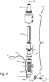
FIG. 3 is a perspective view of an embodiment of a deep rolling tool. -
FIG. 4 is an exploded view of the deep rolling tool embodiment inFIG. 3 . -
FIG. 5 shows an embodiment of a deep rolling tool attached to a robot arm for accessing difficult to process areas of a workpiece with the deep rolling tool. - Generally, a roller disk with a crowned or otherwise nonplanar working surface about its perimeter can be attached to an end of a spring loaded shaft. The tool can be attached to a device to process one or more parts. The tool uses multiple tool passes to induce residual compressive stresses while maintaining the appropriate level or range of contact stresses at the roller's point of contact via selective spring loading of the tool.
-
FIG. 1 showsworkpiece 10, which can be supported in a suitable fixture (not shown). Workpiece 10 has airfoil 12 anddovetail root 14. At least one nonplanar surface is to be processed (e.g.,junction 16 betweenairfoil 12 and root 14) to have residual compressive stresses near the surface in and aroundjunction 16. - In this example,
workpiece 10 is an aluminum alloy fan blade for a turbofan engine, but the process can be adapted to nearly any workpiece having a nonplanar surface into which residual compression stresses are desired to be incorporated. - Thus in the example of a dovetail-rooted blade, it is desired to increase residual compressive stresses around both sides of
junction 16 betweendovetail root 14 andairfoil 12. As most of the bending stresses are concentrated aroundjunction 16, this location is most prone to fatigue damage. The combined effects of fatigue and corrosion pitting can be reduced via deep rolling because the residual compressive stress induced by application of the rolling tool (shown in subsequent figures) reduces the pathways for damage to propagate through the part, extending the time before failure or replacement. -
FIG. 2 showsroller disk 20processing junction 16 of workpiece /blade 10 betweenairfoil 12 androot 14.Disk 20 can be joined to a portion ofhub 22 withroller disk 20 rotatable about anaxis 24 angled relative to a downward force direction F. Here,axis 24 is normal to downward force direction F and thus, resulting downward contact force is applied tojunction 16 generally in direction F as well. -
Disk 20 has workingsurface 26 about itsperimeter 28, and can include a profile along its width 30 (best seen inFIGS. 3 and4 ), such that an effective radius of the roller disk varies along a width thereof. It can be seen inFIG. 2 that the disk should be of a radius that provides clearance over protruding regions of the workpiece (e.g., dovetail root 14). In a conventional arrangement for processing a modern aluminum fan blade dovetail, this requires a minimum disk radius of about 2 inches (51 cm), but the size will vary depending on a particular application. - Hub 22 connects
disk 20 to a shaft through which the downward force can be applied in direction F. One example embodiment of a deep rolling tool incorporating this construction is shown inFIG. 3 .Tool assembly 31 includes spring-loadedshaft assembly 32 disposed alongaxis 34, which is parallel to downward forcedirection F. Hub 22 can have a first /upper portion 36A alongaxis 34 and a second /lower portion 36B at a nonzero angle relative toaxis 34. This angle is therefore consistent with the nonzero angle betweenaxis 24 and direction F. - Operation of
tool assembly 31 can be as follows. The rolling operation can include applying a force in direction F alongaxis 34 such that the applied force is transferred through spring-loadedshaft assembly 32,hub 22, androller disk 20 to a first nonplanar surface of the workpiece (e.g., junction 16). The resulting force applied to the first nonplanar surface varies along the width of workingsurface 26 of the disk due to the variable profile across width 30 (seen inFIG. 2 ). - At least one rolling operation can be performed on a nonplanar surface using a tool like that shown in
FIG. 3. FIG. 3 depictsroller disk 20 joined to second /lower portion 36B ofhub 22, and which is rotatable aboutaxis 24 through second /lower portion 36B ofhub 22.Roller disk 20 can be supported on one or more bearings (best seen in the exploded view ofFIG. 4 ). As noted with respect toFIG. 2 ,disk 20 can have workingsurface 26 aboutperimeter 28, and can include a variable or crowned profile. As a result, an effective radius (and thus applied bearing stresses) ofroller disk 20 varies along workingsurface 26. Though shown as a crowned roller with a single center peak, workingsurface 26 can additionally have one or more peaks, troughs, etc. The resulting profile can thus either be curved, slanted, or flat. - Spring-loaded
shaft assembly 32 can take several different forms. In one non-limiting example,resilient element 46 is disposed atdistal end 48 ofshaft assembly 32, while a rigid shaft 50 (best seen inFIG. 4 ) can be supported on a device to restrain its movement only alongfirst axis 14. This can include one or morelinear bearings 49. In other embodiments,shaft assembly 32 can include a flexible beam without a separate resilient element. - With regard to
resilient element 46, certain non-limiting embodiments include a plurality ofstacked Belleville washers 52 which can be selected in number and properties in order to provide a desired level of resilience. Alternatively,resilient element 30 can include a diaphragm spring or the like. - Certain embodiments of
tool assembly 31 can also optionally include other elements. For one,tool assembly 31 can includetool holder 56 mounted to proximal end 58 ofrigid shaft 50 and/orshaft assembly 32.Tool holder 56 can be a standard or custom adapter or other device to facilitate attachment oftool assembly 31 to commercially available multi-axis computerized numerical control (CNC) machines (not shown).Tool holder 56 can additionally or alternatively facilitate attachment to other devices capable of steeringtool assembly 31 while simultaneously applying sufficient (but not excessive) force in downward direction F to induce the desired compressive stresses. - In certain embodiments,
tool assembly 31 can includeload cell 60 to measure the force at the contact surface (seeFIG. 4 ).Load cell 60 can optionally be disposed alongaxis 34 adjacent toresilient element 46, and can include a wired and/orwireless connection 62 forcontroller 64. This will be explained in more detail below. -
FIG. 4 shows an exploded view oftool assembly 31 fromFIG. 3 . In addition to the elements described generally above,tool assembly 31 can include the following details. As noted,shaft assembly 32 is restricted to movement only alongfirst axis 14. Thus, in this example embodiment,shaft assembly 32 can includelinear bearing 48 arranged alongaxis 34 for supportingrigid shaft 50. This simplifies determination of the downward force that needs to be applied in direction F, as any deflection away from that axis causes a reduction in the actual downward force vectors, while also applying unwanted transverse forces on the tool working surface. - In the example shown,
hub 22 includes first and second portions 50A, 50B which form a right, or other, angle therebetween.Roller disk 20 is supported on a bearing or other device so that it is rotatable aboutaxis 24. Here, with the right angle,axis 24 is perpendicular tofirst axis 14. In this example, workingsurface 26 ofroller disk 20 is symmetrically crowned from a center to opposing first and second edges. Alternatively, working surface varies according to a desired load profile along the tool path and can include peaks, troughs, curves, etc. -
Shaft assembly 32 can be calibrated before or between uses to provide a desired force concentration at workingsurface 26 ofroller disk 20. In the example shown, at least one ofrigid shaft 50 and resilient element 36 can be calibrated so that the force applied to the tool in direction F (shown inFIGS. 2 and3 ) and transmitted throughroller disk 20 is sufficient to impart a residual compression stress in the workpiece at the first nonplanar surface (e.g.junction 16 inFIGS. 1 and2 ). - The deep rolling tool described heretofore can be used in a number of different applications, depending on the required accuracy and precision of the applied forces needed. Success in some cases can be achieved by merely controlling the tool load within previously determined upper and lower bounds, such as through spring loading the tool and applying a target amount of compression to the spring. The compliance obtained by using a spring loaded tool enables an acceptable level of load control during processing but there is no record of what the actual contact stress was over the surface. However, this is the cheapest and often simplest option, where any suitable mechanical device with an ability to provide a controlled downward force can be used.
- Some parts, however, require that the actual residual stresses at the working surface be verified. There are currently no non-destructive evaluation techniques that can be used to verify the correct level of residual stress was achieved during processing. Thus, a load cell or another feedback mechanism can be incorporated into the tool that allows monitoring and/or real-time adjustment of the force applied through the roller to the workpiece. The tool can process a part using multiple tool passes while maintaining the appropriate level of contact stress at the roller's point of contact. In some cases, the feedback is logged for quality control, so that it can be determined whether any irregularities occurred in the process. This is useful where scrapping and reprocessing parts is not a significant cost or limiting factor.
- As was shown and described above,
load cell 60 can optionally be incorporated intotool assembly 32.Load cell 60, in certain embodiments, is contiguous to resilient element 46 (e.g., plurality of Belleville washers 52), and enables real time monitoring of the applied load during processing. A deep rolling tool with an integral load cell thus enables verification of a key process parameter, roller load, which is critical for quality control in many production environments. - Process consistency could be further enhanced by using the load cell for closed loop load control which improve the precision with which the load could be maintained. Such a system would be much more tolerant of dimensional variability in the components being processed. It will also ensure that there are no microcracks on surface due to inadvertent localized application of intensive pressure.
-
Load cell 60 can be in wired or wireless communication with acontroller 64 and/or monitor adapted to receive wired or wireless signals corresponding to an instantaneous load on resilient element 36. Controller /monitor 64 can include closed-loop feedback logic, by which it can be adapted to vary a force applied in direction F (see alsoFIGS. 2 and3 ) ontool assembly 31, alongaxis 34. Operatingload cell 60 can generate signals corresponding to an instantaneous load onresilient element 46. The magnitude of the force can be based at least in part on one or more of the signals received from and generated byload cell 60. The applied force is varied based on a plurality of signals fromload cell 60 to impart a substantially equal residual compression stress in the workpiece along a tool rolling path on the first nonplanar surface. - The nature of many tools for CNC machines requires that they be axisymmetric (generally to facilitate rotation of the tool working end). Thus CNC programming and many common subroutines are generally tailored to this expectation. In contrast, the non-axisymmetric nature of
tool assembly 31 can require that the CNC machine be provided with more complex programming even for some relatively simple tool paths. Depending on the desired tool paths and number of passes, programming and use of a CNC machine may be unnecessary or prohibitively complex, in which case,tool assembly 31 can be mounted to a different machine to apply the desired force over the contact path. While certain processes can generally performed using a specialized tool in a conventional CNC milling machine, the deep rolling tool can be inconsistent with generic subroutines and tool paths used to manipulate conventional axisymmetric tools. Therefore use of the deep rolling tool, which is not axisymmetric, has additional path programming constraints. While planar surfaces can be processed by the deep rolling tool using a 3-axis CNC machine, more complex geometry components will require at least a 5-axis machine and in some instances a 6-axis machine may be necessary. Maintaining the normality and orientation constraints for deep rolling of complex component geometries can be challenging as the tool path programming software won't automatically satisfy these required constraints. While creative programming can generally overcome these issues it may require an experienced and highly skilled programmer. - To overcome this, deep
rolling tool assembly 31 can be attached to the end of arobotic arm 100 as shown inFIG. 5 .Robotic assembly 100 can include, for example, a plurality oflinear arms 102 connected in series betweenbase end 104 and workingend 106. Adjacent ones ofarms 102 can be connected via a corresponding plurality ofmulti-axis joints 110 such that workingend 106 is articulated by movement of one or more ofarms 102 relative to one or more ofmulti-axis joints 110. - Operation of a robotic assembly such as
assembly 100 inFIG. 5 can include using it to apply a downward force over a rolling path of non-axisymmetric deeprolling tool assembly 31. The downward force is applied to a proximal end of a spring-loaded tool shaft (best seen inFIG. 2 ) aligned with a first axis, such that the downward force is transferred through the shaft to a hub disposed at a distal end of the shaft assembly (also best seen inFIG. 2 ). In certain embodiments,robotic assembly 100 is sufficiently programmed and/or controlled to provide the appropriate instantaneous feedback of downward force, and the resilient element intool 31 can be modified or omitted as needed. - As described above, the transferred downward force is transmitted from an upper portion of the hub aligned with the first axis to a lower portion of the hub parallel to a second axis. The second axis forms a nonzero angle relative to the first axis, about which a roller disk is supported by one or more bearings. A resulting compressive force is applied to the first nonplanar surface of the workpiece via a working surface of the roller disk.
- A typical commercial robot arm has more degrees of freedom than a 5-axis milling machine which facilitates processing of complex geometry parts. Current commercially available robot arms have been developed to the point where they can withstand the combination of high loads and precision required in deep rolling applications. The software for controlling robot arms is different to that for CNC milling machines and is more suited to maintaining the required orientation constraints of a multi-axis deep rolling tool. Also, it is easier to accommodate processing of large components using a robot arm, as the part does not have to fit inside the machine as it does with a milling machine.
- An embodiment of a tool assembly according to an exemplary embodiment of this disclosure, among other possible things, includes spring-loaded shaft assembly disposed along a first axis; a hub connected to a distal end of the spring-loaded shaft assembly, the hub having an upper hub portion adjacent to the distal end of the spring-loaded shaft assembly aligned with the first axis, and a lower hub portion extending along a second axis, the second axis forming a nonzero angle relative to the first axis; and a roller disk joined to the lower portion of the hub, the roller disk having a working surface about its perimeter and being rotatable about the second axis parallel to the second portion of the hub. The working surface including a profile along its width such that an effective radius of the roller disk varies along a width thereof.
- The assembly of the preceding paragraph can optionally include, additionally and/or alternatively, any one or more of the following features, configurations and/or additional components:
A further embodiment of the foregoing assembly, wherein the shaft assembly comprises a flexible shaft. - A further embodiment of any of the foregoing assemblies, wherein the shaft assembly comprises: a rigid shaft; and a resilient element disposed at a distal end of the shaft assembly proximate to the hub.
- A further embodiment of any of the foregoing assemblies, wherein the rigid shaft comprises a linear bearing arranged along the first axis.
- A further embodiment of any of the foregoing assemblies, wherein the resilient element comprises a plurality of stacked Belleville washers.
- A further embodiment of any of the foregoing assemblies, wherein the resilient element comprises a diaphragm spring.
- A further embodiment of any of the foregoing assemblies, and further comprising a tool holder mounted to a proximal end of the shaft.
- A further embodiment of any of the foregoing assemblies, wherein the upper hub portion and the lower hub portion define a right angle such that the roller disk is rotatable about the second axis perpendicular to the first axis.
- A further embodiment of any of the foregoing assemblies, wherein the working surface of the roller disk includes a profile along its width such that an effective radius of the roller disk varies along a width thereof.
- A further embodiment of any of the foregoing assemblies, wherein the working surface profile of the roller disk is crowned from a center to opposing first and second edges.
- An embodiment of a method according to an exemplary embodiment of this disclosure, among other possible things, includes supporting a workpiece in a fixture, the workpiece having a first nonplanar surface: and performing a first rolling operation on the first nonplanar surface using a non-axisymmetric tool assembly, the first rolling operation comprising: applying a downward force to a proximal end of a spring-loaded deep rolling tool shaft aligned with a first axis, the downward force applied along the first axis such that the downward force is transferred through the shaft to a hub disposed at a distal end of the shaft assembly; and transmitting the transferred downward force from an upper portion of the hub aligned with the first axis to a lower portion of the hub parallel to a second axis, the second axis forming a nonzero angle relative to the first axis, about which a roller disk is supported by one or more bearings, such that a resulting compressive force is applied to the first nonplanar surface of the workpiece via a working surface of the roller disk. The working surface includes a profile along its width such that an effective radius of the roller disk varies along a width thereof, such that the resulting compressive force applied to the first nonplanar surface varies along the width of the working surface.
- The method of the preceding paragraph can optionally include, additionally and/or alternatively, any one or more of the following features, configurations, steps, and/or additional components:
A further embodiment of any of the foregoing methods, wherein the working surface of the roller disk is crowned from a center to opposing first and second edges. - A further embodiment of any of the foregoing methods, wherein the deep rolling tool shaft comprises: a rigid shaft extending along the first axis; and a resilient element disposed at a distal end of the rigid shaft adjacent to the hub.
- A further embodiment of any of the foregoing methods, wherein the resilient element comprises a plurality of stacked Belleville washers.
- A further embodiment of any of the foregoing methods, wherein the rigid shaft is supported by a linear bearing to restrain movement of the rigid shaft to the first axis.
- A further embodiment of any of the foregoing methods, and further comprising connecting the proximal end of the shaft to an automated machine.
- A further embodiment of any of the foregoing methods, and further comprising using the tool to perform a second rolling operation on a second nonplanar surface of the workpiece.
- A further embodiment of any of the foregoing methods, wherein the second nonplanar surface is directly opposite the first nonplanar surface.
- A further embodiment of any of the foregoing methods, wherein the roller disk is rotatable about the second axis perpendicular to the first axis.
- While the invention has been described with reference to an exemplary embodiment(s), it will be understood by those skilled in the art that various changes may be made and equivalents may be substituted for elements thereof without departing from the scope of the invention. In addition, many modifications may be made to adapt a particular situation or material to the teachings of the invention without departing from the essential scope thereof. Therefore, it is intended that the invention not be limited to the particular embodiment(s) disclosed, but that the invention will include all embodiments falling within the scope of the appended claims.
Claims (14)
- A non axisymmetric tool assembly (31) comprising:a spring-loaded shaft assembly (32) disposed along a first axis (34);a hub (22) connected to a distal end of the spring-loaded shaft assembly (32), the hub (22) having an upper hub portion (36A) adjacent to the distal end of the spring-loaded shaft assembly (32) aligned with the first axis (34), and a lower hub portion (36B) extending along a second axis (24), the second axis (24) forming a non zero angle relative to the first axis (34);a roller disk (20) joined to the lower portion (36B) of the hub, the roller disk (20) having a working surface (26) about its perimeter and being rotatable about the second axis (24) parallel to the second portion (36B) of the hub, the working surface (26) including a profile along its width (30) such that an effective radius of the roller disk (20) varies along a width thereof.
- The assembly (31) of claim 1, wherein the shaft assembly (32) comprises a flexible shaft.
- The assembly (31) of claim 1, wherein the shaft assembly (32) comprises:a rigid shaft (50); anda resilient element (46) disposed at a distal end (48) of the shaft assembly (32) proximate to the hub.
- The assembly (31) of claim 3 wherein the rigid shaft (50) is supported by a linear bearing (49) arranged along the first axis (34).
- The assembly (31) of claim 3 or 4, wherein the resilient element (46) comprises a plurality of stacked Belleville washers (52), or
wherein the resilient element comprises a diaphragm spring. - The assembly (31) of any preceding claim, and further comprising a tool holder (56) mounted to a proximal end (58) of the shaft.
- The assembly (31) of any preceding claim, wherein the upper hub portion (36A) and the lower hub portion (36B) define a right angle,
wherein, optionally, the roller disk (20) is rotatable about the second axis (24) perpendicular to the first axis. - The assembly (31) of any preceding claim, wherein the working surface (26) of the roller disk (20) is crowned from a center to opposing first and second edges.
- A method comprising:supporting a workpiece (10) in a fixture, the workpiece (10) having a first nonplanar surface: andperforming a first rolling operation on the first nonplanar surface using a non axisymmetric tool assembly (31), the first rolling operation comprising:transmitting the transferred downward force from an upper portion of the hub (36A) aligned with the first axis (34) to a lower portion of the hub (36B) parallel to a second axis (24), the second axis (24) forming a non-zero angle relative to the first axis (34), about which a roller disk (20) is supported by one or more bearings, such that a resulting compressive force is applied to the first nonplanar surface of the workpiece (10) via a working surface (26) of the roller disk; wherein the working surface (26) includes a profile along its width (30) such that an effective radius of the roller disk (20) varies along a width thereof, such that the resulting compressive force applied to the first nonplanar surface varies along the width (30) of the working surface,
applying a downward force to a proximal end of a spring-loaded deep rolling tool shaft (32) aligned with a first axis (34), the downward force applied along the first axis (34) such that the downward force is transferred through the shaft (32) to a hub disposed at a distal end of the shaft assembly; - The method of claim 9, wherein the working surface (26) of the roller disk (20) is crowned from a center to opposing first and second edges.
- The method of claim 9 or 10, wherein the deep rolling tool shaft (32) comprises a flexible shaft, or
wherein the deep rolling tool shaft (32) comprises:a rigid shaft (50) extending along the first axis (34); anda resilient element (46) disposed at a distal end (48) of the rigid shaft (50) adjacent to the hub. - The method of claim 11, wherein the resilient element (46) comprises a plurality of stacked Belleville washers (52), or
wherein the resilient element (46) comprises a diaphragm spring, and / or
wherein, optionally, the rigid shaft (50) is supported by a linear bearing to restrain movement of the rigid shaft to the first axis. - The method of any of claims 9 to 12 and further comprising using the tool to perform a second rolling operation on a second nonplanar surface of the workpiece (10),
wherein, optionally, the second nonplanar surface is directly opposite the first nonplanar surface. - The method of any of claims 9 to 13, wherein the roller disk (20) is rotatable about the second axis (24) perpendicular to the first axis (34).
Applications Claiming Priority (1)
| Application Number | Priority Date | Filing Date | Title |
|---|---|---|---|
| US15/385,648 US10786883B2 (en) | 2016-12-20 | 2016-12-20 | Deep rolling tool and method |
Publications (2)
| Publication Number | Publication Date |
|---|---|
| EP3338949A1 EP3338949A1 (en) | 2018-06-27 |
| EP3338949B1 true EP3338949B1 (en) | 2020-04-01 |
Family
ID=60543397
Family Applications (1)
| Application Number | Title | Priority Date | Filing Date |
|---|---|---|---|
| EP17204596.5A Active EP3338949B1 (en) | 2016-12-20 | 2017-11-30 | Deep rolling tool and method |
Country Status (2)
| Country | Link |
|---|---|
| US (1) | US10786883B2 (en) |
| EP (1) | EP3338949B1 (en) |
Families Citing this family (4)
| Publication number | Priority date | Publication date | Assignee | Title |
|---|---|---|---|---|
| CN110091121A (en) * | 2019-05-30 | 2019-08-06 | 西南交通大学 | A method of axle surface is handled using rolling techniques |
| JP7318135B2 (en) * | 2020-07-06 | 2023-07-31 | エックスワイゼット ロボティクス グローバル インコーポレイテッド | Structural load cell case for containing sensors in robotic systems |
| CN113059314B (en) * | 2021-03-23 | 2022-04-15 | 北京理工大学 | Variable angle low temperature lubrication special inner cooling rolling tool |
| CN113547866B (en) * | 2021-08-10 | 2022-05-17 | 常州市武进海力制辊有限公司 | High-precision anilox roller mechanical embossing machine |
Family Cites Families (27)
| Publication number | Priority date | Publication date | Assignee | Title |
|---|---|---|---|---|
| US3395441A (en) * | 1965-10-23 | 1968-08-06 | Trw Inc | Method of spin swedging inserts in housings |
| US5099558A (en) * | 1988-04-25 | 1992-03-31 | The B. F. Goodrich Company | Burnishing tool holder |
| EP0577876B1 (en) | 1992-07-09 | 1996-09-04 | TRIENGINEERING Co., Ltd. | Roller type hemming apparatus |
| DE4309176C2 (en) * | 1993-03-22 | 1995-10-19 | Siemens Ag | Process for deep rolling a component |
| US6415486B1 (en) | 2000-03-01 | 2002-07-09 | Surface Technology Holdings, Ltd. | Method and apparatus for providing a residual stress distribution in the surface of a part |
| JP4918960B2 (en) * | 2003-11-19 | 2012-04-18 | 日産自動車株式会社 | Micro roll forming device for substantially cylindrical member |
| US7188398B2 (en) | 2004-01-17 | 2007-03-13 | Surface Technology Holdings, Ltd. | Method for improving the magnitude of compressive stress developed in the surface of a part |
| US7152447B2 (en) | 2004-03-30 | 2006-12-26 | Tesco Engineering, Inc. | Roller type hemming apparatus |
| JP5113422B2 (en) * | 2007-05-23 | 2013-01-09 | 富士精工株式会社 | Roller burnishing device with pressure detection device |
| US20090235505A1 (en) * | 2008-03-24 | 2009-09-24 | Hirotec America, Inc. | Hem flange control roller |
| US8601659B2 (en) * | 2011-02-10 | 2013-12-10 | Surface Technology Holdings, Ltd. | Burnishing tool and method for burnishing |
| US9352376B2 (en) * | 2011-05-24 | 2016-05-31 | Comau S.P.A. | Hemming head device and method |
| US11000899B2 (en) | 2012-01-29 | 2021-05-11 | Raytheon Technologies Corporation | Hollow airfoil construction utilizing functionally graded materials |
| US9789582B2 (en) | 2012-07-05 | 2017-10-17 | Surface Technology Holdings Ltd. | Method and compression apparatus for introducing residual compression into a component having a regular or an irregular shaped surface |
| PT2821159T (en) | 2013-07-01 | 2016-11-16 | Comau Spa | Tool head for performing industrial operations having a wireless monitoring system |
| US20150033816A1 (en) | 2013-07-31 | 2015-02-05 | Ford Global Technologies, Llc | Double Ended Hemming Roller |
| JP5971226B2 (en) | 2013-11-01 | 2016-08-17 | 株式会社安川電機 | Robot system and method of manufacturing workpiece |
| EP2920868B1 (en) | 2013-11-08 | 2021-08-25 | Ingersoll-Rand Industrial U.S., Inc. | Casting technology for induction rotor assemblies |
| US9573175B2 (en) | 2013-12-18 | 2017-02-21 | United Technologies Corporation | Deep rolling tool for blade fatigue life enhancement |
| US9421602B2 (en) | 2013-12-18 | 2016-08-23 | United Technologies Corporation | Machine for deep rolling tool positioning |
| US9573184B2 (en) | 2013-12-18 | 2017-02-21 | United Technologies Corporation | Deep rolling tool for processing blade root |
| WO2015105655A1 (en) | 2014-01-07 | 2015-07-16 | United Technologies Corporation | Systems and methods for determining a tool path for automated flexible fork peening |
| EP3107668A1 (en) | 2014-02-19 | 2016-12-28 | Comau S.p.A. | Roller hemming head having a replaceable roller-carrying unit |
| ES2553618B1 (en) * | 2014-05-08 | 2016-09-21 | Ingemat, S.L. | TOOL FOR ENGRAPADO BY ROLDANA |
| JP6548462B2 (en) | 2014-06-17 | 2019-07-24 | ユナイテッド テクノロジーズ コーポレイションUnited Technologies Corporation | Additional manufacturing method |
| DE202014007648U1 (en) * | 2014-09-18 | 2015-12-22 | Hegenscheidt Mfd Gmbh | Rolling unit for deep rolling the wheel treads of rail vehicles |
| CN205464920U (en) | 2015-05-27 | 2016-08-17 | 美建建筑系统(中国)有限公司 | Gutter funnel nozzle stub welding set |
-
2016
- 2016-12-20 US US15/385,648 patent/US10786883B2/en active Active
-
2017
- 2017-11-30 EP EP17204596.5A patent/EP3338949B1/en active Active
Non-Patent Citations (1)
| Title |
|---|
| None * |
Also Published As
| Publication number | Publication date |
|---|---|
| US10786883B2 (en) | 2020-09-29 |
| US20180169828A1 (en) | 2018-06-21 |
| EP3338949A1 (en) | 2018-06-27 |
Similar Documents
| Publication | Publication Date | Title |
|---|---|---|
| EP3338949B1 (en) | Deep rolling tool and method | |
| JP6630073B2 (en) | Machining device and machining method | |
| EP2018235B1 (en) | Surface treatment apparatus and method | |
| US9636827B2 (en) | Robot system for performing force control | |
| EP3338939B1 (en) | Deep rolling tool and method | |
| JP3318618B2 (en) | Method and programmable positioner for assembling an assembly without deformation stress | |
| US20140007394A1 (en) | Method and compression apparatus for introducing residual compression into a component having a regular or an irregular shaped surface | |
| EP2740568B1 (en) | Automated polishing systems and methods | |
| EP2617517B1 (en) | Roll Peening Tooling and Process | |
| CA2938232A1 (en) | Machine toolpath compensation using vibration sensing | |
| US8511130B2 (en) | Method for preventing or arresting crack development and propagation | |
| EP3338950A1 (en) | Deep rolling tool and method | |
| JP6924563B2 (en) | Positioning control device control method and positioning control device | |
| CN109789521B (en) | Automated hammering method and automation system for carrying out said method | |
| JP6264702B2 (en) | Processing equipment | |
| US10245630B2 (en) | Smart fixture distortion correction system | |
| US20240060165A1 (en) | Surface treatment system design for high fatigue life hollow fan blades | |
| JP2004050300A (en) | Method and apparatus for automatically finishing large-sized workpiece | |
| KR100237807B1 (en) | Press processing method and press processing device | |
| CN113319687A (en) | Controlling contact forces in a machine tool | |
| CA2845964C (en) | Method and compression apparatus for introducing residual compression into a component having a regular or an irregular shaped surface | |
| JP2022159211A (en) | Tool floating mechanism, machining device, and machining device tool floating mechanism | |
| JPH0332583A (en) | Industrial robot |
Legal Events
| Date | Code | Title | Description |
|---|---|---|---|
| PUAI | Public reference made under article 153(3) epc to a published international application that has entered the european phase |
Free format text: ORIGINAL CODE: 0009012 |
|
| STAA | Information on the status of an ep patent application or granted ep patent |
Free format text: STATUS: THE APPLICATION HAS BEEN PUBLISHED |
|
| AK | Designated contracting states |
Kind code of ref document: A1 Designated state(s): AL AT BE BG CH CY CZ DE DK EE ES FI FR GB GR HR HU IE IS IT LI LT LU LV MC MK MT NL NO PL PT RO RS SE SI SK SM TR |
|
| AX | Request for extension of the european patent |
Extension state: BA ME |
|
| STAA | Information on the status of an ep patent application or granted ep patent |
Free format text: STATUS: REQUEST FOR EXAMINATION WAS MADE |
|
| 17P | Request for examination filed |
Effective date: 20181221 |
|
| RBV | Designated contracting states (corrected) |
Designated state(s): AL AT BE BG CH CY CZ DE DK EE ES FI FR GB GR HR HU IE IS IT LI LT LU LV MC MK MT NL NO PL PT RO RS SE SI SK SM TR |
|
| GRAP | Despatch of communication of intention to grant a patent |
Free format text: ORIGINAL CODE: EPIDOSNIGR1 |
|
| STAA | Information on the status of an ep patent application or granted ep patent |
Free format text: STATUS: GRANT OF PATENT IS INTENDED |
|
| INTG | Intention to grant announced |
Effective date: 20190429 |
|
| GRAJ | Information related to disapproval of communication of intention to grant by the applicant or resumption of examination proceedings by the epo deleted |
Free format text: ORIGINAL CODE: EPIDOSDIGR1 |
|
| STAA | Information on the status of an ep patent application or granted ep patent |
Free format text: STATUS: REQUEST FOR EXAMINATION WAS MADE |
|
| GRAP | Despatch of communication of intention to grant a patent |
Free format text: ORIGINAL CODE: EPIDOSNIGR1 |
|
| STAA | Information on the status of an ep patent application or granted ep patent |
Free format text: STATUS: GRANT OF PATENT IS INTENDED |
|
| INTC | Intention to grant announced (deleted) | ||
| INTG | Intention to grant announced |
Effective date: 20191014 |
|
| GRAS | Grant fee paid |
Free format text: ORIGINAL CODE: EPIDOSNIGR3 |
|
| GRAA | (expected) grant |
Free format text: ORIGINAL CODE: 0009210 |
|
| STAA | Information on the status of an ep patent application or granted ep patent |
Free format text: STATUS: THE PATENT HAS BEEN GRANTED |
|
| AK | Designated contracting states |
Kind code of ref document: B1 Designated state(s): AL AT BE BG CH CY CZ DE DK EE ES FI FR GB GR HR HU IE IS IT LI LT LU LV MC MK MT NL NO PL PT RO RS SE SI SK SM TR |
|
| REG | Reference to a national code |
Ref country code: GB Ref legal event code: FG4D |
|
| REG | Reference to a national code |
Ref country code: CH Ref legal event code: EP Ref country code: AT Ref legal event code: REF Ref document number: 1250763 Country of ref document: AT Kind code of ref document: T Effective date: 20200415 |
|
| REG | Reference to a national code |
Ref country code: DE Ref legal event code: R096 Ref document number: 602017013924 Country of ref document: DE |
|
| REG | Reference to a national code |
Ref country code: IE Ref legal event code: FG4D |
|
| PG25 | Lapsed in a contracting state [announced via postgrant information from national office to epo] |
Ref country code: BG Free format text: LAPSE BECAUSE OF FAILURE TO SUBMIT A TRANSLATION OF THE DESCRIPTION OR TO PAY THE FEE WITHIN THE PRESCRIBED TIME-LIMIT Effective date: 20200701 |
|
| REG | Reference to a national code |
Ref country code: NL Ref legal event code: MP Effective date: 20200401 |
|
| REG | Reference to a national code |
Ref country code: LT Ref legal event code: MG4D |
|
| PG25 | Lapsed in a contracting state [announced via postgrant information from national office to epo] |
Ref country code: IS Free format text: LAPSE BECAUSE OF FAILURE TO SUBMIT A TRANSLATION OF THE DESCRIPTION OR TO PAY THE FEE WITHIN THE PRESCRIBED TIME-LIMIT Effective date: 20200801 Ref country code: FI Free format text: LAPSE BECAUSE OF FAILURE TO SUBMIT A TRANSLATION OF THE DESCRIPTION OR TO PAY THE FEE WITHIN THE PRESCRIBED TIME-LIMIT Effective date: 20200401 Ref country code: CZ Free format text: LAPSE BECAUSE OF FAILURE TO SUBMIT A TRANSLATION OF THE DESCRIPTION OR TO PAY THE FEE WITHIN THE PRESCRIBED TIME-LIMIT Effective date: 20200401 Ref country code: NO Free format text: LAPSE BECAUSE OF FAILURE TO SUBMIT A TRANSLATION OF THE DESCRIPTION OR TO PAY THE FEE WITHIN THE PRESCRIBED TIME-LIMIT Effective date: 20200701 Ref country code: GR Free format text: LAPSE BECAUSE OF FAILURE TO SUBMIT A TRANSLATION OF THE DESCRIPTION OR TO PAY THE FEE WITHIN THE PRESCRIBED TIME-LIMIT Effective date: 20200702 Ref country code: SE Free format text: LAPSE BECAUSE OF FAILURE TO SUBMIT A TRANSLATION OF THE DESCRIPTION OR TO PAY THE FEE WITHIN THE PRESCRIBED TIME-LIMIT Effective date: 20200401 Ref country code: NL Free format text: LAPSE BECAUSE OF FAILURE TO SUBMIT A TRANSLATION OF THE DESCRIPTION OR TO PAY THE FEE WITHIN THE PRESCRIBED TIME-LIMIT Effective date: 20200401 Ref country code: LT Free format text: LAPSE BECAUSE OF FAILURE TO SUBMIT A TRANSLATION OF THE DESCRIPTION OR TO PAY THE FEE WITHIN THE PRESCRIBED TIME-LIMIT Effective date: 20200401 Ref country code: PT Free format text: LAPSE BECAUSE OF FAILURE TO SUBMIT A TRANSLATION OF THE DESCRIPTION OR TO PAY THE FEE WITHIN THE PRESCRIBED TIME-LIMIT Effective date: 20200817 |
|
| REG | Reference to a national code |
Ref country code: AT Ref legal event code: MK05 Ref document number: 1250763 Country of ref document: AT Kind code of ref document: T Effective date: 20200401 |
|
| PG25 | Lapsed in a contracting state [announced via postgrant information from national office to epo] |
Ref country code: HR Free format text: LAPSE BECAUSE OF FAILURE TO SUBMIT A TRANSLATION OF THE DESCRIPTION OR TO PAY THE FEE WITHIN THE PRESCRIBED TIME-LIMIT Effective date: 20200401 Ref country code: LV Free format text: LAPSE BECAUSE OF FAILURE TO SUBMIT A TRANSLATION OF THE DESCRIPTION OR TO PAY THE FEE WITHIN THE PRESCRIBED TIME-LIMIT Effective date: 20200401 Ref country code: RS Free format text: LAPSE BECAUSE OF FAILURE TO SUBMIT A TRANSLATION OF THE DESCRIPTION OR TO PAY THE FEE WITHIN THE PRESCRIBED TIME-LIMIT Effective date: 20200401 |
|
| PG25 | Lapsed in a contracting state [announced via postgrant information from national office to epo] |
Ref country code: AL Free format text: LAPSE BECAUSE OF FAILURE TO SUBMIT A TRANSLATION OF THE DESCRIPTION OR TO PAY THE FEE WITHIN THE PRESCRIBED TIME-LIMIT Effective date: 20200401 |
|
| REG | Reference to a national code |
Ref country code: DE Ref legal event code: R097 Ref document number: 602017013924 Country of ref document: DE |
|
| PG25 | Lapsed in a contracting state [announced via postgrant information from national office to epo] |
Ref country code: AT Free format text: LAPSE BECAUSE OF FAILURE TO SUBMIT A TRANSLATION OF THE DESCRIPTION OR TO PAY THE FEE WITHIN THE PRESCRIBED TIME-LIMIT Effective date: 20200401 Ref country code: ES Free format text: LAPSE BECAUSE OF FAILURE TO SUBMIT A TRANSLATION OF THE DESCRIPTION OR TO PAY THE FEE WITHIN THE PRESCRIBED TIME-LIMIT Effective date: 20200401 Ref country code: DK Free format text: LAPSE BECAUSE OF FAILURE TO SUBMIT A TRANSLATION OF THE DESCRIPTION OR TO PAY THE FEE WITHIN THE PRESCRIBED TIME-LIMIT Effective date: 20200401 Ref country code: RO Free format text: LAPSE BECAUSE OF FAILURE TO SUBMIT A TRANSLATION OF THE DESCRIPTION OR TO PAY THE FEE WITHIN THE PRESCRIBED TIME-LIMIT Effective date: 20200401 Ref country code: IT Free format text: LAPSE BECAUSE OF FAILURE TO SUBMIT A TRANSLATION OF THE DESCRIPTION OR TO PAY THE FEE WITHIN THE PRESCRIBED TIME-LIMIT Effective date: 20200401 Ref country code: SM Free format text: LAPSE BECAUSE OF FAILURE TO SUBMIT A TRANSLATION OF THE DESCRIPTION OR TO PAY THE FEE WITHIN THE PRESCRIBED TIME-LIMIT Effective date: 20200401 Ref country code: EE Free format text: LAPSE BECAUSE OF FAILURE TO SUBMIT A TRANSLATION OF THE DESCRIPTION OR TO PAY THE FEE WITHIN THE PRESCRIBED TIME-LIMIT Effective date: 20200401 |
|
| PLBE | No opposition filed within time limit |
Free format text: ORIGINAL CODE: 0009261 |
|
| STAA | Information on the status of an ep patent application or granted ep patent |
Free format text: STATUS: NO OPPOSITION FILED WITHIN TIME LIMIT |
|
| PG25 | Lapsed in a contracting state [announced via postgrant information from national office to epo] |
Ref country code: PL Free format text: LAPSE BECAUSE OF FAILURE TO SUBMIT A TRANSLATION OF THE DESCRIPTION OR TO PAY THE FEE WITHIN THE PRESCRIBED TIME-LIMIT Effective date: 20200401 Ref country code: SK Free format text: LAPSE BECAUSE OF FAILURE TO SUBMIT A TRANSLATION OF THE DESCRIPTION OR TO PAY THE FEE WITHIN THE PRESCRIBED TIME-LIMIT Effective date: 20200401 |
|
| 26N | No opposition filed |
Effective date: 20210112 |
|
| PG25 | Lapsed in a contracting state [announced via postgrant information from national office to epo] |
Ref country code: SI Free format text: LAPSE BECAUSE OF FAILURE TO SUBMIT A TRANSLATION OF THE DESCRIPTION OR TO PAY THE FEE WITHIN THE PRESCRIBED TIME-LIMIT Effective date: 20200401 |
|
| PG25 | Lapsed in a contracting state [announced via postgrant information from national office to epo] |
Ref country code: MC Free format text: LAPSE BECAUSE OF FAILURE TO SUBMIT A TRANSLATION OF THE DESCRIPTION OR TO PAY THE FEE WITHIN THE PRESCRIBED TIME-LIMIT Effective date: 20200401 |
|
| REG | Reference to a national code |
Ref country code: CH Ref legal event code: PL |
|
| PG25 | Lapsed in a contracting state [announced via postgrant information from national office to epo] |
Ref country code: LU Free format text: LAPSE BECAUSE OF NON-PAYMENT OF DUE FEES Effective date: 20201130 |
|
| REG | Reference to a national code |
Ref country code: BE Ref legal event code: MM Effective date: 20201130 |
|
| PG25 | Lapsed in a contracting state [announced via postgrant information from national office to epo] |
Ref country code: CH Free format text: LAPSE BECAUSE OF NON-PAYMENT OF DUE FEES Effective date: 20201130 Ref country code: LI Free format text: LAPSE BECAUSE OF NON-PAYMENT OF DUE FEES Effective date: 20201130 |
|
| REG | Reference to a national code |
Ref country code: IE Ref legal event code: MM4A |
|
| PG25 | Lapsed in a contracting state [announced via postgrant information from national office to epo] |
Ref country code: IE Free format text: LAPSE BECAUSE OF NON-PAYMENT OF DUE FEES Effective date: 20201130 |
|
| PG25 | Lapsed in a contracting state [announced via postgrant information from national office to epo] |
Ref country code: TR Free format text: LAPSE BECAUSE OF FAILURE TO SUBMIT A TRANSLATION OF THE DESCRIPTION OR TO PAY THE FEE WITHIN THE PRESCRIBED TIME-LIMIT Effective date: 20200401 Ref country code: MT Free format text: LAPSE BECAUSE OF FAILURE TO SUBMIT A TRANSLATION OF THE DESCRIPTION OR TO PAY THE FEE WITHIN THE PRESCRIBED TIME-LIMIT Effective date: 20200401 Ref country code: CY Free format text: LAPSE BECAUSE OF FAILURE TO SUBMIT A TRANSLATION OF THE DESCRIPTION OR TO PAY THE FEE WITHIN THE PRESCRIBED TIME-LIMIT Effective date: 20200401 |
|
| PG25 | Lapsed in a contracting state [announced via postgrant information from national office to epo] |
Ref country code: MK Free format text: LAPSE BECAUSE OF FAILURE TO SUBMIT A TRANSLATION OF THE DESCRIPTION OR TO PAY THE FEE WITHIN THE PRESCRIBED TIME-LIMIT Effective date: 20200401 |
|
| PG25 | Lapsed in a contracting state [announced via postgrant information from national office to epo] |
Ref country code: BE Free format text: LAPSE BECAUSE OF NON-PAYMENT OF DUE FEES Effective date: 20201130 |
|
| REG | Reference to a national code |
Ref country code: DE Ref legal event code: R081 Ref document number: 602017013924 Country of ref document: DE Owner name: RAYTHEON TECHNOLOGIES CORPORATION (N.D.GES.D.S, US Free format text: FORMER OWNER: UNITED TECHNOLOGIES CORPORATION, FARMINGTON, CONN., US |
|
| P01 | Opt-out of the competence of the unified patent court (upc) registered |
Effective date: 20230520 |
|
| PGFP | Annual fee paid to national office [announced via postgrant information from national office to epo] |
Ref country code: GB Payment date: 20231019 Year of fee payment: 7 |
|
| PGFP | Annual fee paid to national office [announced via postgrant information from national office to epo] |
Ref country code: FR Payment date: 20231019 Year of fee payment: 7 Ref country code: DE Payment date: 20231019 Year of fee payment: 7 |