EP3338830B1 - Syringe driving apparatus - Google Patents
Syringe driving apparatus Download PDFInfo
- Publication number
- EP3338830B1 EP3338830B1 EP17209918.6A EP17209918A EP3338830B1 EP 3338830 B1 EP3338830 B1 EP 3338830B1 EP 17209918 A EP17209918 A EP 17209918A EP 3338830 B1 EP3338830 B1 EP 3338830B1
- Authority
- EP
- European Patent Office
- Prior art keywords
- housing
- casing
- syringe
- driving member
- spiral spring
- Prior art date
- Legal status (The legal status is an assumption and is not a legal conclusion. Google has not performed a legal analysis and makes no representation as to the accuracy of the status listed.)
- Active
Links
- 238000005381 potential energy Methods 0.000 claims description 14
- 239000003814 drug Substances 0.000 claims description 10
- 230000002093 peripheral effect Effects 0.000 claims description 4
- 238000001802 infusion Methods 0.000 description 22
- 229940079593 drug Drugs 0.000 description 8
- 238000001990 intravenous administration Methods 0.000 description 8
- 238000006073 displacement reaction Methods 0.000 description 5
- 239000007788 liquid Substances 0.000 description 4
- 230000009471 action Effects 0.000 description 2
- 238000000418 atomic force spectrum Methods 0.000 description 1
- 238000004140 cleaning Methods 0.000 description 1
- 230000000295 complement effect Effects 0.000 description 1
- 230000001419 dependent effect Effects 0.000 description 1
- 230000005489 elastic deformation Effects 0.000 description 1
- 239000012530 fluid Substances 0.000 description 1
- 238000002347 injection Methods 0.000 description 1
- 239000007924 injection Substances 0.000 description 1
- 238000001746 injection moulding Methods 0.000 description 1
- 238000012423 maintenance Methods 0.000 description 1
- 238000002483 medication Methods 0.000 description 1
- 238000000034 method Methods 0.000 description 1
- 238000012986 modification Methods 0.000 description 1
- 230000004048 modification Effects 0.000 description 1
- 229940071643 prefilled syringe Drugs 0.000 description 1
- 230000008569 process Effects 0.000 description 1
- 230000008707 rearrangement Effects 0.000 description 1
- 238000006467 substitution reaction Methods 0.000 description 1
- 230000001225 therapeutic effect Effects 0.000 description 1
Images


Classifications
-
- A—HUMAN NECESSITIES
- A61—MEDICAL OR VETERINARY SCIENCE; HYGIENE
- A61M—DEVICES FOR INTRODUCING MEDIA INTO, OR ONTO, THE BODY; DEVICES FOR TRANSDUCING BODY MEDIA OR FOR TAKING MEDIA FROM THE BODY; DEVICES FOR PRODUCING OR ENDING SLEEP OR STUPOR
- A61M5/00—Devices for bringing media into the body in a subcutaneous, intra-vascular or intramuscular way; Accessories therefor, e.g. filling or cleaning devices, arm-rests
- A61M5/14—Infusion devices, e.g. infusing by gravity; Blood infusion; Accessories therefor
- A61M5/142—Pressure infusion, e.g. using pumps
- A61M5/145—Pressure infusion, e.g. using pumps using pressurised reservoirs, e.g. pressurised by means of pistons
- A61M5/1452—Pressure infusion, e.g. using pumps using pressurised reservoirs, e.g. pressurised by means of pistons pressurised by means of pistons
- A61M5/1454—Pressure infusion, e.g. using pumps using pressurised reservoirs, e.g. pressurised by means of pistons pressurised by means of pistons spring-actuated, e.g. by a clockwork
-
- A—HUMAN NECESSITIES
- A61—MEDICAL OR VETERINARY SCIENCE; HYGIENE
- A61M—DEVICES FOR INTRODUCING MEDIA INTO, OR ONTO, THE BODY; DEVICES FOR TRANSDUCING BODY MEDIA OR FOR TAKING MEDIA FROM THE BODY; DEVICES FOR PRODUCING OR ENDING SLEEP OR STUPOR
- A61M5/00—Devices for bringing media into the body in a subcutaneous, intra-vascular or intramuscular way; Accessories therefor, e.g. filling or cleaning devices, arm-rests
- A61M5/178—Syringes
- A61M5/31—Details
- A61M5/315—Pistons; Piston-rods; Guiding, blocking or restricting the movement of the rod or piston; Appliances on the rod for facilitating dosing ; Dosing mechanisms
- A61M5/31565—Administration mechanisms, i.e. constructional features, modes of administering a dose
- A61M5/31566—Means improving security or handling thereof
- A61M5/31571—Means preventing accidental administration
-
- A—HUMAN NECESSITIES
- A61—MEDICAL OR VETERINARY SCIENCE; HYGIENE
- A61M—DEVICES FOR INTRODUCING MEDIA INTO, OR ONTO, THE BODY; DEVICES FOR TRANSDUCING BODY MEDIA OR FOR TAKING MEDIA FROM THE BODY; DEVICES FOR PRODUCING OR ENDING SLEEP OR STUPOR
- A61M5/00—Devices for bringing media into the body in a subcutaneous, intra-vascular or intramuscular way; Accessories therefor, e.g. filling or cleaning devices, arm-rests
- A61M5/178—Syringes
- A61M5/20—Automatic syringes, e.g. with automatically actuated piston rod, with automatic needle injection, filling automatically
- A61M5/2033—Spring-loaded one-shot injectors with or without automatic needle insertion
-
- A—HUMAN NECESSITIES
- A61—MEDICAL OR VETERINARY SCIENCE; HYGIENE
- A61M—DEVICES FOR INTRODUCING MEDIA INTO, OR ONTO, THE BODY; DEVICES FOR TRANSDUCING BODY MEDIA OR FOR TAKING MEDIA FROM THE BODY; DEVICES FOR PRODUCING OR ENDING SLEEP OR STUPOR
- A61M5/00—Devices for bringing media into the body in a subcutaneous, intra-vascular or intramuscular way; Accessories therefor, e.g. filling or cleaning devices, arm-rests
- A61M5/178—Syringes
- A61M5/20—Automatic syringes, e.g. with automatically actuated piston rod, with automatic needle injection, filling automatically
- A61M2005/2026—Semi-automatic, e.g. user activated piston is assisted by additional source of energy
-
- A—HUMAN NECESSITIES
- A61—MEDICAL OR VETERINARY SCIENCE; HYGIENE
- A61M—DEVICES FOR INTRODUCING MEDIA INTO, OR ONTO, THE BODY; DEVICES FOR TRANSDUCING BODY MEDIA OR FOR TAKING MEDIA FROM THE BODY; DEVICES FOR PRODUCING OR ENDING SLEEP OR STUPOR
- A61M5/00—Devices for bringing media into the body in a subcutaneous, intra-vascular or intramuscular way; Accessories therefor, e.g. filling or cleaning devices, arm-rests
- A61M5/178—Syringes
- A61M5/20—Automatic syringes, e.g. with automatically actuated piston rod, with automatic needle injection, filling automatically
- A61M2005/2073—Automatic syringes, e.g. with automatically actuated piston rod, with automatic needle injection, filling automatically preventing premature release, e.g. by making use of a safety lock
-
- A—HUMAN NECESSITIES
- A61—MEDICAL OR VETERINARY SCIENCE; HYGIENE
- A61M—DEVICES FOR INTRODUCING MEDIA INTO, OR ONTO, THE BODY; DEVICES FOR TRANSDUCING BODY MEDIA OR FOR TAKING MEDIA FROM THE BODY; DEVICES FOR PRODUCING OR ENDING SLEEP OR STUPOR
- A61M2205/00—General characteristics of the apparatus
- A61M2205/02—General characteristics of the apparatus characterised by a particular materials
- A61M2205/0216—Materials providing elastic properties, e.g. for facilitating deformation and avoid breaking
-
- A—HUMAN NECESSITIES
- A61—MEDICAL OR VETERINARY SCIENCE; HYGIENE
- A61M—DEVICES FOR INTRODUCING MEDIA INTO, OR ONTO, THE BODY; DEVICES FOR TRANSDUCING BODY MEDIA OR FOR TAKING MEDIA FROM THE BODY; DEVICES FOR PRODUCING OR ENDING SLEEP OR STUPOR
- A61M39/00—Tubes, tube connectors, tube couplings, valves, access sites or the like, specially adapted for medical use
- A61M39/22—Valves or arrangement of valves
- A61M39/28—Clamping means for squeezing flexible tubes, e.g. roller clamps
Definitions
- the present invention relates to a syringe driving apparatus.
- it relates to a non-electrically powered syringe driving apparatus.
- Such syringes are disclosed for example in the patent publications (publication date: 14.2.2018), WO 2015/166286 A2 , EP 2 898 910 A1 and US 5 318 539 A .
- IV push intravenous infusion
- syringes to push medication through an intravenous infusion (IV) line, commonly called IV push
- IV push intravenous infusion
- some medications can only be absorbed intravenously.
- the syringe is connected to the peripheral Intravenous Tubing Port (Y Site).
- Y Site Intravenous Tubing Port
- the care giver has to consistently push the syringe from 2 mins to 10 mins to expel the contents.
- the care giver has to administer the dose appropriate to the medication.
- the disclosed embodiments allow the care giver or nurse to execute the injection of fluids into the IV line automatically, by providing a syringe driving apparatus that is pre-calibrated to push the plunger of a filled syringe within the intended duration appropriate for the medicinal contents, typically 2 mins to 10 mins.
- the syringe driving apparatus has a housing to which a syringe is attachable, a driving member movably coupled to the housing, and a resilient member connected to the housing and the driving member.
- the syringe driving apparatus may be configured as a single use, disposable device in order to obviate the need for proper cleaning and maintenance.
- the apparatus is also quick and easy to operate, allowing easy and efficient time and work management.
- the apparatus assists in ensuring compliance in administration duration with relevant standards.
- a pharmacy may prepare the prefilled syringe and dispense together with an appropriate syringe driving apparatus configured for the same infusion duration.
- Syringes and driving apparatus may be configured with respective codes, markings, labels etc., corresponding to different infusion duration, for easy identification and pairing.
- the nurse who uses the syringe for infusion together with the driving apparatus could check the pairing of syringe and contraption before connecting to patient, without having to actually push the syringe.
- the potential elastic energy of a deformed resilient member is used to push the plunger of a syringe attached to a syringe driving apparatus for automatic infusion.
- the syringe driving apparatus allows the pushing of the syringe plunger to be activated upon demand only after a filled syringe is attached.
- the syringe may be detached from the syringe driving apparatus by disengaging the flange of the syringe from the slots predisposed at the open end of the housing of the syringe driving apparatus.
- Embodiments of the present invention allow combinations of elastic properties, shapes, dimensions to cumulatively result the desired force profile to push a syringe plunger.
- a syringe driving apparatus has a housing, a driving member movably disposed in the housing, and a resilient member connecting the housing to the driving member.
- the driving member has a casing and a slider movably disposed in the casing.
- the resilient member is a spiral spring disposed in the casing, with an inner end connected to the slider and an outer end connected to the casing. Movement of the slider along an axial direction of the housing towards the back end causes the casing to rotate to wind the spiral spring to store potential energy in the spiral spring, and upon release of the potential energy, the spiral spring unwinds to move the casing towards the front end to press the plunger for infusion.
- a syringe driving apparatus 100 shown in Figs. 1 to 21 includes a housing 110, a driving member 140 coupled to the housing 110, and one or more resilient members, e.g. elastic band(s) 160 connecting the driving member 140 to the housing 110.
- Housing 110 has a front end 102 and a back end 106.
- the front end 102 has a retaining portion 124 configured to receive and fix a flange 84 of a syringe 80 thereto.
- Housing 110 may include an upper portion 110a and a lower portion 110b which is/are generally and interchangeably referred to as housing in the context of this disclosure.
- Driving member 140 has an actuator 142 disposed in the housing 110, a handle 146 disposed outside of the housing 110, and a stem 144 connecting the actuator 142 and the handle 146.
- Stem 144 is positioned to pass through a back opening 109 formed at back end 106 of housing 110.
- Elastic band 160 has two fixing portions 162, 164 and a middle portion 166 between the two fixing portions 162 and 164.
- the two fixing portions 162, 164 are formed by looping the band 160 around the pin like features and fixed to the housing 110, and the middle portion 166 wraps around actuator 142 to urge the actuator 142 towards the front end 102 of housing 110.
- Driving member 140 is movable relative the housing 110 between a first position and a second position. When driving member 140 is at the first position, as shown in Fig. 6 , elastic band 160 is less stretched, to keep the actuator 142 closer to the front end 102 of housing 110. Displacement of the driving member 140 towards the second position, e.g. along direction D1, as shown in Fig.
- driving member 140 is formed of an integral part, by injection molding for example. Between actuator 142 and stem 144 there is formed a neck portion 143.
- Neck portion 143 has a relatively lower strength compared to the actuator 142 and the stem 144, and is configured to present a lower resistance to shear forces and torsional moments.
- neck portion 143 may have a cross sectional dimension less than that of the actuator 142 and the stem 144. As such, neck portion 143 forms a weak, breakable connection, which can be broken by a rotational twisting of the stem 144 relative to the actuator 142.
- a pair of cantilever arms 145 are formed on the stem 144, adjacent to neck portion 143, and projecting slightly away from the stem 144 and towards the actuator 142.
- Cantilever arms 145 are elastically deformable with the free tip 145a flexing relative to the stem 144.
- stem 144 is moved along direction D1 ( Figs. 11 , 12 ) away from housing 110, by e.g. a user gripping the handle 146 to pull the driving member 140 along direction D1, which displaces the actuator 142 away from the front end 102 of the housing 110.
- the stem 144 slides along the back opening 109 formed on the back end 106 of the housing 110.
- the actuator 142 stretches the elastic band 160 due the user's pulling force, resulting in elastic deformation of the elastic band 160 and potential elastic energy stored in the elastic band 160.
- housing 110 may have guide members such as ridge 1122 formed on the inner surface thereof, along axial direction of the housing 110.
- Actuator 142 may have notch 1422 of complementary shape and dimension as the ridge 1122, and engaged to ridge 1122 to assist and guide the displacement of the actuator 142 relative to the housing.
- each cantilever arm 145 When the actuator 142 is displaced to a position closer the back end 106 of the housing 110, the cantilevered arms 145 are caused to flex inwardly towards the stem 144.
- stem 144 Upon the actuator 142 reaching the second position, stem 144 is pulled completely out of the housing 100, and the cantilever arms 145 pass through the back opening 109 and resume the initial shape by flex outwardly away from the stem 114.
- the free end 145a of each cantilever arm 145 are positioned beyond the periphery of the back opening 109 and abut against the housing 110. Stem 144 is therefore prevented from retracting back into the housing 110 by which, the actuator 142 is locked at the second position. Meanwhile, the stretched elastic band 160 exerts a force against the actuator 142 in a direction D2 facing the front end 102 of the housing 110.
- Actuator 142 may have vane 1412 formed adjacent to stem 144 to abut against the housing 110 (110b), to ensure the positioning of actuator 142 when the driving member 140 reaching the second position.
- a syringe 80 which is filled with liquid medication, is attached to the housing 110 with the plunger 82 inserted into the housing 110 through the front opening 101 at the front end 102 of the housing 110, along axial direction D3.
- the generally oval shaped flange 84 of the syringe barrel 86 is rotated to become aligned with the retaining portion 124 surrounding the front opening 101.
- the flange 84 is rotated along circular direction 80R, to position into the groove 124a of the retaining portion 124 to attach the syringe 80 to the apparatus 100.
- the dimension of the housing 110 and the actuator 142 are configured in a manner such that when the portion of the plunger 82 extending out of the barrel 86 is fully received in the housing 110, the end surface 82a of the plunger 82 is in contact with or close proximity to the actuator 142, for example with a gap of about 0 to several mm therebetween.
- Syringe 80 is now ready to be connected to a patient or is already connected, via appropriate tubes/conduits (not shown), for infusion of the medication filled in the syringe 80.
- housing 110 may have ribs 104 formed thereon that engages with the actuator 142 when the actuator 142 is at the second position ( Fig. 17 ) to prevent actuator 142 from rotating during the twisting of the stem 144.
- the actuator 142 Upon the stem 144 and the cantilever arms 145 being broken off from the actuator 142, the actuator 142 is unlocked from the housing 110, allowing the potential energy stored in the elastic band 160 to release which, in turn, brings the actuator 142 into abutment with the plunger 82. Continuous release of the potential energy from the elastic band 160 presses the actuator 142 against the plunger 82. Plunger 82 is then forced to move into the barrel 86 to expel the liquid medication out of the syringe 80 for infusion, as shown in Fig. 21 .
- the plunger of a syringe is pushed by the action of a spiral or clock spring acting on a casing that is an integral part of a driving member e.g. a bobbin assembly installed within a housing of the apparatus.
- the driving member is initially displaced axially along the inner volume space of the housing such that the spiral spring within the casing is winded by the rotation of the casing.
- the driving member includes a slider movably coupled to the casing.
- the slider has a shaft to which one end of the spiral spring is affixed. Another end of the spiral spring is affixed to the casing.
- the housing has helical grooves formed on the inner surface.
- the casing has ridges formed on the outer surface. The ridges engage with the helical grooves such that linear movement of the casing towards the back end of the housing along the longitudinal axis of the housing rotates to the casing about the longitudinal axis to wind the spiral spring. Unwind of the spiral spring causes the rotational movement of the casing relative to the housing about the longitudinal axis, and brings the casing to move linearly along the axial direction back to the front end of the housing.
- the driving member is initially located at the open end/ front end of the housing and a linear displacement of the driving member towards the opposite, back end of the housing will rotate the casing relative to the housing. Rotation of the casing causes the spring to wind, to store elastic potential energy in the spiral spring.
- the driving member is held at the end of the housing by a release knob that catches on to the stem like protrusion located at the frame of the slider.
- the stem has a neck portion that represents a weak breakable connection, which can be broken by a rotational twisting of the release knob relative to the frame.
- a syringe driving apparatus 200 includes a housing 210, a driving member or bobbin assembly 220 coupled to the housing 210, and a knob 290 for connecting, locking and releasing the driving member or bobbin assembly 220 to/from the housing 210.
- Housing 210 has a front end 202 and a back end 206.
- the front end 202 has a retaining portion 204 configured to receive and fix a flange 84 of a syringe 80 thereto.
- Housing 210 may include an upper portion 210a and a lower portion 210b which is/are generally and interchangeably referred to as housing in the context of this disclosure.
- Housing 210 may include a movable flap 203 adjacent to the front end 202 to cover the front opening 201 for, e.g. dust-proof purpose.
- Driving member or bobbin assembly 220 includes a casing 240, a slider 260 coupled to casing 240, a shaft 266 formed on the slider 260 having a frame 262 engaged to housing 210 and disposed in the casing 240, and a spiral spring 250 disposed in the casing 240.
- Driving member 220 may optionally include a seat plate or disc 230 rotatably attached to the slider 260.
- An inner end 256 of the spiral spring 250 is fixed to the shaft 266, and an outer end 254 of the spiral spring 250 is fixed to the inner slot 246 of the casing 240.
- the knob 290 is attached to the back end 206 of housing 210, and is rotatable relative to housing 210.
- the slider 260 has a stem 264 that has features to enable its fitting with the tubular catch 296 disposed on the inner side of the knob 290. Stem 264 is positioned to pass through a back opening 209 formed at back end 206 of housing 210.
- Apparatus 200 may include a clip 207 formed on the housing 210 for attaching the apparatus 200 to an Intravenous (IV) line so that the apparatus 200 can stay in place before, during and/after the infusion operation.
- Clip 207 may also be used to pinch the IV line if needed during operation.
- Clip 207 may be formed integral to knob 290.
- clip 207 may be formed as an integral to housing 210 or other portion of the apparatus 200, or a separate part assembled to the housing 210 or other parts of the apparatus 200.
- the housing 210 has one or more helical grooves 218 formed on the inner surface thereof.
- the casing 240 has ridges 248 formed on the outer side surface thereof. Ridges 248 engage the helical grooves 218 to enable simultaneous rotational and axial movement of the casing 240 relative to the housing 210. Due the engagement of the ridges 248 and grooves 218, movement of the casing 240 along axial direction 208 of housing 210 from the front end 202 toward the back end 206 of the housing 210 rotates the casing 240 to wind the spiral spring 250 with respect to a spring axis 258, to store potential energy in the spiral spring 250.
- Neck portion 263 has a relatively lower strength compared to the stem 264 and frame 262, and is configured to present a lower resistance to shear forces and torsional moments.
- neck portion 263 may have a cross sectional dimension less than that of the stem 264. As such, neck portion 263 forms a weak, breakable connection between the frame 262 and the stem 264, which can be broken by a rotational twisting of the stem relative to the frame 262.
- a pair of winglets 261 are formed on the frame 262 and engaged to housing 210, restricting rotational movement of the frame 262 relative to housing 210, hence accentuating the torsional forces on the neck 263 via the stem 264.
- the driving member 220 When the apparatus 200 is at an unused state ( Fig. 27 ), e.g. during the shipment and/or storage period, the driving member 220 may be positioned adjacent to the front end 202 of the housing 210, at which, the spiral spring 250 is at uncoiled or less-coiled state.
- driving member 220 is moved along the axial direction 208 of housing 210 toward the back end 206 of housing 210 ( Fig. 28 ), during which, the casing 240 is rotated to wind the spiral spring 250 to store potential energy in the spiral spring 250.
- the stem 264 is positioned to pass through the back opening 209 of the housing 210, and is inserted into and locked to the knob 290 by the tubular catch 296.
- the peripheral force F1 is converted into an axial force F2 along axial direction 208, to cause displacement of the driving member 220 in the axial direction 208 of the housing 210.
- the axial displacement of the driving member 220 arising from a rotational movement of the casing 240 serves to push the plunger of a syringe attached to the housing 210 for infusion operation, as illustrated in further detail hereinafter.
- Vane 2642 maybe formed adjacent to stem 264 to abut against the housing 210 (210b), to ensure the positioning of slider 260 when reaching the back end 206 of the housing 210.
- a syringe 80 which is fully or partially filled with liquid medication, is attached to the apparatus 200 with the plunger 82 placing through the front opening 201 at the front end 202 of the housing 210, along axial direction D3, and with the plunger 82 brought into abutment with the driving member 220. Further advancement of the plunger 82 along axial direction D3 into the housing 210 presses against the driving member 220, to move the driving member 220 towards the back end 206 of the housing 210, along the axial direction 208 of housing 210.
- the generally oval shaped flange 84 of the syringe barrel 86 is rotated to become aligned with the retaining portion 224 surrounding the front opening 201.
- the flange 84 is rotated along circular direction 80R, to position into the groove 204a of the retaining portion 224 to attach the syringe 80 to the apparatus 200.
- the dimension of the housing 210 and the driving member 220 are configured in a manner such that when the plunger 82 is fully received in the housing 210, the driving member 220 is positioned at the back end 206 of the housing and engaged with the knob 290, and abuts against the plunder 82. Syringe 80 is now ready for infusion operation.
- a user twists (along direction 294R, Fig. 37B ) the knob 290 relative to the housing 210, to break the stem 264 at the neck 263.
- the casing 240, spiral spring 250 and frame 262 are therefore detached from the stem 264.
- the winglets 267 formed at the sides of the frame 262 engages to the slots 217 formed on the housing 210 that cross the grooves 218 of the inner walls of the housing 210, to prevent the frame 262 from rotating during the twisting of the stem 264.
- the casing 240 is unlocked from the housing 210, to allow the potential energy stored in the spiral spring 250 to release, by which, the casing 240 is driven by the spiral spring 250 to push the plunder 82 into the barrel 86 to expel the liquid medicine from the syringe 80 for infusion.
Description
- This application claims priority to
US Provisional Patent Application Serial No. 62/437,918 filed on December 22, 2016 US Provisional Patent Application Serial No. 62/479,606 filed on March 31, 2017 - The present invention relates to a syringe driving apparatus. In particular, it relates to a non-electrically powered syringe driving apparatus. Such syringes are disclosed for example in the patent publications (publication date: 14.2.2018),
WO 2015/166286 A2 ,EP 2 898 910 A1 andUS 5 318 539 A . - The use of syringes to push medication through an intravenous infusion (IV) line, commonly called IV push, is known for its benefits as it gives immediate and predictable therapeutic effects. Also, some medications can only be absorbed intravenously. Typically, the syringe is connected to the peripheral Intravenous Tubing Port (Y Site). Depending on the medication, the care giver has to consistently push the syringe from 2 mins to 10 mins to expel the contents. In addition to the challenge presented by a time deprived work schedule, the care giver has to administer the dose appropriate to the medication.
- The disclosed embodiments allow the care giver or nurse to execute the injection of fluids into the IV line automatically, by providing a syringe driving apparatus that is pre-calibrated to push the plunger of a filled syringe within the intended duration appropriate for the medicinal contents, typically 2 mins to 10 mins. The syringe driving apparatus has a housing to which a syringe is attachable, a driving member movably coupled to the housing, and a resilient member connected to the housing and the driving member. The syringe driving apparatus may be configured as a single use, disposable device in order to obviate the need for proper cleaning and maintenance. The apparatus is also quick and easy to operate, allowing easy and efficient time and work management.
- Since the syringe driving apparatus is pre-calibrated with a predetermined fixed infusion rate for expelling the content of a connected syringe, the apparatus assists in ensuring compliance in administration duration with relevant standards. A pharmacy may prepare the prefilled syringe and dispense together with an appropriate syringe driving apparatus configured for the same infusion duration. Syringes and driving apparatus may be configured with respective codes, markings, labels etc., corresponding to different infusion duration, for easy identification and pairing. The nurse who uses the syringe for infusion together with the driving apparatus could check the pairing of syringe and contraption before connecting to patient, without having to actually push the syringe.
- In the disclosed embodiments, the potential elastic energy of a deformed resilient member is used to push the plunger of a syringe attached to a syringe driving apparatus for automatic infusion.
- The syringe driving apparatus allows the pushing of the syringe plunger to be activated upon demand only after a filled syringe is attached.
- After completion of infusion, the syringe may be detached from the syringe driving apparatus by disengaging the flange of the syringe from the slots predisposed at the open end of the housing of the syringe driving apparatus.
- Embodiments of the present invention allow combinations of elastic properties, shapes, dimensions to cumulatively result the desired force profile to push a syringe plunger.
- According to the embodiment of the invention defined by claim 1, a syringe driving apparatus has a housing, a driving member movably disposed in the housing, and a resilient member connecting the housing to the driving member. The driving member has a casing and a slider movably disposed in the casing. The resilient member is a spiral spring disposed in the casing, with an inner end connected to the slider and an outer end connected to the casing. Movement of the slider along an axial direction of the housing towards the back end causes the casing to rotate to wind the spiral spring to store potential energy in the spiral spring, and upon release of the potential energy, the spiral spring unwinds to move the casing towards the front end to press the plunger for infusion.
- Advantageous features of the invention are set out in dependent claims 2-6.
- Embodiments disclosed therein are explained in conjunction with the figures, by way of example only, in which:
-
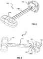
Fig. 1 is a perspective front view showing a syringe driving apparatus not covered by the claims. -
Fig. 2 is a perspective view ofFig. 1 with one part of the housing omitted showing internal structure and components of the apparatus. -
Fig. 3 is a perspective exploded view ofFig. 1 . -
Fig. 4 is a perspective back view ofFig. 1 . -
Fig. 5 is a perspective view ofFig. 4 with part of the housing omitted showing internal structure and components of the apparatus. -
Fig. 6 is a cross sectional view ofFig. 1 when the actuator is at the first position. -
Fig. 7 is a cross sectional view ofFig. 1 when the actuator is at the second position. -
Fig. 8 is a perspective view of the driving member of the apparatus ofFig. 1 . -
Fig. 9 is a perspective view of the driving member ofFig. 8 viewing from another angle. -
Fig. 10 is a perspective view ofFig. 4 omitting the driving member. -
Fig. 11 is a perspective cross sectional view ofFig. 4 omitting the elastic band. -
Fig. 12 is a perspective back view ofFig. 7 . -
Fig. 13 is an enlarged partial view ofFig. 12 . -
Fig. 14 is a perspective of the apparatus ofFig. 1 ready for receiving a syringe. -
Fig. 15 is a perspective of the apparatus ofFig. 1 when a plunger of a syringe is inserted into the housing of the apparatus. -
Fig. 16A is a perspective of the apparatus ofFig. 1 showing a plunger of a syringe is inserted into the housing of the apparatus and omitting the top portion of the housing. -
Fig. 16B is a perspective back view ofFig. 16A . -
Fig. 17 is a partial cross sectional view ofFig. 16B . -
Fig. 18 is a perspective cross sectional view ofFig. 16B . -
Fig. 19 is an enlarged partial view ofFig. 18 . -
Fig. 20 is a perspective view showing the apparatus ofFig. 1 with a syringe attached thereto and ready for infusion operation via the syringe. -
Fig. 21 is a perspective view showing the apparatus ofFig. 1 with a syringe attached thereto and after completion of the infusion operation. -
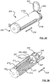
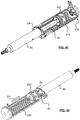
Fig. 22 is a perspective front view showing a syringe driving apparatus according to an embodiment of the present invention. -
Fig. 23 is a perspective view ofFig. 22 with one part of the housing removed showing internal structure and components of the apparatus, in which the spring is in its winded state within the driving member. -
Fig. 24A is a perspective exploded front view ofFig. 22 . -
Fig. 24B is a perspective exploded back view ofFig. 22 . -
Fig. 25 is a perspective back view ofFig. 22 ; -
Fig. 26 is a perspective view ofFig. 25 with one part of the housing omitted showing internal structure and components of the apparatus, in which the spring has been released by a twisting action on the release knob. -
Fig. 27 is a perspective front view ofFig. 22 with one part of the housing omitted showing internal structure and components of the apparatus, where the driving member is positioned adjacent to the front end of the housing. -
Fig. 28 is a perspective front view ofFig. 22 with one part of the housing omitted showing internal structure and components of the apparatus, where the driving member is moved to the back end of the housing. -
Fig. 29 is a perspective view of the slider of the driving member of the apparatus ofFig. 22 before the stem is broken off. -
Fig. 30 is a perspective view of the slider of the driving member of the apparatus ofFig. 22 after stem is broken off. -
Fig. 31 is a perspective view ofFig. 25 showing twisting operation of the knob. -
Fig. 32 is a perspective exploded view ofFig. 31 omitting the upper housing and the assembly of the knob and the housing. -
Fig. 33 is a perspective exploded view ofFig. 31 omitting the upper housing and showing movement of the driving member toward the back end of the housing. -
Fig. 34A is an enlarged partial cross sectional view ofFig. 33 showing the driving member moving toward the back end of the housing. -
Fig. 34B is an enlarged partial cross sectional view ofFig. 33 showing the driving member reached the back end of the housing and engaged and locked to the knob. -
Fig. 34C is an enlarged partial cross sectional view showing the stem being broken off from the casing. -
Fig. 35 is a perspective of the apparatus ofFig. 22 ready for receiving a syringe. -
Fig. 36 is a perspective of the apparatus ofFig. 22 when a plunger of a syringe is inserted into the housing of the apparatus. -
Fig. 37A is a perspective of the apparatus ofFig. 22 showing a plunger of a syringe inserted into the housing of the apparatus and omitting the top portion of the housing. -
Fig. 37B is a perspective back view ofFig. 37A . -
Fig. 38 is a partial enlarged cross sectional view ofFig. 37B omitting the knob. -
Fig. 39 is a perspective cross sectional view ofFig. 37B showing the knob. -
Fig. 40 is an enlarged partial view ofFig. 39 . -
Fig. 41 is a perspective view showing the apparatus ofFig. 22 with a syringe attached thereto and ready for infusion operation via the syringe. -
Fig. 42 is a perspective view showing the apparatus ofFig. 22 with a syringe attached thereto and after completion of the infusion operation. - Referring now to the drawings, a
syringe driving apparatus 100 shown inFigs. 1 to 21 , not covered by the claims, includes ahousing 110, a drivingmember 140 coupled to thehousing 110, and one or more resilient members, e.g. elastic band(s) 160 connecting the drivingmember 140 to thehousing 110.Housing 110 has afront end 102 and aback end 106. Thefront end 102 has a retainingportion 124 configured to receive and fix aflange 84 of asyringe 80 thereto.Housing 110 may include anupper portion 110a and alower portion 110b which is/are generally and interchangeably referred to as housing in the context of this disclosure. - Driving
member 140 has anactuator 142 disposed in thehousing 110, ahandle 146 disposed outside of thehousing 110, and astem 144 connecting theactuator 142 and thehandle 146.Stem 144 is positioned to pass through aback opening 109 formed atback end 106 ofhousing 110. -
Elastic band 160 has two fixingportions middle portion 166 between the two fixingportions portions band 160 around the pin like features and fixed to thehousing 110, and themiddle portion 166 wraps aroundactuator 142 to urge theactuator 142 towards thefront end 102 ofhousing 110. Drivingmember 140 is movable relative thehousing 110 between a first position and a second position. When drivingmember 140 is at the first position, as shown inFig. 6 ,elastic band 160 is less stretched, to keep the actuator 142 closer to thefront end 102 ofhousing 110. Displacement of the drivingmember 140 towards the second position, e.g. along direction D1, as shown inFig. 7 , causes theelastic band 160 to become more stretched, and moves theactuator 142 away from thefront end 102 ofhousing 110. When theactuator 142 is at the second position, the more stretchedelastic band 160 stores elastic energy therein which, in turn, acts againstte actuator 142 and creates a tendency to move theactuator 142 towards thefront end 102 ofhousing 110. - As shown in
Figs. 8 and 9 , drivingmember 140 is formed of an integral part, by injection molding for example. Between actuator 142 and stem 144 there is formed aneck portion 143.Neck portion 143 has a relatively lower strength compared to theactuator 142 and thestem 144, and is configured to present a lower resistance to shear forces and torsional moments. For example,neck portion 143 may have a cross sectional dimension less than that of theactuator 142 and thestem 144. As such,neck portion 143 forms a weak, breakable connection, which can be broken by a rotational twisting of thestem 144 relative to theactuator 142. - A pair of
cantilever arms 145 are formed on thestem 144, adjacent toneck portion 143, and projecting slightly away from thestem 144 and towards theactuator 142.Cantilever arms 145 are elastically deformable with thefree tip 145a flexing relative to thestem 144. - In use, stem 144 is moved along direction D1 (
Figs. 11 ,12 ) away fromhousing 110, by e.g. a user gripping thehandle 146 to pull the drivingmember 140 along direction D1, which displaces theactuator 142 away from thefront end 102 of thehousing 110. During the process of the drivingmember 140 being pulled along direction D1, thestem 144 slides along theback opening 109 formed on theback end 106 of thehousing 110. Meanwhile, theactuator 142 stretches theelastic band 160 due the user's pulling force, resulting in elastic deformation of theelastic band 160 and potential elastic energy stored in theelastic band 160. - As shown in
Figs. 18 and 19 ,housing 110 may have guide members such asridge 1122 formed on the inner surface thereof, along axial direction of thehousing 110.Actuator 142 may havenotch 1422 of complementary shape and dimension as theridge 1122, and engaged toridge 1122 to assist and guide the displacement of theactuator 142 relative to the housing. - When the
actuator 142 is displaced to a position closer theback end 106 of thehousing 110, the cantileveredarms 145 are caused to flex inwardly towards thestem 144. Upon theactuator 142 reaching the second position, stem 144 is pulled completely out of thehousing 100, and thecantilever arms 145 pass through theback opening 109 and resume the initial shape by flex outwardly away from the stem 114. Thefree end 145a of eachcantilever arm 145 are positioned beyond the periphery of theback opening 109 and abut against thehousing 110.Stem 144 is therefore prevented from retracting back into thehousing 110 by which, theactuator 142 is locked at the second position. Meanwhile, the stretchedelastic band 160 exerts a force against theactuator 142 in a direction D2 facing thefront end 102 of thehousing 110. -
Actuator 142 may havevane 1412 formed adjacent to stem 144 to abut against the housing 110 (110b), to ensure the positioning ofactuator 142 when the drivingmember 140 reaching the second position. - As shown in
Figs. 14 and 15 , when it is desired to carry out infusion operation, t asyringe 80 which is filled with liquid medication, is attached to thehousing 110 with theplunger 82 inserted into thehousing 110 through thefront opening 101 at thefront end 102 of thehousing 110, along axial direction D3. The generally oval shapedflange 84 of thesyringe barrel 86 is rotated to become aligned with the retainingportion 124 surrounding thefront opening 101. When flange 84 is brought into contact with the rim of thefront opening 101, theflange 84 is rotated alongcircular direction 80R, to position into thegroove 124a of the retainingportion 124 to attach thesyringe 80 to theapparatus 100. - The dimension of the
housing 110 and theactuator 142 are configured in a manner such that when the portion of theplunger 82 extending out of thebarrel 86 is fully received in thehousing 110, the end surface 82a of theplunger 82 is in contact with or close proximity to theactuator 142, for example with a gap of about 0 to several mm therebetween. -
Syringe 80 is now ready to be connected to a patient or is already connected, via appropriate tubes/conduits (not shown), for infusion of the medication filled in thesyringe 80. - To start infusion, a user twists the
handle 146 relative to thehousing 110, causing thestem 144 together with the cantileveredarms 145 to become broken off from theactuator 142 at theneck portion 143, as shown inFig. 20 . To assist in easy operation of thestem 144 breaking off, housing 110 (110b) may haveribs 104 formed thereon that engages with theactuator 142 when theactuator 142 is at the second position (Fig. 17 ) to prevent actuator 142 from rotating during the twisting of thestem 144. - Upon the
stem 144 and thecantilever arms 145 being broken off from theactuator 142, theactuator 142 is unlocked from thehousing 110, allowing the potential energy stored in theelastic band 160 to release which, in turn, brings theactuator 142 into abutment with theplunger 82. Continuous release of the potential energy from theelastic band 160 presses theactuator 142 against theplunger 82.Plunger 82 is then forced to move into thebarrel 86 to expel the liquid medication out of thesyringe 80 for infusion, as shown inFig. 21 . - In anembodiment, the plunger of a syringe is pushed by the action of a spiral or clock spring acting on a casing that is an integral part of a driving member e.g. a bobbin assembly installed within a housing of the apparatus. The driving member is initially displaced axially along the inner volume space of the housing such that the spiral spring within the casing is winded by the rotation of the casing. The driving member includes a slider movably coupled to the casing. The slider has a shaft to which one end of the spiral spring is affixed. Another end of the spiral spring is affixed to the casing.
- The housing has helical grooves formed on the inner surface. The casing has ridges formed on the outer surface. The ridges engage with the helical grooves such that linear movement of the casing towards the back end of the housing along the longitudinal axis of the housing rotates to the casing about the longitudinal axis to wind the spiral spring. Unwind of the spiral spring causes the rotational movement of the casing relative to the housing about the longitudinal axis, and brings the casing to move linearly along the axial direction back to the front end of the housing.
- The driving member is initially located at the open end/ front end of the housing and a linear displacement of the driving member towards the opposite, back end of the housing will rotate the casing relative to the housing. Rotation of the casing causes the spring to wind, to store elastic potential energy in the spiral spring. The driving member is held at the end of the housing by a release knob that catches on to the stem like protrusion located at the frame of the slider. The stem has a neck portion that represents a weak breakable connection, which can be broken by a rotational twisting of the release knob relative to the frame.
- Referring now to
Figs. 22 to 42 , asyringe driving apparatus 200 according to the invention includes ahousing 210, a driving member orbobbin assembly 220 coupled to thehousing 210, and aknob 290 for connecting, locking and releasing the driving member orbobbin assembly 220 to/from thehousing 210.Housing 210 has afront end 202 and aback end 206. Thefront end 202 has a retainingportion 204 configured to receive and fix aflange 84 of asyringe 80 thereto.Housing 210 may include anupper portion 210a and alower portion 210b which is/are generally and interchangeably referred to as housing in the context of this disclosure.Housing 210 may include amovable flap 203 adjacent to thefront end 202 to cover thefront opening 201 for, e.g. dust-proof purpose. - Driving member or
bobbin assembly 220 includes acasing 240, aslider 260 coupled tocasing 240, ashaft 266 formed on theslider 260 having aframe 262 engaged tohousing 210 and disposed in thecasing 240, and aspiral spring 250 disposed in thecasing 240. Drivingmember 220 may optionally include a seat plate ordisc 230 rotatably attached to theslider 260. Aninner end 256 of thespiral spring 250 is fixed to theshaft 266, and anouter end 254 of thespiral spring 250 is fixed to theinner slot 246 of thecasing 240. Theknob 290 is attached to theback end 206 ofhousing 210, and is rotatable relative tohousing 210. Theslider 260 has astem 264 that has features to enable its fitting with thetubular catch 296 disposed on the inner side of theknob 290.Stem 264 is positioned to pass through aback opening 209 formed atback end 206 ofhousing 210. -
Apparatus 200 may include aclip 207 formed on thehousing 210 for attaching theapparatus 200 to an Intravenous (IV) line so that theapparatus 200 can stay in place before, during and/after the infusion operation.Clip 207 may also be used to pinch the IV line if needed during operation.Clip 207 may be formed integral toknob 290. Alternatively,clip 207 may be formed as an integral tohousing 210 or other portion of theapparatus 200, or a separate part assembled to thehousing 210 or other parts of theapparatus 200. - As shown in
Figs. 24A ,24B ,25 and 26 , thehousing 210 has one or morehelical grooves 218 formed on the inner surface thereof. Thecasing 240 hasridges 248 formed on the outer side surface thereof.Ridges 248 engage thehelical grooves 218 to enable simultaneous rotational and axial movement of thecasing 240 relative to thehousing 210. Due the engagement of theridges 248 andgrooves 218, movement of thecasing 240 alongaxial direction 208 ofhousing 210 from thefront end 202 toward theback end 206 of thehousing 210 rotates thecasing 240 to wind thespiral spring 250 with respect to aspring axis 258, to store potential energy in thespiral spring 250. - As shown in
Figs. 29 and 30 , between theframe 262 and stem 264 there is formed aneck portion 263.Neck portion 263 has a relatively lower strength compared to thestem 264 andframe 262, and is configured to present a lower resistance to shear forces and torsional moments. For example,neck portion 263 may have a cross sectional dimension less than that of thestem 264. As such,neck portion 263 forms a weak, breakable connection between theframe 262 and thestem 264, which can be broken by a rotational twisting of the stem relative to theframe 262. - A pair of
winglets 261 are formed on theframe 262 and engaged tohousing 210, restricting rotational movement of theframe 262 relative tohousing 210, hence accentuating the torsional forces on theneck 263 via thestem 264. - When the
apparatus 200 is at an unused state (Fig. 27 ), e.g. during the shipment and/or storage period, the drivingmember 220 may be positioned adjacent to thefront end 202 of thehousing 210, at which, thespiral spring 250 is at uncoiled or less-coiled state. - In use, driving
member 220 is moved along theaxial direction 208 ofhousing 210 toward theback end 206 of housing 210 (Fig. 28 ), during which, thecasing 240 is rotated to wind thespiral spring 250 to store potential energy in thespiral spring 250. Upon the drivingmember 220 reaching theback end 206 of thehousing 210, as shown inFig. 33 ,34A and 34B , thestem 264 is positioned to pass through theback opening 209 of thehousing 210, and is inserted into and locked to theknob 290 by thetubular catch 296. - As shown in
Fig. 34C , when thestem 264 is broken from theslider 260, by a user twisting theknob 290 relative to thehousing 210 alongrotational direction 294R, theslider 260 is unlocked from thehousing 210. As such, thespiral spring 250 is allowed to release the potential energy stored therein. Thespiral spring 250 produces a torque about its own axis, i.e.spring axis 258, which generates a force F1 exerting against thecasing 240 along peripheral direction. As thecasing 240 is movably coupled to thehousing 210 via the engagement of theridge 248 and thehelical groove 218, the peripheral force F1 is converted into an axial force F2 alongaxial direction 208, to cause displacement of the drivingmember 220 in theaxial direction 208 of thehousing 210. In other words, the axial displacement of the drivingmember 220 arising from a rotational movement of thecasing 240 serves to push the plunger of a syringe attached to thehousing 210 for infusion operation, as illustrated in further detail hereinafter. -
Vane 2642 maybe formed adjacent to stem 264 to abut against the housing 210 (210b), to ensure the positioning ofslider 260 when reaching theback end 206 of thehousing 210. - As shown in
Figs. 35 and 36 , when it is desired to carry out infusion operation, asyringe 80, which is fully or partially filled with liquid medication, is attached to theapparatus 200 with theplunger 82 placing through thefront opening 201 at thefront end 202 of thehousing 210, along axial direction D3, and with theplunger 82 brought into abutment with the drivingmember 220. Further advancement of theplunger 82 along axial direction D3 into thehousing 210 presses against the drivingmember 220, to move the drivingmember 220 towards theback end 206 of thehousing 210, along theaxial direction 208 ofhousing 210. - The generally oval shaped
flange 84 of thesyringe barrel 86 is rotated to become aligned with the retainingportion 224 surrounding thefront opening 201. When flange 84 is brought into contact with the rim of thefront opening 201, theflange 84 is rotated alongcircular direction 80R, to position into the groove 204a of the retainingportion 224 to attach thesyringe 80 to theapparatus 200. - The dimension of the
housing 210 and the drivingmember 220 are configured in a manner such that when theplunger 82 is fully received in thehousing 210, the drivingmember 220 is positioned at theback end 206 of the housing and engaged with theknob 290, and abuts against theplunder 82.Syringe 80 is now ready for infusion operation. - To start infusion, a user twists (along
direction 294R,Fig. 37B ) theknob 290 relative to thehousing 210, to break thestem 264 at theneck 263. Thecasing 240,spiral spring 250 andframe 262 are therefore detached from thestem 264. To assist in easy operation to break thestem 264, thewinglets 267 formed at the sides of theframe 262 engages to theslots 217 formed on thehousing 210 that cross thegrooves 218 of the inner walls of thehousing 210, to prevent theframe 262 from rotating during the twisting of thestem 264. - Once the
stem 264 is broken, thecasing 240 is unlocked from thehousing 210, to allow the potential energy stored in thespiral spring 250 to release, by which, thecasing 240 is driven by thespiral spring 250 to push theplunder 82 into thebarrel 86 to expel the liquid medicine from thesyringe 80 for infusion. - Although embodiments of the present invention have been illustrated in conjunction with the accompanying drawings (in relation with
Figs. 22-42 ) and described in the foregoing detailed description, it should be appreciated that the present invention is not limited to the embodiments disclosed. Therefore, the present invention should be understood to be capable of numerous rearrangements, modifications, alternatives and substitutions without departing from the invention as set forth and recited by the following claims.
Claims (6)
- A syringe driving apparatus comprising:a housing (210) to which a syringe (80) is attachable, the housing (210) having a front end (202), a back end (206) and a compartment between the front end (202) and the back end (206), the compartment is configured to receive a plunger (82) of the syringe (80) therein;a driving member (220) disposed in the compartment, the driving member (220) being movable relative to the housing (210) between the front end (202) and the back end (206);a resilient member (250) connected to the housing (210) and the driving member (220),wherein movement of the driving member (220) towards the back end (206) deforms the resilient member (250) to store potential energy in the resilient member (250), andupon release of the potential energy, the resilient member (250) moves the driving member (220) towards the front end (202) to press the plunger (82) to expel medicine out of the syringe (80)characterized in that the driving member (220) includes a casing (240) and a slider (260) rotatably coupled to the casing (240), the casing (240) being rotatably and slidably coupled to the housing (210), the slider (260) being slidably coupled to the housing (210), wherein the resilient member (250) is a spiral spring having an inner end (256) connected to the slider (260) and an outer end (254) connected to the casing (240), wherein movement of the slider (260) along an axial direction of the housing (210) towards the back end (254) causes the casing (240) to rotate to wind the spiral spring (250) to store potential energy in the spiral spring (250), and upon release of the potential energy, the spiral spring (250) unwinds to move the casing (240) along an axial direction towards the front end (202) to press the plunger (82).
- The apparatus of claim 1, further comprising a seat member movably coupled to the casing to receive the plunger (82).
- The apparatus of claim 2, wherein the casing (240) has ridges (248) formed on an outer surface thereof, the housing (210) having helical grooves (218) formed on an inner surface thereof, wherein the casing (240) is rotatably and slidably coupled to the housing (210) via an engagement of the ridges (248) and the helical grooves (218).
- The apparatus of claim 3, wherein the spiral spring (250) winds and unwinds with respect to a spring axis (258) parallel to the axial direction, and wherein the spiral spring (250) unwinds to generate a first force exerting against the casing (240) along a peripheral direction, and the first force is converted into a second force.
- The apparatus of any of claims 1 to 4, further comprising a locking member (264) connected to the slider (260) and a knob (290) coupled to the housing (210) to engage the locking member (264) to secure the driving member (220) at the back end (206) of the housing (210).
- The apparatus of claim 5, wherein the knob (290) is rotatable relative to the housing (210) to break the locking member (264) from the slider (260) to release the potential energy.
Applications Claiming Priority (2)
| Application Number | Priority Date | Filing Date | Title |
|---|---|---|---|
| US201662437918P | 2016-12-22 | 2016-12-22 | |
| US201762479606P | 2017-03-31 | 2017-03-31 |
Publications (2)
| Publication Number | Publication Date |
|---|---|
| EP3338830A1 EP3338830A1 (en) | 2018-06-27 |
| EP3338830B1 true EP3338830B1 (en) | 2020-02-12 |
Family
ID=60782005
Family Applications (1)
| Application Number | Title | Priority Date | Filing Date |
|---|---|---|---|
| EP17209918.6A Active EP3338830B1 (en) | 2016-12-22 | 2017-12-22 | Syringe driving apparatus |
Country Status (3)
| Country | Link |
|---|---|
| US (1) | US10946146B2 (en) |
| EP (1) | EP3338830B1 (en) |
| CN (1) | CN108379698B (en) |
Families Citing this family (2)
| Publication number | Priority date | Publication date | Assignee | Title |
|---|---|---|---|---|
| AU2019100169A4 (en) | 2019-02-15 | 2019-03-28 | Multigate Medical Products Pty Ltd | A Clip |
| CN110215570A (en) * | 2019-04-19 | 2019-09-10 | 吴银洪 | Full automatic solid sensor body inner injector with mutual exclusion tension stability |
Family Cites Families (9)
| Publication number | Priority date | Publication date | Assignee | Title |
|---|---|---|---|---|
| US5318539A (en) | 1986-10-17 | 1994-06-07 | Alexander G. B. O'Neil | Liquid feeding apparatus utilizing capillary tubing, and syringe driver |
| US20120330275A1 (en) * | 2011-06-23 | 2012-12-27 | Medinvention LLC | Syringe Evacuator |
| EP2703022A1 (en) * | 2012-09-03 | 2014-03-05 | LTS LOHMANN Therapie-Systeme AG | One-off injector with two step disengagement |
| US20150005708A1 (en) * | 2013-06-28 | 2015-01-01 | Juvaplus Sa | Injection device |
| RU2016124541A (en) * | 2013-11-22 | 2017-12-27 | Санофи-Авентис Дойчланд Гмбх | DEVICE WITH A SPRING MECHANISM FOR DELIVERY OF A MEDICINE |
| EP2898910A1 (en) | 2014-01-24 | 2015-07-29 | Freddie Eng Hwee Lee | Elastic band powered fluid delivery apparatus |
| GB201407680D0 (en) | 2014-05-01 | 2014-06-18 | New Injection Systems Ltd | Indicator |
| US10029048B2 (en) * | 2014-05-13 | 2018-07-24 | Allergan, Inc. | High force injection devices |
| SG10201604323YA (en) | 2016-05-30 | 2017-12-28 | Epic Medical Pte Ltd | Spring driven fluid delivery apparatus |
-
2017
- 2017-12-20 US US15/848,528 patent/US10946146B2/en active Active
- 2017-12-22 CN CN201711407605.2A patent/CN108379698B/en not_active Expired - Fee Related
- 2017-12-22 EP EP17209918.6A patent/EP3338830B1/en active Active
Non-Patent Citations (1)
| Title |
|---|
| None * |
Also Published As
| Publication number | Publication date |
|---|---|
| EP3338830A1 (en) | 2018-06-27 |
| CN108379698B (en) | 2022-01-04 |
| US10946146B2 (en) | 2021-03-16 |
| US20180177954A1 (en) | 2018-06-28 |
| CN108379698A (en) | 2018-08-10 |
Similar Documents
| Publication | Publication Date | Title |
|---|---|---|
| US10603431B2 (en) | Dispensing fluid from an infusion pump system | |
| CN107921200B (en) | Medicament delivery device | |
| CN109689131B (en) | Medicament delivery device | |
| JP6085607B2 (en) | Reloadable automatic syringe | |
| TWI646991B (en) | Drive control mechanism and auto injector for injectable fistula | |
| EP2890433B1 (en) | Controlled delivery drive mechanisms for drug delivery pumps | |
| EP1933902B1 (en) | Infusion pump with a drive having a ratchet and pawl combination | |
| EP2819724B1 (en) | Spring force assembly for biasing or actuating stoppers of syringes, injection pen cartridges and the like | |
| JP5667160B2 (en) | Improvements in and about drug delivery devices | |
| US10709841B2 (en) | Injection device | |
| TW200306873A (en) | Collapsible syringe cartridge | |
| US20200114068A1 (en) | Injector device | |
| EP3338830B1 (en) | Syringe driving apparatus | |
| JP2023545482A (en) | Drug delivery member guard lock assembly | |
| WO2018036763A1 (en) | Portable liquid drug delivery device | |
| WO2018166701A1 (en) | Injector device | |
| BRPI0912652A2 (en) | drug delivery device |
Legal Events
| Date | Code | Title | Description |
|---|---|---|---|
| PUAI | Public reference made under article 153(3) epc to a published international application that has entered the european phase |
Free format text: ORIGINAL CODE: 0009012 |
|
| STAA | Information on the status of an ep patent application or granted ep patent |
Free format text: STATUS: THE APPLICATION HAS BEEN PUBLISHED |
|
| AK | Designated contracting states |
Kind code of ref document: A1 Designated state(s): AL AT BE BG CH CY CZ DE DK EE ES FI FR GB GR HR HU IE IS IT LI LT LU LV MC MK MT NL NO PL PT RO RS SE SI SK SM TR |
|
| AX | Request for extension of the european patent |
Extension state: BA ME |
|
| STAA | Information on the status of an ep patent application or granted ep patent |
Free format text: STATUS: REQUEST FOR EXAMINATION WAS MADE |
|
| 17P | Request for examination filed |
Effective date: 20181226 |
|
| RBV | Designated contracting states (corrected) |
Designated state(s): AL AT BE BG CH CY CZ DE DK EE ES FI FR GB GR HR HU IE IS IT LI LT LU LV MC MK MT NL NO PL PT RO RS SE SI SK SM TR |
|
| GRAP | Despatch of communication of intention to grant a patent |
Free format text: ORIGINAL CODE: EPIDOSNIGR1 |
|
| STAA | Information on the status of an ep patent application or granted ep patent |
Free format text: STATUS: GRANT OF PATENT IS INTENDED |
|
| RIC1 | Information provided on ipc code assigned before grant |
Ipc: A61M 5/145 20060101AFI20190731BHEP |
|
| INTG | Intention to grant announced |
Effective date: 20190822 |
|
| RIN1 | Information on inventor provided before grant (corrected) |
Inventor name: LEE, ENG HWEE, FREDDIE |
|
| GRAS | Grant fee paid |
Free format text: ORIGINAL CODE: EPIDOSNIGR3 |
|
| GRAA | (expected) grant |
Free format text: ORIGINAL CODE: 0009210 |
|
| STAA | Information on the status of an ep patent application or granted ep patent |
Free format text: STATUS: THE PATENT HAS BEEN GRANTED |
|
| AK | Designated contracting states |
Kind code of ref document: B1 Designated state(s): AL AT BE BG CH CY CZ DE DK EE ES FI FR GB GR HR HU IE IS IT LI LT LU LV MC MK MT NL NO PL PT RO RS SE SI SK SM TR |
|
| REG | Reference to a national code |
Ref country code: GB Ref legal event code: FG4D |
|
| REG | Reference to a national code |
Ref country code: CH Ref legal event code: EP |
|
| REG | Reference to a national code |
Ref country code: AT Ref legal event code: REF Ref document number: 1231248 Country of ref document: AT Kind code of ref document: T Effective date: 20200215 |
|
| REG | Reference to a national code |
Ref country code: IE Ref legal event code: FG4D |
|
| REG | Reference to a national code |
Ref country code: DE Ref legal event code: R096 Ref document number: 602017011607 Country of ref document: DE |
|
| RAP2 | Party data changed (patent owner data changed or rights of a patent transferred) |
Owner name: EPIC MEDICAL PTE LTD |
|
| PG25 | Lapsed in a contracting state [announced via postgrant information from national office to epo] |
Ref country code: RS Free format text: LAPSE BECAUSE OF FAILURE TO SUBMIT A TRANSLATION OF THE DESCRIPTION OR TO PAY THE FEE WITHIN THE PRESCRIBED TIME-LIMIT Effective date: 20200212 Ref country code: NO Free format text: LAPSE BECAUSE OF FAILURE TO SUBMIT A TRANSLATION OF THE DESCRIPTION OR TO PAY THE FEE WITHIN THE PRESCRIBED TIME-LIMIT Effective date: 20200512 Ref country code: FI Free format text: LAPSE BECAUSE OF FAILURE TO SUBMIT A TRANSLATION OF THE DESCRIPTION OR TO PAY THE FEE WITHIN THE PRESCRIBED TIME-LIMIT Effective date: 20200212 |
|
| REG | Reference to a national code |
Ref country code: LT Ref legal event code: MG4D |
|
| REG | Reference to a national code |
Ref country code: NL Ref legal event code: MP Effective date: 20200212 |
|
| PG25 | Lapsed in a contracting state [announced via postgrant information from national office to epo] |
Ref country code: IS Free format text: LAPSE BECAUSE OF FAILURE TO SUBMIT A TRANSLATION OF THE DESCRIPTION OR TO PAY THE FEE WITHIN THE PRESCRIBED TIME-LIMIT Effective date: 20200612 Ref country code: BG Free format text: LAPSE BECAUSE OF FAILURE TO SUBMIT A TRANSLATION OF THE DESCRIPTION OR TO PAY THE FEE WITHIN THE PRESCRIBED TIME-LIMIT Effective date: 20200512 Ref country code: HR Free format text: LAPSE BECAUSE OF FAILURE TO SUBMIT A TRANSLATION OF THE DESCRIPTION OR TO PAY THE FEE WITHIN THE PRESCRIBED TIME-LIMIT Effective date: 20200212 Ref country code: GR Free format text: LAPSE BECAUSE OF FAILURE TO SUBMIT A TRANSLATION OF THE DESCRIPTION OR TO PAY THE FEE WITHIN THE PRESCRIBED TIME-LIMIT Effective date: 20200513 Ref country code: LV Free format text: LAPSE BECAUSE OF FAILURE TO SUBMIT A TRANSLATION OF THE DESCRIPTION OR TO PAY THE FEE WITHIN THE PRESCRIBED TIME-LIMIT Effective date: 20200212 Ref country code: SE Free format text: LAPSE BECAUSE OF FAILURE TO SUBMIT A TRANSLATION OF THE DESCRIPTION OR TO PAY THE FEE WITHIN THE PRESCRIBED TIME-LIMIT Effective date: 20200212 |
|
| PG25 | Lapsed in a contracting state [announced via postgrant information from national office to epo] |
Ref country code: NL Free format text: LAPSE BECAUSE OF FAILURE TO SUBMIT A TRANSLATION OF THE DESCRIPTION OR TO PAY THE FEE WITHIN THE PRESCRIBED TIME-LIMIT Effective date: 20200212 |
|
| PG25 | Lapsed in a contracting state [announced via postgrant information from national office to epo] |
Ref country code: PT Free format text: LAPSE BECAUSE OF FAILURE TO SUBMIT A TRANSLATION OF THE DESCRIPTION OR TO PAY THE FEE WITHIN THE PRESCRIBED TIME-LIMIT Effective date: 20200705 Ref country code: DK Free format text: LAPSE BECAUSE OF FAILURE TO SUBMIT A TRANSLATION OF THE DESCRIPTION OR TO PAY THE FEE WITHIN THE PRESCRIBED TIME-LIMIT Effective date: 20200212 Ref country code: ES Free format text: LAPSE BECAUSE OF FAILURE TO SUBMIT A TRANSLATION OF THE DESCRIPTION OR TO PAY THE FEE WITHIN THE PRESCRIBED TIME-LIMIT Effective date: 20200212 Ref country code: EE Free format text: LAPSE BECAUSE OF FAILURE TO SUBMIT A TRANSLATION OF THE DESCRIPTION OR TO PAY THE FEE WITHIN THE PRESCRIBED TIME-LIMIT Effective date: 20200212 Ref country code: SM Free format text: LAPSE BECAUSE OF FAILURE TO SUBMIT A TRANSLATION OF THE DESCRIPTION OR TO PAY THE FEE WITHIN THE PRESCRIBED TIME-LIMIT Effective date: 20200212 Ref country code: RO Free format text: LAPSE BECAUSE OF FAILURE TO SUBMIT A TRANSLATION OF THE DESCRIPTION OR TO PAY THE FEE WITHIN THE PRESCRIBED TIME-LIMIT Effective date: 20200212 Ref country code: SK Free format text: LAPSE BECAUSE OF FAILURE TO SUBMIT A TRANSLATION OF THE DESCRIPTION OR TO PAY THE FEE WITHIN THE PRESCRIBED TIME-LIMIT Effective date: 20200212 Ref country code: CZ Free format text: LAPSE BECAUSE OF FAILURE TO SUBMIT A TRANSLATION OF THE DESCRIPTION OR TO PAY THE FEE WITHIN THE PRESCRIBED TIME-LIMIT Effective date: 20200212 Ref country code: LT Free format text: LAPSE BECAUSE OF FAILURE TO SUBMIT A TRANSLATION OF THE DESCRIPTION OR TO PAY THE FEE WITHIN THE PRESCRIBED TIME-LIMIT Effective date: 20200212 |
|
| REG | Reference to a national code |
Ref country code: DE Ref legal event code: R097 Ref document number: 602017011607 Country of ref document: DE |
|
| REG | Reference to a national code |
Ref country code: AT Ref legal event code: MK05 Ref document number: 1231248 Country of ref document: AT Kind code of ref document: T Effective date: 20200212 |
|
| PLBE | No opposition filed within time limit |
Free format text: ORIGINAL CODE: 0009261 |
|
| STAA | Information on the status of an ep patent application or granted ep patent |
Free format text: STATUS: NO OPPOSITION FILED WITHIN TIME LIMIT |
|
| 26N | No opposition filed |
Effective date: 20201113 |
|
| PG25 | Lapsed in a contracting state [announced via postgrant information from national office to epo] |
Ref country code: IT Free format text: LAPSE BECAUSE OF FAILURE TO SUBMIT A TRANSLATION OF THE DESCRIPTION OR TO PAY THE FEE WITHIN THE PRESCRIBED TIME-LIMIT Effective date: 20200212 Ref country code: AT Free format text: LAPSE BECAUSE OF FAILURE TO SUBMIT A TRANSLATION OF THE DESCRIPTION OR TO PAY THE FEE WITHIN THE PRESCRIBED TIME-LIMIT Effective date: 20200212 |
|
| PG25 | Lapsed in a contracting state [announced via postgrant information from national office to epo] |
Ref country code: PL Free format text: LAPSE BECAUSE OF FAILURE TO SUBMIT A TRANSLATION OF THE DESCRIPTION OR TO PAY THE FEE WITHIN THE PRESCRIBED TIME-LIMIT Effective date: 20200212 Ref country code: SI Free format text: LAPSE BECAUSE OF FAILURE TO SUBMIT A TRANSLATION OF THE DESCRIPTION OR TO PAY THE FEE WITHIN THE PRESCRIBED TIME-LIMIT Effective date: 20200212 |
|
| PG25 | Lapsed in a contracting state [announced via postgrant information from national office to epo] |
Ref country code: MC Free format text: LAPSE BECAUSE OF FAILURE TO SUBMIT A TRANSLATION OF THE DESCRIPTION OR TO PAY THE FEE WITHIN THE PRESCRIBED TIME-LIMIT Effective date: 20200212 |
|
| PG25 | Lapsed in a contracting state [announced via postgrant information from national office to epo] |
Ref country code: LU Free format text: LAPSE BECAUSE OF NON-PAYMENT OF DUE FEES Effective date: 20201222 |
|
| PG25 | Lapsed in a contracting state [announced via postgrant information from national office to epo] |
Ref country code: TR Free format text: LAPSE BECAUSE OF FAILURE TO SUBMIT A TRANSLATION OF THE DESCRIPTION OR TO PAY THE FEE WITHIN THE PRESCRIBED TIME-LIMIT Effective date: 20200212 Ref country code: MT Free format text: LAPSE BECAUSE OF FAILURE TO SUBMIT A TRANSLATION OF THE DESCRIPTION OR TO PAY THE FEE WITHIN THE PRESCRIBED TIME-LIMIT Effective date: 20200212 Ref country code: CY Free format text: LAPSE BECAUSE OF FAILURE TO SUBMIT A TRANSLATION OF THE DESCRIPTION OR TO PAY THE FEE WITHIN THE PRESCRIBED TIME-LIMIT Effective date: 20200212 |
|
| PG25 | Lapsed in a contracting state [announced via postgrant information from national office to epo] |
Ref country code: MK Free format text: LAPSE BECAUSE OF FAILURE TO SUBMIT A TRANSLATION OF THE DESCRIPTION OR TO PAY THE FEE WITHIN THE PRESCRIBED TIME-LIMIT Effective date: 20200212 Ref country code: AL Free format text: LAPSE BECAUSE OF FAILURE TO SUBMIT A TRANSLATION OF THE DESCRIPTION OR TO PAY THE FEE WITHIN THE PRESCRIBED TIME-LIMIT Effective date: 20200212 |
|
| PGFP | Annual fee paid to national office [announced via postgrant information from national office to epo] |
Ref country code: BE Payment date: 20221216 Year of fee payment: 6 |
|
| PGFP | Annual fee paid to national office [announced via postgrant information from national office to epo] |
Ref country code: CH Payment date: 20221229 Year of fee payment: 6 |
|
| PGFP | Annual fee paid to national office [announced via postgrant information from national office to epo] |
Ref country code: DE Payment date: 20221229 Year of fee payment: 6 |
|
| PGFP | Annual fee paid to national office [announced via postgrant information from national office to epo] |
Ref country code: GB Payment date: 20231218 Year of fee payment: 7 |
|
| PGFP | Annual fee paid to national office [announced via postgrant information from national office to epo] |
Ref country code: IE Payment date: 20231217 Year of fee payment: 7 Ref country code: FR Payment date: 20231220 Year of fee payment: 7 |
|
| PGFP | Annual fee paid to national office [announced via postgrant information from national office to epo] |
Ref country code: BE Payment date: 20231218 Year of fee payment: 7 |