EP3338736B1 - Selbstschliessende vorrichtung - Google Patents
Selbstschliessende vorrichtung Download PDFInfo
- Publication number
- EP3338736B1 EP3338736B1 EP18150646.0A EP18150646A EP3338736B1 EP 3338736 B1 EP3338736 B1 EP 3338736B1 EP 18150646 A EP18150646 A EP 18150646A EP 3338736 B1 EP3338736 B1 EP 3338736B1
- Authority
- EP
- European Patent Office
- Prior art keywords
- port
- access port
- access
- tubular
- bands
- Prior art date
- Legal status (The legal status is an assumption and is not a legal conclusion. Google has not performed a legal analysis and makes no representation as to the accuracy of the status listed.)
- Active
Links
- 239000000463 material Substances 0.000 claims description 114
- 239000004744 fabric Substances 0.000 claims description 27
- 238000007789 sealing Methods 0.000 claims description 15
- 238000009958 sewing Methods 0.000 claims description 8
- 210000000056 organ Anatomy 0.000 claims description 7
- 239000013536 elastomeric material Substances 0.000 claims description 5
- 210000001519 tissue Anatomy 0.000 description 30
- 238000000034 method Methods 0.000 description 25
- 229920001296 polysiloxane Polymers 0.000 description 22
- 239000000853 adhesive Substances 0.000 description 18
- 230000001070 adhesive effect Effects 0.000 description 18
- 206010016717 Fistula Diseases 0.000 description 12
- 230000003890 fistula Effects 0.000 description 12
- 238000000502 dialysis Methods 0.000 description 11
- 230000005294 ferromagnetic effect Effects 0.000 description 9
- 210000003462 vein Anatomy 0.000 description 9
- 210000004204 blood vessel Anatomy 0.000 description 8
- 229910001000 nickel titanium Inorganic materials 0.000 description 8
- 230000002792 vascular Effects 0.000 description 8
- 208000020832 chronic kidney disease Diseases 0.000 description 7
- 238000001631 haemodialysis Methods 0.000 description 7
- 230000000322 hemodialysis Effects 0.000 description 7
- HLXZNVUGXRDIFK-UHFFFAOYSA-N nickel titanium Chemical compound [Ti].[Ti].[Ti].[Ti].[Ti].[Ti].[Ti].[Ti].[Ti].[Ti].[Ti].[Ni].[Ni].[Ni].[Ni].[Ni].[Ni].[Ni].[Ni].[Ni].[Ni].[Ni].[Ni].[Ni].[Ni] HLXZNVUGXRDIFK-UHFFFAOYSA-N 0.000 description 7
- 201000000523 end stage renal failure Diseases 0.000 description 6
- 238000002513 implantation Methods 0.000 description 6
- 230000007704 transition Effects 0.000 description 6
- 210000001367 artery Anatomy 0.000 description 5
- 238000005520 cutting process Methods 0.000 description 5
- 238000003698 laser cutting Methods 0.000 description 5
- 238000011282 treatment Methods 0.000 description 5
- 238000003466 welding Methods 0.000 description 5
- 229920000295 expanded polytetrafluoroethylene Polymers 0.000 description 4
- 239000007943 implant Substances 0.000 description 4
- 210000003734 kidney Anatomy 0.000 description 4
- 229910052751 metal Inorganic materials 0.000 description 4
- 239000002184 metal Substances 0.000 description 4
- 230000035515 penetration Effects 0.000 description 4
- 230000035882 stress Effects 0.000 description 4
- 208000009087 False Aneurysm Diseases 0.000 description 3
- 208000027418 Wounds and injury Diseases 0.000 description 3
- 230000003872 anastomosis Effects 0.000 description 3
- 238000005266 casting Methods 0.000 description 3
- 230000006835 compression Effects 0.000 description 3
- 238000007906 compression Methods 0.000 description 3
- 238000011065 in-situ storage Methods 0.000 description 3
- 238000003780 insertion Methods 0.000 description 3
- 230000037431 insertion Effects 0.000 description 3
- 238000003754 machining Methods 0.000 description 3
- 238000000465 moulding Methods 0.000 description 3
- 238000007634 remodeling Methods 0.000 description 3
- 230000008439 repair process Effects 0.000 description 3
- 229910001220 stainless steel Inorganic materials 0.000 description 3
- 239000010935 stainless steel Substances 0.000 description 3
- 208000032843 Hemorrhage Diseases 0.000 description 2
- 208000007536 Thrombosis Diseases 0.000 description 2
- 206010048975 Vascular pseudoaneurysm Diseases 0.000 description 2
- 206010052428 Wound Diseases 0.000 description 2
- 238000002399 angioplasty Methods 0.000 description 2
- 230000002421 anti-septic effect Effects 0.000 description 2
- 239000012620 biological material Substances 0.000 description 2
- 208000034158 bleeding Diseases 0.000 description 2
- 230000000740 bleeding effect Effects 0.000 description 2
- 230000015556 catabolic process Effects 0.000 description 2
- 239000011248 coating agent Substances 0.000 description 2
- 238000000576 coating method Methods 0.000 description 2
- 239000002131 composite material Substances 0.000 description 2
- 238000006731 degradation reaction Methods 0.000 description 2
- -1 e.g. Substances 0.000 description 2
- 239000000835 fiber Substances 0.000 description 2
- 206010020718 hyperplasia Diseases 0.000 description 2
- 208000015181 infectious disease Diseases 0.000 description 2
- 210000005240 left ventricle Anatomy 0.000 description 2
- 230000005291 magnetic effect Effects 0.000 description 2
- 238000012986 modification Methods 0.000 description 2
- 230000004048 modification Effects 0.000 description 2
- 230000000737 periodic effect Effects 0.000 description 2
- 229920000728 polyester Polymers 0.000 description 2
- 229920000642 polymer Polymers 0.000 description 2
- 230000008569 process Effects 0.000 description 2
- 238000005096 rolling process Methods 0.000 description 2
- 239000007787 solid Substances 0.000 description 2
- 238000009987 spinning Methods 0.000 description 2
- 239000000758 substrate Substances 0.000 description 2
- 238000004381 surface treatment Methods 0.000 description 2
- 229910000684 Cobalt-chrome Inorganic materials 0.000 description 1
- 206010020772 Hypertension Diseases 0.000 description 1
- 208000012266 Needlestick injury Diseases 0.000 description 1
- 208000008883 Patent Foramen Ovale Diseases 0.000 description 1
- 239000002202 Polyethylene glycol Substances 0.000 description 1
- 206010053648 Vascular occlusion Diseases 0.000 description 1
- WAIPAZQMEIHHTJ-UHFFFAOYSA-N [Cr].[Co] Chemical compound [Cr].[Co] WAIPAZQMEIHHTJ-UHFFFAOYSA-N 0.000 description 1
- 210000001015 abdomen Anatomy 0.000 description 1
- 210000003815 abdominal wall Anatomy 0.000 description 1
- 230000001154 acute effect Effects 0.000 description 1
- 230000032683 aging Effects 0.000 description 1
- 230000002965 anti-thrombogenic effect Effects 0.000 description 1
- 210000001765 aortic valve Anatomy 0.000 description 1
- 230000004872 arterial blood pressure Effects 0.000 description 1
- 230000003190 augmentative effect Effects 0.000 description 1
- 230000004323 axial length Effects 0.000 description 1
- 230000004888 barrier function Effects 0.000 description 1
- 238000005452 bending Methods 0.000 description 1
- 239000000560 biocompatible material Substances 0.000 description 1
- 230000015572 biosynthetic process Effects 0.000 description 1
- 239000003795 chemical substances by application Substances 0.000 description 1
- 239000010952 cobalt-chrome Substances 0.000 description 1
- 210000002808 connective tissue Anatomy 0.000 description 1
- 230000008878 coupling Effects 0.000 description 1
- 238000010168 coupling process Methods 0.000 description 1
- 238000005859 coupling reaction Methods 0.000 description 1
- 230000006378 damage Effects 0.000 description 1
- 238000013461 design Methods 0.000 description 1
- 206010012601 diabetes mellitus Diseases 0.000 description 1
- 238000002405 diagnostic procedure Methods 0.000 description 1
- 229920001971 elastomer Polymers 0.000 description 1
- 239000000806 elastomer Substances 0.000 description 1
- 208000028208 end stage renal disease Diseases 0.000 description 1
- 238000005530 etching Methods 0.000 description 1
- 239000006260 foam Substances 0.000 description 1
- 210000000245 forearm Anatomy 0.000 description 1
- 238000010438 heat treatment Methods 0.000 description 1
- 230000023597 hemostasis Effects 0.000 description 1
- 208000014674 injury Diseases 0.000 description 1
- 230000000968 intestinal effect Effects 0.000 description 1
- 238000010030 laminating Methods 0.000 description 1
- 238000004519 manufacturing process Methods 0.000 description 1
- 238000010297 mechanical methods and process Methods 0.000 description 1
- 238000002844 melting Methods 0.000 description 1
- 230000008018 melting Effects 0.000 description 1
- 230000005012 migration Effects 0.000 description 1
- 238000013508 migration Methods 0.000 description 1
- RVTZCBVAJQQJTK-UHFFFAOYSA-N oxygen(2-);zirconium(4+) Chemical compound [O-2].[O-2].[Zr+4] RVTZCBVAJQQJTK-UHFFFAOYSA-N 0.000 description 1
- 230000002093 peripheral effect Effects 0.000 description 1
- 239000004033 plastic Substances 0.000 description 1
- 229920003023 plastic Polymers 0.000 description 1
- 238000005498 polishing Methods 0.000 description 1
- 229920001223 polyethylene glycol Polymers 0.000 description 1
- 229920001343 polytetrafluoroethylene Polymers 0.000 description 1
- 239000004810 polytetrafluoroethylene Substances 0.000 description 1
- 239000011148 porous material Substances 0.000 description 1
- 230000000069 prophylactic effect Effects 0.000 description 1
- 230000002787 reinforcement Effects 0.000 description 1
- 238000000926 separation method Methods 0.000 description 1
- 239000012781 shape memory material Substances 0.000 description 1
- 238000005476 soldering Methods 0.000 description 1
- 238000010561 standard procedure Methods 0.000 description 1
- 229920002994 synthetic fiber Polymers 0.000 description 1
- 210000004876 tela submucosa Anatomy 0.000 description 1
- 238000002560 therapeutic procedure Methods 0.000 description 1
- 238000013151 thrombectomy Methods 0.000 description 1
- 238000002604 ultrasonography Methods 0.000 description 1
- 208000021331 vascular occlusion disease Diseases 0.000 description 1
- 238000007631 vascular surgery Methods 0.000 description 1
- 210000005166 vasculature Anatomy 0.000 description 1
- 238000012800 visualization Methods 0.000 description 1
- 238000004804 winding Methods 0.000 description 1
Images


Classifications
-
- A—HUMAN NECESSITIES
- A61—MEDICAL OR VETERINARY SCIENCE; HYGIENE
- A61B—DIAGNOSIS; SURGERY; IDENTIFICATION
- A61B17/00—Surgical instruments, devices or methods, e.g. tourniquets
- A61B17/0057—Implements for plugging an opening in the wall of a hollow or tubular organ, e.g. for sealing a vessel puncture or closing a cardiac septal defect
-
- A—HUMAN NECESSITIES
- A61—MEDICAL OR VETERINARY SCIENCE; HYGIENE
- A61B—DIAGNOSIS; SURGERY; IDENTIFICATION
- A61B17/00—Surgical instruments, devices or methods, e.g. tourniquets
- A61B17/11—Surgical instruments, devices or methods, e.g. tourniquets for performing anastomosis; Buttons for anastomosis
-
- A—HUMAN NECESSITIES
- A61—MEDICAL OR VETERINARY SCIENCE; HYGIENE
- A61B—DIAGNOSIS; SURGERY; IDENTIFICATION
- A61B17/00—Surgical instruments, devices or methods, e.g. tourniquets
- A61B17/34—Trocars; Puncturing needles
- A61B17/3403—Needle locating or guiding means
-
- A—HUMAN NECESSITIES
- A61—MEDICAL OR VETERINARY SCIENCE; HYGIENE
- A61B—DIAGNOSIS; SURGERY; IDENTIFICATION
- A61B90/00—Instruments, implements or accessories specially adapted for surgery or diagnosis and not covered by any of the groups A61B1/00 - A61B50/00, e.g. for luxation treatment or for protecting wound edges
- A61B90/39—Markers, e.g. radio-opaque or breast lesions markers
-
- A—HUMAN NECESSITIES
- A61—MEDICAL OR VETERINARY SCIENCE; HYGIENE
- A61M—DEVICES FOR INTRODUCING MEDIA INTO, OR ONTO, THE BODY; DEVICES FOR TRANSDUCING BODY MEDIA OR FOR TAKING MEDIA FROM THE BODY; DEVICES FOR PRODUCING OR ENDING SLEEP OR STUPOR
- A61M1/00—Suction or pumping devices for medical purposes; Devices for carrying-off, for treatment of, or for carrying-over, body-liquids; Drainage systems
- A61M1/36—Other treatment of blood in a by-pass of the natural circulatory system, e.g. temperature adaptation, irradiation ; Extra-corporeal blood circuits
- A61M1/3621—Extra-corporeal blood circuits
- A61M1/3653—Interfaces between patient blood circulation and extra-corporal blood circuit
- A61M1/3655—Arterio-venous shunts or fistulae
-
- A—HUMAN NECESSITIES
- A61—MEDICAL OR VETERINARY SCIENCE; HYGIENE
- A61M—DEVICES FOR INTRODUCING MEDIA INTO, OR ONTO, THE BODY; DEVICES FOR TRANSDUCING BODY MEDIA OR FOR TAKING MEDIA FROM THE BODY; DEVICES FOR PRODUCING OR ENDING SLEEP OR STUPOR
- A61M39/00—Tubes, tube connectors, tube couplings, valves, access sites or the like, specially adapted for medical use
- A61M39/02—Access sites
- A61M39/0247—Semi-permanent or permanent transcutaneous or percutaneous access sites to the inside of the body
-
- A—HUMAN NECESSITIES
- A61—MEDICAL OR VETERINARY SCIENCE; HYGIENE
- A61B—DIAGNOSIS; SURGERY; IDENTIFICATION
- A61B17/00—Surgical instruments, devices or methods, e.g. tourniquets
- A61B17/0057—Implements for plugging an opening in the wall of a hollow or tubular organ, e.g. for sealing a vessel puncture or closing a cardiac septal defect
- A61B2017/00575—Implements for plugging an opening in the wall of a hollow or tubular organ, e.g. for sealing a vessel puncture or closing a cardiac septal defect for closure at remote site, e.g. closing atrial septum defects
- A61B2017/00592—Elastic or resilient implements
-
- A—HUMAN NECESSITIES
- A61—MEDICAL OR VETERINARY SCIENCE; HYGIENE
- A61B—DIAGNOSIS; SURGERY; IDENTIFICATION
- A61B17/00—Surgical instruments, devices or methods, e.g. tourniquets
- A61B17/0057—Implements for plugging an opening in the wall of a hollow or tubular organ, e.g. for sealing a vessel puncture or closing a cardiac septal defect
- A61B2017/00575—Implements for plugging an opening in the wall of a hollow or tubular organ, e.g. for sealing a vessel puncture or closing a cardiac septal defect for closure at remote site, e.g. closing atrial septum defects
- A61B2017/00597—Implements comprising a membrane
-
- A—HUMAN NECESSITIES
- A61—MEDICAL OR VETERINARY SCIENCE; HYGIENE
- A61B—DIAGNOSIS; SURGERY; IDENTIFICATION
- A61B17/00—Surgical instruments, devices or methods, e.g. tourniquets
- A61B17/0057—Implements for plugging an opening in the wall of a hollow or tubular organ, e.g. for sealing a vessel puncture or closing a cardiac septal defect
- A61B2017/00676—Implements for plugging an opening in the wall of a hollow or tubular organ, e.g. for sealing a vessel puncture or closing a cardiac septal defect promotion of self-sealing of the puncture
-
- A—HUMAN NECESSITIES
- A61—MEDICAL OR VETERINARY SCIENCE; HYGIENE
- A61B—DIAGNOSIS; SURGERY; IDENTIFICATION
- A61B17/00—Surgical instruments, devices or methods, e.g. tourniquets
- A61B2017/00831—Material properties
- A61B2017/00862—Material properties elastic or resilient
-
- A—HUMAN NECESSITIES
- A61—MEDICAL OR VETERINARY SCIENCE; HYGIENE
- A61B—DIAGNOSIS; SURGERY; IDENTIFICATION
- A61B17/00—Surgical instruments, devices or methods, e.g. tourniquets
- A61B2017/00831—Material properties
- A61B2017/00867—Material properties shape memory effect
-
- A—HUMAN NECESSITIES
- A61—MEDICAL OR VETERINARY SCIENCE; HYGIENE
- A61B—DIAGNOSIS; SURGERY; IDENTIFICATION
- A61B17/00—Surgical instruments, devices or methods, e.g. tourniquets
- A61B2017/00831—Material properties
- A61B2017/00876—Material properties magnetic
-
- A—HUMAN NECESSITIES
- A61—MEDICAL OR VETERINARY SCIENCE; HYGIENE
- A61B—DIAGNOSIS; SURGERY; IDENTIFICATION
- A61B17/00—Surgical instruments, devices or methods, e.g. tourniquets
- A61B17/11—Surgical instruments, devices or methods, e.g. tourniquets for performing anastomosis; Buttons for anastomosis
- A61B2017/1107—Surgical instruments, devices or methods, e.g. tourniquets for performing anastomosis; Buttons for anastomosis for blood vessels
-
- A—HUMAN NECESSITIES
- A61—MEDICAL OR VETERINARY SCIENCE; HYGIENE
- A61B—DIAGNOSIS; SURGERY; IDENTIFICATION
- A61B17/00—Surgical instruments, devices or methods, e.g. tourniquets
- A61B17/11—Surgical instruments, devices or methods, e.g. tourniquets for performing anastomosis; Buttons for anastomosis
- A61B2017/1135—End-to-side connections, e.g. T- or Y-connections
-
- A—HUMAN NECESSITIES
- A61—MEDICAL OR VETERINARY SCIENCE; HYGIENE
- A61B—DIAGNOSIS; SURGERY; IDENTIFICATION
- A61B17/00—Surgical instruments, devices or methods, e.g. tourniquets
- A61B17/12—Surgical instruments, devices or methods, e.g. tourniquets for ligaturing or otherwise compressing tubular parts of the body, e.g. blood vessels, umbilical cord
- A61B2017/12004—Surgical instruments, devices or methods, e.g. tourniquets for ligaturing or otherwise compressing tubular parts of the body, e.g. blood vessels, umbilical cord for haemostasis, for prevention of bleeding
-
- A—HUMAN NECESSITIES
- A61—MEDICAL OR VETERINARY SCIENCE; HYGIENE
- A61B—DIAGNOSIS; SURGERY; IDENTIFICATION
- A61B90/00—Instruments, implements or accessories specially adapted for surgery or diagnosis and not covered by any of the groups A61B1/00 - A61B50/00, e.g. for luxation treatment or for protecting wound edges
- A61B90/39—Markers, e.g. radio-opaque or breast lesions markers
- A61B2090/3962—Markers, e.g. radio-opaque or breast lesions markers palpable
-
- A—HUMAN NECESSITIES
- A61—MEDICAL OR VETERINARY SCIENCE; HYGIENE
- A61B—DIAGNOSIS; SURGERY; IDENTIFICATION
- A61B90/00—Instruments, implements or accessories specially adapted for surgery or diagnosis and not covered by any of the groups A61B1/00 - A61B50/00, e.g. for luxation treatment or for protecting wound edges
- A61B90/39—Markers, e.g. radio-opaque or breast lesions markers
- A61B2090/3966—Radiopaque markers visible in an X-ray image
-
- A—HUMAN NECESSITIES
- A61—MEDICAL OR VETERINARY SCIENCE; HYGIENE
- A61F—FILTERS IMPLANTABLE INTO BLOOD VESSELS; PROSTHESES; DEVICES PROVIDING PATENCY TO, OR PREVENTING COLLAPSING OF, TUBULAR STRUCTURES OF THE BODY, e.g. STENTS; ORTHOPAEDIC, NURSING OR CONTRACEPTIVE DEVICES; FOMENTATION; TREATMENT OR PROTECTION OF EYES OR EARS; BANDAGES, DRESSINGS OR ABSORBENT PADS; FIRST-AID KITS
- A61F2/00—Filters implantable into blood vessels; Prostheses, i.e. artificial substitutes or replacements for parts of the body; Appliances for connecting them with the body; Devices providing patency to, or preventing collapsing of, tubular structures of the body, e.g. stents
- A61F2/02—Prostheses implantable into the body
- A61F2/04—Hollow or tubular parts of organs, e.g. bladders, tracheae, bronchi or bile ducts
- A61F2/06—Blood vessels
- A61F2/064—Blood vessels with special features to facilitate anastomotic coupling
-
- A—HUMAN NECESSITIES
- A61—MEDICAL OR VETERINARY SCIENCE; HYGIENE
- A61F—FILTERS IMPLANTABLE INTO BLOOD VESSELS; PROSTHESES; DEVICES PROVIDING PATENCY TO, OR PREVENTING COLLAPSING OF, TUBULAR STRUCTURES OF THE BODY, e.g. STENTS; ORTHOPAEDIC, NURSING OR CONTRACEPTIVE DEVICES; FOMENTATION; TREATMENT OR PROTECTION OF EYES OR EARS; BANDAGES, DRESSINGS OR ABSORBENT PADS; FIRST-AID KITS
- A61F2210/00—Particular material properties of prostheses classified in groups A61F2/00 - A61F2/26 or A61F2/82 or A61F9/00 or A61F11/00 or subgroups thereof
- A61F2210/009—Particular material properties of prostheses classified in groups A61F2/00 - A61F2/26 or A61F2/82 or A61F9/00 or A61F11/00 or subgroups thereof magnetic
-
- A—HUMAN NECESSITIES
- A61—MEDICAL OR VETERINARY SCIENCE; HYGIENE
- A61M—DEVICES FOR INTRODUCING MEDIA INTO, OR ONTO, THE BODY; DEVICES FOR TRANSDUCING BODY MEDIA OR FOR TAKING MEDIA FROM THE BODY; DEVICES FOR PRODUCING OR ENDING SLEEP OR STUPOR
- A61M39/00—Tubes, tube connectors, tube couplings, valves, access sites or the like, specially adapted for medical use
- A61M39/02—Access sites
- A61M39/0247—Semi-permanent or permanent transcutaneous or percutaneous access sites to the inside of the body
- A61M2039/0258—Semi-permanent or permanent transcutaneous or percutaneous access sites to the inside of the body for vascular access, e.g. blood stream access
-
- A—HUMAN NECESSITIES
- A61—MEDICAL OR VETERINARY SCIENCE; HYGIENE
- A61M—DEVICES FOR INTRODUCING MEDIA INTO, OR ONTO, THE BODY; DEVICES FOR TRANSDUCING BODY MEDIA OR FOR TAKING MEDIA FROM THE BODY; DEVICES FOR PRODUCING OR ENDING SLEEP OR STUPOR
- A61M39/00—Tubes, tube connectors, tube couplings, valves, access sites or the like, specially adapted for medical use
- A61M39/02—Access sites
- A61M39/0247—Semi-permanent or permanent transcutaneous or percutaneous access sites to the inside of the body
- A61M2039/0261—Means for anchoring port to the body, or ports having a special shape or being made of a specific material to allow easy implantation/integration in the body
-
- A—HUMAN NECESSITIES
- A61—MEDICAL OR VETERINARY SCIENCE; HYGIENE
- A61M—DEVICES FOR INTRODUCING MEDIA INTO, OR ONTO, THE BODY; DEVICES FOR TRANSDUCING BODY MEDIA OR FOR TAKING MEDIA FROM THE BODY; DEVICES FOR PRODUCING OR ENDING SLEEP OR STUPOR
- A61M39/00—Tubes, tube connectors, tube couplings, valves, access sites or the like, specially adapted for medical use
- A61M39/02—Access sites
- A61M39/0247—Semi-permanent or permanent transcutaneous or percutaneous access sites to the inside of the body
- A61M2039/0291—Semi-permanent or permanent transcutaneous or percutaneous access sites to the inside of the body method or device for implanting it in the body
Definitions
- the field of the invention generally relates to self-closing devices that are implantable within a patient's body and to apparatus and systems including such self-closing devices.
- the present invention may include self-closing tubular structures, cuffs, or patches, and/or grafts that include resealable access ports or regions including self-closing tubular structures, and/or may include systems for implanting such self-closing structures and/or grafts.
- ESRD end stage renal disease
- the two primary modes of treatment are kidney transplant and hemodialysis. Due to the shortage of available transplant kidneys, approximately seventy percent (70%) of people with ESRD undergo hemodialysis (USRDS 2008) for life or until a transplant kidney becomes available. To facilitate the frequent, periodic treatments, patients must undergo vascular surgery to prepare their artery and vein, typically in their forearm, for dialysis.
- AV arteriovenous
- AV grafts the former is the preferred option due to longer patency rates; however fistulas are often replaced by AV grafts once the life of the fistula has been exhausted.
- grafts are easy to implant, and ready to use relatively sooner, but have shorter lifespans and are more prone to infection and thrombus formation.
- Fistulas have greater durability and are less prone to infection, but can take up to six (6) months (KDOQI) to mature before use, and the veins used for access have tendencies to develop pseudo-aneurysms at the site of repeated access.
- US-A1-2005/0131520 relates to a compliant blood vessel graft for replacement of a section of an artery and methods of making the graft.
- the present application generally relates to self-closing devices that are implantable within a patient's body and to apparatus and systems including such self-closing devices.
- apparatus and systems described herein may include self-closing tubular structures, cuffs, or patches, and/or grafts that include resealable access ports or regions including self-closing structures.
- an access port attachable to a surface within a patient's body, the access port as set out in claim 1.
- an implantable graft as set out in claim 14.
- a Circular Elastic Band (“CEB”) may be provided that is made of a biocompatible material with design features suitable for multiple clinical applications.
- the CEB may be expanded radially outwardly and, when released, may elastically return radially inwardly towards its original shape while compressing material contained within its inner diameter.
- the CEB may be used, for example, in one or more of the following applications to close an opening in the wall(s) of a tubular structure or tissue wall while facilitating repeated re-access and re-closure, or restrict (or prevent) and control material flow through a tubular structure: facilitating repeated re-access in an arteriovenous (AV) vascular grafts for hemodialysis; closing a vascular opening of the vessel wall after an endovascular procedure; or closing patent foramen ovale (PFO closure).
- AV arteriovenous
- PFO closure patent foramen ovale
- the strength of the closure may be sufficient to prevent leakage.
- a self-sealing access device in accordance with another embodiment, includes base material, e.g., elastomeric and/or bioabsorbable material, including a surface area for securing the base material to a tissue structure; and a plurality of support elements surrounding or embedded in the base material.
- the support elements may be separable to accommodate creating an opening through the base material for receiving one or more instruments through the base material, and biased to return towards a relaxed state for self-closing the opening after removing the one or more instruments.
- the device may be a cuff, a patch, or other device that may be secured around or to a tubular or other curved or substantially flat body structure.
- the support elements may include a plurality of struts spaced apart from one another to define openings in a relaxed or relatively low stress state.
- the struts may be separable from one another, e.g., to a relatively high stress state, to accommodate receiving one or more instruments through the openings and the base material filling or adjacent to the openings, the struts resiliently biased to return towards one another, e.g., to the relaxed or relatively low stress state.
- a method for implanting an access port into a patient's body that includes exposing a tubular body or other surface within a patient's body, e.g., a curved or substantially flat surface of a tubular body or other tissue structure, such as a vessel or graft, or a wall of the abdomen; and attaching an access port to the outer surface of the tubular body or tissue structure.
- the access port may include base material and a plurality of support elements, the support elements separable to accommodate creating an opening through the base material for receiving one or more instruments through the base material, and biased to return towards a relaxed or relatively low stress state for self-closing the opening after removing the one or more instruments.
- a system or kit for accessing a tissue structure or graft implanted within a patient's body that includes a self-closing access device and an instrument for providing access through the access device.
- the access device may include a cuff or patch that may be attached to the tissue structure or graft, e.g., including base material, e.g., elastomeric and/or bioabsorbable material, and a plurality of support elements surrounding or embedded in the base material.
- the instrument may be a needle including a tip insertable through the base material between one or more of the support elements.
- the tip of the needle may be configured to facilitate passing the needle between the support elements, e.g., including at least one of a coating, a surface treatment, and the like, to facilitate passing the needle between the support elements.
- the tip may be beveled or tapered, e.g., including a beveled shape, to facilitate inserting the needle through the base material between the support elements.
- the support elements may be configured to facilitate inserting the needle therethrough, e.g., including tapered or rounded edges.
- the instrument may include one or more features for limiting the depth of penetration of the tip through the access device.
- the needle may include a bumper spaced apart a predetermined distance from the tip to prevent over-penetration of the needle through the access device.
- an implantable graft in accordance with still another embodiment, includes an elongate tubular graft including first and second ends and a graft lumen extending therebetween; and an anastomotic How coupler on the first end for coupling the graft to a body lumen.
- the graft may also include an access port in a sidewall of the tubular member, e.g., similar to any of the embodiments herein.
- the coupler may include a flexible tubular body extending from the first end and an elastic support structure supporting the tubular body.
- the support structure may support the tubular body, e.g., to reduce kinking or buckling, or may be biased to expand the tubular body to a first diameter, yet may be resiliency compressible to allow insertion into a body lumen.
- at least a portion of the support structure may be biased to expand the tubular body to a diameter larger than an inner diameter of the body lumen to enhance remodeling of the body lumen once the coupler is secured therein.
- the coupler may include a self-expanding frame attached to the first end of the tubular graft and a flared rim extending from the frame for securing the first end relative to a body lumen.
- the coupler may include a balloon expandable frame attached to the first end of the tubular graft, the frame being plastically deformable to form a flared rim extending from the graft for securing the first end relative to a body lumen.
- the coupler may include a tubular mesh coupled to the first end of the tubular graft at an intermediate location on the tubular mesh between open ends such that the graft lumen communicates with an interior of the tubular mesh.
- the coupler may include a self-expanding frame attached to the first end of the tubular graft and a tubular mesh coupled to the frame at an intermediate location on the tubular mesh.
- an access port for a tubular structure within a patient's body that includes a port body including a first end, a second end, and a wall extending between the first and second ends defining side edges extending between the first and second ends, e.g., substantially parallel to a longitudinal axis, and a plurality of bands embedded in or surrounding the port body.
- Each band may include a plurality of struts including spaces therebetween, the struts being separable to create a passage through the port body to accommodate an instrument being introduced therethrough the port body and resiliently biased to compress the port body to close the passage.
- the port body may be a patch, optionally, including a sewing ring around its periphery.
- the port body may be a cuff or an enclosed tubular body.
- a method for accessing a body structure within a patient's body that includes providing an access port comprising a port body including a first end, a second end, and a wall extending between the first and second ends defining side edges extending between the first and second ends, e.g., substantially parallel to a longitudinal axis, and a plurality of bands embedded in or surrounding the port body, each band comprising a plurality of struts defining a zigzag pattern; the method further including attaching the port body to a body structure. Thereafter, one or more instruments may be inserted through the port body into the body structure, the struts of the bands separating to create a passage through the port body. The bands may be resiliency biased to compress the port body or otherwise return towards their original configuration to close the passage after the one or more instruments are removed from the port body.
- an access port for a tubular structure within a patient's body that includes a port body including a first end, a second end, and a wall extending between the first and second ends defining side edges extending between the first and second ends, e.g., substantially parallel to a longitudinal axis; and a side port extending transversely from the port body.
- a band may be embedded in or surrounding the side port, the band including a plurality of struts defining a zigzag pattern.
- the band may be expandable from a contracted condition to an enlarged condition to accommodate receiving one or more instruments through the side port, yet biased to return towards the contracted condition to compress the side port radially inwardly to seal the side port after the one or more instruments are removed therefrom.
- an arteriovenous graft system in accordance with another embodiment, includes an elongate tubular graft including first and second ends and a graft lumen extending therebetween; an access port in a sidewall of the tubular member; and a locator device.
- the access port may include a tubular member including first and second ends and defining an access lumen extending between the first and second ends.
- the tubular member may be expandable from a contracted condition to an enlarged condition to allow access to the graft, lumen, yet biased to return towards the contracted condition to substantially seal the access lumen.
- the access port may include one or more locator elements, e.g., a first plurality of ferromagnetic elements disposed around the tubular member.
- the locator device may include a proximal end, and a distal end including a second plurality of ferromagnetic elements disposed around a passage.
- the second plurality ferromagnetic elements may be disposed around the passage in a configuration similar to the first plurality of ferromagnetic elements such that the distal end of the locator device is magnetically attracted to the access port such that the passage is aligned with the access lumen of the tubular member to facilitate introducing one or more instructions through the passage and access lumen into the graft lumen.
- the locator device may include a proximal end, a distal end including a passage therethrough for receiving one or more instruments therethrough, and an inductance meter on the distal end adjacent the passage for detecting when the passage is aligned with the access lumen of the tubular member, e.g., to facilitate introducing one or more instructions through the passage and access lumen into the graft lumen.
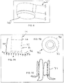
- FIG. 1A shows an exemplary embodiment of an arteriovenous graft 10 that includes multiple self-closing access ports 30, e.g., each including a circular elastic band ("CEB") 50, e.g., as shown further in FIGS. 1D and IE.
- the CEBs 50 may be preformed within the AV graft, e.g., to provide two ports for standard arterial and venous access, as shown.
- a plurality of ferromagnetic elements 58 may be provided around or otherwise adjacent the CEB 50, e.g., to facilitate identifying and/or locating the access port 30, as described in the applications incorporated by reference herein.
- the graft 10 may be fabricated from well-known synthetic or biological material for vascular grafts, and the embedded port access (PA) sites may be used for access and re-access during hemodialysis using standard gauge needles, e.g., fourteen or sixteen gauge (14G-16G) needles, through the center region of the structure.
- standard gauge needles e.g., fourteen or sixteen gauge (14G-16G) needles
- the access port 30 may also be used during standard angioplasty, vascular stenting, or thrombectomy procedures to manage and maintain AV patency for dialysis.
- the structure of the CEB 50 may elastically expand radially outwardly, and, upon removal of the dialysis needle, the structure may largely return to its original size and shape without any (or significant) permanent deformation and create an immediate seal by compressing the material within the structure.
- the graft 10 may be surgically or percutaneously implanted using standard techniques of making standard incisions and/or forming suture based anastomotic junctions or unique methods of using sutureless based anastomotic junctions.
- the elastic structure may be strategically placed subcutaneously for easy access.
- the CEB subassembly (or any of the other access devices described herein) may be augmented with features or components that may facilitate identification of the access site(s) for the insertion of a dialysis needle or catheterization instruments, as described further below.
- FIG. 2 shows an exemplary embodiment of a circular elastic band or "CEB" 50 that generally includes a tubular member sized for implantation in a patient's body, e.g., either alone or incorporated into another device or system.
- FIGS. 4A and 4B show an alternative embodiment of a CEB 50' that may be used instead of CEB 50.
- the CEB 50 may be embedded or otherwise incorporated into the AV graft shown in FIGS. 1A, 1C, and 1D .
- the CEB 50 may be implanted directly into tissue, e.g., to seal a puncture or other opening through tissue.
- the CEB 50 is resiliency expandable from a contracted condition to an enlarged condition, yet biased to return towards the contracted condition.
- the CEB 50 includes a plurality of struts 52 defining a serpentine pattern around a circumference of the CEB, each strut 52 including opposing ends that are alternately connected to adjacent struts, e.g., by curved connectors or elements 54, to define a zigzag or other serpentine pattern.
- the struts 52 may contact one another or otherwise minimize the cross-section of a lumen 56 extending through the CEB 50, yet may become spaced apart from one another as the CEB 50 is expanded to the enlarged condition, thereby increasing the size of the lumen 56 extending through the CEB 50, e.g., to accommodate receiving one or more devices or other structures through the lumen 56.
- rings or bands may be provided for the eEB 50, e.g., a tubular mesh band that is expandable to provide a passage through the band to accommodate one or more instruments, yet resiliently compressible to close the passage upon removal of the instruments), as described elsewhere herein.
- each access port 30 may include a plurality of markers, e.g., ferromagnetic, echogenic, or other elements 58, e.g., surrounding or otherwise adjacent the access port 30. As shown in FIG. ID, three magnetic elements 58 are shown spaced apart and surrounding the CEB 50.
- the locator device 60 may include a similar arrangement of ferromagnetic elements 62 that may correspond to the elements 58 in the access port 50.
- the locator device 60 may include an alignment hole 64 surrounded by the elements 62, e.g., to guide a needle or other instrument (not shown) through the access port 30.
- the elements 58, 62 may guide the locator device 60 to align the hole 64 with the CEB 50, thereby facilitating a needle through the hole 64 and the CEB 50 into the graft 10.
- the locator device 60 may include an inductance meter or other sensor (not shown) to identify and/or locate the access port 30, e.g., to identify the CEB 50 or elements 58.
- the locator device 60' may include a pad 66,' e.g., an antiseptic pad thereon.
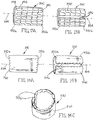
- FIGS. 10A-11C another embodiment of a self-sealing access port 130 is shown that may be provided separate from a graft, blood vessel, or other tubular structure (not shown).
- the access port 130 may be attached to a body structure or otherwise implanted within a patient's body, e.g., around or otherwise onto a tubular body structure (e.g., a native or non-native, implanted tubular structure), an organ, or tissue structure within the patient's body, as described further below.
- the access port 130 includes a flexible cuff, patch, or other port body 132 and a side port 140 including an elastic ring or CEB 150, e.g., surrounding or embedded in a plug 142.
- the port body 132 may have a first end 132a, a second end 132b, and a generally "C" shaped or other arcuate cross-section between the first and second ends 132a, 132b, thereby defining side edges 136 extending between the first and second ends 132a, 132b, e.g., substantially parallel to a central longitudinal axis 134 of the port body 132.
- the port body 132 may define a periphery between the side edges 136 that is greater than one hundred eighty degrees (180°), e.g., between about 180-350°, thereby providing a "cuff" that may be positioned around a tubular body structure, such as a tubular graft, fistula, and the like, as described further below.
- the side edges 136 may be separated to open the cuff 132, e.g., to a substantially flat or larger diameter shape that facilitates positioning the port body 132 around a tubular structure.
- the side edges 136 may be released, and the port body 132 may resiliently return towards its original shape, e.g., to secure or stabilize the access port 130 around the tubular structure.
- the port body 132 may define a periphery less than one hundred eighty degrees (180°) (not shown), e.g., between about 10-180°, thereby providing a "patch" that may be attached to a wall of a tubular structure, an organ, or other tissue structure, also as described further below.
- the port body 132 and side port 140 may be formed from flexible and/or substantially nonporous base material, e.g. silicone or other elastomeric material, and may be covered with fabric or other porous material 160, as shown in FIGS. 11A-11D , e.g., to promote tissue ingrowth after implantation and/or to integrate the components of the access port 130.
- the access port 130 may be covered with a synthetic fabric 160, such as polyester, PTFE, and the like, e.g., having a porosity or internodal distance ("IND") between about forty and one hundred fifty micrometers (40-150 ⁇ m), e.g., between about sixty and one hundred micrometers (60-100 ⁇ m).
- IND porosity or internodal distance
- the fabric 160 may have a loose weave on one surface (or alternatively may have textured, fluffed, and/or selectively cut fibers created through a variety of mechanical methods) that better enables the base material to mechanically engage with the fibers of the fabric during the forming, molding, layering, and/or assembly process, e.g., to minimize and/or eliminate any gaps between the base material and the fabric 160.
- the ring 150 may be formed from an elastic, superelastic, or shape memory material, such as a nickel-titanium alloy (“Nitinol”), that may be resiliently expanded, e.g., to accommodate receiving a needle, guidewire, catheter, introducer sheath, and the like through the side port 140, and biased to compress radially inwardly to self-seal the side port 140, similar to the CEB 50 described above.
- Niol nickel-titanium alloy
- the side port 140 may be attached to or integrally formed with the port body 132, e.g., such that the side port 140 extends transversely from an outer surface of the port body 132.
- the side port 140 may extend substantially parallel to a transverse axis 146 defining an acute angle relative to the longitudinal axis 136, e.g., between about five and ninety degrees (5-90°), or about twenty degrees (20°).
- the side port 140 may include a flexible tubular or solid cylindrical plug 142 including an elastic ring 150 surrounding and/or embedded therein, e.g., to surround and/or compress the plug 142 radially inwardly on itself. Similar to the CEB 50 shown in FIG.
- the ring 150 may include a plurality of struts 152 defining a serpentine pattern around a circumference of the ring 150, each strut 152 including opposing ends that are alternately connected to adjacent struts 152, e.g., by curved connectors or other elements 154, to define a zigzag or other serpentine pattern.
- the ring 150 may include a mesh or other interconnected strut pattern that may accommodate expansion of the ring 150 yet bias the ring 150 to return inwardly to compress the plug 142 and/or seal the side port 140.
- the plug 142 may be formed from silicone or other elastomeric material, e.g., by one or more of molding, casting, machining, spinning, and the like, having a desired relaxed diameter or oval shape, e.g., between about 0.1-0.5 inch (2.5-12.5 mm) or about 0.21-0.25 inch (5.25-6.25 mm).
- the ring 150 may be formed, for example, by laser cutting the struts 152 and connectors or elements 154 from a section of Nitinol tubing, or by cutting the struts 152 and elements 154 from a flat sheet and rolling them into a tubular shape and attaching the opposing edges.
- the ring 150 may be heat treated to provide a desired elasticity, e.g., allowing the ring 150 to be elastically expanded yet biased to a compress radially inwardly towards the original, relaxed diameter.
- the ring 150 may be biased to a diameter smaller than the plug 142, and the ring 150 may be radially expanded, positioned around the plug 142, and released, whereupon the ring 1 50 compresses radially inwardly around the plug 142.
- the ring 150 may be biased to a diameter similar to the outer diameter of the plug 142, e.g., if the diameter of the plug 142 is slightly larger or smaller than one or more instruments likely to be inserted through the side port 140.
- another layer of silicone or other material may be applied around the ring 150 and the assembly may be fused, e.g., by one or more of heating, melting, fusing, casting; and the like, and/or the plug 142 may be softened to allow the ring 150 to become embedded within the plug 142.
- the port body 132 may be formed from a tubular body of flexible base material, e.g., formed from silicone or other elastomeric material, a substantially nonporous material, a bioabsorbable material (as described elsewhere herein), and the like, before or after forming the side port 140,
- the side port 140 may be mounted in a mold or on a mandrel (not shown) such that a tubular body may be molded, spun, cast, or otherwise formed on one end of the side port 140, e.g., with the side port 140 defining the desired transverse angle 146.
- the tubular body may be split or otherwise separated along its length, e.g., generally opposite the side port 140 to provide the side edges 136 shown in FIGS. 11B and 11C .
- the port body 132 may be molded, cast, or otherwise formed in a "C" shape, e.g., if the port body 132 has a periphery substantially less than 360°.
- tubular body for the port body 132 may be formed using other methods, e.g., before or after the side port 140, and the side port 140 may be attached to the outer surface of the port body 132, e.g., before or after splitting the tubular body.
- the side port 140 and port body 132 may be formed separately, e.g., and the side port 140 may be attached to the port body 132, e.g., by one or more of bonding with adhesive, sonic welding, fusing, and the like.
- the port body 132 does not include an opening over which the side port 140 is attached or otherwise formed, although, if desired, an opening may be provided (not shown), e.g., to reduce the amount of material through which a needle or other instrument must pass through the access port 130.
- exposed surfaces may be covered with fabric 160, e.g., by one or more of stitching, bonding with adhesive, and the like, to provide the completed access port 130.
- fabric 160 e.g., by one or more of stitching, bonding with adhesive, and the like.
- the inner and outer surfaces, end surfaces, and the like of the port body 132, and the outer surfaces of the side port 140 are covered with one or more pieces of fabric 160, e.g., with separate pieces of fabric being stitched or otherwise attached together, as shown.
- the access port 130 may include one or more features to facilitate identifying and/or locating the side port 140, e.g., without direct visualization since the access port 130 may be implanted subcutaneously within a patient's body.
- the side port 140 may extend from the port body 132 with sufficient height that the side port 140 and the access port 130 may be implanted sufficiently close to the patient's skin that the side port 140 may be identified tactilely.
- the side port 140 may include one or more raised elements (not shown) that facilitate tactilely locating the side port 140 through the patient's skin.
- the side port 140 may include one or more ferromagnetic elements that may facilitate locating the side port 140 using a magnetic locator, as described elsewhere herein, echogenic elements that may facilitate locating the side port 140 using an external ultrasound device, and the like.
- the resulting access port 130 may be attached to a tubular structure, e.g., a tubular graft , fistula, blood vessel, and the like, or other tissue or body structure (not shown), e.g., before or after the tabular structure is implanted within a patient's body.
- a tubular structure e.g., a tubular graft , fistula, blood vessel, and the like, or other tissue or body structure (not shown)
- the access port 130 may be attached to the tubular structure before introduction into the patient's body, e.g., as described below with reference to FIGS. 12A and 12B .
- the target site may be accessed, e.g., using known procedures, and the access port 130 may be secured around or to the tubular structure in situ.
- the side edges 136 of the port body 132 may be opened and the access port 130 positioned at a desired location on the tubular structure. The side edges 136 may then be released such that the port body 132 wraps at least partially around the tubular structure, e.g., depending upon whether the periphery of the port body 132 is similar to or smaller than the circumference of the tubular structure.
- the port body 132 may be secured to the outer surface of the tubular structure, e.g., by one or more of stitching with sutures, bonding with adhesive, and the like.
- the inner surface of the port body 132 may include an adhesive or other material (not shown), which may bond to the tubular structure or another adhesive component applied to the wall of the tubular structure, for facilitating attaching or otherwise securing the port body 132 to the tubular structure.
- the port body 132 may include one or more features on the first and/or second ends 132a, 132b to reduce risk of the tubular structure kinking.
- spiral wire, axial tabs, or other features may extend axially or circumferentially from the first and/or second ends 132a, 132b at least partially around the periphery of the port body 132.
- Such features may be formed from metal, such as stainless steel or Nitinol, polymers, composite materials, and the like.
- spiral strands may extend beyond the port body 132 that may be wrapped at least partially around the tubular structure to reduce the risk of kinking immediately adjacent the access port 130.
- the access port 132 may be attached to any desired structure sized to receive the port body 132 thereon.
- the access port 130 may be attached to the wall of a tubular structure, or to an organ or other tissue or body structure, to which repeated access may be desired, e.g., by one or more of suturing, bonding with adhesive, and the like.
- the access port 130 may be located subcutaneously, the side port 140 may facilitate percutaneous access into the body structure to which the access port 130 is attached,
- a needle (not shown) may be inserted through the side port 140, e.g., through the ring 150 to create a passage through the plug 142, and then one or more instruments may be advanced over or through the needle, e.g., a guidewire, catheter, introducer sheath, and the like.
- the ring 150 may resiliently expand to accommodate the instrument(s) being inserted through the side port 140 into the body structure. After completing one or more diagnostic or therapeutic procedures at one or more sites accessed via the side port 140, any instruments may be removed, and the ring 150 may resiliently compress inwardly, thereby substantially closing and/or sealing the side port 140 automatically, thereby reducing or eliminating the need to provide manual compression or other measures to reduce bleeding from the access site.
- FIGS. 12A and 12B another embodiment of an access port 230 is shown that is integrally formed on a tubular structure, such as a tubular graft 210, e.g., formed from ePTFE or other material.
- the access port 230 includes a port body 232, a side port 240, and a ring 250, similar to the previous embodiments.
- the side port 240 and ring 250 may be formed similar to methods described above, e.g., such that the ring 250 surrounds or is embedded in base material of the side port 240, and/or compresses the base material radially inwardly.
- the port body 232 may be integrally formed with the side port 240 and/or formed separately and attached thereto, and then the port body 232 may be split, e.g., as described above.
- the side edges (not shown) of the port body 232 may be separated and the access port 230 positioned around the tubular graft 210.
- the port body 232 may not be split, and the access port 230 may simply be directed over one end of the graft 210 to a desired location in an enclosed tubular configuration.
- the access port 230 may then be attached to the graft 210, e.g., by one or more of bonding with adhesive, fusing, stitching with sutures, and the like.
- Fabric (not shown) may be stitched or otherwise attached over exposed surfaces of the access port 230 and/or graft 210 to provide a tubular graft 210 including a self-sealing access port 230 that may implanted with a patient's body together.
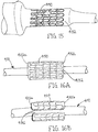
- FIGS. 13A-14C another embodiment of a self-sealing access port 330 is shown in the form of a cuff including a port body 332 of flexible base material defining a central longitudinal axis 336, a plurality of bands 350 surrounding or embedded within the port body 332, and fabric 360 covering exposed surfaces.
- the port body 332 has a generally "C" shaped cross-section including longitudinal edges 336 extending between first and second ends 332a, 332b.
- the port body 332 may be provided as a patch or other body, e.g., including a substantially planar or curved surface that may be attached to a tissue structure or other body structure, as described elsewhere herein.
- the port body 332 may be formed from one or more layers of flexible base material, e.g., silicone or other elastomeric or nonporous and/or flexible material, similar to the previous embodiments.
- the port body 332 may be formed from bioabsorbable material, e.g., polyethylene glycol, PLA, PGA, small intestinal submucosa (SIS), and the like, as described further elsewhere herein.
- the bands 350 may be formed from continuous rings or "C" shaped collars of Nitinol or other elastic or superelastic material, formed, e.g., laser cut, mechanically cut, stamped, machined, and the like, from a tube, wire, or sheet, similar to the CEB 50 and other embodiments herein. Each band 350 may extend at least partially around the periphery of the port body 332 transverse to the longitudinal axis 336.
- each band 350 may include a plurality of longitudinal struts 352 defining a serpentine pattern around a periphery of the port body 332, each strut 352 including opposing ends that are alternately connected to adjacent struts 352 by curved circumferential connectors, struts, or elements 354, e.g., to define a zigzag or other serpentine pattern.
- the longitudinal struts 352 may extend substantially parallel to the longitudinal axis 334 or, alternatively, may extend diagonally or helically relative to the longitudinal axis 334 (not shown).
- each band 350 may include a contiguous mesh or other enclosed or open pattern including struts at least partially surrounding openings (not shown) through which one or more instruments may be inserted, as described further elsewhere herein.
- the bands may include interconnected struts defining generally diamond-shaped or other enclosed openings therebetween (not shown), with the struts being separable to increase the size of the openings, e.g., to accommodate receiving one or more instruments therethrough, as described elsewhere herein.
- the struts or features of the bands may have any desired cross-section.
- the features may have generally round, elliptical, rectangular, or square cross-sections, optionally, having tapered or rounded surfaces to facilitate passing an instrument between the features.
- the features may be formed with a rectangular cross-section that may have rounded or tapered edges, e.g., by one or more of electro-polishing, machining, laser cutting, and the like.
- the features may have a thickness (extending radially relative to the central longitudinal axis 336) that is greater than their width (extending axially and/or circumferentially), which may provide increased radial support yet accommodate separation of the features "laterally,” as described further elsewhere herein.
- the bands 350 may have a cylindrical shape, e.g., including first and second ends that are spaced apart axially from one another and aligned around the periphery of the port body 332, e.g., substantially perpendicular to the longitudinal axis 334.
- the bands 350 may extend helically around the periphery of the port body 332 (not shown) and/or may have other shapes or configurations including an axial length dimension along a. length of the port body 332 and a peripheral dimension extending at least partially around the periphery of the port body 332.
- the bands 350 may be disposed immediately adjacent one another, e.g., with adjacent bands 350 in phase with one another.
- the curved connectors 354 on the first end of a first band 350 may be disposed between the curved connectors 354 on the second end of an adjacent band 350.
- adjacent bands 350 may be spaced axially apart from one another (not shown), thereby providing an unreinforced annulus of the port body 332 between adjacent bands 350, which may accommodate introducing relatively large instruments between the struts 352 and/or bands 350, as described further below.
- portions of adjacent bands may overlap one another (not shown) or a braided or other multiple layer mesh may be provided (also not shown), as long as struts or other elements of the mesh are free to move laterally and/or resiliently to accommodate one or more instruments through openings between the elements.
- adjacent bands 350 may be out of phase with one another, e.g., such that the curved connectors 354 of adjacent bands 350 are disposed adjacent one another, e.g., aligned axially or diagonally relative to one another (not shown).
- adjacent bands may define openings surrounded by pairs of struts from each adjacent hand, which may accommodate receiving relatively large instruments through the openings yet substantially closing the openings once the instrument(s) are removed.
- one or more of the curved connectors 354 on a band 350 may be coupled to one or more curved connectors 354 of an adjacent band 350.
- adjacent curved connectors 354 may be coupled directly together, or may be coupled by a flexible link (not shown), e,g., to limit movement of adjacent bands 350 relative to one another.
- the access port 330 may be formed by initially creating a tubular body of silicone or other flexible, nonporous, and or bioabsorbable base material having a desired length and/or diameter for the port body 352, e.g., by one or more of molding, casting, machining, spinning, and the like.
- the tubular body may have a length between about one and ten centimeters (1-1.0 cm), a diameter between about one and forty millimeters (1-40 mm), and a wall thickness between about 0.5 and five millimeters (0.5-5.0 mm).
- the set of bands 350 may be formed individually or simultaneously, e.g., by laser cutting from a tube, winding one or more strands in a zigzag or other circuitous pattern around a mandrel, and the like.
- a length of Nitinol wire or other material may be wound around a cylindrical mandrel (not shown) between posts to define a zigzag or other circuitous pattern to define an enclosed band (or entire set of bands) or may be wound helically along a mandrel to define a substantially continuous helical band.
- a single tube may be cut to create the set of bands 350 or a substantially continuous mesh of struts (not shown), as desired.
- the individual or set of bands 350 may have lengths between about three and one hundred twenty five millimeters (3.0-125 mm), e.g., coextensive with or less than the length of the port body 352.
- the bands 350 may be formed from a flat sheet, e.g., by one or more of laser cutting, mechanically cutting, etching, stamping, and the like, one or more sets of struts and connectors from the sheet, and then rolling the sheet.
- the longitudinal edges of the rolled sheet may remain separate, e.g., to provide "C" shaped bands, or alternatively the longitudinal edges may be attached together, e.g., by one or more of welding, soldering, fusing, bonding with adhesive, and the like, to provide an enclosed band.
- a set of bands 350 may be formed simultaneously from a tube or sheet, particularly if the bands 350 are connected together, e.g., by links or directly by adjacent connectors 354.
- the bands 350 may be heat treated and/or otherwise processed to provide a desired finish and/or mechanical properties to the bands 350.
- the bands 350 may be heat treated such that the bands 350 are biased to a desired relaxed diameter, e.g., substantially the same as or smaller than the tubular body for the port body 332, yet may be resiliency expanded and/or have one or more struts 352 and/or curved connectors 354 resiliently deformed to accommodate receiving a needle or other instrument (not shown) between adjacent struts 352, connectors 354, and/or bands 350, as described further below.
- a set of bands 350 may be placed on or embedded in the tubular body or other base material of the port body 332.
- individual bands 350 may be expanded, positioned around the tubular body, and released such that the bands 350 apply a radially inward compressive force against the tubular body.
- Such compression may be sufficient to bias the port body 332 to a desired diameter, e.g., smaller than a tubular body to which the access port 330 may be secured, for example, to reduce migration and/or otherwise secure the access port 330.
- the bands 350 may be biased to a diameter similar to the outer surface of the tubular body such that the bands 350 surround the tubular body without substantial radially inward compression.
- the bands 350 may be spaced apart from, may contact, may overlap, or may be nested between adjacent bands 350, e.g., in phase or out of phase with one another, as desired. Alternatively, if the bands 350 are connected to one another, the entire set of bands 350 may be positioned around the tubular body with or without expanding and releasing the bands.
- another layer of silicone or other flexible base material may be applied around the bands 350 to further form the port body 332, thereby embedding the bands 350 within the base material.
- an outer layer of silicone may be applied around the bands 350 and the assembly may be heated, cured, or otherwise processed to fuse, melt, or otherwise bond the material of the outer layer to the bands 350 and/or the material of the tubular body.
- the tubular body may be softened or otherwise treated to allow the bands 350 to become embedded therein, or the tubular body may be formed around the bands 350, if desired.
- the bands 350 may be secured around the tubular body, e.g., by one or more of bonding with adhesive, sonic welding, fusing, and the like.
- a plurality of bands 350 are embedded in or secured around the port body 332, e.g., two, three, four, five (as shown), or more bands 350, as desired.
- the bands 350 may be provided along substantially the entire length of the port body 332.
- the bands 350 may be provided only in a central region of the port body 332, e.g., with regions adjacent the first and second ends 332a, 332b including unsupported silicone or other base material (not shown).
- the bands 350 may provide a self-sealing or self-closing access region only along the central region with the unsupported end regions providing a transition, e.g., to reduce kinking and the like when the access port 330 is attached to a tubular structure.
- the unsupported end regions have substantially uniform properties similar to the central region or may have different properties.
- the end regions have a tapered thickness, e.g., relatively thick immediately adjacent the central region and tapering towards the ends of the port body 332, may be formed from a relatively softer durometer material, and the like,
- the access port include multiple regions embedded with or otherwise supported by bands that are separated by unsupported regions of the port body (not shown).
- a self-sealing cuff or patch may be provided that includes multiple spaced-apart self-closing access regions separated by unsupported regions.
- the port body 332 may be split or otherwise separated, e.g., by one or more of laser cutting, mechanical cutting, and the like, through the silicone material and the bands 350, to provide the side edges 3 36, as shown in FIG. 13B .
- the bands 350 may be formed as discontinuous "C" shaped collars that may be attached around or embedded within the port body 332 before or after splitting the port body 332 to create the longitudinal edges 336.
- a length of base material with embedded bands corresponding to multiple individual access ports may be formed using the methods described above, and the resulting assembly may be cut or otherwise separated into individual port bodies 332, if desired.
- the bands and port bodies may not be cut longitudinally, if a tubular access port is desired, similar to other embodiments herein.
- fabric 360 be applied over any exposed surfaces, e.g., over the outer, inner, and end surfaces of the port body 332 to provide the completed access port 330.
- one or more pieces of fabric 160 be wrapped around the port body 332 and stitched together and/or to the port body 332, e.g., similar to other embodiments herein.
- the access port 330 include one or more tactile elements, ferromagnetic elements, echogenic elements, and the like (not shown), e.g., to facilitate locating the access port 330 and or bands 350 when the access port 330 is implanted subcutaneously or otherwise within a patient's body.
- the access port 330 may be positioned around a tubular structure, e.g., a graft before or after implantation, a blood vessel, fistula, or other tubular structure (not shown) exposed or otherwise accessed within a patient's body.
- a tubular structure e.g., a graft before or after implantation, a blood vessel, fistula, or other tubular structure (not shown) exposed or otherwise accessed within a patient's body.
- the side edges 336 be separated, and the port body 332 positioned around or otherwise adjacent a tubular structure.
- the side edges 336 be released to allow the port body 332 to resiliently wrap at least partially around the tubular structure and/or the port body 332 may be attached to the tubular structure, e.g., by one or more of bonding with adhesive, suturing, fusing, and the like.
- the access port may be directed over a tubular structure from one end thereof (which be preexisting or may be created by cutting the tub
- an access port similar to access port 330 may be attached to a tubular graft or other structure before introduction and/or implantation within a patient's body.
- the access port 330 may be integrally formed into the wall of a graft, e.g., during manufacturing of the graft, if desired.
- the bands 350 or other support elements may be integrally molded or otherwise embedded within a wall of a tubular graft or other implant.
- the implant may include an integral access port that operates similar to the other embodiments herein.
- an access port 330' may be provided that includes a plurality of separate port bodies 332' that may be placed around a vessel or other tubular structure 90.
- the access port 330' includes a pair of port bodies 332' including bands or other support elements (not shown) that surround the vessel 90, e.g., in a Clamshell type configuration.
- the port bodies 332' may be attached to the vessel 90 separately or may include one or more cooperating connectors (not shown) that attach the adjacent edges of the port bodies 332' together.
- FIG. 20A an access port 330' may be provided that includes a plurality of separate port bodies 332' that may be placed around a vessel or other tubular structure 90.
- the access port 330' includes a pair of port bodies 332' including bands or other support elements (not shown) that surround the vessel 90, e.g., in a Clamshell type configuration.
- the port bodies 332' may be attached to the vessel 90 separately or may include one or more cooperating connectors (not shown) that attach
- an access port 330" is shown that includes a port body 332" having a hinged region 333.”
- the port body 332" may be opened along its length, placed around the vessel 90, and then dosed such that the side edges 336" are disposed adjacent one another.
- the side edges 336" may be spaced apart from one another, contact one another, or overlap one another, if desired, and/or may include one or more connectors (not shown) for securing the side edges 336" relative to one another, if desired.
- the access port 332,' 332" may have a diameter similar to the outer diameter of the vessel 90 or may have a slightly smaller diameter if it is desired to apply a radially compressive force to the vessel 90.
- the access ports 332,' 332" may be attached to the vessel 90, e.g., by one or more of stitching with sutures, bonding with adhesive, and the like, similar to other embodiments herein.
- the port bodies 332,' 332" may be provided as rectangular, substantially flat sheets that may simply be wrapped around a vessel 90 and secured thereto, e.g., by bonding, saturing, or clipping the port bodies 332,' 332" to the vessel 90 and/or to secure the ends of the port bodies 332,' 332" to one another.
- the resulting access ports 332,' 332" may substantially surround the entire circumference of the vessel 90, which may reduce the risk of leakage from the vessel 90, e.g., due to over-penetration, as described elsewhere herein.
- a needle (not shown) may be introduced through the patient's skin over the access port 330, and directed through the port body 332 into the lumen. If the needle encounters any of the struts 352, connectors 354, or other features of the bands 350, the encountered features may resiliently move away from the needle to create a passage through the access port 330 into the lumen.
- the struts 352, connectors 354, and/or other features of the bands 350 may resiliently separate to create a sufficiently large passage through the port body 332 to accommodate the instrument(s).
- the struts 352, connectors 354, and/or other features of the bands 350 separate "laterally,” i.e., circumferentially and/or axially within the cylindrical surface defined by the port body 332, to provide a passage through the port body 332.
- laterally refers to movement of the features of the bands 350 or other mesh substantially in a direction around the circumference and/or along the length of the port body 332 within the base material and generally not out towards the inner or outer surfaces of the port body 332 (i.e., "within the plane” of the port body 332).
- laterally refers to movement of the features of the bands substantially within the plane and generally not out of the plane towards the inner or outer surfaces.
- the material of the port body 332 may include one or more surface features to facilitate penetration of a needle or other instrument through the access port 330.
- the port body 332 may have a variable thickness, e.g., defining valleys and ridges along its outer surface (not shown), with the ridges overlying struts or other features of the bands 350 and the valleys disposed between the features of the bands 350.
- the ridges may guide the tip of the needle into the regions between the struts of the bands 350, e.g., to reduce the risk of interference between the needle and the bands 350.
- any instruments may be removed, whereupon the bands 350 may resiliently return towards their original shape, e.g., laterally inwardly towards their original configuration, thereby compressing the material of the port body 332 to close any passage created therethrough.
- the bands 350 may provide a self-sealing or, self-closing feature that automatically substantially seals any passages created through the port body 332 by a needle or other instruments.
- the features may separate to create a passage through the access port 330 that is larger than the spacing of the features in their relaxed state.
- the bands 350 may provide sufficient bias within the plane of the port body 332 to bias the port body material to resiliently close laterally inwardly around any passage created therethrough to automatically close the passage.
- the elasticity/bias of the hands 350 may reinforce and/or bias the material of the port body 332 to allow repeated access through the access port 330, while automatically closing any passages to self-seal the access port 330.
- the bias or support of the port body material between the struts of the bands 350 may also reduce the risk of the material breaking down over time due to multiple penetrations.
- One of the advantages of the access port 330 is that a needle or other instrument may be introduced at multiple locations through the port body 332, unlike the access ports 130,230. As long as the needle is inserted through a region of the access port 330 including and/or supported by one or more bands 350, the features of the bands 350 may separate or otherwise open to accommodate the needle and resiliently return towards their original configuration when all instruments are removed. Thus, in this embodiment, there may be no need for locator elements (unless provided to identify the ends of the access region), or a single access region may provide multiple access sites, rather than having to implant multiple discrete access ports.
- such bands 350 may protect the accessed tubular structure from over-penetration of needles or other instruments.
- a needle or other instrument that is inadvertently inserted into one side of the access port 330 through the entire tubular structure and out the opposite side of the access port 330 may be removed without substantial risk of bleeding or other leakage from the posterior location as well as the anterior location since the access port 330 may self-seal both openings.
- the access port 330 may be applied as a patch to the surface of any body structure, e.g., a tubular structure, such as a graft, fistula, , blood vessel, and the like, or to an organ, abdominal wall, or other tissue structure.
- a tubular structure such as a graft, fistula, , blood vessel, and the like
- the "patch" may have a variety of shapes and/or sizes depending upon the application.
- the port body 332 may have a two-dimensional shape, e.g., a rectangular, square, oval, or circular shape, with bands 350 provided along the entire surface area of the port body 332 or spaced apart inwardly from an outer perimeter of the "patch.”
- patches may be created by cutting or otherwise separating a desired shape from the tubular body described above after embedding or securing bands thereto.
- individual patches may be created by embedding or securing flat bands to patches of silicone or other base material.
- the patch may be created by laminating multiple layers of material to create a self-sealing structure that may be attached to a tissue structure.
- each layer may include elastic support elements, e.g., a mesh, struts, and the like, that support one or more layers of base material within a plane of the base material(s).
- the resulting patch may accommodate creating an opening through the base material(s) of the layers when one or more instruments are inserted through the patch, i.e., with the support demerits moving laterally within the plane of the base material(s).
- the support elements may bias the base material(s) of the respective layers laterally towards their original configuration, thereby automatically closing the opening.
- the access port 330 may be provided in a three-dimension configuration, e.g., a conical, parabolic, or other shape (not shown), having one or more bands or other structures including elastic struts embedded within or otherwise secured to a flexible base material, such as silicone or other elastomer.
- the access port 333 may be used as a patch or surgical mesh, e.g., which may be attached or otherwise secured to weakened areas of tissue or organs to provide reinforcement in addition to allowing subsequent access, if desired.
- the access port 330 may be applied as a patch for vascular repair, e.g., over a pseudo-aneurysm, or after excising a pseudo-aneurysm to reinforce the region and/or allow subsequent access.
- a surgical patch 530 that includes one or more layers of base material 532, e.g., defining a substantially flat or curved "plane," and a plurality of support elements or bands 550 embedded or otherwise attached to the base material 530,
- the base material 532 may include one or more layers of silicone or other elastomeric material that may be biased to a flat or curved planar shape or may be ''floppy," i.e., may have no particular shape and may conform substantially to any desired shape.
- the support elements include a plurality of bands 550 including features, e.g., struts 552 alternately connected by curved connectors 554, similar to other embodiments herein.
- the bands 550 may extend along a substantially linear axis across the base material 532, e.g., defining a sinusoidal or other alternating pattern, adjacent to and substantially parallel to one another.
- the features, e.g., struts 552 and connectors 554 may support the base material 532, such that the support elements 550 may be separable laterally to accommodate receiving one or more instruments (not shown) through the base material 532, yet resiliently biased to close any openings through the base material 532 created by the instrument(s), similar to other embodiments herein.
- the patch 530 may include one or more layers of base material 532 without the support elements 550 covered with fabric or other material (not shown).
- the base material 532 may be constructed to be self-supporting and resiliently biased to allow the creation of passages therethrough by a needle or other instrument (not shown), yet self-close the passage(s) upon removal of the instrument(s) to prevent substantial leakage through the patch 530.
- each layer of base material may provide axial strength in a desired axial direction, and multiple layers may be attached together with the axial directions orthogonal or otherwise intersecting one another. The direction of axial strength may be achieved by selection of the polymer or other material for the base material or by embedding strands, wires, or other axial elements within the base material (not shown).
- the surgical patch 530 may include a sewing ring or cuff 560 extending around a periphery of the base material 532, e.g., to facilitate securing the patch 530 to tissue, as described further below.
- the sewing ring 560 may include one or more layers of fabric or other material, e.g., optionally filled with foam, fabric, or other resilient, penetrable material, attached to the periphery of the base material 532, e.g., by stitching with sutures, bonding with adhesive, and the like.
- the base material 532 may also be covered with fabric or other material, e.g. the same or different material than the sewing ring 560, to enhance tissue ingrowth and/or integrate the components of the patch 530.
- the patch 530 may have a generally round shape, e.g., an elliptical, oval, or substantially circular shape.
- the patch 530 may have a square or other rectangular shape, or other geometric shape, as desired.
- the patch 530 may be provided in a "cut-to-length'* configuration, e.g., an elongate sheet or roll (not shown) of base material 532, having a predetermined width and a length sufficient to provide multiple individual patches.
- the sewing ring 560 may he omitted or may be provided along the longitudinal edges of the sheet or roll.
- the sheet or roll may include weakened regions to facilitate separating individual patches or may include unsupported regions without support elements 350 between regions with support elements 550, e.g., that may be easily cut otherwise separated to allow individual patches to be separated from the sheet or roll.
- a blood vessel 90 may include a weakened region 92 in need of repair.
- the weakened region 92 and adjacent tissue may be resected to create an opening 94, e.g., corresponding to the size and shape of the patch 530.
- the patch 530 may then be attached within or over the opening 94, e.g., by suturing the sewing ring 560 to the vessel wall surrounding the opening 94.
- the patch 530 may be attached to the wall of the vessel 90 without removing the weakened region 92, e.g., by attaching the patch 530 to the vessel 90 over the weakened region 92 or within the lumen underlying the weakened region 92, thereby supporting the weakened region 92.
- the patch 530 may be attached to a vessel wall that does not include a weakened region, e.g., as a prophylactic measure to prevent a weakened region from developing at the site of implantation.
- the patch 530 may thereafter provide a structure for supporting the vessel wall and/or provide a self-closing structure allowing multiple access to the vessel 90, similar to other embodiments herein.
- an access port patch may be attached to the apex of the left ventricle of a heart to facilitate trans-apical procedures, e.g., aortic valve replacement, and the like.
- a patch may allow one-time or repeated access through the LV apex into the left ventricle. Once the procedure is completed, any instruments introduced through the patch may be removed, and the patch may provide substantially instantaneous sealing of the LV apex.
- the access port 330 may be provided in a tubular or "C" shaped configuration, and may be introduced into a blood vessel or other body lumen.
- the access port 330 may be rolled or otherwise compressed, and loaded into a catheter, delivery sheath, and the like (not shown).
- the access port 330 may be advanced over a needle, e.g., a dialysis needle, into the interior of a graft, fistula, or other tubular structure after dialysis.
- the access port 330 may be attached to the wall of the body lumen, e.g., by one or more of stitching with sutures, bonding with adhesive, interference fit due to the radial bias of the access port 330, and the like.
- the access port 330 may provide an immediate barrier to leakage through a wall of the body lumen, e.g., to substantially seal a puncture site from the interior of the body lumen.
- the access port 330 may allow the lumen to be subsequently accessed again, as desired, with the access port 330 providing a self-sealing access region, similar to other embodiments herein.
- the access port 330 may be biased to expand to a diameter larger than the body lumen within which it is implanted.
- it may be desirable to remodel, e.g., expand, the native vein attached to an artery to create the fistula.
- the access port 330 may apply a radially outward and/or circumferential force against the surrounding wall of the vein. This bias may accelerate or enhance the natural remodeling of the vein that may occur, e.g., when the vein is exposed to arterial blood pressure.
- the entire access port 330 may include bands 350 to provide a self-dosing access region or may include one or more self-closing regions separated by unsupported regions and/or may include transition regions on the ends of the access port 330, if desired.
- any of the access devices described herein may be included in a system or kit including one or more instruments for accessing a tissue structure or graft through the access device.
- the instrument may include a needle (not shown) including a tip larger than openings through the bands 350 of the access port 330.
- the tip of the needle may be configured to facilitate passing the needle between the bands 350, e.g., to separate the struts 352, connectors, 354, and/or other features.
- the needle may include at least one of a coating, a surface treatment, and the like to facilitate passing the needle between the support elements.
- the tip may be beveled, i.e., including a beveled shape, to facilitate inserting the needle through the openings in the bands 350.
- the bands 350 may be configured to facilitate inserting the needle therethrough, e.g., by including tapered or rounded edges on the struts 352, connectors 354, and/or other features.
- the needle may include one or more features for limiting the depth of penetration of the tip through the access port 330.
- the needle may include a bumper (not shown) spaced apart a predetermined distance from the tip to prevent over-penetration of the needle through the access port 330.
- the bumper may be an annular ridge or other feature (not shown) attached around or formed around the needle at a predetermined distance from the tip.
- an access port 430 is shown that is integrally formed on a tubular structure, such as a tubular graft 410, e.g., formed from ePTFE or other material.
- the access port 430 includes a port body 432, a plurality of bands 450, and a fabric covering 460, similar to the previous embodiments.
- the port body 432 and bands 450 may be formed similar to methods described above, e.g., such that the bands 450 surround or are embedded in the material of the port body 432, and compress the material laterally and/or radially inwardly to close an opening created through the port body 432.
- the port body 432 may be formed as a tubular body, e.g., before or after attaching the bands 450, and then the port body 432 may be split, e.g., as described above. The side edges (not shown) of the port body 432 may be separated and the access port 430 positioned around the tubular graft 410. Alternatively, the port body 432 may not be split, and the access port 430 may simply be directed over one end of the graft 410 to a desired location in an enclosed tubular configuration (not shown).
- the port body may be formed from bioabsorbable material, e.g., PLA, PGA, SIS, and the like.
- the bioabsorbable material may be absorbed over time and/or replaced with connective tissue.
- the non-bioabsorbable components of the access port e.g., the bands or other resilient support elements, may remain indefinitely within the patient's body to bias the tissue structure to self-seal after one or more instruments are inserted through the bands or support elements.
- the bands or support elements may provide or enhance an elasticity of the tissue structure to accommodate access therethrough.
- the bands or support elements may be implanted without being embedded within a base material.
- the bands or support elements may be applied around a tubular structure or to a surface of an organ or other tissue structure (not shown).
- the bands or support elements may be coated or otherwise provided with agents that enhance tissue ingrowth.
- tissue may grow into and/or around the struts or other elements of the bands or support elements, thereby integrating the bands or support elements into the tissue.
- the bands or support elements may provide self-sealing access sites, similar to other embodiments herein.
- an example of an access port 630 is shown that includes a plurality of annular bands 632 that are at least partially overlapping one another, e.g., such that bands 632 define frustoconical shapes.
- Each band 632 may be formed from one or more sheets of flexible base material including a plurality of elastic bands or other support elements therein (not shown), similar to embodiments herein.
- each band 632 may include a solid panel embedded within flexible, base material (also not shown).
- the support elements may be formed from materials similar to other elements herein, e.g., Nitinol or other superelastic metal, stainless steel, cobalt chromium, or other metal.
- each band 632 includes a plurality of panels or sheets 644 attached together, e.g., to define an enclosed tubular shape, or an open configuration that may be wrapped around a tubular structure 610, such as a graft and the like.
- the sheets 644 may be partially overlapped around a periphery of each bands 632 and attached together, e.g., by bonding with adhesive, suturing, and the like.
- the sheets 644 may be provided separately and attached to the tubular structure 610 one or more at a time, e.g. by attaching a first sheet 644 and then attaching successive sheets 644 that partially overlap one or more sheets 644 already attached to the tubular structure 610.
- an access port or device 730 may be provided that includes a plurality of overlapping panels 750 embedded within flexible base or substrate material 732, which may be constructed from materials similar to any of the other embodiments herein.
- the panels 750 may include edges 752 that overlap adjacent panels, e.g., in a longitudinal direction (as shown in FIG. 25A ) and/or circumferential direction (as shown in FIG. 25B ) such that the edges 752 may be separated to provide a passage to accommodate an instrument therethrough (not shown), as described further below.
- annular band of panels 750 is provided that includes four panels whose side edges 752a partially overlap one another.
- four annular bands of panels 750 are provided along the length of the access port 730 whose end edges 752b overlap one another in a frustoconical configuration. It will be appreciated that additional or fewer panels 750 (than four shown) may be provided to define each band and/or that additional or fewer bands may be provided along the length of the access port 740, as desired,
- the access port 730 may be provided as a separate tubular body such that the access port 730 may be attached to a tubular body 710, e.g., a tubular graft or a tubular structure in situ, such as a blood vessel, fistula, or implanted graft.
- a tubular body 710 e.g., a tubular graft or a tubular structure in situ, such as a blood vessel, fistula, or implanted graft.
- the access port 730 may be provided as a cuff or patch (not shown), e.g., including side edges extending between ends of the access port 730.
- the access port 730 may have a "C" shaped cross-section or may have a substantially flat or curved shape, if desired, similar to other embodiment herein.
- the panels 750 may be provided around the entire periphery of the cuff or patch or only partially between the side edges and/or partially along the length of the cuff or patch, as desired.
- the panels 750 may be integrally formed into a wall of a tubular structure, such as a tubular graft (not shown),
- the panels 750 and/or the base material 732 may be sufficiently flexible such that the panels 750 may be separated partially from one another during use. For example, if an instrument, e.g., a needle and the like (not shown) were penetrated into the access port 730, it may encounter one of the panels 750 and may move along the panel 750 until it encounters the overlapped edges 752 of that panel 750 and an adjacent panel. Inward force of the instrument may cause the overlapped edges 752 to separate partially, e.g., by directing the panel 750 inwardly relative to the adjacent panel. Thus, the instrument may pass freely between the overlapped edges 752 and through the base material 732, e.g., into the underlying tubular body 710.
- an instrument e.g., a needle and the like (not shown) were penetrated into the access port 730, it may encounter one of the panels 750 and may move along the panel 750 until it encounters the overlapped edges 752 of that panel 750 and an adjacent panel. Inward force of the instrument may
- the panels 750 may resiliently return towards their original overlapped configuration, thereby closing and/or substantially sealing the passage created through the access port 730.
- existing pressure within the tubular body 710 may also press outwardly, thereby biasing the panels 750 to return outwardly to enhance the seal created.
- FIG. 1A an exemplary embodiment of a graft 10 is shown that includes two access ports 30, which may be any of the embodiments herein.
- the graft 10 may be formed from synthetic or biological material for vascular grafts, e.g., ePTFE, and the like, and the access ports 30 may be integrally formed or attached to the wall of the graft 10 at one or more desired locations, e.g., to allow repeated access during hemodialysis and/or other procedures.
- the graft 10 includes first and second ends 12, 14, e.g., for attaching or otherwise integrating the graft 10 with the existing vasculature of a patient.
- the first end 12 includes a tapered or beveled shape, e.g., to allow the first end 12 to be inserted into the lumen of an existing vessel and/or otherwise attached thereto, e.g., by suturing.
- the second end 14 includes a sutureless anastomotic coupler, shown in more detail in FIGS. 7A and 7B . It will be appreciated that one or both ends of the graft 10 may include any of the couplers or features described herein.
- an anastomotic flow coupler 70 may be provided on one or both ends of a graft 10, e.g., to facilitate rapid, optionally sutureless, anastomosis, cause less injury, and/or provide a smoother transition from graft to the in situ vessel 90.
- the coupler 70 may include a highly elastic structure 72 that forms a flared distal end incorporated within the substrate material of the graft 10.
- the coupler 70 may include a skeleton or other structure 72, such as a stent-like structure, e.g., including substantially straight struts alternately coupled by curved connectors, and fabricated using similar materials and/or processes as the CEB 50, described elsewhere herein.
- a skeleton or other structure 72 such as a stent-like structure, e.g., including substantially straight struts alternately coupled by curved connectors, and fabricated using similar materials and/or processes as the CEB 50, described elsewhere herein.
- the elastic structure 72 may be embedded in the material of the graft 10 or may be attached to an outer or inner surface of the graft 10, e.g., by bonding with adhesive, fusing, sonic welding, and the like. At least a portion of the coupler 70, e.g., the flared rim 74, may be covered with fabric or other material, e.g., to enhance tissue ingrowth, or alternatively, the elastic structure 72 may remain exposed.
- the flared rim 74 may have sufficient length to provide a saddle or other shape that may be attached to the vessel 90.
- the flared rim 74 may be resiliently compressible, e.g., to engage the vessel wall 90 to enhance remodeling of the vessel 90, if desired, similar to other embodiments herein.
- the flared rim 74 or the elastic structure 72 may provide a self-closing access region, similar to other embodiments herein.
- the coupler 70 may be inserted into the native vessel either surgically or percutaneously. For example, a small incision may be created in the vessel wall 90, e.g., less than the diameter of the flared end of the coupler 70, and the flared end of the coupler 70 may inserted through the incision into the lumen.
- the coupler 70 may be sheathed or otherwise constrained, e.g., within a sheath or catheter, to a diameter smaller than the incision, and inserted through the opening and into the lumen.
- the coupler 70 may then be released, e.g., by deploying the coupler 70 from the sheath such that the flared end resiliently returns to its flared shape, and the graft 10 may be pulled back until the coupler 70 is opposed firmly against the vessel wall 90.
- Intravascular pressure may further compress the flared rim of the coupler 70 against the vessel wall 90, e.g., to facilitate achieving hemostasis without requiring sutures or other connectors.
- the coupler 70 may also be attached to the vessel 90, e.g., by suturing, bonding with adhesive, and the like, if desired.
- the coupler 70 may be plastically deformable rather than self-expanding.
- the support structure 72 may be formed from plastically deformable material e.g., stainless steel or other metal, plastic, or composite materials, that may be provided initially substantially straight.
- a balloon or other expandable device (not shown), may be introduced into the coupler 70 and/or vessel 90 and expanded to deform the support structure 72 into a desired shape transitioning from the graft 10 to the vessel 90.
- FC 80 may be integrated as part of one or both ends of a graft.
- the FC 80 may provide an anastomotic and/or anti-thrombogenic : structure.
- the coupler 70 of FIGS. 7A and 7B and FC 80 of FIGS. 8A and 8B are shown substantially orthogonal to the central axis of the graft, it will be appreciated that the angle of the junction to the vessel 90 may be less than ninety degrees (90°), e.g., between about ten and fifty degrees (10-50°), which may create better flow and/or other transition from the graft to the native vessel.
- a flow coupler 170 may be provided on one (or each) end 114 of a graft 1 10 (which may or may not include access port(s) described elsewhere herein, not shown).
- the coupler 170 may include a flexible tubular material 172 having an elastic structure 180 embedded or otherwise attached thereto.
- the tubular material 172 may include fabric or other material that promotes tissue ingrowth, e.g., polyester, ePTFE (with IND between about 50-150 ⁇ m), and the like.
- the elastic structure 180 may include one or more bands or mesh of elastic or superelastic material, e.g., Nitinol, similar to the CEB 50 described above, which may be embedded in the tubular material 172 and/or may be attached to the inner or outer surface of the tubular material 172, e.g., by one or more of suturing, bonding with adhesives, fusing, sonic welding, and the like.
- elastic or superelastic material e.g., Nitinol
- the coupler 170 may include a collar 190, e.g., surrounding the tubular material 172 immediately adjacent to the end 114 of the graft 110 or elsewhere along the length of the coupler 170.
- the collar 190 may be shaped to be received around a portion of the outer wall of the vessel 90 or within the lumen of the vessel 90.
- the collar 190 may stabilize or otherwise secure the coupler 170 relative to the vessel 90, and, optionally, may be further secured to the vessel 90, e.g., by suturing, bonding with adhesive, and the like, if desired.
- the coupler 170 may have a substantially uniform diameter similar to the graft 110 or may taper or otherwise transition to a different diameter or cross-section, as desired, to provide a desired flow pattern from the graft 110 into the vessel 90, e.g., to reduce thrombosis and/or intimal hyperplasia.
- the coupler 170 may be sufficiently flexible to accommodate bending without substantial risk of kinking or buckling, e.g., allowing the coupler 170 to bend up to ninety degrees (90°) to transition from the graft 1 10 to the vessel 90 while providing a substantially smooth interior lumen.
- the elastic structure 180 may simply support the tubular structure 172 or may bias the tubular structure 172 to a desired diameter and/or shape.
- the elastic structure 180' may bias the tubular structure 172' to a bulbous shape, e.g., defining a relatively large diameter region between the end 114' of the graft 110' and the tip 174' of the coupler 170.
- the elastic structure 180' may bias the entire coupler 170' to a diameter larger than the diameter of the vessel 90, e.g., to remodel the vessel, 90 to a larger diameter or desired shape.
- a graft 110" may be provided that includes a How coupler 170" on one end 114" thereof that is biased to a helical or spiral shape.
- the coupler 170" may be sufficiently flexible to adopt any shape into which it is placed yet may be biased to return towards the helical shape to provide a desired flow characteristic through the coupler 170" after implantation.
Claims (14)
- Zugangsöffnung (330, 430, 530), die an einer Oberfläche im Körper des Patienten anbringbar ist, umfassend:einen Öffnungskörper, umfassend ein flexibles Basismaterial (332, 432, 532), das ein erstes Ende (332a), ein zweites Ende (332b), eine sich dazwischen erstreckende Längsachse (334) und eine Wand mit einer inneren und einer äußeren Oberfläche, die sich zwischen dem ersten und dem zweiten Ende erstrecken, definiert; eine Mehrzahl von elastischen Elementen (350, 450, 550), die in den Öffnungskörper eingebettet sind, wobei die elastischen Elemente trennbar sind, um einen Durchgang durch den Öffnungskörper zu schaffen, um ein Instrument aufzunehmen, das durch den Öffnungskörper hindurch eingeführt wird und elastisch vorgespannt ist, um den Durchgang im Wesentlichen zu verschließen; undTextilfläche (360), die etwaige freiliegenden Oberflächen des Öffnungskörpers bedeckt;wobei das Basismaterial aus elastomerem Material gebildet ist, wobei die elastischen Elemente in das Basismaterial eingebettet sind,wobei die Zugangsöffnung die Form einer Manschette (330, 430), die um oder an einer rohrförmigen oder anderen gekrümmten Körperstruktur befestigt werden kann, oder eines Flickens (530), der an einer rohrförmigen Struktur, einem Organ oder einer im Wesentlichen flachen Körperstruktur befestigt werden kann, aufweist, dadurch gekennzeichnet, dass das die Textilfläche ein oder mehrere Textilflächenstücke (360) umfasst, die um den Körper der Öffnung gewickelt und zusammen und/oder an den Körper der Öffnung genäht sind.
- Zugangsöffnung nach Anspruch 1, wobei die Textilfläche z.B. über die Außen-, Innen- und Endflächen des Öffnungskörpers aufgebracht ist.
- Zugangsöffnung nach Anspruch 1, wobei die elastischen Elemente eine Mehrzahl von Streben (352, 354, 552, 554) umfassen, die in einem relativ niedrigen Energiezustand nebeneinander angeordnet sind, wobei die Streben trennbar sind, um einen Durchgang durch den Öffnungskörper zwischen den Streben zu schaffen, um ein Instrument aufzunehmen, das durch den Öffnungskörper eingeführt wird, wodurch die Streben in einen relativ hohen Energiezustand versetzt werden, derart dass, wenn das Instrument entfernt wird, die Streben vorgespannt werden, um in den relativ niedrigen Energiezustand zurückzukehren und den Durchgang im Wesentlichen zu verschließen.
- Zugangsöffnung nach Anspruch 3, wobei sich die Streben in mindestens einen von im Wesentlichen senkrecht (354, 554) zur Längsachse, im Wesentlichen parallel (352, 552) zur Längsachse und schraubenförmig relativ zur Längsachse erstrecken.
- Zugangsöffnung nach einem der Ansprüche 1-4, wobei die Zugangsöffnung in Form einer Manschette (330, 430) vorliegt, die mit Textilfläche bedeckt ist, um eine Manschette mit einer integralen, durchlässigen, selbstverschließenden Oberfläche bereitzustellen.
- Zugangsöffnung nach einem vorhergehenden Anspruch, wobei der Öffnungskörper einen "C"-förmigen Querschnitt aufweist, der Seitenkanten (336) definiert, die sich zwischen dem ersten und zweiten Ende erstrecken.
- Zugangsöffnung nach Anspruch 6, wobei die Seitenkanten trennbar sind, um die Befestigung des Öffnungskörpers an einer Textilflächenstruktur zu erleichtern, der Öffnungskörper vorgespannt ist, dass er in Richtung des "C"-förmigen Querschnitts zurückkehrt, um die Befestigung des Öffnungskörpers an der Textilflächenstruktur zu verbessern.
- Zugangsöffnung nach Anspruch 6 oder 7, wobei sich jedes elastische Element quer zur Längsachse zwischen den Seitenkanten erstreckt.
- Zugangsöffnung nach Anspruch 8, wobei sich jedes elastische Element im Wesentlichen senkrecht zur Längsachse oder im Wesentlichen parallel zur Längsachse erstreckt.
- Zugangsöffnung nach einem vorhergehenden Anspruch, wobei die elastischen Elemente Längsstreben (352, 552), die sich im Wesentlichen parallel zur Längsachse erstrecken, und gekrümmte Verbinder (354, 554) umfassen, die abwechselnde Enden der Längsstreben verbinden, um ein Zickzackmuster zu definieren, derart dass sich das Zickzackmuster zwischen den Seitenkanten des Öffnungskörpers erstreckt.
- Zugangsöffnung nach Anspruch 10, wobei das Zickzackmuster ein allgemein sinusförmiges Muster aufweist, wobei die sinusförmigen Muster benachbarter Bänder entlang der Längsachse in Phase miteinander sind.
- Zugangsöffnung nach einem vorhergehenden Anspruch, wobei die elastischen Elemente unmittelbar nebeneinander angeordnet sind, wobei benachbarte elastische Elemente in Phase miteinander sind.
- Zugangsöffnung nach einem vorhergehenden Anspruch, die ferner einen Nähring oder eine Manschette (560) umfasst, die sich um einen Umfang des Basismaterials herum erstreckt.
- Implantierbares Transplantat, umfassend:ein längliches rohrförmiges Element (210, 410) einschließlich eines ersten und eines zweiten Endes und eines sich dazwischen erstreckenden Transplantatlumens; undeine Zugangsöffnung nach einem der Ansprüche 1-13, die um oder an einer Seitenwand des rohrförmigen Elements befestigt ist.
Applications Claiming Priority (4)
| Application Number | Priority Date | Filing Date | Title |
|---|---|---|---|
| US31218310P | 2010-03-09 | 2010-03-09 | |
| US38548310P | 2010-09-22 | 2010-09-22 | |
| EP11754040.1A EP2544623B1 (de) | 2010-03-09 | 2011-03-09 | Selbstschliessende vorrichtung |
| PCT/US2011/027796 WO2011112755A2 (en) | 2010-03-09 | 2011-03-09 | Self-closing devices and methods for making and using them |
Related Parent Applications (1)
| Application Number | Title | Priority Date | Filing Date |
|---|---|---|---|
| EP11754040.1A Division EP2544623B1 (de) | 2010-03-09 | 2011-03-09 | Selbstschliessende vorrichtung |
Publications (2)
| Publication Number | Publication Date |
|---|---|
| EP3338736A1 EP3338736A1 (de) | 2018-06-27 |
| EP3338736B1 true EP3338736B1 (de) | 2020-04-29 |
Family
ID=44564106
Family Applications (2)
| Application Number | Title | Priority Date | Filing Date |
|---|---|---|---|
| EP11754040.1A Active EP2544623B1 (de) | 2010-03-09 | 2011-03-09 | Selbstschliessende vorrichtung |
| EP18150646.0A Active EP3338736B1 (de) | 2010-03-09 | 2011-03-09 | Selbstschliessende vorrichtung |
Family Applications Before (1)
| Application Number | Title | Priority Date | Filing Date |
|---|---|---|---|
| EP11754040.1A Active EP2544623B1 (de) | 2010-03-09 | 2011-03-09 | Selbstschliessende vorrichtung |
Country Status (4)
| Country | Link |
|---|---|
| US (4) | US9427218B2 (de) |
| EP (2) | EP2544623B1 (de) |
| ES (2) | ES2793478T3 (de) |
| WO (1) | WO2011112755A2 (de) |
Families Citing this family (16)
| Publication number | Priority date | Publication date | Assignee | Title |
|---|---|---|---|---|
| WO2006062976A2 (en) * | 2004-12-07 | 2006-06-15 | Cook Incorporated | Methods for modifying vascular vessel walls |
| US11420033B2 (en) | 2013-01-23 | 2022-08-23 | C. R. Bard, Inc. | Low-profile single and dual vascular access device |
| US11464960B2 (en) | 2013-01-23 | 2022-10-11 | C. R. Bard, Inc. | Low-profile single and dual vascular access device |
| BR112015017424B1 (pt) | 2013-01-23 | 2022-01-18 | C.R. Bard, Inc | Porta de acesso de baixo perfil |
| JP6563900B2 (ja) * | 2013-04-13 | 2019-08-21 | ソリナス メディカル インコーポレイテッドSolinas Medical,Inc. | 自己閉鎖デバイス、装置、およびこれらの製造方法並びに送達方法 |
| US20150119908A1 (en) * | 2013-10-25 | 2015-04-30 | Abbott Cardiovascular Systems Inc. | Extravascular devices supporting an arteriovenous fistula |
| JP6749558B2 (ja) | 2014-05-14 | 2020-09-02 | プレジデント アンド フェローズ オブ ハーバード カレッジ | 光を伝達して反射させるためのカテーテル装置 |
| US11083603B2 (en) * | 2016-03-29 | 2021-08-10 | CARDINAL HEALTH SWITZERLAND 515 GmbH | Contracting stent with bioresorbable struts |
| EP3448311A4 (de) * | 2016-04-25 | 2020-01-01 | Solinas Medical, Inc. | Selbstversiegelnde rohrförmige transplantate, pflaster sowie verfahren zur herstellung davon und verwendung davon |
| CA3058442A1 (en) * | 2017-03-31 | 2018-10-04 | InnAVasc Medical, Inc. | Apparatus and method for cannulation of vascular access graft |
| USD870264S1 (en) | 2017-09-06 | 2019-12-17 | C. R. Bard, Inc. | Implantable apheresis port |
| WO2019204167A1 (en) * | 2018-04-17 | 2019-10-24 | Ruebeck David | Device and method for connecting tubular structures |
| GB2575093B (en) * | 2018-06-29 | 2022-08-17 | Spectrum Medical Ltd | Seal |
| US11925781B2 (en) | 2018-10-30 | 2024-03-12 | InnAVasc Medical, Inc. | Apparatus and method for cannulation of vascular access vessel |
| EP4171675A2 (de) * | 2020-06-30 | 2023-05-03 | NXT Biomedical, LLC | Nietdockplattform, okklusionsvorrichtung |
| GB2616438A (en) * | 2022-03-08 | 2023-09-13 | Newtec Vascular Products Ltd | Vascular stent |
Family Cites Families (135)
| Publication number | Priority date | Publication date | Assignee | Title |
|---|---|---|---|---|
| US3726279A (en) * | 1970-10-08 | 1973-04-10 | Carolina Medical Electronics I | Hemostatic vascular cuff |
| US3814137A (en) | 1973-01-26 | 1974-06-04 | Baxter Laboratories Inc | Injection site for flow conduits containing biological fluids |
| US6436135B1 (en) | 1974-10-24 | 2002-08-20 | David Goldfarb | Prosthetic vascular graft |
| US4428364A (en) | 1979-04-11 | 1984-01-31 | Dow Corning Corporation | Self-sealing injection button and method of making same |
| US4564915A (en) | 1980-04-11 | 1986-01-14 | Ampex Corporation | YIQ Computer graphics system |
| US4619641A (en) | 1984-11-13 | 1986-10-28 | Mount Sinai School Of Medicine Of The City University Of New York | Coaxial double lumen anteriovenous grafts |
| US4645495A (en) | 1985-06-26 | 1987-02-24 | Vaillancourt Vincent L | Vascular access implant needle patch |
| US4816339A (en) | 1987-04-28 | 1989-03-28 | Baxter International Inc. | Multi-layered poly(tetrafluoroethylene)/elastomer materials useful for in vivo implantation |
| US5007926A (en) * | 1989-02-24 | 1991-04-16 | The Trustees Of The University Of Pennsylvania | Expandable transluminally implantable tubular prosthesis |
| US5100422A (en) | 1989-05-26 | 1992-03-31 | Impra, Inc. | Blood vessel patch |
| US5866217A (en) | 1991-11-04 | 1999-02-02 | Possis Medical, Inc. | Silicone composite vascular graft |
| FR2688401B1 (fr) | 1992-03-12 | 1998-02-27 | Thierry Richard | Endoprothese expansible pour organe tubulaire humain ou animal, et outil de mise en place. |
| US5647855A (en) | 1992-05-06 | 1997-07-15 | Trooskin; Stanley Z. | Self-healing diaphragm in a subcutaneous infusion port |
| US5383926A (en) * | 1992-11-23 | 1995-01-24 | Children's Medical Center Corporation | Re-expandable endoprosthesis |
| US5562617A (en) | 1994-01-18 | 1996-10-08 | Finch, Jr.; Charles D. | Implantable vascular device |
| US5653743A (en) * | 1994-09-09 | 1997-08-05 | Martin; Eric C. | Hypogastric artery bifurcation graft and method of implantation |
| JP2911763B2 (ja) * | 1994-10-27 | 1999-06-23 | 三桜子 布川 | 人工血管 |
| US5591226A (en) * | 1995-01-23 | 1997-01-07 | Schneider (Usa) Inc. | Percutaneous stent-graft and method for delivery thereof |
| US5800512A (en) | 1996-01-22 | 1998-09-01 | Meadox Medicals, Inc. | PTFE vascular graft |
| US5928279A (en) | 1996-07-03 | 1999-07-27 | Baxter International Inc. | Stented, radially expandable, tubular PTFE grafts |
| EP1011524A4 (de) * | 1996-09-20 | 2001-04-25 | Medical Inc Converge | Radial ausweitbare prothesen sowie systeme zu ihrer entfaltung |
| US5906596A (en) | 1996-11-26 | 1999-05-25 | Std Manufacturing | Percutaneous access device |
| US6007516A (en) | 1997-01-21 | 1999-12-28 | Vasca, Inc. | Valve port and method for vascular access |
| US6102884A (en) | 1997-02-07 | 2000-08-15 | Squitieri; Rafael | Squitieri hemodialysis and vascular access systems |
| AU744343B2 (en) * | 1997-04-11 | 2002-02-21 | Transvascular, Inc. | Methods and apparatus for transmyocardial direct coronary revascularization |
| US5824082A (en) * | 1997-07-14 | 1998-10-20 | Brown; Roderick B. | Patch for endoscopic repair of hernias |
| US5984955A (en) * | 1997-09-11 | 1999-11-16 | Wisselink; Willem | System and method for endoluminal grafting of bifurcated or branched vessels |
| EP1018944A4 (de) * | 1997-09-26 | 2001-08-22 | Cryolife Inc | Nahtlose,ein bioadhesiv verwendende anastomosetechnik sowie vorrichtung dafür |
| US5931865A (en) | 1997-11-24 | 1999-08-03 | Gore Enterprise Holdings, Inc. | Multiple-layered leak resistant tube |
| NO981277D0 (no) * | 1998-03-20 | 1998-03-20 | Erik Fosse | Metode og anordning for suturfri anastomose |
| US6544167B2 (en) | 1998-05-01 | 2003-04-08 | Correstore, Inc. | Ventricular restoration patch |
| US6261257B1 (en) | 1998-05-26 | 2001-07-17 | Renan P. Uflacker | Dialysis graft system with self-sealing access ports |
| US5944688A (en) | 1998-07-20 | 1999-08-31 | Lois; William A | Implantable hemodialysis access port assembly |
| DE60027999T2 (de) | 1999-01-22 | 2007-04-26 | Gore Enterprise Holdings, Inc., Newark | Ummantelte endoprothese |
| US7892246B2 (en) * | 1999-07-28 | 2011-02-22 | Bioconnect Systems, Inc. | Devices and methods for interconnecting conduits and closing openings in tissue |
| US6319279B1 (en) | 1999-10-15 | 2001-11-20 | Edwards Lifesciences Corp. | Laminated self-sealing vascular access graft |
| US20040010308A1 (en) * | 2000-01-18 | 2004-01-15 | Mindguard Ltd. | Implantable composite device and corresponding method for deflecting embolic material in blood flowing at an arterial bifurcation |
| US6312463B1 (en) * | 2000-02-01 | 2001-11-06 | Endotex Interventional Systems, Inc. | Micro-porous mesh stent with hybrid structure |
| EP1276464A4 (de) | 2000-04-26 | 2009-07-08 | Std Mfg Inc | Implantierbare zugangsvorrichtung für die hämodialyse |
| US7179268B2 (en) * | 2000-07-31 | 2007-02-20 | Sumit Roy | Device, apparatus, and prosthesis for suturless anastomosis |
| US7499742B2 (en) * | 2001-09-26 | 2009-03-03 | Cvrx, Inc. | Electrode structures and methods for their use in cardiovascular reflex control |
| DE10048246A1 (de) * | 2000-09-29 | 2002-04-11 | Bosch Gmbh Robert | Vorrichtung zur Erzeugung eines Reduktionsmittel-Luft-Gemisches |
| US6623510B2 (en) | 2000-12-07 | 2003-09-23 | Integrated Vascular Systems, Inc. | Closure device and methods for making and using them |
| US6645242B1 (en) * | 2000-12-11 | 2003-11-11 | Stephen F. Quinn | Bifurcated side-access intravascular stent graft |
| EP2314293B1 (de) * | 2001-01-16 | 2017-01-04 | Vascular Therapies, LLC | Implantierbare Vorrichtung enthaltend resorbierbares Matrixmaterial und Rapamycin zur Vorbeugung oder Behandlung von vaskuloproliferativer Erkrankungen |
| US6553167B2 (en) | 2001-06-04 | 2003-04-22 | Corning Cable Systems Llc | Fiber optic cables having ultra-low shrinking filaments and methods of making the same |
| US6949118B2 (en) * | 2002-01-16 | 2005-09-27 | Percardia, Inc. | Encased implant and methods |
| NO20023605D0 (no) * | 2002-07-29 | 2002-07-29 | Sumit Roy | Fremgangsmåte og innretning til innbyrdes forbindelse av to rörformede organer |
| KR20050084599A (ko) * | 2002-09-26 | 2005-08-26 | 안지오테크 인터내셔날 아게 | 혈관주위 랩 |
| US7261705B2 (en) | 2002-10-09 | 2007-08-28 | Circuport, Inc. | Implantable dialysis access port |
| US6726711B1 (en) * | 2002-11-01 | 2004-04-27 | Joan L. Robinson | Artificial blood vessel with transcutaneous access ports |
| US8449601B2 (en) * | 2002-11-19 | 2013-05-28 | Boston Scientific Scimed, Inc. | Medical devices |
| AU2002953440A0 (en) * | 2002-12-19 | 2003-01-09 | Unisearch Limited | A method of treating a stiffened vessel |
| US7381222B2 (en) * | 2002-12-30 | 2008-06-03 | Quiescence Medical, Inc. | Stent for maintaining patency of a body region |
| US7647931B2 (en) * | 2002-12-30 | 2010-01-19 | Quiescence Medical, Inc. | Stent for maintaining patency of a body region |
| US7452374B2 (en) | 2003-04-24 | 2008-11-18 | Maquet Cardiovascular, Llc | AV grafts with rapid post-operative self-sealing capabilities |
| US7438721B2 (en) * | 2003-04-25 | 2008-10-21 | Medtronic Vascular, Inc. | Universal modular stent graft assembly to accommodate flow to collateral branches |
| US20050131520A1 (en) * | 2003-04-28 | 2005-06-16 | Zilla Peter P. | Compliant blood vessel graft |
| US8721710B2 (en) * | 2003-08-11 | 2014-05-13 | Hdh Medical Ltd. | Anastomosis system and method |
| US7762977B2 (en) | 2003-10-08 | 2010-07-27 | Hemosphere, Inc. | Device and method for vascular access |
| US20050137614A1 (en) * | 2003-10-08 | 2005-06-23 | Porter Christopher H. | System and method for connecting implanted conduits |
| WO2005037138A2 (en) * | 2003-10-14 | 2005-04-28 | Peacock James C Iii | Aneurysm treatment system and method |
| GB0402103D0 (en) | 2004-02-02 | 2004-03-03 | Hengelmolen Rudy | Tubular graft |
| AU2005218677B2 (en) * | 2004-03-02 | 2011-11-03 | Peter William Walsh | A vessel or sac wall treatment and a cardiac assist device |
| US20060025848A1 (en) * | 2004-07-29 | 2006-02-02 | Jan Weber | Medical device having a coating layer with structural elements therein and method of making the same |
| CA2577108A1 (en) | 2004-08-31 | 2006-03-09 | C.R. Bard, Inc. | Self-sealing ptfe graft with kink resistance |
| US7255682B1 (en) | 2004-09-09 | 2007-08-14 | Bartol Jr Robert J | Spot locator device |
| US20060106406A1 (en) * | 2004-09-27 | 2006-05-18 | Judah Weinberger | Methods and devices for extravascular intervention |
| US20060069426A1 (en) * | 2004-09-27 | 2006-03-30 | Weinberger Judah Z | Methods and devices for extravascular intervention |
| DE102004052408B3 (de) | 2004-10-25 | 2005-12-15 | ADEVA - medical Gesellschaft für Entwicklung und Vertrieb von medizinischen Implantat-Artikeln mbH | Gewebekonnektor |
| US9271766B2 (en) * | 2004-10-26 | 2016-03-01 | P Tech, Llc | Devices and methods for stabilizing tissue and implants |
| US8029563B2 (en) | 2004-11-29 | 2011-10-04 | Gore Enterprise Holdings, Inc. | Implantable devices with reduced needle puncture site leakage |
| US20060253197A1 (en) * | 2005-05-09 | 2006-11-09 | Napier Bradford | Shape-memory port-access tube |
| GB0515140D0 (en) * | 2005-07-22 | 2005-08-31 | Ark Therapeutics Ltd | Therapeutic device |
| US20070038224A1 (en) * | 2005-07-28 | 2007-02-15 | Ethicon Endo-Surgery, Inc. | Electroactive polymer-based flexing access port |
| DE602006019753D1 (de) * | 2005-09-01 | 2011-03-03 | Medtronic Vascular Inc | Verfahren und gerät zur behandlung von aneurysmen der a. thoracica |
| GB0521078D0 (en) * | 2005-10-17 | 2005-11-23 | T G Eakin Ltd | Access port for a medical appliance and method |
| US20070088336A1 (en) | 2005-10-17 | 2007-04-19 | Dalton Michael J | Implantable drug delivery depot for subcutaneous delivery of fluids |
| US20070106375A1 (en) * | 2005-11-07 | 2007-05-10 | Carlos Vonderwalde | Bifurcated stent assembly |
| US8163002B2 (en) | 2005-11-14 | 2012-04-24 | Vascular Devices Llc | Self-sealing vascular graft |
| US20070167901A1 (en) | 2005-11-17 | 2007-07-19 | Herrig Judson A | Self-sealing residual compressive stress graft for dialysis |
| CN101384228A (zh) * | 2005-11-17 | 2009-03-11 | 海默斯菲尔有限公司 | 用于透析的自封式残余压缩应力移植物 |
| US20070265584A1 (en) | 2006-02-15 | 2007-11-15 | Hickman Robert O | Venous prosthesis and vascular graft with access port |
| US9155646B2 (en) * | 2006-04-27 | 2015-10-13 | Brs Holdings, Llc | Composite stent with bioremovable ceramic flakes |
| US7780590B2 (en) | 2006-05-31 | 2010-08-24 | Allergan, Inc. | Method for locating an implanted fluid access port |
| US7727143B2 (en) | 2006-05-31 | 2010-06-01 | Allergan, Inc. | Locator system for implanted access port with RFID tag |
| US20070299538A1 (en) | 2006-06-26 | 2007-12-27 | Roeber Peter J | Ease of use tissue repair patch |
| US20080009889A1 (en) | 2006-07-05 | 2008-01-10 | Pokorney James L | Conduit cuff |
| US20090234431A1 (en) * | 2006-08-22 | 2009-09-17 | The Trustees Of Columbia University In The City Of New York | Arteriovenous graft blood flow controllers and methods |
| EP2572673B1 (de) * | 2006-09-02 | 2015-08-19 | Boston Scientific Scimed, Inc. | Darmschläuche und entsprechende Einsatzsysteme und -verfahren |
| US20100070019A1 (en) * | 2006-10-29 | 2010-03-18 | Aneuwrap Ltd. | extra-vascular wrapping for treating aneurysmatic aorta and methods thereof |
| US20080114444A1 (en) * | 2006-11-09 | 2008-05-15 | Chun Ho Yu | Modular stent graft and delivery system |
| US8376978B2 (en) * | 2007-02-09 | 2013-02-19 | Baxter International Inc. | Optical access disconnection systems and methods |
| US20080243080A1 (en) | 2007-03-27 | 2008-10-02 | Chang David W | Method and apparatus for vascular access |
| US10004507B2 (en) * | 2007-06-18 | 2018-06-26 | Asfora Ip, Llc | Vascular anastomosis device and method |
| US9956067B2 (en) * | 2007-07-06 | 2018-05-01 | Claude Tihon | Partial cuff |
| US10219808B2 (en) * | 2007-07-06 | 2019-03-05 | Claude Tihon | Partial cuff |
| CA2746807A1 (en) * | 2007-12-14 | 2009-06-25 | Oregon Health & Science University | Drug delivery cuff |
| US8486131B2 (en) * | 2007-12-15 | 2013-07-16 | Endospan Ltd. | Extra-vascular wrapping for treating aneurysmatic aorta in conjunction with endovascular stent-graft and methods thereof |
| US9440058B2 (en) | 2007-12-17 | 2016-09-13 | Cook Medical Technologies, LLC | Device for enabling repeated access to a vessel |
| WO2009108164A1 (en) | 2008-02-26 | 2009-09-03 | David Chang | Method and apparatus for vascular access |
| US20110295181A1 (en) | 2008-03-05 | 2011-12-01 | Hemosphere, Inc. | Implantable and removable customizable body conduit |
| CA2716995C (en) | 2008-03-05 | 2014-11-04 | Hemosphere, Inc. | Vascular access system |
| US8206430B2 (en) * | 2008-04-21 | 2012-06-26 | Medtronic Vascular, Inc. | Endolumenal sealant delivery apparatus and methods |
| US20090287145A1 (en) * | 2008-05-15 | 2009-11-19 | Altura Interventional, Inc. | Devices and methods for treatment of abdominal aortic aneurysms |
| US8414530B2 (en) | 2008-07-25 | 2013-04-09 | Roger Alan Mason | Vascular access device |
| WO2010015001A1 (en) | 2008-08-01 | 2010-02-04 | The Methodist Hospital Research Institute | Hemodialysis grafts and methods for localizing and identifying the placement of same |
| US20100121247A1 (en) * | 2008-11-13 | 2010-05-13 | Chen Yang | Dialysis Graft with Thromboses Prevention Arrangement |
| US9055946B2 (en) * | 2008-11-26 | 2015-06-16 | Phraxis Inc. | Anastomotic connector |
| US9427302B2 (en) * | 2009-04-09 | 2016-08-30 | Medtronic Vascular, Inc. | Stent having a C-shaped body section for use in a bifurcation |
| US8845682B2 (en) * | 2009-10-13 | 2014-09-30 | E-Pacing, Inc. | Vasculature closure devices and methods |
| EP2496178A1 (de) * | 2009-11-04 | 2012-09-12 | Endospan Ltd | Behandlung eines hauptkörperlumens in der nähe eines verzweigten körperlumens |
| DE102009052349A1 (de) * | 2009-11-07 | 2011-08-04 | E.S. Bio- Tech Ltd. | Vorrichtung zur Beeinflussung des Blutdrucks |
| CN102740807B (zh) * | 2009-11-30 | 2015-11-25 | 恩多斯潘有限公司 | 用于植入到具有多个分支的血管中的多部件覆膜支架系统 |
| EP2519188A4 (de) * | 2009-12-31 | 2017-03-22 | Neograft Technologies, Inc. | Transplantatvorrichtungen und verfahren zur herstellung |
| US8702776B2 (en) * | 2010-04-26 | 2014-04-22 | Paul Heltai | Method for deploying a sleeve and tubing device for restricting and constricting aneurysms and a sleeve and tubing device and system |
| US8840665B2 (en) * | 2010-06-11 | 2014-09-23 | Liventa Bioscience, Inc. | Method of tendon repair with amnion and chorion constructs |
| WO2012018917A1 (en) * | 2010-08-03 | 2012-02-09 | World Heart Corporation | Conformal cannula device and related methods |
| CN105617474B (zh) * | 2010-11-16 | 2021-02-02 | Tva医疗公司 | 用于形成瘘管的装置和方法 |
| US9433722B2 (en) * | 2011-08-09 | 2016-09-06 | Abbott Cardiovascular Systems Inc. | Vascular shield and delivery system |
| CN103813817A (zh) | 2011-09-06 | 2014-05-21 | 海默斯菲尔有限公司 | 具有连接器的血管通路系统 |
| US9539360B2 (en) | 2011-10-07 | 2017-01-10 | W. L. Gore & Associaes, Inc. | Puncturable and resealable graft |
| US9144486B2 (en) * | 2011-10-14 | 2015-09-29 | Trivascular, Inc. | Fenestrated inflatable graft |
| US10434293B2 (en) * | 2012-04-15 | 2019-10-08 | Tva Medical, Inc. | Implantable flow connector |
| ES2620761T3 (es) * | 2012-08-01 | 2017-06-29 | Laminate Medical Technologies Ltd | Aparato para configurar una fístula arteriovenosa |
| US9283096B2 (en) * | 2012-12-18 | 2016-03-15 | Empire Technology Development Llc | Vascular reinforcement device |
| US9980836B2 (en) * | 2012-12-25 | 2018-05-29 | Avraham Shekalim | Anti-restenosis coronary stent |
| JP6563900B2 (ja) * | 2013-04-13 | 2019-08-21 | ソリナス メディカル インコーポレイテッドSolinas Medical,Inc. | 自己閉鎖デバイス、装置、およびこれらの製造方法並びに送達方法 |
| US9486301B2 (en) * | 2013-06-21 | 2016-11-08 | Coloplast A/S | Artificial urinary sphincter system having a cuff with an inflatable balloon attached to a frame |
| US20150025437A1 (en) | 2013-07-18 | 2015-01-22 | Cryolife, Inc. | Vascular access system with connector |
| WO2015023460A1 (en) * | 2013-08-13 | 2015-02-19 | Cryolife, Inc. | Systems and methods for a fluid carrying conduit of a vascular access system |
| US20150119908A1 (en) * | 2013-10-25 | 2015-04-30 | Abbott Cardiovascular Systems Inc. | Extravascular devices supporting an arteriovenous fistula |
| LT3116587T (lt) * | 2014-03-11 | 2021-03-10 | Transcutan Ab | Kraujagyslių bei peritoninės prieigos prietaisas ir hemodializės prietaisas |
| EP3283005B1 (de) * | 2015-04-16 | 2020-08-19 | Sanford Health | Gefässfilter |
| US10925710B2 (en) * | 2017-03-24 | 2021-02-23 | Merit Medical Systems, Inc. | Subcutaneous vascular assemblies for improving blood flow and related devices and methods |
-
2011
- 2011-03-09 ES ES18150646T patent/ES2793478T3/es active Active
- 2011-03-09 WO PCT/US2011/027796 patent/WO2011112755A2/en active Application Filing
- 2011-03-09 EP EP11754040.1A patent/EP2544623B1/de active Active
- 2011-03-09 EP EP18150646.0A patent/EP3338736B1/de active Active
- 2011-03-09 ES ES11754040.1T patent/ES2656939T3/es active Active
-
2012
- 2012-09-09 US US13/607,783 patent/US9427218B2/en active Active
-
2015
- 2015-07-29 US US14/813,044 patent/US9848860B2/en active Active
-
2017
- 2017-12-23 US US15/853,784 patent/US10695040B2/en active Active
-
2020
- 2020-06-29 US US16/915,890 patent/US11826029B2/en active Active
Non-Patent Citations (1)
| Title |
|---|
| None * |
Also Published As
| Publication number | Publication date |
|---|---|
| EP3338736A1 (de) | 2018-06-27 |
| EP2544623A2 (de) | 2013-01-16 |
| WO2011112755A3 (en) | 2012-03-29 |
| ES2793478T3 (es) | 2020-11-16 |
| US9427218B2 (en) | 2016-08-30 |
| US9848860B2 (en) | 2017-12-26 |
| US20180116646A1 (en) | 2018-05-03 |
| EP2544623A4 (de) | 2015-07-08 |
| EP2544623B1 (de) | 2018-01-10 |
| US20130237929A1 (en) | 2013-09-12 |
| WO2011112755A2 (en) | 2011-09-15 |
| US20200397420A1 (en) | 2020-12-24 |
| US20150327844A1 (en) | 2015-11-19 |
| ES2656939T3 (es) | 2018-03-01 |
| US11826029B2 (en) | 2023-11-28 |
| US10695040B2 (en) | 2020-06-30 |
Similar Documents
| Publication | Publication Date | Title |
|---|---|---|
| US11826029B2 (en) | Self-closing devices and methods for making and using them | |
| AU2020202927B2 (en) | Occluder and anastomosis devices | |
| US11833288B2 (en) | Anastomotic devices and methods | |
| US11553941B2 (en) | Self-closing devices and apparatus and methods for making and delivering them | |
| US20220370071A1 (en) | Occluder and Anastomosis Devices | |
| WO2002058591A2 (en) | Devices and methods for interconnecting vessels | |
| EP3600150A1 (de) | Subkutane gefässanordnungen zur verbesserung des blutflusses und zugehörige vorrichtungen und verfahren | |
| AU2019253802B2 (en) | Occluder and anastomosis devices |
Legal Events
| Date | Code | Title | Description |
|---|---|---|---|
| PUAI | Public reference made under article 153(3) epc to a published international application that has entered the european phase |
Free format text: ORIGINAL CODE: 0009012 |
|
| STAA | Information on the status of an ep patent application or granted ep patent |
Free format text: STATUS: THE APPLICATION HAS BEEN PUBLISHED |
|
| AC | Divisional application: reference to earlier application |
Ref document number: 2544623 Country of ref document: EP Kind code of ref document: P |
|
| AK | Designated contracting states |
Kind code of ref document: A1 Designated state(s): AL AT BE BG CH CY CZ DE DK EE ES FI FR GB GR HR HU IE IS IT LI LT LU LV MC MK MT NL NO PL PT RO RS SE SI SK SM TR |
|
| STAA | Information on the status of an ep patent application or granted ep patent |
Free format text: STATUS: REQUEST FOR EXAMINATION WAS MADE |
|
| 17P | Request for examination filed |
Effective date: 20190102 |
|
| RBV | Designated contracting states (corrected) |
Designated state(s): AL AT BE BG CH CY CZ DE DK EE ES FI FR GB GR HR HU IE IS IT LI LT LU LV MC MK MT NL NO PL PT RO RS SE SI SK SM TR |
|
| GRAP | Despatch of communication of intention to grant a patent |
Free format text: ORIGINAL CODE: EPIDOSNIGR1 |
|
| STAA | Information on the status of an ep patent application or granted ep patent |
Free format text: STATUS: GRANT OF PATENT IS INTENDED |
|
| RIC1 | Information provided on ipc code assigned before grant |
Ipc: A61F 2/02 20060101AFI20191021BHEP Ipc: A61L 15/42 20060101ALI20191021BHEP Ipc: A61M 39/02 20060101ALI20191021BHEP Ipc: A61F 2/04 20130101ALI20191021BHEP Ipc: A61L 27/04 20060101ALI20191021BHEP |
|
| INTG | Intention to grant announced |
Effective date: 20191111 |
|
| GRAS | Grant fee paid |
Free format text: ORIGINAL CODE: EPIDOSNIGR3 |
|
| GRAA | (expected) grant |
Free format text: ORIGINAL CODE: 0009210 |
|
| STAA | Information on the status of an ep patent application or granted ep patent |
Free format text: STATUS: THE PATENT HAS BEEN GRANTED |
|
| AC | Divisional application: reference to earlier application |
Ref document number: 2544623 Country of ref document: EP Kind code of ref document: P |
|
| AK | Designated contracting states |
Kind code of ref document: B1 Designated state(s): AL AT BE BG CH CY CZ DE DK EE ES FI FR GB GR HR HU IE IS IT LI LT LU LV MC MK MT NL NO PL PT RO RS SE SI SK SM TR |
|
| REG | Reference to a national code |
Ref country code: GB Ref legal event code: FG4D |
|
| REG | Reference to a national code |
Ref country code: CH Ref legal event code: EP |
|
| REG | Reference to a national code |
Ref country code: AT Ref legal event code: REF Ref document number: 1262196 Country of ref document: AT Kind code of ref document: T Effective date: 20200515 |
|
| REG | Reference to a national code |
Ref country code: DE Ref legal event code: R096 Ref document number: 602011066612 Country of ref document: DE |
|
| REG | Reference to a national code |
Ref country code: IE Ref legal event code: FG4D |
|
| REG | Reference to a national code |
Ref country code: SE Ref legal event code: TRGR |
|
| REG | Reference to a national code |
Ref country code: NL Ref legal event code: MP Effective date: 20200429 |
|
| REG | Reference to a national code |
Ref country code: LT Ref legal event code: MG4D |
|
| PG25 | Lapsed in a contracting state [announced via postgrant information from national office to epo] |
Ref country code: IS Free format text: LAPSE BECAUSE OF FAILURE TO SUBMIT A TRANSLATION OF THE DESCRIPTION OR TO PAY THE FEE WITHIN THE PRESCRIBED TIME-LIMIT Effective date: 20200829 Ref country code: FI Free format text: LAPSE BECAUSE OF FAILURE TO SUBMIT A TRANSLATION OF THE DESCRIPTION OR TO PAY THE FEE WITHIN THE PRESCRIBED TIME-LIMIT Effective date: 20200429 Ref country code: NO Free format text: LAPSE BECAUSE OF FAILURE TO SUBMIT A TRANSLATION OF THE DESCRIPTION OR TO PAY THE FEE WITHIN THE PRESCRIBED TIME-LIMIT Effective date: 20200729 Ref country code: PT Free format text: LAPSE BECAUSE OF FAILURE TO SUBMIT A TRANSLATION OF THE DESCRIPTION OR TO PAY THE FEE WITHIN THE PRESCRIBED TIME-LIMIT Effective date: 20200831 Ref country code: LT Free format text: LAPSE BECAUSE OF FAILURE TO SUBMIT A TRANSLATION OF THE DESCRIPTION OR TO PAY THE FEE WITHIN THE PRESCRIBED TIME-LIMIT Effective date: 20200429 Ref country code: GR Free format text: LAPSE BECAUSE OF FAILURE TO SUBMIT A TRANSLATION OF THE DESCRIPTION OR TO PAY THE FEE WITHIN THE PRESCRIBED TIME-LIMIT Effective date: 20200730 |
|
| REG | Reference to a national code |
Ref country code: AT Ref legal event code: MK05 Ref document number: 1262196 Country of ref document: AT Kind code of ref document: T Effective date: 20200429 |
|
| REG | Reference to a national code |
Ref country code: ES Ref legal event code: FG2A Ref document number: 2793478 Country of ref document: ES Kind code of ref document: T3 Effective date: 20201116 |
|
| PG25 | Lapsed in a contracting state [announced via postgrant information from national office to epo] |
Ref country code: BG Free format text: LAPSE BECAUSE OF FAILURE TO SUBMIT A TRANSLATION OF THE DESCRIPTION OR TO PAY THE FEE WITHIN THE PRESCRIBED TIME-LIMIT Effective date: 20200729 Ref country code: HR Free format text: LAPSE BECAUSE OF FAILURE TO SUBMIT A TRANSLATION OF THE DESCRIPTION OR TO PAY THE FEE WITHIN THE PRESCRIBED TIME-LIMIT Effective date: 20200429 Ref country code: LV Free format text: LAPSE BECAUSE OF FAILURE TO SUBMIT A TRANSLATION OF THE DESCRIPTION OR TO PAY THE FEE WITHIN THE PRESCRIBED TIME-LIMIT Effective date: 20200429 Ref country code: RS Free format text: LAPSE BECAUSE OF FAILURE TO SUBMIT A TRANSLATION OF THE DESCRIPTION OR TO PAY THE FEE WITHIN THE PRESCRIBED TIME-LIMIT Effective date: 20200429 |
|
| PG25 | Lapsed in a contracting state [announced via postgrant information from national office to epo] |
Ref country code: AL Free format text: LAPSE BECAUSE OF FAILURE TO SUBMIT A TRANSLATION OF THE DESCRIPTION OR TO PAY THE FEE WITHIN THE PRESCRIBED TIME-LIMIT Effective date: 20200429 Ref country code: NL Free format text: LAPSE BECAUSE OF FAILURE TO SUBMIT A TRANSLATION OF THE DESCRIPTION OR TO PAY THE FEE WITHIN THE PRESCRIBED TIME-LIMIT Effective date: 20200429 |
|
| PG25 | Lapsed in a contracting state [announced via postgrant information from national office to epo] |
Ref country code: RO Free format text: LAPSE BECAUSE OF FAILURE TO SUBMIT A TRANSLATION OF THE DESCRIPTION OR TO PAY THE FEE WITHIN THE PRESCRIBED TIME-LIMIT Effective date: 20200429 Ref country code: CZ Free format text: LAPSE BECAUSE OF FAILURE TO SUBMIT A TRANSLATION OF THE DESCRIPTION OR TO PAY THE FEE WITHIN THE PRESCRIBED TIME-LIMIT Effective date: 20200429 Ref country code: EE Free format text: LAPSE BECAUSE OF FAILURE TO SUBMIT A TRANSLATION OF THE DESCRIPTION OR TO PAY THE FEE WITHIN THE PRESCRIBED TIME-LIMIT Effective date: 20200429 Ref country code: SM Free format text: LAPSE BECAUSE OF FAILURE TO SUBMIT A TRANSLATION OF THE DESCRIPTION OR TO PAY THE FEE WITHIN THE PRESCRIBED TIME-LIMIT Effective date: 20200429 Ref country code: AT Free format text: LAPSE BECAUSE OF FAILURE TO SUBMIT A TRANSLATION OF THE DESCRIPTION OR TO PAY THE FEE WITHIN THE PRESCRIBED TIME-LIMIT Effective date: 20200429 Ref country code: DK Free format text: LAPSE BECAUSE OF FAILURE TO SUBMIT A TRANSLATION OF THE DESCRIPTION OR TO PAY THE FEE WITHIN THE PRESCRIBED TIME-LIMIT Effective date: 20200429 |
|
| REG | Reference to a national code |
Ref country code: DE Ref legal event code: R097 Ref document number: 602011066612 Country of ref document: DE |
|
| PG25 | Lapsed in a contracting state [announced via postgrant information from national office to epo] |
Ref country code: PL Free format text: LAPSE BECAUSE OF FAILURE TO SUBMIT A TRANSLATION OF THE DESCRIPTION OR TO PAY THE FEE WITHIN THE PRESCRIBED TIME-LIMIT Effective date: 20200429 Ref country code: SK Free format text: LAPSE BECAUSE OF FAILURE TO SUBMIT A TRANSLATION OF THE DESCRIPTION OR TO PAY THE FEE WITHIN THE PRESCRIBED TIME-LIMIT Effective date: 20200429 |
|
| PLBE | No opposition filed within time limit |
Free format text: ORIGINAL CODE: 0009261 |
|
| STAA | Information on the status of an ep patent application or granted ep patent |
Free format text: STATUS: NO OPPOSITION FILED WITHIN TIME LIMIT |
|
| 26N | No opposition filed |
Effective date: 20210201 |
|
| PG25 | Lapsed in a contracting state [announced via postgrant information from national office to epo] |
Ref country code: SI Free format text: LAPSE BECAUSE OF FAILURE TO SUBMIT A TRANSLATION OF THE DESCRIPTION OR TO PAY THE FEE WITHIN THE PRESCRIBED TIME-LIMIT Effective date: 20200429 |
|
| PG25 | Lapsed in a contracting state [announced via postgrant information from national office to epo] |
Ref country code: MC Free format text: LAPSE BECAUSE OF FAILURE TO SUBMIT A TRANSLATION OF THE DESCRIPTION OR TO PAY THE FEE WITHIN THE PRESCRIBED TIME-LIMIT Effective date: 20200429 |
|
| REG | Reference to a national code |
Ref country code: CH Ref legal event code: PL |
|
| REG | Reference to a national code |
Ref country code: BE Ref legal event code: MM Effective date: 20210331 |
|
| PG25 | Lapsed in a contracting state [announced via postgrant information from national office to epo] |
Ref country code: LU Free format text: LAPSE BECAUSE OF NON-PAYMENT OF DUE FEES Effective date: 20210309 Ref country code: LI Free format text: LAPSE BECAUSE OF NON-PAYMENT OF DUE FEES Effective date: 20210331 Ref country code: CH Free format text: LAPSE BECAUSE OF NON-PAYMENT OF DUE FEES Effective date: 20210331 |
|
| PG25 | Lapsed in a contracting state [announced via postgrant information from national office to epo] |
Ref country code: BE Free format text: LAPSE BECAUSE OF NON-PAYMENT OF DUE FEES Effective date: 20210331 |
|
| PGFP | Annual fee paid to national office [announced via postgrant information from national office to epo] |
Ref country code: IE Payment date: 20230314 Year of fee payment: 13 Ref country code: FR Payment date: 20230314 Year of fee payment: 13 |
|
| PG25 | Lapsed in a contracting state [announced via postgrant information from national office to epo] |
Ref country code: CY Free format text: LAPSE BECAUSE OF FAILURE TO SUBMIT A TRANSLATION OF THE DESCRIPTION OR TO PAY THE FEE WITHIN THE PRESCRIBED TIME-LIMIT Effective date: 20200429 |
|
| PGFP | Annual fee paid to national office [announced via postgrant information from national office to epo] |
Ref country code: SE Payment date: 20230314 Year of fee payment: 13 Ref country code: IT Payment date: 20230320 Year of fee payment: 13 |
|
| PG25 | Lapsed in a contracting state [announced via postgrant information from national office to epo] |
Ref country code: HU Free format text: LAPSE BECAUSE OF FAILURE TO SUBMIT A TRANSLATION OF THE DESCRIPTION OR TO PAY THE FEE WITHIN THE PRESCRIBED TIME-LIMIT; INVALID AB INITIO Effective date: 20110309 |
|
| PGFP | Annual fee paid to national office [announced via postgrant information from national office to epo] |
Ref country code: ES Payment date: 20230412 Year of fee payment: 13 |
|
| PGFP | Annual fee paid to national office [announced via postgrant information from national office to epo] |
Ref country code: IE Payment date: 20240318 Year of fee payment: 14 |
|
| PG25 | Lapsed in a contracting state [announced via postgrant information from national office to epo] |
Ref country code: MK Free format text: LAPSE BECAUSE OF FAILURE TO SUBMIT A TRANSLATION OF THE DESCRIPTION OR TO PAY THE FEE WITHIN THE PRESCRIBED TIME-LIMIT Effective date: 20200429 |
|
| PGFP | Annual fee paid to national office [announced via postgrant information from national office to epo] |
Ref country code: DE Payment date: 20240319 Year of fee payment: 14 Ref country code: GB Payment date: 20240318 Year of fee payment: 14 |