EP3338725A1 - Arrangement for holding a medical device - Google Patents
Arrangement for holding a medical device Download PDFInfo
- Publication number
- EP3338725A1 EP3338725A1 EP17208864.3A EP17208864A EP3338725A1 EP 3338725 A1 EP3338725 A1 EP 3338725A1 EP 17208864 A EP17208864 A EP 17208864A EP 3338725 A1 EP3338725 A1 EP 3338725A1
- Authority
- EP
- European Patent Office
- Prior art keywords
- fixation
- arrangement
- medical device
- fixation element
- baseplate
- Prior art date
- Legal status (The legal status is an assumption and is not a legal conclusion. Google has not performed a legal analysis and makes no representation as to the accuracy of the status listed.)
- Granted
Links
Images

Classifications
-
- A—HUMAN NECESSITIES
- A61—MEDICAL OR VETERINARY SCIENCE; HYGIENE
- A61B—DIAGNOSIS; SURGERY; IDENTIFICATION
- A61B50/00—Containers, covers, furniture or holders specially adapted for surgical or diagnostic appliances or instruments, e.g. sterile covers
- A61B50/30—Containers specially adapted for packaging, protecting, dispensing, collecting or disposing of surgical or diagnostic appliances or instruments
- A61B50/33—Trays
-
- A—HUMAN NECESSITIES
- A61—MEDICAL OR VETERINARY SCIENCE; HYGIENE
- A61B—DIAGNOSIS; SURGERY; IDENTIFICATION
- A61B50/00—Containers, covers, furniture or holders specially adapted for surgical or diagnostic appliances or instruments, e.g. sterile covers
- A61B50/20—Holders specially adapted for surgical or diagnostic appliances or instruments
-
- A—HUMAN NECESSITIES
- A61—MEDICAL OR VETERINARY SCIENCE; HYGIENE
- A61B—DIAGNOSIS; SURGERY; IDENTIFICATION
- A61B50/00—Containers, covers, furniture or holders specially adapted for surgical or diagnostic appliances or instruments, e.g. sterile covers
- A61B50/30—Containers specially adapted for packaging, protecting, dispensing, collecting or disposing of surgical or diagnostic appliances or instruments
- A61B50/34—Baskets
-
- A—HUMAN NECESSITIES
- A61—MEDICAL OR VETERINARY SCIENCE; HYGIENE
- A61L—METHODS OR APPARATUS FOR STERILISING MATERIALS OR OBJECTS IN GENERAL; DISINFECTION, STERILISATION OR DEODORISATION OF AIR; CHEMICAL ASPECTS OF BANDAGES, DRESSINGS, ABSORBENT PADS OR SURGICAL ARTICLES; MATERIALS FOR BANDAGES, DRESSINGS, ABSORBENT PADS OR SURGICAL ARTICLES
- A61L2/00—Disinfection or sterilisation of materials or objects, in general; Accessories therefor
- A61L2/26—Accessories
-
- A—HUMAN NECESSITIES
- A61—MEDICAL OR VETERINARY SCIENCE; HYGIENE
- A61L—METHODS OR APPARATUS FOR STERILISING MATERIALS OR OBJECTS IN GENERAL; DISINFECTION, STERILISATION OR DEODORISATION OF AIR; CHEMICAL ASPECTS OF BANDAGES, DRESSINGS, ABSORBENT PADS OR SURGICAL ARTICLES; MATERIALS FOR BANDAGES, DRESSINGS, ABSORBENT PADS OR SURGICAL ARTICLES
- A61L2/00—Disinfection or sterilisation of materials or objects, in general; Accessories therefor
- A61L2/02—Disinfection or sterilisation of materials or objects, in general; Accessories therefor using physical processes
- A61L2/04—Heat
- A61L2/06—Hot gas
- A61L2/07—Steam
-
- A—HUMAN NECESSITIES
- A61—MEDICAL OR VETERINARY SCIENCE; HYGIENE
- A61L—METHODS OR APPARATUS FOR STERILISING MATERIALS OR OBJECTS IN GENERAL; DISINFECTION, STERILISATION OR DEODORISATION OF AIR; CHEMICAL ASPECTS OF BANDAGES, DRESSINGS, ABSORBENT PADS OR SURGICAL ARTICLES; MATERIALS FOR BANDAGES, DRESSINGS, ABSORBENT PADS OR SURGICAL ARTICLES
- A61L2103/00—Materials or objects being the target of disinfection or sterilisation
- A61L2103/15—Laboratory, medical or dentistry appliances, e.g. catheters or sharps
-
- A—HUMAN NECESSITIES
- A61—MEDICAL OR VETERINARY SCIENCE; HYGIENE
- A61L—METHODS OR APPARATUS FOR STERILISING MATERIALS OR OBJECTS IN GENERAL; DISINFECTION, STERILISATION OR DEODORISATION OF AIR; CHEMICAL ASPECTS OF BANDAGES, DRESSINGS, ABSORBENT PADS OR SURGICAL ARTICLES; MATERIALS FOR BANDAGES, DRESSINGS, ABSORBENT PADS OR SURGICAL ARTICLES
- A61L2202/00—Aspects relating to methods or apparatus for disinfecting or sterilising materials or objects
- A61L2202/10—Apparatus features
- A61L2202/18—Aseptic storing means
- A61L2202/182—Rigid packaging means
Definitions
- the invention relates to an arrangement for holding a medical device.
- Medical devices such as medical instruments, prostheses or implants need decontamination and sterilization prior to or after medical use.
- Decontamination and sterilization of such medical devices as scalpels, drills, etc. is in the art performed in cassettes comprising a tray wherein fixations parts are provided for receiving and fixation of the devices.
- the cassettes and fixation are usually arranged for a specific use in specific medical treatments such as surgery. They hold the specific devices that are required for the specific treatment in dedicated fixation elements.
- the cassettes can be used for transport after the decontamination and sterilization into specialized containers to locations where the instruments are to be utilized, such as an operating theatre.
- cassettes supplied with a fixation for medical devices to be used for decontamination, sterilization and transport (abbreviated to cassettes) is threefold: to guarantee the functionality of medical devices by protecting from damage during the decontamination and sterilization processes and transport, optimizing the cleanability of the medical devices by fixating them as spatially as possible by applying minimal contact, and with the design of the fixation within the cassette promoting a clear overview of the medical devices and/or implants before, during and following the operation.
- the trays and fixation elements are often made from a metal such as stainless steel, which is very well resistant against chemical action of detergents used in the decontamination machinery, and which is also resistant against high temperatures in sterilization conditions.
- a metal such as stainless steel
- other materials such as plastics, i.e. polymers can be used for manufacturing the trays and fixation elements, which can for example also be manufactured from silicone.
- thermal dead spots refer to locations on the instruments which may not be decontaminated or sterilized up to standard, e.g. for sterilization to reach a temperature of 134 °C for 4 minutes.
- Thermal dead spots can be cavities within the outer surface of a device. Such cavities are usually known and may require special attention and often manual intervention in decontamination.
- Thermal dead spots however can also be locations on the outer surface of an instruments which come into contact with a fixation element and which may exhibit a reduced circulation of detergent while decontaminating and sterilization agent such as steam of hot water while sterilizing.
- the medical devices in the cassette are normally held by stainless steel fixation elements. Fixation elements in the cassettes are designed to hold the instruments loosely in order to prevent thermal dead spots.
- Thermal dead spots can occur when the instrument is held by a fixation element at a location coinciding with a non-metallic part.
- the low thermal conductivity of the non-metallic part allows the local temperature to be too low for safe sterilization.
- instruments can be held in metal fixation elements, which prevent thermal dead spots.
- fixation elements may cause scratching or abrasion of the medical instrument surface.
- Additional fixation elements can be provided with resilient material such as silicone for preventing the instruments to fall out of the cassette, especially during transport. Such fixation elements however clamp the instrument and make physical contact, thereby introduce a risk of creating a thermal dead spot.
- Transport of medical instruments in trays according to the state of the art may cause wear of the instrument surfaces.
- Metal fixation elements in contact with non-metal, i.e. made from plastics or synthetic materials or any abradable material may cause increased scratching of the instrument surfaces, thereby increasing risk of non-sterile contamination of these surfaces.
- the object is achieved in an arrangement for holding a medical device, the arrangement comprising an tray, and device fixation means.
- the device fixation means comprise a at least two first fixation elements for supporting the medical device, each first fixation elements comprising a first base attached to a baseplate of the tray, and a pair of first lateral supports connected to the first base and a cross-connection between the lateral supports for holding an end of the medical device in side stabilization between the lateral supports.
- the lateral supports of the at least two first fixation elements comprise a heat conductive sheet material.
- the first lateral supports and interconnection form a gap wherein the medical device can be inserted and rest on the interconnection. Having two first supports, the medical devices can remain stable downward and laterally in the respective gaps formed by the first lateral supports in both first fixation elements.
- the holding means further comprise at least one second fixation element for partially enclosing the medical device comprising a second base for attaching the second fixation element to the baseplate of the tray, a body of insulating material connected to the base, comprising an opening in a central region of the fixation element body, a passage in the fixation element body from a top side of the fixation element to the opening, and a pair of resilient members, attached to the passage walls near the passage entrance.
- the resilient members partially bridge the passage.
- the position of the opening can be adapted to the instrument geometry and size, such that it is aligned with the instrument and its holding position in the first fixation elements.
- the opening has a position within the body, and a width and a height, which dimensions are chosen relative to a location of the cross connection of the corresponding at least two fixation elements such that the medical device preserves a distance from the heat insulating fixation element body.
- a size of the opening in the second fixation element is chosen greater than a diameter of a cross section of the medical device, such that the second fixation element is positioned around the medical device, while preserving a distance between the body and the medical device, not touching its surface.
- an instrument placed in the first and second fixation elements obtains downward and lateral stability from the first fixation elements, and contactless upward stability from the second fixation element, whereby accidental release from the second fixation element is prevented.
- the second fixation element can be placed in proximity of the at least two first fixation elements, depending on the geometry of the medical device.
- the at least one second fixation element can for example be placed between the first fixation elements at a position relative to the medical device, being supported between the first fixation elements, where the medical device can be easily inserted in the opening of the second fixation element.
- the at least one second fixation element can also be placed near the first fixation elements where the medical device extends through the gap formed by the lateral supports. Multiple fixation second elements can be used for enhancing the holding action of these elements, depending on medical device size, geometry, and weight.
- the heat conductive sheet material of the first fixation elements prevents thermal dead spots in the lateral stabilization.
- the resilient members allow the instrument to be inserted in the second fixation element while in rest not touching the walls of the opening in the second fixation element body. Thus thermal dead spots are prevented.
- the resilient members which allow access of the instrument in the fixation element body opening provide vertical upward stability and prevent the instrument from escaping the second fixation element when the tray is shaken strongly.
- the resilient member contactlessly encloses the medical instrument, so that wear or abrasion are prevented.
- the medical instrument does not touch the second fixation element in a resting position, medical devices of all materials are protected from escaping the fixation elements for example during cleaning, sterilization and transport, while thermal dead spots are prevented, even for medical devices having non-metal parts.
- a tray having medical instruments accommodated in the tray using the fixation elements as described provides contactless support in a direction perpendicular to the tray surface, thereby obviating the use of a lid. This allows the tray to be packed lidlessly with medical instruments which can be cleaned in a cleaner or washing machine, sterilized safely with no dead spots, and subsequently transported safely to a medical treatment facility.
- the body and resilient members of the second fixation element comprises an insulating material. This helps the body and resilient members to obtain a high temperature during sterilization and allow an instrument to stay hot when accidentally touching the body and/or resilient members.
- the resilient members and the body are arranged as a one- piece part. This allows easy manufacturing of body and resilient members from the same material.
- the insulating material comprises silicone. This material is resistant against temperatures in the decontamination and sterilization environment, and provide sufficient toughness and resilience for the resilient members. Moreover, silicone prevents scratching and abrasion of medical instrument surfaces while inserting or removing the instruments from the tray.
- At least one of the first fixation elements comprises a third lateral support connected to the first base, wherein the third lateral support is disposed in an extension of an axis extending between the two first fixation elements.
- the third lateral supports can be placed relative to an extension axis between the two first fixation elements depending on the geometry of the medical device, thereby preventing the medical device from sliding out of the gap formed by the first lateral supports in such forward or backward direction.
- At least part of the baseplate of the tray is liquid permeable. This allows liquid in the tray to be drained easily when used in a medical device cleaner or washer, or in an autoclave.
- the heat conductive material comprises a metal.
- the metal preferably comprises stainless steel.
- Stainless steel can normally resist harsh chemical environments by detergents and heat during decontamination and sterilization.
- the arrangement further comprises at least one additional second fixation element. This provides more stability for instruments placed in the tray during transport.
- At least one second fixation element is disposed on the baseplate of the tray between two of the first fixation elements. This allows stable position of a medical device resting on two first fixation elements while the second fixation element prevents the medical instrument from falling out of the fixation elements when the arrangement is severely shaken.
- a cassette 100 is shown for decontaminating, sterilizing and transporting medical devices 102.
- the cassette 100 comprises a tray 101 having a baseplate 103, and fixation elements 104 for holding medical devices 102, 107.
- the tray 101 and base plate 103 can be made from a metal, for example stainless steel, however also heat resistant and detergent resistant polymers can be used.
- the base plate 103 is preferably provided with openings to allow fluids to drain from the tray 101.
- the tray 101 can be further equipped with handles 105a, 105b. maar to allow handling of the tray 101 while preventing touching of the medical devices 102, 107.
- the medical devices 102, 107 are fixed to the tray 101 using fixation elements 104 as known in the art.
- the fixation elements 104 may comprise strips of an insulating material, preferably a resilient material, more preferably silicone. Silicone is a common term for materials containing polymerized siloxanes. The strips are provided with openings in which the medical devices 104 can be inserted. The insulating resilient material of the fixation elements 104 hold the medical devices 102 and prevent them from escaping from the tray 101 when the tray 101 is transported. In the art, such fixation elements 104 may exhibit thermal dead spots when a medical device is inserted in the openings.
- FIG. 1 Further shown in fig. 1 is medical device fixation arrangement 106 according to the invention.
- the medical device fixation arrangement 106 is further elucidated.
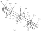
- the medical device fixation arrangement 106 in fig. 2 comprises heat conductive fixation elements 201a, 201b.
- the heat conductive fixation elements 201a, 201b have a base 204a, 204b to which lateral supports 209a, 209b are attached.
- the lateral supports 209a, 209b are interconnected by interconnection elements 210a, 210b.
- the heat conductive material of the heat conductive fixation elements 201a, 201b prevents that the contact points of where the medical device 107 rests on the interconnecting elements 210a, 210b and laterally supported by lateral supports 209a, 209b become thermal dead spots.
- Heat conducting material allows proper sterilization of the medical device 107 at the location where it is supported by the heat conductive fixation element 201a, 201b.
- Heat insulating fixation element 203 can be disposed on the base plate 103 of the tray 201 between the heat conducting fixation element 201a, 201b as shown in fig. 1 and 2 .
- the heat insulating fixation element 203 can also be disposed on the base plate 103 in proximity of these fixation elements 201a, 201b.
- the heat insulating fixation element 203 can for example also be arranged on the base plates 204a, 204b of the respective heat conduction fixation elements 201a, 201b.
- Various number and positions of the heat insulating fixation element 203 can apply relative to the heat conducting fixation elements 201a, 201b depending on size and geometry of the medical device 107.
- a further lateral support 205a, 205b can be arranged, connected to the base plate 204a, 204b of the respective heat conducting fixation elements 201a, 201b, but the additional support elements 205a, 205b can also be arranged independently from the heat conducting fixation elements 201a, 201b to the base plate 103 of the tray 101.
- the lateral support elements 205a, 205b act as end stop for the medical device 107 which would otherwise be free to slide between the lateral supports 209a, 209b without any further lateral support.
- the heat insulating fixation element 203 has a body 206 resting in a base 205 which can be arranged on a base plate 103 of the tray 101.
- the body 206 has an opening 207 to allow the medical instruments 107 to be inserted within the opening 207. Access to the opening 207 is provided via a passage 211.
- the passage 211 to the opening 207 is partially bridged by oppositely disposed resilient members 208, which are connected to the fixation element body 206.
- the resilient members208 can be placed symmetrically in the passage 111. When inserting the medical device 107, the resilient members 208 bend inwards towards opening 207 to allow the medical device 107 to pass through passage 111.
- the resilient members 208 spring back to their original position. In this position, the medical device 107 is protected from escaping from the opening 207, as it must overcome the resilience force of the resilient members 208 to be extracted from the insulation fixation element 203.
- the resilient members 208 can be made from silicone attached to the fixation element body 206.
- the fixation element body 206 can also be made from a heat insulating material such as silicone.
- Preferably the body 206 and members 208 are made as a one-piece part from silicone material.
- the body and resilient members can for example be manufactured from a single strip of silicone.
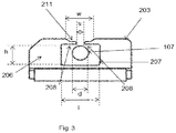
- Fig. 3 shows a side view of the heat insulating fixation element 203. It shows a cross section of the medical device 107 in an inserted state within the opening 207.
- the passage 211 to the opening 207 has a width W
- the opening between the resilient members 208 has a width S.
- width S is less than diameter d of the medical device 107, inserting and extracting the medical device 107 from opening 207 involves exerting insertion of extraction force respectively.
- the opening 207 has a position within the body 206, and width I and a height h, which dimensions are chosen such that the medical device 107 preserves a distance from the heat insulating fixation element body 206, thereby preventing thermal dead spots. Moreover, the opening 207 has a position relative to a location of the cross connection 210a, 210b of the respective at least two fixation elements 201a, 201b, to avoid contact between the medical device (107) and the body (206).
Landscapes
- Health & Medical Sciences (AREA)
- Life Sciences & Earth Sciences (AREA)
- Surgery (AREA)
- General Health & Medical Sciences (AREA)
- Animal Behavior & Ethology (AREA)
- Public Health (AREA)
- Veterinary Medicine (AREA)
- Nuclear Medicine, Radiotherapy & Molecular Imaging (AREA)
- Engineering & Computer Science (AREA)
- Biomedical Technology (AREA)
- Heart & Thoracic Surgery (AREA)
- Medical Informatics (AREA)
- Molecular Biology (AREA)
- Epidemiology (AREA)
- Apparatus For Disinfection Or Sterilisation (AREA)
- Packages (AREA)
Abstract
Description
- The invention relates to an arrangement for holding a medical device.
- Medical devices such as medical instruments, prostheses or implants need decontamination and sterilization prior to or after medical use.
- Decontamination and sterilization of such medical devices as scalpels, drills, etc. is in the art performed in cassettes comprising a tray wherein fixations parts are provided for receiving and fixation of the devices. The cassettes and fixation are usually arranged for a specific use in specific medical treatments such as surgery. They hold the specific devices that are required for the specific treatment in dedicated fixation elements. The cassettes can be used for transport after the decontamination and sterilization into specialized containers to locations where the instruments are to be utilized, such as an operating theatre.
- Generally, the intended use of the cassettes supplied with a fixation for medical devices to be used for decontamination, sterilization and transport (abbreviated to cassettes) is threefold: to guarantee the functionality of medical devices by protecting from damage during the decontamination and sterilization processes and transport, optimizing the cleanability of the medical devices by fixating them as spatially as possible by applying minimal contact, and with the design of the fixation within the cassette promoting a clear overview of the medical devices and/or implants before, during and following the operation.
- The trays and fixation elements are often made from a metal such as stainless steel, which is very well resistant against chemical action of detergents used in the decontamination machinery, and which is also resistant against high temperatures in sterilization conditions. However other materials such as plastics, i.e. polymers can be used for manufacturing the trays and fixation elements, which can for example also be manufactured from silicone.
- A problem with decontamination and sterilizing is the occurrence of so called thermal dead spots which refer to locations on the instruments which may not be decontaminated or sterilized up to standard, e.g. for sterilization to reach a temperature of 134 °C for 4 minutes. Thermal dead spots can be cavities within the outer surface of a device. Such cavities are usually known and may require special attention and often manual intervention in decontamination. Thermal dead spots however can also be locations on the outer surface of an instruments which come into contact with a fixation element and which may exhibit a reduced circulation of detergent while decontaminating and sterilization agent such as steam of hot water while sterilizing. The medical devices in the cassette are normally held by stainless steel fixation elements. Fixation elements in the cassettes are designed to hold the instruments loosely in order to prevent thermal dead spots.
- Thermal dead spots can occur when the instrument is held by a fixation element at a location coinciding with a non-metallic part. The low thermal conductivity of the non-metallic part allows the local temperature to be too low for safe sterilization. To circumvent this problem, instruments can be held in metal fixation elements, which prevent thermal dead spots. Such fixation elements however may cause scratching or abrasion of the medical instrument surface. Additional fixation elements can be provided with resilient material such as silicone for preventing the instruments to fall out of the cassette, especially during transport. Such fixation elements however clamp the instrument and make physical contact, thereby introduce a risk of creating a thermal dead spot.
- Transport of medical instruments in trays according to the state of the art may cause wear of the instrument surfaces. Metal fixation elements in contact with non-metal, i.e. made from plastics or synthetic materials or any abradable material may cause increased scratching of the instrument surfaces, thereby increasing risk of non-sterile contamination of these surfaces.
- Furthermore, while transporting medical instruments in trays as described, may cause instruments to be accidentally released from their fixation elements, thereby creating a risk that such released instruments fall out of the tray. Such accidentally released instruments may render the tray in which they were stored useless in that these instruments need to be rearranged, requiring manual intervention. Such manual intervention may compromise the sterility of the tray. Moreover the instruments integrity may be jeopardized. A known solution to prevent accidentally release of instruments is the use of a lid on top of the tray. This solution however requires manual intervention and a storage facility at the medical treatment facility such as an operating theatre or treatment room, thereby reducing ease of use or preventing cluttering of the place of treatment. Moreover use of a lid requires removal of the lid while cleaning in a washer and also likely while sterilizing.
- It is therefore an object of the invention to provide an arrangement for holding a medical device which overcomes the above stated problems and disadvantages.
- The object is achieved in an arrangement for holding a medical device, the arrangement comprising an tray, and device fixation means. The device fixation means comprise a at least two first fixation elements for supporting the medical device, each first fixation elements comprising a first base attached to a baseplate of the tray, and a pair of first lateral supports connected to the first base and a cross-connection between the lateral supports for holding an end of the medical device in side stabilization between the lateral supports. The lateral supports of the at least two first fixation elements comprise a heat conductive sheet material. The first lateral supports and interconnection form a gap wherein the medical device can be inserted and rest on the interconnection. Having two first supports, the medical devices can remain stable downward and laterally in the respective gaps formed by the first lateral supports in both first fixation elements.
- The holding means further comprise at least one second fixation element for partially enclosing the medical device comprising a second base for attaching the second fixation element to the baseplate of the tray, a body of insulating material connected to the base, comprising an opening in a central region of the fixation element body, a passage in the fixation element body from a top side of the fixation element to the opening, and a pair of resilient members, attached to the passage walls near the passage entrance. The resilient members partially bridge the passage. The position of the opening can be adapted to the instrument geometry and size, such that it is aligned with the instrument and its holding position in the first fixation elements.
- The opening has a position within the body, and a width and a height, which dimensions are chosen relative to a location of the cross connection of the corresponding at least two fixation elements such that the medical device preserves a distance from the heat insulating fixation element body.
- A size of the opening in the second fixation element is chosen greater than a diameter of a cross section of the medical device, such that the second fixation element is positioned around the medical device, while preserving a distance between the body and the medical device, not touching its surface. Thus an instrument placed in the first and second fixation elements obtains downward and lateral stability from the first fixation elements, and contactless upward stability from the second fixation element, whereby accidental release from the second fixation element is prevented. The second fixation element can be placed in proximity of the at least two first fixation elements, depending on the geometry of the medical device. The at least one second fixation element can for example be placed between the first fixation elements at a position relative to the medical device, being supported between the first fixation elements, where the medical device can be easily inserted in the opening of the second fixation element. The at least one second fixation element can also be placed near the first fixation elements where the medical device extends through the gap formed by the lateral supports. Multiple fixation second elements can be used for enhancing the holding action of these elements, depending on medical device size, geometry, and weight.
- The heat conductive sheet material of the first fixation elements prevents thermal dead spots in the lateral stabilization. The resilient members allow the instrument to be inserted in the second fixation element while in rest not touching the walls of the opening in the second fixation element body. Thus thermal dead spots are prevented. The resilient members which allow access of the instrument in the fixation element body opening provide vertical upward stability and prevent the instrument from escaping the second fixation element when the tray is shaken strongly.
- Moreover, the resilient member contactlessly encloses the medical instrument, so that wear or abrasion are prevented. The medical instrument does not touch the second fixation element in a resting position, medical devices of all materials are protected from escaping the fixation elements for example during cleaning, sterilization and transport, while thermal dead spots are prevented, even for medical devices having non-metal parts.
- Use of a lid on top of the tray to prevent instruments from release from the fixation elements and falling out of the tray during transport is circumvented. A tray having medical instruments accommodated in the tray using the fixation elements as described, provides contactless support in a direction perpendicular to the tray surface, thereby obviating the use of a lid. This allows the tray to be packed lidlessly with medical instruments which can be cleaned in a cleaner or washing machine, sterilized safely with no dead spots, and subsequently transported safely to a medical treatment facility.
- In an embodiment, the body and resilient members of the second fixation element comprises an insulating material. This helps the body and resilient members to obtain a high temperature during sterilization and allow an instrument to stay hot when accidentally touching the body and/or resilient members.
- In an embodiment, the resilient members and the body are arranged as a one- piece part. This allows easy manufacturing of body and resilient members from the same material.
- In an embodiment, the insulating material comprises silicone. This material is resistant against temperatures in the decontamination and sterilization environment, and provide sufficient toughness and resilience for the resilient members. Moreover, silicone prevents scratching and abrasion of medical instrument surfaces while inserting or removing the instruments from the tray.
- In an embodiment, at least one of the first fixation elements comprises a third lateral support connected to the first base, wherein the third lateral support is disposed in an extension of an axis extending between the two first fixation elements. The third lateral supports can be placed relative to an extension axis between the two first fixation elements depending on the geometry of the medical device, thereby preventing the medical device from sliding out of the gap formed by the first lateral supports in such forward or backward direction.
- In an embodiment, at least part of the baseplate of the tray is liquid permeable. This allows liquid in the tray to be drained easily when used in a medical device cleaner or washer, or in an autoclave.
- In an embodiment, the heat conductive material comprises a metal.
- This allows the material to spread the heat required for sterilization, thereby preventing thermal dead spots.
- In an embodiment, the metal preferably comprises stainless steel. Stainless steel can normally resist harsh chemical environments by detergents and heat during decontamination and sterilization.
- In an embodiment, the arrangement further comprises at least one additional second fixation element. This provides more stability for instruments placed in the tray during transport.
- In an embodiment, at least one second fixation element is disposed on the baseplate of the tray between two of the first fixation elements. This allows stable position of a medical device resting on two first fixation elements while the second fixation element prevents the medical instrument from falling out of the fixation elements when the arrangement is severely shaken.
-
-
Fig. 1 shows an isometric view of an arrangement for holding a medical device according to an embodiment of the invention. -
Fig. 2 shows an isometric view of fixation arrangement for the arrangement for holding a medical device offig. 1 according to an embodiment of the invention. -
Fig. 3 shows a side view of a fixation element for the arrangement for holding a medical device offig. 2 according to an embodiment of the invention. - In
fig. 1 acassette 100 is shown for decontaminating, sterilizing and transportingmedical devices 102. Thecassette 100 comprises atray 101 having abaseplate 103, andfixation elements 104 for holdingmedical devices tray 101 andbase plate 103 can be made from a metal, for example stainless steel, however also heat resistant and detergent resistant polymers can be used. Thebase plate 103 is preferably provided with openings to allow fluids to drain from thetray 101. Thetray 101 can be further equipped withhandles tray 101 while preventing touching of themedical devices medical devices tray 101 usingfixation elements 104 as known in the art. Thefixation elements 104 may comprise strips of an insulating material, preferably a resilient material, more preferably silicone. Silicone is a common term for materials containing polymerized siloxanes. The strips are provided with openings in which themedical devices 104 can be inserted. The insulating resilient material of thefixation elements 104 hold themedical devices 102 and prevent them from escaping from thetray 101 when thetray 101 is transported. In the art,such fixation elements 104 may exhibit thermal dead spots when a medical device is inserted in the openings. - Further shown in
fig. 1 is medicaldevice fixation arrangement 106 according to the invention. - In
fig. 2 the medicaldevice fixation arrangement 106 is further elucidated. The medicaldevice fixation arrangement 106 infig. 2 comprises heatconductive fixation elements conductive fixation elements base interconnection elements conductive fixation elements medical device 107 rests on the interconnectingelements lateral supports medical device 107 at the location where it is supported by the heatconductive fixation element fixation element 203 can be disposed on thebase plate 103 of the tray 201 between the heat conductingfixation element fig. 1 and2 . The heat insulatingfixation element 203 can also be disposed on thebase plate 103 in proximity of thesefixation elements fixation element 203 can for example also be arranged on thebase plates conduction fixation elements fixation element 203 can apply relative to the heat conductingfixation elements medical device 107. - In addition to the lateral supports 209a, 209b, a further
lateral support base plate fixation elements additional support elements fixation elements base plate 103 of thetray 101. As shown infig. 2 , thelateral support elements medical device 107 which would otherwise be free to slide between the lateral supports 209a, 209b without any further lateral support. - The heat insulating
fixation element 203 has abody 206 resting in a base 205 which can be arranged on abase plate 103 of thetray 101. Thebody 206 has anopening 207 to allow themedical instruments 107 to be inserted within theopening 207. Access to theopening 207 is provided via apassage 211. Thepassage 211 to theopening 207 is partially bridged by oppositely disposedresilient members 208, which are connected to thefixation element body 206. The resilient members208 can be placed symmetrically in the passage 111. When inserting themedical device 107, theresilient members 208 bend inwards towards opening 207 to allow themedical device 107 to pass through passage 111. Once themedical device 107 is introduced into theopening 207, theresilient members 208 spring back to their original position. In this position, themedical device 107 is protected from escaping from theopening 207, as it must overcome the resilience force of theresilient members 208 to be extracted from theinsulation fixation element 203. - The
resilient members 208 can be made from silicone attached to thefixation element body 206. Thefixation element body 206 can also be made from a heat insulating material such as silicone. Preferably thebody 206 andmembers 208 are made as a one-piece part from silicone material. The body and resilient members can for example be manufactured from a single strip of silicone. -
Fig. 3 shows a side view of the heat insulatingfixation element 203. It shows a cross section of themedical device 107 in an inserted state within theopening 207. As can be seen fromfig. 3 , thepassage 211 to theopening 207 has a width W, whereas the opening between theresilient members 208 has a width S. As width S is less than diameter d of themedical device 107, inserting and extracting themedical device 107 from opening 207 involves exerting insertion of extraction force respectively. - The
opening 207 has a position within thebody 206, and width I and a height h, which dimensions are chosen such that themedical device 107 preserves a distance from the heat insulatingfixation element body 206, thereby preventing thermal dead spots. Moreover, theopening 207 has a position relative to a location of thecross connection fixation elements - It will be clear to a person skilled in the art that the scope of the present invention is not limited to the examples discussed in the foregoing but that several amendments and modifications thereof are possible without deviating from the scope of the present invention as defined by the attached claims. In particular, combinations of specific features of various aspects of the invention may be made. An aspect of the invention may be further advantageously enhanced by adding a feature that was described in relation to another aspect of the invention. While the present invention has been illustrated and described in detail in the figures and the description, such illustration and description are to be considered illustrative or exemplary only, and not restrictive.
- The present invention is not limited to the disclosed embodiments. Variations to the disclosed embodiments can be understood and effected by a person skilled in the art in practicing the claimed invention, from a study of the figures, the description and the attached claims. In the claims, the word "comprising" does not exclude other steps or elements, and the indefinite article "a" or "an" does not exclude a plurality. The mere fact that certain measures are recited in mutually different dependent claims does not indicate that a combination of these measures cannot be used to advantage. Any reference numerals in the claims should not be construed as limiting the scope of the present invention.
-
- 100
- Cassette
- 101
- Tray
- 102
- Medical devices
- 103
- Tray base
- 104
- Fixation element
- 105a, 105b
- Handle
- 106
- Medical device fixation arrangement
- 107
- Medical device
- 201a, 201b
- Heat conductive fixation element
- 202
- Medical device
- 203
- Heat insulating fixation element
- 204a, 204b
- Heat conductive fixation element base
- 205a, 205b
- Lateral support element
- 206
- Fixation element body
- 207
- Opening
- 208
- Resilient member
- 209a, 209b
- Lateral support
- 210a, 210b
- Cross connection
- 211
- Passage
Claims (11)
- Arrangement (100) for holding a medical device (107), the arrangement (100) comprising:• a tray (101), comprising a baseplate (103);• medical device fixation means (106) attached to the baseplate comprising∘ at least two first fixation elements (201a, 201b) for supporting the medical device (107), each first fixation element (201a, 201b) comprising:▪ a first base (204a, 204b) that is attached to the baseplate (103); and▪ a pair of lateral supports (209a, 209b) connected to the first base (204a, 204b) for holding the medical device (107) in side stabilization between the lateral supports (209a, 209b); and▪ a cross-connection (210a, 210b) between the lateral supports (209a, 209b) for supporting the medical device (107); wherein▪ the pair of lateral supports (209a, 209b) comprise a heat conductive material;∘ at least one second fixation element (203) that is attached to the baseplate (103), for contactless enclosing a part of the medical device, the second fixation element (203) comprising:▪ a second base (205) that is attached to the baseplate (103);▪ a body (206) that is connected to the base (205), the body (206) being provided withcharacterized by• an opening (207) in a central region of the body (206);• a passage (211) in the body (206) that is arranged at a side of the body facing away from the baseplate to provide access to the opening (207);• a pair of resilient members (208) that are arranged to partially bridge the passage (211);∘ the opening (207) having position and a width (I) and a height (h) that are chosen relative to a location of the cross connections (210a, 210b) of the respective at least two first fixation elements (201a, 201b)to preserve a distance between the medical device (107) and the body (206).
- Arrangement (100) according to claim 1, wherein the body (206) and/or the resilient members (208) of the second fixation element (203) comprise an insulating material.
- Arrangement (100) according to claim 2, wherein the body (206) and the resilient members (208) are manufactured as a one-piece part.
- Arrangement (100) according to claim 2 or 3 , wherein the insulating material comprises silicone.
- Arrangement (100) according to any one of the preceding claims, wherein at least one of the first fixation elements (201a, 201b)comprises a third lateral support (205a, 205b) connected to the first base (204a, 204b), wherein the third lateral support (205a, 205b) is disposed in an extension of an axis extending between the two first fixation elements (201a, 201b).
- Arrangement (100) according to any one of the preceding claims, wherein at least part of the baseplate (103) of the tray (101) is liquid permeable.
- Arrangement (100) according to any one of the preceding claims, wherein the heat conductive material comprises a metal.
- Arrangement (100) according to claim 7, wherein the metal comprises stainless steel.
- Arrangement (100) according to any one of the preceding claims, further comprising at least one additional second fixation element (203).
- Arrangement(100) according to any one of the preceding claims, wherein the heat conductive material of the pair of lateral supports (209a, 209b) comprise heat conductive sheet material.
- Arrangement according to any one of the preceding claims, wherein at least one second fixation element (203) is disposed on the baseplate (103) between two of the first fixation elements (201a, 201b).
Applications Claiming Priority (1)
| Application Number | Priority Date | Filing Date | Title |
|---|---|---|---|
| NL2018022A NL2018022B1 (en) | 2016-12-20 | 2016-12-20 | Arrangement for holding a medical device |
Publications (2)
| Publication Number | Publication Date |
|---|---|
| EP3338725A1 true EP3338725A1 (en) | 2018-06-27 |
| EP3338725B1 EP3338725B1 (en) | 2023-01-18 |
Family
ID=57906954
Family Applications (1)
| Application Number | Title | Priority Date | Filing Date |
|---|---|---|---|
| EP17208864.3A Active EP3338725B1 (en) | 2016-12-20 | 2017-12-20 | Arrangement for holding a medical device |
Country Status (2)
| Country | Link |
|---|---|
| EP (1) | EP3338725B1 (en) |
| NL (1) | NL2018022B1 (en) |
Cited By (3)
| Publication number | Priority date | Publication date | Assignee | Title |
|---|---|---|---|---|
| CN109771039A (en) * | 2019-02-14 | 2019-05-21 | 青岛市市立医院 | A mobile operating room nursing device |
| WO2020049042A1 (en) * | 2018-09-05 | 2020-03-12 | Aesculap Ag | Packaging having a holding device for holding a medical tool |
| DE102019110385A1 (en) * | 2019-04-18 | 2020-10-22 | Karl Leibinger Medizintechnik Gmbh & Co. Kg | Implant set and method for preparing for insertion of an implant |
Citations (6)
| Publication number | Priority date | Publication date | Assignee | Title |
|---|---|---|---|---|
| US6193932B1 (en) * | 1997-12-17 | 2001-02-27 | Ethicon, Inc. | Sterilization container and instrument holder therefor |
| DE102004053355A1 (en) * | 2004-11-02 | 2006-05-11 | Klaus Gatermann | Medical objects e.g. hammer, accommodating tray, has pierced plates with holes of specific size and tightness and made up of metal, where plates are jetted by water jets of washer having sufficient cleaning effect |
| US20070205123A1 (en) * | 2005-05-24 | 2007-09-06 | Bettenhausen Todd E | Modular container for medical instruments and implants with extruded flexible bracket and rigid holders |
| FR2898277A1 (en) * | 2006-03-10 | 2007-09-14 | Hygien Or Sarl | METHOD FOR MANUFACTURING A STERILIZATION TRAY FOR MEDICAL EQUIPMENT, ESPECIALLY FOR SURGERY INSTRUMENTS |
| FR2898278A1 (en) * | 2006-03-10 | 2007-09-14 | Hygien Or Sarl | SUPPORT FOR MEDICAL EQUIPMENT, IN PARTICULAR SURGERY INSTRUMENTS, FOR STERILIZATION PLATE OF THIS MEDICAL EQUIPMENT |
| US20140083886A1 (en) * | 2012-09-21 | 2014-03-27 | Zimmer, Inc. | Modular brackets and instrumentation case |
-
2016
- 2016-12-20 NL NL2018022A patent/NL2018022B1/en not_active IP Right Cessation
-
2017
- 2017-12-20 EP EP17208864.3A patent/EP3338725B1/en active Active
Patent Citations (6)
| Publication number | Priority date | Publication date | Assignee | Title |
|---|---|---|---|---|
| US6193932B1 (en) * | 1997-12-17 | 2001-02-27 | Ethicon, Inc. | Sterilization container and instrument holder therefor |
| DE102004053355A1 (en) * | 2004-11-02 | 2006-05-11 | Klaus Gatermann | Medical objects e.g. hammer, accommodating tray, has pierced plates with holes of specific size and tightness and made up of metal, where plates are jetted by water jets of washer having sufficient cleaning effect |
| US20070205123A1 (en) * | 2005-05-24 | 2007-09-06 | Bettenhausen Todd E | Modular container for medical instruments and implants with extruded flexible bracket and rigid holders |
| FR2898277A1 (en) * | 2006-03-10 | 2007-09-14 | Hygien Or Sarl | METHOD FOR MANUFACTURING A STERILIZATION TRAY FOR MEDICAL EQUIPMENT, ESPECIALLY FOR SURGERY INSTRUMENTS |
| FR2898278A1 (en) * | 2006-03-10 | 2007-09-14 | Hygien Or Sarl | SUPPORT FOR MEDICAL EQUIPMENT, IN PARTICULAR SURGERY INSTRUMENTS, FOR STERILIZATION PLATE OF THIS MEDICAL EQUIPMENT |
| US20140083886A1 (en) * | 2012-09-21 | 2014-03-27 | Zimmer, Inc. | Modular brackets and instrumentation case |
Cited By (6)
| Publication number | Priority date | Publication date | Assignee | Title |
|---|---|---|---|---|
| WO2020049042A1 (en) * | 2018-09-05 | 2020-03-12 | Aesculap Ag | Packaging having a holding device for holding a medical tool |
| CN112638308A (en) * | 2018-09-05 | 2021-04-09 | 蛇牌股份公司 | Package with a holding device for holding a medical tool |
| US11653992B2 (en) | 2018-09-05 | 2023-05-23 | Aesculap Ag | Packaging having a holding device for holding a medical tool |
| CN109771039A (en) * | 2019-02-14 | 2019-05-21 | 青岛市市立医院 | A mobile operating room nursing device |
| CN109771039B (en) * | 2019-02-14 | 2021-05-25 | 青岛市市立医院 | A mobile operating room nursing device |
| DE102019110385A1 (en) * | 2019-04-18 | 2020-10-22 | Karl Leibinger Medizintechnik Gmbh & Co. Kg | Implant set and method for preparing for insertion of an implant |
Also Published As
| Publication number | Publication date |
|---|---|
| NL2018022B1 (en) | 2018-06-29 |
| EP3338725B1 (en) | 2023-01-18 |
Similar Documents
| Publication | Publication Date | Title |
|---|---|---|
| EP3338725B1 (en) | Arrangement for holding a medical device | |
| CN104837510B (en) | Container for the washing of article, sterilization, transport and sterile storage | |
| US6884392B2 (en) | Apparatus and method for steam reprocessing flexible endoscopes | |
| JP7528165B2 (en) | How to dry medical instruments | |
| WO1996022113A1 (en) | Sterilization and storage container tray for surgical instruments | |
| US20190231468A1 (en) | Storage assembly for a medical device | |
| KR102679922B1 (en) | probe cover | |
| JP6348604B2 (en) | Devices and methods for cleaning, disinfecting and / or sterilizing | |
| WO2011003069A2 (en) | System and method for providing a metal sterilization tray | |
| EP3675915B1 (en) | Systems and methods for instrument disinfection and anti-microbial coating | |
| CN113645914A (en) | Pipe rack equipment | |
| US20070134142A1 (en) | Medical instrument retainer assembly and method of making the retainer | |
| US3900109A (en) | Elongated surgical instrument holder | |
| US20130074450A1 (en) | Apparatus and method for securing medical instruments | |
| US12414747B2 (en) | Protective cover for C-arm flat-plate detector | |
| Brown et al. | Use of containment pans and lids for autoclaving caustic solutions | |
| Brinker et al. | Behind-the-Scenes Infection Prevention: Focusing on Clinical Surfaces and Instrument Processing. | |
| Annapurna et al. | Resurgence of plasma sterilization: A review | |
| US3533670A (en) | Sterilized tray holder rack | |
| US11351351B2 (en) | Device for sanitizing injection ports and methods of use | |
| KR102868663B1 (en) | Tray for preventing needle stick injury | |
| US20240407879A1 (en) | Fixation element, reprocessing tray, and method of reprocessing a medical device | |
| US20240050182A1 (en) | Protective casing for a thin-film lead paddle | |
| KR102515978B1 (en) | Tray for medical instruments | |
| GB2501102A (en) | Drawer assembly for holding medical items during bio-decontamination |
Legal Events
| Date | Code | Title | Description |
|---|---|---|---|
| PUAI | Public reference made under article 153(3) epc to a published international application that has entered the european phase |
Free format text: ORIGINAL CODE: 0009012 |
|
| STAA | Information on the status of an ep patent application or granted ep patent |
Free format text: STATUS: THE APPLICATION HAS BEEN PUBLISHED |
|
| AK | Designated contracting states |
Kind code of ref document: A1 Designated state(s): AL AT BE BG CH CY CZ DE DK EE ES FI FR GB GR HR HU IE IS IT LI LT LU LV MC MK MT NL NO PL PT RO RS SE SI SK SM TR |
|
| AX | Request for extension of the european patent |
Extension state: BA ME |
|
| STAA | Information on the status of an ep patent application or granted ep patent |
Free format text: STATUS: REQUEST FOR EXAMINATION WAS MADE |
|
| 17P | Request for examination filed |
Effective date: 20181129 |
|
| RBV | Designated contracting states (corrected) |
Designated state(s): AL AT BE BG CH CY CZ DE DK EE ES FI FR GB GR HR HU IE IS IT LI LT LU LV MC MK MT NL NO PL PT RO RS SE SI SK SM TR |
|
| REG | Reference to a national code |
Ref country code: DE Ref legal event code: R079 Ref document number: 602017065548 Country of ref document: DE Free format text: PREVIOUS MAIN CLASS: A61B0050200000 Ipc: A61L0002070000 |
|
| STAA | Information on the status of an ep patent application or granted ep patent |
Free format text: STATUS: EXAMINATION IS IN PROGRESS |
|
| RIC1 | Information provided on ipc code assigned before grant |
Ipc: A61L 2/07 20060101AFI20190311BHEP Ipc: A61L 2/26 20060101ALI20190311BHEP Ipc: A61B 50/34 20160101ALI20190311BHEP Ipc: A61B 50/33 20160101ALI20190311BHEP Ipc: A61B 50/20 20160101ALI20190311BHEP |
|
| 17Q | First examination report despatched |
Effective date: 20190412 |
|
| GRAP | Despatch of communication of intention to grant a patent |
Free format text: ORIGINAL CODE: EPIDOSNIGR1 |
|
| STAA | Information on the status of an ep patent application or granted ep patent |
Free format text: STATUS: GRANT OF PATENT IS INTENDED |
|
| INTG | Intention to grant announced |
Effective date: 20220826 |
|
| GRAS | Grant fee paid |
Free format text: ORIGINAL CODE: EPIDOSNIGR3 |
|
| GRAA | (expected) grant |
Free format text: ORIGINAL CODE: 0009210 |
|
| STAA | Information on the status of an ep patent application or granted ep patent |
Free format text: STATUS: THE PATENT HAS BEEN GRANTED |
|
| AK | Designated contracting states |
Kind code of ref document: B1 Designated state(s): AL AT BE BG CH CY CZ DE DK EE ES FI FR GB GR HR HU IE IS IT LI LT LU LV MC MK MT NL NO PL PT RO RS SE SI SK SM TR |
|
| REG | Reference to a national code |
Ref country code: GB Ref legal event code: FG4D |
|
| REG | Reference to a national code |
Ref country code: DE Ref legal event code: R096 Ref document number: 602017065548 Country of ref document: DE |
|
| REG | Reference to a national code |
Ref country code: CH Ref legal event code: EP |
|
| REG | Reference to a national code |
Ref country code: AT Ref legal event code: REF Ref document number: 1544321 Country of ref document: AT Kind code of ref document: T Effective date: 20230215 Ref country code: IE Ref legal event code: FG4D |
|
| REG | Reference to a national code |
Ref country code: NL Ref legal event code: FP |
|
| REG | Reference to a national code |
Ref country code: LT Ref legal event code: MG9D |
|
| REG | Reference to a national code |
Ref country code: AT Ref legal event code: MK05 Ref document number: 1544321 Country of ref document: AT Kind code of ref document: T Effective date: 20230118 |
|
| PG25 | Lapsed in a contracting state [announced via postgrant information from national office to epo] |
Ref country code: RS Free format text: LAPSE BECAUSE OF FAILURE TO SUBMIT A TRANSLATION OF THE DESCRIPTION OR TO PAY THE FEE WITHIN THE PRESCRIBED TIME-LIMIT Effective date: 20230118 Ref country code: PT Free format text: LAPSE BECAUSE OF FAILURE TO SUBMIT A TRANSLATION OF THE DESCRIPTION OR TO PAY THE FEE WITHIN THE PRESCRIBED TIME-LIMIT Effective date: 20230518 Ref country code: NO Free format text: LAPSE BECAUSE OF FAILURE TO SUBMIT A TRANSLATION OF THE DESCRIPTION OR TO PAY THE FEE WITHIN THE PRESCRIBED TIME-LIMIT Effective date: 20230418 Ref country code: LV Free format text: LAPSE BECAUSE OF FAILURE TO SUBMIT A TRANSLATION OF THE DESCRIPTION OR TO PAY THE FEE WITHIN THE PRESCRIBED TIME-LIMIT Effective date: 20230118 Ref country code: LT Free format text: LAPSE BECAUSE OF FAILURE TO SUBMIT A TRANSLATION OF THE DESCRIPTION OR TO PAY THE FEE WITHIN THE PRESCRIBED TIME-LIMIT Effective date: 20230118 Ref country code: HR Free format text: LAPSE BECAUSE OF FAILURE TO SUBMIT A TRANSLATION OF THE DESCRIPTION OR TO PAY THE FEE WITHIN THE PRESCRIBED TIME-LIMIT Effective date: 20230118 Ref country code: ES Free format text: LAPSE BECAUSE OF FAILURE TO SUBMIT A TRANSLATION OF THE DESCRIPTION OR TO PAY THE FEE WITHIN THE PRESCRIBED TIME-LIMIT Effective date: 20230118 Ref country code: AT Free format text: LAPSE BECAUSE OF FAILURE TO SUBMIT A TRANSLATION OF THE DESCRIPTION OR TO PAY THE FEE WITHIN THE PRESCRIBED TIME-LIMIT Effective date: 20230118 |
|
| PG25 | Lapsed in a contracting state [announced via postgrant information from national office to epo] |
Ref country code: SE Free format text: LAPSE BECAUSE OF FAILURE TO SUBMIT A TRANSLATION OF THE DESCRIPTION OR TO PAY THE FEE WITHIN THE PRESCRIBED TIME-LIMIT Effective date: 20230118 Ref country code: PL Free format text: LAPSE BECAUSE OF FAILURE TO SUBMIT A TRANSLATION OF THE DESCRIPTION OR TO PAY THE FEE WITHIN THE PRESCRIBED TIME-LIMIT Effective date: 20230118 Ref country code: IS Free format text: LAPSE BECAUSE OF FAILURE TO SUBMIT A TRANSLATION OF THE DESCRIPTION OR TO PAY THE FEE WITHIN THE PRESCRIBED TIME-LIMIT Effective date: 20230518 Ref country code: GR Free format text: LAPSE BECAUSE OF FAILURE TO SUBMIT A TRANSLATION OF THE DESCRIPTION OR TO PAY THE FEE WITHIN THE PRESCRIBED TIME-LIMIT Effective date: 20230419 Ref country code: FI Free format text: LAPSE BECAUSE OF FAILURE TO SUBMIT A TRANSLATION OF THE DESCRIPTION OR TO PAY THE FEE WITHIN THE PRESCRIBED TIME-LIMIT Effective date: 20230118 |
|
| REG | Reference to a national code |
Ref country code: DE Ref legal event code: R097 Ref document number: 602017065548 Country of ref document: DE |
|
| PG25 | Lapsed in a contracting state [announced via postgrant information from national office to epo] |
Ref country code: SM Free format text: LAPSE BECAUSE OF FAILURE TO SUBMIT A TRANSLATION OF THE DESCRIPTION OR TO PAY THE FEE WITHIN THE PRESCRIBED TIME-LIMIT Effective date: 20230118 Ref country code: RO Free format text: LAPSE BECAUSE OF FAILURE TO SUBMIT A TRANSLATION OF THE DESCRIPTION OR TO PAY THE FEE WITHIN THE PRESCRIBED TIME-LIMIT Effective date: 20230118 Ref country code: EE Free format text: LAPSE BECAUSE OF FAILURE TO SUBMIT A TRANSLATION OF THE DESCRIPTION OR TO PAY THE FEE WITHIN THE PRESCRIBED TIME-LIMIT Effective date: 20230118 Ref country code: DK Free format text: LAPSE BECAUSE OF FAILURE TO SUBMIT A TRANSLATION OF THE DESCRIPTION OR TO PAY THE FEE WITHIN THE PRESCRIBED TIME-LIMIT Effective date: 20230118 Ref country code: CZ Free format text: LAPSE BECAUSE OF FAILURE TO SUBMIT A TRANSLATION OF THE DESCRIPTION OR TO PAY THE FEE WITHIN THE PRESCRIBED TIME-LIMIT Effective date: 20230118 |
|
| PLBE | No opposition filed within time limit |
Free format text: ORIGINAL CODE: 0009261 |
|
| STAA | Information on the status of an ep patent application or granted ep patent |
Free format text: STATUS: NO OPPOSITION FILED WITHIN TIME LIMIT |
|
| PG25 | Lapsed in a contracting state [announced via postgrant information from national office to epo] |
Ref country code: SK Free format text: LAPSE BECAUSE OF FAILURE TO SUBMIT A TRANSLATION OF THE DESCRIPTION OR TO PAY THE FEE WITHIN THE PRESCRIBED TIME-LIMIT Effective date: 20230118 Ref country code: AL Free format text: LAPSE BECAUSE OF FAILURE TO SUBMIT A TRANSLATION OF THE DESCRIPTION OR TO PAY THE FEE WITHIN THE PRESCRIBED TIME-LIMIT Effective date: 20230118 |
|
| 26N | No opposition filed |
Effective date: 20231019 |
|
| PG25 | Lapsed in a contracting state [announced via postgrant information from national office to epo] |
Ref country code: SI Free format text: LAPSE BECAUSE OF FAILURE TO SUBMIT A TRANSLATION OF THE DESCRIPTION OR TO PAY THE FEE WITHIN THE PRESCRIBED TIME-LIMIT Effective date: 20230118 |
|
| PG25 | Lapsed in a contracting state [announced via postgrant information from national office to epo] |
Ref country code: IT Free format text: LAPSE BECAUSE OF FAILURE TO SUBMIT A TRANSLATION OF THE DESCRIPTION OR TO PAY THE FEE WITHIN THE PRESCRIBED TIME-LIMIT Effective date: 20230118 |
|
| REG | Reference to a national code |
Ref country code: DE Ref legal event code: R119 Ref document number: 602017065548 Country of ref document: DE |
|
| REG | Reference to a national code |
Ref country code: CH Ref legal event code: PL |
|
| REG | Reference to a national code |
Ref country code: NL Ref legal event code: MM Effective date: 20240101 |
|
| PG25 | Lapsed in a contracting state [announced via postgrant information from national office to epo] |
Ref country code: LU Free format text: LAPSE BECAUSE OF NON-PAYMENT OF DUE FEES Effective date: 20231220 |
|
| PG25 | Lapsed in a contracting state [announced via postgrant information from national office to epo] |
Ref country code: MC Free format text: LAPSE BECAUSE OF FAILURE TO SUBMIT A TRANSLATION OF THE DESCRIPTION OR TO PAY THE FEE WITHIN THE PRESCRIBED TIME-LIMIT Effective date: 20230118 |
|
| GBPC | Gb: european patent ceased through non-payment of renewal fee |
Effective date: 20231220 |
|
| REG | Reference to a national code |
Ref country code: BE Ref legal event code: MM Effective date: 20231231 |
|
| PG25 | Lapsed in a contracting state [announced via postgrant information from national office to epo] |
Ref country code: MC Free format text: LAPSE BECAUSE OF FAILURE TO SUBMIT A TRANSLATION OF THE DESCRIPTION OR TO PAY THE FEE WITHIN THE PRESCRIBED TIME-LIMIT Effective date: 20230118 Ref country code: LU Free format text: LAPSE BECAUSE OF NON-PAYMENT OF DUE FEES Effective date: 20231220 |
|
| PG25 | Lapsed in a contracting state [announced via postgrant information from national office to epo] |
Ref country code: NL Free format text: LAPSE BECAUSE OF NON-PAYMENT OF DUE FEES Effective date: 20240101 |
|
| PG25 | Lapsed in a contracting state [announced via postgrant information from national office to epo] |
Ref country code: NL Free format text: LAPSE BECAUSE OF NON-PAYMENT OF DUE FEES Effective date: 20240101 |
|
| REG | Reference to a national code |
Ref country code: IE Ref legal event code: MM4A |
|
| PG25 | Lapsed in a contracting state [announced via postgrant information from national office to epo] |
Ref country code: DE Free format text: LAPSE BECAUSE OF NON-PAYMENT OF DUE FEES Effective date: 20240702 Ref country code: IE Free format text: LAPSE BECAUSE OF NON-PAYMENT OF DUE FEES Effective date: 20231220 |
|
| PG25 | Lapsed in a contracting state [announced via postgrant information from national office to epo] |
Ref country code: GB Free format text: LAPSE BECAUSE OF NON-PAYMENT OF DUE FEES Effective date: 20231220 |
|
| PG25 | Lapsed in a contracting state [announced via postgrant information from national office to epo] |
Ref country code: BE Free format text: LAPSE BECAUSE OF NON-PAYMENT OF DUE FEES Effective date: 20231231 |
|
| PG25 | Lapsed in a contracting state [announced via postgrant information from national office to epo] |
Ref country code: FR Free format text: LAPSE BECAUSE OF NON-PAYMENT OF DUE FEES Effective date: 20231231 |
|
| PG25 | Lapsed in a contracting state [announced via postgrant information from national office to epo] |
Ref country code: CH Free format text: LAPSE BECAUSE OF NON-PAYMENT OF DUE FEES Effective date: 20231231 |
|
| PG25 | Lapsed in a contracting state [announced via postgrant information from national office to epo] |
Ref country code: IE Free format text: LAPSE BECAUSE OF NON-PAYMENT OF DUE FEES Effective date: 20231220 Ref country code: GB Free format text: LAPSE BECAUSE OF NON-PAYMENT OF DUE FEES Effective date: 20231220 Ref country code: FR Free format text: LAPSE BECAUSE OF NON-PAYMENT OF DUE FEES Effective date: 20231231 Ref country code: DE Free format text: LAPSE BECAUSE OF NON-PAYMENT OF DUE FEES Effective date: 20240702 Ref country code: CH Free format text: LAPSE BECAUSE OF NON-PAYMENT OF DUE FEES Effective date: 20231231 Ref country code: BE Free format text: LAPSE BECAUSE OF NON-PAYMENT OF DUE FEES Effective date: 20231231 |
|
| PG25 | Lapsed in a contracting state [announced via postgrant information from national office to epo] |
Ref country code: BG Free format text: LAPSE BECAUSE OF FAILURE TO SUBMIT A TRANSLATION OF THE DESCRIPTION OR TO PAY THE FEE WITHIN THE PRESCRIBED TIME-LIMIT Effective date: 20230118 |
|
| PG25 | Lapsed in a contracting state [announced via postgrant information from national office to epo] |
Ref country code: BG Free format text: LAPSE BECAUSE OF FAILURE TO SUBMIT A TRANSLATION OF THE DESCRIPTION OR TO PAY THE FEE WITHIN THE PRESCRIBED TIME-LIMIT Effective date: 20230118 |
|
| PG25 | Lapsed in a contracting state [announced via postgrant information from national office to epo] |
Ref country code: CY Free format text: LAPSE BECAUSE OF FAILURE TO SUBMIT A TRANSLATION OF THE DESCRIPTION OR TO PAY THE FEE WITHIN THE PRESCRIBED TIME-LIMIT; INVALID AB INITIO Effective date: 20171220 |
|
| PG25 | Lapsed in a contracting state [announced via postgrant information from national office to epo] |
Ref country code: HU Free format text: LAPSE BECAUSE OF FAILURE TO SUBMIT A TRANSLATION OF THE DESCRIPTION OR TO PAY THE FEE WITHIN THE PRESCRIBED TIME-LIMIT; INVALID AB INITIO Effective date: 20171220 |
|
| PG25 | Lapsed in a contracting state [announced via postgrant information from national office to epo] |
Ref country code: TR Free format text: LAPSE BECAUSE OF FAILURE TO SUBMIT A TRANSLATION OF THE DESCRIPTION OR TO PAY THE FEE WITHIN THE PRESCRIBED TIME-LIMIT Effective date: 20230118 |
|
| PG25 | Lapsed in a contracting state [announced via postgrant information from national office to epo] |
Ref country code: MT Free format text: LAPSE BECAUSE OF NON-PAYMENT OF DUE FEES Effective date: 20231220 |