EP3337951B1 - Traitement ratiométrique de fréquence de données d'outil de diagraphie de résistivité - Google Patents
Traitement ratiométrique de fréquence de données d'outil de diagraphie de résistivité Download PDFInfo
- Publication number
- EP3337951B1 EP3337951B1 EP15907405.3A EP15907405A EP3337951B1 EP 3337951 B1 EP3337951 B1 EP 3337951B1 EP 15907405 A EP15907405 A EP 15907405A EP 3337951 B1 EP3337951 B1 EP 3337951B1
- Authority
- EP
- European Patent Office
- Prior art keywords
- signal
- frequency
- signals
- response
- ratio
- Prior art date
- Legal status (The legal status is an assumption and is not a legal conclusion. Google has not performed a legal analysis and makes no representation as to the accuracy of the status listed.)
- Active
Links
- 238000012545 processing Methods 0.000 title claims description 32
- 230000004044 response Effects 0.000 claims description 68
- 230000015572 biosynthetic process Effects 0.000 claims description 63
- 238000000034 method Methods 0.000 claims description 34
- 238000004422 calculation algorithm Methods 0.000 claims description 20
- 230000008569 process Effects 0.000 claims description 8
- 230000035699 permeability Effects 0.000 claims description 2
- 230000000007 visual effect Effects 0.000 claims description 2
- 238000005755 formation reaction Methods 0.000 description 47
- 238000005259 measurement Methods 0.000 description 43
- 238000005553 drilling Methods 0.000 description 27
- 238000004804 winding Methods 0.000 description 14
- 230000000712 assembly Effects 0.000 description 13
- 238000000429 assembly Methods 0.000 description 13
- 238000010586 diagram Methods 0.000 description 8
- 230000005540 biological transmission Effects 0.000 description 6
- 238000001514 detection method Methods 0.000 description 6
- 230000006870 function Effects 0.000 description 6
- 230000000875 corresponding effect Effects 0.000 description 5
- 238000004891 communication Methods 0.000 description 4
- 230000001419 dependent effect Effects 0.000 description 4
- 238000005070 sampling Methods 0.000 description 4
- 238000012546 transfer Methods 0.000 description 4
- 230000007704 transition Effects 0.000 description 4
- 239000000654 additive Substances 0.000 description 3
- 230000000996 additive effect Effects 0.000 description 3
- 230000008901 benefit Effects 0.000 description 3
- 230000000694 effects Effects 0.000 description 3
- 239000012530 fluid Substances 0.000 description 3
- 238000012544 monitoring process Methods 0.000 description 3
- 238000005457 optimization Methods 0.000 description 3
- 239000000243 solution Substances 0.000 description 3
- 230000003595 spectral effect Effects 0.000 description 3
- 230000002596 correlated effect Effects 0.000 description 2
- 238000010304 firing Methods 0.000 description 2
- 230000006698 induction Effects 0.000 description 2
- 238000011835 investigation Methods 0.000 description 2
- 230000014759 maintenance of location Effects 0.000 description 2
- 238000004519 manufacturing process Methods 0.000 description 2
- 239000000203 mixture Substances 0.000 description 2
- 230000003287 optical effect Effects 0.000 description 2
- 230000035945 sensitivity Effects 0.000 description 2
- 230000001360 synchronised effect Effects 0.000 description 2
- 238000010146 3D printing Methods 0.000 description 1
- 239000004593 Epoxy Substances 0.000 description 1
- 239000004642 Polyimide Substances 0.000 description 1
- 230000002411 adverse Effects 0.000 description 1
- 230000004075 alteration Effects 0.000 description 1
- 238000013528 artificial neural network Methods 0.000 description 1
- 230000006399 behavior Effects 0.000 description 1
- 238000004364 calculation method Methods 0.000 description 1
- 239000000919 ceramic Substances 0.000 description 1
- 230000008859 change Effects 0.000 description 1
- 230000002860 competitive effect Effects 0.000 description 1
- 239000004020 conductor Substances 0.000 description 1
- 238000010276 construction Methods 0.000 description 1
- 230000001276 controlling effect Effects 0.000 description 1
- 238000005520 cutting process Methods 0.000 description 1
- 238000013461 design Methods 0.000 description 1
- 238000009826 distribution Methods 0.000 description 1
- 239000012777 electrically insulating material Substances 0.000 description 1
- 230000005672 electromagnetic field Effects 0.000 description 1
- 230000007613 environmental effect Effects 0.000 description 1
- 239000000835 fiber Substances 0.000 description 1
- 230000005251 gamma ray Effects 0.000 description 1
- 238000001131 gamma-ray scattering spectroscopy Methods 0.000 description 1
- 230000002068 genetic effect Effects 0.000 description 1
- 229930195733 hydrocarbon Natural products 0.000 description 1
- 150000002430 hydrocarbons Chemical class 0.000 description 1
- 230000006872 improvement Effects 0.000 description 1
- 238000001746 injection moulding Methods 0.000 description 1
- 238000012804 iterative process Methods 0.000 description 1
- 238000003754 machining Methods 0.000 description 1
- 239000000696 magnetic material Substances 0.000 description 1
- 239000000463 material Substances 0.000 description 1
- 238000012986 modification Methods 0.000 description 1
- 230000004048 modification Effects 0.000 description 1
- 238000000465 moulding Methods 0.000 description 1
- 239000012811 non-conductive material Substances 0.000 description 1
- 230000036961 partial effect Effects 0.000 description 1
- 230000037361 pathway Effects 0.000 description 1
- 239000004033 plastic Substances 0.000 description 1
- 229920001721 polyimide Polymers 0.000 description 1
- 229920000642 polymer Polymers 0.000 description 1
- 238000012552 review Methods 0.000 description 1
- 238000000926 separation method Methods 0.000 description 1
- 238000012163 sequencing technique Methods 0.000 description 1
- 238000002922 simulated annealing Methods 0.000 description 1
- 238000004088 simulation Methods 0.000 description 1
- 238000003860 storage Methods 0.000 description 1
- 238000010408 sweeping Methods 0.000 description 1
- 229920001169 thermoplastic Polymers 0.000 description 1
- 239000004416 thermosoftening plastic Substances 0.000 description 1
- 230000032258 transport Effects 0.000 description 1
- XLYOFNOQVPJJNP-UHFFFAOYSA-N water Substances O XLYOFNOQVPJJNP-UHFFFAOYSA-N 0.000 description 1
Images


Classifications
-
- G—PHYSICS
- G01—MEASURING; TESTING
- G01V—GEOPHYSICS; GRAVITATIONAL MEASUREMENTS; DETECTING MASSES OR OBJECTS; TAGS
- G01V3/00—Electric or magnetic prospecting or detecting; Measuring magnetic field characteristics of the earth, e.g. declination, deviation
- G01V3/18—Electric or magnetic prospecting or detecting; Measuring magnetic field characteristics of the earth, e.g. declination, deviation specially adapted for well-logging
- G01V3/26—Electric or magnetic prospecting or detecting; Measuring magnetic field characteristics of the earth, e.g. declination, deviation specially adapted for well-logging operating with magnetic or electric fields produced or modified either by the surrounding earth formation or by the detecting device
- G01V3/28—Electric or magnetic prospecting or detecting; Measuring magnetic field characteristics of the earth, e.g. declination, deviation specially adapted for well-logging operating with magnetic or electric fields produced or modified either by the surrounding earth formation or by the detecting device using induction coils
-
- G—PHYSICS
- G01—MEASURING; TESTING
- G01V—GEOPHYSICS; GRAVITATIONAL MEASUREMENTS; DETECTING MASSES OR OBJECTS; TAGS
- G01V3/00—Electric or magnetic prospecting or detecting; Measuring magnetic field characteristics of the earth, e.g. declination, deviation
- G01V3/18—Electric or magnetic prospecting or detecting; Measuring magnetic field characteristics of the earth, e.g. declination, deviation specially adapted for well-logging
- G01V3/26—Electric or magnetic prospecting or detecting; Measuring magnetic field characteristics of the earth, e.g. declination, deviation specially adapted for well-logging operating with magnetic or electric fields produced or modified either by the surrounding earth formation or by the detecting device
-
- G—PHYSICS
- G01—MEASURING; TESTING
- G01V—GEOPHYSICS; GRAVITATIONAL MEASUREMENTS; DETECTING MASSES OR OBJECTS; TAGS
- G01V3/00—Electric or magnetic prospecting or detecting; Measuring magnetic field characteristics of the earth, e.g. declination, deviation
- G01V3/38—Processing data, e.g. for analysis, for interpretation, for correction
Definitions
- any of a variety of measurement and transmission techniques are used to provide or record downhole data.
- Measurements of surrounding subterranean formations may be obtained using downhole measurement and logging tools, such as measurement-while-drilling (MWD) and/or logging-while-drilling (LWD) tools, which help characterize the formations and aid in making operational decisions.
- MWD measurement-while-drilling
- LWD logging-while-drilling
- Such wellbore logging tools make measurements used to determine the electrical resistivity (or its inverse, conductivity) of the surrounding subterranean formations being penetrated.
- the electrical resistivity is responsive to various geological features of the formations, and the resistivity measurements can be interpreted to obtain useful information about those formations.
- US 6 294 917 B1 discloses a method of measuring characteristics of geological formations as a function of a ratio of two magnetic fields sequentially sensed by a receiver disposed in a borehole.
- US 2004/012392 A1 discloses an apparatus and method of determining resistivity of a formation surrounding a borehole, the apparatus comprising at least first and second transmitting antennas and at least first and second receiving antennas, wherein a signal comprising at least two different frequency components is transmitted by a first transmitting antenna and received by at least one receiving antenna, a signal comprising the least two different frequency components is subsequently transmitted by a second transmitting antenna and received by at least one receiving antenna, and a ratio is calculated between same frequency components received at the two different times.
- WO 2014/172296 A2 discloses a system and method for compensating environmental conditions on electromagnetic devices.
- a first transmitter coil provides a first magnetic signal.
- a second transmitter provides a second magnetic signal at the same frequency as the first signal.
- a first receiver obtains a first and second measurement relating to the first and second signals, respectively. A ratio of a first measurement and a second measurement is taken.
- US 6147496 describes a system and method for determining electric conductivity of an earth formation formed of different earth layers, whereby a wellbore containing a wellbore fluid extends into the earth formation.
- a wellbore tool includes a plurality of transmitters and receivers, transmitting and receiving signals at different frequencies. Said received signals are then combined to obtain information about a formation surrounding the wellbore.
- US 6147496 does not disclose the simultaneous transmission of the signals, nor does it disclose said combination of received signal as a ratio between signals at different frequencies.
- Resistivity logging tools include one or more antennas to obtain formation resistivity values. Such tools often include multiple antenna assemblies (alternately referred to as subs) axially spaced from each other along the tool string.
- the antenna assemblies make absolute resistivity measurements of the surrounding formation, which are susceptible to amplitude and phase noise that is often unable to be corrected via proper calibration.
- the antenna assemblies measure frequency responses sequentially, which can cause timing and spatial errors due to movement and rotation of the bottom hole assembly as it rotates during operation.
- conventional resistivity logging tools often require accurate synchronization between the transmitter antenna and the receiver antenna(s). In some cases, this can require low drift clocks to be deployed on each transmitter and receiver antenna, as well as signal telemetry between the transmitter and receiver antennas.
- the invention provides a method for wellbore logging according to claim 1 and a wellbore system according to claim 11.
- the present disclosure relates generally to wellbore logging tools used in the oil and gas industry and, more particularly, to resistivity logging tools designed to transmit multiple signals at known frequencies and amplitudes and subsequently process a ratio of at least two frequency responses to characterize a surrounding subterranean formation.
- Embodiments of the present disclosure describe processing improvements for resistivity logging tools in monitoring surrounding subterranean formations adjacent a drilled wellbore.
- the methods described herein facilitate spectral processing of resistivity logging-while-drilling data for multi-sub resistivity logging tools.
- the embodiments discussed herein facilitate obtaining relative measurements based on spectral amplitude and phase measurements.
- Aspects of this disclosure enable multiple frequencies to be transmitted simultaneously with known amplitudes. Advantageously, this may minimize errors due to timing and sampling of the transmitting firing sequence.
- Relative measurements are then made by calculating a ratio of receiver responses at two or more known frequencies, which is referred to herein as "frequency ratiometric processing.”
- frequency ratiometric processing may be able to support a wide variety of resistivity logging-while-drilling tools and avoids the need to synchronize a transmitter across multiple receiver antenna assemblies.
- Frequency ratiometric processing also enables multiple frequencies to be transmitted simultaneously with known amplitudes, and enables a known amount of energy to be simultaneously transmitted at selected frequencies.
- Model studies discussed herein demonstrate that frequency ratiometric processing does not detrimentally affect the depth of investigation of resistivity logging-while-drilling systems for depth-to-bed-boundary inversion processing.
- methods of optimizing transmitter waveforms for equalizing the energy distributed to two or more harmonic frequencies in resistivity logging tools.
- FIG. 1 is a schematic diagram of an exemplary drilling system 100 that may employ the principles of the present disclosure, according to one or more embodiments.
- the drilling system 100 may include a drilling platform 102 positioned at the surface and a wellbore 104 that extends from the drilling platform 102 into one or more subterranean formations 106.
- a volume of water may separate the drilling platform 102 and the wellbore 104.
- the drilling system 100 may include a derrick 108 supported by the drilling platform 102 and having a traveling block 110 for raising and lowering a drill string 112.
- a kelly 114 may support the drill string 112 as it is lowered through a rotary table 116.
- a drill bit 118 may be coupled to the drill string 112 and driven by a downhole motor and/or by rotation of the drill string 112 by the rotary table 116. As the drill bit 118 rotates, it creates the wellbore 104, which penetrates the subterranean formations 106.
- a pump 120 may circulate drilling fluid through a feed pipe 122 and the kelly 114, downhole through the interior of drill string 112, through orifices in the drill bit 118, back to the surface via the annulus defined around drill string 112, and into a retention pit 124.
- the drilling fluid cools the drill bit 118 during operation and transports cuttings from the wellbore 104 into the retention pit 124.
- the drilling system 100 may further include a bottom hole assembly (BHA) coupled to the drill string 112 near the drill bit 118.
- the BHA may comprise various downhole measurement tools such as, but not limited to, measurement-while-drilling (MWD) and logging-while-drilling (LWD) tools, which may be configured to take downhole measurements of drilling conditions.
- the MWD and LWD tools may include at least one resistivity logging tool 126, which comprises one or more coil antennas collocated or axially spaced along the length of the resistivity logging tool 126 and capable of receiving and/or transmitting electromagnetic (EM) signals.
- the resistivity logging tool 126 may further comprise a soft magnetic band used to enhance and/or shield the EM signals and thereby increase the azimuthal sensitivity of the resistivity logging tool 126.
- the resistivity logging tool 126 may continuously or intermittently collect azimuthally-sensitive measurements relating to the resistivity of the formations 106, i.e., how strongly the formations 106 opposes a flow of electric current.
- the resistivity logging tool 126 and other sensors of the MWD and LWD tools may be communicably coupled to a telemetry module 128 used to transfer measurements and signals from the BHA to a surface receiver (not shown) and/or to receive commands from the surface receiver.
- the telemetry module 128 may encompass any known means of downhole communication including, but not limited to, a mud pulse telemetry system, an acoustic telemetry system, a wired communications system, a wireless communications system, or any combination thereof. In certain embodiments, some or all of the measurements taken at the resistivity logging tool 126 may also be stored within the resistivity logging tool 126 or the telemetry module 128 for later retrieval at the surface upon retracting the drill string 112.
- FIG. 2 depicts a schematic diagram of an exemplary wireline system 200 that may employ the principles of the present disclosure, according to one or more embodiments.
- the wireline system 200 may include a wireline instrument sonde 202 that may be suspended into the wellbore 104 by a cable 204.
- the wireline instrument sonde 202 may include the resistivity logging tool 126 described above, which may be communicably coupled to the cable 204.
- the cable 204 includes conductors for transporting power to the wireline instrument sonde 202 and also facilitates communication between the surface and the wireline instrument sonde 202.
- a logging facility 206 shown in FIG. 2 as a truck, may collect measurements from the resistivity logging tool 126, and may include computing and data acquisition systems 208 for controlling, processing, storing, and/or visualizing the measurements gathered by the resistivity logging tool 126.
- the computing facilities 208 may be communicably coupled to the resistivity logging tool 126 by way of the cable 204.
- FIG. 3A is a partial isometric view of an exemplary resistivity logging tool 300.
- the resistivity logging tool 300 may be the same as or similar to the resistivity logging tool 126 of FIGS. 1 and 2 and, therefore, may be used in the drilling or wireline systems 100, 200 depicted therein.
- the resistivity logging tool 300 is depicted as including an antenna assembly 302 that can be positioned about a tool mandrel 304, such as a drill collar or the like.
- the antenna assembly 302 includes a bobbin 306 and a coil 308 wrapped about the bobbin 306 and extending axially by virtue of winding along at least a portion of the outer surface of the bobbin 306.
- the bobbin 306 may structurally comprise a high temperature plastic, a thermoplastic, a polymer (e.g., polyimide), a ceramic, or an epoxy material, but could alternatively be made of a variety of other non-magnetic, electrically insulating/non-conductive materials.
- the bobbin 306 can be fabricated, for example, by additive manufacturing (i.e., 3D printing), molding, injection molding, machining, or other known manufacturing processes.
- the coil 308 can include any number of consecutive "turns" (i.e., windings of wire) about the bobbin 306, but will typically include at least two or more consecutive full turns, with each full turn extending 360° about the bobbin 306.
- a pathway or guide for receiving the coil 308 may be formed along the outer surface of the bobbin 306.
- one or more channels may be defined in the outer surface of the bobbin 306 to receive and seat the multiple windings of the coil 308.
- the bobbin 306 may be omitted altogether from the resistivity logging tool 300, without departing from the scope of the disclosure.
- a coil-type antenna may not be necessary, such as in the case of laterolog antennas.
- the coil 308 can be concentric or eccentric relative to a tool axis 310 of the tool mandrel 304. As illustrated, the turns or windings of the coil 308 extend about the bobbin 306 at a winding angle 312 that is angularly offset from the tool axis 310. As a result, the antenna assembly 302 may be characterized and otherwise referred to as a "tilted coil antenna” or "directional antenna.” In the illustrated embodiment, and by way of example, the winding angle 312 is angularly offset from the tool axis 310 by 45°, but could alternatively be any angle offset from the tool axis 310, without departing from the scope of the disclosure.
- FIG. 3B is a schematic side view of the resistivity logging tool 300 of FIG. 3A .
- a dipole magnetic field 314 may be generated that extends radially outward from the antenna assembly 302 with a dipole magnetic moment 316 that extends generally orthogonal to the winding direction of the coil 308 at a magnetic field angle 318.
- the winding angle 312 FIG. 3A
- the resulting magnetic field angle 318 will also be 45° offset from the tool axis 310, but opposite the winding angle 312.
- the magnetic field angle 318 i.e., the directionality of the dipole magnetic moment 316
- the winding angle 312 may be varied by adjusting or manipulating the winding angle 312.
- FIG. 4 is a side view of another exemplary resistivity logging tool 400. Similar to the resistivity logging tool 300 of FIGS. 3A-3B , the resistivity logging tool 400 may be the same as or similar to the resistivity logging tool 126 of FIGS. 1 and 2 and, therefore, may be used in the drilling or wireline systems 100, 200 depicted therein. Similar numerals from FIGS. 3A-3B that are used in FIG. 4 refer to similar components or elements that may not be described again.
- the resistivity logging tool 400 comprises an antenna assembly 402 that includes a multi-turn coaxial coil 404 and a plurality of multi-turn tilted coils 406, shown as a first tilted coil 406a, a second tilted coil 406b, and a third tilted coil 406c.
- the coaxial coil 404 and the tilted coils 406a-c may each be positioned about a tool mandrel 408, such as a drill collar or the like, and may also each wrap about individual bobbins 410 similar to the bobbin 306 of FIGS. 3A-3B .
- Each tilted coil 406a-c may be azimuthally (circumferentially) offset from each other by 120° about the outer periphery of the tool mandrel 408 and, similar to the coil 308 of FIGS. 3A-3B , each may extend about the respective bobbins 410 at the winding angle 312 angularly offset from the tool axis 310. Accordingly, each tilted coil 406a-c may be oriented to generate corresponding magnetic dipole moments 316 (one shown) that are orthogonal to the winding angle 312. In the event the winding angle is 45°, the corresponding magnetic dipole moment 316 may exhibit a magnetic field angle 318 that is 45° offset from the tool axis 310, but opposite the winding angle 312.
- FIG. 5 illustrated is a schematic diagram of another exemplary resistivity logging tool 500 that includes multiple antenna assemblies 402. Similar to the resistivity logging tool 400 of FIG. 4 , the resistivity logging tool 500 may be used in the drilling or wireline systems 100, 200 of FIGS. 1 and 2 , respectively.
- the drill bit 118 is coupled to the distal end of the resistivity logging tool 500, thereby allowing the resistivity logging tool 500 to operate as a logging-while-drilling (LWD) tool during drilling operations.
- LWD logging-while-drilling
- the resistivity logging tool 500 may include multiple antenna assemblies 402, shown as first, second, third, and fourth antenna assemblies 402a, 402b, 402c, and 402d, respectively.
- Each antenna assembly 402a-d may be similar to the antenna assembly 402 of FIG. 4 and, therefore, may include a multi-turn coaxial coil 404 and three multi-turn tilted coils 406a-c azimuthally offset from each other by 120°.
- the antenna assemblies 402a-d may be axially spaced from each other along the length of the resistivity logging tool 500 at nominal spacings of, for example, 7.6 meters, 15.2 meters, 30.5 meters (25 feet, 50 feet, 100 feet), or any other desired axial spacing. Accordingly, each antenna assembly 402a-d may be arranged on a different tool mandrel, such as being arranged on different lengths of drill pipe of the drill string 112 ( FIG. 1 ).
- the fourth antenna assembly 402d may be configured and otherwise operable as a transmitting antenna, where the associated coaxial and tilted coils 404, 406a-c each serve as transmitter coils T1-T4, respectively.
- the first, second, and third antenna assemblies 402a-c may each be configured and otherwise operable as receiving antennas, where the associated coaxial and tilted coils 404, 406a-c of each of the first, second, and third antenna assemblies 402a-c serve as individual receiver coils R1-R12. More particularly, the first antenna assembly 402a may include receiver coils R9-R12, the second antenna assembly 402b may include receiver coils R5-R8, and the third antenna assembly 402c may include receiver coils R1-R4.
- the transmitter coils T1-T4 of the transmitting antenna 402d may be configured to emit electromagnetic (EM) signals and the receiver coils R1-R12 of the receiving antennas 402a-d may be configured to sense and receive the EM signals from the transmitter coils T1-T4.
- EM electromagnetic
- noise contaminated response denoted as ⁇
- FIG. 6 is a schematic flow chart of an exemplary inversion algorithm 600 that may be applied to the response signals V obtained by the resistivity logging tool 500, according to one or more embodiments of the present disclosure.
- the inversion algorithm 600 may be executed and otherwise performed using a processing module or computer either located downhole (e.g., forming part of the resistivity logging tool 500 or the bottom hole assembly), or at a surface location (e.g., the computing and data acquisition systems 208 of FIG. 2 ).
- the inversion algorithm 600 may prove useful in converting the response signals V derived from the receiver coils R1-R12 ( FIG. 5 ) in the form of frequency-domain or time-domain measurement data 602 to one or more characteristics 604 of the surrounding formation.
- Performing an inversion operation may include using a forward model 606 and/or a library 608.
- the forward model 606 provides a set of mathematical relationships for sensor responses that can be applied to determining what a selected sensor would measure when monitoring a particular geological formation.
- the library 608 may include information regarding various formation characteristics that can be correlated to the measured response signals V from selected receiver coils R1-R12.
- Example formation characteristics 604 include, but are not limited to, the resistivity of a formation layer, the distance to each formation layer (i.e., distance to bed boundary), the number of layers in the formation, the number of boundaries in each layer of the formation, dip angle with respect to each formation layer, the anisotropy of the formation, dielectric constant, magnetic permeability, etc.
- a numerical inversion 610 operation may entail performing an iterative process and/or undertaking a pattern matching process.
- the numerical inversion 610 may be performed by iteratively comparing signals of the measurement data 602 with values obtained by the forward model 606 or otherwise stored in the library 608.
- an initial value or guess of a formation characteristic may be selected based on correlations with various sensors, such as natural gamma ray, acoustic transit time, acoustic shear waves, neutron porosity, density from gamma ray scattering, and NMR-based porosities.
- the forward model provides a response, and the response is compared with a measured value and a next guess is then generated based on the comparison.
- the comparison process continues to adjust the formation characteristics until the values of the forward model and the measured results agree within a level of error.
- the library 608 can be used in a pattern-matching inversion process.
- the library 608 may include correspondences between a physical sensor measurement and a property or an identification of the nature of a physical entity (i.e., the surrounding formation) that generated a particular electromagnetic field in response to a sensor signal. For example, measurement of a specific voltage or EM field may be mapped to a specific type of formation or geological characteristic. By comparing the measured value with similar values included in the library 608, a characteristic of the formation can be obtained from the library 608 by a matching process. In some embodiments, for example, a pattern of measured voltages can be matched to voltages in the library 608 to identify the desired formation characteristic 604.
- Outputs from the numerical inversion 610 provide one or more formation characteristics 604 for the surrounding formation of interest. In at least one embodiment, the formation characteristics 604 may be used to generate two-dimensional or three-dimensional visual models of the surrounding formation.
- the raw response signals V derived from LWD resistivity logging tools are received and fed sequentially into the inversion algorithm 600 as absolute responses dependent on transmitter coil T1-T4 ( FIG. 5 ) referencing.
- Such processing techniques are often plagued with timing and/or spatial errors due to rotation of the resistivity logging tool 500 and, therefore, generally require accurate synchronization between the transmitter coils T1-T5 and the receiver coils R1-R12 ( FIG. 5 ).
- outputs from the numerical inversion 610 in conventional signal processing produce relative measurements based on spatial amplitude and phase measurements.
- two or more EM signals are transmitted simultaneously at known amplitudes via the transmitter coils T1-T4 ( FIG. 5 ).
- Multiple response signals V are then subsequently measured simultaneously to avoid timing and spatial errors due to movement and rotation of the resistivity logging tool 500 ( FIG. 5 ), sampling of the transmitting firing sequence, and non-synchronization between transmitter and receiver.
- outputs from the numerical inversion 610 according to the present disclosure may produce relative measurements based on spectral amplitude and phase measurements.
- Equation (9) instead of measuring a sequence of response signals V , as provided in Equation (9), and inverting those as absolute responses dependent upon transmitter referencing, relative formation measurements are made by calculating a ratio of the response signals V at two or more distinct frequencies. More particularly, transfer functions are constructed as frequency ratios of the response signals V , and the ratios of the measurements at different frequencies as applied to the same pairs of transmitter coils T1-T4 ( FIG. 5 ) and receiver coils R1-R12 ( FIG. 5 ) are fed into the inversion algorithm 600 for processing.
- Taking a ratio of the different frequency channels has the effect of canceling out some of the errors (e.g., synchronization, etc.) that are common to using diverse frequency channels. More particularly, instead of trying to synchronize the transmitter coils T1-T4 to specific receiver coils R1-R12, which are typically separated by long distances (e.g., 25ft, 50ft, 100ft, etc.), one EM signal frequency may be synchronized to another EM signal frequency at the receiver coil R1-R12 at the same location.
- the frequency ratio of the response signals V is taken, as provided by Equation (10), the relative phases are also determined. This eliminates the need to refer phase to the transmitter.
- embodiments of the present invention include generating and feeding a new set of frequency ratiometric response signals into the inversion algorithm 600 for processing.
- each EM signal frequency may be paired with a second EM signal frequency, which may result in a ratio dependent on the first frequency.
- Ratios of 2:1, 4:2, etc., for example, may be obtained, which essentially doubles the ratiometric measurements obtained.
- ratiometric frequencies may be selected as multiples of the other.
- the ratio of frequencies may proceed in the form of a power phase (i.e., 1, 2, 4, 16, etc.).
- selecting frequencies and frequency ratios may be optimized based on simulation of tool responses using different frequencies over a wide range of formation characteristics.
- a surrounding formation may be excited when at least two selected EM signals at two corresponding frequencies are simultaneously transmitted by a given transmitter coil T1-T4 ( FIG. 5 ).
- the two EM signals may be sequentially excited.
- the two EM signals may be transmitted with a known amplitude and phase relationship between them.
- the two or more EM signals transmitted by the given transmitter coil T1-T4 may range between about 100Hz to about 100kHz.
- the resistivity logging tool 500 ( FIG. 5 ) may be used in deep formation reading applications having a range of about 100ft or greater.
- one or both of the phase and the amplitude of the EM signals may be measured and otherwise controlled at the given transmitter coil T1-T4 to ensure a known relationship between the two signal components. In at least one embodiment, this may entail digitally adjusting one or both of the phase and the amplitude of the two or more EM signals at the given transmitter coil T1-T4. Accordingly, the phase and amplitude of each transmitted signal may be stable during measurement.
- Response signals V are then simultaneously (or sequentially) received at a given receiver coil R1-R12 ( FIG. 5 ) for frequency ratiometric processing.
- a ratio of the response signals V at the different frequencies for the same pair of transmitter coil T1-T4 and receiver coil R1-R12 may then be calculated, and a ratio signal is then inputted into the inversion algorithm 600 for ratiometric frequency processing.
- the two or more EM signals used for ratiometric frequency processing may exhibit a known phase difference.
- the ratio signal fed into the inversion algorithm 600 may be based on a phase difference ratio. Accordingly, if the phase difference of the transmitters is known, that can alternatively be input into the transmitter, and can be input into the inversion algorithm 600, without departing from the scope of the present disclosure.
- three EM signals may be simultaneously transmitted by a given transmitter coil T1-T4, where the three EM signals have a known amplitude and phase relation between them.
- Two ratios of the three EM signals at varying frequencies may then be calculated to obtain the ratio signal, such as a first ratio between the first and second EM signals, and a second ratio between the second and third EM signals.
- One of the two ratios that determine the ratio signal may alternatively comprise a ratio between the first and third EM signals, without departing from the scope of the disclosure.
- the two or more EM signals may be generated by transmitting a pulse from the given transmitter coil T1-T4, such as by transmitting mixed multiple sinusoidal waveforms, which would result in multiple sinusoids.
- the transmitted pulse could alternatively comprise a rectangular or any other shaped pulse composed of multiple frequencies.
- the multiple frequencies may be harmonics of each other, which may prove advantageous in providing the known relationship between phase and amplitude of the frequency.
- the frequency of the fundamental is 2n/T per second, and every odd harmonic of this frequency is present.
- the series can be truncated, and to produce a single pulse, transmission can occur for a time interval of 1 ⁇ 2 of the period of the fundamental.
- the following description describes a synthetic two-layer depth-to-bed-boundary (DTBB) inversion study based upon frequency ratiometric processing of data derived from a LWD resistivity logging tool (e.g., the resistivity logging tool 500 of FIG. 5 ).
- DTBB depth-to-bed-boundary
- ⁇ d d inv ⁇ d exc d exc
- ⁇ (d) is the distance to a particular boundary layer in the surrounding formation
- d inv is the computed distance to a particular boundary layer in the formation provided by the inversion algorithm
- d exc is the true (exact) distance to the boundary layer.
- a maximum detection distance d Max can be evaluated with a threshold on the error.
- the error threshold d Max is defined as the maximum distance at which the distance detection error ⁇ (d) in the DTBB inversion is less than 10% for three (3) successive models, and neglecting all errors in the upper and lower layer resistivities.
- the two-layer DTBB inversion is performed on the assumptions that multiple initial guesses are used (i.e., "automatic” option), and the final model is selected as having the minimum residual error.
- the resistivity logging tool (e.g., the resistivity logging tool 500 of FIG. 5 ) is operated at four (4) frequencies: f1, f2, f3, and f4, where f1 ⁇ f2 ⁇ f3 ⁇ f4, and where the frequencies f1-f4 range between about 100Hz and about 100kHz.
- the ratio signal is referenced as: f i / K T j R n A / P
- K is the frequency ratiometric index and equals two (2) or three (3)
- (A/P) is the amplitude or phase reference (depending on whether amplitude or phase is being measured).
- FIG. 7 provides two tables that depict measurement sets used to obtain the representative data responses for the study.
- Each measurement set consists of different pairs of transmitter coils T1-T4 and receiver coils R1-R12, as initially described with reference to FIG. 5 .
- Table 1 in FIG. 7 details the measurement set used for a rotating mode of the example, and Table 2 details the measurement set used for a sliding mode of the example.
- the channel name in each table provides information as to which frequency f1-f4 was used, which transmitter coil T1-T4 was used, which receiver coil R1-R12 was used, and whether amplitude A or phase P was being measured.
- the bin number refers to an azimuthal location or orientation as the resistivity logging tool rotates within a borehole. Accordingly, in at least one embodiment, formation measurements may be taken azimuthally. Ratios of the same bin may be processed, or ratios of different bins (i.e., difference azimuthal orientations) may alternatively be processed. As indicated in Table 1, each measurement for the rotating mode example was taken at the same azimuthal location. Data weights can be introduced to bias the sensitivity of a given datum to a given model parameter. The data weights in both Tables 1 and 2 correspond to the axial separation distance between the selected pair of transmitter and receiver coils, and the magnitude of the data weight may be used in the inversion algorithm 600 of FIG. 6 . More particularly, the larger the data weight, the more influence the response will have in the inversion operation 610 ( FIG. 6 ).
- LWD comprises a dynamic measurement
- at least two response signals V are acquired simultaneously.
- a given transmitter coil T1-T4 can be operated with a sinusoidal waveform transmitter current, but this typically needs to be sequentially operated at two or more frequencies. As mentioned above, this type of frequency sequencing can introduce timing and position errors.
- the given transmitter coil T1-T4 can be operated with a 50% duty cycle bipolar square waveform transmitter current.
- the time-domain response can then be Fourier transformed to retrieve the base frequency and odd harmonic frequencies.
- the amplitudes of the harmonic frequencies rapidly decrease with increasing frequency. In some embodiments, this may be sufficient, but in general it is preferred that the two frequencies have the same amplitudes such that the effects cancel, per Equation (6) above. Otherwise, the signal-to-noise ratio (SNR) for each frequency may be sufficiently different to bias the frequency ratiometric processing.
- SNR signal-to-noise ratio
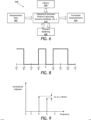
- FIG. 8 depicts an example transmitter waveform that may be used in accordance with the present disclosure.
- Preferred transmitter waveforms are doubly symmetric, as shown in FIG. 8 .
- Doubly symmetric waveforms may prove advantageous since they can be expressed in a discrete mathematical form which makes it possible to optimize the waveform for a given criteria.
- ⁇ is the number of transitions in the first quarter of the waveform
- the waveform can be optimized such that, for example: b 3 ⁇ b 5 ⁇ min which implies that the third and fifth harmonics have (approximately, if not identically) equal amplitude.
- This optimization can be performed subject to a number of tool-specific electronic and hardware parameters such as, but not limited to, waveform length, base frequency of the signal, transmitter switching frequency, transmitter ramp up and ramp down times (related to transmitter induction), receiver sampling frequency, at least two samples per transition (to satisfy the sampling theorem).
- the optimization may be performed by extensive parameter sweeping, or by a (global) stochastic search such as a Monte Carlo, simulated annealing, or genetic algorithm.
- one or more of the transmitter coils T1-T4 of FIG. 5 may be configured to transmit EM signals at multiple frequencies, and the receiver coils R1-R12 of FIG. 5 may likewise be configured to receive the EM signals at the multiple frequencies.
- one or more of the transmitter coils T1-T4 may comprise a broadband antenna with one or more signal filters used to transmit the EM signals at a predetermined one or more frequencies.
- the EM signals may be tuned to a particular or predetermined one or more frequencies.
- the associated transmitter coil T1-T4 would remain untuned (i.e., no filters), but a broadband pre-amplifier connected in parallel with a pair of filters may be included between the transmitter coil T1-T4 and the receiver coils R1-R12 to selectively tune the EM signals to desired frequencies to be received by the corresponding receiver coil R1-R12.
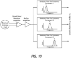
- FIG. 10 shows an exemplary circuit diagram and signal processing schematic, according to one or more embodiments.
- a broadband preamplifier may be connected to each receiver coil R1-R12, and the broadband amplifier may then be connected with two or more parallel bandpass filters.
- One bandpass filter may be included for each transmitted frequency f 1 , f 2 , f 3 , etc. As illustrated, the bandpass filter corresponding to a particular transmitted frequency f 1 -f 3 would have its bandpass centered at that frequency.
- antenna assemblies have been described herein with respect to MWD and/or LWD applications, it will be appreciated that the principles of the present disclosure are equally applicable to antenna assemblies (i.e., transmitters and/or receivers) permanently deployed behind casing, for example, and forming part of a reservoir monitoring system.
- Computer hardware used to implement the various illustrative blocks, modules, elements, components, methods, and algorithms described herein can include a processor configured to execute one or more sequences of instructions, programming stances, or code stored on a non-transitory, computer-readable medium.
- the processor can be, for example, a general purpose microprocessor, a microcontroller, a digital signal processor, an application specific integrated circuit, a field programmable gate array, a programmable logic device, a controller, a state machine, a gated logic, discrete hardware components, an artificial neural network, or any like suitable entity that can perform calculations or other manipulations of data.
- computer hardware can further include elements such as, for example, a memory (e.g., random access memory (RAM), flash memory, read only memory (ROM), programmable read only memory (PROM), erasable read only memory (EROM)), registers, hard disks, removable disks, CD-ROMS, DVDs, or any other like suitable storage device or medium.
- a memory e.g., random access memory (RAM), flash memory, read only memory (ROM), programmable read only memory (PROM), erasable read only memory (EROM)
- registers e.g., hard disks, removable disks, CD-ROMS, DVDs, or any other like suitable storage device or medium.
- Executable sequences described herein can be implemented with one or more sequences of code contained in the memory. In some embodiments, such code can be read into the memory from another machine-readable medium. Execution of the sequences of instructions contained in the memory can cause a processor to perform the process steps described herein. One or more processors in a multi-processing arrangement can also be employed to execute instruction sequences in the memory. In addition, hardwired circuitry can be used in place of or in combination with software instructions to implement various embodiments described herein. Thus, the present embodiments are not limited to any specific combination of hardware and/or software.
- a machine-readable medium will refer to any medium that directly or indirectly provides instructions to a processor for execution.
- a machine-readable medium can take on many forms including, for example, non-volatile media, volatile media, and transmission media.
- Non-volatile media can include, for example, optical and magnetic disks.
- Volatile media can include, for example, dynamic memory.
- Transmission media can include, for example, coaxial cables, wire, fiber optics, and wires that form a bus.
- Machine-readable media can include, for example, floppy disks, flexible disks, hard disks, magnetic tapes, other like magnetic media, CD-ROMs, DVDs, other like optical media, punch cards, paper tapes and like physical media with patterned holes, RAM, ROM, PROM, EPROM, and flash EPROM.
- the phrase "at least one of” preceding a series of items, with the terms “and” or “or” to separate any of the items, modifies the list as a whole, rather than each member of the list ( i.e ., each item).
- the phrase "at least one of” allows a meaning that includes at least one of any one of the items, and/or at least one of any combination of the items, and/or at least one of each of the items.
- the phrases “at least one of A, B, and C” or “at least one of A, B, or C” each refer to only A, only B, or only C; any combination of A, B, and C; and/or at least one of each of A, B, and C.
Claims (13)
- Procédé de diagraphie de puits de forage, comprenant :l'introduction d'un outil de diagraphie de résistivité (126, 400) comprenant une ou plusieurs bobines émettrices (T1-T4) et une ou plusieurs bobines réceptrices (R1-R12) dans un puits de forage ;la transmission d'un premier signal à une première fréquence et d'un deuxième signal à une deuxième fréquence différente de la première fréquence simultanément avec une première bobine émettrice à des amplitudes connues ;la réception avec une première bobine réceptrice d'un premier signal de réponse sur la base du premier signal à la première fréquence et d'un deuxième signal de réponse basé sur le deuxième signal à la deuxième fréquence, le premier signal de réponse et le deuxième signal de réponse étant reçus simultanément à la première fréquence et à la deuxième fréquence, respectivement ;le calcul d'un rapport entre les premier et deuxième signaux de réponse et donc l'obtention d'un signal de rapport ;le traitement du signal de rapport dans un algorithme d'inversion (610) ; etla détermination d'une ou plusieurs caractéristiques de formation (604) d'une formation souterraine entourant le puits de forage sur la base du signal de rapport tel que traité par l'algorithme d'inversion.
- Procédé selon la revendication 1, comprenant également :la transmission des premier et deuxième signaux avec une relation d'amplitude et de phase connue entre les premier et deuxième signaux, éventuellement,la mesure et la régulation d'au moins l'une parmi une phase et une amplitude des premier et deuxième signaux au niveau de la première bobine émettrice (T1-T4) garantissant ainsi la relation d'amplitude et de phase connue.
- Procédé selon l'une quelconque des revendications 1 et 2, comprenant également la transmission des premier et deuxième signaux avec une différence de phase connue entre les premier et deuxième signaux.
- Procédé selon l'une quelconque des revendications 1 à 3, comprenant également :la transmission d'un troisième signal à une troisième fréquence avec la première bobine émettrice (T1-T4) ;la réception d'un troisième signal de réponse sur la base du troisième signal avec la première bobine réceptrice (R1-R12) ; etle calcul du signal de rapport sur la base d'un rapport de deux des premier, deuxième et troisième signaux de réponse.
- Procédé selon la revendication 4, comprenant également la transmission des premier, deuxième et troisième signaux avec une relation d'amplitude et de phase connue entre les premier, deuxième et troisième signaux.
- Procédé selon l'une quelconque des revendications 1 à 5, dans lequel l'une ou les plusieurs caractéristiques de formation (604) de la formation souterraine sont sélectionnées dans le groupe constitué de la résistivité d'une couche de formation, d'une distance jusqu'à chaque couche de formation dans la formation souterraine, d'un nombre de couches dans la formation souterraine, un certain nombre de limites dans chaque couche de formation dans la formation souterraine, l'angle d'inclinaison par rapport à chaque couche de formation, la constante diélectrique, la perméabilité magnétique et l'anisotropie de la formation souterraine.
- Procédé selon l'une quelconque des revendications 1 à 6, comprenant également la génération d'un modèle visuel bidimensionnel ou tridimensionnel de la formation souterraine sur la base de l'une ou les plusieurs caractéristiques de formation (604).
- Procédé selon l'une quelconque des revendications 1 à 7, comprenant également la réception des premier et deuxième signaux de réponse azimutalement lorsque l'outil de diagraphie de résistivité (126, 400) tourne à l'intérieur du puits de forage.
- Procédé selon la revendication 8, dans lequel la première bobine réceptrice (R1-R12) est une bobine inclinée (406a-406c).
- Procédé selon l'une quelconque des revendications 1 à 9, dans lequel les premier et deuxième signaux aux première et deuxième fréquences comprennent une forme d'onde transmise, et sont séparés en réalisant une transformation de Fourier sur les formes d'onde reçues, éventuellement,
comprenant également l'optimisation de la forme d'onde en maximisant l'énergie distribuée à deux ou plusieurs fréquences harmoniques. - Système de puits de forage, comprenant :un outil de diagraphie de résistivité (126, 400) transportable dans un puits de forage et comprenant une ou plusieurs bobines émettrices (T1-T4) et une ou plusieurs bobines réceptrices (R1-R12),l'une ou les plusieurs bobines émettrices étant configurées pour transmettre un premier signal à une première fréquence et un deuxième signal à une deuxième fréquence différente de la première fréquence avec une première bobine émettrice, le premier signal et le deuxième signal étant transmis simultanément avec des amplitudes connues etl'une ou les plusieurs bobines réceptrices étant configurées pour recevoir avec une première bobine réceptrice un premier signal de réponse sur la base du premier signal à la première fréquence et un deuxième signal de réponse sur la base du deuxième signal à la deuxième fréquence, le premier signal de réponse et le deuxième signal de réponse étant reçus simultanément ; etun système informatique comprenant un processeur et un support lisible par ordinateur non transitoire, le système informatique étant couplé en communication à l'outil de diagraphie de résistivité, et le support lisible par ordinateur stockant un code de programme lisible par ordinateur qui, lorsqu'il est exécuté par le processeur, configure le processeur pour :le calcul d'un rapport entre les premier et deuxième signaux de réponse et donc l'obtention d'un signal de rapport ;le traitement du signal de rapport dans un algorithme d'inversion (610) ; etla détermination d'une ou plusieurs caractéristiques de formation (604) d'une formation souterraine entourant le puits de forage sur la base du signal de rapport tel que traité par l'algorithme d'inversion.
- Système de puits selon la revendication 11, dans lequel la première bobine émettrice (T1-T4) comprend une antenne à large bande avec un ou plusieurs filtres de signal utilisés pour transmettre les premier et deuxième signaux aux première et deuxième fréquences, respectivement.
- Système de puits selon l'une quelconque des revendications 11 à 12, comprenant également un préamplificateur à large bande connecté à l'une ou les plusieurs bobines réceptrices (R1-R12) et deux ou plusieurs filtres passe-bande parallèles pour accorder sélectivement les premier et deuxième signaux aux première et deuxième fréquences, respectivement.
Applications Claiming Priority (1)
| Application Number | Priority Date | Filing Date | Title |
|---|---|---|---|
| PCT/US2015/057311 WO2017074295A1 (fr) | 2015-10-26 | 2015-10-26 | Traitement ratiométrique de fréquence de données d'outil de diagraphie de résistivité |
Publications (3)
| Publication Number | Publication Date |
|---|---|
| EP3337951A1 EP3337951A1 (fr) | 2018-06-27 |
| EP3337951A4 EP3337951A4 (fr) | 2018-09-12 |
| EP3337951B1 true EP3337951B1 (fr) | 2023-11-29 |
Family
ID=58631968
Family Applications (1)
| Application Number | Title | Priority Date | Filing Date |
|---|---|---|---|
| EP15907405.3A Active EP3337951B1 (fr) | 2015-10-26 | 2015-10-26 | Traitement ratiométrique de fréquence de données d'outil de diagraphie de résistivité |
Country Status (3)
| Country | Link |
|---|---|
| US (1) | US10317563B2 (fr) |
| EP (1) | EP3337951B1 (fr) |
| WO (1) | WO2017074295A1 (fr) |
Families Citing this family (20)
| Publication number | Priority date | Publication date | Assignee | Title |
|---|---|---|---|---|
| AU2013403952B2 (en) * | 2013-10-31 | 2017-06-15 | Halliburton Energy Services, Inc. | Downhole acoustic ranging utilizing gradiometric data |
| US10811908B2 (en) | 2014-09-25 | 2020-10-20 | Supply, Inc. | System and method for wireless power reception |
| US9857499B2 (en) * | 2016-02-19 | 2018-01-02 | Baker Hughes, A Ge Company, Llc | Downhole transient resistivity measurements |
| WO2018125099A1 (fr) * | 2016-12-28 | 2018-07-05 | Halliburton Energy Services, Inc. | Télémesure de puits de production dévié ayant un puits/navire de forage d'assistance |
| US11099293B2 (en) | 2017-05-08 | 2021-08-24 | Halliburton Energy Services. Inc. | System and method for evaluating a formation using a statistical distribution of formation data |
| US11178625B2 (en) | 2017-06-06 | 2021-11-16 | Supply, Inc. | Method and system for wireless power delivery |
| US10798665B2 (en) | 2017-06-06 | 2020-10-06 | Supply, Inc. | Method and system for wireless power delivery |
| JP6921246B2 (ja) | 2017-06-06 | 2021-08-18 | サプライ, インコーポレイテッドSupply, Inc. | ワイヤレス電力供給方法およびシステム |
| US10778044B2 (en) | 2018-11-30 | 2020-09-15 | Supply, Inc. | Methods and systems for multi-objective optimization and/or wireless power delivery |
| WO2019173590A1 (fr) | 2018-03-08 | 2019-09-12 | Supply, Inc. | Procédé et système de distribution de puissance sans fil |
| US11269098B2 (en) * | 2018-08-31 | 2022-03-08 | Halliburton Energy Services, Inc. | Sparse deconvolution and inversion for formation properties |
| US10820283B2 (en) | 2018-11-28 | 2020-10-27 | Supply, Inc. | System and method for wireless power delivery |
| CN110242292A (zh) * | 2019-07-15 | 2019-09-17 | 北京华晖盛世能源技术股份有限公司 | 一种裸眼井地层垂直方向电阻率测量装置、方法及系统 |
| US11215733B2 (en) | 2019-11-22 | 2022-01-04 | Halliburton Energy Services, Inc. | Methods to configure a downhole electromagnetic tool and downhole electromagnetic tool calibration systems |
| US11543552B2 (en) * | 2019-12-20 | 2023-01-03 | Halliburton Energy Services, Inc. | Determining distance to bed boundary uncertainty for borehole drilling |
| CN112177602B (zh) * | 2020-09-27 | 2022-09-09 | 电子科技大学 | 一种超深电阻率测井的时域测量方法 |
| CN112160744B (zh) * | 2020-09-27 | 2022-09-09 | 电子科技大学 | 一种超深电阻率的测量装置 |
| CN112160746B (zh) * | 2020-09-27 | 2022-09-09 | 电子科技大学 | 一种超深电阻率测井的时域测量装置 |
| WO2022221435A1 (fr) | 2021-04-14 | 2022-10-20 | Supply, Inc. | Système et procédé de mise en réseau électrique sans fil |
| CN114675337A (zh) * | 2022-03-22 | 2022-06-28 | 扬州蓝德森科技有限公司 | 一种基于多匝线圈和瞬变电磁法的地下测深方法 |
Citations (4)
| Publication number | Priority date | Publication date | Assignee | Title |
|---|---|---|---|---|
| GB2322199A (en) * | 1994-03-11 | 1998-08-19 | Baker Hughes Inc | A borehole measuring system employing electromagnetic wave propagation |
| US6147496A (en) * | 1996-07-01 | 2000-11-14 | Shell Oil Company | Determining electrical conductivity of a laminated earth formation using induction logging |
| US20110199088A1 (en) * | 1999-01-28 | 2011-08-18 | Halliburton Energy Services, Inc. | Electromagnetic Wave Resistivity Tool Having A Tilted Antenna For Determining The Horizontal And Vertical Resistivities And Relative Dip Angle In Anisotropic Earth Formations |
| WO2014172296A2 (fr) * | 2013-04-17 | 2014-10-23 | Services Petroliers Schlumberger | Compensation de mesures à l'aide de plusieurs émetteurs électromagnétiques |
Family Cites Families (41)
| Publication number | Priority date | Publication date | Assignee | Title |
|---|---|---|---|---|
| US3967190A (en) | 1974-12-23 | 1976-06-29 | Zonge Kenneth L | Method using induced polarization for ore discrimination in disseminated earth deposits |
| US4730161A (en) | 1986-09-22 | 1988-03-08 | Texaco Inc. | Dual frequency well logging system for determining the water resistivity and water saturation of an earth formation |
| US5157605A (en) * | 1987-04-27 | 1992-10-20 | Schlumberger Technology Corporation | Induction logging method and apparatus including means for combining on-phase and quadrature components of signals received at varying frequencies and including use of multiple receiver means associated with a single transmitter |
| US4893084A (en) * | 1988-05-19 | 1990-01-09 | Halliburton Logging Services, Inc. | Formation electromagnetic parameters measuring tool using transmitter reference and reflected signals and a received signal |
| US5278507A (en) | 1991-06-14 | 1994-01-11 | Baroid Technology, Inc. | Well logging method and apparatus providing multiple depth of investigation using multiple transmitters and single receiver pair having depth of investigation independent of formation resistivity |
| US5389881A (en) | 1992-07-22 | 1995-02-14 | Baroid Technology, Inc. | Well logging method and apparatus involving electromagnetic wave propagation providing variable depth of investigation by combining phase angle and amplitude attenuation |
| US5469062A (en) * | 1994-03-11 | 1995-11-21 | Baker Hughes, Inc. | Multiple depths and frequencies for simultaneous inversion of electromagnetic borehole measurements |
| US6188222B1 (en) | 1997-09-19 | 2001-02-13 | Schlumberger Technology Corporation | Method and apparatus for measuring resistivity of an earth formation |
| US6476609B1 (en) | 1999-01-28 | 2002-11-05 | Dresser Industries, Inc. | Electromagnetic wave resistivity tool having a tilted antenna for geosteering within a desired payzone |
| US6181138B1 (en) | 1999-02-22 | 2001-01-30 | Halliburton Energy Services, Inc. | Directional resistivity measurements for azimuthal proximity detection of bed boundaries |
| US6218842B1 (en) | 1999-08-04 | 2001-04-17 | Halliburton Energy Services, Inc. | Multi-frequency electromagnetic wave resistivity tool with improved calibration measurement |
| US6304086B1 (en) * | 1999-09-07 | 2001-10-16 | Schlumberger Technology Corporation | Method and apparatus for evaluating the resistivity of formations with high dip angles or high-contrast thin layers |
| US6294917B1 (en) | 1999-09-13 | 2001-09-25 | Electromagnetic Instruments, Inc. | Electromagnetic induction method and apparatus for the measurement of the electrical resistivity of geologic formations surrounding boreholes cased with a conductive liner |
| US6703837B1 (en) * | 2000-09-15 | 2004-03-09 | Precision Drilling Technology Services Group, Inc. | Wellbore resistivity tool with simultaneous multiple frequencies |
| US6791330B2 (en) * | 2002-07-16 | 2004-09-14 | General Electric Company | Well logging tool and method for determining resistivity by using phase difference and/or attenuation measurements |
| US7539279B2 (en) | 2004-05-20 | 2009-05-26 | Exxonmobil Upstream Research Company | Logarithmic spectrum transmitter waveform for controlled-source electromagnetic surveying |
| US8736270B2 (en) | 2004-07-14 | 2014-05-27 | Schlumberger Technology Corporation | Look ahead logging system |
| US7825664B2 (en) | 2004-07-14 | 2010-11-02 | Schlumberger Technology Corporation | Resistivity tool with selectable depths of investigation |
| US7786733B2 (en) | 2004-07-14 | 2010-08-31 | Schlumberger Technology Corporation | Apparatus and system for well placement and reservoir characterization |
| US7755361B2 (en) | 2004-07-14 | 2010-07-13 | Schlumberger Technology Corporation | Apparatus and system for well placement and reservoir characterization |
| US7141981B2 (en) | 2004-07-23 | 2006-11-28 | Baker Hughes Incorporated | Error correction and calibration of a deep reading propagation resistivity tool |
| DE602005004123D1 (de) * | 2005-04-26 | 2008-02-14 | Schlumberger Technology Bv | Verfahren für die elektromagnetische Messung von physikalischen Parametern eines Rohrs |
| US7483793B2 (en) | 2005-07-27 | 2009-01-27 | Baker Hughes Incorporated | Method of generating a deep resistivity image in LWD measurements |
| WO2007055784A2 (fr) | 2005-11-04 | 2007-05-18 | Halliburton Energy Services, Inc. | Outil de mise en image de boue a base d'huiles qui mesure la phase et l'amplitude de tension |
| US7579841B2 (en) | 2005-11-04 | 2009-08-25 | Halliburton Energy Services, Inc. | Standoff compensation for imaging in oil-based muds |
| US7696756B2 (en) | 2005-11-04 | 2010-04-13 | Halliburton Energy Services, Inc. | Oil based mud imaging tool with common mode voltage compensation |
| US7966874B2 (en) | 2006-09-28 | 2011-06-28 | Baker Hughes Incorporated | Multi-resolution borehole profiling |
| US7548817B2 (en) | 2006-09-28 | 2009-06-16 | Baker Hughes Incorporated | Formation evaluation using estimated borehole tool position |
| US8015868B2 (en) | 2007-09-27 | 2011-09-13 | Baker Hughes Incorporated | Formation evaluation using estimated borehole tool position |
| US8190369B2 (en) | 2006-09-28 | 2012-05-29 | Baker Hughes Incorporated | System and method for stress field based wellbore steering |
| EP2066866B1 (fr) * | 2006-12-15 | 2018-09-12 | Halliburton Energy Services, Inc. | Outil de mesure de composant de couplage d'antenne doté d'une configuration d'antenne rotative |
| BRPI0711465B1 (pt) | 2007-03-16 | 2018-04-24 | Halliburton Energy Services, Inc. | ferramenta de perfilagem, e, método para ferramenta de perfilagem de resistividade azimutalmente sensível |
| BRPI0815932A2 (pt) | 2007-08-27 | 2018-01-09 | Prad Research And Development Limited | sistema para uso em um poço, método para determinar a presença e posição de um ou mais contrastes de resistividade em uma formação à frente de um sistema de perfuração de poço, método para determinar uma propriedade de uma formação a diante de um sistema de perfuração de poço. |
| CN101688924B (zh) | 2008-04-08 | 2017-02-22 | 哈里伯顿能源服务公司 | 具有用于油基泥浆中的成像的高分辨率电极配置的方法和装置 |
| US8466682B2 (en) | 2009-09-29 | 2013-06-18 | Schlumberger Technology Corporation | Apparatus and method for downhole electromagnetic measurement while drilling |
| CA2855305C (fr) | 2011-11-15 | 2017-02-28 | Halliburton Energy Services, Inc. | Appareil, procedes et systemes de mesure de resistivite amelioree |
| AU2011381036B2 (en) | 2011-11-15 | 2015-08-13 | Halliburton Energy Services, Inc. | Look-ahead of the bit applications |
| US8862405B2 (en) | 2011-12-06 | 2014-10-14 | Schlumberger Technology Corporation | System and method for producing look-ahead profile measurements in a drilling operation |
| US9638819B2 (en) | 2013-06-18 | 2017-05-02 | Well Resolutions Technology | Modular resistivity sensor for downhole measurement while drilling |
| US10444404B2 (en) | 2013-07-26 | 2019-10-15 | Halliburton Energy Services Inc. | System, method and computer-program product for in-situ calibration of a wellbore resistivity logging tool |
| CA2926227A1 (fr) | 2013-10-04 | 2015-04-09 | Schlumberger Canada Limited | Procedes et appareils de production d'un modele de formation |
-
2015
- 2015-10-26 WO PCT/US2015/057311 patent/WO2017074295A1/fr active Application Filing
- 2015-10-26 EP EP15907405.3A patent/EP3337951B1/fr active Active
- 2015-10-26 US US15/121,222 patent/US10317563B2/en active Active
Patent Citations (4)
| Publication number | Priority date | Publication date | Assignee | Title |
|---|---|---|---|---|
| GB2322199A (en) * | 1994-03-11 | 1998-08-19 | Baker Hughes Inc | A borehole measuring system employing electromagnetic wave propagation |
| US6147496A (en) * | 1996-07-01 | 2000-11-14 | Shell Oil Company | Determining electrical conductivity of a laminated earth formation using induction logging |
| US20110199088A1 (en) * | 1999-01-28 | 2011-08-18 | Halliburton Energy Services, Inc. | Electromagnetic Wave Resistivity Tool Having A Tilted Antenna For Determining The Horizontal And Vertical Resistivities And Relative Dip Angle In Anisotropic Earth Formations |
| WO2014172296A2 (fr) * | 2013-04-17 | 2014-10-23 | Services Petroliers Schlumberger | Compensation de mesures à l'aide de plusieurs émetteurs électromagnétiques |
Also Published As
| Publication number | Publication date |
|---|---|
| EP3337951A4 (fr) | 2018-09-12 |
| US10317563B2 (en) | 2019-06-11 |
| EP3337951A1 (fr) | 2018-06-27 |
| WO2017074295A1 (fr) | 2017-05-04 |
| US20170261631A1 (en) | 2017-09-14 |
Similar Documents
| Publication | Publication Date | Title |
|---|---|---|
| EP3337951B1 (fr) | Traitement ratiométrique de fréquence de données d'outil de diagraphie de résistivité | |
| US7236886B2 (en) | Multiscale multidimensional well log data inversion and deep formation imaging method | |
| US6534986B2 (en) | Permanently emplaced electromagnetic system and method for measuring formation resistivity adjacent to and between wells | |
| US7619540B2 (en) | Apparatus and methods for determining isotropic and anisotropic formation resistivity in the presence of invasion | |
| CA2861665C (fr) | Detection d'emplacements limites de multiples couches de subsurface | |
| US10451765B2 (en) | Post-well reservoir characterization using image-constrained inversion | |
| US6925384B2 (en) | Method for resistivity anisotropy determination in conductive borehole environments | |
| US6950749B2 (en) | Method for resistivity anisotropy determination in near vertical wells | |
| EP2780744B1 (fr) | Procédés et systèmes d'analyse de propriétés de formations lors de la réalisation d'opérations souterraines | |
| US7505851B2 (en) | Use of multi-component measurements in delineating geology of deep-water sediments | |
| US10495780B2 (en) | Correcting shale volume and measuring anisotropy in invaded zone | |
| US9194830B2 (en) | Correction for gain variation due to fast changing NMR sensor gain | |
| US11768306B2 (en) | Enhanced anisotropy analysis with multicomponent dipole sonic data | |
| NO20180767A1 (en) | Methods to synchronize signals among antennas with different clock systems | |
| NO20120282A1 (no) | Forover-fokuseringssystem med elektromagnetiske målinger i tidsdomene for bruk i en brønnboring | |
| US20200033502A1 (en) | Identifying antenna system parameter changes | |
| US10508535B2 (en) | Method for steering a well path perpendicular to vertical fractures for enhanced production efficiency | |
| Gonfalini et al. | Array induction measurements in complex environments: a comparison between AIT and HDIL responses | |
| Ellis et al. | Other Electrode and Toroid Devices |
Legal Events
| Date | Code | Title | Description |
|---|---|---|---|
| STAA | Information on the status of an ep patent application or granted ep patent |
Free format text: STATUS: THE INTERNATIONAL PUBLICATION HAS BEEN MADE |
|
| PUAI | Public reference made under article 153(3) epc to a published international application that has entered the european phase |
Free format text: ORIGINAL CODE: 0009012 |
|
| STAA | Information on the status of an ep patent application or granted ep patent |
Free format text: STATUS: REQUEST FOR EXAMINATION WAS MADE |
|
| 17P | Request for examination filed |
Effective date: 20180322 |
|
| AK | Designated contracting states |
Kind code of ref document: A1 Designated state(s): AL AT BE BG CH CY CZ DE DK EE ES FI FR GB GR HR HU IE IS IT LI LT LU LV MC MK MT NL NO PL PT RO RS SE SI SK SM TR |
|
| AX | Request for extension of the european patent |
Extension state: BA ME |
|
| RIN1 | Information on inventor provided before grant (corrected) |
Inventor name: SONG, RENCHENG Inventor name: WILSON, GLENN ANDREW Inventor name: DONDERICI, BURKAY Inventor name: RODNEY, PAUL F. |
|
| A4 | Supplementary search report drawn up and despatched |
Effective date: 20180810 |
|
| RIC1 | Information provided on ipc code assigned before grant |
Ipc: G01V 3/26 20060101ALI20180806BHEP Ipc: G01V 3/38 20060101ALI20180806BHEP Ipc: E21B 47/00 20120101AFI20180806BHEP Ipc: G01V 3/18 20060101ALI20180806BHEP Ipc: G01V 3/28 20060101ALI20180806BHEP |
|
| DAV | Request for validation of the european patent (deleted) | ||
| DAX | Request for extension of the european patent (deleted) | ||
| STAA | Information on the status of an ep patent application or granted ep patent |
Free format text: STATUS: EXAMINATION IS IN PROGRESS |
|
| 17Q | First examination report despatched |
Effective date: 20200429 |
|
| STAA | Information on the status of an ep patent application or granted ep patent |
Free format text: STATUS: EXAMINATION IS IN PROGRESS |
|
| STAA | Information on the status of an ep patent application or granted ep patent |
Free format text: STATUS: EXAMINATION IS IN PROGRESS |
|
| P01 | Opt-out of the competence of the unified patent court (upc) registered |
Effective date: 20230530 |
|
| GRAP | Despatch of communication of intention to grant a patent |
Free format text: ORIGINAL CODE: EPIDOSNIGR1 |
|
| STAA | Information on the status of an ep patent application or granted ep patent |
Free format text: STATUS: GRANT OF PATENT IS INTENDED |
|
| INTG | Intention to grant announced |
Effective date: 20230718 |
|
| GRAS | Grant fee paid |
Free format text: ORIGINAL CODE: EPIDOSNIGR3 |
|
| GRAA | (expected) grant |
Free format text: ORIGINAL CODE: 0009210 |
|
| STAA | Information on the status of an ep patent application or granted ep patent |
Free format text: STATUS: THE PATENT HAS BEEN GRANTED |
|
| AK | Designated contracting states |
Kind code of ref document: B1 Designated state(s): AL AT BE BG CH CY CZ DE DK EE ES FI FR GB GR HR HU IE IS IT LI LT LU LV MC MK MT NL NO PL PT RO RS SE SI SK SM TR |
|
| REG | Reference to a national code |
Ref country code: GB Ref legal event code: FG4D |
|
| REG | Reference to a national code |
Ref country code: CH Ref legal event code: EP |
|
| REG | Reference to a national code |
Ref country code: DE Ref legal event code: R096 Ref document number: 602015086778 Country of ref document: DE |
|
| REG | Reference to a national code |
Ref country code: IE Ref legal event code: FG4D |
|
| REG | Reference to a national code |
Ref country code: NO Ref legal event code: T2 Effective date: 20231129 |
|
| REG | Reference to a national code |
Ref country code: LT Ref legal event code: MG9D |
|
| REG | Reference to a national code |
Ref country code: NL Ref legal event code: MP Effective date: 20231129 |
|
| PG25 | Lapsed in a contracting state [announced via postgrant information from national office to epo] |
Ref country code: GR Free format text: LAPSE BECAUSE OF FAILURE TO SUBMIT A TRANSLATION OF THE DESCRIPTION OR TO PAY THE FEE WITHIN THE PRESCRIBED TIME-LIMIT Effective date: 20240301 |
|
| PG25 | Lapsed in a contracting state [announced via postgrant information from national office to epo] |
Ref country code: IS Free format text: LAPSE BECAUSE OF FAILURE TO SUBMIT A TRANSLATION OF THE DESCRIPTION OR TO PAY THE FEE WITHIN THE PRESCRIBED TIME-LIMIT Effective date: 20240329 |
|
| PG25 | Lapsed in a contracting state [announced via postgrant information from national office to epo] |
Ref country code: LT Free format text: LAPSE BECAUSE OF FAILURE TO SUBMIT A TRANSLATION OF THE DESCRIPTION OR TO PAY THE FEE WITHIN THE PRESCRIBED TIME-LIMIT Effective date: 20231129 |
|
| PG25 | Lapsed in a contracting state [announced via postgrant information from national office to epo] |
Ref country code: ES Free format text: LAPSE BECAUSE OF FAILURE TO SUBMIT A TRANSLATION OF THE DESCRIPTION OR TO PAY THE FEE WITHIN THE PRESCRIBED TIME-LIMIT Effective date: 20231129 |
|
| PG25 | Lapsed in a contracting state [announced via postgrant information from national office to epo] |
Ref country code: LT Free format text: LAPSE BECAUSE OF FAILURE TO SUBMIT A TRANSLATION OF THE DESCRIPTION OR TO PAY THE FEE WITHIN THE PRESCRIBED TIME-LIMIT Effective date: 20231129 Ref country code: IS Free format text: LAPSE BECAUSE OF FAILURE TO SUBMIT A TRANSLATION OF THE DESCRIPTION OR TO PAY THE FEE WITHIN THE PRESCRIBED TIME-LIMIT Effective date: 20240329 Ref country code: GR Free format text: LAPSE BECAUSE OF FAILURE TO SUBMIT A TRANSLATION OF THE DESCRIPTION OR TO PAY THE FEE WITHIN THE PRESCRIBED TIME-LIMIT Effective date: 20240301 Ref country code: ES Free format text: LAPSE BECAUSE OF FAILURE TO SUBMIT A TRANSLATION OF THE DESCRIPTION OR TO PAY THE FEE WITHIN THE PRESCRIBED TIME-LIMIT Effective date: 20231129 Ref country code: BG Free format text: LAPSE BECAUSE OF FAILURE TO SUBMIT A TRANSLATION OF THE DESCRIPTION OR TO PAY THE FEE WITHIN THE PRESCRIBED TIME-LIMIT Effective date: 20240229 |