EP3337252A1 - Terminal d'utilisateur, station de base sans fil et procédé de communication sans fil - Google Patents
Terminal d'utilisateur, station de base sans fil et procédé de communication sans fil Download PDFInfo
- Publication number
- EP3337252A1 EP3337252A1 EP16835131.0A EP16835131A EP3337252A1 EP 3337252 A1 EP3337252 A1 EP 3337252A1 EP 16835131 A EP16835131 A EP 16835131A EP 3337252 A1 EP3337252 A1 EP 3337252A1
- Authority
- EP
- European Patent Office
- Prior art keywords
- sss
- synchronization signal
- transmitted
- signals
- user terminal
- Prior art date
- Legal status (The legal status is an assumption and is not a legal conclusion. Google has not performed a legal analysis and makes no representation as to the accuracy of the status listed.)
- Withdrawn
Links
- 238000004891 communication Methods 0.000 title claims abstract description 47
- 238000000034 method Methods 0.000 title claims description 52
- 230000005540 biological transmission Effects 0.000 claims description 71
- 239000000969 carrier Substances 0.000 abstract description 9
- 238000010586 diagram Methods 0.000 description 57
- 238000005259 measurement Methods 0.000 description 46
- 210000004027 cell Anatomy 0.000 description 42
- 238000012545 processing Methods 0.000 description 42
- 238000013507 mapping Methods 0.000 description 33
- 230000008569 process Effects 0.000 description 26
- 230000011664 signaling Effects 0.000 description 10
- 201000000913 Duane retraction syndrome Diseases 0.000 description 8
- 238000000162 direct recoil spectroscopy Methods 0.000 description 8
- 238000010295 mobile communication Methods 0.000 description 7
- 210000000678 band cell Anatomy 0.000 description 6
- 238000005516 engineering process Methods 0.000 description 5
- 230000006870 function Effects 0.000 description 5
- 238000012384 transportation and delivery Methods 0.000 description 5
- 238000006243 chemical reaction Methods 0.000 description 4
- 230000007246 mechanism Effects 0.000 description 4
- 238000001228 spectrum Methods 0.000 description 4
- 230000001360 synchronised effect Effects 0.000 description 4
- 238000012937 correction Methods 0.000 description 3
- 238000007726 management method Methods 0.000 description 3
- 239000013307 optical fiber Substances 0.000 description 3
- 238000003860 storage Methods 0.000 description 3
- 102100036409 Activated CDC42 kinase 1 Human genes 0.000 description 2
- 101000741965 Homo sapiens Inactive tyrosine-protein kinase PRAG1 Proteins 0.000 description 2
- 102100038659 Inactive tyrosine-protein kinase PRAG1 Human genes 0.000 description 2
- 230000002776 aggregation Effects 0.000 description 2
- 238000004220 aggregation Methods 0.000 description 2
- 230000009977 dual effect Effects 0.000 description 2
- 230000000694 effects Effects 0.000 description 2
- 230000007774 longterm Effects 0.000 description 2
- 201000003042 peeling skin syndrome Diseases 0.000 description 2
- 229920001467 poly(styrenesulfonates) Polymers 0.000 description 2
- 238000003491 array Methods 0.000 description 1
- 230000008859 change Effects 0.000 description 1
- 230000008878 coupling Effects 0.000 description 1
- 238000010168 coupling process Methods 0.000 description 1
- 238000005859 coupling reaction Methods 0.000 description 1
- 125000004122 cyclic group Chemical group 0.000 description 1
- 230000001934 delay Effects 0.000 description 1
- 238000013461 design Methods 0.000 description 1
- 238000001514 detection method Methods 0.000 description 1
- 208000028626 extracranial carotid artery aneurysm Diseases 0.000 description 1
- 238000004519 manufacturing process Methods 0.000 description 1
- 238000012986 modification Methods 0.000 description 1
- 230000004048 modification Effects 0.000 description 1
- 230000003287 optical effect Effects 0.000 description 1
- 239000002245 particle Substances 0.000 description 1
- 230000005855 radiation Effects 0.000 description 1
- 238000013468 resource allocation Methods 0.000 description 1
- 230000004044 response Effects 0.000 description 1
- 238000001774 stimulated Raman spectroscopy Methods 0.000 description 1
Images


Classifications
-
- H—ELECTRICITY
- H04—ELECTRIC COMMUNICATION TECHNIQUE
- H04W—WIRELESS COMMUNICATION NETWORKS
- H04W74/00—Wireless channel access
- H04W74/08—Non-scheduled access, e.g. ALOHA
- H04W74/0866—Non-scheduled access, e.g. ALOHA using a dedicated channel for access
- H04W74/0891—Non-scheduled access, e.g. ALOHA using a dedicated channel for access for synchronized access
-
- H—ELECTRICITY
- H04—ELECTRIC COMMUNICATION TECHNIQUE
- H04W—WIRELESS COMMUNICATION NETWORKS
- H04W56/00—Synchronisation arrangements
- H04W56/001—Synchronization between nodes
-
- H—ELECTRICITY
- H04—ELECTRIC COMMUNICATION TECHNIQUE
- H04W—WIRELESS COMMUNICATION NETWORKS
- H04W16/00—Network planning, e.g. coverage or traffic planning tools; Network deployment, e.g. resource partitioning or cells structures
- H04W16/14—Spectrum sharing arrangements between different networks
-
- H—ELECTRICITY
- H04—ELECTRIC COMMUNICATION TECHNIQUE
- H04W—WIRELESS COMMUNICATION NETWORKS
- H04W56/00—Synchronisation arrangements
-
- H—ELECTRICITY
- H04—ELECTRIC COMMUNICATION TECHNIQUE
- H04W—WIRELESS COMMUNICATION NETWORKS
- H04W72/00—Local resource management
- H04W72/04—Wireless resource allocation
-
- H—ELECTRICITY
- H04—ELECTRIC COMMUNICATION TECHNIQUE
- H04W—WIRELESS COMMUNICATION NETWORKS
- H04W72/00—Local resource management
- H04W72/20—Control channels or signalling for resource management
- H04W72/23—Control channels or signalling for resource management in the downlink direction of a wireless link, i.e. towards a terminal
-
- H—ELECTRICITY
- H04—ELECTRIC COMMUNICATION TECHNIQUE
- H04W—WIRELESS COMMUNICATION NETWORKS
- H04W74/00—Wireless channel access
- H04W74/08—Non-scheduled access, e.g. ALOHA
- H04W74/0808—Non-scheduled access, e.g. ALOHA using carrier sensing, e.g. carrier sense multiple access [CSMA]
-
- H—ELECTRICITY
- H04—ELECTRIC COMMUNICATION TECHNIQUE
- H04W—WIRELESS COMMUNICATION NETWORKS
- H04W8/00—Network data management
- H04W8/005—Discovery of network devices, e.g. terminals
Definitions
- the present invention relates to a user terminal, a radio base station and a radio communication method in next-generation mobile communication systems.
- LTE Long term evolution
- FRA Full Radio Access
- 5G 5th generation mobile communication system
- UE User Equipment
- licensed bands have limited spectra (licensed spectra).
- unlicensed bands bands of unlicensed spectra
- licensed bands for example, the 2.4 GHz band and the 5 GHz band, where Wi-Fi (registered trademark) and Bluetooth (registered trademark) can be used, are under study for use.
- CA carrier aggregation
- LBT Listen Before Talk
- CCA Carrier Channel Assessment
- the subframe to transmit the DS changes depending on the result of LBT, so that a UE cannot establish frame timing synchronization based on the DS received in the UE. Consequently, it becomes difficult to conduct cell search and/or RRM measurements in LAA accurately (with high reliability), and there is a threat that adequate communication is not possible.
- the present invention has been made in view of the above, and it is therefore an object of the present invention to provide a user terminal, a radio base station and a radio communication method that allow adequate communication even in carriers (for example, unlicensed bands) that execute LBT (pre-transmission listening).
- a user terminal communicates by using a cell in which listening is executed before signals are transmitted, and has a receiving section that receives a discovery signal, which includes a first synchronization signal and a second synchronization signal, and a control section that specifies an index of a subframe, in which the second synchronization signal is received, and the second synchronization signal is a different signal from an SSS (Secondary Synchronization Signal) used in an existing system.
- SSS Secondary Synchronization Signal
- LAA In systems (for example, LAA systems) that run LTE/LTE-A in unlicensed bands, interference control functionality is likely to be necessary in order to allow co-presence with other operators' LTE, Wi-Fi, or other different systems.
- systems that run LTE/LTE-A in unlicensed bands may be collectively referred to as "LAA,” “LAA-LTE,” “LTE-U,” “U-LTE” and so on, regardless of whether the mode of operation is CA, DC or SA.
- a transmission point for example, a radio base station (eNB), a user terminal (UE) and so on
- a carrier which may also be referred to as a "carrier frequency,” or simply a "frequency”
- the transmission point is disallowed to make transmission in this carrier.
- the transmission point executes listening (LBT) at a timing that is a predetermined period ahead of a transmission timing.
- LBT listening
- the transmission point searches the whole applicable carrier band (for example, one component carrier (CC)) at a timing that is a predetermined period ahead of a transmission timing, and checks whether or not other devices (for example, radio base stations, UEs, Wi-Fi devices and so on) are communicating in this carrier band.
- CC component carrier
- listening refers to the operation which a given transmission point (for example, a radio base station, a user terminal, etc.) performs before transmitting signals in order to check whether or not signals to exceed a predetermined level (for example, predetermined power) are being transmitted from other transmission points.
- a predetermined level for example, predetermined power
- this "listening" performed by radio base stations and/or user terminals may be referred to as “LBT,” “CCA,” “carrier sensing” and so on.
- the transmission point carries out transmission using this carrier. If the received power measured during LBT (the received signal power during the LBT period) is equal to or lower than a predetermined threshold, the transmission point judges that the channel is in the idle state (LBT idle ), and carries out transmission.
- LBT idle the idle state
- the transmission point stops its transmission. For example, if the transmission point detects that the received power of a signal from another device entering this band exceeds a predetermined threshold, the transmission point judges that the channel is in the busy state (LBT busy ), and makes no transmission. In the event LBT busy is yielded, LBT is carried out again with respect to this channel, and the channel becomes available for use only after it is confirmed that the channel is in the idle state. Note that the method of judging whether a channel is in the idle state/busy state based on LBT is by no means limited to this.
- LBT mechanisms Schemes
- FBE Full Based Equipment
- LBE Low Based Equipment
- Differences between these include the frame configurations to use for transmission/receipt, the channel-occupying time, and so on.
- FBE the LBT-related transmitting/receiving configurations have fixed timings.
- LBE the LBT-related transmitting/receiving configurations are not fixed in the time direction, and LBT is carried out on an as-needed basis.
- FBE has a fixed frame cycle, and is a mechanism of carrying out transmission if the result of executing carrier sensing for a certain period (which may be referred to as "LBT time,” “LBT duration” and so on) in a predetermined frame shows that a channel is available for use, and not making transmission but waiting until the next carrier sensing timing if no channel is available.
- LBE refers to a mechanism for implementing the ECCA (Extended CCA) procedure of extending the duration of carrier sensing when the result of carrier sensing (initial CCA) shows that no channel is available for use, and continuing executing carrier sensing until a channel is available.
- ECCA Extended CCA
- random backoff is required to adequately avoid contention.
- the duration of carrier sensing refers to the time (for example, the duration of one symbol) it takes to gain one LBT result by performing listening and/or other processes and deciding whether or not a channel can be used.
- a transmission point can transmit a predetermined signal (for example, a channel reservation signal) based on the result of LBT.
- a predetermined signal for example, a channel reservation signal
- the result of LBT refers to information about the state of channel availability (for example, "LBT idle ,” “LBT busy ,” etc.), which is acquired by LBT in carriers where LBT is configured.
- interference control for use within the same frequency that is based on LBT mechanisms to transmission points in LAA systems, it is possible to prevent interference between LAA and Wi-Fi, interference between LAA systems and so on. Furthermore, even when transmission points are controlled independently per operator that runs an LAA system, it is possible to reduce interference without learning the details of each operator's control, by means of LBT.
- a UE has to detect SCells that are present in the surroundings by means of RRM (Radio Resource Management) measurements, measure their received quality, and then send a report to the network.
- RRM Radio Resource Management
- the signal to allow RRM measurements in LAA is under study based on the discovery reference signal (DRS) that is stipulated in Rel. 12.
- the signal for RRM measurements in LAA may be referred to as the “detection/measurement signal,” the “discovery reference signal” (DRS), the “discovery signal” (DS), the “LAA DRS,” the “LAA DS” and so on.
- an unlicensed band SCell may be referred to as, for example, an LAA SCell.
- the LAA DS may be constituted by a combination of synchronization signals (PSS (Primary Synchronization Signal)/SSS (Secondary Synchronization Signal)) and the CRS (Cell-specific Reference Signal) of existing systems (for example, LTE Rel. 10 to 12), a combination of synchronization signals (PSS/SSS), the CRS and the CSI-RS (Channel State Information Reference Signal) of existing systems, and so on.
- PSS Primary Synchronization Signal
- SSS Secondary Synchronization Signal
- CRS Cell-specific Reference Signal
- the network (for example, eNBs) can configure the DMTC (Discovery Measurement Timing Configuration) of the LAA DS in UEs per frequency.
- the DMTC contains information about the transmission cycle of the DS (which may be also referred to as "DMTC periodicity" and so on), the offset of DS measurement timings, and so on.
- the DS is transmitted per DMTC periodicity, in the DMTC duration.
- the DMTC duration is fixed to 6 ms.
- the length of the DS (which may be also referred to as the "DRS occasion,” the "DS period” and so on) that is transmitted in the DMTC duration is between 1 ms and 5 ms. Studies are in progress to apply the same configurations to LAA.
- a UE learns the timing and the cycle of the LAA DS measurement period based on the DMTC reported from the network, and executes LAA DS measurements.
- the first method is a method of transmitting the DS in a fixed location (timing) in the DMTC duration (for example, a method of transmitting the PSS/SSS in the first subframe in the DMTC duration).
- timing for example, a method of transmitting the PSS/SSS in the first subframe in the DMTC duration.
- the second method is a method of making the DS transmission location in the DMTC duration variable (for example, a method of enabling DS transmission in a plurality of candidate transmission locations). According to the second method, even when a predetermined cell fails to transmit a DS in the first candidate location due to LBT busy , there is still a possibility that the DS can be transmitted in another candidate location within the same DMTC periodicity. In this case, each cell's DS receiving timing is different from the timing the UE would conventionally expect.
- the present inventors have focused on the fact that, in LAA cells, the timing to receive the LAA DS is shifted when LBT is executed, and, in particular, focused on the problem that the timing to receive synchronization signals is shifted. Now, this problem will be described below in detail with reference to FIGs. 1 .
- FIGs. 1 provide diagrams to show examples of synchronization signals in an existing system and an LA system.
- FIG. 1A shows the locations of FDD PSS/SSS radio resources in an existing system.
- the PSS and the SSS are transmitted in subframes #0 and #5.
- the PSS is transmitted in the last symbol (symbol #6) of the first slot in subframe #0 and subframe #5 (slots #0 and #10 in the radio frame). Also, the PSSs transmitted in these symbols are a common sequence.
- the SSS is transmitted in the symbol that is one symbol before the symbol in which the PSS is transmitted (symbol #5 of the first slot subframe #0 and subframe #5). Also, different sequences of SSSs are transmitted in subframe #0 and subframe #5.
- the UE can judge which sequence this is, identify the subframe in which this SSS is received (that is, identify the subframe index (subframe index)), and establish frame timing synchronization.
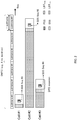
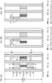
- FIG. 1B is a diagram to show examples of the locations of PSS/SSS radio resources included in DSs (DRSs) in LAA.
- FIG. 1B shows the DSs which three cells (cells #1 to #3) transmit respectively in the DMTC duration (for example, 6 ms).
- Cell #1 having judged on LBT idle in the first subframe of the DMTC duration, transmits a DS, which includes the PSS/SSS, for the DRS occasion, in this subframe.
- the DRS occasion is a period that is one subframe or less, this is by no means limiting, and the DRS occasion may be greater than one subframe.
- Cell #2 and cell #3 each show an example of DS transmission when there is an LBT busy period. These cells each transmit a DS, which includes the PSS/SSS, when LBT idle is rendered after the LBT busy period.
- the present inventors have come up with the idea that, when a DS (LAA DS) is received in a carrier in which LBT is configured, it may be possible to make the synchronization signals included in the DS have a different signal configuration than the SSS of existing systems, so that, based on this signal configuration, the index of the subframe in which the synchronization signals are received (and/or transmitted) can be specified.
- LAA DS LAA DS
- embodiments of the present invention can be configured so that a structure to make a licensed band (and the PCell) a carrier where listening (LBT) is not configured (which may also be referred to as a carrier where LBT is not executed, a carrier where LBT cannot be executed, and so on), and make an unlicensed band (and an SCell) a carrier where listening (LBT) is configured (which may also be referred to as a carrier where LBT is executed, a carrier where LBT should be executed, and so on) can be used in each embodiment.
- LBT listening
- the combination of carriers where LBT is not configured and carriers where LBT is configured, and PCells and Scells, is not limited to that given above.
- the present invention is applicable to the case where a UE connects with an unlicensed band (a carrier where listening (LBT) is configured) in stand-alone.
- the first embodiment of the present invention expands the SSS from the perspective of code resources (in a CDM (Code Division Multiplexing) manner).
- the LAA DS SSS is generated by using different scrambling sequences than existing SSSs.
- SSSs the SSSs of Rel. 8 to 12
- SSS scrambling sequence length is expanded, and the number of patterns that can be identified is expanded from 168 ⁇ 2 to a predetermined number (for example, 168 ⁇ 10), to allow linking with subframe indices (subframes #0 to #9).
- FIG. 2 is a diagram to explain the concept of the first embodiment.
- the diagram shown in FIG. 2 is the same as in FIG. 1B , except that, in each subframe, the SSS is constituted by a different sequence.
- the SSS of cell #1, transmitted in subframe #3 corresponds to sequences #3 (Seq #3).
- the SSSs of cells #2 and #3, transmitted in subframes #8 and #4, respectively correspond to sequences #8 and #4, respectively.
- FIGs. 3 provide diagram to show subcarriers where existing SSSs are mapped.
- FIG. 3A shows the SSS that is transmitted in subframe #0 (SSS 1 )
- FIG. 3B shows the SSS that is transmitted in subframe #5 (SSS 2 ).
- the sequence of each subcarrier is generated based on m 0 or m 1 , so that, when an SSS is received, a UE can judge whether its mapping shows SSS 1 or SSS 2 , and specify subframe #0 or #5.
- sequences having a length of 31, corresponding to m 0 and m 1 are arranged over 62 subcarriers, not including the subcarrier at the center of the band (DC (Direct Current) subcarrier), and, non-transmission subcarriers (guard subcarriers) that are five subcarriers wide are arranged at both ends of these.
- DC Direct Current
- guard subcarriers non-transmission subcarriers
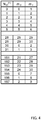
- FIG. 4 is a diagram to show the corresponding relationships among (m 0 , m 1 ) and N ID (1) in existing SSSs (mapping table).
- a s shown in FIG. 4 by representing m 0 and m 1 by using a sequence of a length of 31, N ID (1) can be represented in 168 patterns. Given that 31 C 2 >168, a sequence of a length of 31 is sufficient for N ID (1) .
- s 0 m 0 n , s 1 m 1 n , c 0 ( n ) , c 1 ( n ), z 0 m 0 n and z 1 m 1 n denote parameters that are given by modifying these parameters of existing SSSs taking into account the change of the sequence length from 31 to 42.
- the values of m 0 and m 1 and the subcarrier mapping of the SSS are determined based on the subframe in which the SSS is transmitted.
- FIGs. 5 provide diagrams to show subcarriers where SSSs according to the first embodiment are mapped.
- FIG. 5A shows the SSS (SSS 1 ) to be transmitted in subframes #0 to #4
- FIG. 5B shows the SSS (SSS 2 ) to be transmitted in subframes #5 to #9.
- the sequence of each subcarrier is generated based on m 0 or m 1 , so that so that, when an SSS is received, the UE can judge whether its mapping shows SSS 1 or SSS 2 , and specify the subframe among subframes #0 to #4 or subframes #5 to #9.
- sequences having a length of 42, corresponding to m 0 and m 1 are arranged over 84 subcarriers, not including the DC subcarrier, and, guard subcarriers that are six subcarriers wide are arranged at both ends of these.
- the SSS according to the first embodiment is transmitted in relatively the same symbol period as that used for existing SSSs.
- the SSS according to the first embodiment is transmitted in the symbol that is one symbol before the symbol in which the PSS is transmitted. Note that the symbol to transmit the SSS is by no means limited to this.
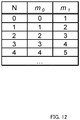
- FIG. 6 is a diagram to show examples of corresponding relationship between (m 0 , m 1 ), N ID (1) and N in the SSS according to the first embodiment (mapping table).
- a s shown in FIG. 6 by representing m 0 and m 1 by using 42 sequences, it is possible to provide N ID (1) in 168 patterns and provide N in five patterns. That is, the SSS of the first embodiment is generated by using sequences that are linked with SSS transmission timings. Note that, given that 42 C 2 >168 ⁇ 5, a sufficient number of sequences are provided to represent N while maintaining the functions of existing SSSs. Note that the linking of (m 0 , m 1 ), N ID (1) and N is by no means limited to what is shown in FIG. 6 .
- an SSS having an extended sequence length compared to existing SSSs is used as the SSS for the LAA DS, so that a UE can specify the indices of subframes where these SSSs are allocated, and establish frame timing synchronization. Also, since the LAA DS SSS can be arranged in the same central frequency and the same symbol period as those for an existing SSS, it is possible to reduce the increase of processing load pertaining to synchronization in the UE.
- a second embodiment of the present invention extends the SSS from the perspective of time and/or frequency resources (in TDM (Time Division Multiplexing) and/or FDM (Frequency Division Multiplexing) manner).
- TDM Time Division Multiplexing
- FDM Frequency Division Multiplexing
- a plurality of candidate time/frequency resources for transmitting the SSS are configured, and the subframe index where the SSS has been transmitted is identified based on the resource that has actually been used to transmit the SSS. That is, the candidate SSS resources are linked with SSS transmission timings (transmission subframes).
- the number of LAA DS SSS resource configurations is expanded from one to, for example, five, to allow linking with subframe indices (subframes #0 to #9).
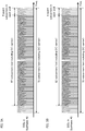
- FIG. 7 is a diagram to show examples of corresponding relationships among the subframe index, the scrambling sequence and the resource configuration according to the second embodiment.
- the SSS scrambling sequences correspond to the two sequences (Seq. #0 and #1) of existing SSSs, which have been described earlier with the first embodiment.
- the sequence indices to represent these sequences assume the values of, for example, 0 and 1.
- five patterns of candidate SSS resource configurations are provided (Cfg. #0 to #4), and correspond to varying radio resources.
- Cfg. #0 the same time/frequency resource configuration as for existing SSSs
- the SSSs of subframe #0 and subframe #5 can be configured to use the same sequences and RE (Resource Element) locations as those of existing SSSs.
- the resource configuration indices to indicate the resources where the SSSs are arranged can have the values of, for example, 0 to 4.
- the second embodiment is by no means limited to the corresponding relationships of FIG. 7 .
- One method (embodiment 2.1) of implementing the second embodiment of the present invention is to transmit the LAA DS SSS in one of a plurality of candidate resources that include candidate resources given by shifting an existing SSS in the frequency direction.
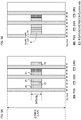
- FIGs. 8 provide diagrams to show examples of SSSs according to embodiment 2.1.
- FIG. 8A is a diagram to show examples of candidate SSS resources according to embodiment 2.1
- FIGs. 8B and 8C are diagrams, each showing an example of a DS that is transmitted in a DRS occasion.
- candidate resource configuration #0 represents the same resource as for an existing SSS.
- candidate resource configurations #1 to #4 represent resources that are given by candidate resource configuration #0 in the frequency direction. Note that the arrangement and order of candidate resource configurations #0 to #4 are by no means limited to the examples of FIG. 8A . In this way, according to embodiment 2.1, it is preferable to configure a plurality of candidate resources in a symbol (symbol #5 of the first slot in a subframe) having the same symbol index as one for an existing SSS, this is by no means limiting.
- a predetermined candidate resource so that part of the subcarriers, including the guard carriers, overlaps at least one different candidate resource.
- each candidate resource is constituted by 62 subcarriers where the sequence is actually arranged. Note that, in other embodiments, too, the SSS frequency resource with may be determined like this.
- FIGs. 8 show examples in which CRSs are transmitted in symbol #4 of the first slot and symbol #0 of the second slot. Also, the transmission of the DS starts from a symbol other than symbol #0. However, this signal configuration is by no means limiting.
- the LAA DS SSS is transmitted in one of a plurality of candidate resources, so that a UE can specify the index of the subframe where the SSS is allocated, and establish frame timing synchronization. Also, since the LAA DS SSS can be arranged in the same symbol period as one for an existing SSS, it is possible to reduce the expansion of DRS occasions.
- the LAA DS SSS is transmitted using one of a plurality of candidate resources including candidate resources that are given by shifting an existing SSS in the time direction.
- FIGs. 9 provide diagrams to show examples of SSSs according to embodiment 2.2.
- FIG. 9A is a diagram to show examples of candidate SSS resources according to embodiment 2.2
- FIG. 9B is a diagram to show an example of a DS that is transmitted in a DRS occasion.
- candidate resource configuration #0 represents the same resource as one for an existing SSS.
- candidate resource configurations #1 to #4 represent resources that are given by candidate resource configuration #0 in the frequency direction. For example, a plurality of candidate resources may be mapped to symbols #1, #2, #3 and #5 of the first slot in a subframe and to symbol #1 of the second slot. Note that the arrangement and order of candidate resource configurations #0 to #4 are by no means limited to the examples of FIG. 9A . In this way, according to embodiment 2.2, it is preferable to configure a plurality of candidate resources in the same subcarriers (frequency locations) as ones for an existing SSS, this is by no means limiting.
- the SSS can be transmitted using one of a plurality of time resources (symbols) in a DRS occasion, if there is a symbol in which the SSS is not transmitted and in which an eNB transmits nothing, then there is a possibility that another system's LBT succeeds. In this case, the right to use the channel is taken away, and there is a threat that the eNB is unable to transmit the SSS, and the UE takes a longer time to establish synchronization becomes longer, fails RRM measurements, and so on.
- time resources symbolsymbols
- reference signals such as the cell-specific reference signal (CRS), the channel state information reference signal (CSI-RS), the demodulation reference signal (DMRS) and so on
- a downlink shared channel (Physical Downlink Shared Channel)
- a downlink L1/L2 control channel for example, the EPDCCH (Enhanced Physical Downlink Control Channel)
- MIBs Master Information Blocks
- SIBs System Information Block
- FIGs. 9 show examples in which CRSs are transmitted in symbol #0 and symbol #4 of the first slot and symbol #0 of the second slot. Also, the transmission of the DS is started from symbol #0. However, this signal configuration is by no means limiting.
- the LAA DS SSS is transmitted in one of a plurality of candidate resources, so that a UE can specify the index of the subframe where the SSS is allocated, and establish frame timing synchronization. Also, since the LAA DS SSS can be arranged in a frequency resource that is less than six PRBs, it is possible to reduce the increase of processing load pertaining to synchronization in the UE.
- the LAA DS SSS is transmitted using one of a plurality of candidate resources including candidate resources that are given by shifting an existing SSS in the time and/or frequency directions.
- the PSS may be transmitted in different radio resources than the existing PSS.
- FIGs. 10 provide diagrams to show examples of SSSs according to embodiment 2.3.
- FIG. 10A is a diagram to show examples of candidate SSS resources according to embodiment 2.3
- FIG. 10B and FIG. 10C are diagrams to show an example of a DS that is transmitted in a DRS occasion.
- a PSS for candidate SSS resource configuration #0 and a PSS for candidate SSS resource configurations #1 to #4 are set forth.
- Candidate SSS resource configuration #0 is the same resource (six PRBs and symbol #5) as one for an existing SSS
- the PSS for this configuration #0 is the same resource (six PRBs and symbol #6) as that of the existing PSS. It is thus preferable, with embodiment 2.3, to configure one candidate resource in the same resource as one for an existing SSS, but this is by no means limiting.
- candidate SSS resource configurations #1 to #4 are transmitted in the same subcarrier location as that of the existing PSS, but in a different symbol (symbol #3). Furthermore, candidate SSS resource configurations #1 to #4 represent resources that are each given by shifting candidate resource configuration #0 in the time and frequency directions.
- each candidate SSS resource it is preferable to place each candidate SSS resource as close as possible to the relative location of either PSS.
- a plurality of candidate resources may be mapped to symbols #1 and #3 of the first slot in a subframe, to be as close as possible to the PSS for configuration #1 to #4 (so that, for example, the PSS and at least part of the frequency and/or time resource adjoin each other).
- the arrangement and/or the order of candidate resource configurations #0 to #4 and the PSS resources are by no means limited to the examples of FIG. 10A .
- an eNB it is preferable to control an eNB to transmit predetermined signals in candidate resources (symbols) in which the eNB does not transmit the SSS. Also, it is equally possible to control the eNB to transmit predetermined signals in time resources (symbols) in which the eNB does not transmit either PSS.
- FIGs. 10 show examples in which CRSs are transmitted in symbol #4 of the first slot and symbol #0 of the second slot. Also, the transmission of the DS is started from symbol #0. However, this signal configuration is by no means limiting.
- the SSS may be transmitted in the same time resource (symbol) as that of the PSS.
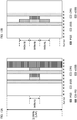
- FIGs. 11 provide diagrams to show other examples of SSSs according to embodiment 2.3.
- FIG. 11A is a diagram to show examples of candidate SSS resources according to embodiment 2.3
- FIG. 11B is a diagram to show an example of a DS that is transmitted in a DRS occasion.
- candidate SSS resource configuration #0 is the same resource (six PRBs and symbol #5) as one for an existing SSS
- the PSS is the same resource (six PRBs and symbol #6) as one for the existing PSS.
- candidate resource configuration #1 and #2 are resources that are given by shifting an existing SSS in the frequency direction.
- candidate resource configuration #3 and #4 are resources that adjoin the PSS in the frequency domain in the same symbol as one for the existing PSS. Note that the arrangement and/or the order of candidate resource configurations #0 to #4 and the PSS resources are by no means limited to the examples of FIG. 11A .
- FIGs. 11 show examples in which CRSs are transmitted in symbol #4 of the first slot and symbol #0 of the second slot. Also, the transmission of the DS is started from symbol #2. However, this signal configuration is by no means limiting.
- the LAA DS SSS is transmitted in one of a plurality of candidate resources, so that a UE can specify the index of the subframe where the SSS is allocated, and establish frame timing synchronization. Also, by employing a configuration to transmit the PSS in different symbols than the existing PSS, it is possible to prevent signals from being transmitted between the SSS and the PSS, and leading to failure of DS transmission (and DS-based synchronization/RRM measurements). Also, by employing a configuration to transmit the SSS in the same symbol as one for the existing PSS, it is possible to reduce the expansion of DRS occasions.
- another signal that is for use for specifying the subframe index of an existing SSS is transmitted.
- the configurations of the existing PSS/SSS are maintained as-is, and a UE judges the subframe index based on this another signal and the SSS.
- this new signal may be referred to as a synchronization signal, and also referred to as, for example, an "eSSS” (enhanced SSS), an "additional SSS,” a "new SSS,” an "LAA SSS,” a “DRS SSS,” a "DS SSS,” the "Rel. 13 SSS,” and so on. Note that these names may be applied to the SSS of the first embodiment and/or the SSS of the second embodiment.
- the eSSS may be generated based on the same or a similar sequence generation method as for existing SSSs, as long as the eSSS is a signal that can be used to specify variable N, which represents the candidate subframe index, in equation 3.
- subframe index M may be referred to as the subframe index where the LAA DS eSSS is transmitted.
- FIG. 12 is a diagram to show examples of corresponding relationship among (m 0 , m 1 ) and N in the eSSS according to the third embodiment (mapping table).
- the eSSS may be generated by using, for example, sequences having a sequence length of 4, as long as N can be represented in five patterns. Note that, the linking of (m 0 , m 1 ) and N is not limited what is shown in FIG. 12 . Also, information other than N may be linked with the eSSS sequence and/or resource (frequency/time resource).
- FIGs. 13 provide diagrams to show examples of eSSSs according to the third embodiment.
- FIG. 13A is a diagram to show an example in which an eSSS is mapped to a blank symbol (symbol in which no other signals are transmitted).
- an eSSS is mapped to symbol #1 of the second slot in a subframe.
- FIG. 13B is a diagram to show an example in which eSSSs are mapped to blank REs (for example, REs in a symbol in which other signals (for example, an SSS) are transmitted).
- REs for example, REs in a symbol in which other signals (for example, an SSS) are transmitted.
- an eSSS is mapped to either frequency portion adjoining the SSS.
- FIG. 13A shows examples in which CRSs are transmitted in symbol #4 of the first slot and symbol #0 of the second slot. Also, the transmission of the DS is started from symbol #0. Furthermore, FIG. 13A shows an example in which the CSI-RS is transmitted after symbol #0, in the second slot of a subframe.
- this signal configuration is by no means limiting.
- the LAA DS of the third embodiment may be configured to include at least a PSS, an SSS, an eSSS and a CRS, and may be configured to include, furthermore, a CSI-RS.
- an eSSS is transmitted in order to specify the subframe index of the LAA DS SSS, so that a UE can specify the subframe index where the SSS is allocated, and establish frame timing synchronization.
- Each embodiment that has been described above may be used when, for example, a PCell and an SCell are not synchronized (for example, when the distance from a UE to a radio base station forming an unlicensed band SCell is different from the distance from the UE to a radio base station forming a licensed band PCell).
- an SSS that is received in an LAA SCell can be ignored. That is, in an LAA SCell, the subframe index in which the SSS of this cell is transmitted does not have to be derived based on this SCell's signals.
- a configuration to acquire the above subframe index by detecting the PSS/SSS in the PCell may be employed.
- a cell list (for example, a list of cell IDs) may be reported so as to know whether or not an SCell which the user terminal detects is a cell that is synchronized with the connecting PCell.
- information about the sequence of the LAA DS SSS and/or eSSS, subcarrier mapping of the SSS and/or eSSS, the frequency/time resource (candidate resources) of the SSS and/or eSSS, the corresponding relationship between the SSS and/or eSSS with the subframe index and so on may be reported to UEs by using one of higher layer signaling (for example, RRC (Radio Resource Control) signaling, broadcast information (MIBs and SIBs) and so on) and downlink control information (DCI), or by using a combination of these.
- RRC Radio Resource Control
- radio communication methods of the above-described embodiments may be applied individually or may be applied in combination.
- the structure of the radio communication system according to an embodiment of the present invention will be described below.
- the radio communication method according to one and/or a combination of the above-described embodiments of the present invention is employed.
- FIG. 14 is a diagram to show an example of a schematic structure of a radio communication system according to an embodiment of the present invention.
- the radio communication system 1 can adopt carrier aggregation (CA) and/or adopt dual connectivity (DC) to group a plurality of fundamental frequency blocks (component carriers) into one, where the LTE system bandwidth constitutes one unit.
- the radio communication system 1 has a radio base station (for example, an LTE-U base station) that is capable of using unlicensed bands.
- radio communication system 1 may be referred to as "SUPER 3G,” “LTE-A,” (LTE-Advanced), “IMT-Advanced,” “4G” (4th generation mobile communication system), “5G” (5th generation mobile communication system), “FRA” (Future Radio Access) and so on.
- the radio communication system 1 shown in FIG. 8 includes a radio base station 11 that forms a macro cell C1, and radio base stations 12 (12a to 12c) that form small cells C2, which are placed within the macro cell C1 and which are narrower than the macro cell C1. Also, user terminals 20 are placed in the macro cell C1 and in each small cell C2. For example, a mode may be possible in which the macro cell C1 is used in a licensed band and the small cells C2 are used in unlicensed bands (LTE-U). Also, a mode may be also possible in which part of the small cells is used in a licensed band and the rest of the small cells are used in unlicensed bands.
- LTE-U unlicensed bands
- the user terminals 20 can connect with both the radio base station 11 and the radio base stations 12.
- the user terminals 20 may use the macro cell C1 and the small cells C2, which use different frequencies, at the same time, by means of CA or DC.
- assist information for example, the DL signal configuration
- a radio base station 12 which is, for example, an LTE-U base station
- a structure may be employed in which, when CA is used between the licensed band and the unlicensed band, one of the radio base stations (for example, the radio base station 11) controls the scheduling of the licensed band cells and the unlicensed band cells.
- a carrier of a relatively low frequency band for example, 2 GHz
- a narrow bandwidth referred to as, for example, an "existing carrier,” a “legacy carrier” and so on.
- a carrier of a relatively high frequency band for example, 3.5 GHz, 5 GHz and so on
- a wide bandwidth may be used, or the same carrier as that used in the radio base station 11 may be used.
- the configuration of the frequency band for use in each radio base station is by no means limited to these.
- a structure may be employed here in which wire connection (for example, means in compliance with the CPRI (Common Public Radio Interface) such as optical fiber, the X2 interface and so on) or wireless connection is established between the radio base station 11 and the radio base station 12 (or between two radio base stations 12).
- wire connection for example, means in compliance with the CPRI (Common Public Radio Interface) such as optical fiber, the X2 interface and so on
- wireless connection is established between the radio base station 11 and the radio base station 12 (or between two radio base stations 12).
- the radio base station 11 and the radio base stations 12 are each connected with a higher station apparatus 30, and are connected with a core network 40 via the higher station apparatus 30.
- the higher station apparatus 30 may be, for example, an access gateway apparatus, a radio network controller (RNC), a mobility management entity (MME) and so on, but is by no means limited to these.
- RNC radio network controller
- MME mobility management entity
- each radio base station 12 may be connected with the higher station apparatus 30 via the radio base station 11.
- the radio base station 11 is a radio base station having a relatively wide coverage, and may be referred to as a "macro base station,” a “central node,” an “eNB” (eNodeB), a “transmitting/receiving point” and so on.
- the radio base stations 12 are radio base stations having local coverages, and may be referred to as "small base stations,” “micro base stations,” “pico base stations,” “femto base stations,” “HeNBs” (Home eNodeBs), “RRHs” (Remote Radio Heads), “transmitting/receiving points” and so on.
- the radio base stations 11 and 12 will be collectively referred to as “radio base stations 10," unless specified otherwise.
- the user terminals 20 are terminals to support various communication schemes such as LTE, LTE-A and so on, and may be either mobile communication terminals or stationary communication terminals.
- OFDMA Orthogonal Frequency Division Multiple Access
- SC-FDMA Single-Carrier Frequency Division Multiple Access
- OFDMA is a multi-carrier communication scheme to perform communication by dividing a frequency band into a plurality of narrow frequency bands (subcarriers) and mapping data to each subcarrier.
- SC-FDMA is a single-carrier communication scheme to mitigate interference between terminals by dividing the system band into bands formed with one or continuous resource blocks per terminal, and allowing a plurality of terminals to use mutually different bands. Note that the uplink and downlink radio access schemes are by no means limited to the combination of these.
- a downlink shared channel (PDSCH: Physical Downlink Shared CHannel), which is used by each user terminal 20 on a shared basis, a broadcast channel (PBCH: Physical Broadcast CHannel), downlink L1/L2 control channels and so on are used as downlink channels.
- PDSCH Physical Downlink Shared CHannel
- PBCH Physical Broadcast CHannel
- SIBs System Information Blocks
- MIBs Master Information Blocks
- the downlink L1/L2 control channels include a PDCCH (Physical Downlink Control CHannel), an EPDCCH (Enhanced Physical Downlink Control CHannel), a PCFICH (Physical Control Format Indicator CHannel), a PHICH (Physical Hybrid-ARQ Indicator CHannel) and so on.
- Downlink control information (DCI) including PDSCH and PUSCH scheduling information is communicated by the PDCCH.
- the number of OFDM symbols to use for the PDCCH is communicated by the PCFICH.
- HARQ delivery acknowledgement signals (ACKs/NACKs) in response to the PUSCH are communicated by the PHICH.
- the EPDCCH is frequency-division-multiplexed with the PDSCH and used to communicate DCI and so on, like the PDCCH.
- an uplink shared channel (PUSCH: Physical Uplink Shared CHannel), which is used by each user terminal 20 on a shared basis, an uplink control channel (PUCCH: Physical Uplink Control CHannel), a random access channel (PRACH: Physical Random Access CHannel) and so on are used as uplink channels.
- the PUSCH may be referred to as an uplink data channel.
- User data and higher layer control information are communicated by the PUSCH.
- downlink radio quality information (CQI: Channel Quality Indicator), delivery acknowledgment information (ACKs/NACKs) and so on are communicated by the PUCCH.
- CQI Channel Quality Indicator
- ACKs/NACKs delivery acknowledgment information
- PRACH random access preambles for establishing connections with cells are communicated.
- CRSs cell-specific reference signals
- CSI-RSs channel state information reference signals
- DMRSs demodulation reference signal
- SRSs Sounding Reference Signals
- DMRSs demodulation reference signals
- uplink reference signals the DMRSs may be referred to as user terminal-specific reference signals (UE-specific Reference Signals).
- UE-specific Reference Signals the reference signals to be communicated are by no means limited to these.
- FIG. 15 is a diagram to show an example of an overall structure of a radio base station according to an embodiment of the present invention.
- a radio base station 10 has a plurality of transmitting/receiving antennas 101, amplifying sections 102, transmitting/receiving sections 103, a baseband signal processing section 104, a call processing section 105 and a communication path interface 106. Note that one or more transmitting/receiving antennas 101, amplifying sections 102 and transmitting/receiving sections 103 may be provided.
- User data to be transmitted from the radio base station 10 to a user terminal 20 on the downlink is input from the higher station apparatus 30 to the baseband signal processing section 104, via the communication path interface 106.
- the user data is subjected to a PDCP (Packet Data Convergence Protocol) layer process, user data division and coupling, RLC (Radio Link Control) layer transmission processes such as RLC retransmission control, MAC (Medium Access Control) retransmission control (for example, an HARQ (Hybrid Automatic Repeat reQuest) transmission process), scheduling, transport format selection, channel coding, an inverse fast Fourier transform (IFFT) process and a precoding process, and the result is forwarded to each transmitting/receiving section 103.
- PDCP Packet Data Convergence Protocol
- RLC Radio Link Control
- MAC Medium Access Control
- HARQ Hybrid Automatic Repeat reQuest
- IFFT inverse fast Fourier transform
- precoding forwarded to each transmitting/receiving section 103.
- downlink control signals are also subjected to transmission processes such as channel coding and an inverse fast Fourier transform, and forwarded to each transmitting/receiving section 103.
- Baseband signals that are pre-coded and output from the baseband signal processing section 104 on a per antenna basis are converted into a radio frequency band in the transmitting/receiving sections 103, and then transmitted.
- the radio frequency signals subjected to frequency conversion in the transmitting/receiving sections 103 are amplified in the amplifying sections 102, and transmitted from the transmitting/receiving antennas 101.
- the transmitting/receiving sections 103 are capable of transmitting/receiving UL/DL signals in unlicensed bands. Note that the transmitting/receiving sections 103 may be capable of transmitting/receiving UL/DL signals in licensed bands as well.
- the transmitting/receiving sections 103 can be constituted by transmitters/receivers, transmitting/receiving circuits or transmitting/receiving devices that can be described based on common understanding of the technical field to which the present invention pertains. Note that a transmitting/receiving section 103 may be structured as a transmitting/receiving section in one entity, or may be constituted by a transmitting section and a receiving section.
- radio frequency signals that are received in the transmitting/receiving antennas 101 are each amplified in the amplifying sections 102.
- the transmitting/receiving sections 103 receive the uplink signals amplified in the amplifying sections 102.
- the received signals are converted into the baseband signal through frequency conversion in the transmitting/receiving sections 103 and output to the baseband signal processing section 104.
- the baseband signal processing section 104 user data that is included in the uplink signals that are input is subjected to a fast Fourier transform (FFT) process, an inverse discrete Fourier transform (IDFT) process, error correction decoding, a MAC retransmission control receiving process, and RLC layer and PDCP layer receiving processes, and forwarded to the higher station apparatus 30 via the communication path interface 106.
- the call processing section 105 performs call processing such as setting up and releasing communication channels, manages the state of the radio base station 10 and manages the radio resources.
- the communication path interface section 106 transmits and receives signals to and from the higher station apparatus 30 via a predetermined interface. Also, the communication path interface 106 may transmit and receive signals (backhaul signaling) with other radio base stations 10 via an inter-base station interface (for example, an interface in compliance with the CPRI (Common Public Radio Interface)m such as optical fiber, the X2 interface).
- an inter-base station interface for example, an interface in compliance with the CPRI (Common Public Radio Interface)m such as optical fiber, the X2 interface.
- the transmitting/receiving sections 103 transmit downlink signals to the user terminal 20 by using at least an unlicensed band.
- the transmitting/receiving sections 103 transmit a DS, which includes an SSS that is different from an existing SSS, to the user terminals 20, in an unlicensed band, in a DMTC duration that is configured in the user terminals 20.
- the transmitting/receiving sections 103 may transmit the existing PSS/SSS in a licensed band and/or an unlicensed band.
- the transmitting/receiving sections 103 receive uplink signals from the user terminals 20 by at least using an unlicensed band.
- the transmitting/receiving sections 103 may receive DS RRM measurement results (for example, CSI feedback and/or the like), from the user terminals 20, in a licensed band and/or an unlicensed band.
- FIG. 16 is a diagram to show an example of a functional structure of a radio base station according to one embodiment of the present invention. Note that, although FIG. 10 primarily shows functional blocks that pertain to characteristic parts of the present embodiment, the radio base station 10 has other functional blocks that are necessary for radio communication as well. As shown in FIG. 16 , the baseband signal processing section 104 has a control section (scheduler) 301, a transmission signal generating section (generating section) 302, a mapping section 303, a received signal processing section 304 and a measurement section 305.
- the baseband signal processing section 104 has a control section (scheduler) 301, a transmission signal generating section (generating section) 302, a mapping section 303, a received signal processing section 304 and a measurement section 305.
- the control section (scheduler) 301 controls the whole of the radio base station 10. Note that, when a licensed band and an unlicensed band are scheduled with one control section (scheduler) 301, the control section 301 controls communication in the licensed band cells and the unlicensed band cells.
- a controller, a control circuit or a control device that can be described based on common understanding of the technical field to which the present invention pertains can be used.
- the control section 301 controls the generation of signals in the transmission signal generating section 302, the allocation of signals by the mapping section 303, and so on. Furthermore, the control section 301 controls the signal receiving processes in the received signal processing section 304, the measurements of signals in the measurement section 305, and so on.
- the control section 301 controls the scheduling (for example, resource allocation) of downlink data signals that are transmitted in the PDSCH and downlink control signals that are communicated in the PDCCH and/or the EPDCCH. Also, the control section 301 controls the scheduling of downlink reference signals such as synchronization signals (the PSS (Primary Synchronization Signal) and the SSS (Secondary Synchronization Signal)), the CRS, the CSI-RS, the DM-RS and so on.
- synchronization signals the PSS (Primary Synchronization Signal) and the SSS (Secondary Synchronization Signal)
- the CRS the CSI-RS
- DM-RS Downlink Reference Signal
- control section 301 controls the scheduling of uplink data signals transmitted in the PUSCH, uplink control signals transmitted in the PUCCH and/or the PUSCH (for example, delivery acknowledgement signals (HARQ-ACKs)), random access preambles transmitted in the PRACH, uplink reference signals and so on.
- uplink control signals transmitted in the PUCCH and/or the PUSCH for example, delivery acknowledgement signals (HARQ-ACKs)
- HARQ-ACKs delivery acknowledgement signals
- random access preambles transmitted in the PRACH uplink reference signals and so on.
- the control section 301 controls the transmission of downlink signals in the transmission signal generating section 302 and the mapping section 303 in accordance with the results of LBT acquired in the measurement section 305.
- the control section 301 controls the generation, mapping and transmission of this synchronization signals.
- the control section 301 controls the DS so that a synchronization signal that is different from an existing SSS (SSS and/or eSSS) is included in the DS.
- the control section 301 generates this synchronization signal in association with a subframe index.
- the control section 301 may exert control so that the SSS to be included in the DS is generated by using a sequence (for example, a 42-length sequences) that is associated with the transmission timing of this SSS and that is different from one for an existing SSS (first embodiment).
- control section 301 may exert control so that the SSS to be included in the DS is mapped to and transmitted in one of candidate resources that include resources that are different from ones for an existing SSS (second embodiment). Also, the control section 301 may control the PSS to be included in the DS to be mapped to and transmitted in a resource that is different from one for the existing PSS.
- control section 301 may include and transmit another signal (for example, an eSSS) that is for use for specifying the subframe index of an existing SSS, in the DS (third embodiment). Also, the control section 301 may control the PSS to be included in the DS to be mapped to and transmitted in a resource that is different from one for the existing PSS.
- another signal for example, an eSSS
- eSSS eSSS
- the control section 301 may control the PSS to be included in the DS to be mapped to and transmitted in a resource that is different from one for the existing PSS.
- the transmission signal generating section 302 generates downlink signals (downlink control signals, downlink data signals, downlink reference signals and so on) based on commands from the control section 301, and outputs these signals to the mapping section 303.
- the transmission signal generating section 302 can be constituted by a signal generator, a signal generating circuit or a signal generating device that can be described based on common understanding of the technical field to which the present invention pertains.
- the transmission signal generating section 302 generates DL assignments, which report downlink signal allocation information, and UL grants, which report uplink signal allocation information, based on commands from the control section 301. Also, the downlink data signals are subjected to the coding process, the modulation process and so on, by using coding rates and modulation schemes that are determined based on, for example, channel state information (CSI: Channel State Information) reported from each user terminal. Also, the transmission signal generating section 302 generates a DS that includes a PSS and an SSS (and/or an eSSS).
- CSI Channel State Information
- the mapping section 303 maps the downlink signals generated in the transmission signal generating section 302 to predetermined radio resources based on commands from the control section 301, and outputs these to the transmitting/receiving sections 103.
- the mapping section 303 can be constituted by a mapper, a mapping circuit or a mapping device that can be described based on common understanding of the technical field to which the present invention pertains.
- the received signal processing section 304 performs receiving processes (for example, demapping, demodulation, decoding and so on) of received signals that are input from the transmitting/receiving sections 103.
- the received signals include, for example, uplink signals transmitted from the user terminals 20 (uplink control signals, uplink data signals, uplink reference signals and so on).
- the received signal processing section 304 can be constituted by a signal processor, a signal processing circuit or a signal processing device that can be described based on common understanding of the technical field to which the present invention pertains.
- the received signal processing section 304 outputs the decoded information acquired through the receiving processes to the control section 301. For example, when a PUCCH to contain an HARQ-ACK is received, the received signal processing section 304 outputs this HARQ-ACK to the control section 301. Also, the received signal processing section 304 outputs the received signals, the signals after the receiving processes and so on, to the measurement section 305.
- the measurement section 305 conducts measurements with respect to the received signals.
- the measurement section 305 can be constituted by a measurer, a measurement circuit or a measurement device that can be described based on common understanding of the technical field to which the present invention pertains.
- the measurement section 305 executes LBT in a carrier where LBT is configured (for example, an unlicensed band) based on commands from the control section 301, and outputs the results of LBT (for example, judgments as to whether the channel state is idle or busy) to the control section 301.
- LBT is configured (for example, an unlicensed band) based on commands from the control section 301, and outputs the results of LBT (for example, judgments as to whether the channel state is idle or busy) to the control section 301.
- the received signal processing section 404 may measure the received power (for example, the RSRP (Reference Signal Received Power)), the received quality (RSRQ (Reference Signal Received Quality)), channel states and so on. The measurement results may be output to the control section 301.
- the RSRP Reference Signal Received Power
- RSS Reference Signal Received Quality
- FIG. 17 is a diagram to show an example of an overall structure of a user terminal according to an embodiment of the present invention.
- a user terminal 20 has a plurality of transmitting/receiving antennas 201, amplifying sections 202, transmitting/receiving sections 203, a baseband signal processing section 204 and an application section 205. Note that one or more transmitting/receiving antennas 201, amplifying sections 202 and transmitting/receiving sections 203 may be provided.
- Radio frequency signals that are received in a plurality of transmitting/receiving antennas 201 are each amplified in the amplifying sections 202.
- Each transmitting/receiving section 203 receives the downlink signals amplified in the amplifying sections 202.
- the received signals are subjected to frequency conversion and converted into the baseband signal in the transmitting/receiving sections 203, and output to the baseband signal processing section 204.
- the transmitting/receiving sections 203 are capable of transmitting/receiving UL/DL signals in unlicensed bands. Note that the transmitting/receiving sections 203 may be capable of transmitting/receiving UL/DL signals in licensed bands as well.
- the transmitting/receiving sections 203 can be constituted by transmitters/receivers, transmitting/receiving circuits or transmitting/receiving devices that can be described based on common understanding of the technical field to which the present invention pertains. Note that a transmitting/receiving section 203 may be structured as a transmitting/receiving section in one entity, or may be constituted by a transmitting section and a receiving section.
- the baseband signal that is input is subjected to an FFT process, error correction decoding, a retransmission control receiving process, and so on.
- Downlink user data is forwarded to the application section 205.
- the application section 205 performs processes related to higher layers above the physical layer and the MAC layer, and so on. Furthermore, in the downlink data, broadcast information is also forwarded to the application section 205.
- uplink user data is input from the application section 205 to the baseband signal processing section 204.
- the baseband signal processing section 204 performs a retransmission control transmission process (for example, an HARQ transmission process), channel coding, pre-coding, a discrete Fourier transform (DFT) process, an IFFT process and so on, and the result is forwarded to each transmitting/receiving section 203.
- the baseband signal that is output from the baseband signal processing section 204 is converted into a radio frequency band in the transmitting/receiving sections 203.
- the radio frequency signals that are subjected to frequency conversion in the transmitting/receiving sections 203 are amplified in the amplifying sections 202, and transmitted from the transmitting/receiving antennas 201.
- the transmitting/receiving sections 203 receive downlink signals transmitted from the radio base station 10, by using at least an unlicensed band.
- the transmitting/receiving sections 203 receive a DS, which includes an SSS that is different from an existing SSS, in an unlicensed band, in a DMTC duration that is configured by the radio base station 10.
- the transmitting/receiving sections 203 may receive the existing PSS/SSS in a licensed band and/or an unlicensed band.
- the transmitting/receiving sections 203 transmit uplink signals to the radio base station 10 by at least using an unlicensed band.
- the transmitting/receiving sections 203 may transmit DS RRM measurement results (for example, CSI feedback and/or the like) in a licensed band and/or an unlicensed band.
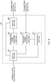
- FIG. 18 is a diagram to show an example of a functional structure of a user terminal according to one embodiment of the present invention. Note that, although FIG. 18 primarily shows functional blocks that pertain to characteristic parts of the present embodiment, the user terminal 20 has other functional blocks that are necessary for radio communication as well. As shown in FIG. 18 , the baseband signal processing section 204 provided in the user terminal 20 at least has a control section 401, a transmission signal generating section 402, a mapping section 403, a received signal processing section 404 and a measurement section 405.
- the control section 401 controls the whole of the user terminal 20.
- the control section 401 can be constituted by a controller, a control circuit or a control device that can be described based on common understanding of the technical field to which the present invention pertains.
- the control section 401 controls the generation of signals in the transmission signal generating section 402, the allocation of signals by the mapping section 403, and so on. Furthermore, the control section 401 controls the signal receiving processes in the received signal processing section 404, the measurements of signals in the measurement section 405, and so on.
- the control section 401 acquires the downlink control signals (signals transmitted in the PDCCH/EPDCCH) and downlink data signals (signals transmitted in the PDSCH) transmitted from the radio base station 10, from the received signal processing section 404.
- the control section 401 controls the generation of uplink control signals (for example, delivery acknowledgement signals (HARQ-ACKs) and so on) and uplink data signals based on the downlink control signals, the results of deciding whether or not retransmission control is necessary for the downlink data signals, and so on.
- uplink control signals for example, delivery acknowledgement signals (HARQ-ACKs) and so on
- the control section 401 controls the transmission of uplink signals in the transmission signal generating section 402 and the mapping section 403 in accordance with the results of LBT acquired in the measurement section 305. Also, the control section 401 controls the received signal processing section 404 and the measurement section 405 to perform RRM measurement, cell search and so on, in unlicensed bands, using the DS (LAA DS).
- LAA DS DS
- control section 401 may exert control so that, based on a signal (SSS and/or eSSS) that is different from an existing SSS, the index of the subframe in which the DS is received (and/or in which the signal is received) is specified. Also, the control section 401 may exert control so that the index of the subframe index in which the SSS of the DS is received is acquired by detecting the PSS/SSS in the PCell.
- a signal SSS and/or eSSS
- control section 401 may exert control so that the received power, the received quality and/or the channel states, measured in the measurement section 405 by using the reference signals (for example, the CRS, the CSI-RS and so on) included in the LAA DS, are acquired, and, based on these, feedback information (for example, CSI) is generated and transmitted to the radio base station 10.
- the reference signals for example, the CRS, the CSI-RS and so on
- feedback information for example, CSI
- the transmission signal generating section 402 generates uplink signals (uplink control signals, uplink data signals, uplink reference signals and so on) based on commands from the control section 401, and outputs these signals to the mapping section 403.
- the transmission signal generating section 402 can be constituted by a signal generator, a signal generating circuit or a signal generating device that can be described based on common understanding of the technical field to which the present invention pertains.
- the transmission signal generating section 402 generates uplink control signals such as delivery acknowledgement signals (HARQ-ACKs), channel state information (CSI) and so on, based on commands from the control section 401. Also, the transmission signal generating section 402 generates uplink data signals based on commands from the control section 401. For example, when a UL grant is included in a downlink control signal that is reported from the radio base station 10, the control section 401 commands the transmission signal generating section 402 to generate an uplink data signal.
- uplink control signals such as delivery acknowledgement signals (HARQ-ACKs), channel state information (CSI) and so on
- CSI channel state information
- the mapping section 403 maps the uplink signals generated in the transmission signal generating section 402 to radio resources based on commands from the control section 401, and output the result to the transmitting/receiving sections 203.
- the mapping section 403 can be constituted by a mapper, a mapping circuit or a mapping device that can be described based on common understanding of the technical field to which the present invention pertains.
- the received signal processing section 404 performs receiving processes (for example, demapping, demodulation, decoding and so on) of received signals that are input from the transmitting/receiving sections 203.
- the received signals include, for example, downlink signals (downlink control signals, downlink data signals, downlink reference signals and so on) that are transmitted from the radio base station 10.
- the received signal processing section 404 can be constituted by a signal processor, a signal processing circuit or a signal processing device that can be described based on common understanding of the technical field to which the present invention pertains. Also, the received signal processing section 404 can constitute the receiving section according to the present invention.
- the received signal processing section 404 output the decoded information that is acquired through the receiving processes to the control section 401.
- the received signal processing section 404 outputs, for example, broadcast information, system information, RRC signaling, DCI and so on, to the control section 401. Also, the received signal processing section 404 outputs the received signals, the signals after the receiving processes and so on to the measurement section 405.
- the measurement section 405 conducts measurements with respect to the received signals.
- the measurement section 405 can be constituted by a measurer, a measurement circuit or a measurement device that can be described based on common understanding of the technical field to which the present invention pertains.
- the measurement section 405 executes LBT in a carrier where LBT is configured (for example, an unlicensed band) based on commands from the control section 401, and outputs the results of LBT (for example, judgments as to whether the channel state is idle or busy) to the control section 401.
- LBT is configured (for example, an unlicensed band) based on commands from the control section 401, and outputs the results of LBT (for example, judgments as to whether the channel state is idle or busy) to the control section 401.
- the measurement section 405 may measure the received power (for example, RSRP), the received quality (for example, RSRQ), the channel states and so on of the received signals. For example, the measurement section performs RRM measurements of the LAA DS. The measurement results may be output to the control section 401.
- each functional block may be implemented in arbitrary combinations of hardware and software.
- the means for implementing each functional block is not particularly limited. That is, each functional block may be implemented with one physically-integrated device, or may be implemented by connecting two physically-separate devices via radio or wire and using these multiple devices.
- radio base stations 10 and user terminals 20 may be implemented using hardware such as ASICs (Application-Specific Integrated Circuits), PLDs (Programmable Logic Devices), FPGAs (Field Programmable Gate Arrays), and so on.
- the radio base stations 10 and user terminals 20 may be implemented with a computer device that includes a processor (CPU), a communication interface for connecting with networks, a memory and a computer-readable storage medium that holds programs. That is, radio base stations and user terminals according to an embodiment of the present invention may function as computers that execute the processes of the radio communication method of the present invention.
- the processor and the memory are connected with a bus for communicating information.
- the computer-readable recording medium is a storage medium such as, for example, a flexible disk, an opto-magnetic disk, a ROM, an EPROM, a CD-ROM, a RAM, a hard disk and so on.
- the programs may be transmitted from the network through, for example, electric communication channels.
- the radio base stations 10 and user terminals 20 may include input devices such as input keys and output devices such as displays.
- the functional structures of the radio base stations 10 and user terminals 20 may be implemented with the above-described hardware, may be implemented with software modules that are executed on the processor, or may be implemented with combinations of both.
- the processor controls the whole of the user terminals by running an operating system. Also, the processor reads programs, software modules and data from the storage medium into the memory, and executes various types of processes.
- control section 401 of the user terminals 20 may be stored in the memory and implemented by a control program that operates on the processor, and other functional blocks may be implemented likewise.
- software and commands may be transmitted and received via communication media.
- communication media For example, when software is transmitted from a website, a server or other remote sources by using wired technologies such as coaxial cables, optical fiber cables, twisted-pair cables and digital subscriber lines (DSL) and/or wireless technologies such as infrared radiation, radio and microwaves, these wired technologies and/or wireless technologies are also included in the definition of communication media.
- wired technologies such as coaxial cables, optical fiber cables, twisted-pair cables and digital subscriber lines (DSL) and/or wireless technologies such as infrared radiation, radio and microwaves
- channels and/or “symbols” may be replaced by “signals” (or “signaling”).
- signals may be “messages.”
- component carriers CCs
- carrier frequencies carrier frequencies
- radio resources may be specified by indices.
- a report of predetermined information (for example, a report to the effect that "X holds") does not necessarily have to be sent explicitly, and can be sent implicitly (by, for example, not reporting this piece of information).
- reporting of information is by no means limited to the example s/embodiments described in this description, and other methods may be used as well.
- reporting of information may be implemented by using physical layer signaling (for example, DCI (Downlink Control Information) and UCI (Uplink Control Information)), higher layer signaling (for example, RRC (Radio Resource Control) signaling, MAC (Medium Access Control) signaling, and broadcast information (MIBs (Master Information Blocks) and SIBs (System Information Blocks))), other signals or combinations of these.
- RRC signaling may be referred to as "RRC messages," and can be, for example, an RRC connection setup message, RRC connection reconfiguration message, and so on.
- LTE Long Term Evolution
- LTE-A Long Term Evolution-Advanced
- SUPER 3G IMT-Advanced
- 4G 4th generation mobile communication system
- 5G 5th generation mobile communication system
- FRA Full Radio Access
- CDMA 2000 UMB (Ultra Mobile Broadband)
- IEEE 802.11 Wi-Fi (registered trademark)
- IEEE 802.16 WiMAX (registered trademark)
- IEEE 802.20 UWB (Ultra-WideBand), Bluetooth (registered trademark), and other adequate systems, and/or next-generation systems that are enhanced based on these.
Landscapes
- Engineering & Computer Science (AREA)
- Computer Networks & Wireless Communication (AREA)
- Signal Processing (AREA)
- Databases & Information Systems (AREA)
- Mobile Radio Communication Systems (AREA)
Applications Claiming Priority (2)
| Application Number | Priority Date | Filing Date | Title |
|---|---|---|---|
| JP2015159999 | 2015-08-13 | ||
| PCT/JP2016/073262 WO2017026434A1 (fr) | 2015-08-13 | 2016-08-08 | Terminal d'utilisateur, station de base sans fil et procédé de communication sans fil |
Publications (1)
| Publication Number | Publication Date |
|---|---|
| EP3337252A1 true EP3337252A1 (fr) | 2018-06-20 |
Family
ID=57984530
Family Applications (1)
| Application Number | Title | Priority Date | Filing Date |
|---|---|---|---|
| EP16835131.0A Withdrawn EP3337252A1 (fr) | 2015-08-13 | 2016-08-08 | Terminal d'utilisateur, station de base sans fil et procédé de communication sans fil |
Country Status (4)
| Country | Link |
|---|---|
| US (1) | US20180242374A1 (fr) |
| EP (1) | EP3337252A1 (fr) |
| JP (1) | JPWO2017026434A1 (fr) |
| WO (1) | WO2017026434A1 (fr) |
Cited By (1)
| Publication number | Priority date | Publication date | Assignee | Title |
|---|---|---|---|---|
| WO2019023241A1 (fr) * | 2017-07-25 | 2019-01-31 | Qualcomm Incorporated | Conception de synchronisation de spectre partagé |
Families Citing this family (12)
| Publication number | Priority date | Publication date | Assignee | Title |
|---|---|---|---|---|
| MX2017013990A (es) * | 2015-08-13 | 2018-03-14 | Ntt Docomo Inc | Terminal de usuario, estacion de base inalambrica y metodo de comunicacion inalambrico. |
| US10862605B2 (en) * | 2015-10-26 | 2020-12-08 | Apple Inc. | Discovery reference signaling for dynamically-timed transmissions |
| KR102467752B1 (ko) * | 2016-04-01 | 2022-11-16 | 주식회사 아이티엘 | V2x 통신에서 동기화 방법 및 장치 |
| EP3461212A4 (fr) * | 2016-06-17 | 2019-06-26 | Huawei Technologies Co., Ltd. | Procédé et appareil de communication |
| US10517021B2 (en) | 2016-06-30 | 2019-12-24 | Evolve Cellular Inc. | Long term evolution-primary WiFi (LTE-PW) |
| US10356734B2 (en) * | 2016-11-30 | 2019-07-16 | Qualcomm Incorporated | Synchronization signal options for 5G/new radio |
| US10470191B2 (en) * | 2016-12-09 | 2019-11-05 | Samsung Electronics Co., Ltd. | Method and apparatus of broadcast signals and channels for system information transmission |
| US11284362B2 (en) * | 2017-10-02 | 2022-03-22 | Apple Inc. | Synchronization signal block for unlicensed carrier, and listen before talk strategies for initial access |
| WO2019068957A1 (fr) | 2017-10-02 | 2019-04-11 | Nokia Technologies Oy | Positions de bloc de signal de synchronisation spécifique de faisceau et non spécifique de faisceau pour réseaux sans fil |
| US11160050B2 (en) | 2018-03-28 | 2021-10-26 | Samsung Electronics Co., Ltd. | Method and apparatus for supporting large subcarrier spacing for SS/PBCH block |
| JP7317124B2 (ja) * | 2019-01-10 | 2023-07-28 | ペキン シャオミ モバイル ソフトウェア カンパニー, リミテッド | ディスカバリー参照信号drsの設定、送信及び受信方法並びに装置 |
| JP7395400B2 (ja) * | 2020-03-25 | 2023-12-11 | 株式会社Nttドコモ | 通信装置 |
Family Cites Families (3)
| Publication number | Priority date | Publication date | Assignee | Title |
|---|---|---|---|---|
| AU2014355189B2 (en) * | 2013-11-27 | 2018-02-01 | Telefonaktiebolaget L M Ericsson (Publ) | Network node, wireless device, methods therein, for sending and detecting, respectively, synchronization signal and an associated information |
| US10959197B2 (en) * | 2014-09-08 | 2021-03-23 | Samsung Electronics Co., Ltd. | Cell detection, synchronization and measurement on unlicensed spectrum |
| US10512033B2 (en) * | 2015-01-29 | 2019-12-17 | Qualcomm Incorporated | Timing information for discovery in unlicensed spectrum |
-
2016
- 2016-08-08 US US15/752,177 patent/US20180242374A1/en not_active Abandoned
- 2016-08-08 WO PCT/JP2016/073262 patent/WO2017026434A1/fr active Application Filing
- 2016-08-08 EP EP16835131.0A patent/EP3337252A1/fr not_active Withdrawn
- 2016-08-08 JP JP2017534435A patent/JPWO2017026434A1/ja active Pending
Cited By (2)
| Publication number | Priority date | Publication date | Assignee | Title |
|---|---|---|---|---|
| WO2019023241A1 (fr) * | 2017-07-25 | 2019-01-31 | Qualcomm Incorporated | Conception de synchronisation de spectre partagé |
| US11064424B2 (en) | 2017-07-25 | 2021-07-13 | Qualcomm Incorporated | Shared spectrum synchronization design |
Also Published As
| Publication number | Publication date |
|---|---|
| US20180242374A1 (en) | 2018-08-23 |
| WO2017026434A1 (fr) | 2017-02-16 |
| JPWO2017026434A1 (ja) | 2018-06-07 |
Similar Documents
| Publication | Publication Date | Title |
|---|---|---|
| EP3337252A1 (fr) | Terminal d'utilisateur, station de base sans fil et procédé de communication sans fil | |
| US10757637B2 (en) | User terminal, radio base station, and radio communication method | |
| US20190007931A1 (en) | Radio base station, user terminal and radio communication method | |
| US11490416B2 (en) | User terminal, radio base station and radio communication method | |
| US10321343B2 (en) | User terminal, radio base station, radio communication method and radio communication system | |
| US20180324619A1 (en) | User terminal, radio base station and radio communication method | |
| US20180324620A1 (en) | User terminal, radio base station and radio communication method | |
| US20180014291A1 (en) | User terminal, radio base station and radio communication method | |
| US20180020479A1 (en) | Radio base station, user terminal and radio communication method | |
| EP3425978B1 (fr) | Terminal d'utilisateur, station de base sans fil et procédé de communication sans fil | |
| EP3337231A1 (fr) | Terminal d'utilisateur, station de base sans fil, et procédé de communication sans fil | |
| EP3432664A1 (fr) | Terminal utilisateur, station de base sans fil et procédé de communication sans fil | |
| US10841921B2 (en) | Radio base station, user terminal and radio communication method | |
| US9629162B2 (en) | Radio base station, user terminal and radio communication method | |
| US20190058515A1 (en) | User terminal, radio base station and radio communication method | |
| EP3337257B1 (fr) | Terminal utilisateur et procédé de communication sans fil | |
| EP3145263A1 (fr) | Station de base radio, terminal d'utilisateur, et procédé de radiocommunication | |
| US11026096B2 (en) | User terminal, radio base station and radio communication method | |
| US20190059105A1 (en) | User terminal, radio base station and radio communication method | |
| EP3337212A1 (fr) | Terminal d'utilisateur, station de base sans fil et procédé de communication sans fil | |
| EP3307005A1 (fr) | Terminal d'utilisateur, station de base sans fil et procédé de communication sans fil | |
| US20180241588A1 (en) | Radio base station, user terminal and radio communication method | |
| US20180249399A1 (en) | User terminal, radio base station, and radio communication method |
Legal Events
| Date | Code | Title | Description |
|---|---|---|---|
| PUAI | Public reference made under article 153(3) epc to a published international application that has entered the european phase |
Free format text: ORIGINAL CODE: 0009012 |
|
| 17P | Request for examination filed |
Effective date: 20180226 |
|
| AK | Designated contracting states |
Kind code of ref document: A1 Designated state(s): AL AT BE BG CH CY CZ DE DK EE ES FI FR GB GR HR HU IE IS IT LI LT LU LV MC MK MT NL NO PL PT RO RS SE SI SK SM TR |
|
| AX | Request for extension of the european patent |
Extension state: BA ME |
|
| DAV | Request for validation of the european patent (deleted) | ||
| DAX | Request for extension of the european patent (deleted) | ||
| STAA | Information on the status of an ep patent application or granted ep patent |
Free format text: STATUS: THE APPLICATION HAS BEEN WITHDRAWN |
|
| 18W | Application withdrawn |
Effective date: 20181120 |