EP3337115B1 - Combining different ofdm numerologies in one band - Google Patents
Combining different ofdm numerologies in one band Download PDFInfo
- Publication number
- EP3337115B1 EP3337115B1 EP16306692.1A EP16306692A EP3337115B1 EP 3337115 B1 EP3337115 B1 EP 3337115B1 EP 16306692 A EP16306692 A EP 16306692A EP 3337115 B1 EP3337115 B1 EP 3337115B1
- Authority
- EP
- European Patent Office
- Prior art keywords
- fourier transform
- fast fourier
- subcarrier
- block length
- sample stream
- Prior art date
- Legal status (The legal status is an assumption and is not a legal conclusion. Google has not performed a legal analysis and makes no representation as to the accuracy of the status listed.)
- Active
Links
- 238000004891 communication Methods 0.000 claims description 18
- 238000000034 method Methods 0.000 claims description 13
- 230000001413 cellular effect Effects 0.000 claims description 12
- 230000006870 function Effects 0.000 description 13
- 238000010586 diagram Methods 0.000 description 12
- 230000005540 biological transmission Effects 0.000 description 7
- 125000004122 cyclic group Chemical group 0.000 description 7
- CIWBSHSKHKDKBQ-JLAZNSOCSA-N Ascorbic acid Chemical compound OC[C@H](O)[C@H]1OC(=O)C(O)=C1O CIWBSHSKHKDKBQ-JLAZNSOCSA-N 0.000 description 5
- 238000004590 computer program Methods 0.000 description 3
- 230000010363 phase shift Effects 0.000 description 3
- 230000008569 process Effects 0.000 description 3
- 230000001419 dependent effect Effects 0.000 description 2
- 238000005516 engineering process Methods 0.000 description 2
- 101150071746 Pbsn gene Proteins 0.000 description 1
- 238000006243 chemical reaction Methods 0.000 description 1
- 238000005265 energy consumption Methods 0.000 description 1
- 238000001914 filtration Methods 0.000 description 1
- 230000010354 integration Effects 0.000 description 1
- 230000003993 interaction Effects 0.000 description 1
- 230000005012 migration Effects 0.000 description 1
- 238000013508 migration Methods 0.000 description 1
- 230000000630 rising effect Effects 0.000 description 1
- 230000007704 transition Effects 0.000 description 1
Images


Classifications
-
- H—ELECTRICITY
- H04—ELECTRIC COMMUNICATION TECHNIQUE
- H04L—TRANSMISSION OF DIGITAL INFORMATION, e.g. TELEGRAPHIC COMMUNICATION
- H04L27/00—Modulated-carrier systems
- H04L27/26—Systems using multi-frequency codes
- H04L27/2601—Multicarrier modulation systems
- H04L27/2647—Arrangements specific to the receiver only
- H04L27/2655—Synchronisation arrangements
- H04L27/2666—Acquisition of further OFDM parameters, e.g. bandwidth, subcarrier spacing, or guard interval length
Definitions
- the present disclosure is directed to an OFDM-modulator, an OFDM-demodulator, a method to operate an OFDM-modulator, and a method to operate an OFDM-demodulator.
- a second block 1204 of the first processing chain 1200 receives the first frequency-shifted samples Sb1 and determines a first egress sample stream e 0 ,...,e B-1 .
- a first block 1302 of the second processing chain 1300 receives a second ingress modulation-symbol stream c 0 ,...,c P-1 and determines a second inverse Fast Fourier Transform of the first block length B.
- the second inverse Fast Fourier Transform is frequency-shifted by the second frequency offset ⁇ f3 resulting in second frequency-shifted samples Sb2.
- a second block 1304 of the second processing chain 1300 receives the second frequency-shifted samples Sb2 and determines a second egress sample stream f 0 ,...,f B-1 .
- a block 1900 determines a joined sample stream g 0 ,...,g B-1 in dependence on the first and second egress sample streams e 0 ...e 3-1 , f 0, ...,f B-1 for up-converting the joined sample stream g 0 ,..., g B-1 to a carrier frequency higher than respective subcarrier frequencies.
- the second and third radio devices UE, UE_leg reside in the radio cell C and may be referred to as user equipment or machine equipment.
- the first radio device BS comprises a memory M1, a processor P1, a radio module R1, and an antenna A1.
- the second radio device UE comprises a memory M2, the processor P2, a radio module R2, and an antenna A2.
- the third radio device UE_leg comprises a memory and 3, processor P3, a radio module are 3 and an antenna A1.
- the processors P1, P2, P3 are implemented using e.g. a DSP, FPGA, or the like or a combination thereof.
- the memory M1, M2, M3 is implemented using e.g. a RAM, ROM, DDR, Flash memory, or the like, or a combination thereof.
- the memory M1, M2, M3 stores e.g. computer readable instructions, thus instructions executable by the processor P1, P2, P3.
- the processor P1 processes data to be transmitted to the first and second radio device UE, UE_leg. The processing includes the steps necessary to fulfil the requirements set by the radio communications network RCN.
- NFV network functions virtualization
- a virtualized network function of e.g. a sender or receiver may include at least one virtual machine running different software and processes, on top of standard high-volume servers, switches and storage, or a cloud computing infrastructure, instead of having customized hardware appliances for each network function.
- UE User equipment
- UE could be implemented as a device with a radio module, e.g. smartphone, tablet, smartwatch, sensor, actuator, equipment inside a vehicle, machine-to-machine equipment, or else.
- FIG. 3 shows a schematic block diagram of the ODFM-modulator 1000 with a plurality of processing chains 1100, 1200, 1300.
- the third processing chain 1100 is described in detail in the following, wherein the further processing chains are similar to the processing chain 1100 but may differ at least in the used respective block lengths and frequency offsets.
- a block 1106 determines a third ingress modulation-symbol stream a 0 ,...,a N-1 in dependence on a third ingress data stream 1108.
- the block 1106 may comprise an QAM-modulator (Quadrature Amplitude Modulation) and/or an QPSK-modulator (Quadrature Phase Shift Keying), a channel pre-coder, and/or for further processing entities.
- QAM-modulator Quadrature Amplitude Modulation
- QPSK-modulator Quadrature Phase Shift Keying
- the processing chains 1200, 1300 differ from the processing chain 1100 as described above in the following:
- the ingress data streams 1208 and 1308 and 1108 are mutually different with respect to their contents.
- K-factor also termed K-factor
- the second radio device UE may only comprise processing chains with a high K-Factor, particularly a K-factor K greater than 1.
- Equation (3) provides the forward Fast Fourier Transform FFT_R of block length R with the parameter k.
- equation (4) the right hand term is separated into two components X_I and X_II each representing Fast Fourier Transforms.
- Equation (5) comprises a parameter transform from parameter k of equation (4) to the parameter 2*u.
- Equation (6) represents equation (5) in a rewritten form.
- Equations (5) and (6) provide two fourier transforms XI(u) and XII(u) with a block length of R/2 in comparison with the Fast Fourier Transform of block length R in equations (3) and (4).
- Table 1 shows possible configurations for processing chains of the OFDM-modulator 1000 and the OFDM-demodulator 2000.
- Table 1 FFT Lengt h Num N of PRBs K-Factor N * K Symbol Length in ⁇ s Bandwidth Integrat ion in LTE 20MHz 16 1 128 128 0,5 23,04MHz No 32 1 64 64 1,0 11,52MHz Yes 64 1 32 32 2,1 5,76MHz Yes 2 64 11,52MHz 3 96 17,28MHz 128 1 16 16 4,2 2,88MHz Yes 2 32 5,76MHz 3 48 8,64MHz 4 64 11,52MHz 5 80 14,40MHz 6 96 17,28MHz 256 1 8 8 8,33 1,44MHz Yes 2 16 2,88MHz 3 24 4,32MHz 4 32 5,76MHz 5 40 7,20MHz 6 48 8,64MHz 7 56 10,08MHz 8 64 11,52MHz 9 72 12,96MHz 10 80 14,40MHz 11 88 15,84MHz 12 96 17,28MHz 512 1 4 4 16,65 0,72MHz Yes 2 8 1,44MHz 3 12 2,16MHz 4 16 2,88MHz 5 20 3,60MHz
- the absolute value of the difference between first and second frequency offset ⁇ f2, ⁇ f3 is in a range between and including one subcarrier and K-1 subcarriers.
- An adder 1902 adds the first, second and third egress sample streams e 0 ,...,e B-1 , f 0 ,...,f B-1 , d 0 ,...,d A-1 , to a sum, namely the joined sample stream g 0 ,...g A-1 .
- the joined sample stream g 0 ,..,g A-1 is applied to a digital-to-analog converter of the respective radio module R1, R2 and subsequently up-converted to a carrier frequency higher than respective subcarrier frequencies.
- ingress and egress has the meaning that a respective ingress stream is located toward an input side of the processing chain and that an egress stream is located toward an output side of the processing chain. Therefore, the ingress stream may differ from an actual input stream at the beginning of the processing chain. The same applies to the egress stream.
- serial-to-parallel converters and the parallel-to-serial converters in figures 3 and 4 are arranged at an exemplary position. Of course these converters can be arranged at other positions to optimize the respective processing chain.
- a channel estimator 2120 determines a channel estimate 2122 in dependence on reference symbols contained in the third egress demodulation-symbol stream m 0 ,...,m V-1 .
- An equalizer 2124 determines an equalized egress modulation-symbol stream 2126 in dependence on the third egress demodulation-symbol stream m 0 ,...,m N-1 and in dependence on the channel estimate 2122.
- the channel estimates 2122 and 2222 can be exchanged, wherein for example the estimator 2120 receives the channel estimate 2222.
- a block 2128 determines an egress data stream 2130 in dependence on the equalized egress demodulation-symbol stream 2126.
- the processing chains 2200, 2300 differ from the processing chain 2100 as described above in the following:
- the egress data streams 2130 and 2230 and 2330 are mutually different with respect to their contents.
- the block length B of the first and second forward Fast Fourier Transform FFT B1 FFT B2 multiplied with the K-factor equal the main block length A.
- Figure 5 shows a schematic block diagram of the ODFM-demodulator 2000.
- no frequency back-shift is applied to the down-converted sample stream h 0 ,...,h A-1 ,... and the third forward Fast Fourier transform FFT A is determined in block 2114.
- Further processing chains 2400, 2500 operate with block lengths of 128 and 64, respectively, and with respective frequency offsets.
- a processing chain group 2600 comprises the processing chains 2200, 2300 and further processing chains.
- the processing chains of the group 2600 are characterized by using the same block length B, in this example with a value of 128, and a frequency offset scheme.
- the frequency offset scheme the frequency offsets for the processing chains of the processing chain group 2600 are determined on a subcarrier basis in order to use unused subcarrier subspaces of a single one of the processing chains.
- Figure 6 illustrates schematically a frequency offset scheme on subcarrier basis for the block length 128.
- the block length 128 corresponds to a K-factor of 16
- the remaining subcarriers are used by means of at least one further processing chain in the OFDM-modulator 1000 and the ODFM-demodulator 2000.
- the OFDM-modulator 1000 determines the first frequency offset ⁇ f2 for the first inverse Fast Fourier Transform IFFT B1 , wherein the first inverse Fast Fourier Transform IFFT B1 occupies a first subcarrier subset sc0A, sc0B, sc0C in the subcarrier range SR.
- the second frequency offset ⁇ f3 for the second inverse Fast Fourier Transform IFFT B2 is determined, so that the second inverse Fast Fourier Transform IFFT B2 occupies a second subcarrier subset sc3A, sc3B, sc3C in the subcarrier range SR.
- the first and second frequency offsets ⁇ f2, ⁇ f3 in the shown example of figure 6 differ by three subcarriers. Further subcarrier subsets are shown in the frequency range and exemplify a comb-like inverleaving of the subsets. Moreover, all the subsets of the frequency offset scheme use mutually different subcarriers in the frequency range FR. In an embodiment guard bands in the sense of one or more unused subcarriers are arranged between subcarriers in the frequency range FR.
- processors may be provided through the use of dedicated hardware as well as hardware capable of executing software in association with appropriate software.
- the functions may be provided by a single dedicated processor, by a single shared processor, or by a plurality of individual processors, some of which may be shared.
- explicit use of the term "processor” or “controller” should not be construed to refer exclusively to hardware capable of executing software, and may implicitly include, without limitation, digital signal processor (DSP) hardware, network processor, application specific integrated circuit (ASIC), field programmable gate array (FPGA), read only memory (ROM) for storing software, random access memory (RAM), and non volatile storage.
- DSP digital signal processor
- ASIC application specific integrated circuit
- FPGA field programmable gate array
- ROM read only memory
- RAM random access memory
- any switches shown in the FIGS. are conceptual only. Their function may be carried out through the operation of program logic, through dedicated logic, through the interaction of program control and dedicated logic, or even manually, the particular technique being selectable by the implementer as more specifically understood from the context.
- any block diagrams herein represent conceptual views of illustrative circuitry embodying the principles of the invention.
- any flow charts, flow diagrams, state transition diagrams, pseudo code, and the like represent various processes which may be substantially represented in computer readable medium and so executed by a computer or processor, whether or not such computer or processor is explicitly shown.
Description
- The present disclosure is directed to an OFDM-modulator, an OFDM-demodulator, a method to operate an OFDM-modulator, and a method to operate an OFDM-demodulator.
- Evolving radio communications standards like 5G permit an efficient multi-cell / multi-TP (transmission point) support of mixed numerologies, namely mixed carrier configurations. 5G in general and specifically 3GPP New Radio targets multi-service support within one carrier. As the different service use cases are very different from each other, they motivate different multi-carrier waveform parameters each. The textbook "4G, LTE Evolution and the Road to 5G" by Erik Dahlman et al,the document "On the URLLC transmission formats for NR TDD", 3GPP, R1-167269 by Nokia et al and "Multiplexing of different numerologies for forward compatibility", 3GPP, R1-167124 by Intel all disclose different numerologies in parallel sub-bands.
- The invention is as defined in the independent claims.
- Due to different frequency offsets an increase in transport capacity can be achieved by using the same block lengths but different frequency offsets. Moreover, the coexistence of different numerologies in the sense of different block lengths is still possible.
- According to an advantageous embodiment the same block length of the first and second inverse Fast Fourier Transform multiplied with an integer factor greater than one equals a main block length. This allows combining the plurality of modulation/demodulation systems with different block lengths on a fixed subcarrier grid. Moreover, it is provided that the different symbol streams (of different numerology) do not interfere as orthogonality of subcarriers is maintained.
- According to an advantageous embodiment the main block length equals 2048. This scheme therefore supports a migration from 4G/LTE to 5G.
- A plurality of inverse Fast Fourier Transforms can occupy the same frequency range by interleaving of the respective frequency portions/subcarriers.
-
-
Figure 1a, 1b ,3 ,4 and5 show a schematic block diagram of an ODFM-modulator or an OFDM-demodulator, respectively; -
Figures 1c ,1d show a schematic sequence diagram, respectively; -
Figure 2 shows a schematic cellular radio communications network; and -
Figure 6 illustrates schematically a frequency offset scheme. -
Figure 1a shows a schematic block diagram of an OFDM-modulator 1000 with afirst processing chain 1200 and asecond processing chain 1300. Afirst block 1202 of thefirst processing chain 1200 receives a first ingress modulation-symbol stream b0,...,bM-1 and determines a first inverse Fast Fourier Transform of a first block length B. The first inverse Fast Fourier Transform is frequency-shifted by the first frequency offset Δf2 resulting in first frequency-shifted samples Sb1 - . A
second block 1204 of thefirst processing chain 1200 receives the first frequency-shifted samples Sb1 and determines a first egress sample stream e0,...,eB-1. - A
first block 1302 of thesecond processing chain 1300 receives a second ingress modulation-symbol stream c0,...,cP-1 and determines a second inverse Fast Fourier Transform of the first block length B. The second inverse Fast Fourier Transform is frequency-shifted by the second frequency offset Δf3 resulting in second frequency-shifted samples Sb2. - A
second block 1304 of thesecond processing chain 1300 receives the second frequency-shifted samples Sb2 and determines a second egress sample stream f0,...,fB-1. Ablock 1900 determines a joined sample stream g0,...,gB-1 in dependence on the first and second egress sample streams e0...e3-1 , f0,...,fB-1 for up-converting the joined sample stream g0,..., gB-1 to a carrier frequency higher than respective subcarrier frequencies. -
Figure 1b shows schematic block diagram of an OFDM-demodulator 2000. A down-converted sample stream h0,...hB-1 is received from an A/D-converter of the respective radio module R1, R2. Ablock 2202 of afirst processing chain 2200 determines a first ingress sample stream k0,...,kB-1 of the first block length B in dependence on the down-converted sample stream h0,...,hB-1,... and in dependence on the first frequency offset Δf2 to the subcarrier frequency, wherein the first ingress sample stream k0,...,kB-1 is back-shifted in frequency by the first frequency offset Δf2. Ablock 2204 determines a first forward Fast Fourier Transform FFTB1 of the first block length B in dependence on the first ingress sample stream k0,...,kB-1. Ablock 2206 determines a first egress demodulation-symbol stream n0,...,nM-1 in dependence on the first forward Fast Fourier Transform FFTB1. - A
block 2302 of asecond processing chain 2300 determines a second ingress sample stream l0,...,lB-1 in dependence on the down-converted sample stream h0,...,hB-1,... of the first block length B and in dependence on the second frequency offset Δf3 to the subcarrier frequency, wherein the second ingress sample stream l0,...,lB-1 is back-shifted in frequency by the second frequency offset Δf3. Ablock 2304 determines a second forward Fast Fourier Transform FFTB2 of the first block length B in dependence on the second ingress sample stream l0,...,lB-1. Ablock 2306 determines a second egress demodulation-symbol stream ο0,...,oP-1 in dependence on the second forward Fast Fourier Transform FFTB2. -
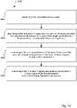
Figure 1c shows a schematic sequence diagram 1800 to operate the ODFM-modulator 1000 comprisingsteps -
Figure 1d shows a schematic sequence diagram 2800 to operate an OFDM-demodulator 2000 comprisingsteps -
Figure 2 shows a schematic cellular radio communications network RCN. The cellular radio communications network RCN is a cellular network, wherein the first radio device BS establishes a radio cell C. The first radio device BS is a base station, a LTE eNodeB, a 5G transmission point, a WiFi access point, a remote radio head, RRH, or else. The first radio device BS is in particular suitable to serve the radio cell C and to connect user equipment in the sense of radio devices UE, UE_leg inside the radio cell C to the cellular radio communications network RCN. The first radio device BS is e.g. implemented as a stand-alone equipment. - The second and third radio devices UE, UE_leg reside in the radio cell C and may be referred to as user equipment or machine equipment.
- The third radio device UE_leg is a LTE legacy device and fulfils 3GPP TS36.211 V14.00 Sep. 2016 The first and second radio devices BS and UE comprise an OFDM-
modulator 1000 and/or an OFDM-demodulator 2000, respectively. Many of the embodiments of this description allow operating the third radio device UE_leg in the cell C together with the first and second radio devices BS and UE. - The first radio device BS comprises a memory M1, a processor P1, a radio module R1, and an antenna A1. The second radio device UE comprises a memory M2, the processor P2, a radio module R2, and an antenna A2. The third radio device UE_leg comprises a memory and 3, processor P3, a radio module are 3 and an antenna A1. The processors P1, P2, P3 are implemented using e.g. a DSP, FPGA, or the like or a combination thereof. The memory M1, M2, M3 is implemented using e.g. a RAM, ROM, DDR, Flash memory, or the like, or a combination thereof. The memory M1, M2, M3 stores e.g. computer readable instructions, thus instructions executable by the processor P1, P2, P3. The processor P1 processes data to be transmitted to the first and second radio device UE, UE_leg. The processing includes the steps necessary to fulfil the requirements set by the radio communications network RCN.
- At least parts of the above described cellular radio communications network RCN including sender and/or receiver of the first radio device BS could be implemented using network functions virtualization (NFV). NFV is a network architecture that makes use of technologies of computer virtualization. Entire network equipment like sender or receiver or parts thereof or part of their functions can be virtualized using software building blocks that may connect, or interact, to create communication services. A virtualized network function of e.g. a sender or receiver may include at least one virtual machine running different software and processes, on top of standard high-volume servers, switches and storage, or a cloud computing infrastructure, instead of having customized hardware appliances for each network function. As such a sender or receiver function may be implemented in a computer program using a computer program product embodied on a non-transitory computer readable medium for performing operations, wherein the computer program product comprises instructions, that when executed by a processor, perform the operations of the specific base station, eNodeB, network node, MME (Mobility Management Entity) and/or UE function.
- The methods described herein relate to digital signal processing and could thus be implemented using a processor like a digital signal processor, or the like. At least some of the functions relate to baseband processing and could thus be implemented using a transceiver, e.g. a baseband transceiver. The radio module is e.g. a radio module, or a remotely located so called RRH (Remote Radio Head). The constellation with a RRH is often used in connection with a so called NFV (Network Functions Virtualization) implementation, where a substantial part of processing is centralized in a server farm with a plurality of processors and a plurality of memory, and the radio specific up-conversion, the antenna and the digital-to-analog converter for data transmission in downlink to the user equipment and the analog-to-digital converter for receiving data from the user equipment in uplink is remotely located. The radio module is also called radio frontend and includes e.g. a digital-to-analog converter, a low-pass filter, a mixer, a local oscillator, a power amplifier and an antenna. The local oscillator generates the radio frequency which is mixed on the processed data. The aforementioned modules/functions could be placed in serial order. Some modules might be not be used or replaced by others dependent on the technology used. For MIMO or massive MIMO some modules need to be duplicated, e.g. a plurality of antennas is used instead of one and corresponding amplifiers, etc. Additional modules might be added for performing und/or supporting specific functions as e.g. beamforming, CoMP (coordinated multipoint), eICIC (enhanced inter-cell interference control), or the like. User equipment (UE) could be implemented as a device with a radio module, e.g. smartphone, tablet, smartwatch, sensor, actuator, equipment inside a vehicle, machine-to-machine equipment, or else. The radio communications network RCN is an OFDM (Orthogonal Frequency Division Multiplex) type network, e.g. UF-OFDM, F-OFDM, ZT-s-OFDM, P-OFDM, FC-OFDM, or another multi-carrier network, e.g. FS-FBMC, QAM-FBMC, etc. E.g. QAM - Quadrature Amplitude Modulation and/or QPSK - Quadrature Phase Shift Keying are used as modulation technique. The radio network RCN allocates resources using a scheduler and a time-frequency-resource grid, a t-f-resource. The t-f-resource includes time slots and associated subcarriers. The subcarriers are e.g. grouped in frequency subbands. A subband is assigned at least one subband parameter. A subband parameter is e.g. subcarrier spacing, other parameters are e.g. symbol duration, time overhead, time overhead type like zero postfix or cyclic prefix, windowing or filtering parameters. Dependent on the assigned or selected parameters the subband is characterized for a specific transmission type and is in particular suitable for the transmission of specific services. A service is e.g. eMBB (enhanced mobile broadband), mMTC (massive machine-type-communication), URLLC (ultra reliable low latency communication), vehicle-to-vehicle communication, voice, video, etc. An allocated physical resource block thus assigns a dedicated time slot associated with one or more subcarriers or a subband to a data packet. A physical resource block assigns one time slot to a subcarrier. A time slot is e.g. called a TTI (transmission time interval). The period of time could e.g. be one or more time slots. Data and control signals are transmitted using physical channels, e.g. physical downlink shared channel, physical downlink control channel, common control physical channel. Further data and control signals could be transmitted using broadcast channel, paging channel, multicast channel.
-
Figure 3 shows a schematic block diagram of the ODFM-modulator 1000 with a plurality ofprocessing chains third processing chain 1100 is described in detail in the following, wherein the further processing chains are similar to theprocessing chain 1100 but may differ at least in the used respective block lengths and frequency offsets. Ablock 1106 determines a third ingress modulation-symbol stream a0,...,aN-1 in dependence on a thirdingress data stream 1108. Theblock 1106 may comprise an QAM-modulator (Quadrature Amplitude Modulation) and/or an QPSK-modulator (Quadrature Phase Shift Keying), a channel pre-coder, and/or for further processing entities. A serial-to-parallel converter 1110 converts the third ingress modulation-symbol stream a0,...aN-1 from a parallel to a serial symbol stream. The parallelized third ingress modulation-symbol stream a0,...aN-1 is applied to asubcarrier mapper 1112. Amapper 1114 maps reference symbols and/or synchronisation symbols to the modulation-symbol stream. The modulation-symbol stream determined by themapper 1114 is applied to an inverse FastFourier Transform block 1118 to determine the third inverse Fast Fourier Transform IFFTA. Afrequency shifter 1116 shifts the applied third inverse Fast Fourier Transform IFFTA by the applied third frequency offset Δf1 to determine third frequency-shifted samples Sa. The third frequence-shifted samples Sa are serialized by means of a parallel-to-serial converter 1120 and applied to a cyclic prefix (CP)inserter 1122 to determine the third egress sample stream d0,...,dA-1. Thecyclic prefix inserter 1122 also can be omitted. - The
processing chains processing chain 1100 as described above in the following: Theingress data streams parallel converters Fourier Transform block - Given the largest block length of the fourier transform in the sense of the main block length A, each processing chain has to fulfil the following equation (1) with a block length bl and the corresponding K-factor K.

- For cellular radio communications network RCN with the main block length A of 2048 also legacy LTE devices can be attended. In this case the subcarrier spacing f0 providing a fixed subcarrier spacing grid for all of the other processing chains is 15 kHz. Of course, the main block length A can be chosen differently, however loosing compatibility with legacy LTE devices. The sample time Ts for each K-Factor system can be determined according to equation (2).

- For applications with a demand for low energy consumption and short symbol rates, the second radio device UE may only comprise processing chains with a high K-Factor, particularly a K-factor K greater than 1.
- The following equations (3) to (6) show that the modulation and demodulation scheme proposed in this description still provides that the subcarriers are orthogonal. Equation (3) provides the forward Fast Fourier Transform FFT_R of block length R with the parameter k. In equation (4) the right hand term is separated into two components X_I and X_II each representing Fast Fourier Transforms. Equation (5) comprises a parameter transform from parameter k of equation (4) to the parameter 2*u. Equation (6) represents equation (5) in a rewritten form. Equations (5) and (6) provide two fourier transforms XI(u) and XII(u) with a block length of R/2 in comparison with the Fast Fourier Transform of block length R in equations (3) and (4). Consequently, subcarrier orthogonality is maintained while FFT block lengths are used that comply with the K-factor scheme described in equation (1).


- The following table 1 shows possible configurations for processing chains of the OFDM-
modulator 1000 and the OFDM-demodulator 2000.Table 1 FFT Lengt h Num N of PRBs K-Factor N * K Symbol Length in µs Bandwidth Integrat ion in LTE 20MHz 16 1 128 128 0,5 23,04MHz No 32 1 64 64 1,0 11,52MHz Yes 64 1 32 32 2,1 5,76MHz Yes 2 64 11,52MHz 3 96 17,28MHz 128 1 16 16 4,2 2,88MHz Yes 2 32 5,76MHz 3 48 8,64MHz 4 64 11,52MHz 5 80 14,40MHz 6 96 17,28MHz 256 1 8 8 8,33 1,44MHz Yes 2 16 2,88MHz 3 24 4,32MHz 4 32 5,76MHz 5 40 7,20MHz 6 48 8,64MHz 7 56 10,08MHz 8 64 11,52MHz 9 72 12,96MHz 10 80 14,40MHz 11 88 15,84MHz 12 96 17,28MHz 512 1 4 4 16,65 0,72MHz Yes 2 8 1,44MHz 3 12 2,16MHz 4 16 2,88MHz 5 20 3,60MHz 6 24 4,32MHz 7 28 5,04MHz 8 32 5,76MHz 9 36 6,48MHz 10 40 7,20MHz 11 44 7,92MHz 12 48 8,64MHz 13 52 9,36MHz 14 56 10,08MHz 15 60 10,80MHz 16 64 11,52MHz 17 68 12,24MHz 18 72 12,96MHz 19 76 13,68MHz 20 80 14,40MHz 21 84 15,12MHz 22 88 15,84MHz 23 92 16,56MHz 24 96 17,28MHz 25 100 18,00MHz 1024 1 2 2 33,3 0,36MHz Yes 2 4 0,72MHz 3 6 1,08MHz 4 8 1,44MHz 5 10 1,80MHz 6 12 2,16MHz 7 14 2,52MHz 8 16 2,88MHz 9 18 3,24MHz 10 20 3,60MHz 11 22 3,96MHz 12 24 4,32MHz 13 26 4,68MHz 14 28 5,04MHz 15 30 5,40MHz 16 32 5,76MHz 17 34 6,12MHz 18 36 6,48MHz 19 38 6,84MHz 20 40 7,20MHz 21 42 7,56MHz 22 44 7,92MHz 23 46 8,28MHz 24 48 8,64MHz 25 50 9,00MHz LTE: 2048 1 ... 100 1 1 ... 100 66, 6 0, 18...18MH z Yes - In table 2 the surviving subcarrier distance in kHz depending on the K factor is shown. The subcarrier distance means that for a system with the corresponding K factor a multiple of the subcarrier distance survive in the frequency range. Consequently, with a rising K factor also the subcarrier distance rises and the corresponding frequency space can be used according to the methods described herein. Therefore, shorter symbol times result in an increase of capacity, if all subcarriers are used.
Table 2 K-factor Subcarrier distance in kHz for surviving subcarriers 1 15 2 30 4 40 8 120 16 240 - The absolute value of the difference between first and second frequency offset Δf2, Δf3 is in a range between and including one subcarrier and K-1 subcarriers.
- An
adder 1902 adds the first, second and third egress sample streams e0,...,eB-1, f0,...,fB-1, d0,...,dA-1, to a sum, namely the joined sample stream g0,...gA-1. The joined sample stream g0,..,gA-1 is applied to a digital-to-analog converter of the respective radio module R1, R2 and subsequently up-converted to a carrier frequency higher than respective subcarrier frequencies. - The wording ingress and egress has the meaning that a respective ingress stream is located toward an input side of the processing chain and that an egress stream is located toward an output side of the processing chain. Therefore, the ingress stream may differ from an actual input stream at the beginning of the processing chain. The same applies to the egress stream.
- The serial-to-parallel converters and the parallel-to-serial converters in
figures 3 and4 are arranged at an exemplary position. Of course these converters can be arranged at other positions to optimize the respective processing chain. -
Figure 4 shows schematic block diagram of an OFDM-demodulator 2000 with a plurality ofprocessing chains processing chain 2100 is described in detail in the following, wherein the further processing chains are similar to theprocessing chain 2100. Acyclic prefix remover 2108 removes a cyclic prefix CP. The cyclic prefix remover 2108 can also be omitted. Thefrequency shifter 2110 back-shifts the down-converted sample stream h0,...,hA-1,... not comprising the cyclic prefix in dependence on the supplied third frequency offset Δf1. Thefrequency shifter 2110 determines the third ingress sample stream i0,...,iA-1, which is parallelized by a serial-to-parallel converter 2112. A forward FastFourier Transform block 2114 determines the third forward Fast Fourier Transform FFTA of the further block size A in dependence on the parallelised ingress sample stream i0,...,iA-1. Ademapper 2116 demaps the subcarriers. A parallel-to-serial converter 2118 of block length N determines the third egress demodulation-symbol stream m0,...,mN-1 in dependence on the third forward Fast Fourier Transform FFTA. Achannel estimator 2120 determines achannel estimate 2122 in dependence on reference symbols contained in the third egress demodulation-symbol stream m0,...,mV-1. Anequalizer 2124 determines an equalized egress modulation-symbol stream 2126 in dependence on the third egress demodulation-symbol stream m0,...,mN-1 and in dependence on thechannel estimate 2122. As indicated with arrows the channel estimates 2122 and 2222 can be exchanged, wherein for example theestimator 2120 receives thechannel estimate 2222. Ablock 2128 determines anegress data stream 2130 in dependence on the equalized egress demodulation-symbol stream 2126. Thechannel estimator 2120 and theequalizer 2124 are only exemplary and may comprise other taps regarding the respective input and output symbol streams. Theblock 2128 comprises a QAM-demodulator (Quadrature Amplitude Modulation) and/or a QPSK-demodulator (Quadrature Phase Shift Keying), a channel de-coder, and/or further processing entities. Theegress data stream 2130 equals theingress data stream 1108 infigure 3 . Acorrelator 2132 detects a synchronization symbol in the third egress demodulation-symbol stream m0,...,mN-1 and determines asynchronisation state 2134. - The
processing chains processing chain 2100 as described above in the following: Theegress data streams -
Figure 5 shows a schematic block diagram of the ODFM-demodulator 2000. According to theblock 2110 no frequency back-shift is applied to the down-converted sample stream h0,...,hA-1,... and the third forward Fast Fourier transform FFTA is determined inblock 2114.Further processing chains - A
processing chain group 2600 comprises theprocessing chains group 2600 are characterized by using the same block length B, in this example with a value of 128, and a frequency offset scheme. According to the frequency offset scheme the frequency offsets for the processing chains of theprocessing chain group 2600 are determined on a subcarrier basis in order to use unused subcarrier subspaces of a single one of the processing chains. -
Figure 6 illustrates schematically a frequency offset scheme on subcarrier basis for the block length 128. As the block length 128 corresponds to a K-factor of 16, operating a single processing chain with a K-factor of 16 in the OFDM-modulator 1000 will result in used subcarriers mod(j, 16) = 0 in a frequency range FR, wherein j is the subcarrier index. In the same frequency range FR the remaining subcarriers are used by means of at least one further processing chain in the OFDM-modulator 1000 and the ODFM-demodulator 2000. - The OFDM-
modulator 1000 determines the first frequency offset Δf2 for the first inverse Fast Fourier Transform IFFTB1, wherein the first inverse Fast Fourier Transform IFFTB1 occupies a first subcarrier subset sc0A, sc0B, sc0C in the subcarrier range SR. The second frequency offset Δf3 for the second inverse Fast Fourier Transform IFFTB2 is determined, so that the second inverse Fast Fourier Transform IFFTB2 occupies a second subcarrier subset sc3A, sc3B, sc3C in the subcarrier range SR. The first and second frequency offsets Δf2, Δf3 in the shown example offigure 6 differ by three subcarriers. Further subcarrier subsets are shown in the frequency range and exemplify a comb-like inverleaving of the subsets. Moreover, all the subsets of the frequency offset scheme use mutually different subcarriers in the frequency range FR. In an embodiment guard bands in the sense of one or more unused subcarriers are arranged between subcarriers in the frequency range FR. - The functions of the various elements shown in the FIGs., including any functional blocks labelled as "processors", may be provided through the use of dedicated hardware as well as hardware capable of executing software in association with appropriate software. When provided by a processor, the functions may be provided by a single dedicated processor, by a single shared processor, or by a plurality of individual processors, some of which may be shared. Moreover, explicit use of the term "processor" or "controller" should not be construed to refer exclusively to hardware capable of executing software, and may implicitly include, without limitation, digital signal processor (DSP) hardware, network processor, application specific integrated circuit (ASIC), field programmable gate array (FPGA), read only memory (ROM) for storing software, random access memory (RAM), and non volatile storage. Other hardware, conventional and/or custom, may also be included. Similarly, any switches shown in the FIGS. are conceptual only. Their function may be carried out through the operation of program logic, through dedicated logic, through the interaction of program control and dedicated logic, or even manually, the particular technique being selectable by the implementer as more specifically understood from the context.
- It should be appreciated by those skilled in the art that any block diagrams herein represent conceptual views of illustrative circuitry embodying the principles of the invention. Similarly, it will be appreciated that any flow charts, flow diagrams, state transition diagrams, pseudo code, and the like represent various processes which may be substantially represented in computer readable medium and so executed by a computer or processor, whether or not such computer or processor is explicitly shown.
Claims (9)
- An OFDM-modulator (1000) for operating in a radio device (BS; UE) of a cellular radio communications network (RCN), wherein the OFDM-modulator (1000) comprises a processor (P1; P2) and a memory (M1; M2) being configured to:- receive a first and second ingress modulation-symbol stream (b0,...,bM-1, c0,...,cP-1);- receive a third ingress modulation-symbol stream (a0,...,aN-1);- determine a first and second inverse Fast Fourier Transform (IFFTB1, IFFTB2) of the same first block length (B) in dependence on the first and second ingress modulation-symbol stream (b0,...,bM-1, c0,...,cP-1), respectively;- determine a third inverse Fast Fourier Transform (IFFTA) of a second block length (A) in dependence on the third ingress modulation-symbol stream (a0,...,aN-1), wherein the first block length (B) multiplied with an integer factor (K) is equal to the second block length (A) ;- determine first and second frequency-shifted samples (Sb2; Sb3) of different frequency offsets (Δf2, Δf3) to a subcarrier frequency (DC) in dependence on the first and second inverse Fast Fourier Transform (IFFTB1, IFFTB2), respectively, wherein the different frequency offsets (Δf2, Δf3) are determined on a subcarrier basis in order to use subcarrier subspaces;- determine third frequency-shifted samples (Sa) of a third frequency offset (Δf1) to the subcarrier frequency (DC) in dependence on the third inverse Fast Fourier Transform (IDFTA);- determine the first frequency offset (Δf2) for the first inverse Fast Fourier Transform (IFFTB1), wherein the first inverse Fast Fourier Transform (IFFTB1) occupies a first subcarrier subset in a subcarrier range (SR);- determine the second frequency offset (Δf3) for the second inverse Fast Fourier Transform (IFFTB2), wherein the second inverse Fast Fourier Transform (IFFTB2) occupies a second subcarrier subset in the subcarrier range (SR);- wherein the first and second subcarrier subsets are interleaved comb-like;- determine a first and second egress sample stream (e0,...,eB-1, f0,...,fB-1) in dependence on the first and second frequency-shifted samples (Sb2; Sb3), respectively;- determine a third egress sample stream (c0,...,cA-1) in dependence on the third frequency-shifted samples (Sa) ; and- determine a joined sample stream (g0,...gB-1) in dependence on the first, second and third egress sample stream (e0,...,eB-1, f0,...,fB-1, c0,...,cA-1) for up-converting the joined sample stream (g0,...,gB-1) to a carrier frequency higher than respective subcarrier frequencies.
- The OFDM-modulator (1000) according to claim 1,- wherein the same first block length (B) of the first and second inverse Fast Fourier Transform (IFFTB) multiplied with an integer factor (K) greater than one equals a main block length (A).
- The OFDM-modulator (1000) according to claim 2,- wherein the main block length (A) equals 2048.
- An OFDM-demodulator (2000) for operating in a device (BS; UE) of a cellular radio communications network (RCN), wherein the OFDM-demodulator (2000) comprises a processor (P1; P2) and a memory (M1; M2) being configured to:- receive a down-converted sample stream (h0,...,hB-1...);- determine a first and second ingress sample stream (k0,...kB-1, l0,...,lB-1) of the down-converted sample stream (h0,...,hB-1,...) of the same first block length (B) and of different frequency offsets (-Δf2, -Δf3) to a subcarrier frequency (DC), respectively;- wherein the first ingress sample stream (k0,...,kB-1) comprises a first inverse Fast Fourier Transform (IFFTB1) occupying a first subcarrier subset in a subcarrier range (SR);- wherein the second ingress sample stream (l0,...,lB-1) comprises a second inverse Fast Fourier Transform (IFFTB2) occupying a second subcarrier subset in the subcarrier range (SR);- wherein the first and second subcarrier subsets are interleaved comb-like;- determine a third ingress sample stream (i0,...,iA-1) of the down-converted sample stream (h0,...,hA-1) of a second block length (A) and of a third frequency offset (Δf1), wherein the first block length (B) multiplied with an integer factor (K) is equal to the second block length (A);- determine a first and second forward Fast Fourier Transform (FFTB1, FFTB2) of the same first block length (B) in dependence on the first and second ingress sample stream (k0,...,kB-1, l0,...,lB-1), respectively;- determine a third forward Fast Fourier Transform (DFTA) of the further block length (A) in dependence on the third ingress sample stream (i0,...,iA-1);- determine a first and second egress demodulation-symbol stream (n0,...,nM-1, o0,...oP-1) in dependence on the first and second forward Fast Fourier Transform (FFTB1, FFTB2), respectively; and- determine a third egress demodulation-symbol stream (m0,...nM-1) in dependence on the third forward Fast Fourier Transform (DFTA).
- The OFDM-demodulator (2000) according to claim 4,- wherein the same first block length (B) of the first and second forward Fast Fourier Transform (DFTB) multiplied with an integer factor (K) greater than one equals a main block length (A).
- The OFDM-demodulator (2000) according to claim 5,- wherein the main block length (A) equals 2048.
- A radio device (BS; UE) for operating in a cellular radio communications network (RCN), wherein the radio device (BS; UE) comprises:- the OFDM-modulator (1000) according to one of the claims 1 to 3, wherein the radio device (BS; UE) comprises a radio module (R1; R2) and an antenna (A1; A2) being configured to:- up-convert the joined sample stream (g0,...,gA-1) to the carrier frequency higher than respective subcarrier frequencies;- transmit the joined sample stream (g0,...,gA-1) on a first radio channel (ch1; ch2); and/or wherein the radio device (BS; UE) comprises the OFDM-demodulator (2000) according to one of the claims 4 to 6, wherein the radio device (BS; UE) comprises the radio module (R1; R2) and the antenna (A1;A2) being configured to:- receive a radio signal from a second channel (ch2; ch1) ;- down-convert the radio signal to the ingress sample stream (h0,...,hA-1,...).
- A method to operate an OFDM-modulator (1000) for operating in a radio device (BS; UE) of a cellular radio communications network (RCN), wherein the method comprises:- receiving a first and second ingress modulation-symbol stream (b0,bM-1, c0,...,cP-1);- receive a third ingress modulation-symbol stream (a0,...,aN-1);- determining a first and second inverse Fast Fourier Transform (IFFTB1, IFFTB2) of the same first block length (B) in dependence on the first and second ingress modulation-symbol stream (b0,...,bM-1, c0,...,cP-1), respectively;- determining a third inverse Fast Fourier Transform (IFFTA) of a second block length (A) in dependence on the third ingress modulation-symbol stream (a0, aN-1), wherein the first block length (B) multiplied with an integer factor (K) is equal to the second block length (A) ;- determining first and second frequency-shifted samples (Sb2; Sb3) of different frequency offsets to a subcarrier frequency (DC) in dependence on the first and second inverse Fast Fourier Transform (IFFTB1, IFFTB2), respectively;- determining the first frequency offset (Δf2) for the first inverse Fast Fourier Transform (IFFTB1), wherein the first inverse Fast Fourier Transform (IFFTB1) occupies a first subcarrier subset in a subcarrier range (SR);- determining the second frequency offset (Δf3) for the second inverse Fast Fourier Transform (IFFTB2), wherein the second inverse Fast Fourier Transform (IFFTB2) occupies a second subcarrier subset in the subcarrier range (SR);- wherein the first and second subcarrier subsets are interleaved comb-like;- determining third frequency-shifted samples (Sa) of a third frequency offset (Δf1) to the subcarrier frequency (DC) in dependence on the third inverse Fast Fourier Transform (IDFTA);- determining a first and second egress sample stream (e0,...,eB-1, f0,...,fB-1) in dependence on the first and second frequency-shifted samples (Sb2; Sb3), respectively;- determining a third egress sample stream (c0,...,cA-1) in dependence on the third frequency-shifted samples (Sa) ; and- determing a joined sample stream (g0,...gB-1) in dependence on the first, second and third egress sample stream (e0,...,eB-1, f0,...,fB-1, c0,...,cA-1) for up-converting the joined sample stream (g0,...gB-1) to a carrier frequency higher than respective subcarrier frequencies.
- A method to operate an OFDM-demodulator (2000) for operating in a device (BS; UE) of a cellular radio communications network (RCN), wherein the method comprises:- receiving a down-converted sample stream (h0,...,hB-1,...);- determining a first and second ingress sample stream (k0,...,kB-1, l0,...,lB-1) of the down-converted demodulation-symbol stream (h0,...,hB-1,...) of the same first block length (B) and of different frequency offset (-Δf2, -Δf3) to a subcarrier frequency (DC), respectively;- wherein the first ingress sample stream (k0,...,kB-1) comprises a first inverse Fast Fourier Transform (IFFTB1) occupying a first subcarrier subset in a subcarrier range (SR);- wherein the second ingress sample stream (l0,...,lB-1) comprises a second inverse Fast Fourier Transform (IFFTB2) occupying a second subcarrier subset in the subcarrier range (SR);- wherein the first and second subcarrier subsets are interleaved comb-like;- determining a third ingress sample stream (i0,...,iA-1) of the down-converted sample stream (h0,...,hA-1) of a second block length (A) and of a third frequency offset (Δf1), wherein the first block length (B) multiplied with an integer factor (K) is equal to the second block length (A);- determining a first and second forward Fast Fourier Transform (FFTB1, FFTB2) of the same block length (B) in dependence on the first and second ingress sample stream (k0,...,kB-1, l0,...,lB-1), respectively;- determine a third forward Fast Fourier Transform (DFTA) of the further block length (A) in dependence on the third ingress sample stream (i0,...,iA-1);- determining a first and second egress demodulation-symbol stream (n0,...,nM-1, o0,...oP-1) in dependence on the first and second forward Fast Fourier Transform (FFTB1, FFTB2), respectively; and- determine a third egress demodulation-symbol stream (m0,...,nM-1) in dependence on the third forward Fast Fourier Transform (DFTA).
Priority Applications (4)
| Application Number | Priority Date | Filing Date | Title |
|---|---|---|---|
| EP16306692.1A EP3337115B1 (en) | 2016-12-15 | 2016-12-15 | Combining different ofdm numerologies in one band |
| PCT/EP2017/081738 WO2018108677A1 (en) | 2016-12-15 | 2017-12-06 | Ofdm-modulator, ofdm-demodulator, method to operate an ofdm-modulator, and method to operate an ofdm-demodulator |
| JP2019531894A JP2020502921A (en) | 2016-12-15 | 2017-12-06 | OFDM modulator, OFDM demodulator, method of operating OFDM modulator, and method of operating OFDM demodulator |
| JP2022129904A JP2022166204A (en) | 2016-12-15 | 2022-08-17 | Ofdm modulator, ofdm demodulator, method of operating ofdm modulator, and methods of operating ofdm demodulator |
Applications Claiming Priority (1)
| Application Number | Priority Date | Filing Date | Title |
|---|---|---|---|
| EP16306692.1A EP3337115B1 (en) | 2016-12-15 | 2016-12-15 | Combining different ofdm numerologies in one band |
Publications (2)
| Publication Number | Publication Date |
|---|---|
| EP3337115A1 EP3337115A1 (en) | 2018-06-20 |
| EP3337115B1 true EP3337115B1 (en) | 2022-03-30 |
Family
ID=57590447
Family Applications (1)
| Application Number | Title | Priority Date | Filing Date |
|---|---|---|---|
| EP16306692.1A Active EP3337115B1 (en) | 2016-12-15 | 2016-12-15 | Combining different ofdm numerologies in one band |
Country Status (3)
| Country | Link |
|---|---|
| EP (1) | EP3337115B1 (en) |
| JP (2) | JP2020502921A (en) |
| WO (1) | WO2018108677A1 (en) |
Family Cites Families (2)
| Publication number | Priority date | Publication date | Assignee | Title |
|---|---|---|---|---|
| JP3515690B2 (en) * | 1998-06-02 | 2004-04-05 | 松下電器産業株式会社 | OFDMA signal transmission apparatus and method |
| US10038581B2 (en) * | 2015-06-01 | 2018-07-31 | Huawei Technologies Co., Ltd. | System and scheme of scalable OFDM numerology |
-
2016
- 2016-12-15 EP EP16306692.1A patent/EP3337115B1/en active Active
-
2017
- 2017-12-06 JP JP2019531894A patent/JP2020502921A/en active Pending
- 2017-12-06 WO PCT/EP2017/081738 patent/WO2018108677A1/en active Application Filing
-
2022
- 2022-08-17 JP JP2022129904A patent/JP2022166204A/en active Pending
Non-Patent Citations (2)
| Title |
|---|
| INTEL CORPORATION: "Multiplexing of different numerologies for forward compatibility", vol. RAN WG1, no. Gothenburg, Sweden; 20160822 - 20160826, 13 August 2016 (2016-08-13), XP051133001, Retrieved from the Internet <URL:http://www.3gpp.org/ftp/tsg_ran/WG1_RL1/TSGR1_86/Docs/> [retrieved on 20160813] * |
| NOKIA ET AL: "On the URLLC transmission formats for NR TDD", vol. RAN WG1, no. Gothenburg, Sweden; 20160822 - 20160826, 12 August 2016 (2016-08-12), XP051142024, Retrieved from the Internet <URL:http://www.3gpp.org/ftp/tsg_ran/WG1_RL1/TSGR1_86/Docs/> [retrieved on 20160812] * |
Also Published As
| Publication number | Publication date |
|---|---|
| WO2018108677A1 (en) | 2018-06-21 |
| JP2020502921A (en) | 2020-01-23 |
| JP2022166204A (en) | 2022-11-01 |
| EP3337115A1 (en) | 2018-06-20 |
Similar Documents
| Publication | Publication Date | Title |
|---|---|---|
| EP3429153B1 (en) | Ofdm based wireless communication with flexible sub-carrier spacing and symbol duration | |
| CN108781446B (en) | Single carrier uplink control and multi-carrier uplink data | |
| EP2277295B1 (en) | Radio access method for reduced papr | |
| EP3985909B1 (en) | Method and apparatus for transmitting dmrs | |
| CN110506442B (en) | Group common control channel | |
| CN110620644B (en) | OFDM communication system having a method for determining subcarrier offset generated by OFDM symbols | |
| CN109644063B (en) | Method for transmitting and receiving synchronization signal in wireless communication system and apparatus therefor | |
| CN109565414B (en) | Apparatus and user equipment for processing channel state information reference signal | |
| JP7145273B2 (en) | Wireless transmission device and transmission method | |
| EP3487106A1 (en) | Communication method and apparatus | |
| EP3687104B1 (en) | Method and apparatus for generating nb-iot ofdm signals with a lower sampling rate | |
| US9871607B1 (en) | Phase continuity in narrow-band transmission within a frequency-domain multiple-access communication system | |
| EP3595223B1 (en) | Method and device for sending demodulation reference signal, demodulation method and device | |
| JP6882479B2 (en) | A method for transmitting and receiving signals between a terminal and a base station in a wireless communication system and a device for supporting the signal. | |
| WO2016184503A1 (en) | Enhancing data transfer | |
| GB2565342A (en) | Pilot signals | |
| EP2903198A1 (en) | Method and apparatus for exchanging information | |
| EP3337114B1 (en) | Combining different ofdm numerologies in one band | |
| EP3337115B1 (en) | Combining different ofdm numerologies in one band | |
| US8379565B2 (en) | Method for mapping subband/miniband in wireless communication system and an apparatus therefor | |
| EP3337116B1 (en) | Combining smaller ffts to receive signal modulated by larger ifft | |
| EP3337283B1 (en) | A method for managing a cellular radio communications network, a management device, a method to operate a first radio device, a first radio device, a method to operate a second radio device, and a second radio device | |
| KR101365616B1 (en) | Method for configuring subchannels in wireless communication system and apparatus therefor |
Legal Events
| Date | Code | Title | Description |
|---|---|---|---|
| PUAI | Public reference made under article 153(3) epc to a published international application that has entered the european phase |
Free format text: ORIGINAL CODE: 0009012 |
|
| STAA | Information on the status of an ep patent application or granted ep patent |
Free format text: STATUS: THE APPLICATION HAS BEEN PUBLISHED |
|
| AK | Designated contracting states |
Kind code of ref document: A1 Designated state(s): AL AT BE BG CH CY CZ DE DK EE ES FI FR GB GR HR HU IE IS IT LI LT LU LV MC MK MT NL NO PL PT RO RS SE SI SK SM TR |
|
| AX | Request for extension of the european patent |
Extension state: BA ME |
|
| STAA | Information on the status of an ep patent application or granted ep patent |
Free format text: STATUS: REQUEST FOR EXAMINATION WAS MADE |
|
| 17P | Request for examination filed |
Effective date: 20181220 |
|
| RBV | Designated contracting states (corrected) |
Designated state(s): AL AT BE BG CH CY CZ DE DK EE ES FI FR GB GR HR HU IE IS IT LI LT LU LV MC MK MT NL NO PL PT RO RS SE SI SK SM TR |
|
| STAA | Information on the status of an ep patent application or granted ep patent |
Free format text: STATUS: EXAMINATION IS IN PROGRESS |
|
| 17Q | First examination report despatched |
Effective date: 20191008 |
|
| STAA | Information on the status of an ep patent application or granted ep patent |
Free format text: STATUS: EXAMINATION IS IN PROGRESS |
|
| GRAP | Despatch of communication of intention to grant a patent |
Free format text: ORIGINAL CODE: EPIDOSNIGR1 |
|
| STAA | Information on the status of an ep patent application or granted ep patent |
Free format text: STATUS: GRANT OF PATENT IS INTENDED |
|
| GRAJ | Information related to disapproval of communication of intention to grant by the applicant or resumption of examination proceedings by the epo deleted |
Free format text: ORIGINAL CODE: EPIDOSDIGR1 |
|
| GRAP | Despatch of communication of intention to grant a patent |
Free format text: ORIGINAL CODE: EPIDOSNIGR1 |
|
| STAA | Information on the status of an ep patent application or granted ep patent |
Free format text: STATUS: GRANT OF PATENT IS INTENDED |
|
| INTG | Intention to grant announced |
Effective date: 20211011 |
|
| RIN1 | Information on inventor provided before grant (corrected) |
Inventor name: FUCHS, ROLF Inventor name: RHEINSCHMITT, RUPERT |
|
| INTG | Intention to grant announced |
Effective date: 20211027 |
|
| GRAS | Grant fee paid |
Free format text: ORIGINAL CODE: EPIDOSNIGR3 |
|
| GRAA | (expected) grant |
Free format text: ORIGINAL CODE: 0009210 |
|
| STAA | Information on the status of an ep patent application or granted ep patent |
Free format text: STATUS: THE PATENT HAS BEEN GRANTED |
|
| AK | Designated contracting states |
Kind code of ref document: B1 Designated state(s): AL AT BE BG CH CY CZ DE DK EE ES FI FR GB GR HR HU IE IS IT LI LT LU LV MC MK MT NL NO PL PT RO RS SE SI SK SM TR |
|
| REG | Reference to a national code |
Ref country code: GB Ref legal event code: FG4D |
|
| REG | Reference to a national code |
Ref country code: CH Ref legal event code: EP |
|
| REG | Reference to a national code |
Ref country code: AT Ref legal event code: REF Ref document number: 1480210 Country of ref document: AT Kind code of ref document: T Effective date: 20220415 |
|
| REG | Reference to a national code |
Ref country code: DE Ref legal event code: R096 Ref document number: 602016070455 Country of ref document: DE |
|
| REG | Reference to a national code |
Ref country code: IE Ref legal event code: FG4D |
|
| REG | Reference to a national code |
Ref country code: LT Ref legal event code: MG9D |
|
| PG25 | Lapsed in a contracting state [announced via postgrant information from national office to epo] |
Ref country code: SE Free format text: LAPSE BECAUSE OF FAILURE TO SUBMIT A TRANSLATION OF THE DESCRIPTION OR TO PAY THE FEE WITHIN THE PRESCRIBED TIME-LIMIT Effective date: 20220330 Ref country code: RS Free format text: LAPSE BECAUSE OF FAILURE TO SUBMIT A TRANSLATION OF THE DESCRIPTION OR TO PAY THE FEE WITHIN THE PRESCRIBED TIME-LIMIT Effective date: 20220330 Ref country code: NO Free format text: LAPSE BECAUSE OF FAILURE TO SUBMIT A TRANSLATION OF THE DESCRIPTION OR TO PAY THE FEE WITHIN THE PRESCRIBED TIME-LIMIT Effective date: 20220630 Ref country code: LT Free format text: LAPSE BECAUSE OF FAILURE TO SUBMIT A TRANSLATION OF THE DESCRIPTION OR TO PAY THE FEE WITHIN THE PRESCRIBED TIME-LIMIT Effective date: 20220330 Ref country code: HR Free format text: LAPSE BECAUSE OF FAILURE TO SUBMIT A TRANSLATION OF THE DESCRIPTION OR TO PAY THE FEE WITHIN THE PRESCRIBED TIME-LIMIT Effective date: 20220330 Ref country code: BG Free format text: LAPSE BECAUSE OF FAILURE TO SUBMIT A TRANSLATION OF THE DESCRIPTION OR TO PAY THE FEE WITHIN THE PRESCRIBED TIME-LIMIT Effective date: 20220630 |
|
| REG | Reference to a national code |
Ref country code: NL Ref legal event code: MP Effective date: 20220330 |
|
| REG | Reference to a national code |
Ref country code: AT Ref legal event code: MK05 Ref document number: 1480210 Country of ref document: AT Kind code of ref document: T Effective date: 20220330 |
|
| PG25 | Lapsed in a contracting state [announced via postgrant information from national office to epo] |
Ref country code: LV Free format text: LAPSE BECAUSE OF FAILURE TO SUBMIT A TRANSLATION OF THE DESCRIPTION OR TO PAY THE FEE WITHIN THE PRESCRIBED TIME-LIMIT Effective date: 20220330 Ref country code: GR Free format text: LAPSE BECAUSE OF FAILURE TO SUBMIT A TRANSLATION OF THE DESCRIPTION OR TO PAY THE FEE WITHIN THE PRESCRIBED TIME-LIMIT Effective date: 20220701 Ref country code: FI Free format text: LAPSE BECAUSE OF FAILURE TO SUBMIT A TRANSLATION OF THE DESCRIPTION OR TO PAY THE FEE WITHIN THE PRESCRIBED TIME-LIMIT Effective date: 20220330 |
|
| PG25 | Lapsed in a contracting state [announced via postgrant information from national office to epo] |
Ref country code: NL Free format text: LAPSE BECAUSE OF FAILURE TO SUBMIT A TRANSLATION OF THE DESCRIPTION OR TO PAY THE FEE WITHIN THE PRESCRIBED TIME-LIMIT Effective date: 20220330 |
|
| PG25 | Lapsed in a contracting state [announced via postgrant information from national office to epo] |
Ref country code: SM Free format text: LAPSE BECAUSE OF FAILURE TO SUBMIT A TRANSLATION OF THE DESCRIPTION OR TO PAY THE FEE WITHIN THE PRESCRIBED TIME-LIMIT Effective date: 20220330 Ref country code: SK Free format text: LAPSE BECAUSE OF FAILURE TO SUBMIT A TRANSLATION OF THE DESCRIPTION OR TO PAY THE FEE WITHIN THE PRESCRIBED TIME-LIMIT Effective date: 20220330 Ref country code: RO Free format text: LAPSE BECAUSE OF FAILURE TO SUBMIT A TRANSLATION OF THE DESCRIPTION OR TO PAY THE FEE WITHIN THE PRESCRIBED TIME-LIMIT Effective date: 20220330 Ref country code: PT Free format text: LAPSE BECAUSE OF FAILURE TO SUBMIT A TRANSLATION OF THE DESCRIPTION OR TO PAY THE FEE WITHIN THE PRESCRIBED TIME-LIMIT Effective date: 20220801 Ref country code: ES Free format text: LAPSE BECAUSE OF FAILURE TO SUBMIT A TRANSLATION OF THE DESCRIPTION OR TO PAY THE FEE WITHIN THE PRESCRIBED TIME-LIMIT Effective date: 20220330 Ref country code: EE Free format text: LAPSE BECAUSE OF FAILURE TO SUBMIT A TRANSLATION OF THE DESCRIPTION OR TO PAY THE FEE WITHIN THE PRESCRIBED TIME-LIMIT Effective date: 20220330 Ref country code: CZ Free format text: LAPSE BECAUSE OF FAILURE TO SUBMIT A TRANSLATION OF THE DESCRIPTION OR TO PAY THE FEE WITHIN THE PRESCRIBED TIME-LIMIT Effective date: 20220330 Ref country code: AT Free format text: LAPSE BECAUSE OF FAILURE TO SUBMIT A TRANSLATION OF THE DESCRIPTION OR TO PAY THE FEE WITHIN THE PRESCRIBED TIME-LIMIT Effective date: 20220330 |
|
| PG25 | Lapsed in a contracting state [announced via postgrant information from national office to epo] |
Ref country code: PL Free format text: LAPSE BECAUSE OF FAILURE TO SUBMIT A TRANSLATION OF THE DESCRIPTION OR TO PAY THE FEE WITHIN THE PRESCRIBED TIME-LIMIT Effective date: 20220330 Ref country code: IS Free format text: LAPSE BECAUSE OF FAILURE TO SUBMIT A TRANSLATION OF THE DESCRIPTION OR TO PAY THE FEE WITHIN THE PRESCRIBED TIME-LIMIT Effective date: 20220730 Ref country code: AL Free format text: LAPSE BECAUSE OF FAILURE TO SUBMIT A TRANSLATION OF THE DESCRIPTION OR TO PAY THE FEE WITHIN THE PRESCRIBED TIME-LIMIT Effective date: 20220330 |
|
| REG | Reference to a national code |
Ref country code: DE Ref legal event code: R097 Ref document number: 602016070455 Country of ref document: DE |
|
| PG25 | Lapsed in a contracting state [announced via postgrant information from national office to epo] |
Ref country code: DK Free format text: LAPSE BECAUSE OF FAILURE TO SUBMIT A TRANSLATION OF THE DESCRIPTION OR TO PAY THE FEE WITHIN THE PRESCRIBED TIME-LIMIT Effective date: 20220330 |
|
| PLBE | No opposition filed within time limit |
Free format text: ORIGINAL CODE: 0009261 |
|
| STAA | Information on the status of an ep patent application or granted ep patent |
Free format text: STATUS: NO OPPOSITION FILED WITHIN TIME LIMIT |
|
| 26N | No opposition filed |
Effective date: 20230103 |
|
| PG25 | Lapsed in a contracting state [announced via postgrant information from national office to epo] |
Ref country code: SI Free format text: LAPSE BECAUSE OF FAILURE TO SUBMIT A TRANSLATION OF THE DESCRIPTION OR TO PAY THE FEE WITHIN THE PRESCRIBED TIME-LIMIT Effective date: 20220330 |
|
| PG25 | Lapsed in a contracting state [announced via postgrant information from national office to epo] |
Ref country code: IT Free format text: LAPSE BECAUSE OF FAILURE TO SUBMIT A TRANSLATION OF THE DESCRIPTION OR TO PAY THE FEE WITHIN THE PRESCRIBED TIME-LIMIT Effective date: 20220330 |
|
| REG | Reference to a national code |
Ref country code: CH Ref legal event code: PL |
|
| REG | Reference to a national code |
Ref country code: BE Ref legal event code: MM Effective date: 20221231 |
|
| PG25 | Lapsed in a contracting state [announced via postgrant information from national office to epo] |
Ref country code: LU Free format text: LAPSE BECAUSE OF NON-PAYMENT OF DUE FEES Effective date: 20221215 |
|
| PG25 | Lapsed in a contracting state [announced via postgrant information from national office to epo] |
Ref country code: LI Free format text: LAPSE BECAUSE OF NON-PAYMENT OF DUE FEES Effective date: 20221231 Ref country code: IE Free format text: LAPSE BECAUSE OF NON-PAYMENT OF DUE FEES Effective date: 20221215 Ref country code: CH Free format text: LAPSE BECAUSE OF NON-PAYMENT OF DUE FEES Effective date: 20221231 |
|
| PG25 | Lapsed in a contracting state [announced via postgrant information from national office to epo] |
Ref country code: BE Free format text: LAPSE BECAUSE OF NON-PAYMENT OF DUE FEES Effective date: 20221231 |
|
| PGFP | Annual fee paid to national office [announced via postgrant information from national office to epo] |
Ref country code: GB Payment date: 20231102 Year of fee payment: 8 |
|
| PGFP | Annual fee paid to national office [announced via postgrant information from national office to epo] |
Ref country code: FR Payment date: 20231108 Year of fee payment: 8 Ref country code: DE Payment date: 20231031 Year of fee payment: 8 |
|
| PG25 | Lapsed in a contracting state [announced via postgrant information from national office to epo] |
Ref country code: HU Free format text: LAPSE BECAUSE OF FAILURE TO SUBMIT A TRANSLATION OF THE DESCRIPTION OR TO PAY THE FEE WITHIN THE PRESCRIBED TIME-LIMIT; INVALID AB INITIO Effective date: 20161215 |