EP3337114A1 - Combining different ofdm numerologies in one band - Google Patents
Combining different ofdm numerologies in one band Download PDFInfo
- Publication number
- EP3337114A1 EP3337114A1 EP16306691.3A EP16306691A EP3337114A1 EP 3337114 A1 EP3337114 A1 EP 3337114A1 EP 16306691 A EP16306691 A EP 16306691A EP 3337114 A1 EP3337114 A1 EP 3337114A1
- Authority
- EP
- European Patent Office
- Prior art keywords
- ofdm
- subcarrier
- ingress
- sample stream
- dependence
- Prior art date
- Legal status (The legal status is an assumption and is not a legal conclusion. Google has not performed a legal analysis and makes no representation as to the accuracy of the status listed.)
- Granted
Links
Images








Classifications
-
- H—ELECTRICITY
- H04—ELECTRIC COMMUNICATION TECHNIQUE
- H04L—TRANSMISSION OF DIGITAL INFORMATION, e.g. TELEGRAPHIC COMMUNICATION
- H04L27/00—Modulated-carrier systems
- H04L27/26—Systems using multi-frequency codes
- H04L27/2601—Multicarrier modulation systems
- H04L27/2647—Arrangements specific to the receiver only
- H04L27/2655—Synchronisation arrangements
- H04L27/2666—Acquisition of further OFDM parameters, e.g. bandwidth, subcarrier spacing, or guard interval length
Definitions
- the present disclosure is directed to an OFDM-modulator, an OFDM-demodulator, a method to operate an OFDM-modulator, and a method to operate an OFDM-demodulator.
- 5G Evolving radio communications standards like 5G permit an efficient multi-cell / multi-TP (transmission point) support of mixed numerologies, namely mixed subcarrier configurations.
- a plurality of numerologies in the sense of different block lengths may exist in the OFDM-symbol of the main block length. This coexistence of different numerologies allows partially shorter symbol lengths with a corresponding increase in usable bandwidth. As the shorter symbols are mapped into longer symbols, there is no loss of transmission capacity. A new degree of freedom for scheduling radio transmissions is therefore available. Moreover a plurality of quality of service classes can be supported and increased performance requirements can be fulfilled.
- the second block length of the second inverse Fast Fourier Transform multiplied with an integer factor equals the first block length of the first inverse Fast Fourier Transform.
- the processor and the memory are further configured to: repeat the synchronization sequence across the available bandwidth as a synchronization signal. Therefore, synchronisation across a plurality of systems with different block lengths and different frequency offsets is feasible.
- the processor and memory are further configured to: operate with a physical resource block length of 2 ⁇ X subcarriers; insert a first plurality of reference symbols into the first ingress modulation-symbol stream at each 2 ⁇ Z subcarrier position; insert a second plurality of reference symbols into the second ingress modulation-symbol stream at each 2 ⁇ Z subcarrier positions and at further positions derived via a single shift operation of the 2 ⁇ Z grid positions. Consequently, the reference symbols can be seen and exploited in systems of different FFT/IFFT length and different frequency offset. Therefore, channel estimation benefits.
- an OFDM-demodulator for operating in a device of a cellular radio communications network, wherein the OFDM-demodulator comprises a processor and a memory being configured to: receive a down-converted sample stream; determine a first and second ingress sample stream of the down-converted sample stream of different block lengths and of different frequency offsets to a subcarrier frequency, respectively; determine a first and second forward Fast Fourier Transform of the different block length in dependence on the first and second ingress sample stream; determine a first and second egress demodulation-symbol stream in dependence on the first and second forward Fast Fourier Transform, respectively.
- a plurality of numerologies in the sense of different block lengths may exist in a single OFDM-symbol of the main block length. This coexistence of different numerologies allows partially shorter symbol lengths with a corresponding increase in occupied bandwidth. As the shorter symbols are mapped into longer symbols, there is no loss of transmission capacity. A new degree of freedom is therefore available for scheduling radio transmissions. Moreover a plurality of quality of service classes can be supported and increased performance requirements with regard to shorter latency can be fulfilled.
- the second block length of the second forward Fast Fourier Transform multiplied with an integer factor equals the first block length of the first forward Fast Fourier Transform.
- the first block length equals 2048. This allows operating and scheduling LTE legacy devices in the same radio cell with radio devices comprising the proposed OFDM-modulator and/or OFDM-demodulator. This scheme therefore supports a migration from 4G/LTE to 5G.
- At least a component of a synchronization signal is determined in dependence on the second egress demodulation-symbol stream. Therefore, synchronisation across a plurality of systems with different FFT lengths and different frequency offsets is feasible.
- the processor and memory are further configured to: operate with a physical resource block length of 2 ⁇ X subcarriers; determine a first plurality of reference symbols from the first egress demodulation-symbol stream at each 2 ⁇ Z subcarrier position; determine a second plurality of reference symbols from the second egress demodulation-symbol stream at each 2 ⁇ Z subcarrier positions and at further positions between the 2 ⁇ Z subcarrier positions derived via a single shift operation of the 2 ⁇ Z grid positions. Consequently, the reference symbols can be seen and exploited in systems of different FFT length and different frequency offset. Therefore, channel estimation benefits.
- the processor and memory are further configured to: operate with a physical resource block length of 12 subcarriers; determine a first plurality of reference symbols from egress demodulation-symbols of a slot at each sixth subcarrier; determine a second plurality of reference symbols from egress demodulation-symbols of a slot at each third subcarrier.
- a further object of the description is to propose a method to operate an OFDM-modulator.
- a further object of the description is to propose a method to operate an OFDM-demodulator.
- a first block 1202 of the second processing chain 1200 receives a second ingress modulation-symbol stream b 0 ,...,b M-1 and determines second frequency-shifted samples Sb of a second block length B, different from the first block length A, and of a second frequency offset ⁇ f2 to the subcarrier frequency.
- the first block 1202 assigns the individual modulation-symbols to a set of resource blocks occupying one or more subbands.
- An inverse Fast Fourier Transform is determined from the second ingress modulation-symbol stream b 0 ,...,b M-1 .
- the second frequency-shifted samples Sb are determined by frequency-shifting the inverse Fast Fourier Transform of the second ingress modulation-symbol stream b 0 ,...,b M-1 by the second frequency offset ⁇ f2.
- a whole subband is used by the second inverse Fast Fourier Transform IFFT B .
- a second block 1204 of the second processing chain 1200 receives the second frequency-shifted samples Sb and determines a second egress sample stream e 0 ,...,e B-1 .
- a modulation-symbol represents a complex value.
- a modulation-symbol stream represents a plurality of modulation-symbols in a sequence in time. The same applies to a sample stream.
- the modulation-symbol is processed in a modulator.
- the demodulation-symbol is processed in a demodulator.
- the wording ingress and egress have the following meaning:
- the ingress symbol stream for example the ingress modulation-symbol stream, is located toward an input side of the respective processing entity, for example a processing chain.
- the egress symbol stream is located toward an output side of the processing entity, for example a processing chain. Therefore, the ingress symbol stream may differ from an actual input symbol stream at the beginning of the processing chain. The same applies to the egress symbol stream. So, when referring to a symbol stream this symbol stream refers to time or frequency domain.
- wording block length of a Fourier Transform can be used interchangeably with the wording length of a Fourier Transform or FFT length or IFFT length.
- Figure 1b shows schematic block diagram of an OFDM-demodulator 2000.
- a down-converted sample stream h 0 ,...,h A-1 ,... is received from an A/D-converter of the respective radio module R1, R2.
- a block 2102 of a first processing chain 2100 determines a first ingress sample stream i 0 ,...,i A-1 of the first block length A in dependence on the down-converted sample stream h 0 ,...,h A-1 ,... and in dependence on the first frequency offset ⁇ f1 to the subcarrier frequency, wherein the first ingress sample stream i 0 ,...,i A-1 is back shifted in frequency by the first frequency offset ⁇ f1.
- a block 2104 determines a first forward Fast Fourier
- a block 2106 determines a first egress demodulation-symbol stream m 0 ,...,m N-1 in dependence on the first forward Fast Fourier Transform FFT A .
- a block 2202 of a second processing chain 2200 determines a second ingress sample stream k 0 ,...,k B-1 in dependence on the down-converted sample stream h 0 ,...,h A-1 ,... of the second block length B and in dependence on the second frequency offset ⁇ f2 to the subcarrier frequency, wherein the second ingress sample stream k 0 ,...,k B-1 is back-shifted in frequency by the second frequency offset ⁇ f2.
- a block 2204 determines a second forward Fast Fourier Transform FFT B of the second block length B in dependence on the second ingress sample stream k 0 ,...,k B-1 .
- a block 2206 determines a second egress demodulation-symbol stream n 0 ,...,n M-1 in dependence on the second forward Fast Fourier Transform FFT B .
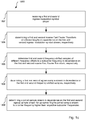
- Figure 1d shows a schematic sequence diagram 2800 to operate an OFDM-demodulator 2000 comprising steps 2802, 2804, 2806 and 2808.
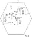
- FIG. 2 shows a schematic cellular radio communications network RCN.
- the cellular radio communications network RCN is a cellular network, wherein the first radio device BS establishes a radio cell C.
- the first radio device BS is a base station, a LTE eNodeB, a 5G transmission point, a WiFi access point, a remote radio head, RRH, or else.
- the first radio device BS is in particular suitable to serve the radio cell C and to connect user equipment in the sense of radio devices UE, UE_leg inside the radio cell C to the cellular radio communications network RCN.
- the first radio device BS is e.g. implemented as a stand-alone equipment.
- the second and third radio devices UE, UE_leg reside in the radio cell C and may be referred to as user equipment or machine equipment.
- the third radio device UE_leg is a LTE legacy device and fulfils 3GPP TS36.211 V14.00 Sep.2016, which is incorporated herein by reference.
- the first and second radio devices BS and UE comprise an OFDM-modulator 1000 and/or an OFDM-demodulator 2000, respectively.
- Many of the embodiments of this description allow operating the third radio device UE_leg in the cell C together with the first and second radio devices BS and UE.
- the first radio device BS comprises a memory M1, a processor P1, a radio module R1, and an antenna A1.
- the second radio device UE comprises a memory M2, the processor P2, a radio module R2, and an antenna A2.
- the third radio device UE_leg comprises a memory and 3, processor P3, a radio module are 3 and an antenna A1.
- the processors P1, P2, P3 are implemented using e.g. a DSP, FPGA, or the like or a combination thereof.
- the memory M1, M2, M3 is implemented using e.g. a RAM, ROM, DDR, Flash memory, or the like, or a combination thereof.
- the memory M1, M2, M3 stores e.g. computer readable instructions, thus instructions executable by the processor P1, P2, P3.
- the processor P1 processes data to be transmitted to the first and second radio device UE, UE_leg. The processing includes the steps necessary to fulfil the requirements set by the radio communications network RCN.
- NFV network functions virtualization
- a virtualized network function of e.g. a sender or receiver may include at least one virtual machine running different software and processes, on top of standard high-volume servers, switches and storage, or a cloud computing infrastructure, instead of having customized hardware appliances for each network function.
- a sender or receiver function may be implemented in a computer program using a computer program product embodied on a non-transitory computer readable medium for performing operations, wherein the computer program product comprises instructions, that when executed by a processor, perform the operations of the specific base station, eNodeB, network node, MME (Mobility Management Entity) and/or UE function.
- the computer program product comprises instructions, that when executed by a processor, perform the operations of the specific base station, eNodeB, network node, MME (Mobility Management Entity) and/or UE function.
- the methods described herein relate to digital signal processing and could thus be implemented using a processor like a digital signal processor, or the like. At least some of the functions relate to baseband processing and could thus be implemented using a transceiver, e.g. a baseband transceiver.
- the radio module is e.g. a radio module, or a remotely located so called RRH (Remote Radio Head).
- the constellation with a RRH is often used in connection with a so called NFV (Network Functions Virtualization) implementation, where a substantial part of processing is centralized in a server farm with a plurality of processors and a plurality of memory, and the radio specific up-conversion, the antenna and the digital-to-analog converter for data transmission in downlink to the user equipment and the analog-to-digital converter for receiving data from the user equipment in uplink is remotely located.
- the radio module is also called radio frontend and includes e.g. a digital-to-analog converter, a low-pass filter, a mixer, a local oscillator, a power amplifier and an antenna. The local oscillator generates the radio frequency which is mixed on the processed data.
- UE User equipment
- UE could be implemented as a device with a radio module, e.g. smartphone, tablet, smartwatch, sensor, actuator, equipment inside a vehicle, machine-to-machine equipment, or else.
- the radio communications network RCN is an OFDM (Orthogonal Frequency Division Multiplex) type network, e.g. UF-OFDM, F-OFDM, ZT-s-OFDM, P-OFDM, FC-OFDM, or another multi-carrier network, e.g. FS-FBMC, QAM-FBMC, etc.
- FS-FBMC e.g. FS-FBMC
- QAM-FBMC e.g. QAM - Quadrature Amplitude Modulation and/or QPSK - Quadrature Phase Shift Keying are used as modulation technique.
- the radio network RCN allocates resources using a scheduler and a time-frequency-resource grid, a t-f-resource.
- the t-f-resource includes time slots and associated subcarriers.
- the subcarriers are e.g. grouped in frequency subbands.
- a subband is assigned at least one subband parameter.
- a subband parameter is e.g. subcarrier spacing, other parameters are e.g. symbol duration, time overhead, time overhead type like zero postfix or cyclic prefix, windowing or filtering parameters.
- Dependent on the assigned or selected parameters the subband is characterized for a specific transmission type and is in particular suitable for the transmission of specific services.
- a service is e.g. eMBB (enhanced mobile broadband), mMTC (massive machine-type-communication), URLLC (ultra reliable low latency communication), vehicle-to-vehicle communication, voice, video, etc.
- An allocated physical resource block thus assigns a dedicated time slot associated with one or more subcarriers or a subband to a data packet.
- a physical resource block assigns one time slot to a subcarrier.
- a time slot is e.g. called a TTI (transmission time interval). The period of time could e.g. be one or more time slots.
- Data and control signals are transmitted using physical channels, e.g. physical downlink shared channel, physical downlink control channel, common control physical channel. Further data and control signals could be transmitted using broadcast channel, paging channel, multicast channel.
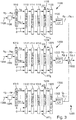
- FIG. 3 shows a schematic block diagram of the ODFM-modulator 1000 with a plurality of processing chains 1100, 1200, 1300.
- the processing chain 1100 is described in detail in the following, wherein the further processing chains are similar to the processing chain 1100 but may differ at least in the used respective block lengths and frequency offsets.
- a block 1106 determines the first ingress modulation-symbol stream a 0 ,...,a N-1 in dependence on a first ingress data stream 1108.
- the block 1106 may comprise an QAM-modulator (Quadrature Amplitude Modulation) and/or an QPSK-modulator (Quadrature Phase Shift Keying), a channel pre-coder, and/or further processing entities.
- QAM-modulator Quadrature Amplitude Modulation
- QPSK-modulator Quadrature Phase Shift Keying
- a serial to parallel converter 1110 converts the first ingress modulation-symbol stream a 0 ,...,a N-1 from a serial to a parallel symbol stream.
- the parallelized first ingress modulation-symbol stream a 0 ,...,a N-1 is applied to a subcarrier mapper 1112.
- a mapper 1114 maps reference symbols and/or synchronisation symbols to the modulation-symbol stream.
- the modulation-symbol stream determined by the mapper 1114 is applied to an inverse Fast Fourier Transform block 1118 to determine the inverse Fast Fourier Transform IFFT A in dependence on the the first ingress modulation-symbol stream a 0 ,...,a N-1 .
- a frequency shifter 1116 shifts the applied inverse Fast Fourier Transform IFFT A by the applied first frequency offset ⁇ f1 to determine a plurality of first frequence-shifted samples Sa in dependence on the first inverse Fast Fourier Transform IFFT A .
- the first frequency-shifted samples Sa are serialized by means of a parallel-to-serial converter 1120 and applied to a cyclic prefix (CP) inserter 1122 to determine the first egress sample stream d 0 ,...,d A-1 .
- the cyclic prefix inserter 1122 can be also omitted.
- the processing chains 1200, 1300 differ from the processing chain 1100 as described above in the following:
- the ingress data streams 1208 and 1308 and 1108 are mutually different with respect to their contents.
- the first block length A is also termed the main block length or the main FFT length.
- the block lengths N, M and P of the serial to parallel converters 1110, 1210 and 1310 are equal or smaller than the respective block length A, B, C of the corresponding inverse Fast Fourier Transform block 1118, 1218, 1318.
- the second radio device UE may only comprise processing chains with a high K-Factor, particularly a K-factor K greater than 1.
- Equation (3) provides the Fast Fourier Transform FFT_R of block length R with the parameter k.
- Equation (4) the right hand term is seperated into two components X_I and X_II each representing - as we will see - Fast Fourier Transforms.
- Equation (5) comprises a parameter transform from parameter k of equation (4) to the parameter 2*u.
- Equation (6) represents equation (5) in a rewritten form.
- Equations (5) and (6) provide two Fast Fourier Transforms XI(u) and XII(u) of a block length of R/2 in comparison with the Fast Fourier Transform of block length R in equations (3) and (4). Consequently, subcarrier orthogonality is maintained while FFT block lengths are used that comply with the K-factor scheme described in equation (1).
- Table 1 shows possible configurations for processing chains of the OFDM-modulator 1000 and the OFDM-demodulator 2000.
- Table 1 FFT Length Num N of PRBs K-Factor N * K Symbol Length in ⁇ s Bandwidth integration in LTE 20MHz 16 1 128 128 0,5 23,04MHz No 32 1 64 64 1,0 11,52MHz Yes 64 1 32 32 2,1 5,76MHz Yes 2 64 11,52MHz 3 96 17,28MHz 128 1 16 16 4,2 2,88MHz Yes 2 32 5,76MHz 3 48 8,64MHz 4 64 11,52MHz 5 80 14,40MHz 6 96 17,28MHz 256 1 8 8 8,33 1,44MHz Yes 2 16 2,88MHz 3 24 4,32MHz 4 32 5,76MHz 5 40 7,20MHz 6 48 8,64MHz 7 56 10,08MHz 8 64 11,52MHz 9 72 12,96MHz 10 80 14,40MHz 11 88 15,84MHz 12 96 17,28MHz 512 1 4 4 16,65 0,72MHz Yes 2 8 1,44MHz 3 12 2,16MHz 4 16 2,88MHz 5 20 3,60MHz 6 24 4,32MHz 7
- An adder 1902 adds the first, second and third egress sample streams d 0 ,...,d A-1 , e 0 ,...,e B-1 , f 0 ,...,f C-1 to a sum, namely the joined sample stream g 0 ,...,g A-1 .
- the joined sample stream g 0 ,...,g A-1 is applied to the respective radio module R1, R2 for further processing including e.g. digital-to-analog conversion and subsequently up-converted to a carrier frequency higher than respective subcarrier frequencies.
- the radio modules R1, R2 are possible.
- serial-to parallel-converters and the parallel-to-serial converters in figures 3 and 4 are arranged at an exemplary position. Of course these converters can be arranged at other positions to optimize the respective processing chain.
- FIG. 4 shows schematic block diagram of an OFDM-demodulator 2000 with a plurality of processing chains 2100, 2200, 2300.
- the processing chain 2100 is described in detail in the following, wherein the further processing chains are similar to the processing chain 2100.
- a cyclic prefix remover 2108 removes a cyclic prefix CP.
- the cyclic prefix remover 2108 can also be omitted.
- the frequency shifter 2110 back-shifts the down-converted sample stream h 0 ,...,h A-1 ,... not comprising the cyclic prefix in dependence on the supplied first frequency offset ⁇ f1.
- the frequency shifter 2110 determines the first ingress sample stream i 0 ,...,i A-1 , which is parallelized by a serial-to-parallel converter 2112.
- a forward Fast Fourier Transform block 2114 determines the forward Fast Fourier Transform FFT A of the first block size A in dependence on the parallelised ingress sample stream i 0 ,...,i A-1 .
- a demapper 2116 demaps the subcarriers.
- a parallel-to-serial converter 2118 of block length N determines the first egress demodulation-symbol stream m 0 ,...,m N-1 in dependence on the first forward Fast Fourier Transform FFT A .
- a channel estimator 2120 determines a channel estimate 2122 in dependence on reference symbols contained in the first egress demodulation-symbol stream m 0 ,...,m N-1 .
- An equalizer 2124 determines an equalized egress modulation-symbol stream 2126 in dependence on the first egress demodulation-symbol stream m 0 ,...,m N-1 and in dependence on the channel estimate 2122.
- the channel estimates 2122 and 2222 can be exchanged, wherein for example the estimator 2120 receives the channel estimate 2222.
- a block 2128 determines an egress data stream 2130 in dependence on the equalized egress demodulation-symbol stream 2126.
- the channel estimator 2120 and the equalizer 2124 are only examplary and may comprise other taps regarding the respective input and output symbol streams.
- the block 2128 may comprise an QAM-demodulator (Quadrature Amplitude Modulation) and/or an QPSK-demodulator (Quadrature Phase Shift Keying), a channel de-coder, and/or further processing entities.
- the egress data stream 2130 equals the ingress data stream 1108.
- a correlator 2132 detects a synchronization symbol in the first egress demodulation-symbol stream m 0 ,...,m N-1 and determines a synchronisation state 2134.
- the processing chains 2200, 2300 differ from the processing chain 2100 as described above in the following:
- the egress data streams 2130 and 2230 and 2330 are mutually different with respect to their contents.
- the second and third block lengths B, C of the second and third forward Fast Fourier Transform FFT B , FFT C multiplied with the K-factor equals the main block length A.
- FIG. 5 shows a schematic block diagram of the ODFM-modulator 1000.
- the first processing chain 1100 is operated with the main block length A of 2048.
- the second and fourth processing chains 1200 and 1400 are operated with the same block length B of 128.
- the third processing chain 1300 is operated with the block length C of 64.
- the frequency shifters 1216, 1316 and 1416 apply respective frequency offsets ⁇ f2, ⁇ f3 and ⁇ f4.
- Figure 6 shows schematic block diagram of an OFDM-demodulator 2000.
- the frequency shifter 2110 no frequency back-shift is applied on the down-converted sample stream h 0 ,...,h A-1 ,... in the first processing chain 2100.
- Frequency shifters 2210, 2310 and 2410 back-shift the down-converted sample stream h 0 ,...,h A-1 ,... by the respective frequency offsets ⁇ f2, ⁇ f3 and ⁇ f4 to determine the respective ingress sample streams.
- Figure 7 shows a schematic representation of the joined modulation-symbol stream g 0 ,...,g A-1 of figure 5 .
- different OFDM symbol lengths of OFDM_2048 and OFDM_128 can be realized by means of the proposed OFDM-modulator 1000 and the OFDM-demodulator 2000.
- the numerology in the sense of frequency offsets and block length on the respective subcarrier or subcarrier block may change. Therefore, numerology changes from one (largest) OFDM-symbol to another is possible.
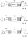
- Figure 9 shows schematically the inverse Fast Fourier Transform block 1218 with the block length B of 128 to generate an OFDM-symbol length of 4,2 ⁇ s (omitting cyclic prefix).
- the K-Factor corresponding to the block 1218 is 16.
- Figure 10 shows schematically the inverse Fast Fourier Transform block 1318 with the block length C of 64 to generate an OFDM-symbol length of 2, 1 ⁇ s (omitting cyclic prefix).
- the K-Factor corresponding to the block 1318 is 32.
- Figure 11 shows a schematic time frequency representation of the joined modulation-symbol stream g 0 ,...,g A-1 .
- the frequency offset ⁇ f2 which is applied to the frequency shifter 1216.
- the DC carrier is the reference for all frequency offsets ⁇ f and has an exemplary value of Zero Hz.
- To determine the frequency offset ⁇ f2 the number of physical resource blocks RBs, namely 32, is multiplied with the number of subcarriers per resource block RB, namely 12, with an additional subcarrier SC of one. The result is multiplied with the subcarrier spacing SCS, namely 15 kHz. Therefore the frequency offset ⁇ f2 is calculated according to the following equation (7).
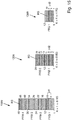
- FIG. 12 shows a schematic representation of IFFT processing formats. Exemplary input modulation-symbols of the inverse Fast Fourier Transform blocks 1118, 1218 and 1318 of figure 5 are shown.
- Figure 13 shows a schematic time-frequency representation of a primary synchronisation signal PSS and a secondary synchronisation signal SSS.
- the synchronisation signals PSS, SSS can be determined according to 3GPP 36.211 section 6.11, which is incorporated by reference, and are mapped to 62 subcarriers around the DC carrier to the third and seventh of the (largest) OFDM-symbol of the main processing chain 1100 with main block size A, respectively.
- mappers 1114, 1214, 1314 it is determined an inverse Fast Fourier Transform IFFT of a synchronization sequence SS with the first block size A.
- the inverse Fast Fourier Transform IFFT of the synchronization sequence SS is repeated across the available bandwidth according to frequency ranges PSS_A and PSS_B, SSS_A and SSS_B, respectively.
- the demappers 2116, 2216, 2316 it is determined at least a component PSS_128_1, PSS_128_2, SSS_128_1, SSS_128_2 of the synchronization signal PSS, SSS, which has been modulated with the first block length A, in dependence on the second egress demodulation-symbol stream n 0 ,...,n M-1 .
- the shown components PSS_128_1, PSS_128_2, SSS_128_1, SSS_128_2 can be seen at the side of the OFDM-demodulator 2000 in the second egress demodulation-symbol stream with the second processing chain 2200 operating with the block length B of 128. Therefore the proposed mapping scheme makes available synchronisation information for every processing chain on the side of the OFDM-demodulator 2000. For processing chains with the K-Factor larger than one the synchronisation symbol is split in symbols of reduced length.
- Figure 14 shows a schematic time-frequency representation of synchronisation signals PSS, SSS.
- the synchronisation signals PSS, SSS are mapped to 72 subcarriers around the DC carrier to the first and seventh OFDM-symbol of the main processing chain 1100 with main block size A, respectively.
- Figure 15 shows an exemplary reference symbol allocation scheme for operating the mappers 1112, 1212, 1312 and the demappers 2116, 2216, 2316.
- the OFDM-modulator 1000 and the OFDM-demodulator 2000 operate with a physical resource block length of 12 subcarriers.
- a first plurality of reference symbols RS are inserted into the first ingress modulation-symbol stream a 0 ,...,a N-1 with a spacing d1 between neighboring reference symbols RS of five subcarriers.
- a second plurality of reference symbols RS is inserted into the second ingress modulation-symbol stream b 0 ,...,b M-1 with a spacing d2 between neighboring reference symbols RS of two subcarriers.
- the processing chain 2100 is configured to determine a first plurality of reference symbols RS from the first egress demodulation-symbol stream m 0 ,...,m N-1 with the spacing d1 between neighboring reference symbols RS of five subcarriers.
- the processing chain 2200 on the other hand is configured to determine a second plurality of reference symbols RS from the second egress demodulation-symbol stream n 0 ,...,n M-1 with the spacing d2 between neighboring reference symbols RS of two subcarriers.
- the reference symbols system of 3GPP 36.211 which is incorporated herein by reference, can be used for the first processing chain 1100, wherein reference symbols are positioned as a function of frequency, time, antenna port and cell ID.
- the proposed scheme comprises a shift by 3 subcarriers between the positions 0 and 4 in the respective subcarriers. Between adjacent cells the reference symbols are shifted. According to the example in figure 15 the reference symbols are shifted by one position in comparison with the proposed scheme in 3GPP 36.211.
- Figure 16 shows an exemplary reference symbol allocation scheme.
- the OFDM-modulator 1000 and the OFDM-demodulator 2000 operate with a physical resource block length of 2 ⁇ X subcarriers, in the example a physical resource block PRB comprises 16 subcarriers.
- the processing chain 1100 is configured to insert a first plurality of reference symbols RS into the first ingress modulation-symbol stream a 0 ,...,a N-1 at each 2 ⁇ Z subcarrier position.
- the second processing chain 1200 with a K-Factor of 2 is configured to insert a second plurality of reference symbols RS into the second ingress modulation-symbol stream b 0 ,...,b M-1 at each 2 ⁇ Z subcarrier positions and at further positions between the 2 ⁇ Z subcarrier positions, namely positions 4 and 12.
- the first processing chain 2100 of the OFDM-demodulator 2000 is configured to determine a first plurality of reference symbols RS from the first egress demodulation-symbol stream m 0 ,...,m N-1 at each 2 ⁇ Z subcarrier position.
- the second processing chain 2200 with a K-Factor of 2 is configured to determine a second plurality of reference symbols RS from the second egress demodulation-symbol stream n 0 ,...,n M-1 at each 2 ⁇ Z subcarrier positions and at further positions between the 2 ⁇ Z subcarrier positions, namely positions 4 and 12.
- Figure 17 shows an exemplary reference symbol allocation scheme. With difference to figure 16 a number of 16 reference symbols RS is distributed in frequency direction. However, the same distribution scheme along the different K-Factor systems and the respective processing chains applies, particularly providing at each 2 ⁇ Z subcarrier position across the respective bandwidth a reference symbol and increase the reference symbol density with rising K-Factor by filling the gaps between neighbouring 2 ⁇ Z subcarrier positions with further reference symbols RS.
- Figure 18 shows schematically a downlink transmission scheduling scheme.
- a downlink transmission is scheduled by the first radio device BS.
- a downlink transmission is scheduled by transmitting in a step 18_2 a downlink scheduling decision comprising at least an indication of the frequency offset ⁇ f and an indication of the block length for the respective fourier transform.
- a step 18_3 downlink data is modulated with the scheduled frequency offset and block length.
- the modulated downlink data is transmitted to the second radio device UE.
- the second radio device UE can then receive and demodulate the downlink data in a step 18_5 by back shifting the respective samples with the scheduled frequency offset ⁇ f and determining a forward Fourier transform FFT with the scheduled block length.
- Figure 19 shows schematically an uplink transmission scheduling scheme.
- the first radio device BS schedules an uplink transmission in a step 19_1.
- a scheduling decision indicating at least a pair of the frequency offset ⁇ f and the block length for uplink data is transmitted to the second radio device UE in a step 19_2.
- the second radio device UE modulates in a step 19_3 the uplink data in dependence on the uplink scheduling decision.
- the modulated uplink data is transmitted to the first radio device BS.
- the uplink data is demodulated in dependence on the scheduled uplink transmission.
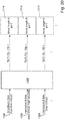
- Figure 20 shows a schematic block diagram for operating a multi-service device for transmission.
- a subband used is assigned to a K-factor. Further subband parameters comprise e.g. subcarrier spacing, other parameters are e.g. symbol duration, time overhead, time overhead type like zero postfix or cyclic prefix, windowing or filtering parameters.
- Dependent on the assigned or selected K-factor K the subband is characterized for a specific transmission type and is in particular suitable for the transmission of specific services.
- a service 1108 is e.g. eMBB (enhanced mobile broadband).
- a service 1208 is e.g. mMTC (massive machine-type-communication).
- a service 1308 is URLLC (ultra reliable low latency communication.
- Futher services comprise vehicle-to-vehicle communication, voice, video, etc.
- An allocated resource block thus assigns a dedicated time slot associated with one or more subcarriers or a subband with the respective K-factor K to a data packet of the corresponding service.
- a block 1500 distributes the data of the services 1108 to 1308 to the respective ingress symbol streams.
- Figure 21 shows a schematic block diagram for operating the multi-service device for reception.
- Data of the services 1108 to 1308 is reconstructed by means of a block 2500 which receives the egress demodulation-symbol streams m 0 ,...,m N-1 , n 0 ,...,n M-1 , O 0 ,...,O P-1 .
- processors may be provided through the use of dedicated hardware as well as hardware capable of executing software in association with appropriate software.
- the functions may be provided by a single dedicated processor, by a single shared processor, or by a plurality of individual processors, some of which may be shared.
- explicit use of the term "processor” or “controller” should not be construed to refer exclusively to hardware capable of executing software, and may implicitly include, without limitation, digital signal processor (DSP) hardware, network processor, application specific integrated circuit (ASIC), field programmable gate array (FPGA), read only memory (ROM) for storing software, random access memory (RAM), and non volatile storage.
- DSP digital signal processor
- ASIC application specific integrated circuit
- FPGA field programmable gate array
- ROM read only memory
- RAM random access memory
- any switches shown in the FIGS. are conceptual only. Their function may be carried out through the operation of program logic, through dedicated logic, through the interaction of program control and dedicated logic, or even manually, the particular technique being selectable by the implementer as more specifically understood from the context.
- any block diagrams herein represent conceptual views of illustrative circuitry embodying the principles of the invention.
- any flow charts, flow diagrams, state transition diagrams, pseudo code, and the like represent various processes which may be substantially represented in computer readable medium and so executed by a computer or processor, whether or not such computer or processor is explicitly shown.
Landscapes
- Engineering & Computer Science (AREA)
- Computer Networks & Wireless Communication (AREA)
- Signal Processing (AREA)
- Mobile Radio Communication Systems (AREA)
Abstract
Description
- The present disclosure is directed to an OFDM-modulator, an OFDM-demodulator, a method to operate an OFDM-modulator, and a method to operate an OFDM-demodulator.
- Evolving radio communications standards like 5G permit an efficient multi-cell / multi-TP (transmission point) support of mixed numerologies, namely mixed subcarrier configurations. 5G in general and specifically 3GPP New Radio targets multi-service support within one carrier. As the different service use cases are very different from each other, they motivate a variety of OFDM basic parameter sets, so called numerologies.
- An object of the disclosure is to propose an OFDM-modulator for operating in a radio device of a cellular radio communications network, wherein the OFDM-modulator comprises a processor and a memory being configured to: receive a first and second ingress modulation-symbol stream; determine a first and second inverse Fast Fourier Transform of different block lengths in dependence on the first and second ingress modulation-symbol stream, respectively; determine first and second frequency-shifted samples of different frequency offsets to a subcarrier frequency in dependence on the first and second inverse Fast Fourier Transform, respectively; determine a first and second egress sample stream in dependence on the first and second frequency-shifted samples, respectively; and determine a joined sample stream in dependence on the first and second frequency-shifted samples for up-converting the joined sample stream to a carrier frequency higher than respective subcarrier frequencies.
- A plurality of numerologies in the sense of different block lengths may exist in the OFDM-symbol of the main block length. This coexistence of different numerologies allows partially shorter symbol lengths with a corresponding increase in usable bandwidth. As the shorter symbols are mapped into longer symbols, there is no loss of transmission capacity. A new degree of freedom for scheduling radio transmissions is therefore available. Moreover a plurality of quality of service classes can be supported and increased performance requirements can be fulfilled.
- According to an advantageous embodiment the second block length of the second inverse Fast Fourier Transform multiplied with an integer factor equals the first block length of the first inverse Fast Fourier Transform. This allows combining the plurality of modulation/demodulation systems with different FFT/IFFT lengths on a fixed subcarrier grid. Moreover, this scheme maintains orthogonality with respect to the basic subcarrier grid.
- According to an advantageous embodiment the first block length equals 2048. This allows operating and scheduling LTE legacy devices in the same radio cell with radio devices comprising the proposed OFDM-modulator and/or OFDM-demodulator. This scheme therefore supports a migration from 4G/LTE to 5G.
- According to an advantageous embodiment the processor and the memory are further configured to: repeat the synchronization sequence across the available bandwidth as a synchronization signal. Therefore, synchronisation across a plurality of systems with different block lengths and different frequency offsets is feasible.
- According to an advantageous embodiment the processor and memory are further configured to: operate with a physical resource block length of 2^X subcarriers; insert a first plurality of reference symbols into the first ingress modulation-symbol stream at each 2^Z subcarrier position; insert a second plurality of reference symbols into the second ingress modulation-symbol stream at each 2^Z subcarrier positions and at further positions derived via a single shift operation of the 2^Z grid positions. Consequently, the reference symbols can be seen and exploited in systems of different FFT/IFFT length and different frequency offset. Therefore, channel estimation benefits.
- According to an advantageous embodiment the processor and memory are further configured to: operate with a physical resource block length of 12 subcarriers; insert a first plurality of reference symbols into a first ingress modulation-symbol of a slot at each sixth subcarrier; insert a second plurality of reference symbols into a fifth ingress modulation-symbol of a slot at each third subcarrier. This allows the mentioned LTE backward compatibility for operating the legacy LTE device in the same radio cell with radio devices comprising the proposed OFDM-modulator and/or OFDM-demodulator. This reference symbols scheme is compatible with LTE/4G.
- According to another aspect it is proposed an OFDM-demodulator for operating in a device of a cellular radio communications network, wherein the OFDM-demodulator comprises a processor and a memory being configured to: receive a down-converted sample stream; determine a first and second ingress sample stream of the down-converted sample stream of different block lengths and of different frequency offsets to a subcarrier frequency, respectively; determine a first and second forward Fast Fourier Transform of the different block length in dependence on the first and second ingress sample stream; determine a first and second egress demodulation-symbol stream in dependence on the first and second forward Fast Fourier Transform, respectively.
- A plurality of numerologies in the sense of different block lengths may exist in a single OFDM-symbol of the main block length. This coexistence of different numerologies allows partially shorter symbol lengths with a corresponding increase in occupied bandwidth. As the shorter symbols are mapped into longer symbols, there is no loss of transmission capacity. A new degree of freedom is therefore available for scheduling radio transmissions. Moreover a plurality of quality of service classes can be supported and increased performance requirements with regard to shorter latency can be fulfilled.
- According to an advantageous embodiment the second block length of the second forward Fast Fourier Transform multiplied with an integer factor equals the first block length of the first forward Fast Fourier Transform. This allows combining the plurality of modulation/demodulation systems with different FFT/IFFT lengths on a fixed subcarrier grid. Moreover, this scheme maintains orthogonality with respect to the basic subcarrier grid.
- According to an advantageous embodiment the first block length equals 2048. This allows operating and scheduling LTE legacy devices in the same radio cell with radio devices comprising the proposed OFDM-modulator and/or OFDM-demodulator. This scheme therefore supports a migration from 4G/LTE to 5G.
- According to an advantageous embodiment at least a component of a synchronization signal is determined in dependence on the second egress demodulation-symbol stream. Therefore, synchronisation across a plurality of systems with different FFT lengths and different frequency offsets is feasible.
- According to an advantageous embodiment the processor and memory are further configured to: operate with a physical resource block length of 2^X subcarriers; determine a first plurality of reference symbols from the first egress demodulation-symbol stream at each 2^Z subcarrier position; determine a second plurality of reference symbols from the second egress demodulation-symbol stream at each 2^Z subcarrier positions and at further positions between the 2^Z subcarrier positions derived via a single shift operation of the 2^Z grid positions. Consequently, the reference symbols can be seen and exploited in systems of different FFT length and different frequency offset. Therefore, channel estimation benefits.
- According to an advantageous embodiment the processor and memory are further configured to: operate with a physical resource block length of 12 subcarriers; determine a first plurality of reference symbols from egress demodulation-symbols of a slot at each sixth subcarrier; determine a second plurality of reference symbols from egress demodulation-symbols of a slot at each third subcarrier. This allows the mentioned LTE backward compatibility for operating the legacy LTE device in the same radio cell with radio devices comprising the proposed OFDM-modulator and/or OFDM-demodulator. This reference symbols scheme is compatible with LTE/4G.
- A further object of the description is to propose a method to operate an OFDM-modulator.
- A further object of the description is to propose a method to operate an OFDM-demodulator.
-
-
Figure 1a, 1b ,3 to 6 show a schematic block diagram of an ODFM-modulator or an OFDM-demodulator, respectively; -
Figures 1c ,1d show a schematic sequence diagram, respectively; -
Figure 2 shows a schematic cellular radio communications network; -
Figure 7 ,11 shows a schematic representation of a joined modulation-symbol stream, respectively; -
Figure 8, 9 and 10 show schematically an inverse Fast Fourier Transform block, respectively; -
Figure 12 shows a schematic representation of IFFT processing formats, respectively; -
Figure 13 ,14 show a schematic time-frequency representation of synchronisation signals, respectively; -
Figure 15 ,16 ,17 show an exemplary reference symbol allocation scheme, respectively; -
Figure 18 ,19 show schematically a scheduling scheme, respectively; and -
Figure 20 ,21 show a schematic block diagram for operating a multi-service device, respectively. -
Figure 1a shows a schematic block diagram of an OFDM-modulator 1000 with afirst processing chain 1100 and asecond processing chain 1200. Afirst block 1102 of thefirst processing chain 1100 receives a first ingress modulation-symbol stream a0,...,aN-1 and determines a first inverse Fast Fourier Transform IFFTA of a first block length A and of a first frequency offset Δf1 to a subcarrier frequency. Thefirst block 1102 assigns the individual modulation-symbols to a set of resource blocks occupying one or more subbands. When referring to a block length of an FFT and/or IFFT the terms FFT length and IFFT length can be used. A first inverse Fast Fourier Transform is determined from the first ingress modulation-symbol stream a0,...,aN-1. Then first frequency-shifted samples Sa are determined by frequency-shifting the first inverse Fast Fourier Transform of the first ingress modulation-symbol stream a0,...,aN-1 by the first frequency offset Δf1. As a result, a whole subband is used by the first inverse Fast Fourier Transform. Asecond block 1104 of thefirst processing chain 1100 receives the first frequency-shifted samples Sa and determines a first egress sample stream d0,...,dA-1. - A
first block 1202 of thesecond processing chain 1200 receives a second ingress modulation-symbol stream b0,...,bM-1 and determines second frequency-shifted samples Sb of a second block length B, different from the first block length A, and of a second frequency offset Δf2 to the subcarrier frequency. Thefirst block 1202 assigns the individual modulation-symbols to a set of resource blocks occupying one or more subbands. An inverse Fast Fourier Transform is determined from the second ingress modulation-symbol stream b0,...,bM-1. Then the second frequency-shifted samples Sb are determined by frequency-shifting the inverse Fast Fourier Transform of the second ingress modulation-symbol stream b0,...,bM-1 by the second frequency offset Δf2. As a result, a whole subband is used by the second inverse Fast Fourier Transform IFFTB. Asecond block 1204 of thesecond processing chain 1200 receives the second frequency-shifted samples Sb and determines a second egress sample stream e0,...,eB-1. Ablock 1900 determines a joined sample stream g0,...,gA-1 in dependence on the first and second egress sample streams d0,...,dA-1, e0,...,eB-1 for up-converting the joined sample stream g0,...,gA-1 to a carrier frequency higher than respective subcarrier frequencies. - According to this description a modulation-symbol represents a complex value. A modulation-symbol stream represents a plurality of modulation-symbols in a sequence in time. The same applies to a sample stream. Moreover, the modulation-symbol is processed in a modulator. The demodulation-symbol is processed in a demodulator.
- The wording ingress and egress have the following meaning: The ingress symbol stream, for example the ingress modulation-symbol stream, is located toward an input side of the respective processing entity, for example a processing chain. The egress symbol stream is located toward an output side of the processing entity, for example a processing chain. Therefore, the ingress symbol stream may differ from an actual input symbol stream at the beginning of the processing chain. The same applies to the egress symbol stream. So, when referring to a symbol stream this symbol stream refers to time or frequency domain.
- Moreover the wording block length of a Fourier Transform can be used interchangeably with the wording length of a Fourier Transform or FFT length or IFFT length.
-
Figure 1b shows schematic block diagram of an OFDM-demodulator 2000. A down-converted sample stream h0,...,hA-1,... is received from an A/D-converter of the respective radio module R1, R2. Ablock 2102 of afirst processing chain 2100 determines a first ingress sample stream i0,...,iA-1 of the first block length A in dependence on the down-converted sample stream h0,...,hA-1,... and in dependence on the first frequency offset Δf1 to the subcarrier frequency, wherein the first ingress sample stream i0,...,iA-1 is back shifted in frequency by the first frequency offset Δf1. Ablock 2104 determines a first forward Fast Fourier - Transform FFTA of the first block length A in dependence on the first ingress sample stream i0,...,iA-1. A
block 2106 determines a first egress demodulation-symbol stream m0,...,mN-1 in dependence on the first forward Fast Fourier Transform FFTA. - A
block 2202 of asecond processing chain 2200 determines a second ingress sample stream k0,...,kB-1 in dependence on the down-converted sample stream h0,...,hA-1,... of the second block length B and in dependence on the second frequency offset Δf2 to the subcarrier frequency, wherein the second ingress sample stream k0,...,kB-1 is back-shifted in frequency by the second frequency offset Δf2. Ablock 2204 determines a second forward Fast Fourier Transform FFTB of the second block length B in dependence on the second ingress sample stream k0,...,kB-1. Ablock 2206 determines a second egress demodulation-symbol stream n0,...,nM-1 in dependence on the second forward Fast Fourier Transform FFTB. -
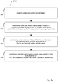
Figure 1c shows a schematic sequence diagram 1800 to operate the ODFM-modulator 1000 comprisingsteps -
Figure 1d shows a schematic sequence diagram 2800 to operate an OFDM-demodulator 2000 comprisingsteps -
Figure 2 shows a schematic cellular radio communications network RCN. The cellular radio communications network RCN is a cellular network, wherein the first radio device BS establishes a radio cell C. The first radio device BS is a base station, a LTE eNodeB, a 5G transmission point, a WiFi access point, a remote radio head, RRH, or else. The first radio device BS is in particular suitable to serve the radio cell C and to connect user equipment in the sense of radio devices UE, UE_leg inside the radio cell C to the cellular radio communications network RCN. The first radio device BS is e.g. implemented as a stand-alone equipment. The second and third radio devices UE, UE_leg reside in the radio cell C and may be referred to as user equipment or machine equipment. - The third radio device UE_leg is a LTE legacy device and fulfils 3GPP TS36.211 V14.00 Sep.2016, which is incorporated herein by reference. The first and second radio devices BS and UE comprise an OFDM-
modulator 1000 and/or an OFDM-demodulator 2000, respectively. Many of the embodiments of this description allow operating the third radio device UE_leg in the cell C together with the first and second radio devices BS and UE. - The first radio device BS comprises a memory M1, a processor P1, a radio module R1, and an antenna A1. The second radio device UE comprises a memory M2, the processor P2, a radio module R2, and an antenna A2. The third radio device UE_leg comprises a memory and 3, processor P3, a radio module are 3 and an antenna A1. The processors P1, P2, P3 are implemented using e.g. a DSP, FPGA, or the like or a combination thereof. The memory M1, M2, M3 is implemented using e.g. a RAM, ROM, DDR, Flash memory, or the like, or a combination thereof. The memory M1, M2, M3 stores e.g. computer readable instructions, thus instructions executable by the processor P1, P2, P3. The processor P1 processes data to be transmitted to the first and second radio device UE, UE_leg. The processing includes the steps necessary to fulfil the requirements set by the radio communications network RCN.
- At least parts of the above described cellular radio communications network RCN including sender and/or receiver of the first radio device BS could be implemented using network functions virtualization (NFV). NFV is a network architecture that makes use of technologies of computer virtualization. Entire network equipment like sender or receiver or parts thereof or part of their functions can be virtualized using software building blocks that may connect, or interact, to create communication services. A virtualized network function of e.g. a sender or receiver may include at least one virtual machine running different software and processes, on top of standard high-volume servers, switches and storage, or a cloud computing infrastructure, instead of having customized hardware appliances for each network function. As such a sender or receiver function may be implemented in a computer program using a computer program product embodied on a non-transitory computer readable medium for performing operations, wherein the computer program product comprises instructions, that when executed by a processor, perform the operations of the specific base station, eNodeB, network node, MME (Mobility Management Entity) and/or UE function.
- The methods described herein relate to digital signal processing and could thus be implemented using a processor like a digital signal processor, or the like. At least some of the functions relate to baseband processing and could thus be implemented using a transceiver, e.g. a baseband transceiver. The radio module is e.g. a radio module, or a remotely located so called RRH (Remote Radio Head). The constellation with a RRH is often used in connection with a so called NFV (Network Functions Virtualization) implementation, where a substantial part of processing is centralized in a server farm with a plurality of processors and a plurality of memory, and the radio specific up-conversion, the antenna and the digital-to-analog converter for data transmission in downlink to the user equipment and the analog-to-digital converter for receiving data from the user equipment in uplink is remotely located. The radio module is also called radio frontend and includes e.g. a digital-to-analog converter, a low-pass filter, a mixer, a local oscillator, a power amplifier and an antenna. The local oscillator generates the radio frequency which is mixed on the processed data. The aforementioned modules/functions could be placed in serial order. Some modules might be not be used or replaced by others dependent on the technology used. For MIMO or massive MIMO some modules need to be duplicated, e.g. a plurality of antennas is used instead of one and corresponding amplifiers, etc. Additional modules might be added for performing und/or supporting specific functions as e.g. beamforming, CoMP (coordinated multipoint), eICIC (enhanced inter-cell interference control), or the like. User equipment (UE) could be implemented as a device with a radio module, e.g. smartphone, tablet, smartwatch, sensor, actuator, equipment inside a vehicle, machine-to-machine equipment, or else. The radio communications network RCN is an OFDM (Orthogonal Frequency Division Multiplex) type network, e.g. UF-OFDM, F-OFDM, ZT-s-OFDM, P-OFDM, FC-OFDM, or another multi-carrier network, e.g. FS-FBMC, QAM-FBMC, etc. E.g. QAM - Quadrature Amplitude Modulation and/or QPSK - Quadrature Phase Shift Keying are used as modulation technique. The radio network RCN allocates resources using a scheduler and a time-frequency-resource grid, a t-f-resource. The t-f-resource includes time slots and associated subcarriers. The subcarriers are e.g. grouped in frequency subbands. A subband is assigned at least one subband parameter. A subband parameter is e.g. subcarrier spacing, other parameters are e.g. symbol duration, time overhead, time overhead type like zero postfix or cyclic prefix, windowing or filtering parameters. Dependent on the assigned or selected parameters the subband is characterized for a specific transmission type and is in particular suitable for the transmission of specific services. A service is e.g. eMBB (enhanced mobile broadband), mMTC (massive machine-type-communication), URLLC (ultra reliable low latency communication), vehicle-to-vehicle communication, voice, video, etc. An allocated physical resource block thus assigns a dedicated time slot associated with one or more subcarriers or a subband to a data packet. A physical resource block assigns one time slot to a subcarrier. A time slot is e.g. called a TTI (transmission time interval). The period of time could e.g. be one or more time slots. Data and control signals are transmitted using physical channels, e.g. physical downlink shared channel, physical downlink control channel, common control physical channel. Further data and control signals could be transmitted using broadcast channel, paging channel, multicast channel.
-
Figure 3 shows a schematic block diagram of the ODFM-modulator 1000 with a plurality ofprocessing chains processing chain 1100 is described in detail in the following, wherein the further processing chains are similar to theprocessing chain 1100 but may differ at least in the used respective block lengths and frequency offsets. Ablock 1106 determines the first ingress modulation-symbol stream a0,...,aN-1 in dependence on a firstingress data stream 1108. Theblock 1106 may comprise an QAM-modulator (Quadrature Amplitude Modulation) and/or an QPSK-modulator (Quadrature Phase Shift Keying), a channel pre-coder, and/or further processing entities. A serial to parallelconverter 1110 converts the first ingress modulation-symbol stream a0,...,aN-1 from a serial to a parallel symbol stream. The parallelized first ingress modulation-symbol stream a0,...,aN-1 is applied to asubcarrier mapper 1112. Amapper 1114 maps reference symbols and/or synchronisation symbols to the modulation-symbol stream. The modulation-symbol stream determined by themapper 1114 is applied to an inverse FastFourier Transform block 1118 to determine the inverse Fast Fourier Transform IFFTA in dependence on the the first ingress modulation-symbol stream a0,...,aN-1. Afrequency shifter 1116 shifts the applied inverse Fast Fourier Transform IFFTA by the applied first frequency offset Δf1 to determine a plurality of first frequence-shifted samples Sa in dependence on the first inverse Fast Fourier Transform IFFTA. The first frequency-shifted samples Sa are serialized by means of a parallel-to-serial converter 1120 and applied to a cyclic prefix (CP)inserter 1122 to determine the first egress sample stream d0,...,dA-1. Thecyclic prefix inserter 1122 can be also omitted. - The
processing chains processing chain 1100 as described above in the following: Theingress data streams converters Fourier Transform block - Given the largest block length of the fourier transform in the sense of the main block length A, each processing chain has to fulfil the following equation (1) with a FFT block length bl and the corresponding K-factor K. From equation (1) it is apparent that the K-Faktor K always equals to a power of two.

- For cellular radio communications network RCN with the main block length A of 2048 also legacy LTE devices can be supported. In this case the subcarrier spacing f0 providing a fixed subcarrier spacing grid for all of the other processing chains is 15 kHz. Of course, the main block length A can be chosen differently, however loosing compatibility with legacy LTE devices. The sample time Ts is the same for all systems and forms together with a basic subcarrier spacing f0 the fixed elementary parameters of all configurations. The K-factor K for each FFT length can then be determined according to equation (2).

- For applications with a demand for low energy consumption and short symbol rates, the second radio device UE may only comprise processing chains with a high K-Factor, particularly a K-factor K greater than 1.
- The following equations (3) to (6) show that the modulation and demodulation scheme proposed in this description still provides that the subcarriers are orthogonal. Equation (3) provides the Fast Fourier Transform FFT_R of block length R with the parameter k. In equation (4) the right hand term is seperated into two components X_I and X_II each representing - as we will see - Fast Fourier Transforms. Equation (5) comprises a parameter transform from parameter k of equation (4) to the
parameter 2*u. Equation (6) represents equation (5) in a rewritten form. Equations (5) and (6) provide two Fast Fourier Transforms XI(u) and XII(u) of a block length of R/2 in comparison with the Fast Fourier Transform of block length R in equations (3) and (4). Consequently, subcarrier orthogonality is maintained while FFT block lengths are used that comply with the K-factor scheme described in equation (1).


- The following table 1 shows possible configurations for processing chains of the OFDM-
modulator 1000 and the OFDM-demodulator 2000.Table 1 FFT Length Num N of PRBs K-Factor N * K Symbol Length in µs Bandwidth integration in LTE 20MHz 16 1 128 128 0,5 23,04MHz No 32 1 64 64 1,0 11,52MHz Yes 64 1 32 32 2,1 5,76MHz Yes 2 64 11,52MHz 3 96 17,28MHz 128 1 16 16 4,2 2,88MHz Yes 2 32 5,76MHz 3 48 8,64MHz 4 64 11,52MHz 5 80 14,40MHz 6 96 17,28MHz 256 1 8 8 8,33 1,44MHz Yes 2 16 2,88MHz 3 24 4,32MHz 4 32 5,76MHz 5 40 7,20MHz 6 48 8,64MHz 7 56 10,08MHz 8 64 11,52MHz 9 72 12,96MHz 10 80 14,40MHz 11 88 15,84MHz 12 96 17,28MHz 512 1 4 4 16,65 0,72MHz Yes 2 8 1,44MHz 3 12 2,16MHz 4 16 2,88MHz 5 20 3,60MHz 6 24 4,32MHz 7 28 5,04MHz 8 32 5,76MHz 9 36 6,48MHz 10 40 7,20MHz 11 44 7,92MHz 12 48 8,64MHz 13 52 9,36MHz 14 56 10,08MHz 15 60 10,80MHz 16 64 11,52MHz 17 68 12,24MHz 18 72 12,96MHz 19 76 13,68MHz 20 80 14,40MHz 21 84 15,12MHz 22 88 15,84MHz 23 92 16,56MHz 24 96 17,28MHz 25 100 18,00MHz 1024 1 2 2 33,3 0,36MHz Yes 2 4 0,72MHz 3 6 1,08MHz 4 8 1,44MHz 5 10 1,80MHz 6 12 2,16MHz 7 14 2,52MHz 8 16 2,88MHz 9 18 3,24MHz 10 20 3,60MHz 11 22 3,96MHz 12 24 4,32MHz 13 26 4,68MHz 14 28 5,04MHz 15 30 5,40MHz 16 32 5,76MHz 17 34 6,12MHz 18 36 6,48MHz 19 38 6,84MHz 20 40 7,20MHz 21 42 7,56MHz 22 44 7,92MHz 23 46 8,28MHz 24 48 8,64MHz 25 50 9,00MHz LTE: 2048 1 ... 100 1 1 ... 100 66,6 0,18...18MHz Yes - An
adder 1902 adds the first, second and third egress sample streams d0,...,dA-1, e0,...,eB-1, f0,...,fC-1 to a sum, namely the joined sample stream g0,...,gA-1. The joined sample stream g0,...,gA-1 is applied to the the respective radio module R1, R2 for further processing including e.g. digital-to-analog conversion and subsequently up-converted to a carrier frequency higher than respective subcarrier frequencies. Of course, other implementations of the radio modules R1, R2 are possible. - The serial-to parallel-converters and the parallel-to-serial converters in
figures 3 and4 are arranged at an exemplary position. Of course these converters can be arranged at other positions to optimize the respective processing chain. -
Figure 4 shows schematic block diagram of an OFDM-demodulator 2000 with a plurality ofprocessing chains processing chain 2100 is described in detail in the following, wherein the further processing chains are similar to theprocessing chain 2100. Acyclic prefix remover 2108 removes a cyclic prefix CP. The cyclic prefix remover 2108 can also be omitted. Thefrequency shifter 2110 back-shifts the down-converted sample stream h0,...,hA-1,... not comprising the cyclic prefix in dependence on the supplied first frequency offset Δf1. Thefrequency shifter 2110 determines the first ingress sample stream i0,...,iA-1, which is parallelized by a serial-to-parallel converter 2112. A forward FastFourier Transform block 2114 determines the forward Fast Fourier Transform FFTA of the first block size A in dependence on the parallelised ingress sample stream i0,...,iA-1. Ademapper 2116 demaps the subcarriers. A parallel-to-serial converter 2118 of block length N determines the first egress demodulation-symbol stream m0,...,mN-1 in dependence on the first forward Fast Fourier Transform FFTA. Achannel estimator 2120 determines achannel estimate 2122 in dependence on reference symbols contained in the first egress demodulation-symbol stream m0,...,mN-1. Anequalizer 2124 determines an equalized egress modulation-symbol stream 2126 in dependence on the first egress demodulation-symbol stream m0,...,mN-1 and in dependence on thechannel estimate 2122. As indicated with arrows the channel estimates 2122 and 2222 can be exchanged, wherein for example theestimator 2120 receives thechannel estimate 2222. Ablock 2128 determines anegress data stream 2130 in dependence on the equalized egress demodulation-symbol stream 2126. Thechannel estimator 2120 and theequalizer 2124 are only examplary and may comprise other taps regarding the respective input and output symbol streams. Theblock 2128 may comprise an QAM-demodulator (Quadrature Amplitude Modulation) and/or an QPSK-demodulator (Quadrature Phase Shift Keying), a channel de-coder, and/or further processing entities. Theegress data stream 2130 equals theingress data stream 1108. Acorrelator 2132 detects a synchronization symbol in the first egress demodulation-symbol stream m0,...,mN-1 and determines asynchronisation state 2134. - The
processing chains processing chain 2100 as described above in the following: Theegress data streams -
Figure 5 shows a schematic block diagram of the ODFM-modulator 1000. Thefirst processing chain 1100 is operated with the main block length A of 2048. The second andfourth processing chains third processing chain 1300 is operated with the block length C of 64. According to thefrequency shifter 1116 no frequency shift (Δf1 = 0 Hz) is applied in thefirst processing chain 1100. Thefrequency shifters -
Figure 6 shows schematic block diagram of an OFDM-demodulator 2000. According to thefrequency shifter 2110 no frequency back-shift is applied on the down-converted sample stream h0,...,hA-1,... in thefirst processing chain 2100.Frequency shifters -
Figure 7 shows a schematic representation of the joined modulation-symbol stream g0,...,gA-1 offigure 5 . As exemplified different OFDM symbol lengths of OFDM_2048 and OFDM_128 can be realized by means of the proposed OFDM-modulator 1000 and the OFDM-demodulator 2000. After the OFDM-symbol with length OFDM_2048 the numerology in the sense of frequency offsets and block length on the respective subcarrier or subcarrier block may change. Therefore, numerology changes from one (largest) OFDM-symbol to another is possible. -
Figure 8 shows schematically the inverse FastFourier Transform block 1118 with the main block length A of 2048 to generate an LTE compatbile OFDM-symbol with length of 66,6 µs (omitting cyclic prefix). The main block length A of 2048 also determines the subcarrier spacing of 15 kHz for all systems/processing chains with a K-Factor greater than one. Therefore the main block length A of thefirst processing chain 1100/2100 determines a subcarrier spacing grid with the fixed subcarrier spacing for the other processing chains. -
Figure 9 shows schematically the inverse FastFourier Transform block 1218 with the block length B of 128 to generate an OFDM-symbol length of 4,2 µs (omitting cyclic prefix). The K-Factor corresponding to theblock 1218 is 16. -
Figure 10 shows schematically the inverse FastFourier Transform block 1318 with the block length C of 64 to generate an OFDM-symbol length of 2, 1 µs (omitting cyclic prefix). The K-Factor corresponding to theblock 1318 is 32. -
Figure 11 shows a schematic time frequency representation of the joined modulation-symbol stream g0,...,gA-1. As an example it is shown the frequency offset Δf2 which is applied to thefrequency shifter 1216. The DC carrier is the reference for all frequency offsets Δf and has an exemplary value of Zero Hz. To determine the frequency offset Δf2 the number of physical resource blocks RBs, namely 32, is multiplied with the number of subcarriers per resource block RB, namely 12, with an additional subcarrier SC of one. The result is multiplied with the subcarrier spacing SCS, namely 15 kHz. Therefore the frequency offset Δf2 is calculated according to the following equation (7).
Figure 12 shows a schematic representation of IFFT processing formats. Exemplary input modulation-symbols of the inverse Fast Fourier Transform blocks 1118, 1218 and 1318 offigure 5 are shown. -
Figure 13 shows a schematic time-frequency representation of a primary synchronisation signal PSS and a secondary synchronisation signal SSS. The synchronisation signals PSS, SSS can be determined according to 3GPP 36.211 section 6.11, which is incorporated by reference, and are mapped to 62 subcarriers around the DC carrier to the third and seventh of the (largest) OFDM-symbol of themain processing chain 1100 with main block size A, respectively. - According to the
mappers - According to the
demappers demodulator 2000 in the second egress demodulation-symbol stream with thesecond processing chain 2200 operating with the block length B of 128. Therefore the proposed mapping scheme makes available synchronisation information for every processing chain on the side of the OFDM-demodulator 2000. For processing chains with the K-Factor larger than one the synchronisation symbol is split in symbols of reduced length. -
Figure 14 shows a schematic time-frequency representation of synchronisation signals PSS, SSS. With difference tofigure 13 the synchronisation signals PSS, SSS are mapped to 72 subcarriers around the DC carrier to the first and seventh OFDM-symbol of themain processing chain 1100 with main block size A, respectively. This augments the visibility on the side of the OFDM-demodulator of the synchronisation signals PSS, SSS around the DC carrier, exemplary shown for subcarriers with reference signs PSS_128_3, PSS_128_4, SSS_128_3, SSS_128_4 for the block length B of 128. -
Figure 15 shows an exemplary reference symbol allocation scheme for operating themappers demappers modulator 1000 and the OFDM-demodulator 2000 operate with a physical resource block length of 12 subcarriers. A first plurality of reference symbols RS are inserted into the first ingress modulation-symbol stream a0,...,aN-1 with a spacing d1 between neighboring reference symbols RS of five subcarriers. In thesecond processing chain 1200 and the third processing chain 1300 a second plurality of reference symbols RS is inserted into the second ingress modulation-symbol stream b0,...,bM-1 with a spacing d2 between neighboring reference symbols RS of two subcarriers. - On the side of the OFDM-
demodulator 2000 theprocessing chain 2100 is configured to determine a first plurality of reference symbols RS from the first egress demodulation-symbol stream m0,...,mN-1 with the spacing d1 between neighboring reference symbols RS of five subcarriers. Theprocessing chain 2200 on the other hand is configured to determine a second plurality of reference symbols RS from the second egress demodulation-symbol stream n0,...,nM-1 with the spacing d2 between neighboring reference symbols RS of two subcarriers. - Therefore, the reference symbols system of 3GPP 36.211, which is incorporated herein by reference, can be used for the
first processing chain 1100, wherein reference symbols are positioned as a function of frequency, time, antenna port and cell ID. The proposed scheme comprises a shift by 3 subcarriers between thepositions figure 15 the reference symbols are shifted by one position in comparison with the proposed scheme in 3GPP 36.211. -
Figure 16 shows an exemplary reference symbol allocation scheme. The OFDM-modulator 1000 and the OFDM-demodulator 2000 operate with a physical resource block length of 2^X subcarriers, in the example a physical resource block PRB comprises 16 subcarriers. On the side of the OFDM-modulator 1000 theprocessing chain 1100 is configured to insert a first plurality of reference symbols RS into the first ingress modulation-symbol stream a0,...,aN-1 at each 2^Z subcarrier position. Thesecond processing chain 1200 with a K-Factor of 2 is configured to insert a second plurality of reference symbols RS into the second ingress modulation-symbol stream b0,...,bM-1 at each 2^Z subcarrier positions and at further positions between the 2^Z subcarrier positions, namely positions 4 and 12. - The
first processing chain 2100 of the OFDM-demodulator 2000 is configured to determine a first plurality of reference symbols RS from the first egress demodulation-symbol stream m0,...,mN-1 at each 2^Z subcarrier position. Thesecond processing chain 2200 with a K-Factor of 2 is configured to determine a second plurality of reference symbols RS from the second egress demodulation-symbol stream n0,...,nM-1 at each 2^Z subcarrier positions and at further positions between the 2^Z subcarrier positions, namely positions 4 and 12. - Therefore the amount of reference symbols per physical resource block is increased with increasing K-Factor. Therefore, smaller FFT block lengths are provided with more reference symbols allowing a better channel estimation and therefore compensates for a loss in performance of channel estimation.
-
Figure 17 shows an exemplary reference symbol allocation scheme. With difference tofigure 16 a number of 16 reference symbols RS is distributed in frequency direction. However, the same distribution scheme along the different K-Factor systems and the respective processing chains applies, particularly providing at each 2^Z subcarrier position across the respective bandwidth a reference symbol and increase the reference symbol density with rising K-Factor by filling the gaps between neighbouring 2^Z subcarrier positions with further reference symbols RS. -
Figure 18 shows schematically a downlink transmission scheduling scheme. In a step 18_1 a downlink transmission is scheduled by the first radio device BS. A downlink transmission is scheduled by transmitting in a step 18_2 a downlink scheduling decision comprising at least an indication of the frequency offset Δf and an indication of the block length for the respective fourier transform. In a step 18_3 downlink data is modulated with the scheduled frequency offset and block length. In a step 18_4 the modulated downlink data is transmitted to the second radio device UE. The second radio device UE can then receive and demodulate the downlink data in a step 18_5 by back shifting the respective samples with the scheduled frequency offset Δf and determining a forward Fourier transform FFT with the scheduled block length. -
Figure 19 shows schematically an uplink transmission scheduling scheme. The first radio device BS schedules an uplink transmission in a step 19_1. A scheduling decision indicating at least a pair of the frequency offset Δf and the block length for uplink data is transmitted to the second radio device UE in a step 19_2. The second radio device UE modulates in a step 19_3 the uplink data in dependence on the uplink scheduling decision. In a step 19_4 the modulated uplink data is transmitted to the first radio device BS. In a step 19_5 the uplink data is demodulated in dependence on the scheduled uplink transmission. -
Figure 20 shows a schematic block diagram for operating a multi-service device for transmission. A subband used is assigned to a K-factor. Further subband parameters comprise e.g. subcarrier spacing, other parameters are e.g. symbol duration, time overhead, time overhead type like zero postfix or cyclic prefix, windowing or filtering parameters. Dependent on the assigned or selected K-factor K the subband is characterized for a specific transmission type and is in particular suitable for the transmission of specific services. Aservice 1108 is e.g. eMBB (enhanced mobile broadband). Aservice 1208 is e.g. mMTC (massive machine-type-communication). Aservice 1308 is URLLC (ultra reliable low latency communication. Futher services comprise vehicle-to-vehicle communication, voice, video, etc. An allocated resource block thus assigns a dedicated time slot associated with one or more subcarriers or a subband with the respective K-factor K to a data packet of the corresponding service. Ablock 1500 distributes the data of theservices 1108 to 1308 to the respective ingress symbol streams. -
Figure 21 shows a schematic block diagram for operating the multi-service device for reception. Data of theservices 1108 to 1308 is reconstructed by means of ablock 2500 which receives the egress demodulation-symbol streams m0,...,mN-1, n0,...,nM-1, O0,...,OP-1. - The description and drawings merely illustrate the principles of the invention. It will thus be appreciated that those skilled in the art will be able to devise various arrangements that, although not explicitly described or shown herein, embody the principles of the invention and are included within its spirit and scope. Furthermore, all examples recited herein are principally intended expressly to be only for pedagogical purposes to aid the reader in understanding the principles of the invention and the concepts contributed by the inventor(s) to furthering the art, and are to be construed as being without limitation to such specifically recited examples and conditions. Moreover, all statements herein reciting principles, aspects, and embodiments of the invention, as well as specific examples thereof, are intended to encompass equivalents thereof.
- The functions of the various elements shown in the FIGs., including any functional blocks labelled as "processors", may be provided through the use of dedicated hardware as well as hardware capable of executing software in association with appropriate software. When provided by a processor, the functions may be provided by a single dedicated processor, by a single shared processor, or by a plurality of individual processors, some of which may be shared. Moreover, explicit use of the term "processor" or "controller" should not be construed to refer exclusively to hardware capable of executing software, and may implicitly include, without limitation, digital signal processor (DSP) hardware, network processor, application specific integrated circuit (ASIC), field programmable gate array (FPGA), read only memory (ROM) for storing software, random access memory (RAM), and non volatile storage. Other hardware, conventional and/or custom, may also be included. Similarly, any switches shown in the FIGS. are conceptual only. Their function may be carried out through the operation of program logic, through dedicated logic, through the interaction of program control and dedicated logic, or even manually, the particular technique being selectable by the implementer as more specifically understood from the context.
- It should be appreciated by those skilled in the art that any block diagrams herein represent conceptual views of illustrative circuitry embodying the principles of the invention. Similarly, it will be appreciated that any flow charts, flow diagrams, state transition diagrams, pseudo code, and the like represent various processes which may be substantially represented in computer readable medium and so executed by a computer or processor, whether or not such computer or processor is explicitly shown.
Claims (15)
- An OFDM-modulator (1000) for operating in a radio device (BS; UE) of a cellular radio communications network (RCN), wherein the OFDM-modulator (1000) comprises a processor (P1; P2) and a memory (M1; M2) being configured to:- receive a first and second ingress modulation-symbol stream (a0,...,aN-1, b0,...,bM-1);- determine a first and second inverse Fast Fourier Transform (IFFTA, IFFTB) of different block lengths (A, B) in dependence on the first and second ingress modulation-symbol stream (a0,...,aN-1, b0,...,bM-1), respectively;- determine first and second frequency-shifted samples (Sa; Sb) of different frequency offsets to a subcarrier frequency (DC) in dependence on the first and second inverse Fast Fourier Transform (IFFTA, IFFTB), respectively;- determine a first and second egress sample stream (d0,...,dA-1, e0,...,eB-1) in dependence on the first and second frequency-shifted samples (Sa; Sb), respectively; and- determine a joined sample stream (g0,...,gA-1) in dependence on the first and second frequency-shifted sample streams (d0,,...,,dA-1, e0,...,eB-1) for up-converting the joined sample stream (g0,...,gA-1) to a carrier frequency higher than respective subcarrier frequencies.
- The OFDM-modulator (1000) according to claim 1,- wherein the second block length (B) of the second inverse Fast Fourier Transform (IFFTB) multiplied with an integer factor (K) equals the first block length (A) of the first inverse Fast Fourier Transform (IFFTA).
- The OFDM-modulator (1000) according to claim 2,- wherein the first block length (A) equals 2048.
- The OFDM-modulator (1000) according to one of the preceding claims, wherein the processor (P1; P2) and the memory (M1; M2) are further configured to:- repeat the synchronization sequence (SS) across the available bandwidth as a synchronization signal (PSS; SSS).
- The OFDM-modulator (1000) according to one of the preceding claims, the processor (P1; P2) and memory (M1; M2) being further configured to:- operate with a physical resource block length of 2^X subcarriers;- insert a first plurality of reference symbols (RS) into the first ingress modulation-symbol (a0,...,aN-1,) at each 2^Z subcarrier position;- insert a second plurality of reference symbols (RS) into the second ingress modulation-symbol stream (bo,...,bM-1) at each 2^Z subcarrier positions and at further positions derived via a single shift operation of the 2^Z grid positions.
- The OFDM-modulator (1000) according to claims 1 to 4, wherein the processor (P1; P2) and memory (M1; M2) are further configured to:- operate with a physical resource block length of 12 subcarriers;- insert a first plurality of reference symbols (RS) into the first ingress modulation-symbol of a slot at each sixth subcarrier;- insert a second plurality of reference symbols (RS) into the fifth ingress modulation-symbol of a slot at each third subcarrier.
- An OFDM-demodulator (2000) for operating in a device (BS; UE) of a cellular radio communications network (RCN), wherein the OFDM-demodulator (2000) comprises a processor (P1; P2) and a memory (M1; M2) being configured to:- receive a down-converted sample stream (h0,...,hA-1,- determine a first and second ingress sample stream (i0,...,iA-1, k0,...,kB-1) of the down-converted sample stream (h0,...,hA-1,... ) of different block lengths (A, B) and of different frequency offsets (-Δf1, -Δf2) to a subcarrier frequency (DC), respectively;- determine a first and second forward Fast Fourier Transform (FFTA, FFTB) of the different block lengths (A, B) in dependence on the first and second ingress sample stream (i0,...,iA-1, k0,...,kB-1);- determine a first and second egress demodulation-symbol stream (m0,...,mN-1, n0,...,nM-1) in dependence on the first and second forward Fast Fourier Transform (FFTA, FFTB), respectively.
- The OFDM-demodulator (2000) according to claim 7,- wherein the second block length (B) of the second forward Fast Fourier Transform (FFTB) multiplied with an integer factor (K) equals the first block length (A) of the first forward Fast Fourier Transform (FFTA) .
- The OFDM-demodulator (2000) according to claim 8,- wherein the first block length (A) equals 2048.
- The OFDM-demodulator (2000) according to one of the claims 7 to 9, the processor (P1; P2) and memory (M1; M2) being further configured to:- determine at least a component of a synchronization signal (PSS; SSS) in dependence on the second egress demodulation-symbol stream (n0,...,nM-1).
- The OFDM-demodulator (2000) according to one of the claims 7 to 10, the processor (P1; P2) and memory (M1; M2) being further configured to:- operate with a physical resource block length of 2^X subcarriers;- determine a first plurality of reference symbols (RS) from egress demodulation-symbols of a slot at each 2^Z subcarrier position;- determine a second plurality of reference symbols (RS) from egress demodulation-symbols at each 2^Z subcarrier positions and at further positions between the 2^Z subcarrier positions derived via a single shift operation oft he 2^Z grid positions.
- The OFDM-demodulator (2000) according to claims 7 to 10, the processor (P1; P2) and memory (M1; M2) being further configured to:- operate with a physical resource block length of 12 subcarriers;- determine a first plurality of reference symbols (RS) from the first egress demodulation-symbol of a slot at each sixth subcarrier;- determine a second plurality of reference symbols (RS) from the fifth egress demodulation-symbol of a slot at each third subcarrier.
- A radio device (BS; UE) for operating in a cellular radio communications network (RCN), wherein the radio device (BS; UE) comprises:- the OFDM-modulator (1000) according to one of the claims 1 to 6, wherein the radio device (BS; UE) comprises a radio module (R1; R2) and an antenna (A1; A2) being configured to:- up-convert the joined sample stream (g0,...,gA-1) to the carrier frequency higher than respective subcarrier frequencies;- transmit the joined sample stream (g0,...,gA-1) on a first radio channel (ch1; ch2); and/or wherein the radio device (BS; UE) comprises the OFDM-demodulator (2000) according to one of the claims 7 to 12, wherein the radio device (BS; UE) comprises the radio module (R1; R2) and the antenna (A1; A2) being configured to:- receive a radio signal from a second channel (ch2; ch1);- down-convert the radio signal to the ingress sample stream (h0,...,hA-1,...).
- A method to operate a OFDM-modulator (1000) for operating in a radio device (BS; UE) of a cellular radio communications network (RCN), wherein the method comprises:- receiving a first and second ingress modulation-symbol stream (a0,...,aN-1, b0,...,bM-1);- determining a first and second inverse Fast Fourier Transform (IFFTA, IFFTB) of different lengths (A, B) in dependence on the first and second ingress modulation-symbol stream (a0,...,aN-1, b0,...,bM-1), respectively;- determine first and second frequency-shifted samples (Sa; Sb) of different frequency offsets to a subcarrier frequency (DC) in dependence on the first and second inverse Fast Fourier Transform (IFFTA, IFFTB), respectively;- determining a first and second egress sample stream (d0,...,dA-1, e0,...,eB-1) in dependence on the first and second frequency-shifted samples (Sa; Sb), respectively; and- determining a joined sample stream (g0,...,gA-1) in dependence on the first and second egress sample stream (d0,...,dA-1, e0,...,eB-1) for up-converting the joined sample stream (g0,...,gA-1) to a carrier frequency higher than respective subcarrier frequencies.
- A method to operate a OFDM-demodulator (2000) for operating in a device (BS; UE) of a cellular radio communications network (RCN), wherein the method comprises:- receiving a down-converted sample stream (h0,...,hA-1,...);- determining a first and second ingress sample stream (i0,...,iA-1, k0,...,kB-1) of the down-converted sample stream (h0,...,hA-1,...) of different block length (A, B) and of different frequency offset (-Δf1, -Δf2) to a subcarrier frequency (DC), respectively;- determining a first and second forward Fast Fourier Transform (FFTA, FFTB) of the different block length (A, B) in dependence on the first and second ingress sample stream (i0,..., iA-1, k0,...,kB-1);- determine a first and second egress demodulation-symbol stream (m0,...,mN-1, n0,...,nM-1) in dependence on the first and second forward Fast Fourier Transform (FFTA, FFTB) , respectively.
Priority Applications (3)
| Application Number | Priority Date | Filing Date | Title |
|---|---|---|---|
| EP16306691.3A EP3337114B1 (en) | 2016-12-15 | 2016-12-15 | Combining different ofdm numerologies in one band |
| CN201780084665.7A CN110226314B (en) | 2016-12-15 | 2017-12-12 | OFDM modulator, OFDM demodulator and methods of operating an OFDM modulator and an OFDM demodulator |
| PCT/EP2017/082420 WO2018108906A1 (en) | 2016-12-15 | 2017-12-12 | Combining different ofdm numerologies in one band |
Applications Claiming Priority (1)
| Application Number | Priority Date | Filing Date | Title |
|---|---|---|---|
| EP16306691.3A EP3337114B1 (en) | 2016-12-15 | 2016-12-15 | Combining different ofdm numerologies in one band |
Publications (2)
| Publication Number | Publication Date |
|---|---|
| EP3337114A1 true EP3337114A1 (en) | 2018-06-20 |
| EP3337114B1 EP3337114B1 (en) | 2022-09-21 |
Family
ID=57590446
Family Applications (1)
| Application Number | Title | Priority Date | Filing Date |
|---|---|---|---|
| EP16306691.3A Active EP3337114B1 (en) | 2016-12-15 | 2016-12-15 | Combining different ofdm numerologies in one band |
Country Status (3)
| Country | Link |
|---|---|
| EP (1) | EP3337114B1 (en) |
| CN (1) | CN110226314B (en) |
| WO (1) | WO2018108906A1 (en) |
Families Citing this family (2)
| Publication number | Priority date | Publication date | Assignee | Title |
|---|---|---|---|---|
| CN117811695A (en) * | 2022-09-30 | 2024-04-02 | 华为技术有限公司 | A communication method and device |
| CN119135497A (en) * | 2023-06-13 | 2024-12-13 | 中兴通讯股份有限公司 | Data transmission method, device and storage medium |
Citations (1)
| Publication number | Priority date | Publication date | Assignee | Title |
|---|---|---|---|---|
| US20160352551A1 (en) * | 2015-06-01 | 2016-12-01 | Liqing Zhang | System and scheme of scalable ofdm numerology |
Family Cites Families (3)
| Publication number | Priority date | Publication date | Assignee | Title |
|---|---|---|---|---|
| CN101984570B (en) * | 2010-10-25 | 2013-09-18 | 北京邮电大学 | Codebook selection and modulation method being applied under MIMO-OFDM system to overcome weak scattering |
| FR2985877A1 (en) * | 2012-01-13 | 2013-07-19 | France Telecom | MODULATION METHOD DELIVERING OFDM / OQAM SYMBOLS, DEMODULATION METHOD, MODULATION AND DEMODULATION DEVICES, AND CORRESPONDING COMPUTER PROGRAM. |
| CA2892759A1 (en) * | 2012-11-26 | 2014-05-30 | Adc Telecommunications, Inc. | Flexible, reconfigurable multipoint-to-multipoint digital radio frequency transport architecture |
-
2016
- 2016-12-15 EP EP16306691.3A patent/EP3337114B1/en active Active
-
2017
- 2017-12-12 CN CN201780084665.7A patent/CN110226314B/en active Active
- 2017-12-12 WO PCT/EP2017/082420 patent/WO2018108906A1/en not_active Ceased
Patent Citations (1)
| Publication number | Priority date | Publication date | Assignee | Title |
|---|---|---|---|---|
| US20160352551A1 (en) * | 2015-06-01 | 2016-12-01 | Liqing Zhang | System and scheme of scalable ofdm numerology |
Non-Patent Citations (2)
| Title |
|---|
| INTEL CORPORATION: "Multiplexing of different numerologies for forward compatibility", vol. RAN WG1, no. Gothenburg, Sweden; 20160822 - 20160826, 13 August 2016 (2016-08-13), XP051133001, Retrieved from the Internet <URL:http://www.3gpp.org/ftp/tsg_ran/WG1_RL1/TSGR1_86/Docs/> [retrieved on 20160813] * |
| ZHANG XI ET AL: "Filtered-OFDM - Enabler for Flexible Waveform in the 5th Generation Cellular Networks", 2015 IEEE GLOBAL COMMUNICATIONS CONFERENCE (GLOBECOM), IEEE, 6 December 2015 (2015-12-06), pages 1 - 6, XP032873005, DOI: 10.1109/GLOCOM.2014.7417854 * |
Also Published As
| Publication number | Publication date |
|---|---|
| WO2018108906A1 (en) | 2018-06-21 |
| EP3337114B1 (en) | 2022-09-21 |
| CN110226314A (en) | 2019-09-10 |
| CN110226314B (en) | 2022-02-01 |
Similar Documents
| Publication | Publication Date | Title |
|---|---|---|
| EP2277295B1 (en) | Radio access method for reduced papr | |
| KR101055060B1 (en) | Wireless communication method, base station and user terminal | |
| US8743815B2 (en) | Method and base station for transmitting SA-preamble and method and user equipment for receiving SA-preamble | |
| CN110024343A (en) | Adaptive subcarrier interval for reference signal in multi-user MIMO system | |
| CN102792622B (en) | Terminal installation, base station apparatus, pilot sending method and method for propagation path estimation | |
| EP2398202A2 (en) | Method and apparatus for transmitting and receiving downlink signal for which guard band is configured in cellular radio communication system supporting band scalability | |
| US10862643B2 (en) | Device and user equipment to process a channel state information reference signal | |
| CN115314177A (en) | Physically separated channels for narrowband, low complexity receivers | |
| EP3595223B1 (en) | Method and device for sending demodulation reference signal, demodulation method and device | |
| CN101507158A (en) | Device and method for performing communication in a variable band | |
| JP2022174239A (en) | Radio reception device and reception method | |
| EP3298744B1 (en) | Enhancing data transfer | |
| US11252000B2 (en) | Device to process data to be transmitted via a first radio module | |
| US20230318892A1 (en) | Time division multiplexed user equipment (ue) data for guard interval (gi)-based waveforms | |
| EP3337114B1 (en) | Combining different ofdm numerologies in one band | |
| CN117880974A (en) | Spectral spreading of transmitted signals | |
| EP3337115B1 (en) | Combining different ofdm numerologies in one band | |
| WO2010123214A2 (en) | Method for mapping subband/miniband in wireless communication system and an apparatus therefor | |
| US11297665B2 (en) | Method for managing a cellular radio communications network, a management device, a method to operate a first radio device, a first radio device, a method to operate a second radio device, and a second radio device | |
| EP3337116B1 (en) | Combining smaller ffts to receive signal modulated by larger ifft | |
| Miyamoto et al. | Low latency symbol level transmission scheme for mobile fronthaul with intra PHY split RAN architecture |
Legal Events
| Date | Code | Title | Description |
|---|---|---|---|
| PUAI | Public reference made under article 153(3) epc to a published international application that has entered the european phase |
Free format text: ORIGINAL CODE: 0009012 |
|
| STAA | Information on the status of an ep patent application or granted ep patent |
Free format text: STATUS: THE APPLICATION HAS BEEN PUBLISHED |
|
| AK | Designated contracting states |
Kind code of ref document: A1 Designated state(s): AL AT BE BG CH CY CZ DE DK EE ES FI FR GB GR HR HU IE IS IT LI LT LU LV MC MK MT NL NO PL PT RO RS SE SI SK SM TR |
|
| AX | Request for extension of the european patent |
Extension state: BA ME |
|
| STAA | Information on the status of an ep patent application or granted ep patent |
Free format text: STATUS: REQUEST FOR EXAMINATION WAS MADE |
|
| 17P | Request for examination filed |
Effective date: 20181220 |
|
| RBV | Designated contracting states (corrected) |
Designated state(s): AL AT BE BG CH CY CZ DE DK EE ES FI FR GB GR HR HU IE IS IT LI LT LU LV MC MK MT NL NO PL PT RO RS SE SI SK SM TR |
|
| STAA | Information on the status of an ep patent application or granted ep patent |
Free format text: STATUS: EXAMINATION IS IN PROGRESS |
|
| 17Q | First examination report despatched |
Effective date: 20191008 |
|
| GRAP | Despatch of communication of intention to grant a patent |
Free format text: ORIGINAL CODE: EPIDOSNIGR1 |
|
| STAA | Information on the status of an ep patent application or granted ep patent |
Free format text: STATUS: GRANT OF PATENT IS INTENDED |
|
| INTG | Intention to grant announced |
Effective date: 20220615 |
|
| GRAS | Grant fee paid |
Free format text: ORIGINAL CODE: EPIDOSNIGR3 |
|
| GRAA | (expected) grant |
Free format text: ORIGINAL CODE: 0009210 |
|
| STAA | Information on the status of an ep patent application or granted ep patent |
Free format text: STATUS: THE PATENT HAS BEEN GRANTED |
|
| AK | Designated contracting states |
Kind code of ref document: B1 Designated state(s): AL AT BE BG CH CY CZ DE DK EE ES FI FR GB GR HR HU IE IS IT LI LT LU LV MC MK MT NL NO PL PT RO RS SE SI SK SM TR |
|
| REG | Reference to a national code |
Ref country code: GB Ref legal event code: FG4D |
|
| REG | Reference to a national code |
Ref country code: CH Ref legal event code: EP |
|
| REG | Reference to a national code |
Ref country code: DE Ref legal event code: R096 Ref document number: 602016075129 Country of ref document: DE |
|
| REG | Reference to a national code |
Ref country code: IE Ref legal event code: FG4D |
|
| REG | Reference to a national code |
Ref country code: AT Ref legal event code: REF Ref document number: 1520521 Country of ref document: AT Kind code of ref document: T Effective date: 20221015 |
|
| REG | Reference to a national code |
Ref country code: LT Ref legal event code: MG9D |
|
| REG | Reference to a national code |
Ref country code: NL Ref legal event code: MP Effective date: 20220921 |
|
| PG25 | Lapsed in a contracting state [announced via postgrant information from national office to epo] |
Ref country code: SE Free format text: LAPSE BECAUSE OF FAILURE TO SUBMIT A TRANSLATION OF THE DESCRIPTION OR TO PAY THE FEE WITHIN THE PRESCRIBED TIME-LIMIT Effective date: 20220921 Ref country code: RS Free format text: LAPSE BECAUSE OF FAILURE TO SUBMIT A TRANSLATION OF THE DESCRIPTION OR TO PAY THE FEE WITHIN THE PRESCRIBED TIME-LIMIT Effective date: 20220921 Ref country code: NO Free format text: LAPSE BECAUSE OF FAILURE TO SUBMIT A TRANSLATION OF THE DESCRIPTION OR TO PAY THE FEE WITHIN THE PRESCRIBED TIME-LIMIT Effective date: 20221221 Ref country code: LV Free format text: LAPSE BECAUSE OF FAILURE TO SUBMIT A TRANSLATION OF THE DESCRIPTION OR TO PAY THE FEE WITHIN THE PRESCRIBED TIME-LIMIT Effective date: 20220921 Ref country code: LT Free format text: LAPSE BECAUSE OF FAILURE TO SUBMIT A TRANSLATION OF THE DESCRIPTION OR TO PAY THE FEE WITHIN THE PRESCRIBED TIME-LIMIT Effective date: 20220921 Ref country code: FI Free format text: LAPSE BECAUSE OF FAILURE TO SUBMIT A TRANSLATION OF THE DESCRIPTION OR TO PAY THE FEE WITHIN THE PRESCRIBED TIME-LIMIT Effective date: 20220921 |
|
| REG | Reference to a national code |
Ref country code: AT Ref legal event code: MK05 Ref document number: 1520521 Country of ref document: AT Kind code of ref document: T Effective date: 20220921 |
|
| PG25 | Lapsed in a contracting state [announced via postgrant information from national office to epo] |
Ref country code: HR Free format text: LAPSE BECAUSE OF FAILURE TO SUBMIT A TRANSLATION OF THE DESCRIPTION OR TO PAY THE FEE WITHIN THE PRESCRIBED TIME-LIMIT Effective date: 20220921 Ref country code: GR Free format text: LAPSE BECAUSE OF FAILURE TO SUBMIT A TRANSLATION OF THE DESCRIPTION OR TO PAY THE FEE WITHIN THE PRESCRIBED TIME-LIMIT Effective date: 20221222 |
|
| PG25 | Lapsed in a contracting state [announced via postgrant information from national office to epo] |
Ref country code: SM Free format text: LAPSE BECAUSE OF FAILURE TO SUBMIT A TRANSLATION OF THE DESCRIPTION OR TO PAY THE FEE WITHIN THE PRESCRIBED TIME-LIMIT Effective date: 20220921 Ref country code: RO Free format text: LAPSE BECAUSE OF FAILURE TO SUBMIT A TRANSLATION OF THE DESCRIPTION OR TO PAY THE FEE WITHIN THE PRESCRIBED TIME-LIMIT Effective date: 20220921 Ref country code: PT Free format text: LAPSE BECAUSE OF FAILURE TO SUBMIT A TRANSLATION OF THE DESCRIPTION OR TO PAY THE FEE WITHIN THE PRESCRIBED TIME-LIMIT Effective date: 20230123 Ref country code: ES Free format text: LAPSE BECAUSE OF FAILURE TO SUBMIT A TRANSLATION OF THE DESCRIPTION OR TO PAY THE FEE WITHIN THE PRESCRIBED TIME-LIMIT Effective date: 20220921 Ref country code: CZ Free format text: LAPSE BECAUSE OF FAILURE TO SUBMIT A TRANSLATION OF THE DESCRIPTION OR TO PAY THE FEE WITHIN THE PRESCRIBED TIME-LIMIT Effective date: 20220921 Ref country code: AT Free format text: LAPSE BECAUSE OF FAILURE TO SUBMIT A TRANSLATION OF THE DESCRIPTION OR TO PAY THE FEE WITHIN THE PRESCRIBED TIME-LIMIT Effective date: 20220921 |
|
| PG25 | Lapsed in a contracting state [announced via postgrant information from national office to epo] |
Ref country code: SK Free format text: LAPSE BECAUSE OF FAILURE TO SUBMIT A TRANSLATION OF THE DESCRIPTION OR TO PAY THE FEE WITHIN THE PRESCRIBED TIME-LIMIT Effective date: 20220921 Ref country code: PL Free format text: LAPSE BECAUSE OF FAILURE TO SUBMIT A TRANSLATION OF THE DESCRIPTION OR TO PAY THE FEE WITHIN THE PRESCRIBED TIME-LIMIT Effective date: 20220921 Ref country code: IS Free format text: LAPSE BECAUSE OF FAILURE TO SUBMIT A TRANSLATION OF THE DESCRIPTION OR TO PAY THE FEE WITHIN THE PRESCRIBED TIME-LIMIT Effective date: 20230121 Ref country code: EE Free format text: LAPSE BECAUSE OF FAILURE TO SUBMIT A TRANSLATION OF THE DESCRIPTION OR TO PAY THE FEE WITHIN THE PRESCRIBED TIME-LIMIT Effective date: 20220921 |
|
| REG | Reference to a national code |
Ref country code: DE Ref legal event code: R097 Ref document number: 602016075129 Country of ref document: DE |
|
| PG25 | Lapsed in a contracting state [announced via postgrant information from national office to epo] |
Ref country code: NL Free format text: LAPSE BECAUSE OF FAILURE TO SUBMIT A TRANSLATION OF THE DESCRIPTION OR TO PAY THE FEE WITHIN THE PRESCRIBED TIME-LIMIT Effective date: 20220921 Ref country code: AL Free format text: LAPSE BECAUSE OF FAILURE TO SUBMIT A TRANSLATION OF THE DESCRIPTION OR TO PAY THE FEE WITHIN THE PRESCRIBED TIME-LIMIT Effective date: 20220921 |
|
| PLBE | No opposition filed within time limit |
Free format text: ORIGINAL CODE: 0009261 |
|
| STAA | Information on the status of an ep patent application or granted ep patent |
Free format text: STATUS: NO OPPOSITION FILED WITHIN TIME LIMIT |
|
| PG25 | Lapsed in a contracting state [announced via postgrant information from national office to epo] |
Ref country code: DK Free format text: LAPSE BECAUSE OF FAILURE TO SUBMIT A TRANSLATION OF THE DESCRIPTION OR TO PAY THE FEE WITHIN THE PRESCRIBED TIME-LIMIT Effective date: 20220921 |
|
| REG | Reference to a national code |
Ref country code: CH Ref legal event code: PL |
|
| REG | Reference to a national code |
Ref country code: BE Ref legal event code: MM Effective date: 20221231 |
|
| 26N | No opposition filed |
Effective date: 20230622 |
|
| PG25 | Lapsed in a contracting state [announced via postgrant information from national office to epo] |
Ref country code: SI Free format text: LAPSE BECAUSE OF FAILURE TO SUBMIT A TRANSLATION OF THE DESCRIPTION OR TO PAY THE FEE WITHIN THE PRESCRIBED TIME-LIMIT Effective date: 20220921 Ref country code: LU Free format text: LAPSE BECAUSE OF NON-PAYMENT OF DUE FEES Effective date: 20221215 |
|
| PG25 | Lapsed in a contracting state [announced via postgrant information from national office to epo] |
Ref country code: LI Free format text: LAPSE BECAUSE OF NON-PAYMENT OF DUE FEES Effective date: 20221231 Ref country code: IE Free format text: LAPSE BECAUSE OF NON-PAYMENT OF DUE FEES Effective date: 20221215 Ref country code: CH Free format text: LAPSE BECAUSE OF NON-PAYMENT OF DUE FEES Effective date: 20221231 |
|
| PG25 | Lapsed in a contracting state [announced via postgrant information from national office to epo] |
Ref country code: BE Free format text: LAPSE BECAUSE OF NON-PAYMENT OF DUE FEES Effective date: 20221231 |
|
| PG25 | Lapsed in a contracting state [announced via postgrant information from national office to epo] |
Ref country code: HU Free format text: LAPSE BECAUSE OF FAILURE TO SUBMIT A TRANSLATION OF THE DESCRIPTION OR TO PAY THE FEE WITHIN THE PRESCRIBED TIME-LIMIT; INVALID AB INITIO Effective date: 20161215 |
|
| PG25 | Lapsed in a contracting state [announced via postgrant information from national office to epo] |
Ref country code: CY Free format text: LAPSE BECAUSE OF FAILURE TO SUBMIT A TRANSLATION OF THE DESCRIPTION OR TO PAY THE FEE WITHIN THE PRESCRIBED TIME-LIMIT Effective date: 20220921 |
|
| PG25 | Lapsed in a contracting state [announced via postgrant information from national office to epo] |
Ref country code: MK Free format text: LAPSE BECAUSE OF FAILURE TO SUBMIT A TRANSLATION OF THE DESCRIPTION OR TO PAY THE FEE WITHIN THE PRESCRIBED TIME-LIMIT Effective date: 20220921 Ref country code: IT Free format text: LAPSE BECAUSE OF FAILURE TO SUBMIT A TRANSLATION OF THE DESCRIPTION OR TO PAY THE FEE WITHIN THE PRESCRIBED TIME-LIMIT Effective date: 20220921 |
|
| PG25 | Lapsed in a contracting state [announced via postgrant information from national office to epo] |
Ref country code: MC Free format text: LAPSE BECAUSE OF FAILURE TO SUBMIT A TRANSLATION OF THE DESCRIPTION OR TO PAY THE FEE WITHIN THE PRESCRIBED TIME-LIMIT Effective date: 20220921 |
|
| PG25 | Lapsed in a contracting state [announced via postgrant information from national office to epo] |
Ref country code: TR Free format text: LAPSE BECAUSE OF FAILURE TO SUBMIT A TRANSLATION OF THE DESCRIPTION OR TO PAY THE FEE WITHIN THE PRESCRIBED TIME-LIMIT Effective date: 20220921 Ref country code: MC Free format text: LAPSE BECAUSE OF FAILURE TO SUBMIT A TRANSLATION OF THE DESCRIPTION OR TO PAY THE FEE WITHIN THE PRESCRIBED TIME-LIMIT Effective date: 20220921 |
|
| PG25 | Lapsed in a contracting state [announced via postgrant information from national office to epo] |
Ref country code: BG Free format text: LAPSE BECAUSE OF FAILURE TO SUBMIT A TRANSLATION OF THE DESCRIPTION OR TO PAY THE FEE WITHIN THE PRESCRIBED TIME-LIMIT Effective date: 20220921 |
|
| PG25 | Lapsed in a contracting state [announced via postgrant information from national office to epo] |
Ref country code: MT Free format text: LAPSE BECAUSE OF FAILURE TO SUBMIT A TRANSLATION OF THE DESCRIPTION OR TO PAY THE FEE WITHIN THE PRESCRIBED TIME-LIMIT Effective date: 20220921 |
|
| PGFP | Annual fee paid to national office [announced via postgrant information from national office to epo] |
Ref country code: DE Payment date: 20251104 Year of fee payment: 10 |
|
| PGFP | Annual fee paid to national office [announced via postgrant information from national office to epo] |
Ref country code: GB Payment date: 20251030 Year of fee payment: 10 |
|
| PGFP | Annual fee paid to national office [announced via postgrant information from national office to epo] |
Ref country code: FR Payment date: 20251110 Year of fee payment: 10 |