EP3337067A1 - Efficient transport mechanism in ethernet transport networks - Google Patents
Efficient transport mechanism in ethernet transport networks Download PDFInfo
- Publication number
- EP3337067A1 EP3337067A1 EP16306695.4A EP16306695A EP3337067A1 EP 3337067 A1 EP3337067 A1 EP 3337067A1 EP 16306695 A EP16306695 A EP 16306695A EP 3337067 A1 EP3337067 A1 EP 3337067A1
- Authority
- EP
- European Patent Office
- Prior art keywords
- subcontainer
- client
- idle
- container
- containers
- Prior art date
- Legal status (The legal status is an assumption and is not a legal conclusion. Google has not performed a legal analysis and makes no representation as to the accuracy of the status listed.)
- Withdrawn
Links
- 230000007723 transport mechanism Effects 0.000 title 1
- 230000003287 optical effect Effects 0.000 claims abstract description 128
- 230000005540 biological transmission Effects 0.000 claims abstract description 99
- 238000000034 method Methods 0.000 claims abstract description 84
- 230000004044 response Effects 0.000 claims abstract description 7
- 238000012545 processing Methods 0.000 claims description 24
- 239000000284 extract Substances 0.000 claims description 2
- 238000007906 compression Methods 0.000 description 10
- 230000007246 mechanism Effects 0.000 description 10
- 230000006835 compression Effects 0.000 description 9
- 230000002776 aggregation Effects 0.000 description 3
- 238000004220 aggregation Methods 0.000 description 3
- 238000012937 correction Methods 0.000 description 3
- 239000000203 mixture Substances 0.000 description 3
- 238000013461 design Methods 0.000 description 2
- 230000000694 effects Effects 0.000 description 2
- 238000005538 encapsulation Methods 0.000 description 2
- 230000008569 process Effects 0.000 description 2
- 238000011084 recovery Methods 0.000 description 2
- 230000001360 synchronised effect Effects 0.000 description 2
- 230000004931 aggregating effect Effects 0.000 description 1
- 230000003247 decreasing effect Effects 0.000 description 1
- 238000005315 distribution function Methods 0.000 description 1
- 239000000835 fiber Substances 0.000 description 1
- 230000001771 impaired effect Effects 0.000 description 1
- 238000013507 mapping Methods 0.000 description 1
- 238000012986 modification Methods 0.000 description 1
- 230000004048 modification Effects 0.000 description 1
- 239000013307 optical fiber Substances 0.000 description 1
- 230000000737 periodic effect Effects 0.000 description 1
- 238000012546 transfer Methods 0.000 description 1
- 239000002699 waste material Substances 0.000 description 1
Images


Classifications
-
- H—ELECTRICITY
- H04—ELECTRIC COMMUNICATION TECHNIQUE
- H04J—MULTIPLEX COMMUNICATION
- H04J3/00—Time-division multiplex systems
- H04J3/16—Time-division multiplex systems in which the time allocation to individual channels within a transmission cycle is variable, e.g. to accommodate varying complexity of signals, to vary number of channels transmitted
- H04J3/1605—Fixed allocated frame structures
- H04J3/1652—Optical Transport Network [OTN]
- H04J3/1658—Optical Transport Network [OTN] carrying packets or ATM cells
-
- H—ELECTRICITY
- H04—ELECTRIC COMMUNICATION TECHNIQUE
- H04J—MULTIPLEX COMMUNICATION
- H04J3/00—Time-division multiplex systems
- H04J3/02—Details
- H04J3/08—Intermediate station arrangements, e.g. for branching, for tapping-off
- H04J3/085—Intermediate station arrangements, e.g. for branching, for tapping-off for ring networks, e.g. SDH/SONET rings, self-healing rings, meashed SDH/SONET networks
-
- H—ELECTRICITY
- H04—ELECTRIC COMMUNICATION TECHNIQUE
- H04J—MULTIPLEX COMMUNICATION
- H04J2203/00—Aspects of optical multiplex systems other than those covered by H04J14/05 and H04J14/07
- H04J2203/0001—Provisions for broadband connections in integrated services digital network using frames of the Optical Transport Network [OTN] or using synchronous transfer mode [STM], e.g. SONET, SDH
- H04J2203/0073—Services, e.g. multimedia, GOS, QOS
- H04J2203/0082—Interaction of SDH with non-ATM protocols
- H04J2203/0085—Support of Ethernet
Definitions
- This application relates to optical data transmission systems, and more particularly, to methods and devices for including data packets into a container passing a node thereby aggregating data to be directed to a destination node.
- Ethernet clients are interconnected through digital transmission lines with constant, exclusively reserved capacity.
- a connection is widely referred to as a Carrier-Ethernet (CE) connection.
- Protection against failure is typically performed by reserving one or more backup links which can be realized on the optical layer (e.g. 1+1 protection) where a copy of a client signal is permanently transmitted on the backup path.
- backup links can also be realized on the electronical layer, where backup links are only activated and carry client traffic when needed (e.g. Link Aggregation Group (LAG) with active/standby link), or permanently, when used in load-sharing mode, e.g. Ethernet Ring Protection (ERP) or load-sharing LAG.
- LAG Link Aggregation Group
- ERP Ethernet Ring Protection
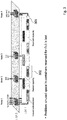
- Fig. 1 shows a sample scenario in which 2 ERP customers with reservation and other customers without reservation share a transport network ring.
- Three different paths are shown to represent ERP capacity used in normal state (indicated by path 101), ERP spare capacity for failure condition (indicated by path 102) and other non-isochronous customers (indicated by path 103).
- Isochronous traffic implies constant bit rate where reserved time slots are periodically provided and containers are transmitted in fixed time periods. Non-isochronous traffic does not have such reserved periodic time slots or containers.
- the terms "isochronous” and “reserved” are interchangeably used in the following.
- the Ring Protection Link In a normal state, the Ring Protection Link (RPL) is deactivated and traffic flows occupy the reserved ERP capacity used in the normal state as indicated by path 101. If a link failure occurs (e.g. between nodes 3 and 4 as indicated by 104), the RPL of the customer cu1 (as indicated by 102 1 ) is activated such that interrupted traffic flows (e.g. from node 5 to node 3) will use the ERP spare capacity in the other direction (i.e. via node 1 instead of via node 4) as indicated by path 102 1 .
- the ERP spare capacity for failure conditions needs to be reserved in advance to be ready when needed. As illustrated in Fig.
- a LAG is used to connect a customer site to e.g. a central office or another cloud destination via different provider edge (PE) routers.
- PE provider edge
- FIG. 3 schematically illustrates an example of a network with reserved connection.
- the network is shared by non-reservation customers cu2 - cu4 and by reserved-connection customer cu1.
- pipe 301 is reserved for customer cu1 for transmitting the client signal of cu1 from node 4 to node 1 using containers 302.
- the pipe 301 reserved for cu1 cannot be accessed by customers 3 and 4 at intermediate nodes 3 and 2 which are regarded as transit nodes for cu1.
- the client signal includes both data symbols and idle symbols, and the idle symbols occupying corresponding space may form wasted idle subcontainers in the containers 302.
- the client signal includes both data symbols and idle symbols, and the idle symbols occupying corresponding space may form wasted idle subcontainers in the containers 302.
- such unused capacity cannot be made available to other clients at transit nodes, and the unused space in containers 302 reserved for cu1 is lost (by wasting transport capacity with idle subcontainers).
- the spare capacity which is held ready for protection represents stranded bandwidth during normal operation.
- the present document proposes methods and devices for transmitting data packets in an optical transmission network with an improved flexibility and optimal usage of transmission resource, and in particular, to re-circulate stranded protection capacity in Ethernet transport networks.
- An aspect of the disclosure relates to a method for transmitting a client stream through an optical transmission network.
- the optical transmission network typically comprises multiple nodes, such as a transmitting node which may be coupled with a client who generated or is associated with the client stream, a receiving node which may be a destination node to which the client stream is directed to, a switching node which may be located along a path which transmission of the client stream follows, and so on.
- the client stream comprises at least one client packet and idle symbols.
- An example of such client stream is Ethernet traffic received at a client interface of the transmitting node.
- the client stream may comprise one or more MAC packets which may contain e.g. header information, a preamble section and data symbols.
- the client stream may be transmitted by synchronously placing the at least one client packet in one or more containers of the transmission network.
- further information related to the client packets such as header symbols or a preamble may be placed in the containers.
- a container may comprise a container header including address information, e.g. a destination address and a source address, and a sequence of subcontainers.
- the one or more containers are routed through the network based on the address information in container headers.
- the container(s) may be routed according to the destination address so that the container(s) can reach a destination node associated with the destination address.
- the subcontainers include subcontainer headers and payload portions.
- the method comprises obtaining the client stream at a client interface.
- the client interface may be included in a node of the optical transmission network, e.g. a transmitting node, and is generally coupled to a client who is associated with the client stream.
- the method comprises inserting the client stream in one or more payload portions of subcontainers.
- the at least one client packet and the idle symbols of the client stream may be inserted or encapsulated in the payload portion(s) of subcontainers.
- the subcontainer payload portion(s) comprise data symbols of the at least one client packet and/or idle symbols.
- a subcontainer payload portion may comprise data symbols of the at least one client packet or idle symbols, or a mixture of data symbols and idle symbols.
- the method also comprises determining whether a subcontainer payload portion only comprises idle symbols. If a subcontainer payload portion only comprises idle symbols, the method further comprises marking the subcontainer as idle subcontainer to make the idle subcontainer available for transport of another client stream or streams.
- the marking of an idle subcontainer may be in the header of the subcontainer or at some other place in the respective container that includes the idle subcontainer. For example, the marking may be in a container header or in headers of other subcontainers that precede or follow the idle subcontainer.
- a subcontainer payload portion only comprises data symbols or comprises a mixture of data symbols and idle symbols
- the subcontainer may remain unchanged or may be marked as busy/occupied subcontainer indicative of not being available for transport of another client stream.
- the determination may be performed for the sequence of subcontainers of the one or more containers, and, subsequently, the method comprises transmitting the one or more containers on an interface of the optical transmission network.
- the interface may also be included in the node of the optical transmission network, e.g. a transmitting node, and the one or more containers carrying the client stream may be sent/output from the node to the optical transmission network for transport through the interface.
- the method may comprise determining whether an idle subcontainer is identified/determined. If an idle subcontainer is determined, the method may further comprise, prior to transmitting, skipping the idle subcontainer and moving a subsequent subcontainer (which contains content that may have been generated after the idle symbols included in the idle subcontainer) to the position of the idle subcontainer in the container. However, the method may comprise maintaining the idle marking for this subcontainer, so that the destination node of the container can identify the skipped idle subcontainer and insert the skipped idle symbols in the recovered client stream. The marking of an idle subcontainer may be in the header of the subcontainer that, due to moving forward in the subcontainer sequence, is in place of the skipped subcontainer.
- a skipped idle subcontainer counter is provided in subcontainer headers to indicate the number of preceding idle subcontainers that have been skipped in the subcontainer sequence before the present subcontainer.
- a zero value in the skipped idle subcontainer counter indicates that no subcontainer has been skipped
- a one value indicates that one subcontainer in the sequence has been skipped before the present subcontainer, etc.
- an idle subcontainer can be signaled in the header of a subcontainer that precedes the skipped idle subcontainer.
- a skipped idle subcontainer can be identified at the destination node and the corresponding skipped idle symbols can be inserted properly. It is therefore appreciated that the number of inserted idle symbols can be precisely determined to enable perfect recovery of client streams.
- the idle subcontainer in slot number "i" in the sequence of subcontainers is omitted and the subsequent subcontainer number "i+1” is moved to slot number "i", and all following subcontainers k with k > i+1 are moved forward by one slot.
- This procedure may be repeated for all idle subcontainers so that all idle subcontainers are removed from the container(s) and the client stream is compressed.
- a container header may comprise container occupancy information indicative of the container space occupied by subcontainers.
- a container header may comprise container occupancy information indicative of free container space (i.e. the container space which is not occupied by subcontainers).
- an idle subcontainer may be skipped in the sequence of subcontainers, and a subsequent subcontainer may be moved to its position, which results in a free subcontainer at the end of the container (i.e. compression effect). Accordingly, the container occupancy information may be updatd to account for the free space provided by the free subcontainer.
- the subcontainer headers may comprise a free/occupied field to indicate whether the payload portion of a subcontainer is filled with client data. Accordingly, the number of the skipped idle subcontainer associated with the free/occupied field included in the subcontainer headers can be identified by the free/occupied field included in the subcontainer headers at the destination node.
- the one or more subcontainer payload portions may comprise forward error correction (FEC) information associated with the data in the payload portion(s) (which may contain a part of a client packet, or one or more client packets) to protect the at least one client packet against transmission errors.
- FEC forward error correction
- a container header may also comprise FEC information associated with information included in the container header to protect the information related to the container header against transmission errors.
- the space occupied by the idle subcontainer(s) can be set free and reused for transmission of further client packets and thus for transport of other client streams.
- the proposed solution which compresses a container by skipping the idle subcontainers, provides free subcontainers at the end of a container (i.e. the free container space is located at the end of the container) and provides a packet transport which is highly compatible with the existing media access mechanism. As such, free container capacity (at the end of the container) can be used more effectively and can be made available for any other clients along the path through the optical transmission network.
- the optical transmission network comprises multiple nodes, including e.g. a transmitting node which may be coupled with a client who generated or is associated with the client stream, a receiving node which may be a destination node to which the client stream is directed to, and a switching node which may be located along a path which transmission of the client stream follows.
- a container may comprise a container header including address information, such as a destination address and a source address, and a sequence of subcontainers.
- the one or more containers are routed through the network based on the address information in container headers. For example, the container(s) may be routed according to the destination address so that the container(s) can reach a destination node associated with the destination address.
- the subcontainers include subcontainer headers and payload portions.
- the method comprises receiving the one or more containers at an interface of the optical transmission network.
- the one or more containers may have been processed to encapsulate the client stream according to the aforementioned transmitting method (e.g. compressed containers having free space or containing further client packets at the end of the containers).
- the interface may be included in a node of the optical transmission network, e.g. a receiving node, and the one or more containers carrying the client stream may be received/input from the optical transmission network to the node through the interface.
- the method comprises extracting the at least one client packet from one or more subcontainer payload portions of the received containers, in particular, extracting the at least one client packet which has been inserted or encapsulated in the payload portion(s) of subcontainers.
- the at least one client packet can be recovered from the container(s) to obtain a recovered client stream.
- the subcontainer payload portion(s) of the received containers may comprise data symbols of the at least one client packet. More specifically, a subcontainer payload portion may comprise data symbols of the at least one client packet or a mixture of data symbols and idle symbols. As mentioned above, idle subcontainers only containing idle symbols may have been skipped in the containers.
- the method also comprises determining whether a subcontainer is marked as idle subcontainer. Similar to the above mentioned transmitting method, a subcontainer may have been marked if its subcontainer payload portion only included idle symbols. Besides, the idle symbols may have been skipped, but the idle marking for this subcontainer may be maintained for identification. According to this, if a subcontainer is marked as idle subcontainer, the method further comprises inserting one or more idle symbols in a recovered client stream. The number of the idle symbols to be inserted corresponds to the known number of the idle symbols contained in the skipped idle subcontainer. On the other hand, if a subcontainer is not marked as idle subcontainer (e.g.
- the method comprises outputting the recovered client stream at a client interface.
- the client interface may be also included in the node (e.g. a receiving node), and is generally coupled to a client destination to which the client stream is directed to.
- the subcontainer headers may comprise a skipped idle subcontainer counter.
- the skipped idle subcontainer counter may be associated with a marked idle subcontainer and can be used for identifying the idle subcontainer having contained only idle symbols.
- the skipped idle subcontainer counter may indicate a number of preceding idle subcontainers that only contained idle symbols and have been skipped in the subcontainer sequence before the present subcontainer (that is associated with the subcontainer header within which a skipped idle subcontainer counter is presently read).
- the method may further comprise identifying the number of preceding idle subcontainers indicated in a subcontainer header of a received container.
- the method may further comprise inserting one or more idle symbols between two consecutive extracted client packets in the recovered client stream.
- a number of idle symbols may be inserted between the two consecutive extracted client packets in case that one or more skipped idle subcontainers are identified between the two client packets.
- the number of the idle symbols to be inserted is determined based on the identified number of preceding idle subcontainers that is indicated by the subcontainer header associated with the succeeding one of the two consecutive extracted client packet. More specifically, the number of the idle symbols to be inserted may correspond to the number of the idle symbols contained in an idle subcontainer multiplied by the identified number of preceding idle subcontainers. Accordingly, client streams can be successfully retrieved from compressed containers where idle symbols have been removed to provide free space in the containers for transport of further client packets (streams).
- client streams including client packets and idle symbols can be well recovered, which enables efficient re-circulation of free container capacity for transmitting other client streams along the path through the optical transmission network.
- the same number of idle symbols as compressed in the sender can be directly inserted in the client stream without being subject to clock differences between the Ethernet interface of the sender and the Ethernet interface of the receiver. Since the information regarding the number of preceding skipped idle symbols is transmitted together with the packets, clock information to be transmitted can be preserved and clock synchronization can be thus remained throughout the network.
- the transmitting method may be applicable to further transmit a client stream which has been transmitted using the aforementioned transmitting method, and which is to be received using the aforementioned receiving method.
- the optical transmission network comprises multiple nodes, including, for example, a transmitting node which may be coupled with a client who generated or is associated with the client stream, a receiving node which may be a destination node to which the client stream is directed to, and a transit or switching node which may be located along a path which transmission of the client stream follows.
- the transmitting method may take place at, for example, a switching node of the optical transmission network.
- a container may comprise a container header including address information, such as a destination address and a source address, and a sequence of subcontainers.
- the one or more containers are routed through the network based on the address information in container headers. For example, the container(s) may be routed according to the destination address so that the container(s) can reach a destination node associated with the destination address.
- the sequence of subcontainers include subcontainer headers and payload portions.
- the one or more containers may be transported using a protected path which has capacity reserved for a client entity associated with the client stream. In other words, the one or more containers may be reserved for the client entity associated with the client stream.
- the method comprises receiving the one or more containers at an interface of the optical transmission network.
- the interface may be included in a node of the optical transmission network, e.g. a switching node, and the node is also coupled to a further client entity who may wish to transmit a further client stream via the optical transmission network (i.e. the further client stream may be associated with the further client entity coupled with the node).
- the further client stream may be encapsulated in its own container(s) to be routed to a destination based on the corresponding address information.
- the node may be located along a transmission of the client stream, and the at least one client packet of the client stream may thus pass the node during transmission. That is, the node may be regarded as a transit node for the one or more containers reserved for the client entity.
- the one or more containers may have been processed to encapsulate the client stream according to the aforementioned transmitting method (e.g. compressed containers having free space or containing further client packets at the end of the containers).
- a subcontainer header may include information whether a subcontainer at the same position in the subcontainer sequence at the transmitting node was an idle subcontainer that has been skipped by the transmitter of the container.
- the method comprises determining whether at least one free subcontainer is available in a received container for transport of a further client stream locally received at the switching node.
- the further client stream may particularly comprise at least one further client packet directed to the destination node of the received container.
- the node may determine whether the further client packet is directed to the destination node of the received container by comparing the address information of the respective container(s) for the client packet(s) and address information of the further client packet(s). If at least one further client packet is directed to the destination node of the received container(s), the method comprises inserting the at least one further client packet in the available at least one free subcontainer of the one or more received containers.
- the method also comprises transmitting the received and supplemented as explained above one or more containers on an interface of the optical transmission network to a further node.
- the interface may also be included in the node, e.g. the switching node, and the one or more containers carrying the client stream and the further client stream may be sent/output from the node to the optical transmission network for transport through the interface.
- the method may also comprise updating the container headers of the one or more received containers to include updated occupancy information based on the at least one further client packet.
- the updated occupancy information may indicate that the at least one further client packet has been inserted in the container by updating the length of the occupied/free subcontainers in the container.
- FEC forward error correction
- the method may further comprise updating the FEC information included in the subcontainer payload portion(s) associated with the at least one client packet based on the at least one client packet and the inserted at least one further client packet. In some embodiments, the method may also comprise determining whether the destination node of the one or more received containers is reached and forwarding the client packet to the further client entity coupled with the node in case that the destination node of the one or more received containers is reached.
- the proposed method enables an aggregation of multiple client packets (e.g. Ethernet data packets or IP data packets) of different source nodes in a container and also enables to include further client packets received at an intermediated node into the container without completely decoding the container for inserting the packets at the node, thereby providing high compatibility with the current access media mechanism.
- client packets e.g. Ethernet data packets or IP data packets
- An aspect of the disclosure relates to an optical transmitting node for transmitting a client stream comprising at least one client packet through an optical transmission network comprising multiple nodes.
- the optical transmitting node may configured to perform the above mentioned transmitting method.
- the optical transmitting node may be configured to transmit the client stream by synchronously placing the at least one client packet in one or more containers that are routed through the network based on address information in container headers.
- a container comprises a sequence of subcontainers having subcontainer headers and payload portions.
- the optical transmitting node comprises a client interface and a processing unit.
- the client interface is configured to obtain the client stream associated with a client entity coupled with the client interface.
- the client stream may comprise the at least one client packet and idle symbols.
- the processing unit is configured to insert the client stream in one or more payload portions of subcontainers. Also, the processing unit is configured to determine whether a subcontainer payload portion only comprises idle symbols. Similar to the transmitting method, the processing unit may be configured to mark the subcontainer as idle subcontainer, in case that a subcontainer payload portion only contains idle symbols, to make the idle subcontainer available for transport of another client stream.
- the optical transmitting node further comprises an optical output interface coupled with the optical transmission network. The optical output interface is configured to transmit the one or more containers through the optical transmission network.
- the processing unit may be further configured to skip the idle subcontainer and move a subsequent subcontainer to the position of the idle subcontainer in the container but maintain the idle marking for this subcontainer.
- a skipped idle subcontainer counter may be provided in subcontainer headers to indicate the number of preceding idle subcontainers that have been skipped in the subcontainer sequence before the present subcontainer.
- the one or more subcontainer payload portions may comprise forward error correction (FEC) information associated with the data in the subcontainer payload portion(s) which may contain a portion of a client packet or one or more client packets.
- FEC forward error correction
- a container header may comprise container occupancy information indicative of the container space occupied by subcontainers or of free container space.
- container occupancy information indicative of the container space occupied by subcontainers or of free container space.
- an idle subcontainer is skipped in the sequence of subcontainers and a subsequent subcontainer is moved to its position so that a free subcontainer at the end of the container results and the container occupancy information is updated to account for the free space provided by the free subcontainer.
- the proposed optical transmitting node adapts transport containers to make free space thereof available by removing idle symbols and marking skipped idle subcontainers accordingly (which can be regarded as compression of data in the containers). It is appreciated that the free space made available through the compression effect can be reused by other client packets, especially by further client packets received at transit nodes for the containers.
- Another aspect of the disclosure relates to an optical receiving node for receiving a client stream comprising at least one client packet via an optical transmission network comprising multiple nodes.
- the at least one client packet has been synchronously placed in one or more containers that are routed through the network based on address information in container headers.
- a container in general comprises a sequence of subcontainers having subcontainer headers and payload portions.
- the optical receiving node comprises an optical input interface coupled with the optical transmission network.
- the optical input interface may be configured to receive the one or more containers.
- the optical receiving node also comprises a processing unit and a client interface.
- the processing unit is configured to extract the at least one client packet from one or more subcontainer payload portions of the received containers.
- the processing unit is further configured to determine whether a subcontainer is marked as idle subcontainer and insert one or more idle symbols in a recovered client stream in case that a marked idle subcontainer is determined.
- the client interface is configured to output the recovered client stream.
- marking of a subcontainer as idle subcontainer may have been carried out by the transmitter in a header of the idle subcontainer or in a subcontainer header of a subsequent subcontainer to a skipped idle subcontainer.
- a skipped idle subcontainer counter in a subcontainer header indicates how many previous subcontainers in the subcontainer sequence have been skipped before the present subcontainer by the transmitter
- the subcontainer headers may comprise a skipped idle subcontainer counter which indicates a number of preceding idle subcontainers that only contained idle symbols and have been skipped in the subcontainer sequence before the present subcontainer before the containers have been transmitted.
- the processing unit may be further configured to identify the number of preceding idle subcontainers indicated in a subcontainer header of a received container.
- the optical receiving node may further comprise an idle subcontainer buffer configured to provide the one or more idle symbols to be inserted in the recovered client stream.
- the processing unit may be further configured to receive one or more idle symbols from the idle subcontainer buffer and insert them between two consecutive extracted client packets in the recovered client stream. It is appreciated that a number of the idle symbols to be inserted may be determined based on the identified number of preceding idle subcontainers that is indicated by the subcontainer header associated with the succeeding one of two consecutive extracted client packet.
- the proposed optical receiving node identifies the skipped idle subcontainer(s) and adds an appropriate number of idle symbols to the extracted client packet(s), which enables reliable recovery of the client stream (which contains client packets and idle symbols) and therefore allows to efficiently re-circulate free container capacity for transmitting other client streams along the path through the optical transmission network.
- an optical switching node for transmitting a client stream comprising at least one client packet through an optical transmission network comprising multiple nodes.
- the at least one client packet has been synchronously placed in one or more containers that are routed through the network based on address information in container headers.
- a container comprises a sequence of subcontainers having subcontainer headers and payload portions, and a subcontainer header including information whether a subcontainer at the same position in the original subcontainer sequence was an idle subcontainer that has been skipped in the received sequence of subcontainers.
- the optical switching node comprises an optical input interface coupled with the optical transmission network and configured to receive the one or more containers.
- the optical switching node comprises a client interface coupled with a further client entity associated with the further client stream.
- the client interface is configured to receive a further client stream comprising at least one further client packet directed to the destination node of the received container.
- the optical switching node further comprises a processing unit configured to determine whether at least one free subcontainer is available in a received container for transport of the further client stream and to insert the at least one further client packet in the available at least one free subcontainer of the one or more received containers.
- the optical switching node comprises an optical output interface coupled with the optical transmission network and configured to transmit the one or more containers to a further node.
- the processing unit may be further configured to update the container headers of the one or more received containers to include updated occupancy information based on the at least one further client packet.
- the one or more containers may be reserved for a client entity associated with the client stream. It is further appreciated that the further client stream may be associated with the further client entity coupled with the optical switching node.
- the proposed optical switching node adds a further client stream to the free space of the reserved container(s), which provides a flexible mechanism to be adapted to the existing multipoint-to-point systems.
- client packets of different source nodes can be transported using a reserved capacity without significant modification of the current media access mechanism.
- a basic aspect in this disclosure comprises methods and devices which allow to build containers for long-distance transport, whose unused capacity can be used by downstream nodes.
- the disclosed solution provides a transport/access mechanism which reuses the spare capacity in containers that is reserved for protection in case of failure conditions, so that stranded bandwidth is minimized during normal operation.
- Fig. 4 schematically illustrates a possible structure of a client stream 400 for transport through an optical transmission network according to embodiments of the disclosure.
- the optical transmission network can be, for example, SDH or OTN networks that reserve backup links using ERP or LAG scenarios as shown in Fig. 1 and Fig. 2 , respectively.
- the client stream 400 is sent by a sender 410 and is received by a receiver 411, and that is, the sender 410 and the receiver 411 can be regarded as an optical transmitting node and an optical receiving node in the optical transmission network, respectively.
- the client stream 400 includes one or more client packets 401.
- the one or more client packets can be an Ethernet packet (also referred as MAC packet) which has a frame structure as indicated by 401.
- an Ethernet frame within an Ethernet packet may include a preamble section, start frame delimiter (SFD) marking the end of the packet preamble, destination MAC address (DA), source MAC address (SA), EtherType for indicating the protocol encapsulated in the payload (Data) of the frame and a frame check sequence (FCS).
- SFD start frame delimiter
- DA destination MAC address
- SA source MAC address
- EtherType for indicating the protocol encapsulated in the payload (Data) of the frame
- FCS frame check sequence
- Ethernet interfaces continuously transmit idle symbols (/I/) 404 when they have no data to send, while data packets (e.g. Ethernet MAC packets) are bordered by start (/S/) symbols 402 and termination (/T/) symbols 403. As shown, the first byte of the preamble section of the MAC packet may be converted into a /S/ symbol 402.
- symbol information i.e. a symbol stream
- the sender 410 e.g. an optical Ethernet (OE) client at a transmitting node
- the receiver 411 e.g. a client port in an OE access node at a receiving node
- block encoding e.g. 64B/66B
- a symbol stream can be observed e.g. across the 10 gigabit media-independent interface (XGMII) as defined in the IEEE 802.3 standard.
- OE maps this symbol sequence (stream) seamlessly into a synchronous stream of (sub-) containers reserved for this connection which provides the same bitrate as the client port (which may be referred as "encapsulation" processes).
- a container comprises a container header 405 having a destination address and a plurality of subcontainers which may include data symbols and/or idle symbols of the client stream 400.
- a subcontainer which includes a data symbol may be referred as data subcontainer 406, while a subcontainer which only contains idle symbols may be referred as idle subcontainer 407.
- this MAC-packet encoding and container aggregation may be performed at the physical-layer service interface.
- Fig. 5 schematically illustrates a possible structure of a container 500 for transport through an optical transmission network according to embodiments of the disclosure. More specifically, the container 500 represents an OE container structure used for carrying the client packet(s) 401 of a client stream 400 as described in Fig. 4 .
- Fig. 5 depicts a general view of encapsulation of a client stream (e.g. the client stream 400 ) into a container 500 to be transmitted in the optical transmission network.
- the container 500 comprises a container header 501 and a container payload portion 502.
- the containers 500 transmitted between the nodes comprise a container header 501 which includes information regarding a destination node of the container 500.
- the container header 501 may comprise address information such as destination address information 503 and source address information 504.
- the source address information 504 indicates a source node from which data included in the container 500 that are associated with the source address information are sent.
- the destination address information 503 indicates that all data included in the container 500 are directed to a destination node (e.g. a receiving node or a switching node) associated with the destination address information 503.
- a destination node e.g. a receiving node or a switching node
- the destination address information 503 is analyzed in order to be able to decide whether client packets received at the switching node are directed to the destination node of the container and the client packets are included in the container 500 if the destination to which the client packets are directed to matches the destination node of the container.
- the container header 501 may comprise container occupancy information 505 being indicative for the used/unused capacity of the container payload portion 502.
- the container occupancy information 505 may indicate the number of occupied and/or free subcontainers 506.
- the container 500 may comprise a fixed payload portion capacity comprising a fixed number of subcontainers 506. Thus, it may be sufficient to indicate either the number of occupied subcontainers 506 or the number of free subcontainers 506 in order to determine the used/unused capacity of the payload portion 502.
- the container header 501 may comprise FEC information which may refer to the above indicated information included in the container header 501, i.e. in case of transmission errors, the container header information (e.g. the destination address information 503, source address information 504 and container occupancy information 505 ) can be recovered by the FEC information.
- the FEC information may be applied to protect the container header information. Further FEC information may also be applied to protect the container payload.
- the container 500 is protected against transmission errors using a modular FEC configuration which applies header FEC information referring only to the container header 501 and payload FEC information referring only to the container payload portion 502.
- the above mentioned container header 501 is adapted to be decoded (e.g. in real-time) by an intermediated node (e.g. a switching node) arranged between the source node (e.g. a transmitting node) and the destination node (e.g. a receiving node) in order to determine the destination node and the free capacity of the container 500.
- the intermediate node is able to determine whether client packets received at the intermediate node from a client entity (e.g. a router) for transmission via the optical transmission network to the destination node should be included in the container 500, and whether free capacity of the container payload 502 is sufficient for transmitting at least a portion of the client packets.
- the plurality of subcontainers in a container also include a FEC portion 507, a subcontainer header 508 and payload portion.
- each of the subcontainers includes a subcontainer header 508 having a size of 2 byte to indicate, for example, whether the payload portion of subcontainer is filled with client data.
- the subcontainer payload portion may include the FEC portion associated with the data in the subcontainer payload portion (e.g. a part of a client data packet or one or more client data packets).
- a compression process may be performed to a container (i.e. the subcontainers containing data) before transmission.
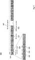
- Fig. 7 schematically illustrates a possible implementation of container compression according to embodiments of the disclosure.
- the compress process can be performed to the container 500 comprising the plurality of subcontainers 506.
- 700a represents an uncompressed container (before compression) which has similar structure as illustrated in Fig. 4 , comprising a container header 701 and a payload portion divided into a plurality of subcontainers 702.
- each subcontainer 702 includes a subcontainer header 703 and a subcontainer payload portion which may have data symbols associated with the client packet(s) and/or idle symbols.
- a subcontainer which includes a data symbol may be referred as data subcontainer 704, while a subcontainer which only contains idle symbols may be referred as idle subcontainer 705.
- the container 700a may be reserved in a protection path for a certain client entity.
- the subcontainers may have a header field 706 used to encode the number of preceding idle subcontainers. While the container is filled with the client stream subcontainer by subcontainer, a subcontainer only containing /I/ symbols is marked as idle (i.e. an idle subcontainer) in the header field 706 of the subcontainer header.
- a number representation i.e. a number of idle subcontainers
- free space of a container can then be identified (by e.g.
- the container destination may be provided in the destination address field of the container header 701 indicated by 405, 501.
- the occupancy information field of the container header 701 (denoted as a length field, LEN) may indicate the length (number) of occupied subcontainers or free subcontainers by pointing to the last occupied subcontainer in the container (as represented by arrow 710 ) close to the end of the container.
- the length field (LEN) in the container header 701 indicates the number of contiguous, occupied subcontainers inside the container starting from the beginning of the payload section.
- LEN is normally smaller than 80, which means that there are 80-LEN free subcontainers at the end of the container.
- a reserved container comprises idle subcontainers which are typically not contiguous, but are rather distributed across the container with data subcontainers in between.
- the OE container header can also carry a map of subcontainer reservation state, but the map may require 1 bit for each subcontainer, which leads to more than twice the current header size.
- the increasing size in a container header results in a challenge for the real-time processing of containers in transit nodes.
- a solution proposed according to the disclosure is illustrated by the compressed container 700b (after compression).
- the subcontainer is marked as idle subcontainer as indicated by 705 of 700a.
- a subsequent data subcontainer 709 is moved to the position of the idle subcontianer 705 but the idle marking is maintained.
- the data subcontainer 709 indicates (as shown by the subcontainer header 707 ) two preceding idle subcontainers and has been moved up to the position right after the data subcontainer 704 to achieve contiguous subcontainer occupation. Accordingly, the subcontainers containing data (the data subcontainers) of the container 700b are compressed so that free subcontainers 708 are available at the end of the container 700b.
- the length field in the container header of the container 700b thus indicates the length of occupied subcontainers or free subcontainers pointing to the last occupied subcontainer in the container.
- FEC encoding and in-flight boarding may also be applied to the compressed container, i.e. by applying FEC information associated with the client packets to the subcontainer payload portions.
- the receiver can directly insert indicated number of idle subcontainers into outgoing client streams, which provides full compatibility with the existing media access mechanism.
- the compression of data subcontainers does not interfere with proprietary use of preamble space or inter-packet gap.
- Fig. 6 schematically illustrates an example architecture of an optical transmission network 600 according to embodiments of the disclosure.
- the architecture comprises multiple nodes 610a , 610b, 610c, 610d which are interconnected by optical transmission links 620.
- the optical transmission links 620 may be optical fibers.
- the optical transmission network can be, for example, SDH or OTN networks that reserve backup links using ERP or LAG scenarios as shown in Fig. 1 and Fig. 2 , respectively.
- each node 110a , 110b, 110c, 110d or a subset of nodes 110a , 110b, 110c, 110d may comprise a switching element included in the optical transmission layer (L0/L1 according to OSI-model), i.e.
- the respective switching element of the node 110a , 110b, 110c, 110d may be coupled with a switching or routing element included in an upper network layer (e.g. layers L2/L3 of the OSI-model).
- the switching or routing element may be coupled with a client entity and can be regarded as a client interface.
- the switching element coupled with the optical transmission links 620 can be regarded as an optical input/output interface.
- Data packets may be received at the switching or routing element (i.e. the client interface) from its corresponding switching element (i.e. the optical input/output interface).
- client data packets may be routed by the optical input/output interface to the client interface in order to forward the client data packets to a client entity cu1, cu2, cu3, cu4 coupled with the client interface.
- the optical input/output interface may receive client data packets from a client entity cu1, cu2, cu3, cu4 in order to transmit the client data packets via the optical transmission network 600 to a destination node. The client interface then forwards the received data packets to the optical input/output interface in order to be transmitted via the one or more optical transmission links 620.
- a client entity cu1 (e.g. a server computer or a personal computer) coupled with the client interface of the node 610a may generate Ethernet packets (i.e. client data) for transmission over the optical transmission network 600. These Ethernet packets may be inserted by the node 610a into a container as described above. Further, the client entity cu1 may receive Ethernet packets from the node 610a . After transmission, the Ethernet packets are received in a container at a node being the destination of the container. For example, the node 610d may determine whether the destination address indicated by the container header of the container match its address and may receive the container if the node 610d is the destination node of the container.
- the node 610a obtains, at its client interface, a client stream from the client cu1 and inserts the client stream in one or more payload portions of subcontainers in the containers 603 to be transmitted through the network 600.
- a portion of capacity 601 provided by the optical transmission links 620 may be reserved for the container 603 associated with the client cu1 at the node 610a .
- the rest of the capacity 602 provided by the optical transmission links 620 is available for transport of other client streams associated with other client cu2, cu3, cu4.
- the optical transmission network 600 may be adapted to support WDM, so that different clients cu1, cu2, cu3, cu4 may use multiple different wavelengths to transmit their client streams.
- the other client streams may also be inserted into respective containers as indicated by 604 2 , 604 3 , 604 4 to be transmitted using the rest of the link capacity 602. Since the container 603 associated with the client cu1 is sent by the node 610a and is received by the node 610d, the node 610a and the node 610d can be regarded as an optical transmitting node and an optical receiving node in the optical transmission network, respectively. On the other hand, nodes 610b and 610c, accessible by the clients cu3 and cu4, respectively, may be regarded as transit/switching nodes for the container 603.
- the node 610a may insert the client stream in the containers 603 according to the mechanism as described in Fig. 7 .
- the node 610a may, through a processing unit thereof (e.g. a DSP), determine whether a subcontainer payload portion only has idle symbols and mark the subcontainer as idle subcontainer. Further, if an idle subcontainer is determined, the node 610a may also skip the idle subcontainer and move a subsequent subcontainer to the position of the idle subcontainer in the container 603 but maintain the idle marking for this subcontainer. Accordingly, the idle subcontainer can be made available or the free space may be available at the end of the container 603 for transport of other client streams (as illustrated by the container 603 1 ).
- nodes 610b and 610c receive, at their client interface, a further client stream associated with clients cu3 and cu4, respectively, and compare the address information of the container 603 for the client packets and the address information of further client packets included in the further client stream.
- the further client packets may be directed to the destination node of the container 603.
- the nodes 610b and 610c also determine whether a free subcontainer is available in the container 603 or the free space is available at the end of the container 603 for transport of the further client stream.
- container 603 1 still has a free subcontainer at the end of the container 603
- container 603 2 carries a portion or one or more of the client packets of the client cu2 at the end of the container together with a portion or one or more of the client packets of the client cu1 (as indicated in the last two subcontainers)
- container 603 3 carries the a portion or one or more of client packets of the client cu3 at the end of the container together with a portion or one or more of the client packets of the client cu1 (as indicated in the last one subcontainers)
- container 603 4 carries a portion or one or more of the client packets of the clients cu3 and cu4 at the end of the container together with a portion or one or more of the client packets of the client cu
- client packets or portions of the client packets carried in the container 603 have the same destination (e.g. the node 610d as illustrated as a receiving node). Accordingly, subcontainers which are not used by the client cu1 can now be accessed by other clients cu2, cu3, cu4 giving them additional bandwidth.
- the destination node 610d has an idle subcontainer stored in a buffer 606 (e.g. an idle subcontainer buffer) to be inserted into the outgoing client stream whenever a subcontainer is received with the idle mark encoded.
- the destination node 610d receives the containers 603 and extracts the client packets from the subcontainer payload portions of the containers 603.
- the destination node 610d further determines whether a subcontainer is marked as idle subcontainer and inserts one or more idle symbols provided by the buffer 606 in a recovered client stream.
- the subcontainer having a subcontainer header as shown in Fig. 7 comprises a skipped idle subcontainer counter.
- the skipped idle subcotainer counter may indicate a number of preceding idle subcontainers that only contained idle symbols and have been skipped in the subcontainer sequence before the present subcontainer.
- the node 610d can identify the number of preceding idle subcontainers indicated in the subcontainer header of the containers 603. As a result, idle times in Ethernet life traffic are identified and their corresponding transport capacity is set free for other users through re-circulating idle subcontainers of the reserved connection, while the guaranteed-bandwidth service for the contract user is not impaired.
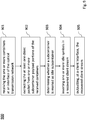
- Fig. 8 illustrates processing steps for the proposed method for transmitting a client stream through an optical transmission network according to embodiments of the disclosure.
- the method 800 can be implemented by, for example, the transmitting node 610a as illustrated in Fig. 6 .
- the method 800 comprises obtaining (step 801 ) the client stream at a client interface, the client stream comprising the at least one client packet and idle symbols and inserting (step 802 ) the client stream in one or more payload portions of subcontainers.
- the method 800 also comprises determining (step 803 ) whether a subcontainer payload portion only comprises idle symbols and in response, marking (step 804 ) the subcontainer as idle subcontainer to make the idle subcontainer available for transport of another client stream.
- the method comprises transmitting (step 805 ) the one or more containers on an interface of the optical transmission network.
- Fig. 9 illustrates processing steps for the proposed method for receiving a client stream through an optical transmission network according to embodiments of the disclosure.
- the method 900 can be implemented to receive a client stream which has been transmitted using the method 900.
- the method 900 can be implemented by, for example, the receiving node 610d as illustrated in Fig. 6 .
- the method 900 comprises receiving (step 901 ) the one or more containers at an interface of the optical transmission network and extracting (step 902 ) the at least one client packet from one or more subcontainer payload portions of the received containers.
- the method 900 also comprises determining (step 903 ) whether a subcontainer is marked as idle subcontainer and in response, inserting (step 904 ) one or more idle symbols in a recovered client stream.
- the method comprises outputting (step 905 ), at a client interface, the recovered client stream.
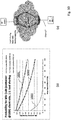
- Fig. 10 graphically illustrates theoretical analysis of the saved/re-circulated capacity using the proposed methods and devices according to embodiments of the disclosure.
- the analysis is done in a load-sharing LAG as illustrated in Fig. 10(a) , where a mean load of Poisson packet arrivals at an OE client interface of 100Gbps is assumed.
- This load is distributed by the OE access node 50% each across two disjoint paths of the load-sharing LAG. From the probability distribution function one can easily derive the probability for a packet inter-arrival time which is larger than or equal to the duration of a subcontainer.
- Fig. 10 graphically illustrates theoretical analysis of the saved/re-circulated capacity using the proposed methods and devices according to embodiments of the disclosure.
- the analysis is done in a load-sharing LAG as illustrated in Fig. 10(a) , where a mean load of Poisson packet arrivals at an OE client interface of 100Gbps is assumed.
- This load is distributed by the OE access node 50% each across
- FIG. 10(b) shows probability for idle subcontainer over the mean load of the client interface at 100Gbps of client rate for a transmission in a 50% load-sharing LAG of Fig. 10(a) .
- Curve 1001 represents the result for an empty subcontainer of 1280 bits (which corresponds to the current OE design)
- curve 1002 represents the result for an empty subcontainer of 10,000 bits
- curve 1003 represents the result for a container of 100,000 bits.
- saved capacity which is represented by the idle-container probability
- the probability for an empty subcontainer of 1280 bits is around 50%, which means that the entire protection capacity can be re-circulated. Since the mean client load may typically be lower (e.g. 50% to 80%), one can expect even higher savings on the load-sharing links. In particular, the savings decrease with increasing subcontainer size (indicated by curves 1001 and 1002 ) and become negligible for an entire container (indicated by 1003 ).
- transport network providers can free the unused network capacity reserved for electronical protection and make it available for any other user along the path through the network. This can substantially reduce overall network capacity dimensioning.
- the mechanism is transparent for Ethernet symbol transfer, i.e. proprietary usage of preamble space or inter-frame gap is not affected, because only subcontainers completely filled with idle symbols are re-circulated, any other content is considered as user data.
- the mechanism is fully compatible with the existing OE design. It uses the same media access mechanism and does not require additional processing in transit nodes, which may be useful for any transport node supporting Ethernet clients in the Metro area.
Abstract
Description
- This application relates to optical data transmission systems, and more particularly, to methods and devices for including data packets into a container passing a node thereby aggregating data to be directed to a destination node.
- In current optical networks such as Synchronous Digital Hierarchy (SDH) or Optical Transport Network (OTN), Ethernet clients are interconnected through digital transmission lines with constant, exclusively reserved capacity. Such a connection is widely referred to as a Carrier-Ethernet (CE) connection. Protection against failure is typically performed by reserving one or more backup links which can be realized on the optical layer (e.g. 1+1 protection) where a copy of a client signal is permanently transmitted on the backup path. Alternatively, backup links can also be realized on the electronical layer, where backup links are only activated and carry client traffic when needed (e.g. Link Aggregation Group (LAG) with active/standby link), or permanently, when used in load-sharing mode, e.g. Ethernet Ring Protection (ERP) or load-sharing LAG.
-
Fig. 1 shows a sample scenario in which 2 ERP customers with reservation and other customers without reservation share a transport network ring. Three different paths are shown to represent ERP capacity used in normal state (indicated by path 101), ERP spare capacity for failure condition (indicated by path 102) and other non-isochronous customers (indicated by path 103). Isochronous traffic implies constant bit rate where reserved time slots are periodically provided and containers are transmitted in fixed time periods. Non-isochronous traffic does not have such reserved periodic time slots or containers. The terms "isochronous" and "reserved" are interchangeably used in the following. - In a normal state, the Ring Protection Link (RPL) is deactivated and traffic flows occupy the reserved ERP capacity used in the normal state as indicated by
path 101. If a link failure occurs (e.g. betweennodes node 5 to node 3) will use the ERP spare capacity in the other direction (i.e. vianode 1 instead of via node 4) as indicated bypath 1021. The ERP spare capacity for failure conditions needs to be reserved in advance to be ready when needed. As illustrated inFig. 1 , cu1 is present atnodes nodes nodes nodes Fig. 2 in which a LAG is used to connect a customer site to e.g. a central office or another cloud destination via different provider edge (PE) routers. - In today's transport networks, capacity reserved for a client connection is a closed physical layer pipe between a source transport node and a destination transport node. However, this pipe belongs to exactly this client and cannot be accessed by other customers along its path.
Fig. 3 schematically illustrates an example of a network with reserved connection. The network is shared by non-reservation customers cu2 - cu4 and by reserved-connection customer cu1. As shown inFig. 3 ,pipe 301 is reserved for customer cu1 for transmitting the client signal of cu1 fromnode 4 tonode 1 usingcontainers 302. In general, thepipe 301 reserved for cu1 cannot be accessed bycustomers intermediate nodes containers 302. Hence, such unused capacity cannot be made available to other clients at transit nodes, and the unused space incontainers 302 reserved for cu1 is lost (by wasting transport capacity with idle subcontainers). Accordingly, the spare capacity which is held ready for protection represents stranded bandwidth during normal operation. - Thus, there is a need to re-circulate the capacity reserved for protection, in particular, for protection on the electronical layer which is applicable to the respective above mentioned scenarios (e.g. LAG, ERP, load-sharing LAG etc.). Similar ineffective usage of network capacity can happen in other scenarios and network configurations, e.g. in case of a reserved connection without failure protection.
- In view of these needs, the present document proposes methods and devices for transmitting data packets in an optical transmission network with an improved flexibility and optimal usage of transmission resource, and in particular, to re-circulate stranded protection capacity in Ethernet transport networks.
- An aspect of the disclosure relates to a method for transmitting a client stream through an optical transmission network. The optical transmission network typically comprises multiple nodes, such as a transmitting node which may be coupled with a client who generated or is associated with the client stream, a receiving node which may be a destination node to which the client stream is directed to, a switching node which may be located along a path which transmission of the client stream follows, and so on.
- Furthermore, the client stream comprises at least one client packet and idle symbols. An example of such client stream is Ethernet traffic received at a client interface of the transmitting node. For example, the client stream may comprise one or more MAC packets which may contain e.g. header information, a preamble section and data symbols. In general, the client stream may be transmitted by synchronously placing the at least one client packet in one or more containers of the transmission network. In addition to the client packets further information related to the client packets such as header symbols or a preamble may be placed in the containers. A container may comprise a container header including address information, e.g. a destination address and a source address, and a sequence of subcontainers. In particular, the one or more containers are routed through the network based on the address information in container headers. For example, the container(s) may be routed according to the destination address so that the container(s) can reach a destination node associated with the destination address. In addition, the subcontainers include subcontainer headers and payload portions.
- According to the disclosure, the method comprises obtaining the client stream at a client interface. The client interface may be included in a node of the optical transmission network, e.g. a transmitting node, and is generally coupled to a client who is associated with the client stream. Further, the method comprises inserting the client stream in one or more payload portions of subcontainers. For example, the at least one client packet and the idle symbols of the client stream may be inserted or encapsulated in the payload portion(s) of subcontainers. By this way, the subcontainer payload portion(s) comprise data symbols of the at least one client packet and/or idle symbols. More specifically, a subcontainer payload portion may comprise data symbols of the at least one client packet or idle symbols, or a mixture of data symbols and idle symbols.
- According to the disclosure, the method also comprises determining whether a subcontainer payload portion only comprises idle symbols. If a subcontainer payload portion only comprises idle symbols, the method further comprises marking the subcontainer as idle subcontainer to make the idle subcontainer available for transport of another client stream or streams. The marking of an idle subcontainer may be in the header of the subcontainer or at some other place in the respective container that includes the idle subcontainer. For example, the marking may be in a container header or in headers of other subcontainers that precede or follow the idle subcontainer. On the other hand, if a subcontainer payload portion only comprises data symbols or comprises a mixture of data symbols and idle symbols, the subcontainer may remain unchanged or may be marked as busy/occupied subcontainer indicative of not being available for transport of another client stream. The determination may be performed for the sequence of subcontainers of the one or more containers, and, subsequently, the method comprises transmitting the one or more containers on an interface of the optical transmission network. The interface may also be included in the node of the optical transmission network, e.g. a transmitting node, and the one or more containers carrying the client stream may be sent/output from the node to the optical transmission network for transport through the interface.
- In detail, the method may comprise determining whether an idle subcontainer is identified/determined. If an idle subcontainer is determined, the method may further comprise, prior to transmitting, skipping the idle subcontainer and moving a subsequent subcontainer (which contains content that may have been generated after the idle symbols included in the idle subcontainer) to the position of the idle subcontainer in the container. However, the method may comprise maintaining the idle marking for this subcontainer, so that the destination node of the container can identify the skipped idle subcontainer and insert the skipped idle symbols in the recovered client stream. The marking of an idle subcontainer may be in the header of the subcontainer that, due to moving forward in the subcontainer sequence, is in place of the skipped subcontainer. For example, a skipped idle subcontainer counter is provided in subcontainer headers to indicate the number of preceding idle subcontainers that have been skipped in the subcontainer sequence before the present subcontainer. In this case, a zero value in the skipped idle subcontainer counter indicates that no subcontainer has been skipped, and a one value indicates that one subcontainer in the sequence has been skipped before the present subcontainer, etc. In the same way, an idle subcontainer can be signaled in the header of a subcontainer that precedes the skipped idle subcontainer. By this way, a skipped idle subcontainer can be identified at the destination node and the corresponding skipped idle symbols can be inserted properly. It is therefore appreciated that the number of inserted idle symbols can be precisely determined to enable perfect recovery of client streams.
- In other words, the idle subcontainer in slot number "i" in the sequence of subcontainers is omitted and the subsequent subcontainer number "i+1" is moved to slot number "i", and all following subcontainers k with k > i+1 are moved forward by one slot. This procedure may be repeated for all idle subcontainers so that all idle subcontainers are removed from the container(s) and the client stream is compressed.
- In some embodiments, a container header may comprise container occupancy information indicative of the container space occupied by subcontainers. Alternatively, a container header may comprise container occupancy information indicative of free container space (i.e. the container space which is not occupied by subcontainers). As mentioned above, an idle subcontainer may be skipped in the sequence of subcontainers, and a subsequent subcontainer may be moved to its position, which results in a free subcontainer at the end of the container (i.e. compression effect). Accordingly, the container occupancy information may be updatd to account for the free space provided by the free subcontainer. In some embodiments, the subcontainer headers may comprise a free/occupied field to indicate whether the payload portion of a subcontainer is filled with client data. Accordingly, the number of the skipped idle subcontainer associated with the free/occupied field included in the subcontainer headers can be identified by the free/occupied field included in the subcontainer headers at the destination node.
- In some embodiments, the one or more subcontainer payload portions may comprise forward error correction (FEC) information associated with the data in the payload portion(s) (which may contain a part of a client packet, or one or more client packets) to protect the at least one client packet against transmission errors. Furthermore, a container header may also comprise FEC information associated with information included in the container header to protect the information related to the container header against transmission errors.
- Configured as above, by marking the idle subcontainer(s) which only contain idle symbols, the space occupied by the idle subcontainer(s) (including only idle symbols) can be set free and reused for transmission of further client packets and thus for transport of other client streams. In particular, the proposed solution, which compresses a container by skipping the idle subcontainers, provides free subcontainers at the end of a container (i.e. the free container space is located at the end of the container) and provides a packet transport which is highly compatible with the existing media access mechanism. As such, free container capacity (at the end of the container) can be used more effectively and can be made available for any other clients along the path through the optical transmission network.
- Another aspect of the disclosure relates to a method for receiving a client stream comprising at least one client packet via an optical transmission network. The receiving method may be applicable to receive a client stream which has been transmitted using the transmitting method as indicated above. In general, the optical transmission network comprises multiple nodes, including e.g. a transmitting node which may be coupled with a client who generated or is associated with the client stream, a receiving node which may be a destination node to which the client stream is directed to, and a switching node which may be located along a path which transmission of the client stream follows.
- In particular, the at least one client packet has been synchronously placed in one or more containers. Similar to the above mentioned embodiments, a container may comprise a container header including address information, such as a destination address and a source address, and a sequence of subcontainers. The one or more containers are routed through the network based on the address information in container headers. For example, the container(s) may be routed according to the destination address so that the container(s) can reach a destination node associated with the destination address. In addition, the subcontainers include subcontainer headers and payload portions.
- According to the disclosure, the method comprises receiving the one or more containers at an interface of the optical transmission network. The one or more containers may have been processed to encapsulate the client stream according to the aforementioned transmitting method (e.g. compressed containers having free space or containing further client packets at the end of the containers). The interface may be included in a node of the optical transmission network, e.g. a receiving node, and the one or more containers carrying the client stream may be received/input from the optical transmission network to the node through the interface. Further, the method comprises extracting the at least one client packet from one or more subcontainer payload portions of the received containers, in particular, extracting the at least one client packet which has been inserted or encapsulated in the payload portion(s) of subcontainers. By this way, the at least one client packet can be recovered from the container(s) to obtain a recovered client stream. It is noted that the subcontainer payload portion(s) of the received containers may comprise data symbols of the at least one client packet. More specifically, a subcontainer payload portion may comprise data symbols of the at least one client packet or a mixture of data symbols and idle symbols. As mentioned above, idle subcontainers only containing idle symbols may have been skipped in the containers.
- According to the disclosure, the method also comprises determining whether a subcontainer is marked as idle subcontainer. Similar to the above mentioned transmitting method, a subcontainer may have been marked if its subcontainer payload portion only included idle symbols. Besides, the idle symbols may have been skipped, but the idle marking for this subcontainer may be maintained for identification. According to this, if a subcontainer is marked as idle subcontainer, the method further comprises inserting one or more idle symbols in a recovered client stream. The number of the idle symbols to be inserted corresponds to the known number of the idle symbols contained in the skipped idle subcontainer. On the other hand, if a subcontainer is not marked as idle subcontainer (e.g. if a subcontainer is marked as busy/occupied subcontainer as mentioned above), no idle symbols may be inserted in a recovered client stream. The determination may be performed over the sequence of subcontainers for the one or more containers. Subsequently, the method comprises outputting the recovered client stream at a client interface. The client interface may be also included in the node (e.g. a receiving node), and is generally coupled to a client destination to which the client stream is directed to.
- According to some embodiments, the subcontainer headers may comprise a skipped idle subcontainer counter. The skipped idle subcontainer counter may be associated with a marked idle subcontainer and can be used for identifying the idle subcontainer having contained only idle symbols. In detail, the skipped idle subcontainer counter may indicate a number of preceding idle subcontainers that only contained idle symbols and have been skipped in the subcontainer sequence before the present subcontainer (that is associated with the subcontainer header within which a skipped idle subcontainer counter is presently read). With information provided by the skipped idle subcontainer counter, the method may further comprise identifying the number of preceding idle subcontainers indicated in a subcontainer header of a received container. By this way, the skipped idle subcontainers can be easily identified, and a required number of idle symbols can be added to the client packet(s) properly to efficiently recover the client stream.
- More specifically, the method may further comprise inserting one or more idle symbols between two consecutive extracted client packets in the recovered client stream. For example, a number of idle symbols may be inserted between the two consecutive extracted client packets in case that one or more skipped idle subcontainers are identified between the two client packets. In particular, the number of the idle symbols to be inserted is determined based on the identified number of preceding idle subcontainers that is indicated by the subcontainer header associated with the succeeding one of the two consecutive extracted client packet. More specifically, the number of the idle symbols to be inserted may correspond to the number of the idle symbols contained in an idle subcontainer multiplied by the identified number of preceding idle subcontainers. Accordingly, client streams can be successfully retrieved from compressed containers where idle symbols have been removed to provide free space in the containers for transport of further client packets (streams).
- Configured as above, by identifying the skipped idle subcontainer(s) and correspondingly adding idle symbols to the extracted client packet(s), client streams including client packets and idle symbols can be well recovered, which enables efficient re-circulation of free container capacity for transmitting other client streams along the path through the optical transmission network. In particular, according to the proposed method, the same number of idle symbols as compressed in the sender can be directly inserted in the client stream without being subject to clock differences between the Ethernet interface of the sender and the Ethernet interface of the receiver. Since the information regarding the number of preceding skipped idle symbols is transmitted together with the packets, clock information to be transmitted can be preserved and clock synchronization can be thus remained throughout the network.
- Another aspect of the disclosure relates to a method for transmitting a client stream comprising at least one client packet through an optical transmission network. The transmitting method may be applicable to further transmit a client stream which has been transmitted using the aforementioned transmitting method, and which is to be received using the aforementioned receiving method. As mentioned above, the optical transmission network comprises multiple nodes, including, for example, a transmitting node which may be coupled with a client who generated or is associated with the client stream, a receiving node which may be a destination node to which the client stream is directed to, and a transit or switching node which may be located along a path which transmission of the client stream follows. According to the disclosure, the transmitting method may take place at, for example, a switching node of the optical transmission network.
- In particular, at least one client packet has been synchronously placed in one or more received containers. Similar to the above mentioned embodiments, a container may comprise a container header including address information, such as a destination address and a source address, and a sequence of subcontainers. The one or more containers are routed through the network based on the address information in container headers. For example, the container(s) may be routed according to the destination address so that the container(s) can reach a destination node associated with the destination address. In addition, the sequence of subcontainers include subcontainer headers and payload portions. Moreover, the one or more containers may be transported using a protected path which has capacity reserved for a client entity associated with the client stream. In other words, the one or more containers may be reserved for the client entity associated with the client stream.
- According to the disclosure, the method comprises receiving the one or more containers at an interface of the optical transmission network. The interface may be included in a node of the optical transmission network, e.g. a switching node, and the node is also coupled to a further client entity who may wish to transmit a further client stream via the optical transmission network (i.e. the further client stream may be associated with the further client entity coupled with the node). Similar to the client stream, the further client stream may be encapsulated in its own container(s) to be routed to a destination based on the corresponding address information. The node may be located along a transmission of the client stream, and the at least one client packet of the client stream may thus pass the node during transmission. That is, the node may be regarded as a transit node for the one or more containers reserved for the client entity.
- As indicated above, the one or more containers may have been processed to encapsulate the client stream according to the aforementioned transmitting method (e.g. compressed containers having free space or containing further client packets at the end of the containers). In this case, a subcontainer header may include information whether a subcontainer at the same position in the subcontainer sequence at the transmitting node was an idle subcontainer that has been skipped by the transmitter of the container.
- According to the disclosure, the method comprises determining whether at least one free subcontainer is available in a received container for transport of a further client stream locally received at the switching node. The further client stream may particularly comprise at least one further client packet directed to the destination node of the received container. In more detail, the node may determine whether the further client packet is directed to the destination node of the received container by comparing the address information of the respective container(s) for the client packet(s) and address information of the further client packet(s). If at least one further client packet is directed to the destination node of the received container(s), the method comprises inserting the at least one further client packet in the available at least one free subcontainer of the one or more received containers.
- Subsequently, the method also comprises transmitting the received and supplemented as explained above one or more containers on an interface of the optical transmission network to a further node. The interface may also be included in the node, e.g. the switching node, and the one or more containers carrying the client stream and the further client stream may be sent/output from the node to the optical transmission network for transport through the interface.
- In some embodiments, the method may also comprise updating the container headers of the one or more received containers to include updated occupancy information based on the at least one further client packet. For example, the updated occupancy information may indicate that the at least one further client packet has been inserted in the container by updating the length of the occupied/free subcontainers in the container. Moreover, in order to protect the information related to the container header and/or the client packet(s) against transmission errors, forward error correction (FEC) information may be added to the container header and/or the subcontainer payload portion(s). In some embodiments, the method may further comprise updating the FEC information included in the subcontainer payload portion(s) associated with the at least one client packet based on the at least one client packet and the inserted at least one further client packet. In some embodiments, the method may also comprise determining whether the destination node of the one or more received containers is reached and forwarding the client packet to the further client entity coupled with the node in case that the destination node of the one or more received containers is reached.
- Configured as above, other client streams associated with the other clients coupled to the transit nodes for the container(s) can be transported together with the client stream in the container(s) that is/are reserved for the client entity, thereby allowing effective utilization of the reserved capacity and reducing bandwidth waste in the protection path. Advantageously, the proposed method enables an aggregation of multiple client packets (e.g. Ethernet data packets or IP data packets) of different source nodes in a container and also enables to include further client packets received at an intermediated node into the container without completely decoding the container for inserting the packets at the node, thereby providing high compatibility with the current access media mechanism.
- An aspect of the disclosure relates to an optical transmitting node for transmitting a client stream comprising at least one client packet through an optical transmission network comprising multiple nodes. The optical transmitting node may configured to perform the above mentioned transmitting method. In particular, the optical transmitting node may be configured to transmit the client stream by synchronously placing the at least one client packet in one or more containers that are routed through the network based on address information in container headers. Typically, a container comprises a sequence of subcontainers having subcontainer headers and payload portions. The optical transmitting node comprises a client interface and a processing unit. The client interface is configured to obtain the client stream associated with a client entity coupled with the client interface. In particular, the client stream may comprise the at least one client packet and idle symbols.
- According to the disclosure, the processing unit is configured to insert the client stream in one or more payload portions of subcontainers. Also, the processing unit is configured to determine whether a subcontainer payload portion only comprises idle symbols. Similar to the transmitting method, the processing unit may be configured to mark the subcontainer as idle subcontainer, in case that a subcontainer payload portion only contains idle symbols, to make the idle subcontainer available for transport of another client stream. In addition, the optical transmitting node further comprises an optical output interface coupled with the optical transmission network. The optical output interface is configured to transmit the one or more containers through the optical transmission network.
- According to the disclosure, if an idle subcontainer is determined, the processing unit may be further configured to skip the idle subcontainer and move a subsequent subcontainer to the position of the idle subcontainer in the container but maintain the idle marking for this subcontainer. Moreover, a skipped idle subcontainer counter may be provided in subcontainer headers to indicate the number of preceding idle subcontainers that have been skipped in the subcontainer sequence before the present subcontainer. Optionally, the one or more subcontainer payload portions may comprise forward error correction (FEC) information associated with the data in the subcontainer payload portion(s) which may contain a portion of a client packet or one or more client packets.
- According to some embodiments, a container header may comprise container occupancy information indicative of the container space occupied by subcontainers or of free container space. In particular, an idle subcontainer is skipped in the sequence of subcontainers and a subsequent subcontainer is moved to its position so that a free subcontainer at the end of the container results and the container occupancy information is updated to account for the free space provided by the free subcontainer.
- Accordingly, the proposed optical transmitting node adapts transport containers to make free space thereof available by removing idle symbols and marking skipped idle subcontainers accordingly (which can be regarded as compression of data in the containers). It is appreciated that the free space made available through the compression effect can be reused by other client packets, especially by further client packets received at transit nodes for the containers.
- Another aspect of the disclosure relates to an optical receiving node for receiving a client stream comprising at least one client packet via an optical transmission network comprising multiple nodes. In particular, the at least one client packet has been synchronously placed in one or more containers that are routed through the network based on address information in container headers. As mentioned, a container in general comprises a sequence of subcontainers having subcontainer headers and payload portions.
- According to the disclosure, the optical receiving node comprises an optical input interface coupled with the optical transmission network. The optical input interface may be configured to receive the one or more containers. The optical receiving node also comprises a processing unit and a client interface. The processing unit is configured to extract the at least one client packet from one or more subcontainer payload portions of the received containers. The processing unit is further configured to determine whether a subcontainer is marked as idle subcontainer and insert one or more idle symbols in a recovered client stream in case that a marked idle subcontainer is determined. The client interface is configured to output the recovered client stream. It is noted that marking of a subcontainer as idle subcontainer may have been carried out by the transmitter in a header of the idle subcontainer or in a subcontainer header of a subsequent subcontainer to a skipped idle subcontainer. For example, a skipped idle subcontainer counter in a subcontainer header indicates how many previous subcontainers in the subcontainer sequence have been skipped before the present subcontainer by the transmitter
- According to the disclosure, the subcontainer headers may comprise a skipped idle subcontainer counter which indicates a number of preceding idle subcontainers that only contained idle symbols and have been skipped in the subcontainer sequence before the present subcontainer before the containers have been transmitted. In some embodiments, the processing unit may be further configured to identify the number of preceding idle subcontainers indicated in a subcontainer header of a received container. In some embodiments, the optical receiving node may further comprise an idle subcontainer buffer configured to provide the one or more idle symbols to be inserted in the recovered client stream. In particular, the processing unit may be further configured to receive one or more idle symbols from the idle subcontainer buffer and insert them between two consecutive extracted client packets in the recovered client stream. It is appreciated that a number of the idle symbols to be inserted may be determined based on the identified number of preceding idle subcontainers that is indicated by the subcontainer header associated with the succeeding one of two consecutive extracted client packet.
- Accordingly, the proposed optical receiving node identifies the skipped idle subcontainer(s) and adds an appropriate number of idle symbols to the extracted client packet(s), which enables reliable recovery of the client stream (which contains client packets and idle symbols) and therefore allows to efficiently re-circulate free container capacity for transmitting other client streams along the path through the optical transmission network.
- Another aspect of the disclosure relates to an optical switching node for transmitting a client stream comprising at least one client packet through an optical transmission network comprising multiple nodes. As indicated above, the at least one client packet has been synchronously placed in one or more containers that are routed through the network based on address information in container headers. Also, a container comprises a sequence of subcontainers having subcontainer headers and payload portions, and a subcontainer header including information whether a subcontainer at the same position in the original subcontainer sequence was an idle subcontainer that has been skipped in the received sequence of subcontainers.
- According to the disclosure, the optical switching node comprises an optical input interface coupled with the optical transmission network and configured to receive the one or more containers. Moreover, the optical switching node comprises a client interface coupled with a further client entity associated with the further client stream. In particular, the client interface is configured to receive a further client stream comprising at least one further client packet directed to the destination node of the received container. The optical switching node further comprises a processing unit configured to determine whether at least one free subcontainer is available in a received container for transport of the further client stream and to insert the at least one further client packet in the available at least one free subcontainer of the one or more received containers. In addition, the optical switching node comprises an optical output interface coupled with the optical transmission network and configured to transmit the one or more containers to a further node.
- In some embodiments, the processing unit may be further configured to update the container headers of the one or more received containers to include updated occupancy information based on the at least one further client packet. In some embodiments, it is appreciated that the one or more containers may be reserved for a client entity associated with the client stream. It is further appreciated that the further client stream may be associated with the further client entity coupled with the optical switching node.
- Accordingly, the proposed optical switching node adds a further client stream to the free space of the reserved container(s), which provides a flexible mechanism to be adapted to the existing multipoint-to-point systems. In particular, client packets of different source nodes can be transported using a reserved capacity without significant modification of the current media access mechanism.
- It will be appreciated that method steps and device features may be interchanged in many ways. In particular, the details of the disclosed devices can be implemented as a method, as the skilled person will appreciate.
- Embodiments of the disclosure are explained below in an exemplary manner with reference to the accompanying drawings, wherein
-
Fig. 1 schematically illustrates a sample scenario in which 2 ERP customers with reservation and other customers without reservation share a transport network ring; -
Fig. 2 schematically illustrates a sample LAG scenario; -
Fig. 3 schematically illustrates an example of network with reserved connection; -
Fig. 4 schematically illustrates a possible structure of aclient stream 400 for transport through an optical transmission network according to embodiments of the disclosure; -
Fig. 5 schematically illustrates a possible structure of acontainer 500 for transport through an optical transmission network according to embodiments of the disclosure; -
Fig. 6 schematically illustrates an example architecture of anoptical transmission network 600 according to embodiments of the disclosure; -
Fig. 7 schematically illustrates a possible implementation of container compression according to embodiments of the disclosure; -
Fig. 8 illustrates processing steps for the proposed method for transmitting a client stream through an optical transmission network according to embodiments of the disclosure; -
Fig. 9 illustrates processing steps for the proposed method for receiving a client stream through an optical transmission network according to embodiments of the disclosure; and -
Fig. 10 graphically illustrates theoretical analysis of the saved/re-circulated capacity using the proposed methods and devices according to embodiments of the disclosure. - A basic aspect in this disclosure comprises methods and devices which allow to build containers for long-distance transport, whose unused capacity can be used by downstream nodes. In particular, the disclosed solution provides a transport/access mechanism which reuses the spare capacity in containers that is reserved for protection in case of failure conditions, so that stranded bandwidth is minimized during normal operation. In the following, embodiments of the methods for transmitting and receiving client streams through an optical transmission network as well as the corresponding devices (e.g. the respective nodes included in the optical transmission network) are described in detail.
-
Fig. 4 schematically illustrates a possible structure of aclient stream 400 for transport through an optical transmission network according to embodiments of the disclosure. The optical transmission network can be, for example, SDH or OTN networks that reserve backup links using ERP or LAG scenarios as shown inFig. 1 andFig. 2 , respectively. As illustrated, theclient stream 400 is sent by asender 410 and is received by areceiver 411, and that is, thesender 410 and thereceiver 411 can be regarded as an optical transmitting node and an optical receiving node in the optical transmission network, respectively. - The
client stream 400 includes one ormore client packets 401. According to the embodiment, the one or more client packets can be an Ethernet packet (also referred as MAC packet) which has a frame structure as indicated by 401. The skilled person will appreciate that an Ethernet frame within an Ethernet packet may include a preamble section, start frame delimiter (SFD) marking the end of the packet preamble, destination MAC address (DA), source MAC address (SA), EtherType for indicating the protocol encapsulated in the payload (Data) of the frame and a frame check sequence (FCS). These information (e.g. header and preamble) may be regarded as data (data packets) and represented by data symbols. Furthermore, Ethernet interfaces continuously transmit idle symbols (/I/) 404 when they have no data to send, while data packets (e.g. Ethernet MAC packets) are bordered by start (/S/)symbols 402 and termination (/T/)symbols 403. As shown, the first byte of the preamble section of the MAC packet may be converted into a /S/symbol 402. - For example, symbol information (i.e. a symbol stream) is transferred from the sender 410 (e.g. an optical Ethernet (OE) client at a transmitting node) to the receiver 411 (e.g. a client port in an OE access node at a receiving node) before block encoding (e.g. 64B/66B) and scrambling. Such a symbol stream can be observed e.g. across the 10 gigabit media-independent interface (XGMII) as defined in the IEEE 802.3 standard. In particular, OE maps this symbol sequence (stream) seamlessly into a synchronous stream of (sub-) containers reserved for this connection which provides the same bitrate as the client port (which may be referred as "encapsulation" processes).
Fig. 4 further illustrates the mapping of the symbol stream into a container, where a container comprises acontainer header 405 having a destination address and a plurality of subcontainers which may include data symbols and/or idle symbols of theclient stream 400. Among these subcontainers, a subcontainer which includes a data symbol may be referred asdata subcontainer 406, while a subcontainer which only contains idle symbols may be referred asidle subcontainer 407. In general, this MAC-packet encoding and container aggregation may be performed at the physical-layer service interface. -
Fig. 5 schematically illustrates a possible structure of acontainer 500 for transport through an optical transmission network according to embodiments of the disclosure. More specifically, thecontainer 500 represents an OE container structure used for carrying the client packet(s) 401 of aclient stream 400 as described inFig. 4 . In other words,Fig. 5 depicts a general view of encapsulation of a client stream (e.g. the client stream 400) into acontainer 500 to be transmitted in the optical transmission network. Thecontainer 500 comprises acontainer header 501 and acontainer payload portion 502. In order to save interface resources and processing resources at switching or routing nodes, thecontainers 500 transmitted between the nodes comprise acontainer header 501 which includes information regarding a destination node of thecontainer 500. In detail, thecontainer header 501 may comprise address information such asdestination address information 503 and source addressinformation 504. Thesource address information 504 indicates a source node from which data included in thecontainer 500 that are associated with the source address information are sent. Thedestination address information 503 indicates that all data included in thecontainer 500 are directed to a destination node (e.g. a receiving node or a switching node) associated with thedestination address information 503. When passing a certain node (e.g. a switching node), thedestination address information 503 is analyzed in order to be able to decide whether client packets received at the switching node are directed to the destination node of the container and the client packets are included in thecontainer 500 if the destination to which the client packets are directed to matches the destination node of the container. - Furthermore, the
container header 501 may comprisecontainer occupancy information 505 being indicative for the used/unused capacity of thecontainer payload portion 502. In case that thecontainer payload portion 502 is segmented in a plurality of blocks 506 (e.g. a standard OE container is subdivided into 80 subcontainers as represented bysubcontainers 406, 407) having equal length, thecontainer occupancy information 505 may indicate the number of occupied and/orfree subcontainers 506. Preferably, thecontainer 500 may comprise a fixed payload portion capacity comprising a fixed number ofsubcontainers 506. Thus, it may be sufficient to indicate either the number ofoccupied subcontainers 506 or the number offree subcontainers 506 in order to determine the used/unused capacity of thepayload portion 502. - Moreover, the
container header 501 may comprise FEC information which may refer to the above indicated information included in thecontainer header 501, i.e. in case of transmission errors, the container header information (e.g. thedestination address information 503, source addressinformation 504 and container occupancy information 505) can be recovered by the FEC information. The FEC information may be applied to protect the container header information. Further FEC information may also be applied to protect the container payload. In other words, thecontainer 500 is protected against transmission errors using a modular FEC configuration which applies header FEC information referring only to thecontainer header 501 and payload FEC information referring only to thecontainer payload portion 502. - Accordingly, the above mentioned
container header 501 is adapted to be decoded (e.g. in real-time) by an intermediated node (e.g. a switching node) arranged between the source node (e.g. a transmitting node) and the destination node (e.g. a receiving node) in order to determine the destination node and the free capacity of thecontainer 500. Depending on the container header information, the intermediate node is able to determine whether client packets received at the intermediate node from a client entity (e.g. a router) for transmission via the optical transmission network to the destination node should be included in thecontainer 500, and whether free capacity of thecontainer payload 502 is sufficient for transmitting at least a portion of the client packets. - It is further noted that, similar to the structure of a container, the plurality of subcontainers in a container also include a
FEC portion 507, asubcontainer header 508 and payload portion. According to a standard OE container as described in the embodiments, each of the subcontainers includes asubcontainer header 508 having a size of 2 byte to indicate, for example, whether the payload portion of subcontainer is filled with client data. Besides, the subcontainer payload portion may include the FEC portion associated with the data in the subcontainer payload portion (e.g. a part of a client data packet or one or more client data packets). - According to the disclosure, a compression process may be performed to a container (i.e. the subcontainers containing data) before transmission.
Fig. 7 schematically illustrates a possible implementation of container compression according to embodiments of the disclosure. For example, the compress process can be performed to thecontainer 500 comprising the plurality ofsubcontainers 506. 700a represents an uncompressed container (before compression) which has similar structure as illustrated inFig. 4 , comprising acontainer header 701 and a payload portion divided into a plurality ofsubcontainers 702. As mentioned, eachsubcontainer 702 includes asubcontainer header 703 and a subcontainer payload portion which may have data symbols associated with the client packet(s) and/or idle symbols. Here, a subcontainer which includes a data symbol may be referred asdata subcontainer 704, while a subcontainer which only contains idle symbols may be referred asidle subcontainer 705. In some embodiments, thecontainer 700a may be reserved in a protection path for a certain client entity. - In particular, the subcontainers may have a
header field 706 used to encode the number of preceding idle subcontainers. While the container is filled with the client stream subcontainer by subcontainer, a subcontainer only containing /I/ symbols is marked as idle (i.e. an idle subcontainer) in theheader field 706 of the subcontainer header. By this way, the content of the subcontainer can be conveyed by a number representation (i.e. a number of idle subcontainers), and free space of a container can then be identified (by e.g. a length field in the container header) and overwritten by other clients of a sender transport node or by clients of transit transport nodes, as long as the other clients have traffic to the same destination as the client for whom the container is reserved (i.e. the destination transport node of the reserved connection). As mentioned above, the container destination may be provided in the destination address field of thecontainer header 701 indicated by 405, 501. Also, the occupancy information field of the container header 701 (denoted as a length field, LEN) may indicate the length (number) of occupied subcontainers or free subcontainers by pointing to the last occupied subcontainer in the container (as represented by arrow 710) close to the end of the container. By this way, OE containers carry information about their fill level in thecontainer header 701. - It is noted that the length field (LEN) in the
container header 701 indicates the number of contiguous, occupied subcontainers inside the container starting from the beginning of the payload section. For example, LEN is normally smaller than 80, which means that there are 80-LEN free subcontainers at the end of the container. However, in the reality, a reserved container comprises idle subcontainers which are typically not contiguous, but are rather distributed across the container with data subcontainers in between. In principle, the OE container header can also carry a map of subcontainer reservation state, but the map may require 1 bit for each subcontainer, which leads to more than twice the current header size. The increasing size in a container header results in a challenge for the real-time processing of containers in transit nodes. A solution proposed according to the disclosure is illustrated by thecompressed container 700b (after compression). - In detail, if a subcontainer payload portion only includes idle symbols, the subcontainer is marked as idle subcontainer as indicated by 705 of 700a. In this case, a
subsequent data subcontainer 709 is moved to the position of theidle subcontianer 705 but the idle marking is maintained. For example, the data subcontainer 709 indicates (as shown by the subcontainer header 707) two preceding idle subcontainers and has been moved up to the position right after the data subcontainer 704 to achieve contiguous subcontainer occupation. Accordingly, the subcontainers containing data (the data subcontainers) of thecontainer 700b are compressed so thatfree subcontainers 708 are available at the end of thecontainer 700b. Similar to thecontainer 700a, the length field in the container header of thecontainer 700b thus indicates the length of occupied subcontainers or free subcontainers pointing to the last occupied subcontainer in the container. As such, by encoding each subcontainer header with the number of idle subcontainers to be expanded in the receiver, the receiver can revert the compression by easily inserting the respective number of idle subcontainers in the outgoing client stream (signal) before the respective subcontainer. - It is appreciated that FEC encoding and in-flight boarding may also be applied to the compressed container, i.e. by applying FEC information associated with the client packets to the subcontainer payload portions. Further, the receiver can directly insert indicated number of idle subcontainers into outgoing client streams, which provides full compatibility with the existing media access mechanism. Advantageously, the compression of data subcontainers does not interfere with proprietary use of preamble space or inter-packet gap.
-
Fig. 6 schematically illustrates an example architecture of anoptical transmission network 600 according to embodiments of the disclosure. The architecture comprisesmultiple nodes optical transmission links 620 may be optical fibers. The optical transmission network can be, for example, SDH or OTN networks that reserve backup links using ERP or LAG scenarios as shown inFig. 1 andFig. 2 , respectively. In general, each node 110a, 110b, 110c, 110d or a subset of nodes 110a, 110b, 110c, 110d may comprise a switching element included in the optical transmission layer (L0/L1 according to OSI-model), i.e. may be coupled with one or more optical transmission links 620. The respective switching element of the node 110a, 110b, 110c, 110d may be coupled with a switching or routing element included in an upper network layer (e.g. layers L2/L3 of the OSI-model). The switching or routing element may be coupled with a client entity and can be regarded as a client interface. On the other hand, the switching element coupled with theoptical transmission links 620 can be regarded as an optical input/output interface. Data packets may be received at the switching or routing element (i.e. the client interface) from its corresponding switching element (i.e. the optical input/output interface). For example, client data packets may be routed by the optical input/output interface to the client interface in order to forward the client data packets to a client entity cu1, cu2, cu3, cu4 coupled with the client interface. In the opposite direction, the optical input/output interface may receive client data packets from a client entity cu1, cu2, cu3, cu4 in order to transmit the client data packets via theoptical transmission network 600 to a destination node. The client interface then forwards the received data packets to the optical input/output interface in order to be transmitted via the one or more optical transmission links 620. - According to the embodiments, a client entity cu1 (e.g. a server computer or a personal computer) coupled with the client interface of the
node 610a may generate Ethernet packets (i.e. client data) for transmission over theoptical transmission network 600. These Ethernet packets may be inserted by thenode 610a into a container as described above. Further, the client entity cu1 may receive Ethernet packets from thenode 610a. After transmission, the Ethernet packets are received in a container at a node being the destination of the container. For example, thenode 610d may determine whether the destination address indicated by the container header of the container match its address and may receive the container if thenode 610d is the destination node of the container. - As illustrated, the
node 610a obtains, at its client interface, a client stream from the client cu1 and inserts the client stream in one or more payload portions of subcontainers in thecontainers 603 to be transmitted through thenetwork 600. In particular, a portion ofcapacity 601 provided by theoptical transmission links 620 may be reserved for thecontainer 603 associated with the client cu1 at thenode 610a. The rest of thecapacity 602 provided by theoptical transmission links 620 is available for transport of other client streams associated with other client cu2, cu3, cu4. It is appreciated that theoptical transmission network 600 may be adapted to support WDM, so that different clients cu1, cu2, cu3, cu4 may use multiple different wavelengths to transmit their client streams. Similar to the client stream of client cu1, the other client streams may also be inserted into respective containers as indicated by 6042 , 6043 , 6044 to be transmitted using the rest of thelink capacity 602. Since thecontainer 603 associated with the client cu1 is sent by thenode 610a and is received by thenode 610d, thenode 610a and thenode 610d can be regarded as an optical transmitting node and an optical receiving node in the optical transmission network, respectively. On the other hand,nodes container 603. - In particular, the
node 610a may insert the client stream in thecontainers 603 according to the mechanism as described inFig. 7 . In other words, thenode 610a may, through a processing unit thereof (e.g. a DSP), determine whether a subcontainer payload portion only has idle symbols and mark the subcontainer as idle subcontainer. Further, if an idle subcontainer is determined, thenode 610a may also skip the idle subcontainer and move a subsequent subcontainer to the position of the idle subcontainer in thecontainer 603 but maintain the idle marking for this subcontainer. Accordingly, the idle subcontainer can be made available or the free space may be available at the end of thecontainer 603 for transport of other client streams (as illustrated by the container 6031 ). - As a transit/switching node,
nodes container 603 for the client packets and the address information of further client packets included in the further client stream. The further client packets may be directed to the destination node of thecontainer 603. In this case, thenodes container 603 or the free space is available at the end of thecontainer 603 for transport of the further client stream. In this case, thenodes container 603. As illustrated inFig. 6 ,container 6031 still has a free subcontainer at the end of thecontainer 603,container 6032 carries a portion or one or more of the client packets of the client cu2 at the end of the container together with a portion or one or more of the client packets of the client cu1 (as indicated in the last two subcontainers),container 6033 carries the a portion or one or more of client packets of the client cu3 at the end of the container together with a portion or one or more of the client packets of the client cu1 (as indicated in the last one subcontainers), andcontainer 6034 carries a portion or one or more of the client packets of the clients cu3 and cu4 at the end of the container together with a portion or one or more of the client packets of the client cu1 (as indicated in the last two subcontainers). It is noted that the client packets or portions of the client packets carried in thecontainer 603 have the same destination (e.g. thenode 610d as illustrated as a receiving node). Accordingly, subcontainers which are not used by the client cu1 can now be accessed by other clients cu2, cu3, cu4 giving them additional bandwidth. - To reconstruct the client signal in the receiver, the
destination node 610d has an idle subcontainer stored in a buffer 606 (e.g. an idle subcontainer buffer) to be inserted into the outgoing client stream whenever a subcontainer is received with the idle mark encoded. According to the embodiment, thedestination node 610d receives thecontainers 603 and extracts the client packets from the subcontainer payload portions of thecontainers 603. Thedestination node 610d further determines whether a subcontainer is marked as idle subcontainer and inserts one or more idle symbols provided by thebuffer 606 in a recovered client stream. In particular, the subcontainer having a subcontainer header as shown inFig. 7 comprises a skipped idle subcontainer counter. The skipped idle subcotainer counter may indicate a number of preceding idle subcontainers that only contained idle symbols and have been skipped in the subcontainer sequence before the present subcontainer. - By this way, the
node 610d can identify the number of preceding idle subcontainers indicated in the subcontainer header of thecontainers 603. As a result, idle times in Ethernet life traffic are identified and their corresponding transport capacity is set free for other users through re-circulating idle subcontainers of the reserved connection, while the guaranteed-bandwidth service for the contract user is not impaired. -
Fig. 8 illustrates processing steps for the proposed method for transmitting a client stream through an optical transmission network according to embodiments of the disclosure. Themethod 800 can be implemented by, for example, the transmittingnode 610a as illustrated inFig. 6 . Themethod 800 comprises obtaining (step 801) the client stream at a client interface, the client stream comprising the at least one client packet and idle symbols and inserting (step 802) the client stream in one or more payload portions of subcontainers. Themethod 800 also comprises determining (step 803) whether a subcontainer payload portion only comprises idle symbols and in response, marking (step 804) the subcontainer as idle subcontainer to make the idle subcontainer available for transport of another client stream. The method comprises transmitting (step 805) the one or more containers on an interface of the optical transmission network. -
Fig. 9 illustrates processing steps for the proposed method for receiving a client stream through an optical transmission network according to embodiments of the disclosure. Themethod 900 can be implemented to receive a client stream which has been transmitted using themethod 900. Themethod 900 can be implemented by, for example, the receivingnode 610d as illustrated inFig. 6 . Themethod 900 comprises receiving (step 901) the one or more containers at an interface of the optical transmission network and extracting (step 902) the at least one client packet from one or more subcontainer payload portions of the received containers. Themethod 900 also comprises determining (step 903) whether a subcontainer is marked as idle subcontainer and in response, inserting (step 904) one or more idle symbols in a recovered client stream. The method comprises outputting (step 905), at a client interface, the recovered client stream. - It should be noted that the device features described above correspond to respective method features that may be however not explicitly described, for reasons of conciseness. The disclosure of the present document is considered to extend also to such method features.
-
Fig. 10 graphically illustrates theoretical analysis of the saved/re-circulated capacity using the proposed methods and devices according to embodiments of the disclosure. The analysis is done in a load-sharing LAG as illustrated inFig. 10(a) , where a mean load of Poisson packet arrivals at an OE client interface of 100Gbps is assumed. This load is distributed by theOE access node 50% each across two disjoint paths of the load-sharing LAG. From the probability distribution function one can easily derive the probability for a packet inter-arrival time which is larger than or equal to the duration of a subcontainer.Fig. 10(b) shows probability for idle subcontainer over the mean load of the client interface at 100Gbps of client rate for a transmission in a 50% load-sharing LAG ofFig. 10(a) .Curve 1001 represents the result for an empty subcontainer of 1280 bits (which corresponds to the current OE design),curve 1002 represents the result for an empty subcontainer of 10,000 bits, andcurve 1003 represents the result for a container of 100,000 bits. In general, saved capacity (which is represented by the idle-container probability) increases along with the decreased mean load of client interface. As shown by thecurve 1001, at a mean load of 100% of the client interface rate, the probability for an empty subcontainer of 1280 bits is around 50%, which means that the entire protection capacity can be re-circulated. Since the mean client load may typically be lower (e.g. 50% to 80%), one can expect even higher savings on the load-sharing links. In particular, the savings decrease with increasing subcontainer size (indicated bycurves 1001 and 1002) and become negligible for an entire container (indicated by 1003). - As such, transport network providers can free the unused network capacity reserved for electronical protection and make it available for any other user along the path through the network. This can substantially reduce overall network capacity dimensioning. The mechanism is transparent for Ethernet symbol transfer, i.e. proprietary usage of preamble space or inter-frame gap is not affected, because only subcontainers completely filled with idle symbols are re-circulated, any other content is considered as user data. Furthermore, the mechanism is fully compatible with the existing OE design. It uses the same media access mechanism and does not require additional processing in transit nodes, which may be useful for any transport node supporting Ethernet clients in the Metro area.
- It should be further noted that the description and drawings merely illustrate the principles of the proposed device. Those skilled in the art will be able to implement various arrangements that, although not explicitly described or shown herein, embody the principles of the invention and are included within its spirit and scope. Furthermore, all examples and embodiment outlined in the present document are principally intended expressly to be only for explanatory purposes to help the reader in understanding the principles of the proposed device. Furthermore, all statements herein providing principles, aspects, and embodiments of the invention, as well as specific examples thereof, are intended to encompass equivalents thereof.
Claims (15)
- A method for transmitting a client stream comprising at least one client packet through an optical transmission network comprising multiple nodes by synchronously placing the at least one client packet in one or more containers that are routed through the network based on address information in container headers, a container comprising a sequence of subcontainers having subcontainer headers and payload portions, the method comprising:obtaining the client stream at a client interface, the client stream comprising the at least one client packet and idle symbols;inserting the client stream in one or more payload portions of subcontainers;determining whether a subcontainer payload portion only comprises idle symbols and in response, marking the subcontainer as idle subcontainer to make the idle subcontainer available for transport of another client stream; andtransmitting the one or more containers on an interface of the optical transmission network.
- The method of claim 1, further comprising, prior to transmitting, if an idle subcontainer is determined, skipping the idle subcontainer and moving a subsequent subcontainer to the position of the idle subcontainer in the container but maintaining the idle marking for this subcontainer so that the destination node of the container can identify the skipped idle subcontainer and insert the skipped idle symbols in the recovered client stream.
- The method of claim 2, wherein a skipped idle subcontainer counter is provided in subcontainer headers to indicate the number of preceding idle subcontainers that have been skipped in the subcontainer sequence before the present subcontainer.
- The method of any of claims 2 - 3, wherein a container header comprises container occupancy information indicative of the container space occupied by subcontainers or of free container space, wherein an idle subcontainer is skipped in the sequence of subcontainers and a subsequent subcontainer is moved to its position so that a free subcontainer at the end of the container results and the container occupancy information is updatd to account for the free space provided by the free subcontainer.
- The method of any of previous claims, wherein the subcontainer headers comprise a free/occupied field to indicate whether the payload portion of a subcontainer is filled with client data.
- A method for receiving a client stream comprising at least one client packet via an optical transmission network comprising multiple nodes, wherein the at least one client packet has been synchronously placed in one or more containers that are routed through the network based on address information in container headers, a container comprising a sequence of subcontainers having subcontainer headers and payload portions, the method comprising:receiving the one or more containers at an interface of the optical transmission network;extracting the at least one client packet from one or more subcontainer payload portions of the received containers;determining whether a subcontainer is marked as idle subcontainer and in response, inserting one or more idle symbols in a recovered client stream; andoutputting, at a client interface, the recovered client stream.
- The method of claim 6, wherein the subcontainer headers comprise a skipped idle subcontainer counter which indicates a number of preceding idle subcontainers that only contained idle symbols and have been skipped in the subcontainer sequence before the present subcontainer.
- The method of claim 7, further comprising inserting one or more idle symbols between two consecutive extracted client packets in the recovered client stream, wherein a number of the idle symbols to be inserted is determined based on the number of preceding idle subcontainers as indicated by the subcontainer header associated with the succeeding one of the two consecutive extracted client packet.
- A method for transmitting a client stream comprising at least one client packet through an optical transmission network comprising multiple nodes, wherein the at least one client packet has been synchronously placed in one or more containers that are routed through the network based on address information in container headers, a container comprising a sequence of subcontainers having subcontainer headers and payload portions, a subcontainer header including information whether a subcontainer at the same position in the subcontainer sequence was an idle subcontainer that has been skipped by a sender of the container, the method comprising:receiving, at a node, the one or more containers at an interface of the optical transmission network;determining, at the node, whether at least one free subcontainer is available in a received container for transport of a further client stream comprising at least one further client packet directed to the destination node of the received container;inserting the at least one further client packet in the available at least one free subcontainer of the one or more received containers; andtransmitting the received one or more containers on an interface of the optical transmission network to a further node.
- The method of claim 9, further comprising updating the container headers of the one or more received containers to include updated occupancy information based on the at least one further client packet.
- The method of any of claims 9 - 10, wherein the one or more containers are reserved for a client entity associated with the client stream, wherein the further client stream is associated with a further client entity coupled with the node, the node being a transit node for the one or more containers reserved for the client entity.
- An optical transmitting node for transmitting a client stream comprising at least one client packet through an optical transmission network comprising multiple nodes by synchronously placing the at least one client packet in one or more containers that are routed through the network based on address information in container headers, a container comprising a sequence of subcontainers having subcontainer headers and payload portions, the optical transmitting node comprising:a client interface configured to obtain the client stream associated with a client entity coupled with the client interface, the client stream comprising the at least one client packet and idle symbols;a processing unit configured to:insert the client stream in one or more payload portions of subcontainers; anddetermine whether a subcontainer payload portion only comprises idle symbols and in response, mark the subcontainer as idle subcontainer to make the idle subcontainer available for transport of another client stream; andan optical output interface coupled with the optical transmission network and configured to transmit the one or more containers through the optical transmission network.
- An optical receiving node for receiving a client stream comprising at least one client packet via an optical transmission network comprising multiple nodes, wherein the at least one client packet has been synchronously placed in one or more containers that are routed through the network based on address information in container headers, a container comprising a sequence of subcontainers having subcontainer headers and payload portions, the optical receiving node comprising:an optical input interface coupled with the optical transmission network and configured to receive the one or more containers;a processing unit configured to:extract the at least one client packet from one or more subcontainer payload portions of the received containers;determine whether a subcontainer is marked as idle subcontainer and in response, insert one or more idle symbols in a recovered client stream; anda client interface configured to output the recovered client stream.
- The optical receiving node of claim 13, further comprising an idle subcontainer buffer configured to provide the one or more idle symbols to be inserted in the recovered client stream, wherein the processing unit is further configured to receive one or more idle symbols from the idle subcontainer buffer and insert them between two consecutive extracted client packets in the recovered client stream, wherein a number of the idle symbols to be inserted is determined based on the number of preceding idle subcontainers that is indicated by the subcontainer header associated with the succeeding one of the two consecutive extracted client packet.
- An optical switching node for transmitting a client stream comprising at least one client packet through an optical transmission network comprising multiple nodes, wherein the at least one client packet has been synchronously placed in one or more containers that are routed through the network based on address information in container headers, a container comprising a sequence of subcontainers having subcontainer headers and payload portions, a subcontainer header including information whether a subcontainer at the same position in the subcontainer sequence was an idle subcontainer that has been skipped in the received sequence of subcontainers, the optical switching node comprising:an optical input interface coupled with the optical transmission network and configured to receive the one or more containers;a client interface coupled with a further client entity associated with the further client stream, the client interface configured to receive a further client stream comprising at least one further client packet directed to the destination node of the received container;a processing unit configured to:determine whether at least one free subcontainer is available in a received container for transport of the further client stream; and;insert the at least one further client packet in the available at least one free subcontainer of the one or more received containers; andan optical output interface coupled with the optical transmission network and configured to transmit the received one or more containers to a further node.
Priority Applications (2)
| Application Number | Priority Date | Filing Date | Title |
|---|---|---|---|
| EP16306695.4A EP3337067A1 (en) | 2016-12-15 | 2016-12-15 | Efficient transport mechanism in ethernet transport networks |
| PCT/EP2017/081709 WO2018108672A1 (en) | 2016-12-15 | 2017-12-06 | Efficient transport mechanism in ethernet transport networks |
Applications Claiming Priority (1)
| Application Number | Priority Date | Filing Date | Title |
|---|---|---|---|
| EP16306695.4A EP3337067A1 (en) | 2016-12-15 | 2016-12-15 | Efficient transport mechanism in ethernet transport networks |
Publications (1)
| Publication Number | Publication Date |
|---|---|
| EP3337067A1 true EP3337067A1 (en) | 2018-06-20 |
Family
ID=57629541
Family Applications (1)
| Application Number | Title | Priority Date | Filing Date |
|---|---|---|---|
| EP16306695.4A Withdrawn EP3337067A1 (en) | 2016-12-15 | 2016-12-15 | Efficient transport mechanism in ethernet transport networks |
Country Status (2)
| Country | Link |
|---|---|
| EP (1) | EP3337067A1 (en) |
| WO (1) | WO2018108672A1 (en) |
Cited By (1)
| Publication number | Priority date | Publication date | Assignee | Title |
|---|---|---|---|---|
| EP4044470A4 (en) * | 2019-10-29 | 2022-11-23 | Huawei Technologies Co., Ltd. | Communication method, device, and storage medium |
Citations (4)
| Publication number | Priority date | Publication date | Assignee | Title |
|---|---|---|---|---|
| US20040156390A1 (en) * | 2003-02-12 | 2004-08-12 | Cisco Technology, Inc. | Efficient framing procedure for variable length packets |
| EP2139204A1 (en) * | 2007-06-29 | 2009-12-30 | Huawei Technologies Co., Ltd. | Method and device for mapping ethernet code blocks to otn for transmission |
| US20120251106A1 (en) * | 2011-04-04 | 2012-10-04 | Radhakrishna Valiveti | Method and apparatus for mapping traffic using virtual concatenation |
| EP2911325A1 (en) * | 2014-02-25 | 2015-08-26 | Alcatel Lucent | Fast GCC failure detection |
-
2016
- 2016-12-15 EP EP16306695.4A patent/EP3337067A1/en not_active Withdrawn
-
2017
- 2017-12-06 WO PCT/EP2017/081709 patent/WO2018108672A1/en active Application Filing
Patent Citations (4)
| Publication number | Priority date | Publication date | Assignee | Title |
|---|---|---|---|---|
| US20040156390A1 (en) * | 2003-02-12 | 2004-08-12 | Cisco Technology, Inc. | Efficient framing procedure for variable length packets |
| EP2139204A1 (en) * | 2007-06-29 | 2009-12-30 | Huawei Technologies Co., Ltd. | Method and device for mapping ethernet code blocks to otn for transmission |
| US20120251106A1 (en) * | 2011-04-04 | 2012-10-04 | Radhakrishna Valiveti | Method and apparatus for mapping traffic using virtual concatenation |
| EP2911325A1 (en) * | 2014-02-25 | 2015-08-26 | Alcatel Lucent | Fast GCC failure detection |
Non-Patent Citations (1)
| Title |
|---|
| "Generic framing procedure (GFP); G.7041/Y.1303 (08/16)", no. G.7041/Y.1303 (08/16), 6 August 2016 (2016-08-06), pages 1 - 84, XP044187100, Retrieved from the Internet <URL:http://mirror.itu.int/dms/pay/itu-t/rec/g/T-REC-G.7041-201608-P!!PDF-E.pdf> [retrieved on 20161128] * |
Cited By (1)
| Publication number | Priority date | Publication date | Assignee | Title |
|---|---|---|---|---|
| EP4044470A4 (en) * | 2019-10-29 | 2022-11-23 | Huawei Technologies Co., Ltd. | Communication method, device, and storage medium |
Also Published As
| Publication number | Publication date |
|---|---|
| WO2018108672A1 (en) | 2018-06-21 |
Similar Documents
| Publication | Publication Date | Title |
|---|---|---|
| US8412040B2 (en) | Method and apparatus for mapping traffic using virtual concatenation | |
| US7447233B2 (en) | Packet aggregation protocol for advanced switching | |
| CN108243120B (en) | Service flow transmission method, device and communication system based on flexible Ethernet | |
| JP5148716B2 (en) | Aggregated client packet transport | |
| CN113508543A (en) | Method for adapting a constant bit rate client signal into a path layer of a telecommunication signal | |
| CN113972997A (en) | Method and equipment for transmitting data | |
| CN107438028A (en) | A kind of method and apparatus of client traffic processing | |
| US6731654B1 (en) | Communication system overhead channel | |
| US20030161344A1 (en) | Method and device for transporting ethernet frames over transport SDH/SONET network | |
| EP3337067A1 (en) | Efficient transport mechanism in ethernet transport networks | |
| EP2077637B1 (en) | System and method for protecting payload information in radio transmission | |
| US20110268132A1 (en) | Device and method for transmission of tdm signal over asynchronous network | |
| US8351450B2 (en) | Information transparent adaptation function for packet based network connections | |
| US8515283B2 (en) | Transparent fiber channel link management for protocol transport | |
| US10129049B2 (en) | Data transmission method and media access controller | |
| JP4998367B2 (en) | Data transmission apparatus and bandwidth allocation method | |
| US10727978B2 (en) | Method and apparatus for transmitting control messages in an optical transmission network | |
| JP6154595B2 (en) | Circuit emulation system, apparatus and method | |
| JP4614931B2 (en) | Transmission system | |
| CN117938738A (en) | Communication method and device | |
| CN115442238A (en) | Service processing method, network device and computer readable storage medium | |
| CN117579220A (en) | Fault code block processing method and device | |
| Salvador et al. | A preemptable slotted access protocol to transport variable size packets in all-optical ring LANs/MANs | |
| WO2002080420A1 (en) | Capacity re-use in data communication networks | |
| KR20060039820A (en) | Apparatus and method for forwarding packet |
Legal Events
| Date | Code | Title | Description |
|---|---|---|---|
| PUAI | Public reference made under article 153(3) epc to a published international application that has entered the european phase |
Free format text: ORIGINAL CODE: 0009012 |
|
| STAA | Information on the status of an ep patent application or granted ep patent |
Free format text: STATUS: THE APPLICATION HAS BEEN PUBLISHED |
|
| AK | Designated contracting states |
Kind code of ref document: A1 Designated state(s): AL AT BE BG CH CY CZ DE DK EE ES FI FR GB GR HR HU IE IS IT LI LT LU LV MC MK MT NL NO PL PT RO RS SE SI SK SM TR |
|
| AX | Request for extension of the european patent |
Extension state: BA ME |
|
| STAA | Information on the status of an ep patent application or granted ep patent |
Free format text: STATUS: REQUEST FOR EXAMINATION WAS MADE |
|
| 17P | Request for examination filed |
Effective date: 20181220 |
|
| RBV | Designated contracting states (corrected) |
Designated state(s): AL AT BE BG CH CY CZ DE DK EE ES FI FR GB GR HR HU IE IS IT LI LT LU LV MC MK MT NL NO PL PT RO RS SE SI SK SM TR |
|
| STAA | Information on the status of an ep patent application or granted ep patent |
Free format text: STATUS: THE APPLICATION IS DEEMED TO BE WITHDRAWN |
|
| 18D | Application deemed to be withdrawn |
Effective date: 20181221 |