EP3337004A1 - Apparatus for updating charging/discharging efficiency factor of energy storage system - Google Patents
Apparatus for updating charging/discharging efficiency factor of energy storage system Download PDFInfo
- Publication number
- EP3337004A1 EP3337004A1 EP17162091.7A EP17162091A EP3337004A1 EP 3337004 A1 EP3337004 A1 EP 3337004A1 EP 17162091 A EP17162091 A EP 17162091A EP 3337004 A1 EP3337004 A1 EP 3337004A1
- Authority
- EP
- European Patent Office
- Prior art keywords
- charging
- discharging
- values
- power values
- discharging power
- Prior art date
- Legal status (The legal status is an assumption and is not a legal conclusion. Google has not performed a legal analysis and makes no representation as to the accuracy of the status listed.)
- Granted
Links
Images


Classifications
-
- H—ELECTRICITY
- H02—GENERATION; CONVERSION OR DISTRIBUTION OF ELECTRIC POWER
- H02J—ELECTRIC POWER NETWORKS; CIRCUIT ARRANGEMENTS OR SYSTEMS FOR SUPPLYING OR DISTRIBUTING ELECTRIC POWER; SYSTEMS FOR STORING ELECTRIC ENERGY
- H02J7/00—Circuit arrangements for charging or discharging batteries or for supplying loads from batteries
- H02J7/90—Regulation of charging or discharging current or voltage
-
- H—ELECTRICITY
- H02—GENERATION; CONVERSION OR DISTRIBUTION OF ELECTRIC POWER
- H02J—ELECTRIC POWER NETWORKS; CIRCUIT ARRANGEMENTS OR SYSTEMS FOR SUPPLYING OR DISTRIBUTING ELECTRIC POWER; SYSTEMS FOR STORING ELECTRIC ENERGY
- H02J7/00—Circuit arrangements for charging or discharging batteries or for supplying loads from batteries
- H02J7/90—Regulation of charging or discharging current or voltage
- H02J7/933—Regulation of charging or discharging current or voltage the cycle being controlled or terminated in response to electric parameters
-
- G—PHYSICS
- G01—MEASURING; TESTING
- G01R—MEASURING ELECTRIC VARIABLES; MEASURING MAGNETIC VARIABLES
- G01R31/00—Arrangements for testing electric properties; Arrangements for locating electric faults; Arrangements for electrical testing characterised by what is being tested not provided for elsewhere
- G01R31/36—Arrangements for testing, measuring or monitoring the electrical condition of accumulators or electric batteries, e.g. capacity or state of charge [SoC]
- G01R31/367—Software therefor, e.g. for battery testing using modelling or look-up tables
-
- G—PHYSICS
- G01—MEASURING; TESTING
- G01R—MEASURING ELECTRIC VARIABLES; MEASURING MAGNETIC VARIABLES
- G01R31/00—Arrangements for testing electric properties; Arrangements for locating electric faults; Arrangements for electrical testing characterised by what is being tested not provided for elsewhere
- G01R31/36—Arrangements for testing, measuring or monitoring the electrical condition of accumulators or electric batteries, e.g. capacity or state of charge [SoC]
- G01R31/385—Arrangements for measuring battery or accumulator variables
-
- H—ELECTRICITY
- H02—GENERATION; CONVERSION OR DISTRIBUTION OF ELECTRIC POWER
- H02J—ELECTRIC POWER NETWORKS; CIRCUIT ARRANGEMENTS OR SYSTEMS FOR SUPPLYING OR DISTRIBUTING ELECTRIC POWER; SYSTEMS FOR STORING ELECTRIC ENERGY
- H02J3/00—Circuit arrangements for AC mains or AC distribution networks
- H02J3/28—Arrangements for balancing of the load in networks by storage of energy
- H02J3/32—Arrangements for balancing of the load in networks by storage of energy using batteries or super capacitors with converting means
-
- H—ELECTRICITY
- H02—GENERATION; CONVERSION OR DISTRIBUTION OF ELECTRIC POWER
- H02J—ELECTRIC POWER NETWORKS; CIRCUIT ARRANGEMENTS OR SYSTEMS FOR SUPPLYING OR DISTRIBUTING ELECTRIC POWER; SYSTEMS FOR STORING ELECTRIC ENERGY
- H02J7/00—Circuit arrangements for charging or discharging batteries or for supplying loads from batteries
-
- H—ELECTRICITY
- H02—GENERATION; CONVERSION OR DISTRIBUTION OF ELECTRIC POWER
- H02J—ELECTRIC POWER NETWORKS; CIRCUIT ARRANGEMENTS OR SYSTEMS FOR SUPPLYING OR DISTRIBUTING ELECTRIC POWER; SYSTEMS FOR STORING ELECTRIC ENERGY
- H02J7/00—Circuit arrangements for charging or discharging batteries or for supplying loads from batteries
- H02J7/02—Circuit arrangements for charging or discharging batteries or for supplying loads from batteries for charging batteries from AC mains by converters
- H02J7/04—Regulation of charging current or voltage
-
- Y—GENERAL TAGGING OF NEW TECHNOLOGICAL DEVELOPMENTS; GENERAL TAGGING OF CROSS-SECTIONAL TECHNOLOGIES SPANNING OVER SEVERAL SECTIONS OF THE IPC; TECHNICAL SUBJECTS COVERED BY FORMER USPC CROSS-REFERENCE ART COLLECTIONS [XRACs] AND DIGESTS
- Y02—TECHNOLOGIES OR APPLICATIONS FOR MITIGATION OR ADAPTATION AGAINST CLIMATE CHANGE
- Y02B—CLIMATE CHANGE MITIGATION TECHNOLOGIES RELATED TO BUILDINGS, e.g. HOUSING, HOUSE APPLIANCES OR RELATED END-USER APPLICATIONS
- Y02B40/00—Technologies aiming at improving the efficiency of home appliances, e.g. induction cooking or efficient technologies for refrigerators, freezers or dish washers
-
- Y—GENERAL TAGGING OF NEW TECHNOLOGICAL DEVELOPMENTS; GENERAL TAGGING OF CROSS-SECTIONAL TECHNOLOGIES SPANNING OVER SEVERAL SECTIONS OF THE IPC; TECHNICAL SUBJECTS COVERED BY FORMER USPC CROSS-REFERENCE ART COLLECTIONS [XRACs] AND DIGESTS
- Y02—TECHNOLOGIES OR APPLICATIONS FOR MITIGATION OR ADAPTATION AGAINST CLIMATE CHANGE
- Y02B—CLIMATE CHANGE MITIGATION TECHNOLOGIES RELATED TO BUILDINGS, e.g. HOUSING, HOUSE APPLIANCES OR RELATED END-USER APPLICATIONS
- Y02B70/00—Technologies for an efficient end-user side electric power management and consumption
- Y02B70/30—Systems integrating technologies related to power network operation and communication or information technologies for improving the carbon footprint of the management of residential or tertiary loads, i.e. smart grids as climate change mitigation technology in the buildings sector, including also the last stages of power distribution and the control, monitoring or operating management systems at local level
- Y02B70/3225—Demand response systems, e.g. load shedding, peak shaving
-
- Y—GENERAL TAGGING OF NEW TECHNOLOGICAL DEVELOPMENTS; GENERAL TAGGING OF CROSS-SECTIONAL TECHNOLOGIES SPANNING OVER SEVERAL SECTIONS OF THE IPC; TECHNICAL SUBJECTS COVERED BY FORMER USPC CROSS-REFERENCE ART COLLECTIONS [XRACs] AND DIGESTS
- Y02—TECHNOLOGIES OR APPLICATIONS FOR MITIGATION OR ADAPTATION AGAINST CLIMATE CHANGE
- Y02E—REDUCTION OF GREENHOUSE GAS [GHG] EMISSIONS, RELATED TO ENERGY GENERATION, TRANSMISSION OR DISTRIBUTION
- Y02E60/00—Enabling technologies; Technologies with a potential or indirect contribution to GHG emissions mitigation
- Y02E60/10—Energy storage using batteries
-
- Y—GENERAL TAGGING OF NEW TECHNOLOGICAL DEVELOPMENTS; GENERAL TAGGING OF CROSS-SECTIONAL TECHNOLOGIES SPANNING OVER SEVERAL SECTIONS OF THE IPC; TECHNICAL SUBJECTS COVERED BY FORMER USPC CROSS-REFERENCE ART COLLECTIONS [XRACs] AND DIGESTS
- Y04—INFORMATION OR COMMUNICATION TECHNOLOGIES HAVING AN IMPACT ON OTHER TECHNOLOGY AREAS
- Y04S—SYSTEMS INTEGRATING TECHNOLOGIES RELATED TO POWER NETWORK OPERATION, COMMUNICATION OR INFORMATION TECHNOLOGIES FOR IMPROVING THE ELECTRICAL POWER GENERATION, TRANSMISSION, DISTRIBUTION, MANAGEMENT OR USAGE, i.e. SMART GRIDS
- Y04S20/00—Management or operation of end-user stationary applications or the last stages of power distribution; Controlling, monitoring or operating thereof
- Y04S20/20—End-user application control systems
- Y04S20/222—Demand response systems, e.g. load shedding, peak shaving
Definitions
- the present disclosure relates to an apparatus for updating charging/discharging efficiency factors of an energy storage system, and more particularly, to an apparatus for updating charging/discharging efficiency factors of an energy storage system that updates, in real-time, charging/discharging efficiency factors for correcting charging/discharging reference values applied to the energy storage system.
- An Energy Storage System stores generated power in linked systems including power plants, substations, transmission lines, etc. and then uses energy selectively and efficiently when necessary, to thereby increase the energy efficiency.
- the ESS can reduce the deviations in electrical loads depending on time zones and seasons, thereby improving the overall load to lower the cost of generating electric power. Accordingly, the investment cost and operating cost required for expanding electric power facility can be reduced, such that electricity rates can be lowered and the energy can be saved.
- Such ESSs are installed in power generation, transmission, distribution, and customers in power systems. They are used for frequency regulation, generator output stabilization using new and renewable energy, peak shaving, load leveling, emergency power, and so on.
- ESSs are divided into physical energy storage and chemical energy storage depending on the storage manner.
- Physical energy storage includes method using pumped storage generation, compressed air storage, and flywheels.
- Chemical energy storage includes method using lithium ion batteries, lead acid batteries, and NaS batteries.
- FIG. 1 is a flowchart for illustrating a process of charging/discharging electric power in a conventional ESS.
- step S1 for charging power to the ESS or outputting the power stored in the ESS, the power range including the target charging/discharging value required by the ESS is checked (step S1).
- a charging/discharging power different from the input charging/discharging reference value may be output or charged due to various conditions such as the operating environment of the ESS, deterioration of the secondary battery included in the ESS, power condition of the power system, etc.
- the conventional ESS sets and stores the charging/discharging efficiency factors for correcting the charging/discharging reference values for each power range of the target charging/discharging values. Then, in the conventional ESS, the charging/discharging reference value is calculated using the charging/discharging efficiency factors of the power range including the target charging/discharging value determined in step S1 (step S2).
- the conventional ESS charges electric power or outputs stored electric power based on the calculated charging/discharging reference value (step S3).
- the conventional ESS uses the initially set charging/discharging efficiency factors without updating.
- an error is increased between the charging/discharging reference value and the electric power actually charged or discharged in the ESS as the operating environment changes such as deterioration of the secondary battery included in the ESS.
- an apparatus for updating charging/discharging efficiency factors of an energy storage system includes: a correlation coefficient calculate unit configured to calculate correlation coefficients between n charging/discharging reference values input to the energy storage system during a predetermined update cycle and (n + k) charging/discharging power values measured in the energy storage system after the predetermined update cycle has started, where n and k are natural numbers; a selection unit configured to n charging/discharging power values corresponding to the n charging/discharging reference values among the (n + k) charging/discharging power values based on correlation coefficients; and an update unit configured to update the charging/discharging efficiency factors set for each power range with n charging/discharging efficiency factors calculated by using the n charging/discharging reference values and the selected n charging/discharging power values.
- charging/discharging efficiency factors of an energy storage system can be updated in real-time, by calculating correlation coefficients between n charging/discharging reference values input to the energy storage system during a predetermined update cycle and (n + k) charging/discharging power values measured in the energy storage system after the predetermined update cycle has started, where n and k are natural numbers, by selecting n charging/discharging power values corresponding to the n charging/discharging reference values among the (n + k) charging/discharging power values based on correlation coefficients, and by updating the charging/discharging efficiency factors set for each power range with n charging/discharging efficiency factors calculated by using the n charging/discharging reference values and the selected n charging/discharging power values.
- the manager can check the charging/discharging efficiency factors accurately, and accordingly the energy storage system can be managed more efficiently.
- FIG. 2 is a block diagram illustrating a configuration of an apparatus 100 for updating charging/discharging efficiency factors of an energy storage system according to an exemplary embodiment of the present disclosure in detail.
- the apparatus 100 for updating charging/discharging efficiency factors of an energy storage system includes a storage unit 110, a correlation coefficient calculation unit 120, a selection unit 130, an efficiency factor calculation unit 140, and an update unit 150.
- the apparatus 100 shown in FIG. 2 is merely an exemplary embodiment of the present disclosure, and the elements are not limited to those shown in FIG. 2 . Some elements may be added, modified or eliminated as desired.
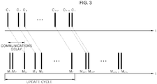
- FIG. 3 is a diagram showing n charging/discharging reference values and (n + k) charging/discharging power values stored in the storage unit 110 of the apparatus for updating charging/discharging efficiency factors of the energy storage system according to the exemplary embodiment of the present disclosure.
- the storage unit 110 may store n charging/discharging reference values input to the ESS 10 during a predetermined update cycle, where n is a natural number.
- the charging/discharging reference values may be power values for setting the amount of power discharged from or charged in the ESS 10.
- the number n of charging/discharging reference values stored in the storage unit 110 may vary depending on the operating environment of the ESS 10.
- the apparatus 100 may receive charging/discharging reference values input to the ESS 10 from a control unit for controlling the charging/discharging of the ESS 10.
- the storage unit 110 may store (n + k) charging/discharging power values measured in the ESS 10 after the predetermined update cycle has started, where k is a natural number.
- the charging/discharging power values may be actually measured amounts of power discharged from or charged in the ESS 10.
- the apparatus 100 may receive charging/discharging power values from a power measuring unit for measuring the charging/discharging power of the ESS 10.
- the storage unit 110 may store the n charging/discharging reference values during the predetermined update cycle, as well as the charging/discharging power values stored after the predetermined update cycle has started until the number of stored charging/discharging power values becomes (n + k).
- the number of charging/discharging power values is larger than that of the charging/discharging reference values by k.
- the number of the charging/discharging power values is larger than that of the charging/discharging reference values by k in the storage unit 100 because a charging/discharging power value corresponding to a charging/discharging reference value may be measured in the ESS 10 after a communications delay occurring when the charging/discharging reference value is input to the ESS 10.
- the charging/discharging power value corresponding to the first charging/discharging reference value C1 is not the first charging/discharging power value M1 but the third charging/discharging power value M3 measured after the communication delay time from the time point at which the first charging/discharging reference C1 is input.
- the storage unit 110 may store the (n + k) charging/discharging power values for the n charging/discharging reference values input to the ESS 10.
- the correlation coefficient calculation unit 120 may calculate correlation coefficients between the n charging/discharging reference values and the (n + k) charging/discharging power values stored in the storage unit 110.
- the correlation coefficient calculation unit 120 may sort the (n + k) charging/discharging power values into groups each including n charging/discharging power values based on measured time points, and may calculate correlation coefficients between the n charging/discharging reference values and the n charging/discharging power values in each of the groups.
- the correlation coefficient calculation unit 120 may sort the (n + k) charging/discharging power values into groups including: a group of the first to n th charging/discharging power values, a group of the second to (n + 1) th charging/discharging power values, and a group of the third to the (n + 2) th charging/discharging power values.
- the correlation coefficient calculation unit 120 may calculate the correlation coefficients between each of the first to n th charging/discharging power values, the second to the (n + 1) th charging/discharging power values and the third to the (n + 2) th charging/discharging power values, and the n charging/discharging reference values.
- the correlation coefficient calculation unit 120 may calculate correlation coefficients between the first to the n th charging/discharging power values and the n charging/discharging reference values, correlation coefficients between the second to the (n + 1) charging/discharging power values and the n charging/discharging reference values, and correlation coefficients between the third to the (n + 2) th charging/discharging power values and the n the charging/discharging reference values.
- R CM,y denotes correlation coefficient
- Cx denotes the charging/discharging reference value
- a C,y denotes average value of charging/discharging reference values
- M x+y denotes charging/discharging power value
- a M,y denotes average value of the charging/discharging power values
- S C,y denotes standard deviation of charging/discharging reference values
- S M,y denotes standard deviation of charging/discharging power values, where y ranges from 0 to k.
- the selection unit 130 may select n charging/discharging power values corresponding to the n charging/discharging reference values among the (n + k) charging/discharging power values based on the correlation coefficients calculated from the correlation coefficient calculation unit 120.
- the selection unit 130 may select the group of the n charging/discharging power values with the largest correlation coefficient among the (n + k) charging/discharging power values.
- the correlation coefficient calculation unit 120 may calculate the correlation coefficients between each of the first to n th charging/discharging power values, the second to the (n + 1) th charging/discharging power values and the third to the (n + 2) th charging/discharging power values, and the n charging/discharging reference values.
- the selection unit 130 may compare correlation coefficients between the first to the n th charging/discharging power values and the n charging/discharging reference values, correlation coefficients between the second to the (n + 1) charging/discharging power values and the n charging/discharging reference values, and correlation coefficients between the third to the (n + 2) th charging/discharging power values and the n the charging/discharging reference values, and may select the largest correlation coefficient.
- the selection unit 130 selects the third to the (n + 2) th charging/discharging power values as the charging/discharging power values corresponding to n charging/discharging reference values.
- the selection unit 130 may calculate a time difference between the time point of the earliest one of the charging/discharging power values among the n selected charging/discharging power values and time point of the earliest one of the charging/discharging reference values among the n charging/discharging reference values, as the communications delay time.
- the efficiency factor calculation unit 140 may calculate the ratio between the n charging/discharging reference values and the n charging/discharging power values selected from the selection unit 130 as n charging/discharging efficiency factors.
- the selection unit 130 selects the third to the (n + 2) th charging/discharging power values among the (n + k) charging/discharging power values as ones corresponding to the n charging/discharging reference values, as shown in Table 2, the ratio between the n charging/discharging reference values and the third to the (n +2) th charging/discharging power values may be calculated as the n charging/discharging efficiency factors.
- Charging/discharging reference value Charging/discharging power value Charging/discharging efficiency First Third E1 Second Fourth E2 ⁇ ⁇ n th (n + 2) th En
- the update unit 150 may update the charging/discharging efficiency factors set for each power range with the n charging/discharging efficiency factors calculated from the efficiency factor calculation unit 140.
- the update unit 150 may update the charging/discharging efficiency factors of the power range included the n charging/discharging reference values used for calculating the n charging/discharging efficiency factors with the charging/discharging efficiency factors calculated from the calculation unit 140.
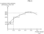
- the update unit 150 may update the charging/discharging efficiency of 35% of the power range including the first charging/discharging reference value of 0.15 MW to 32%.
- Power range Charging/discharging efficiency factor 0.0 to 0.2 MW 35% 0.2 to 0.4 MW 63% 0.4 to 0.6 MW 80% 0.6 to 0.8 MW 92% 0.8 to 1.0 MW 88%
- the update unit 150 updates the predetermined charging/discharging efficiency factors with the charging/discharging efficiency factors calculated from the efficiency factor calculation unit 140 so that the power close to the target charging/discharging value required by the ESS is charged/discharged, thereby improving the accuracy of the charging/discharging reference values.
- the manager can check the charging/discharging efficiency factors accurately, and accordingly the energy storage system can be managed more efficiently.
Landscapes
- Engineering & Computer Science (AREA)
- Power Engineering (AREA)
- Physics & Mathematics (AREA)
- General Physics & Mathematics (AREA)
- Charge And Discharge Circuits For Batteries Or The Like (AREA)
- Supply And Distribution Of Alternating Current (AREA)
- Management, Administration, Business Operations System, And Electronic Commerce (AREA)
Abstract
Description
- The present disclosure relates to an apparatus for updating charging/discharging efficiency factors of an energy storage system, and more particularly, to an apparatus for updating charging/discharging efficiency factors of an energy storage system that updates, in real-time, charging/discharging efficiency factors for correcting charging/discharging reference values applied to the energy storage system.
- An Energy Storage System (ESS) stores generated power in linked systems including power plants, substations, transmission lines, etc. and then uses energy selectively and efficiently when necessary, to thereby increase the energy efficiency.
- The ESS can reduce the deviations in electrical loads depending on time zones and seasons, thereby improving the overall load to lower the cost of generating electric power. Accordingly, the investment cost and operating cost required for expanding electric power facility can be reduced, such that electricity rates can be lowered and the energy can be saved.
- Such ESSs are installed in power generation, transmission, distribution, and customers in power systems. They are used for frequency regulation, generator output stabilization using new and renewable energy, peak shaving, load leveling, emergency power, and so on.
- ESSs are divided into physical energy storage and chemical energy storage depending on the storage manner. Physical energy storage includes method using pumped storage generation, compressed air storage, and flywheels. Chemical energy storage includes method using lithium ion batteries, lead acid batteries, and NaS batteries.
-
FIG. 1 is a flowchart for illustrating a process of charging/discharging electric power in a conventional ESS. - Referring to
FIG. 1 , for charging power to the ESS or outputting the power stored in the ESS, the power range including the target charging/discharging value required by the ESS is checked (step S1). - However, when the charging/discharging reference value equal to the target charging/discharging value required by the ESS is input from an external source to the ESS, a charging/discharging power different from the input charging/discharging reference value may be output or charged due to various conditions such as the operating environment of the ESS, deterioration of the secondary battery included in the ESS, power condition of the power system, etc.
- To avoid this, the conventional ESS sets and stores the charging/discharging efficiency factors for correcting the charging/discharging reference values for each power range of the target charging/discharging values. Then, in the conventional ESS, the charging/discharging reference value is calculated using the charging/discharging efficiency factors of the power range including the target charging/discharging value determined in step S1 (step S2).
- Subsequently, the conventional ESS charges electric power or outputs stored electric power based on the calculated charging/discharging reference value (step S3).
- However, the conventional ESS uses the initially set charging/discharging efficiency factors without updating. Thus, there is a problem that an error is increased between the charging/discharging reference value and the electric power actually charged or discharged in the ESS as the operating environment changes such as deterioration of the secondary battery included in the ESS.
- It is an object of the present disclosure to provide an apparatus for updating charging/discharging efficiency factors of an energy storage system, which calculate correlation coefficients between n charging/discharging reference values input to the energy storage system during a predetermined update cycle and (n + k) charging/discharging power values measured in the energy storage system after the predetermined update cycle has started, where n and k are natural numbers, selects n charging/discharging power values corresponding to the n charging/discharging reference values among the (n + k) charging/discharging power values based on correlation coefficients, and updates the charging/discharging efficiency factors set for each power range with n charging/discharging efficiency factors calculated by using the n charging/discharging reference values and the selected n charging/discharging power values.
- Objects of the present disclosure are not limited to the above-described objects and other objects and advantages can be appreciated by those skilled in the art from the following descriptions. Further, it will be easily appreciated that the objects and advantages of the present disclosure can be practiced by means recited in the appended claims and a combination thereof.
- In accordance with one aspect of the present disclosure, an apparatus for updating charging/discharging efficiency factors of an energy storage system includes: a correlation coefficient calculate unit configured to calculate correlation coefficients between n charging/discharging reference values input to the energy storage system during a predetermined update cycle and (n + k) charging/discharging power values measured in the energy storage system after the predetermined update cycle has started, where n and k are natural numbers; a selection unit configured to n charging/discharging power values corresponding to the n charging/discharging reference values among the (n + k) charging/discharging power values based on correlation coefficients; and an update unit configured to update the charging/discharging efficiency factors set for each power range with n charging/discharging efficiency factors calculated by using the n charging/discharging reference values and the selected n charging/discharging power values.
- According to an exemplary embodiment of the present disclosure, charging/discharging efficiency factors of an energy storage system can be updated in real-time, by calculating correlation coefficients between n charging/discharging reference values input to the energy storage system during a predetermined update cycle and (n + k) charging/discharging power values measured in the energy storage system after the predetermined update cycle has started, where n and k are natural numbers, by selecting n charging/discharging power values corresponding to the n charging/discharging reference values among the (n + k) charging/discharging power values based on correlation coefficients, and by updating the charging/discharging efficiency factors set for each power range with n charging/discharging efficiency factors calculated by using the n charging/discharging reference values and the selected n charging/discharging power values.
- Also, it is possible to reduce the error between the charging/discharging reference values and the power actually charged or discharged in the ESS due to the change of the operating environment. In addition, the manager can check the charging/discharging efficiency factors accurately, and accordingly the energy storage system can be managed more efficiently.
-
-
FIG. 1 is a flowchart for illustrating a process of charging/discharging electric power in a conventional ESS; -
FIG. 2 is a block diagram illustrating a configuration of an apparatus for updating charging/discharging efficiency factors of an energy storage system according to an exemplary embodiment of the present disclosure in detail; -
FIG. 3 is a diagram showing n charging/discharging reference values and (n + k) charging/discharging power values stored in a storage unit of an apparatus for updating charging/discharging efficiency factors of an energy storage system according to an exemplary embodiment of the present disclosure; and -
FIG. 4 is a graph showing charging/discharging efficiency factors for each power range updated by the apparatus for updating charging/discharging efficiency factors of an energy storage system according to an exemplary embodiment of the present disclosure. - The above objects, features and advantages will become apparent from the detailed description with reference to the accompanying drawings. Embodiments are described in sufficient detail to enable those skilled in the art in the art to easily practice the technical idea of the present disclosure. Detailed descriptions of well known functions or configurations may be omitted in order not to unnecessarily obscure the gist of the present disclosure. Hereinafter, embodiments of the present disclosure will be described in detail with reference to the accompanying drawings. Throughout the drawings, like reference numerals refer to like elements.
-
FIG. 2 is a block diagram illustrating a configuration of anapparatus 100 for updating charging/discharging efficiency factors of an energy storage system according to an exemplary embodiment of the present disclosure in detail. - Referring to
FIG. 2 , theapparatus 100 for updating charging/discharging efficiency factors of an energy storage system according to the exemplary embodiment of the present disclosure includes astorage unit 110, a correlationcoefficient calculation unit 120, aselection unit 130, an efficiencyfactor calculation unit 140, and anupdate unit 150. Theapparatus 100 shown inFIG. 2 is merely an exemplary embodiment of the present disclosure, and the elements are not limited to those shown inFIG. 2 . Some elements may be added, modified or eliminated as desired. -
FIG. 3 is a diagram showing n charging/discharging reference values and (n + k) charging/discharging power values stored in thestorage unit 110 of the apparatus for updating charging/discharging efficiency factors of the energy storage system according to the exemplary embodiment of the present disclosure. - Referring to
FIG. 3 , thestorage unit 110 may store n charging/discharging reference values input to theESS 10 during a predetermined update cycle, where n is a natural number. - As used herein, the charging/discharging reference values may be power values for setting the amount of power discharged from or charged in the
ESS 10. - The number n of charging/discharging reference values stored in the
storage unit 110 may vary depending on the operating environment of theESS 10. - To this end, the
apparatus 100 may receive charging/discharging reference values input to theESS 10 from a control unit for controlling the charging/discharging of theESS 10. - In addition, the
storage unit 110 may store (n + k) charging/discharging power values measured in theESS 10 after the predetermined update cycle has started, where k is a natural number. - As used herein, the charging/discharging power values may be actually measured amounts of power discharged from or charged in the
ESS 10. - To this end, the
apparatus 100 may receive charging/discharging power values from a power measuring unit for measuring the charging/discharging power of theESS 10. - That is, the
storage unit 110 may store the n charging/discharging reference values during the predetermined update cycle, as well as the charging/discharging power values stored after the predetermined update cycle has started until the number of stored charging/discharging power values becomes (n + k). - Accordingly, in the
storage unit 110, the number of charging/discharging power values is larger than that of the charging/discharging reference values by k. - The number of the charging/discharging power values is larger than that of the charging/discharging reference values by k in the
storage unit 100 because a charging/discharging power value corresponding to a charging/discharging reference value may be measured in theESS 10 after a communications delay occurring when the charging/discharging reference value is input to theESS 10. - Accordingly, as shown in
FIG. 3 , the charging/discharging power value corresponding to the first charging/discharging reference value C1 is not the first charging/discharging power value M1 but the third charging/discharging power value M3 measured after the communication delay time from the time point at which the first charging/discharging reference C1 is input. - For this reason, the
storage unit 110 may store the (n + k) charging/discharging power values for the n charging/discharging reference values input to theESS 10. - The correlation
coefficient calculation unit 120 may calculate correlation coefficients between the n charging/discharging reference values and the (n + k) charging/discharging power values stored in thestorage unit 110. - More specifically, the correlation
coefficient calculation unit 120 may sort the (n + k) charging/discharging power values into groups each including n charging/discharging power values based on measured time points, and may calculate correlation coefficients between the n charging/discharging reference values and the n charging/discharging power values in each of the groups. - For example, when k is 2, the correlation
coefficient calculation unit 120 may sort the (n + k) charging/discharging power values into groups including: a group of the first to nth charging/discharging power values, a group of the second to (n + 1)th charging/discharging power values, and a group of the third to the (n + 2)th charging/discharging power values. - Subsequently, the correlation
coefficient calculation unit 120 may calculate the correlation coefficients between each of the first to nth charging/discharging power values, the second to the (n + 1)th charging/discharging power values and the third to the (n + 2)th charging/discharging power values, and the n charging/discharging reference values. - Accordingly, the correlation
coefficient calculation unit 120 may calculate correlation coefficients between the first to the nth charging/discharging power values and the n charging/discharging reference values, correlation coefficients between the second to the (n + 1) charging/discharging power values and the n charging/discharging reference values, and correlation coefficients between the third to the (n + 2)th charging/discharging power values and the n the charging/discharging reference values.[Table 1] Charging/discharging reference value Charging/discharging power value Correlation coefficient First to nth First to nth RCM,0 First to nth Second to (n + 1)th RCM,1 First to nth Third to (n + 2)th RCM,2 - The correlation
coefficient calculation unit 120 may calculate the correlationcoefficients using Equation 1 below:
- The
selection unit 130 may select n charging/discharging power values corresponding to the n charging/discharging reference values among the (n + k) charging/discharging power values based on the correlation coefficients calculated from the correlationcoefficient calculation unit 120. - More specifically, the
selection unit 130 may select the group of the n charging/discharging power values with the largest correlation coefficient among the (n + k) charging/discharging power values. - When k is 1 as described above, the correlation
coefficient calculation unit 120 may calculate the correlation coefficients between each of the first to nth charging/discharging power values, the second to the (n + 1)th charging/discharging power values and the third to the (n + 2)th charging/discharging power values, and the n charging/discharging reference values. - The
selection unit 130 may compare correlation coefficients between the first to the nth charging/discharging power values and the n charging/discharging reference values, correlation coefficients between the second to the (n + 1) charging/discharging power values and the n charging/discharging reference values, and correlation coefficients between the third to the (n + 2)th charging/discharging power values and the n the charging/discharging reference values, and may select the largest correlation coefficient. - Then, if the correlation coefficient between the third to the (n + 2)th charging/discharging power values and the n charging/discharging reference values is selected as the largest correlation coefficient, the
selection unit 130 selects the third to the (n + 2)th charging/discharging power values as the charging/discharging power values corresponding to n charging/discharging reference values. - In addition, the
selection unit 130 may calculate a time difference between the time point of the earliest one of the charging/discharging power values among the n selected charging/discharging power values and time point of the earliest one of the charging/discharging reference values among the n charging/discharging reference values, as the communications delay time. - The efficiency
factor calculation unit 140 may calculate the ratio between the n charging/discharging reference values and the n charging/discharging power values selected from theselection unit 130 as n charging/discharging efficiency factors. - For example, when the
selection unit 130 selects the third to the (n + 2)th charging/discharging power values among the (n + k) charging/discharging power values as ones corresponding to the n charging/discharging reference values, as shown in Table 2, the ratio between the n charging/discharging reference values and the third to the (n +2)th charging/discharging power values may be calculated as the n charging/discharging efficiency factors.[Table 2] Charging/discharging reference value Charging/discharging power value Charging/discharging efficiency First Third E1 Second Fourth E2 ··· ··· ··· nth (n + 2)th En - The efficiency
factor calculation unit 140 may update the charging/discharging efficiency factors of the energy storagesystem using Equation 2 below:
- The
update unit 150 may update the charging/discharging efficiency factors set for each power range with the n charging/discharging efficiency factors calculated from the efficiencyfactor calculation unit 140. - For example, as shown in Table 3 and
FIG. 4 , when thestorage unit 110 stores charging/discharging efficiency factors set every 0.2 MW, theupdate unit 150 may update the charging/discharging efficiency factors of the power range included the n charging/discharging reference values used for calculating the n charging/discharging efficiency factors with the charging/discharging efficiency factors calculated from thecalculation unit 140. - For example, when the first charging/discharging reference value calculated from the efficiency
factor calculation unit 140 is 30% and the first charging/discharging reference value used to calculate the first charging/discharging reference value is 0.15 MW, theupdate unit 150 may update the charging/discharging efficiency of 35% of the power range including the first charging/discharging reference value of 0.15 MW to 32%.[Table 3] Power range Charging/discharging efficiency factor 0.0 to 0.2 MW 35% 0.2 to 0.4 MW 63% 0.4 to 0.6 MW 80% 0.6 to 0.8 MW 92% 0.8 to 1.0 MW 88% - Accordingly, the
update unit 150 updates the predetermined charging/discharging efficiency factors with the charging/discharging efficiency factors calculated from the efficiencyfactor calculation unit 140 so that the power close to the target charging/discharging value required by the ESS is charged/discharged, thereby improving the accuracy of the charging/discharging reference values. - Also, it is possible to reduce the error between the charging/discharging reference values and the power actually charged or discharged in the ESS due to the change of the operating environment. In addition, the manager can check the charging/discharging efficiency factors accurately, and accordingly the energy storage system can be managed more efficiently.
- The present disclosure described above may be variously substituted, altered, and modified by those skilled in the art to which the present invention pertains without departing from the scope and sprit of the present disclosure. Therefore, the present disclosure is not limited to the above-mentioned exemplary embodiments and the accompanying drawings.
Claims (7)
- An apparatus (100) for updating charging/discharging efficiency factors of an energy storage system (ESS; 10), the apparatus (100) comprising:a correlation coefficient calculation unit (120) configured to calculate correlation coefficients between n charging/discharging reference values input to the ESS (10) during a predetermined update cycle and (n + k) charging/discharging power values measured in the ESS (10) after the predetermined update cycle has started, where n and k are natural numbers;a selection unit (130) configured to select n charging/discharging power values corresponding to the n charging/discharging reference values among the (n + k) charging/discharging power values based on the correlation coefficients; andan update unit (150) configured to update the charging/discharging efficiency factors set for each power range with n charging/discharging efficiency factors calculated by using the n charging/discharging reference values and the selected n charging/discharging power values.
- The apparatus of claim 1, wherein the correlation coefficient calculation unit (120) sorts the (n + k) charging/discharging power values into groups each including n charging/discharging power values based on measured time points, and calculates correlation coefficients between the n charging/discharging reference values and the n charging/discharging power values in each of the groups.
- The apparatus of claim 1 or 2, wherein the correlation coefficient calculation unit (120) calculates the correlation coefficients by using:

- The apparatus of any one of claims 1 to 3, wherein the selection unit (130) selects n charging/discharging power values with a largest correlation coefficient from among the (n + k) charging/discharging power values.
- The apparatus of any one of claims 1 to 3, wherein the selection unit 130 calculates a time difference between a time point of the earliest one of the n selected charging/discharging power values and a time point of the earliest one of the n charging/discharging reference values, as a communications delay time.
- The apparatus of any one of claims 1 to 5, further comprising: an efficiency factor calculation unit (140) configured to calculate ratios between the n charging/discharging reference values and the n selected charging/discharging power values as the n charging/discharging efficiency factors.
- The apparatus of claim 6, wherein the efficiency factor calculation unit (140) calculates the n charging/discharging efficiency factors by using:

Applications Claiming Priority (1)
| Application Number | Priority Date | Filing Date | Title |
|---|---|---|---|
| KR1020160173975A KR102464753B1 (en) | 2016-12-19 | 2016-12-19 | Apparatus for updating charging/discharging efficiency factor of energy storage system |
Publications (2)
| Publication Number | Publication Date |
|---|---|
| EP3337004A1 true EP3337004A1 (en) | 2018-06-20 |
| EP3337004B1 EP3337004B1 (en) | 2019-03-06 |
Family
ID=58401427
Family Applications (1)
| Application Number | Title | Priority Date | Filing Date |
|---|---|---|---|
| EP17162091.7A Not-in-force EP3337004B1 (en) | 2016-12-19 | 2017-03-21 | Apparatus for updating charging/discharging efficiency factor of energy storage system |
Country Status (6)
| Country | Link |
|---|---|
| US (1) | US10330733B2 (en) |
| EP (1) | EP3337004B1 (en) |
| JP (1) | JP6276445B1 (en) |
| KR (1) | KR102464753B1 (en) |
| CN (1) | CN108206561B (en) |
| ES (1) | ES2724477T3 (en) |
Families Citing this family (1)
| Publication number | Priority date | Publication date | Assignee | Title |
|---|---|---|---|---|
| CN111413630B (en) * | 2020-03-11 | 2022-06-14 | 合肥国轩高科动力能源有限公司 | Pulse discharge power correction method for lithium battery |
Citations (2)
| Publication number | Priority date | Publication date | Assignee | Title |
|---|---|---|---|---|
| CA2157642A1 (en) * | 1994-09-06 | 1996-03-07 | Richard L. Proctor | Power conversion equipment monitor/controller method and apparatus |
| EP2933896A1 (en) * | 2012-12-14 | 2015-10-21 | Panasonic Corporation | Charging and discharging control method, charging and discharging control system and charging and discharging control device |
Family Cites Families (14)
| Publication number | Priority date | Publication date | Assignee | Title |
|---|---|---|---|---|
| JPH0620723A (en) * | 1992-07-07 | 1994-01-28 | Fujitsu Ltd | Secondary battery residual quantity display device and display method |
| JP3697897B2 (en) * | 1998-06-17 | 2005-09-21 | 日産自動車株式会社 | Battery capacity meter controller |
| JP2001339863A (en) | 2000-05-30 | 2001-12-07 | Sanyo Electric Co Ltd | Calculation method of remaining capacity of secondary battery |
| JP4256833B2 (en) | 2004-11-10 | 2009-04-22 | 三菱重工業株式会社 | Power storage device and hybrid distributed power supply system |
| WO2011030380A1 (en) | 2009-09-10 | 2011-03-17 | 株式会社日立エンジニアリング・アンド・サービス | Power storage device for electric power generation system and method for operating the power storage device |
| KR20130091951A (en) * | 2012-02-09 | 2013-08-20 | 삼성에스디아이 주식회사 | Battery pack, controlling method of the same, and power storage system including the battery pack |
| US20140095088A1 (en) * | 2012-09-28 | 2014-04-03 | Caterpillar Inc. | Systems and methods for characterization of energy storage devices |
| AU2014241787B2 (en) * | 2013-03-14 | 2016-07-28 | Allison Transmission, Inc. | System and method for power management during regeneration mode in hybrid electric vehicles |
| KR101563062B1 (en) | 2013-12-31 | 2015-10-23 | 주식회사 포스코아이씨티 | Battery Energy Storage System and Method for Controlling Battery Energy Storage System |
| TW201547148A (en) * | 2014-03-04 | 2015-12-16 | 日揮股份有限公司 | Power Systems |
| KR101595801B1 (en) | 2014-04-21 | 2016-02-19 | 디아이케이(주) | Energy Storage System for parallel driving and driving method thereof |
| JP6494923B2 (en) | 2014-05-12 | 2019-04-03 | カルソニックカンセイ株式会社 | Charging rate detection apparatus and charging rate detection method |
| JP6564647B2 (en) * | 2015-01-30 | 2019-08-21 | 大和製罐株式会社 | Battery degradation state estimation device and degradation state estimation method thereof |
| US10622940B2 (en) * | 2015-12-18 | 2020-04-14 | Locus Energy, Inc. | Time interval production measurement and energy storage performance analytics in renewable DC energy systems |
-
2016
- 2016-12-19 KR KR1020160173975A patent/KR102464753B1/en active Active
-
2017
- 2017-03-21 EP EP17162091.7A patent/EP3337004B1/en not_active Not-in-force
- 2017-03-21 ES ES17162091T patent/ES2724477T3/en active Active
- 2017-03-23 US US15/468,023 patent/US10330733B2/en active Active
- 2017-03-23 JP JP2017058037A patent/JP6276445B1/en active Active
- 2017-03-30 CN CN201710202084.0A patent/CN108206561B/en active Active
Patent Citations (2)
| Publication number | Priority date | Publication date | Assignee | Title |
|---|---|---|---|---|
| CA2157642A1 (en) * | 1994-09-06 | 1996-03-07 | Richard L. Proctor | Power conversion equipment monitor/controller method and apparatus |
| EP2933896A1 (en) * | 2012-12-14 | 2015-10-21 | Panasonic Corporation | Charging and discharging control method, charging and discharging control system and charging and discharging control device |
Also Published As
| Publication number | Publication date |
|---|---|
| EP3337004B1 (en) | 2019-03-06 |
| CN108206561A (en) | 2018-06-26 |
| JP6276445B1 (en) | 2018-02-07 |
| CN108206561B (en) | 2021-05-28 |
| KR102464753B1 (en) | 2022-11-07 |
| KR20180071133A (en) | 2018-06-27 |
| US10330733B2 (en) | 2019-06-25 |
| JP2018102109A (en) | 2018-06-28 |
| US20180172774A1 (en) | 2018-06-21 |
| ES2724477T3 (en) | 2019-09-11 |
Similar Documents
| Publication | Publication Date | Title |
|---|---|---|
| CN105891730B (en) | A kind of computational methods of automobile power cell capacity | |
| US9711976B2 (en) | Lead storage battery system | |
| US12584971B2 (en) | Battery management apparatus, battery management method, and battery energy storage system | |
| US11054475B2 (en) | Electric storage capacity estimation apparatus and method for operating the same | |
| AU2018282349B2 (en) | Method for charging an energy store of a vehicle using a modular charging apparatus with high overall efficiency | |
| JPWO2019016998A1 (en) | Storage battery system charge control device, storage battery system and storage battery charge control method | |
| US10297877B2 (en) | Storage battery control device and storage battery control method | |
| US11146075B2 (en) | Charge/discharge control apparatus and method of energy storage system, and energy charge/discharge control system and method | |
| KR20180047179A (en) | Method for proctect overcharg, overdischargge and efficiency increasing of battery pack | |
| KR20160029741A (en) | Apparatus and method for managing stored energy | |
| US9882409B2 (en) | System and method for correcting SOC of battery | |
| US10054645B2 (en) | Deterioration determination method, deterioration determination device, and storage medium | |
| CN117154268B (en) | SOC correction method, device and equipment based on water system sodium ion energy storage battery cabinet and storage medium | |
| US11876435B2 (en) | DC/DC conversion system, electricity storage system, and method for controlling DC/DC converter | |
| CN105728352A (en) | Battery sorting method | |
| JP2012016077A (en) | Frequency control apparatus in power system | |
| JP6826152B2 (en) | Secondary battery charge status estimation method and estimation device | |
| CN107482269A (en) | Discharging control method and device of power battery, controller and automobile | |
| KR101689017B1 (en) | System and method for fuzzy droop control of multi-bess in microgrid | |
| CN110969305A (en) | Photovoltaic power station simulation model parameter optimization method and system | |
| KR20180101823A (en) | Apparatus and method for processing voltage data of battery cell | |
| JP2014236600A (en) | Controller for a plurality of purposes of circuit storage battery | |
| JP2016162559A (en) | Secondary battery inspection method | |
| CN108132441A (en) | The range of operation of energy-storage battery module state-of-charge determines method and device | |
| EP3337004B1 (en) | Apparatus for updating charging/discharging efficiency factor of energy storage system |
Legal Events
| Date | Code | Title | Description |
|---|---|---|---|
| PUAI | Public reference made under article 153(3) epc to a published international application that has entered the european phase |
Free format text: ORIGINAL CODE: 0009012 |
|
| STAA | Information on the status of an ep patent application or granted ep patent |
Free format text: STATUS: REQUEST FOR EXAMINATION WAS MADE |
|
| 17P | Request for examination filed |
Effective date: 20180226 |
|
| AK | Designated contracting states |
Kind code of ref document: A1 Designated state(s): AL AT BE BG CH CY CZ DE DK EE ES FI FR GB GR HR HU IE IS IT LI LT LU LV MC MK MT NL NO PL PT RO RS SE SI SK SM TR |
|
| AX | Request for extension of the european patent |
Extension state: BA ME |
|
| STAA | Information on the status of an ep patent application or granted ep patent |
Free format text: STATUS: EXAMINATION IS IN PROGRESS |
|
| 17Q | First examination report despatched |
Effective date: 20180620 |
|
| REG | Reference to a national code |
Ref country code: DE Ref legal event code: R079 Ref document number: 602017002429 Country of ref document: DE Free format text: PREVIOUS MAIN CLASS: H02J0007000000 Ipc: G01R0031360000 |
|
| GRAP | Despatch of communication of intention to grant a patent |
Free format text: ORIGINAL CODE: EPIDOSNIGR1 |
|
| STAA | Information on the status of an ep patent application or granted ep patent |
Free format text: STATUS: GRANT OF PATENT IS INTENDED |
|
| RIC1 | Information provided on ipc code assigned before grant |
Ipc: H02J 7/04 20060101ALI20180831BHEP Ipc: G01R 31/36 20060101AFI20180831BHEP Ipc: H02J 7/00 20060101ALI20180831BHEP |
|
| INTG | Intention to grant announced |
Effective date: 20180919 |
|
| GRAS | Grant fee paid |
Free format text: ORIGINAL CODE: EPIDOSNIGR3 |
|
| GRAA | (expected) grant |
Free format text: ORIGINAL CODE: 0009210 |
|
| STAA | Information on the status of an ep patent application or granted ep patent |
Free format text: STATUS: THE PATENT HAS BEEN GRANTED |
|
| AK | Designated contracting states |
Kind code of ref document: B1 Designated state(s): AL AT BE BG CH CY CZ DE DK EE ES FI FR GB GR HR HU IE IS IT LI LT LU LV MC MK MT NL NO PL PT RO RS SE SI SK SM TR |
|
| REG | Reference to a national code |
Ref country code: GB Ref legal event code: FG4D |
|
| REG | Reference to a national code |
Ref country code: CH Ref legal event code: EP Ref country code: AT Ref legal event code: REF Ref document number: 1105273 Country of ref document: AT Kind code of ref document: T Effective date: 20190315 |
|
| REG | Reference to a national code |
Ref country code: DE Ref legal event code: R096 Ref document number: 602017002429 Country of ref document: DE |
|
| REG | Reference to a national code |
Ref country code: IE Ref legal event code: FG4D |
|
| REG | Reference to a national code |
Ref country code: NL Ref legal event code: MP Effective date: 20190306 |
|
| REG | Reference to a national code |
Ref country code: LT Ref legal event code: MG4D |
|
| PG25 | Lapsed in a contracting state [announced via postgrant information from national office to epo] |
Ref country code: SE Free format text: LAPSE BECAUSE OF FAILURE TO SUBMIT A TRANSLATION OF THE DESCRIPTION OR TO PAY THE FEE WITHIN THE PRESCRIBED TIME-LIMIT Effective date: 20190306 Ref country code: LT Free format text: LAPSE BECAUSE OF FAILURE TO SUBMIT A TRANSLATION OF THE DESCRIPTION OR TO PAY THE FEE WITHIN THE PRESCRIBED TIME-LIMIT Effective date: 20190306 Ref country code: FI Free format text: LAPSE BECAUSE OF FAILURE TO SUBMIT A TRANSLATION OF THE DESCRIPTION OR TO PAY THE FEE WITHIN THE PRESCRIBED TIME-LIMIT Effective date: 20190306 Ref country code: NO Free format text: LAPSE BECAUSE OF FAILURE TO SUBMIT A TRANSLATION OF THE DESCRIPTION OR TO PAY THE FEE WITHIN THE PRESCRIBED TIME-LIMIT Effective date: 20190606 |
|
| PG25 | Lapsed in a contracting state [announced via postgrant information from national office to epo] |
Ref country code: BG Free format text: LAPSE BECAUSE OF FAILURE TO SUBMIT A TRANSLATION OF THE DESCRIPTION OR TO PAY THE FEE WITHIN THE PRESCRIBED TIME-LIMIT Effective date: 20190606 Ref country code: RS Free format text: LAPSE BECAUSE OF FAILURE TO SUBMIT A TRANSLATION OF THE DESCRIPTION OR TO PAY THE FEE WITHIN THE PRESCRIBED TIME-LIMIT Effective date: 20190306 Ref country code: LV Free format text: LAPSE BECAUSE OF FAILURE TO SUBMIT A TRANSLATION OF THE DESCRIPTION OR TO PAY THE FEE WITHIN THE PRESCRIBED TIME-LIMIT Effective date: 20190306 Ref country code: NL Free format text: LAPSE BECAUSE OF FAILURE TO SUBMIT A TRANSLATION OF THE DESCRIPTION OR TO PAY THE FEE WITHIN THE PRESCRIBED TIME-LIMIT Effective date: 20190306 Ref country code: GR Free format text: LAPSE BECAUSE OF FAILURE TO SUBMIT A TRANSLATION OF THE DESCRIPTION OR TO PAY THE FEE WITHIN THE PRESCRIBED TIME-LIMIT Effective date: 20190607 Ref country code: HR Free format text: LAPSE BECAUSE OF FAILURE TO SUBMIT A TRANSLATION OF THE DESCRIPTION OR TO PAY THE FEE WITHIN THE PRESCRIBED TIME-LIMIT Effective date: 20190306 |
|
| REG | Reference to a national code |
Ref country code: ES Ref legal event code: FG2A Ref document number: 2724477 Country of ref document: ES Kind code of ref document: T3 Effective date: 20190911 |
|
| REG | Reference to a national code |
Ref country code: AT Ref legal event code: MK05 Ref document number: 1105273 Country of ref document: AT Kind code of ref document: T Effective date: 20190306 |
|
| PG25 | Lapsed in a contracting state [announced via postgrant information from national office to epo] |
Ref country code: AL Free format text: LAPSE BECAUSE OF FAILURE TO SUBMIT A TRANSLATION OF THE DESCRIPTION OR TO PAY THE FEE WITHIN THE PRESCRIBED TIME-LIMIT Effective date: 20190306 Ref country code: PT Free format text: LAPSE BECAUSE OF FAILURE TO SUBMIT A TRANSLATION OF THE DESCRIPTION OR TO PAY THE FEE WITHIN THE PRESCRIBED TIME-LIMIT Effective date: 20190706 Ref country code: SK Free format text: LAPSE BECAUSE OF FAILURE TO SUBMIT A TRANSLATION OF THE DESCRIPTION OR TO PAY THE FEE WITHIN THE PRESCRIBED TIME-LIMIT Effective date: 20190306 Ref country code: EE Free format text: LAPSE BECAUSE OF FAILURE TO SUBMIT A TRANSLATION OF THE DESCRIPTION OR TO PAY THE FEE WITHIN THE PRESCRIBED TIME-LIMIT Effective date: 20190306 Ref country code: RO Free format text: LAPSE BECAUSE OF FAILURE TO SUBMIT A TRANSLATION OF THE DESCRIPTION OR TO PAY THE FEE WITHIN THE PRESCRIBED TIME-LIMIT Effective date: 20190306 Ref country code: CZ Free format text: LAPSE BECAUSE OF FAILURE TO SUBMIT A TRANSLATION OF THE DESCRIPTION OR TO PAY THE FEE WITHIN THE PRESCRIBED TIME-LIMIT Effective date: 20190306 |
|
| PG25 | Lapsed in a contracting state [announced via postgrant information from national office to epo] |
Ref country code: SM Free format text: LAPSE BECAUSE OF FAILURE TO SUBMIT A TRANSLATION OF THE DESCRIPTION OR TO PAY THE FEE WITHIN THE PRESCRIBED TIME-LIMIT Effective date: 20190306 Ref country code: LU Free format text: LAPSE BECAUSE OF NON-PAYMENT OF DUE FEES Effective date: 20190321 Ref country code: PL Free format text: LAPSE BECAUSE OF FAILURE TO SUBMIT A TRANSLATION OF THE DESCRIPTION OR TO PAY THE FEE WITHIN THE PRESCRIBED TIME-LIMIT Effective date: 20190306 |
|
| REG | Reference to a national code |
Ref country code: DE Ref legal event code: R097 Ref document number: 602017002429 Country of ref document: DE |
|
| REG | Reference to a national code |
Ref country code: BE Ref legal event code: MM Effective date: 20190331 |
|
| PG25 | Lapsed in a contracting state [announced via postgrant information from national office to epo] |
Ref country code: IS Free format text: LAPSE BECAUSE OF FAILURE TO SUBMIT A TRANSLATION OF THE DESCRIPTION OR TO PAY THE FEE WITHIN THE PRESCRIBED TIME-LIMIT Effective date: 20190706 Ref country code: AT Free format text: LAPSE BECAUSE OF FAILURE TO SUBMIT A TRANSLATION OF THE DESCRIPTION OR TO PAY THE FEE WITHIN THE PRESCRIBED TIME-LIMIT Effective date: 20190306 |
|
| PLBE | No opposition filed within time limit |
Free format text: ORIGINAL CODE: 0009261 |
|
| STAA | Information on the status of an ep patent application or granted ep patent |
Free format text: STATUS: NO OPPOSITION FILED WITHIN TIME LIMIT |
|
| PG25 | Lapsed in a contracting state [announced via postgrant information from national office to epo] |
Ref country code: IE Free format text: LAPSE BECAUSE OF NON-PAYMENT OF DUE FEES Effective date: 20190321 Ref country code: MC Free format text: LAPSE BECAUSE OF FAILURE TO SUBMIT A TRANSLATION OF THE DESCRIPTION OR TO PAY THE FEE WITHIN THE PRESCRIBED TIME-LIMIT Effective date: 20190306 Ref country code: DK Free format text: LAPSE BECAUSE OF FAILURE TO SUBMIT A TRANSLATION OF THE DESCRIPTION OR TO PAY THE FEE WITHIN THE PRESCRIBED TIME-LIMIT Effective date: 20190306 |
|
| 26N | No opposition filed |
Effective date: 20191209 |
|
| PG25 | Lapsed in a contracting state [announced via postgrant information from national office to epo] |
Ref country code: BE Free format text: LAPSE BECAUSE OF NON-PAYMENT OF DUE FEES Effective date: 20190331 |
|
| PG25 | Lapsed in a contracting state [announced via postgrant information from national office to epo] |
Ref country code: TR Free format text: LAPSE BECAUSE OF FAILURE TO SUBMIT A TRANSLATION OF THE DESCRIPTION OR TO PAY THE FEE WITHIN THE PRESCRIBED TIME-LIMIT Effective date: 20190306 |
|
| PG25 | Lapsed in a contracting state [announced via postgrant information from national office to epo] |
Ref country code: MT Free format text: LAPSE BECAUSE OF NON-PAYMENT OF DUE FEES Effective date: 20190321 |
|
| REG | Reference to a national code |
Ref country code: CH Ref legal event code: PL |
|
| PG25 | Lapsed in a contracting state [announced via postgrant information from national office to epo] |
Ref country code: LI Free format text: LAPSE BECAUSE OF NON-PAYMENT OF DUE FEES Effective date: 20200331 Ref country code: CH Free format text: LAPSE BECAUSE OF NON-PAYMENT OF DUE FEES Effective date: 20200331 |
|
| PGFP | Annual fee paid to national office [announced via postgrant information from national office to epo] |
Ref country code: FR Payment date: 20201223 Year of fee payment: 5 |
|
| PGFP | Annual fee paid to national office [announced via postgrant information from national office to epo] |
Ref country code: IT Payment date: 20210312 Year of fee payment: 5 |
|
| PG25 | Lapsed in a contracting state [announced via postgrant information from national office to epo] |
Ref country code: CY Free format text: LAPSE BECAUSE OF FAILURE TO SUBMIT A TRANSLATION OF THE DESCRIPTION OR TO PAY THE FEE WITHIN THE PRESCRIBED TIME-LIMIT Effective date: 20190306 |
|
| PGFP | Annual fee paid to national office [announced via postgrant information from national office to epo] |
Ref country code: DE Payment date: 20201221 Year of fee payment: 5 Ref country code: GB Payment date: 20210107 Year of fee payment: 5 |
|
| PG25 | Lapsed in a contracting state [announced via postgrant information from national office to epo] |
Ref country code: HU Free format text: LAPSE BECAUSE OF FAILURE TO SUBMIT A TRANSLATION OF THE DESCRIPTION OR TO PAY THE FEE WITHIN THE PRESCRIBED TIME-LIMIT; INVALID AB INITIO Effective date: 20170321 |
|
| PGFP | Annual fee paid to national office [announced via postgrant information from national office to epo] |
Ref country code: ES Payment date: 20210413 Year of fee payment: 5 |
|
| PG25 | Lapsed in a contracting state [announced via postgrant information from national office to epo] |
Ref country code: SI Free format text: LAPSE BECAUSE OF FAILURE TO SUBMIT A TRANSLATION OF THE DESCRIPTION OR TO PAY THE FEE WITHIN THE PRESCRIBED TIME-LIMIT Effective date: 20190306 |
|
| PG25 | Lapsed in a contracting state [announced via postgrant information from national office to epo] |
Ref country code: MK Free format text: LAPSE BECAUSE OF FAILURE TO SUBMIT A TRANSLATION OF THE DESCRIPTION OR TO PAY THE FEE WITHIN THE PRESCRIBED TIME-LIMIT Effective date: 20190306 |
|
| REG | Reference to a national code |
Ref country code: DE Ref legal event code: R119 Ref document number: 602017002429 Country of ref document: DE |
|
| GBPC | Gb: european patent ceased through non-payment of renewal fee |
Effective date: 20220321 |
|
| PG25 | Lapsed in a contracting state [announced via postgrant information from national office to epo] |
Ref country code: GB Free format text: LAPSE BECAUSE OF NON-PAYMENT OF DUE FEES Effective date: 20220321 Ref country code: FR Free format text: LAPSE BECAUSE OF NON-PAYMENT OF DUE FEES Effective date: 20220331 Ref country code: DE Free format text: LAPSE BECAUSE OF NON-PAYMENT OF DUE FEES Effective date: 20221001 |
|
| REG | Reference to a national code |
Ref country code: ES Ref legal event code: FD2A Effective date: 20230428 |
|
| PG25 | Lapsed in a contracting state [announced via postgrant information from national office to epo] |
Ref country code: IT Free format text: LAPSE BECAUSE OF NON-PAYMENT OF DUE FEES Effective date: 20220321 |
|
| PG25 | Lapsed in a contracting state [announced via postgrant information from national office to epo] |
Ref country code: ES Free format text: LAPSE BECAUSE OF NON-PAYMENT OF DUE FEES Effective date: 20220322 |