EP3336870A1 - A gis with a disconnector-earthing switch - Google Patents
A gis with a disconnector-earthing switch Download PDFInfo
- Publication number
- EP3336870A1 EP3336870A1 EP16204156.0A EP16204156A EP3336870A1 EP 3336870 A1 EP3336870 A1 EP 3336870A1 EP 16204156 A EP16204156 A EP 16204156A EP 3336870 A1 EP3336870 A1 EP 3336870A1
- Authority
- EP
- European Patent Office
- Prior art keywords
- piston
- disconnector
- earthing
- des
- pistons
- Prior art date
- Legal status (The legal status is an assumption and is not a legal conclusion. Google has not performed a legal analysis and makes no representation as to the accuracy of the status listed.)
- Granted
Links
Images


Classifications
-
- H—ELECTRICITY
- H01—ELECTRIC ELEMENTS
- H01H—ELECTRIC SWITCHES; RELAYS; SELECTORS; EMERGENCY PROTECTIVE DEVICES
- H01H31/00—Air-break switches for high tension without arc-extinguishing or arc-preventing means
- H01H31/003—Earthing switches
-
- H—ELECTRICITY
- H01—ELECTRIC ELEMENTS
- H01H—ELECTRIC SWITCHES; RELAYS; SELECTORS; EMERGENCY PROTECTIVE DEVICES
- H01H31/00—Air-break switches for high tension without arc-extinguishing or arc-preventing means
- H01H31/26—Air-break switches for high tension without arc-extinguishing or arc-preventing means with movable contact that remains electrically connected to one line in open position of switch
- H01H31/32—Air-break switches for high tension without arc-extinguishing or arc-preventing means with movable contact that remains electrically connected to one line in open position of switch with rectilinearly-movable contact
-
- H—ELECTRICITY
- H01—ELECTRIC ELEMENTS
- H01H—ELECTRIC SWITCHES; RELAYS; SELECTORS; EMERGENCY PROTECTIVE DEVICES
- H01H33/00—High-tension or heavy-current switches with arc-extinguishing or arc-preventing means
- H01H33/60—Switches wherein the means for extinguishing or preventing the arc do not include separate means for obtaining or increasing flow of arc-extinguishing fluid
- H01H33/64—Switches wherein the means for extinguishing or preventing the arc do not include separate means for obtaining or increasing flow of arc-extinguishing fluid wherein the break is in gas
Definitions
- the invention relates to the field of gas-insulated switchgears (GIS). More particularly, the invention relates to a GIS having a disconnector-earthing switch (DES) which causes less dielectric field stress when disconnecting and earthing the electrical conductor in the GIS.
- GIS gas-insulated switchgears
- DES disconnector-earthing switch
- Switchgears are provided in high-voltage electrical power systems to enable downstream equipment to be de-energised and isolated so as to permit, for example, repair, maintenance, or installation of a new component.
- Gas-insulated switchgears are generally preferred to other types of switchgears as they are capable of safely handling large currents and power levels while occupying a substantially smaller volume. Electrical conductors in the GIS are fitted inside tubular compartments filled with insulating gas, typically SF6 gas.
- the DES typically comprises a disconnector piston arranged to connect to and disconnect from a disconnector contact socket provided in the GIS, and an earthing piston arranged to connect to and disconnect from an earthing contact socket provided in the GIS.
- the disconnector piston Before the earthing piston of the DES can be connected to the earthing contact socket, the disconnector piston must first be disconnected. For safety reasons, it is imperative that disconnector piston and the earthing piston are never both connected to their electrical contact sockets at the same time. As such, a single actuating mechanism is often employed for operating both pistons of the DES, mechanically configured such that one piston is always disconnected from its electrical contact socket prior to the other being connected to its electrical contact socket.
- US2010/0089875 A1 discloses such a DES in a three-phase GIS.
- a DES is shown comprising disconnector piston and an earthing piston mechanically connected to an actuating mechanism.
- the actuating mechanism comprises a rotary control shaft connected to levers to operate the pistons such that when one is extended to connect to the respective electrical contact socket, the other retracts such that the pistons do not connect to their electrical contact sockets simultaneously.
- the other is in the process of retracting or extending, which could potentially cause arcing due to the proximity of both pistons to their respective electrical contacts midway during the movement.
- a DES where the disconnector piston and the earthing piston are also mechanically connected, for operation by a different actuating mechanism.
- the actuating mechanism comprises a profiled actuation member which is rotated to guide cam followers connected to levers so as to extend and retract the pistons. Furthermore, it is arranged such that when either one of the piston is being extended or retracted, the other piston remains in a retracted position flush with the DES housing. While this reduces dielectric stress significantly, the actuating mechanism is not particularly small, taking up quite a bit of space adjacent the two pistons, which again may cause dielectric stress. Moreover, the actuating mechanism does not have a low part-count.
- the present invention provides a gas-insulated switchgear (GIS) comprising a disconnector-earthing switch (DES), the DES comprising a housing, a disconnector piston and an earthing piston, both pistons arranged in the housing and being each extendable and retractable thereto along a respective axis, the axes of the pistons being at an angle to each other but parallel to a plane, the DES further comprising an actuating mechanism arranged to operate the pistons to place them in three configurations, namely where both the disconnector piston and earthing piston are in the retracted position, where the disconnector piston is in the extended position and the earthing piston is in the retracted position, and where the earthing piston is in the extended position and the disconnector piston is in the retracted position, the actuating mechanism comprising a crankshaft and two piston rods, each piston rod linking a respective piston to the crankshaft, the crankshaft being arranged to rotate about a crank axis perpendicular to the plane parallel to the axes of the piston
- Figure 1 shows a partial cross-section view of a section of a three-phase GIS 100 according to a preferred embodiment of the invention.
- the DES 10 are positioned adjacent to each other and oriented in the same sense (only two of the three DES 10 being visible due to the position of the cross-section). As the DES 10 are identical, only one will be described.
- the DES 10 comprises a housing 11 within which a disconnector piston 30 and an earthing piston 40 are provided, arranged for movement along axes which are at an angle of 90° to one another, but lying in the same plane.
- the disconnector piston 30 is oriented to move along a horizontal axis to extend from and retract into the housing 11, while the earthing piston 40 is oriented to move along a vertical axis to extend from and retract into the housing 11.
- the housing 11 is provided with cylinders 13, 14, each cylinder 13, 14 having a cylinder opening 13A, 14A through which the piston 30, 40 can extend out of the housing 11.
- the cylinder openings 13A, 14A are thus openings in the housing 11 from which the pistons 30, 40 can extend.
- Electrical contact sockets 32, 42 are provided in the GIS 100 for the pistons 30, 40 of the DES 10 to connect to and disconnect from.
- the disconnector contact socket 32 on the right of the disconnector piston 30 is linked to a busbar 35 or a cable end, while the earthing contact socket 42 vertically above the earthing piston 40 is linked to the GIS enclosure 45.
- the DES 10 is connected on the left to an electrical conductor 55 extending through a respective section of the tubular compartment in the GIS 100. It will be appreciated that other orientations of the DES 10 are also possible.
- the DES 10 is shown in the configuration where both the disconnector and earthing pistons 30, 40 are in the retracted position, and flush with the housing 11, in particular with the cylinder openings 13A, 14A at the front end of the cylinders 13, 14.
- flush it is meant that the front end of the piston 30, 40, is aligned, at least substantially, with the opening 13A, 14A of the housing 11 from which it can extend, which in this embodiment is the front end of the cylinder opening 13A, 14A.
- the front end of the piston 30, 40 and the front end of the cylinder opening 13A, 14A are both generally planar and lie in the same plane when the piston 30, 40 is in the retracted position.
- the DES 10 further comprises an actuating mechanism 20 within the housing 11 comprising a crankshaft 28 and piston rods 23, 24 for operating the pistons 30, 40.
- a main journal 21 of the crankshaft 28 can be seen protruding out of the housing 11.
- an actuating device such as a motor or hand-crank
- the rotary motion is converted to linear motion of the pistons 30, 40 to move them into and out of contact with their respective electrical contact sockets 32, 42.
- the housing 11 and the pistons 30, 40 of the DES 10 being made of metal, the electrical conductor 55 of the GIS 100 can be disconnected and earthed by operating the actuating mechanism 20. So as to provide a better understanding of the actuating mechanism 20, it will be discussed in further detail below with reference to figures providing cross-section views of the DES 10.
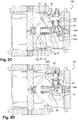
- FIG. 2A shows a cross-sectional view of a DES 10 revealing part of the components of the actuating mechanism 20.
- the actuating mechanism 20 is a single actuating mechanism 20 for operating both pistons 30, 40, and comprises a crankshaft 28 extending along and rotatable about a crank axis, the crankshaft 28 comprising two main journals 21, 27 extending along the crank axis, two main webs 22, 26 extending from the main journals 21, 27, and two crankpins 23A, 24A provided between the main webs 22, 26.
- the crankpins 23A, 24A extend along axes parallel to the crank axis, but the axis of one crankpin 23A, 24A has a phase offset to the other relative to the crank axis.
- crankpins 23A, 24A are provided in a split-crankpin arrangement, interconnected by a crankpin web 25 extending therebetween, also forming part of the crankshaft 28.
- the crankshaft components do not move relative to each other.
- the actuating mechanism also comprises piston rods 23, 24 rotatably mounted on each crankpin 23A, 24A connecting the crankshaft 28 to the pistons 30, 40.
- one main journal 21, one main web 22, the disconnector piston rod 23 (and the position of the disconnector crankpin 23A) are components of the actuating mechanism which can be seen.
- the crankpin web 25 interconnecting the crankpins 23A, 24A is also visible.
- Figure 2C however provides a view from the reverse side of the same cross-section as in figure 2A , and here the other main journal 27, the other main web 26, the earthing piston rod 24 (and the position of the earthing crankpin 24A) are components of the actuating mechanism 20 for the earthing piston 40 which can be seen, but not entirely those of the disconnector piston 30.
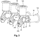
- the actuating mechanism 20 of the DES 10 can also be seen in Figure 3 .
- the crankshaft 28 which may be provided as an assembly of multiple parts or as a single unit, is mounted to the housing 11 of the DES 10 so as to be rotatable about the crank axis.
- the crank axis extends perpendicularly to a plane parallel to both axes of the piston 30, 40, and therefore, in this case, to the plane in which the axes of both the disconnector piston 30 and the earthing piston 40 lie.
- the crank axis intersects the axes of both pistons 30, 40, and therefore, in this case, goes through the intersection of the axes of the two pistons 30, 40.
- the crank axis is located behind the back end of both pistons 30, 40 when they are in the retracted position.
- the actuating mechanism 20 is arranged such that rotation of the crankshaft 28 can place the pistons 30, 40 in three distinct configurations.
- both the disconnector piston 30 and the earthing piston 40 are in the retracted position; shown in figures 2A and 2C (view from the reverse side).
- the disconnector piston 30 is in the extended position while the earthing piston 40 is in the retracted position; this is shown in figure 2B , which provides the view from the same side as figure 2A .
- the disconnector piston 30 is in the retracted position while the earthing piston 40 is in the extended position; this is shown in figure 2D which provides a view from the same side as figure 2C .
- each piston When in the configuration where both pistons are in the retracted position, each piston is not connected to its electrical contact socket 32, 42 and is flush with the housing 11. In particular, each piston 30, 40 is flush with the cylinder openings 13A, 14A where the piston 30, 40 can extend from.
- This retracted position is the same position that a piston 30, 40 will be in when in the configurations where the other piston 40, 30 is in the extended position.
- the GIS 100 is arranged such that the pistons of the DES 10 connect to, completely or as designed, the electrical contact socket 32, 42 when a piston 30, 40 is in the extended position.
- the description will commence with the configuration where both pistons 30, 40 are retracted.
- the disconnector piston 30 and the earthing piston 40 are both flush with the DES housing 11.
- the crankshaft 28 When the crankshaft 28 is rotated anticlockwise about the crank axis (w.r.t. figure 2A ), it pushes on the disconnector piston rod 23 which in turn causes translation of the disconnector piston 30 within its cylinder 13, causing it to extend out of the cylinder opening 13A towards its disconnector contact socket 32.
- Figure 2B shows the disconnector piston 30 in the extended position, where it engages the disconnector contact socket 32 and thereby places the electrical conductor 55 of the GIS in electrical contact with the busbar 35 or a cable end.
- the DES 10 is most often in this position during normal operations, where it allows the flow of electricity across the relevant section of the GIS 100.
- crankshaft 28 has made a rotation of 120°. While the disconnector piston 30 has been displaced from its retracted position to its extended position, it has done so with the disconnector piston rod 23 remaining on the same side of the crank axis (the disconnector crankpin 23A remaining on the same side of the axis of the disconnector piston 30); see figures 2A and 2B . Meanwhile, the earthing piston rod 24 has cut across the crank axis (the earthing crankpin 24A now being on the other side of the axis of the earthing piston 40); see figures 2C and 2B to visualise.
- the angle of the main webs 22, 26 relative to the crank axis are not necessarily the same, and correspond to the phase offset of the crankpins 23A, 24A.
- the earthing crankpin 24A linked to the earthing piston rod 24 has moved around the crank axis to an opposite corresponding side of crank axis with respect to the earthing piston axis. Consequently, the earthing piston 40 which was initially flush with the housing 11 with the disconnector piston 30 in the retracted position, is again flush with the housing 11 with the disconnector piston 30 in the extended position. In between, the earthing piston 40 has dipped behind the cylinder opening 14A.
- the disconnector piston 30 Before the DES 10 can be earthed, the disconnector piston 30 must at first be disconnected from the disconnector contact socket 32 for safety reasons. So as to disconnect the disconnector piston 30, the crankshaft 28 is rotated clockwise 120° about the crank axis (w.r.t. figures 2A and 2B ). This retracts the disconnector piston 30 until it is in the retracted position flush with the housing 11, and with the earthing piston 40 also being in the retracted position, the earthing crankpin 24A having moved back to the initial position shown in figure 2A . In this configuration, both the disconnector piston 30 and the earthing piston 40 are again in the retracted position flush with the DES housing 11.
- crankshaft 20 has made a rotation of a further 120°. While the earthing piston 40 has been displaced from its retracted position to its extended position, it has done so with the earthing piston rod 24 remaining on the same side of the crank axis (the earthing crankpin 24A remaining on the same side of the axis of the earthing piston 40); see figures 2C and 2D . This time however, the disconnector piston rod 23 has cut across the crank axis (the disconnector crankpin 23A now being on the other side of the axis of the disconnector piston 30); see figures 2D and 2A to visualise.
- the disconnector crankpin 23A linked to the disconnector piston rod 23 has moved around the crank axis to an opposite corresponding side of crank axis with respect to the disconnector piston axis. Consequently, the disconnector piston 30 which was initially flush with the housing 11 with the earthing piston 40 in the retracted position, is again flush with the housing 11 with the earthing piston 40 in the extended position. In between, the disconnector piston 30 has dipped behind the cylinder opening 13A.
- crankshaft 28 In order to place the disconnector piston 30 back in contact with the disconnector contact socket 32, the crankshaft 28 needs to be rotated back in the clockwise direction (anticlockwise in the view shown in figure 2A and 2B ). It should also be noted that the DES 10 is arranged such that continuous rotation of the crankshaft 28 is mechanically blocked in both directions, preventing the disconnector piston 30 and the earthing piston 40 from being extended out from the housing 11, or being in the extended position, at the same time.
- crankpins 23A, 24A being provided with a phase offset to each other relative to the crank axis in this embodiment permits each piston 30, 40 to be in their extended position with their piston rod 23, 24 parallel to the piston axis (maximum reach), while the crankpin 24A, 23A of the other piston is located such that the other piston 40, 30 is in the retracted position.
- the GIS 100 such that the pistons 30, 40 of the DES 10 are flush with the housing 11 when in their retracted position and to position the DES or electrical contact sockets 32, 42 so that the pistons 30, 40 are connected to their electrical contact sockets 32, 42, completely or as designed, when in their extended position.
- FIG. 1 shows the three-phase GIS 100
- three separate DES 10 are arranged side-by-side in the same orientation, each one intended for disconnecting and earthing one of the three electrical conductors 55 in the GIS 100.
- Each DES 10 functions as previously described, however the crankshafts 28 of the three DES 10 are connected to each other forming a common crankshaft 28 and the three DES 10 can be operated synchronously.
- Figure 3 provides a perspective view of the three DES 10 with the housing 11 of each DES 10 mostly stripped away, showing the actuating mechanisms 20 linked by a common crankshaft 28.
- the common crankshaft 28 will be arranged such that it does not conduct electricity between the three electrical conductors 55, and again may be provided as an assembly of multiple parts, or as a single unit.
- the pistons 30, 40 of all three DES 10 and their actuating mechanisms 20 may be provided in a common housing.
- the invention is also applicable to single-phase GIS where just one DES 10 needs to be provided at relevant sections of the GIS. It will also be appreciated that existing GIS can readily be retrofitted so as to provide a GIS 100 according to the present invention.
- the GIS 100 of the present invention thus allows the disconnector piston 30 and earthing piston 40 to be operated while causing less dielectric stress.
- the provision of the crankshaft 28 neatly enables the pistons 30, 40 to be in the retracted position while the other is in the extended position or the retracted position.
- crankshaft 28, unlike a straight rotary shaft, does not run along the crank axis for its entire length means that it frees up space along and around the crank axis. This crucially allows the crankpin 23A, 24A and piston rod 23, 24 to occupy corresponding positions on both sides of the crank axis, enabling the piston 30, 40 to be flush with the housing 11 in the retracted position.
- the crankshaft 28 By having one piston 30, 40 in the retracted position flush with the housing 11 while the other is in the extended position, the dielectric stress at the openings 13A, 14A of the housing 11 is significantly reduced.
- the pistons 30, 40 being arranged not to extend from housing 11 while the other 40, 30 is moving between the retracted position and the extended position also contributes to this.
- the crankshaft 28 being located in the DES 10 with the crank axis extending perpendicularly from a plane parallel to the two piston axes, and intersecting the two piston axes, allows for a compact construction.
- a reduction in part-count of the DES may also be realised.
- crankpins in the description above are provided on different axis, they may alternatively be provided on the same axis.
- the pistons are angled at 90° to one another, they may alternatively be provided at a different angle to each other, e.g. between 60° and 150°.
- the pistons are at provided with their axes angled at 120° to each other, both pistons are connected to the crankshaft on crankpins located on the same axis (no phase offset).
Landscapes
- Gas-Insulated Switchgears (AREA)
Abstract
Description
- The invention relates to the field of gas-insulated switchgears (GIS). More particularly, the invention relates to a GIS having a disconnector-earthing switch (DES) which causes less dielectric field stress when disconnecting and earthing the electrical conductor in the GIS.
- Switchgears are provided in high-voltage electrical power systems to enable downstream equipment to be de-energised and isolated so as to permit, for example, repair, maintenance, or installation of a new component. Gas-insulated switchgears (GIS) are generally preferred to other types of switchgears as they are capable of safely handling large currents and power levels while occupying a substantially smaller volume. Electrical conductors in the GIS are fitted inside tubular compartments filled with insulating gas, typically SF6 gas.
- When work has to be conducted on the GIS, e.g. maintenance, or to facilitate testing of the GIS (e.g. dielectric testing), the power supply has to be switched off, typically with the circuit breakers being disconnected. However, an induced current or a residual charge may sometimes exist in the electrical conductors of the GIS even after the power supply has been switched off, which poses a risk of electrocution for service personnel accessing the interior of the GIS if it is not discharged beforehand. Therefore, once the circuit breakers in a GIS have been operated, disconnector-earthing switches (DES) must then be operated to disconnect and isolate the relevant section of the GIS from the busbar or cable end, and to subsequently earth it by putting it in contact with the GIS enclosure (e.g. the tubular compartments), itself connected to earth.
- The DES typically comprises a disconnector piston arranged to connect to and disconnect from a disconnector contact socket provided in the GIS, and an earthing piston arranged to connect to and disconnect from an earthing contact socket provided in the GIS. Before the earthing piston of the DES can be connected to the earthing contact socket, the disconnector piston must first be disconnected. For safety reasons, it is imperative that disconnector piston and the earthing piston are never both connected to their electrical contact sockets at the same time. As such, a single actuating mechanism is often employed for operating both pistons of the DES, mechanically configured such that one piston is always disconnected from its electrical contact socket prior to the other being connected to its electrical contact socket.
-
US2010/0089875 A1 discloses such a DES in a three-phase GIS. Infigure 1 of this prior art document, a DES is shown comprising disconnector piston and an earthing piston mechanically connected to an actuating mechanism. The actuating mechanism comprises a rotary control shaft connected to levers to operate the pistons such that when one is extended to connect to the respective electrical contact socket, the other retracts such that the pistons do not connect to their electrical contact sockets simultaneously. However, when one piston is in the process of extending or retracting, the other is in the process of retracting or extending, which could potentially cause arcing due to the proximity of both pistons to their respective electrical contacts midway during the movement. Furthermore, when one piston is in the extended position in contact with the electrical contact socket, the other is in a retracted position where it is not flush with the opening in the DES housing, i.e. the cylinder opening of the cylinder within which the piston is provided. This can cause an undesirable dielectric stress at the opening in the housing. - In
figure 2 of the same document, a DES is disclosed where the disconnector piston and the earthing piston are also mechanically connected, for operation by a different actuating mechanism. The actuating mechanism comprises a profiled actuation member which is rotated to guide cam followers connected to levers so as to extend and retract the pistons. Furthermore, it is arranged such that when either one of the piston is being extended or retracted, the other piston remains in a retracted position flush with the DES housing. While this reduces dielectric stress significantly, the actuating mechanism is not particularly small, taking up quite a bit of space adjacent the two pistons, which again may cause dielectric stress. Moreover, the actuating mechanism does not have a low part-count. - As such, there is clearly a need for a GIS with a DES having improved dielectric behaviour. There is equally a need for a GIS with a DES which occupies less space, and preferably with a lower part-count.
- The present invention provides a gas-insulated switchgear (GIS) comprising a disconnector-earthing switch (DES), the DES comprising a housing, a disconnector piston and an earthing piston, both pistons arranged in the housing and being each extendable and retractable thereto along a respective axis, the axes of the pistons being at an angle to each other but parallel to a plane, the DES further comprising an actuating mechanism arranged to operate the pistons to place them in three configurations, namely where both the disconnector piston and earthing piston are in the retracted position, where the disconnector piston is in the extended position and the earthing piston is in the retracted position, and where the earthing piston is in the extended position and the disconnector piston is in the retracted position, the actuating mechanism comprising a crankshaft and two piston rods, each piston rod linking a respective piston to the crankshaft, the crankshaft being arranged to rotate about a crank axis perpendicular to the plane parallel to the axes of the pistons and which intersects the axes of the two pistons, the DES arranged such that whenever a piston is in the retracted position it is flush with the housing.
- Preferable features of the invention are detailed in the appendant claims.
- The invention will be better understood when reading the following detailed description and non-limiting examples, as well as studying the figures, wherein:
-
Figure 1 shows a cross-section view of a GIS according to a preferred embodiment of the present invention, with a perspective view of two DES, each with the disconnector piston and the earthing piston in the retracted position, -
Figure 2A show a cross-section view of the DES infigure 1 , -
Figure 2B show a cross-section view of the DES infigure 1 with the disconnector piston extended and the earthing piston retracted, -
Figure 2C show a cross-section view of the DES infigure 1 from the reverse side with both pistons in the retracted position, -
Figure 2D show a cross-section view of the DES infigure 1 from the reverse side with the earthing piston extended and the disconnector piston retracted, and -
Figure 3 shows a perspective view of the GIS infigure 1 , showing each DES with the housing mostly removed and its actuating mechanism linked by a common crankshaft. - In all of these figures, identical references can designate identical or similar elements. In addition, the various portions shown in the figures are not necessarily shown according to a uniform scale, in order to make the figures more legible.
-
Figure 1 shows a partial cross-section view of a section of a three-phase GIS 100 according to a preferred embodiment of the invention. TheDES 10 are positioned adjacent to each other and oriented in the same sense (only two of the threeDES 10 being visible due to the position of the cross-section). As theDES 10 are identical, only one will be described. - The DES 10 comprises a
housing 11 within which adisconnector piston 30 and anearthing piston 40 are provided, arranged for movement along axes which are at an angle of 90° to one another, but lying in the same plane. Thedisconnector piston 30 is oriented to move along a horizontal axis to extend from and retract into thehousing 11, while theearthing piston 40 is oriented to move along a vertical axis to extend from and retract into thehousing 11. To guide movement of thepistons housing 11 is provided withcylinders cylinder piston housing 11. Thecylinder openings housing 11 from which thepistons Electrical contact sockets GIS 100 for thepistons disconnector contact socket 32 on the right of thedisconnector piston 30 is linked to abusbar 35 or a cable end, while theearthing contact socket 42 vertically above theearthing piston 40 is linked to theGIS enclosure 45. TheDES 10 is connected on the left to anelectrical conductor 55 extending through a respective section of the tubular compartment in theGIS 100. It will be appreciated that other orientations of theDES 10 are also possible. - The
DES 10 is shown in the configuration where both the disconnector andearthing pistons housing 11, in particular with thecylinder openings cylinders piston housing 11 from which it can extend, which in this embodiment is the front end of the cylinder opening 13A, 14A. Ideally, the front end of thepiston piston - The
DES 10 further comprises anactuating mechanism 20 within thehousing 11 comprising acrankshaft 28 andpiston rods pistons main journal 21 of thecrankshaft 28 can be seen protruding out of thehousing 11. When thecrankshaft 28 is rotated, e.g. by an actuating device (not shown), such as a motor or hand-crank, the rotary motion is converted to linear motion of thepistons electrical contact sockets housing 11 and thepistons electrical conductor 55 of theGIS 100 can be disconnected and earthed by operating theactuating mechanism 20. So as to provide a better understanding of theactuating mechanism 20, it will be discussed in further detail below with reference to figures providing cross-section views of theDES 10. -
Figure 2A shows a cross-sectional view of aDES 10 revealing part of the components of theactuating mechanism 20. Theactuating mechanism 20 is asingle actuating mechanism 20 for operating bothpistons crankshaft 28 extending along and rotatable about a crank axis, thecrankshaft 28 comprising twomain journals main webs main journals crankpins main webs crankpins crankpin crankpins crankpins crankpin web 25 extending therebetween, also forming part of thecrankshaft 28. The crankshaft components do not move relative to each other. The actuating mechanism also comprisespiston rods crankpin crankshaft 28 to thepistons - In this figure, one
main journal 21, onemain web 22, the disconnector piston rod 23 (and the position of thedisconnector crankpin 23A) are components of the actuating mechanism which can be seen. Thecrankpin web 25 interconnecting thecrankpins crankpin web 25, only the details of theactuating mechanism 20 for thedisconnector piston 30 are visible in this figure while those of the earthingpiston 40 are not entirely visible.Figure 2C however provides a view from the reverse side of the same cross-section as infigure 2A , and here the othermain journal 27, the othermain web 26, the earthing piston rod 24 (and the position of the earthingcrankpin 24A) are components of theactuating mechanism 20 for the earthingpiston 40 which can be seen, but not entirely those of thedisconnector piston 30. Theactuating mechanism 20 of theDES 10 can also be seen inFigure 3 . - The
crankshaft 28, which may be provided as an assembly of multiple parts or as a single unit, is mounted to thehousing 11 of theDES 10 so as to be rotatable about the crank axis. The crank axis extends perpendicularly to a plane parallel to both axes of thepiston disconnector piston 30 and the earthingpiston 40 lie. In fact, the crank axis intersects the axes of bothpistons pistons pistons - The
actuating mechanism 20 is arranged such that rotation of thecrankshaft 28 can place thepistons disconnector piston 30 and the earthingpiston 40 are in the retracted position; shown infigures 2A and2C (view from the reverse side). In another configuration, thedisconnector piston 30 is in the extended position while the earthingpiston 40 is in the retracted position; this is shown infigure 2B , which provides the view from the same side asfigure 2A . In a yet another configuration, thedisconnector piston 30 is in the retracted position while the earthingpiston 40 is in the extended position; this is shown infigure 2D which provides a view from the same side asfigure 2C . - When in the configuration where both pistons are in the retracted position, each piston is not connected to its
electrical contact socket housing 11. In particular, eachpiston cylinder openings piston piston other piston GIS 100 is arranged such that the pistons of theDES 10 connect to, completely or as designed, theelectrical contact socket piston actuating mechanism 20 operates and moves thepistons pistons - In
figures 1 and2A , thedisconnector piston 30 and the earthingpiston 40 are both flush with theDES housing 11. When thecrankshaft 28 is rotated anticlockwise about the crank axis (w.r.t.figure 2A ), it pushes on thedisconnector piston rod 23 which in turn causes translation of thedisconnector piston 30 within itscylinder 13, causing it to extend out of the cylinder opening 13A towards itsdisconnector contact socket 32.Figure 2B shows thedisconnector piston 30 in the extended position, where it engages thedisconnector contact socket 32 and thereby places theelectrical conductor 55 of the GIS in electrical contact with thebusbar 35 or a cable end. TheDES 10 is most often in this position during normal operations, where it allows the flow of electricity across the relevant section of theGIS 100. - At the same time, it will be observed that the
crankshaft 28 has made a rotation of 120°. While thedisconnector piston 30 has been displaced from its retracted position to its extended position, it has done so with thedisconnector piston rod 23 remaining on the same side of the crank axis (thedisconnector crankpin 23A remaining on the same side of the axis of the disconnector piston 30); seefigures 2A and 2B . Meanwhile, the earthingpiston rod 24 has cut across the crank axis (the earthingcrankpin 24A now being on the other side of the axis of the earthing piston 40); seefigures 2C and2B to visualise. Note that the angle of themain webs crankpins crankpin 24A linked to the earthingpiston rod 24 has moved around the crank axis to an opposite corresponding side of crank axis with respect to the earthing piston axis. Consequently, the earthingpiston 40 which was initially flush with thehousing 11 with thedisconnector piston 30 in the retracted position, is again flush with thehousing 11 with thedisconnector piston 30 in the extended position. In between, the earthingpiston 40 has dipped behind thecylinder opening 14A. - Before the
DES 10 can be earthed, thedisconnector piston 30 must at first be disconnected from thedisconnector contact socket 32 for safety reasons. So as to disconnect thedisconnector piston 30, thecrankshaft 28 is rotated clockwise 120° about the crank axis (w.r.t.figures 2A and 2B ). This retracts thedisconnector piston 30 until it is in the retracted position flush with thehousing 11, and with the earthingpiston 40 also being in the retracted position, the earthingcrankpin 24A having moved back to the initial position shown infigure 2A . In this configuration, both thedisconnector piston 30 and the earthingpiston 40 are again in the retracted position flush with theDES housing 11. - In order to describe the extension of the earthing
piston 40, theactuating mechanism 20 will be now be described primarily with reference toFigures 2C and 2D . When thecrankshaft 28 is rotated in the anticlockwise direction (further clockwise in the views shown infigures 2A and 2B ), it pushes on the earthingpiston rod 24 which in turn causes translation of the earthingpiston 40 within its cylinder, causing it to extend out of the cylinder opening 14A towards its earthingcontact socket 42.Figure 2D shows the earthingpiston 40 in the extended position, where it engages the earthingcontact socket 42 and thereby places theelectrical conductor 55 of the GIS in electrical contact with theGIS enclosure 45 which is earthed. This allows electric charge in the relevant section of theGIS 100 to be discharged. - It will be observed that the
crankshaft 20 has made a rotation of a further 120°. While the earthingpiston 40 has been displaced from its retracted position to its extended position, it has done so with the earthingpiston rod 24 remaining on the same side of the crank axis (the earthingcrankpin 24A remaining on the same side of the axis of the earthing piston 40); seefigures 2C and 2D . This time however, thedisconnector piston rod 23 has cut across the crank axis (thedisconnector crankpin 23A now being on the other side of the axis of the disconnector piston 30); seefigures 2D and2A to visualise. Thedisconnector crankpin 23A linked to thedisconnector piston rod 23 has moved around the crank axis to an opposite corresponding side of crank axis with respect to the disconnector piston axis. Consequently, thedisconnector piston 30 which was initially flush with thehousing 11 with the earthingpiston 40 in the retracted position, is again flush with thehousing 11 with the earthingpiston 40 in the extended position. In between, thedisconnector piston 30 has dipped behind thecylinder opening 13A. - In order to place the
disconnector piston 30 back in contact with thedisconnector contact socket 32, thecrankshaft 28 needs to be rotated back in the clockwise direction (anticlockwise in the view shown infigure 2A and 2B ). It should also be noted that theDES 10 is arranged such that continuous rotation of thecrankshaft 28 is mechanically blocked in both directions, preventing thedisconnector piston 30 and the earthingpiston 40 from being extended out from thehousing 11, or being in the extended position, at the same time. In addition, thecrankpins piston piston rod crankpin other piston - It will be appreciated that several aspects play a role in ensuring the
pistons actuating mechanism 20, are flush with thehousing 11 in the retracted position and engage theelectrical contact sockets pistons piston rods electrical contact socket crankpins housing 11, etc., may all play a role. It will be within the abilities of the skilled person to arrange theGIS 100 such that thepistons DES 10 are flush with thehousing 11 when in their retracted position and to position the DES orelectrical contact sockets pistons electrical contact sockets - Returning to
figure 1 showing the three-phase GIS 100, it should be noted that threeseparate DES 10 are arranged side-by-side in the same orientation, each one intended for disconnecting and earthing one of the threeelectrical conductors 55 in theGIS 100. EachDES 10 functions as previously described, however thecrankshafts 28 of the threeDES 10 are connected to each other forming acommon crankshaft 28 and the threeDES 10 can be operated synchronously.Figure 3 provides a perspective view of the threeDES 10 with thehousing 11 of eachDES 10 mostly stripped away, showing theactuating mechanisms 20 linked by acommon crankshaft 28. Thecommon crankshaft 28 will be arranged such that it does not conduct electricity between the threeelectrical conductors 55, and again may be provided as an assembly of multiple parts, or as a single unit. Depending on the arrangement of theGIS 100 andDES 10, it may also be possible for thepistons DES 10 and theiractuating mechanisms 20 to be provided in a common housing. Needless to say, the invention is also applicable to single-phase GIS where just oneDES 10 needs to be provided at relevant sections of the GIS. It will also be appreciated that existing GIS can readily be retrofitted so as to provide aGIS 100 according to the present invention. - The
GIS 100 of the present invention thus allows thedisconnector piston 30 and earthingpiston 40 to be operated while causing less dielectric stress. The provision of thecrankshaft 28 neatly enables thepistons crankshaft 28, unlike a straight rotary shaft, does not run along the crank axis for its entire length means that it frees up space along and around the crank axis. This crucially allows thecrankpin piston rod piston housing 11 in the retracted position. By having onepiston housing 11 while the other is in the extended position, the dielectric stress at theopenings housing 11 is significantly reduced. Thepistons housing 11 while the other 40, 30 is moving between the retracted position and the extended position also contributes to this. On top of that, thecrankshaft 28 being located in theDES 10 with the crank axis extending perpendicularly from a plane parallel to the two piston axes, and intersecting the two piston axes, allows for a compact construction. Finally, by providing thecrankshaft 28 as a single unit, a reduction in part-count of the DES may also be realised. - It should be understood that variations to the preferred embodiment above are possible. For example, while the crankpins in the description above are provided on different axis, they may alternatively be provided on the same axis. Equally, while the pistons are angled at 90° to one another, they may alternatively be provided at a different angle to each other, e.g. between 60° and 150°. In one variant of the present embodiment, the pistons are at provided with their axes angled at 120° to each other, both pistons are connected to the crankshaft on crankpins located on the same axis (no phase offset). Starting with both pistons in the retracted position flush with the housing, when the crankshaft is rotated 120°, one piston will be in the extended position while the other will be in the retracted position. When the crankshaft is rotated 120° in the opposite direction, each piston will be again in the retracted position. And when rotated a further 120°, the other piston will extend with to the extended position, while the first will be in the retracted position.
- While the actuating mechanism is said to be able to place the pistons in three configurations, this does not necessarily restrict the actuating mechanism from placing the pistons in yet other configurations.
Claims (10)
- A gas-insulated switchgear (GIS) (100) comprising a disconnector-earthing switch (DES), the DES (10) comprising a housing (11), a disconnector piston (30) and an earthing piston (40), both pistons arranged in the housing (11) and being each extendable and retractable thereto along a respective axis, the axes of the pistons (30, 40) being at an angle to each other but parallel to a plane, the DES (10) further comprising an actuating mechanism (20) arranged to operate the pistons (30, 40) to place them in three configurations, namely where both the disconnector piston (30) and earthing piston (40) are in the retracted position, where the disconnector piston (30) is in the extended position and the earthing piston (40) is in the retracted position, and where the earthing piston (40) is in the extended position and the disconnector piston (30) is in the retracted position,
characterised in that the actuating mechanism (20) comprises a crankshaft (28) and two piston rods (23, 24), each piston rod (23, 24) linking a respective piston (30, 40) to the crankshaft (28), the crankshaft (28) being arranged to rotate about a crank axis perpendicular to the plane parallel to the axes of the pistons (30, 40) and which intersects the axes of the two pistons (30, 40), and further in that whenever a piston (30, 40) is in the retracted position it is flush with the housing (11). - A GIS according to claim 1, characterised in that the piston (30, 40) is flush with the housing (11) in that the front end of the piston (30, 40) is in the same plane as the front end of a cylinder opening (13, 14) provided in the housing (11) from which the piston (30, 40) extends.
- A GIS according to claim 1 or 2, characterised in that the axes of the pistons (30, 40) are at an angle of between 60° and 150° to each other.
- A GIS according to claim 3, characterised in that the axes of the pistons (30, 40) are at an angle of 90° to each other.
- A GIS according to any preceding claim, characterised in that the piston rods (13, 14) are connected to the crankshaft (28) at crankpins (23A, 24A) located on different axes.
- A GIS according to claim 5, characterised in that the crankpins (23A, 24A) are provided on axes with a 30° phase offset relative to each other with respect to the crank axis.
- A GIS according to any preceding claim, characterised in that the piston rods (23, 24) are connected to the crankshaft (28) at crankpins (23A, 24A) on the same axis.
- A GIS according to any preceding claim characterised in that when one piston (30, 40) is moved from the extended position to the retracted position, the piston rod (24, 23) of the other piston (40, 30) cuts across the crank axis.
- A GIS according to any preceding claim characterised in that a piston (30, 40) is in its retracted position when the respective crankpin (23A, 24A) is on one side of the crank axis relative to the piston axis and also when it is at an opposite corresponding side of the crank axis relative to the piston axis.
- A GIS according to any preceding claim characterised in that three DES (10) are provided adjacent to each other and arranged in the same orientation, the crankshafts (28) of the three DES (10) being connected to form a common crankshaft (28).
Priority Applications (2)
| Application Number | Priority Date | Filing Date | Title |
|---|---|---|---|
| EP16204156.0A EP3336870B1 (en) | 2016-12-14 | 2016-12-14 | A gis with a disconnector-earthing switch |
| PCT/EP2017/082583 WO2018108990A1 (en) | 2016-12-14 | 2017-12-13 | A gis with a disconnector-earthing switch |
Applications Claiming Priority (1)
| Application Number | Priority Date | Filing Date | Title |
|---|---|---|---|
| EP16204156.0A EP3336870B1 (en) | 2016-12-14 | 2016-12-14 | A gis with a disconnector-earthing switch |
Publications (2)
| Publication Number | Publication Date |
|---|---|
| EP3336870A1 true EP3336870A1 (en) | 2018-06-20 |
| EP3336870B1 EP3336870B1 (en) | 2021-11-03 |
Family
ID=57570153
Family Applications (1)
| Application Number | Title | Priority Date | Filing Date |
|---|---|---|---|
| EP16204156.0A Active EP3336870B1 (en) | 2016-12-14 | 2016-12-14 | A gis with a disconnector-earthing switch |
Country Status (2)
| Country | Link |
|---|---|
| EP (1) | EP3336870B1 (en) |
| WO (1) | WO2018108990A1 (en) |
Cited By (4)
| Publication number | Priority date | Publication date | Assignee | Title |
|---|---|---|---|---|
| CN110428996A (en) * | 2019-06-18 | 2019-11-08 | 河南平高电气股份有限公司 | Quick earthing switch and GIS equipment |
| CN110428995A (en) * | 2019-06-18 | 2019-11-08 | 河南平高电气股份有限公司 | GIS equipment and its quick earthing switch |
| EP4280243A1 (en) * | 2022-05-20 | 2023-11-22 | Abb Schweiz Ag | Medium voltage switchgear disconnector system |
| US12456589B2 (en) | 2020-05-19 | 2025-10-28 | Hitachi Energy Ltd | Apparatus for operating an electric switching device |
Families Citing this family (1)
| Publication number | Priority date | Publication date | Assignee | Title |
|---|---|---|---|---|
| EP3836182B1 (en) * | 2019-12-11 | 2023-03-08 | ABB Schweiz AG | A three-position disconnector switch |
Citations (5)
| Publication number | Priority date | Publication date | Assignee | Title |
|---|---|---|---|---|
| US5796060A (en) * | 1995-03-28 | 1998-08-18 | Asea Brown Boveri Ag | Gas insulated switchgear with grounding and disconnecting switches |
| US20100089875A1 (en) | 2008-10-14 | 2010-04-15 | Areva T&D Ag | High and medium voltage switch apparatus with two interrupters, having common means for actuating the movable contacts of the interrupters |
| US20120118709A1 (en) * | 2009-06-23 | 2012-05-17 | Siemens Aktiengesellschaft | High-voltage assembly |
| US20140116859A1 (en) * | 2011-06-28 | 2014-05-01 | Hyundai Heavy Industries Co., Ltd. | 3-way switch for a gas-insulated apparatus |
| EP2824686A1 (en) * | 2013-07-10 | 2015-01-14 | Siemens Aktiengesellschaft | High-voltage electric switching arrangement in a metal casing |
-
2016
- 2016-12-14 EP EP16204156.0A patent/EP3336870B1/en active Active
-
2017
- 2017-12-13 WO PCT/EP2017/082583 patent/WO2018108990A1/en not_active Ceased
Patent Citations (5)
| Publication number | Priority date | Publication date | Assignee | Title |
|---|---|---|---|---|
| US5796060A (en) * | 1995-03-28 | 1998-08-18 | Asea Brown Boveri Ag | Gas insulated switchgear with grounding and disconnecting switches |
| US20100089875A1 (en) | 2008-10-14 | 2010-04-15 | Areva T&D Ag | High and medium voltage switch apparatus with two interrupters, having common means for actuating the movable contacts of the interrupters |
| US20120118709A1 (en) * | 2009-06-23 | 2012-05-17 | Siemens Aktiengesellschaft | High-voltage assembly |
| US20140116859A1 (en) * | 2011-06-28 | 2014-05-01 | Hyundai Heavy Industries Co., Ltd. | 3-way switch for a gas-insulated apparatus |
| EP2824686A1 (en) * | 2013-07-10 | 2015-01-14 | Siemens Aktiengesellschaft | High-voltage electric switching arrangement in a metal casing |
Cited By (6)
| Publication number | Priority date | Publication date | Assignee | Title |
|---|---|---|---|---|
| CN110428996A (en) * | 2019-06-18 | 2019-11-08 | 河南平高电气股份有限公司 | Quick earthing switch and GIS equipment |
| CN110428995A (en) * | 2019-06-18 | 2019-11-08 | 河南平高电气股份有限公司 | GIS equipment and its quick earthing switch |
| CN110428996B (en) * | 2019-06-18 | 2021-02-23 | 河南平高电气股份有限公司 | Quick earthing switch and GIS equipment |
| US12456589B2 (en) | 2020-05-19 | 2025-10-28 | Hitachi Energy Ltd | Apparatus for operating an electric switching device |
| EP4280243A1 (en) * | 2022-05-20 | 2023-11-22 | Abb Schweiz Ag | Medium voltage switchgear disconnector system |
| US12444912B2 (en) | 2022-05-20 | 2025-10-14 | Abb Schweiz Ag | Medium voltage switchgear disconnector system |
Also Published As
| Publication number | Publication date |
|---|---|
| WO2018108990A1 (en) | 2018-06-21 |
| EP3336870B1 (en) | 2021-11-03 |
Similar Documents
| Publication | Publication Date | Title |
|---|---|---|
| EP3336870B1 (en) | A gis with a disconnector-earthing switch | |
| AU2011223278B2 (en) | A switch arrangement for an electrical switchgear | |
| KR101605134B1 (en) | Disconnecting switch and earthing switch for gas insulated switchgear | |
| US3801768A (en) | Grounding switch | |
| EP2405546B1 (en) | Electrical switchgear | |
| EP3836182B1 (en) | A three-position disconnector switch | |
| US10673212B2 (en) | Switchgear | |
| HU189964B (en) | Metal-clad gas-insulation switching apparatus | |
| EP2180490A1 (en) | A switching device, a switchgear provided therewith, and a method of operating a switching device | |
| US10763062B2 (en) | Switching device with dual conductive housing | |
| WO2011020507A1 (en) | Breaker module for medium-voltage switchgear and medium-voltage switchgear | |
| KR200486467Y1 (en) | Gas insulated high voltage switchgear | |
| JP6623622B2 (en) | Gas insulated switchgear | |
| KR101469308B1 (en) | Gas Insulated Switchgear | |
| EP2363930A1 (en) | A switch arrangement for an electrical switchgear | |
| KR101606073B1 (en) | Gas Insulated Swichgear | |
| EP2363931A1 (en) | A terminal for an electrical switchgear | |
| KR20090080961A (en) | Electrical high voltage switching station | |
| EP2363932A1 (en) | A switch arrangement for an electrical switchgear | |
| CN105305288A (en) | Metal armored power distribution apparatus with divided enclosed spaces | |
| KR101286291B1 (en) | Gas-insulated switchgear | |
| WO2011060796A1 (en) | Switchgear assembly comprising a circuit breaker compartment |
Legal Events
| Date | Code | Title | Description |
|---|---|---|---|
| PUAI | Public reference made under article 153(3) epc to a published international application that has entered the european phase |
Free format text: ORIGINAL CODE: 0009012 |
|
| STAA | Information on the status of an ep patent application or granted ep patent |
Free format text: STATUS: THE APPLICATION HAS BEEN PUBLISHED |
|
| AK | Designated contracting states |
Kind code of ref document: A1 Designated state(s): AL AT BE BG CH CY CZ DE DK EE ES FI FR GB GR HR HU IE IS IT LI LT LU LV MC MK MT NL NO PL PT RO RS SE SI SK SM TR |
|
| AX | Request for extension of the european patent |
Extension state: BA ME |
|
| STAA | Information on the status of an ep patent application or granted ep patent |
Free format text: STATUS: REQUEST FOR EXAMINATION WAS MADE |
|
| 17P | Request for examination filed |
Effective date: 20181220 |
|
| RBV | Designated contracting states (corrected) |
Designated state(s): AL AT BE BG CH CY CZ DE DK EE ES FI FR GB GR HR HU IE IS IT LI LT LU LV MC MK MT NL NO PL PT RO RS SE SI SK SM TR |
|
| STAA | Information on the status of an ep patent application or granted ep patent |
Free format text: STATUS: EXAMINATION IS IN PROGRESS |
|
| 17Q | First examination report despatched |
Effective date: 20201012 |
|
| GRAP | Despatch of communication of intention to grant a patent |
Free format text: ORIGINAL CODE: EPIDOSNIGR1 |
|
| STAA | Information on the status of an ep patent application or granted ep patent |
Free format text: STATUS: GRANT OF PATENT IS INTENDED |
|
| INTG | Intention to grant announced |
Effective date: 20210519 |
|
| GRAS | Grant fee paid |
Free format text: ORIGINAL CODE: EPIDOSNIGR3 |
|
| GRAA | (expected) grant |
Free format text: ORIGINAL CODE: 0009210 |
|
| STAA | Information on the status of an ep patent application or granted ep patent |
Free format text: STATUS: THE PATENT HAS BEEN GRANTED |
|
| AK | Designated contracting states |
Kind code of ref document: B1 Designated state(s): AL AT BE BG CH CY CZ DE DK EE ES FI FR GB GR HR HU IE IS IT LI LT LU LV MC MK MT NL NO PL PT RO RS SE SI SK SM TR |
|
| REG | Reference to a national code |
Ref country code: GB Ref legal event code: FG4D |
|
| REG | Reference to a national code |
Ref country code: AT Ref legal event code: REF Ref document number: 1444721 Country of ref document: AT Kind code of ref document: T Effective date: 20211115 Ref country code: CH Ref legal event code: EP |
|
| REG | Reference to a national code |
Ref country code: IE Ref legal event code: FG4D |
|
| REG | Reference to a national code |
Ref country code: DE Ref legal event code: R096 Ref document number: 602016065676 Country of ref document: DE |
|
| REG | Reference to a national code |
Ref country code: SE Ref legal event code: TRGR |
|
| REG | Reference to a national code |
Ref country code: LT Ref legal event code: MG9D |
|
| REG | Reference to a national code |
Ref country code: NL Ref legal event code: MP Effective date: 20211103 |
|
| REG | Reference to a national code |
Ref country code: AT Ref legal event code: MK05 Ref document number: 1444721 Country of ref document: AT Kind code of ref document: T Effective date: 20211103 |
|
| PG25 | Lapsed in a contracting state [announced via postgrant information from national office to epo] |
Ref country code: RS Free format text: LAPSE BECAUSE OF FAILURE TO SUBMIT A TRANSLATION OF THE DESCRIPTION OR TO PAY THE FEE WITHIN THE PRESCRIBED TIME-LIMIT Effective date: 20211103 Ref country code: LT Free format text: LAPSE BECAUSE OF FAILURE TO SUBMIT A TRANSLATION OF THE DESCRIPTION OR TO PAY THE FEE WITHIN THE PRESCRIBED TIME-LIMIT Effective date: 20211103 Ref country code: FI Free format text: LAPSE BECAUSE OF FAILURE TO SUBMIT A TRANSLATION OF THE DESCRIPTION OR TO PAY THE FEE WITHIN THE PRESCRIBED TIME-LIMIT Effective date: 20211103 Ref country code: BG Free format text: LAPSE BECAUSE OF FAILURE TO SUBMIT A TRANSLATION OF THE DESCRIPTION OR TO PAY THE FEE WITHIN THE PRESCRIBED TIME-LIMIT Effective date: 20220203 Ref country code: AT Free format text: LAPSE BECAUSE OF FAILURE TO SUBMIT A TRANSLATION OF THE DESCRIPTION OR TO PAY THE FEE WITHIN THE PRESCRIBED TIME-LIMIT Effective date: 20211103 |
|
| PG25 | Lapsed in a contracting state [announced via postgrant information from national office to epo] |
Ref country code: IS Free format text: LAPSE BECAUSE OF FAILURE TO SUBMIT A TRANSLATION OF THE DESCRIPTION OR TO PAY THE FEE WITHIN THE PRESCRIBED TIME-LIMIT Effective date: 20220303 Ref country code: PT Free format text: LAPSE BECAUSE OF FAILURE TO SUBMIT A TRANSLATION OF THE DESCRIPTION OR TO PAY THE FEE WITHIN THE PRESCRIBED TIME-LIMIT Effective date: 20220303 Ref country code: PL Free format text: LAPSE BECAUSE OF FAILURE TO SUBMIT A TRANSLATION OF THE DESCRIPTION OR TO PAY THE FEE WITHIN THE PRESCRIBED TIME-LIMIT Effective date: 20211103 Ref country code: NO Free format text: LAPSE BECAUSE OF FAILURE TO SUBMIT A TRANSLATION OF THE DESCRIPTION OR TO PAY THE FEE WITHIN THE PRESCRIBED TIME-LIMIT Effective date: 20220203 Ref country code: NL Free format text: LAPSE BECAUSE OF FAILURE TO SUBMIT A TRANSLATION OF THE DESCRIPTION OR TO PAY THE FEE WITHIN THE PRESCRIBED TIME-LIMIT Effective date: 20211103 Ref country code: LV Free format text: LAPSE BECAUSE OF FAILURE TO SUBMIT A TRANSLATION OF THE DESCRIPTION OR TO PAY THE FEE WITHIN THE PRESCRIBED TIME-LIMIT Effective date: 20211103 Ref country code: HR Free format text: LAPSE BECAUSE OF FAILURE TO SUBMIT A TRANSLATION OF THE DESCRIPTION OR TO PAY THE FEE WITHIN THE PRESCRIBED TIME-LIMIT Effective date: 20211103 Ref country code: GR Free format text: LAPSE BECAUSE OF FAILURE TO SUBMIT A TRANSLATION OF THE DESCRIPTION OR TO PAY THE FEE WITHIN THE PRESCRIBED TIME-LIMIT Effective date: 20220204 Ref country code: ES Free format text: LAPSE BECAUSE OF FAILURE TO SUBMIT A TRANSLATION OF THE DESCRIPTION OR TO PAY THE FEE WITHIN THE PRESCRIBED TIME-LIMIT Effective date: 20211103 |
|
| PG25 | Lapsed in a contracting state [announced via postgrant information from national office to epo] |
Ref country code: SM Free format text: LAPSE BECAUSE OF FAILURE TO SUBMIT A TRANSLATION OF THE DESCRIPTION OR TO PAY THE FEE WITHIN THE PRESCRIBED TIME-LIMIT Effective date: 20211103 Ref country code: SK Free format text: LAPSE BECAUSE OF FAILURE TO SUBMIT A TRANSLATION OF THE DESCRIPTION OR TO PAY THE FEE WITHIN THE PRESCRIBED TIME-LIMIT Effective date: 20211103 Ref country code: RO Free format text: LAPSE BECAUSE OF FAILURE TO SUBMIT A TRANSLATION OF THE DESCRIPTION OR TO PAY THE FEE WITHIN THE PRESCRIBED TIME-LIMIT Effective date: 20211103 Ref country code: EE Free format text: LAPSE BECAUSE OF FAILURE TO SUBMIT A TRANSLATION OF THE DESCRIPTION OR TO PAY THE FEE WITHIN THE PRESCRIBED TIME-LIMIT Effective date: 20211103 Ref country code: DK Free format text: LAPSE BECAUSE OF FAILURE TO SUBMIT A TRANSLATION OF THE DESCRIPTION OR TO PAY THE FEE WITHIN THE PRESCRIBED TIME-LIMIT Effective date: 20211103 Ref country code: CZ Free format text: LAPSE BECAUSE OF FAILURE TO SUBMIT A TRANSLATION OF THE DESCRIPTION OR TO PAY THE FEE WITHIN THE PRESCRIBED TIME-LIMIT Effective date: 20211103 |
|
| REG | Reference to a national code |
Ref country code: DE Ref legal event code: R097 Ref document number: 602016065676 Country of ref document: DE |
|
| PG25 | Lapsed in a contracting state [announced via postgrant information from national office to epo] |
Ref country code: MC Free format text: LAPSE BECAUSE OF FAILURE TO SUBMIT A TRANSLATION OF THE DESCRIPTION OR TO PAY THE FEE WITHIN THE PRESCRIBED TIME-LIMIT Effective date: 20211103 |
|
| PLBE | No opposition filed within time limit |
Free format text: ORIGINAL CODE: 0009261 |
|
| STAA | Information on the status of an ep patent application or granted ep patent |
Free format text: STATUS: NO OPPOSITION FILED WITHIN TIME LIMIT |
|
| REG | Reference to a national code |
Ref country code: BE Ref legal event code: MM Effective date: 20211231 |
|
| 26N | No opposition filed |
Effective date: 20220804 |
|
| GBPC | Gb: european patent ceased through non-payment of renewal fee |
Effective date: 20220203 |
|
| PG25 | Lapsed in a contracting state [announced via postgrant information from national office to epo] |
Ref country code: LU Free format text: LAPSE BECAUSE OF NON-PAYMENT OF DUE FEES Effective date: 20211214 Ref country code: IE Free format text: LAPSE BECAUSE OF NON-PAYMENT OF DUE FEES Effective date: 20211214 Ref country code: AL Free format text: LAPSE BECAUSE OF FAILURE TO SUBMIT A TRANSLATION OF THE DESCRIPTION OR TO PAY THE FEE WITHIN THE PRESCRIBED TIME-LIMIT Effective date: 20211103 |
|
| PG25 | Lapsed in a contracting state [announced via postgrant information from national office to epo] |
Ref country code: SI Free format text: LAPSE BECAUSE OF FAILURE TO SUBMIT A TRANSLATION OF THE DESCRIPTION OR TO PAY THE FEE WITHIN THE PRESCRIBED TIME-LIMIT Effective date: 20211103 Ref country code: BE Free format text: LAPSE BECAUSE OF NON-PAYMENT OF DUE FEES Effective date: 20211231 |
|
| PG25 | Lapsed in a contracting state [announced via postgrant information from national office to epo] |
Ref country code: GB Free format text: LAPSE BECAUSE OF NON-PAYMENT OF DUE FEES Effective date: 20220203 |
|
| PG25 | Lapsed in a contracting state [announced via postgrant information from national office to epo] |
Ref country code: HU Free format text: LAPSE BECAUSE OF FAILURE TO SUBMIT A TRANSLATION OF THE DESCRIPTION OR TO PAY THE FEE WITHIN THE PRESCRIBED TIME-LIMIT; INVALID AB INITIO Effective date: 20161214 |
|
| P01 | Opt-out of the competence of the unified patent court (upc) registered |
Effective date: 20230522 |
|
| PG25 | Lapsed in a contracting state [announced via postgrant information from national office to epo] |
Ref country code: CY Free format text: LAPSE BECAUSE OF FAILURE TO SUBMIT A TRANSLATION OF THE DESCRIPTION OR TO PAY THE FEE WITHIN THE PRESCRIBED TIME-LIMIT Effective date: 20211103 |
|
| PG25 | Lapsed in a contracting state [announced via postgrant information from national office to epo] |
Ref country code: MK Free format text: LAPSE BECAUSE OF FAILURE TO SUBMIT A TRANSLATION OF THE DESCRIPTION OR TO PAY THE FEE WITHIN THE PRESCRIBED TIME-LIMIT Effective date: 20211103 |
|
| PG25 | Lapsed in a contracting state [announced via postgrant information from national office to epo] |
Ref country code: TR Free format text: LAPSE BECAUSE OF FAILURE TO SUBMIT A TRANSLATION OF THE DESCRIPTION OR TO PAY THE FEE WITHIN THE PRESCRIBED TIME-LIMIT Effective date: 20211103 |
|
| PG25 | Lapsed in a contracting state [announced via postgrant information from national office to epo] |
Ref country code: MT Free format text: LAPSE BECAUSE OF FAILURE TO SUBMIT A TRANSLATION OF THE DESCRIPTION OR TO PAY THE FEE WITHIN THE PRESCRIBED TIME-LIMIT Effective date: 20211103 |
|
| REG | Reference to a national code |
Ref country code: CH Ref legal event code: U11 Free format text: ST27 STATUS EVENT CODE: U-0-0-U10-U11 (AS PROVIDED BY THE NATIONAL OFFICE) Effective date: 20260101 |
|
| PGFP | Annual fee paid to national office [announced via postgrant information from national office to epo] |
Ref country code: DE Payment date: 20251126 Year of fee payment: 10 |
|
| PGFP | Annual fee paid to national office [announced via postgrant information from national office to epo] |
Ref country code: IT Payment date: 20251119 Year of fee payment: 10 |
|
| PGFP | Annual fee paid to national office [announced via postgrant information from national office to epo] |
Ref country code: FR Payment date: 20251120 Year of fee payment: 10 |
|
| PGFP | Annual fee paid to national office [announced via postgrant information from national office to epo] |
Ref country code: SE Payment date: 20251119 Year of fee payment: 10 |
|
| PGFP | Annual fee paid to national office [announced via postgrant information from national office to epo] |
Ref country code: CH Payment date: 20260101 Year of fee payment: 10 |