EP3336854A1 - Plasma melting furnace having lateral discharge gates - Google Patents
Plasma melting furnace having lateral discharge gates Download PDFInfo
- Publication number
- EP3336854A1 EP3336854A1 EP15901044.6A EP15901044A EP3336854A1 EP 3336854 A1 EP3336854 A1 EP 3336854A1 EP 15901044 A EP15901044 A EP 15901044A EP 3336854 A1 EP3336854 A1 EP 3336854A1
- Authority
- EP
- European Patent Office
- Prior art keywords
- discharge
- molten material
- furnace body
- lateral
- plasma
- Prior art date
- Legal status (The legal status is an assumption and is not a legal conclusion. Google has not performed a legal analysis and makes no representation as to the accuracy of the status listed.)
- Granted
Links
- 238000002844 melting Methods 0.000 title claims abstract description 23
- 230000008018 melting Effects 0.000 title claims abstract description 23
- 239000012768 molten material Substances 0.000 claims abstract description 38
- 238000010438 heat treatment Methods 0.000 claims abstract description 29
- 238000007599 discharging Methods 0.000 claims abstract description 17
- 239000000155 melt Substances 0.000 claims abstract description 11
- 230000006698 induction Effects 0.000 claims description 10
- 238000000034 method Methods 0.000 description 7
- 238000001816 cooling Methods 0.000 description 5
- 238000012856 packing Methods 0.000 description 4
- 239000002893 slag Substances 0.000 description 4
- 239000000498 cooling water Substances 0.000 description 3
- 230000005484 gravity Effects 0.000 description 3
- 239000002699 waste material Substances 0.000 description 3
- 230000015556 catabolic process Effects 0.000 description 2
- 238000006731 degradation reaction Methods 0.000 description 2
- 238000010586 diagram Methods 0.000 description 2
- 238000012986 modification Methods 0.000 description 2
- 230000004048 modification Effects 0.000 description 2
- 239000007787 solid Substances 0.000 description 2
- 229920003051 synthetic elastomer Polymers 0.000 description 2
- 239000005061 synthetic rubber Substances 0.000 description 2
- 229910020968 MoSi2 Inorganic materials 0.000 description 1
- YXTPWUNVHCYOSP-UHFFFAOYSA-N bis($l^{2}-silanylidene)molybdenum Chemical compound [Si]=[Mo]=[Si] YXTPWUNVHCYOSP-UHFFFAOYSA-N 0.000 description 1
- 239000011449 brick Substances 0.000 description 1
- 239000004020 conductor Substances 0.000 description 1
- 238000013461 design Methods 0.000 description 1
- 230000009977 dual effect Effects 0.000 description 1
- 230000000694 effects Effects 0.000 description 1
- 230000014509 gene expression Effects 0.000 description 1
- 238000012423 maintenance Methods 0.000 description 1
- 239000000463 material Substances 0.000 description 1
- 229910052751 metal Inorganic materials 0.000 description 1
- 239000002184 metal Substances 0.000 description 1
- 239000007769 metal material Substances 0.000 description 1
- 229910021343 molybdenum disilicide Inorganic materials 0.000 description 1
- 229910052755 nonmetal Inorganic materials 0.000 description 1
- 230000008023 solidification Effects 0.000 description 1
- 238000007711 solidification Methods 0.000 description 1
Images


Classifications
-
- F—MECHANICAL ENGINEERING; LIGHTING; HEATING; WEAPONS; BLASTING
- F27—FURNACES; KILNS; OVENS; RETORTS
- F27D—DETAILS OR ACCESSORIES OF FURNACES, KILNS, OVENS, OR RETORTS, IN SO FAR AS THEY ARE OF KINDS OCCURRING IN MORE THAN ONE KIND OF FURNACE
- F27D3/00—Charging; Discharging; Manipulation of charge
- F27D3/14—Charging or discharging liquid or molten material
-
- F—MECHANICAL ENGINEERING; LIGHTING; HEATING; WEAPONS; BLASTING
- F23—COMBUSTION APPARATUS; COMBUSTION PROCESSES
- F23G—CREMATION FURNACES; CONSUMING WASTE PRODUCTS BY COMBUSTION
- F23G5/00—Incineration of waste; Incinerator constructions; Details, accessories or control therefor
- F23G5/08—Incineration of waste; Incinerator constructions; Details, accessories or control therefor having supplementary heating
- F23G5/085—High-temperature heating means, e.g. plasma, for partly melting the waste
-
- F—MECHANICAL ENGINEERING; LIGHTING; HEATING; WEAPONS; BLASTING
- F27—FURNACES; KILNS; OVENS; RETORTS
- F27B—FURNACES, KILNS, OVENS, OR RETORTS IN GENERAL; OPEN SINTERING OR LIKE APPARATUS
- F27B17/00—Furnaces of a kind not covered by any preceding group
- F27B17/0016—Chamber type furnaces
-
- F—MECHANICAL ENGINEERING; LIGHTING; HEATING; WEAPONS; BLASTING
- F27—FURNACES; KILNS; OVENS; RETORTS
- F27B—FURNACES, KILNS, OVENS, OR RETORTS IN GENERAL; OPEN SINTERING OR LIKE APPARATUS
- F27B3/00—Hearth-type furnaces, e.g. of reverberatory type; Tank furnaces
- F27B3/10—Details, accessories, or equipment peculiar to hearth-type furnaces
- F27B3/105—Slag chamber
-
- F—MECHANICAL ENGINEERING; LIGHTING; HEATING; WEAPONS; BLASTING
- F27—FURNACES; KILNS; OVENS; RETORTS
- F27B—FURNACES, KILNS, OVENS, OR RETORTS IN GENERAL; OPEN SINTERING OR LIKE APPARATUS
- F27B3/00—Hearth-type furnaces, e.g. of reverberatory type; Tank furnaces
- F27B3/10—Details, accessories, or equipment peculiar to hearth-type furnaces
- F27B3/19—Arrangements of devices for discharging
-
- F—MECHANICAL ENGINEERING; LIGHTING; HEATING; WEAPONS; BLASTING
- F27—FURNACES; KILNS; OVENS; RETORTS
- F27D—DETAILS OR ACCESSORIES OF FURNACES, KILNS, OVENS, OR RETORTS, IN SO FAR AS THEY ARE OF KINDS OCCURRING IN MORE THAN ONE KIND OF FURNACE
- F27D99/00—Subject matter not provided for in other groups of this subclass
- F27D99/0001—Heating elements or systems
- F27D99/0006—Electric heating elements or system
-
- G—PHYSICS
- G21—NUCLEAR PHYSICS; NUCLEAR ENGINEERING
- G21F—PROTECTION AGAINST X-RADIATION, GAMMA RADIATION, CORPUSCULAR RADIATION OR PARTICLE BOMBARDMENT; TREATING RADIOACTIVELY CONTAMINATED MATERIAL; DECONTAMINATION ARRANGEMENTS THEREFOR
- G21F9/00—Treating radioactively contaminated material; Decontamination arrangements therefor
- G21F9/28—Treating solids
- G21F9/30—Processing
-
- F—MECHANICAL ENGINEERING; LIGHTING; HEATING; WEAPONS; BLASTING
- F27—FURNACES; KILNS; OVENS; RETORTS
- F27B—FURNACES, KILNS, OVENS, OR RETORTS IN GENERAL; OPEN SINTERING OR LIKE APPARATUS
- F27B17/00—Furnaces of a kind not covered by any preceding group
- F27B17/0016—Chamber type furnaces
- F27B2017/0091—Series of chambers, e.g. associated in their use
-
- F—MECHANICAL ENGINEERING; LIGHTING; HEATING; WEAPONS; BLASTING
- F27—FURNACES; KILNS; OVENS; RETORTS
- F27D—DETAILS OR ACCESSORIES OF FURNACES, KILNS, OVENS, OR RETORTS, IN SO FAR AS THEY ARE OF KINDS OCCURRING IN MORE THAN ONE KIND OF FURNACE
- F27D99/00—Subject matter not provided for in other groups of this subclass
- F27D99/0001—Heating elements or systems
- F27D99/0006—Electric heating elements or system
- F27D2099/0015—Induction heating
-
- F—MECHANICAL ENGINEERING; LIGHTING; HEATING; WEAPONS; BLASTING
- F27—FURNACES; KILNS; OVENS; RETORTS
- F27D—DETAILS OR ACCESSORIES OF FURNACES, KILNS, OVENS, OR RETORTS, IN SO FAR AS THEY ARE OF KINDS OCCURRING IN MORE THAN ONE KIND OF FURNACE
- F27D99/00—Subject matter not provided for in other groups of this subclass
- F27D99/0001—Heating elements or systems
- F27D99/0006—Electric heating elements or system
- F27D2099/0031—Plasma-torch heating
Definitions
- the present invention relates to a plasma furnace having a lateral discharge gate capable of efficiently discharging molten material in a low viscosity state.
- a method of heating and discharging the molten material by using a heating torch as an additional heat source near the outlet is used.
- the molten material at a high temperature over 1,600°C is discharged to the outlet of the furnace, its viscosity rapidly becomes higher than 100 poise due to the decrease in the temperature of the molten material so that the outlet may become clogged by solidification at the outlet.
- the present invention has been made to solve the above problems occurring in the prior art, and the purpose of the present invention is to provide a plasma furnace capable of effectively discharging molten material in a low viscosity state and separating and discharging different kinds of molten material according to their specific gravity.
- a drum type waste input apparatus for a plasma furnace comprises: a furnace body; and a heating portion, wherein the furnace body comprises a melt discharge portion formed through a lower portion of the melting chamber provided for accommodating molten material; and at least two lateral discharge gates provided at different heights capable of discharging molten material, and wherein the heating portion is capable of heating the lateral discharge gate.
- the melt discharge portion comprises a dam type discharge gate provided to protrude on the lower portion of the melting chamber to discharge the molten material above a predefined height.
- the dam type discharge gate further comprises an induction heater.
- the lateral discharge gate is moved up and down with respect to the furnace body to open and close a discharge flow path.
- the plasma furnace further comprises a discharge chamber provided on the lateral portion of the furnace body for accommodating the discharged melt along the lateral discharge gate and having an outlet at the lower portion.
- the discharge chamber may further comprise a window for observing the inside, and may further comprise a door that can be opened and closed.
- the plasma furnace of the present invention comprises a melt discharge portion formed through a lower portion of a melting chamber and at least two lateral discharge gates provided on the side of the melting chamber at different heights for discharging the molten material. Accordingly, the clogging phenomenon at the melt discharge portion in the lower portion of the melting chamber due to the molten material in a high viscosity state can be solved and also the different kinds of melts can be separated and discharged according to the specific gravity.
- the terms such as a first and/or second etc. may be used to describe various components, but the components are not limited to the terms. The terms may be referred only for the purpose of distinguishing one component from another component.
- the first component may also be referred to as a second component to the extent not departing from the scope of the invention in accordance with the concept of the present invention; likewise, the second component may also be referred to as a first component.
- the plasma furnace of the present invention comprises a furnace body 110; and a heating portion 141, 142 capable heating a lateral discharge gate 120, 130, wherein the furnace body comprises a melting chamber 101 for accommodating molten material, and two lateral discharge gates 120, 130 capable of discharging molten material at different heights on the side of the melting chamber 101.
- the furnace body 110 may be made using a material with a high thermal stability such as heat-resistant bricks, and a cooling channel 112 is formed in the inside of the furnace body 110. Accordingly, the outer surface of the furnace body 110 can be cooled and maintained at a proper temperature below 60 °C by circulation of cooling water.
- the furnace body 110 provides melting heat for melting the introduced waste by an installed plasma torch 111.
- the plasma torch 111 is installed at the upper end of the melting chamber 101 of the furnace body 110 and a dual plasma torch capable of transferred or non-transferred operation may be provided. Electrodes (not shown) for transferred operation may be provided at the lower portion of the melting chamber, and the melting efficiency can be maximized by using the Joule's heat and torch frame temperature and arc heat.
- a melt discharge portion is provided in the lower portion of the furnace body 110, and in particular, the melt discharge portion is provided by a dam-type discharge gate 150, and preferably further includes an induction heating type heater.
- the first clamp 160 may be provided with a packing member such as a gasket or a synthetic rubber so that the first clamp 160 can be assembled with the first mold apparatus 10 in an airtight state.
- a cooling circuit may be provided to have the cooling water circulated to the first clamp 160 or its periphery so as to prevent degradation of the packing member due to a high temperature.
- the dam-type discharge gate 150 is formed to protrude from the bottom surface of the furnace body 110 by a predetermined height, h or more and may include an induction coil 151 of a cylindrical shape provided to surround the lower outlet 150a, and an exhaust tube 152, that is, an electric conductor for indirect induction heating fixed inside the induction coil 151.
- the molten material in the melting chamber 101 is completely discharged through the dam-type discharge gate 150, the molten material under a predetermined height (h) remains in the melting chamber 101 at all times.
- the inner wall of the melting chamber 101 is prevented from being directly exposed to a high temperature by the high-temperature plasma generated in the plasma torch 111 in the preheating process.
- the molten material becomes a solid in a high viscosity state to close the lower outlet 150a.
- the solid becomes thin to be discharged to the outside through the lower outlet 150a by its own weight.
- the melt discharge portion provided at the lower portion of the furnace body 110 may be used for discharging a metal material having a large specific gravity among the molten material or for discharging the entire molten material.
- the furnace body 110 is provided with two lateral discharge gates 120, 130 for discharging the molten material at different heights on the side of the melting chamber 101, and the heating portion 141, 142 capable of heating the lateral discharge gates 120, 130 is further included.
- Each lateral discharge gate 120, 130 is provided with a motor-operated or hydraulic drive unit 121, 131 to open and close each discharge flow path 101a, 101b by a vertical movement in the furnace body 110.
- Each discharge flow path 101a, 101b is formed with a predetermined slope through the furnace body 110 so that the molten material can be easily discharged to the outside by its own weight.
- a heating portion 141, 142 is provided adjacent to the discharge flow path 101a, 101b to maintain the discharged molten material at a melting temperature (1600°C) or higher.
- the heating portion 141, 142 may be provided as a metal or non-metal heater and may be formed as a wire or a plane depending on the size and length of the discharge flow path 101a, 101b. On the other hand, it can be provided by an induction heating-type heat source as another embodiment of the heating portion.
- each discharge flow path 101a, 101b it is exemplified that a heating element is provided in each discharge flow path 101a, 101b.
- the two discharge flow paths 101a, 101b may be heated by one common heating element.
- a discharge chamber 170 provided at the side of the furnace body 110 may be further comprised to accommodate the molten material discharged from each lateral discharge gate 120, 130.
- the discharge chamber 170 may be an enclosed structure integrated with the furnace body 110 or may be a detachable structure with the furnace body 110. Meanwhile, when the discharge chamber 170 is provided as a detachable structure with the furnace body 110, a hermetic member may be added between the discharge chamber 170 and the furnace body 110 to maintain a hermetic seal.
- the discharge chamber 170 is provided with a slag outlet 171 at a lower portion thereof and a second clamp 172 at a lower end of the slag outlet 171 to which the second mold apparatus 20 is detachably coupled.
- the second clamp 172 is connected to the second mold apparatus 20 with a hermetic seal. Accordingly, when the molten material, slag is discharged into the second mold apparatus 20, outside air cannot flow into the discharge chamber and the atmosphere inside the furnace can be maintained.
- the second clamp 172 may be provided with a packing member such as a gasket or a synthetic rubber so that the second clamp 172 can be assembled with the second mold apparatus 20 in an airtight state.
- a cooling circuit may be provided to have the cooling water circulated to the second clamp 172 or the periphery thereof so as to prevent degradation of the packing member due to a high temperature.
- the discharge chamber 170 may be provided with an observation window 173 for observing the discharge gate 120, 130 and may be provided with a surveillance camera (not shown) capable of capturing an image signal.
- the discharge chamber 170 may be provided with a door 174 that can be opened and closed at the front thereof so as to be able to collect a sample when the molten material is discharged.
- a heating means 175 may be provided so as to control the temperature inside the discharge chamber 170.
- Such a heating means 175 may be provided by molybdenum disilicide, MoSi 2 , which is effective as a heating element even at a high temperature of 1,500°C or higher.
- the lateral discharge gate 120, 130 is provided outside the furnace body 110 to be opened and closed.
- the lateral discharge gate may be provided inside the furnace body or in the melting chamber to discharge the molten material.
- FIG. 4(a) (b) shows a lateral discharge gate of the plasma furnace according to other embodiments.
- two lateral discharge gates 220, 230 are inserted through the lateral wall of the furnace body 210 so as to move up and down to open and close the discharge flow path 201a, 201b.
- two lateral discharge gates 320, 330 can be provided on the inner lateral wall of the furnace body 310 to control the discharge of molten material from the melting chamber 301 into the discharge flow path 301a, 301b.
- the lateral discharge gate can have a variety of layouts, and preferably is located outside the furnace body.
- two lateral discharge gates 120, 130 are provided outside the furnace body, by which maintenance of the lateral discharge gate 120, 130 can be performed more easily than the case where lateral discharge gates are inserted through the lateral wall of the furnace body.
- the possibility of design interference with the cooling channel 112 provided in the furnace body 110 can be eliminated.
Landscapes
- Engineering & Computer Science (AREA)
- General Engineering & Computer Science (AREA)
- Mechanical Engineering (AREA)
- Physics & Mathematics (AREA)
- High Energy & Nuclear Physics (AREA)
- Plasma & Fusion (AREA)
- Furnace Details (AREA)
- Vertical, Hearth, Or Arc Furnaces (AREA)
- Gasification And Melting Of Waste (AREA)
- Furnace Charging Or Discharging (AREA)
- Waste-Gas Treatment And Other Accessory Devices For Furnaces (AREA)
Abstract
Description
- The present invention relates to a plasma furnace having a lateral discharge gate capable of efficiently discharging molten material in a low viscosity state.
- In the case of plasma furnaces using plasma, a method of discharging molten material is a method of discharging molten material by tilting a furnace or a method of discharging molten material after further heating the molten material using an induction heating device around an outlet of the furnace. The plasma furnace of Tsuruga nuclear power plant in Japan or Zwilag in Switzerland manufactured by Retech, USA, uses a method of discharging through an outlet positioned the bottom. In the case of JNFL in Japan, an outlet positioned at the center of the bottom of the cone type furnace is heated by an induction heating method and then molten material is discharged.
- In the case of using the lateral outlet, a method of heating and discharging the molten material by using a heating torch as an additional heat source near the outlet is used. When the molten material at a high temperature over 1,600°C is discharged to the outlet of the furnace, its viscosity rapidly becomes higher than 100 poise due to the decrease in the temperature of the molten material so that the outlet may become clogged by solidification at the outlet.
-
- 1. Registered Patent Publication No.
10-1032055 - 2. Registered Utility Model Publication No.
20-0343807 (Publication Date: May 17, 2004 - The present invention has been made to solve the above problems occurring in the prior art, and the purpose of the present invention is to provide a plasma furnace capable of effectively discharging molten material in a low viscosity state and separating and discharging different kinds of molten material according to their specific gravity.
- In order to achieve these objects, a drum type waste input apparatus for a plasma furnace according to the present invention comprises: a furnace body; and a heating portion, wherein the furnace body comprises a melt discharge portion formed through a lower portion of the melting chamber provided for accommodating molten material; and at least two lateral discharge gates provided at different heights capable of discharging molten material, and wherein the heating portion is capable of heating the lateral discharge gate.
- Preferably, the melt discharge portion comprises a dam type discharge gate provided to protrude on the lower portion of the melting chamber to discharge the molten material above a predefined height.
- More preferably, the dam type discharge gate further comprises an induction heater.
- Preferably, the lateral discharge gate is moved up and down with respect to the furnace body to open and close a discharge flow path.
- Preferably, the plasma furnace further comprises a discharge chamber provided on the lateral portion of the furnace body for accommodating the discharged melt along the lateral discharge gate and having an outlet at the lower portion. More preferably the discharge chamber may further comprise a window for observing the inside, and may further comprise a door that can be opened and closed.
- The plasma furnace of the present invention comprises a melt discharge portion formed through a lower portion of a melting chamber and at least two lateral discharge gates provided on the side of the melting chamber at different heights for discharging the molten material. Accordingly, the clogging phenomenon at the melt discharge portion in the lower portion of the melting chamber due to the molten material in a high viscosity state can be solved and also the different kinds of melts can be separated and discharged according to the specific gravity.
-
-
FIG. 1 is a configuration diagram of a plasma furnace according to the present invention, -
FIG. 2 is an enlarged view of part A inFIG. 1 , -
FIG. 3 is a configuration diagram showing an enlarged view of a lateral discharge gate of the plasma furnace according to the present invention, -
FIG. 4(a) (b) shows a lateral discharge gate of the plasma furnace according to other embodiments of the present invention. - The specific structure or functional description presented in the embodiments of the present invention is merely illustrative for the purpose of describing an embodiment according to the concept of the present invention, and embodiments according to the concept of the present invention may be embodied in various forms, and should not be construed as limited to the embodiments set forth herein, but should be understood to include all modifications, equivalents, and alternatives falling within the spirit and scope of the invention.
- On the other hand, in the present invention, the terms such as a first and/or second etc. may be used to describe various components, but the components are not limited to the terms. The terms may be referred only for the purpose of distinguishing one component from another component. For example, the first component may also be referred to as a second component to the extent not departing from the scope of the invention in accordance with the concept of the present invention; likewise, the second component may also be referred to as a first component.
- It is to be understood that when an element is referred to as being "connected" or "coupled" to another element, it may be directly connected or coupled to the other element, but it should be understood that other elements may be present in between. On the other hand, when it is mentioned that an element is directly connected or directly coupled to another element, it should be understood that there are no other elements in between. Other expressions for describing the relationship between components, such as "between" and "between" or "adjacent to" and "directly adjacent to" and the like should also be interpreted likewise.
- The terminology used herein is for the purpose of describing particular embodiments only and is not intended to limit the invention. The singular forms include plural referents in meaning unless the context clearly dictates otherwise. It is to be understood that the terms "include", "have", "comprise" and the like in the specification are intended to specify the presence of stated features, integers, steps, operations, elements, parts, or combinations thereof, but they shall not preclude the presence or addition of one or more other features, integers, steps, operations, elements, parts, or combinations thereof.
- Hereinafter, the present invention will be described in detail with reference to the accompanying drawings.
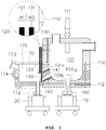
- As illustrated in
FIG. 1 , the plasma furnace of the present invention comprises afurnace body 110; and aheating portion lateral discharge gate melting chamber 101 for accommodating molten material, and twolateral discharge gates melting chamber 101. - The
furnace body 110 may be made using a material with a high thermal stability such as heat-resistant bricks, and acooling channel 112 is formed in the inside of thefurnace body 110. Accordingly, the outer surface of thefurnace body 110 can be cooled and maintained at a proper temperature below 60 °C by circulation of cooling water. - The
furnace body 110 provides melting heat for melting the introduced waste by an installedplasma torch 111. Theplasma torch 111 is installed at the upper end of themelting chamber 101 of thefurnace body 110 and a dual plasma torch capable of transferred or non-transferred operation may be provided. Electrodes (not shown) for transferred operation may be provided at the lower portion of the melting chamber, and the melting efficiency can be maximized by using the Joule's heat and torch frame temperature and arc heat. - A melt discharge portion is provided in the lower portion of the
furnace body 110, and in particular, the melt discharge portion is provided by a dam-type discharge gate 150, and preferably further includes an induction heating type heater. - A
first clamp 160 may be provided at the lower end of the dam-type discharge gate 150 so as to be detachably coupled to afirst mold apparatus 10. Thefirst clamp 160 may be connected to thefirst mold apparatus 10 with a hermetic seal, Accordingly, when the molten material is discharged into thefirst mold apparatus 10, the outside air cannot flow into the inside of the furnace, and the atmosphere inside the furnace can be maintained. - On the other hand, the
first clamp 160 may be provided with a packing member such as a gasket or a synthetic rubber so that thefirst clamp 160 can be assembled with thefirst mold apparatus 10 in an airtight state. A cooling circuit may be provided to have the cooling water circulated to thefirst clamp 160 or its periphery so as to prevent degradation of the packing member due to a high temperature. - Specifically referring to
FIG. 2 , the dam-type discharge gate 150 is formed to protrude from the bottom surface of thefurnace body 110 by a predetermined height, h or more and may include aninduction coil 151 of a cylindrical shape provided to surround thelower outlet 150a, and anexhaust tube 152, that is, an electric conductor for indirect induction heating fixed inside theinduction coil 151. - Accordingly, even if the molten material in the
melting chamber 101 is completely discharged through the dam-type discharge gate 150, the molten material under a predetermined height (h) remains in themelting chamber 101 at all times. Before the waste is introduced, the inner wall of themelting chamber 101 is prevented from being directly exposed to a high temperature by the high-temperature plasma generated in theplasma torch 111 in the preheating process. - On the other hand, when the power is not applied to the
induction coil 151 at the dam-type discharge gate 150, the molten material becomes a solid in a high viscosity state to close thelower outlet 150a. When the power is applied, the solid becomes thin to be discharged to the outside through thelower outlet 150a by its own weight. - The melt discharge portion provided at the lower portion of the
furnace body 110 may be used for discharging a metal material having a large specific gravity among the molten material or for discharging the entire molten material. - Referring to
FIG. 1 andFIG. 3 , in the plasma furnace according to the present invention, thefurnace body 110 is provided with twolateral discharge gates melting chamber 101, and theheating portion lateral discharge gates - Each
lateral discharge gate hydraulic drive unit discharge flow path furnace body 110. - Each
discharge flow path furnace body 110 so that the molten material can be easily discharged to the outside by its own weight. Aheating portion discharge flow path - The
heating portion discharge flow path - In this embodiment, it is exemplified that a heating element is provided in each
discharge flow path discharge flow paths - Preferably, a
discharge chamber 170 provided at the side of thefurnace body 110 may be further comprised to accommodate the molten material discharged from eachlateral discharge gate - The
discharge chamber 170 may be an enclosed structure integrated with thefurnace body 110 or may be a detachable structure with thefurnace body 110. Meanwhile, when thedischarge chamber 170 is provided as a detachable structure with thefurnace body 110, a hermetic member may be added between thedischarge chamber 170 and thefurnace body 110 to maintain a hermetic seal. - The
discharge chamber 170 is provided with aslag outlet 171 at a lower portion thereof and asecond clamp 172 at a lower end of theslag outlet 171 to which thesecond mold apparatus 20 is detachably coupled. Thesecond clamp 172 is connected to thesecond mold apparatus 20 with a hermetic seal. Accordingly, when the molten material, slag is discharged into thesecond mold apparatus 20, outside air cannot flow into the discharge chamber and the atmosphere inside the furnace can be maintained. - The
second clamp 172 may be provided with a packing member such as a gasket or a synthetic rubber so that thesecond clamp 172 can be assembled with thesecond mold apparatus 20 in an airtight state. A cooling circuit may be provided to have the cooling water circulated to thesecond clamp 172 or the periphery thereof so as to prevent degradation of the packing member due to a high temperature. - The
discharge chamber 170 may be provided with anobservation window 173 for observing thedischarge gate - The
discharge chamber 170 may be provided with adoor 174 that can be opened and closed at the front thereof so as to be able to collect a sample when the molten material is discharged. In thedischarge chamber 170, a heating means 175 may be provided so as to control the temperature inside thedischarge chamber 170. Such a heating means 175 may be provided by molybdenum disilicide, MoSi2, which is effective as a heating element even at a high temperature of 1,500°C or higher. - In this embodiment, the
lateral discharge gate furnace body 110 to be opened and closed. However, the lateral discharge gate may be provided inside the furnace body or in the melting chamber to discharge the molten material. -
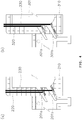
FIG. 4(a) (b) shows a lateral discharge gate of the plasma furnace according to other embodiments. - As illustrated in
FIG. 4(a) , twolateral discharge gates furnace body 210 so as to move up and down to open and close thedischarge flow path 201a, 201b. - As illustrated in FIG. 4(c), two
lateral discharge gates furnace body 310 to control the discharge of molten material from themelting chamber 301 into thedischarge flow path 301a, 301b. - As mentioned above, the lateral discharge gate can have a variety of layouts, and preferably is located outside the furnace body.
- Referring to
FIG. 1 , twolateral discharge gates lateral discharge gate channel 112 provided in thefurnace body 110 can be eliminated. - It will be apparent to those skilled in the art that the present invention is not limited to the aforementioned embodiments and accompanying drawings, and various modifications and variations can be made in the present invention without departing from the spirit or scope of the general inventive concept as defined by the appended claims.
-
- 101a, 101b : discharge flow path 110 : furnace body
- 111 : plasma torch 112 : cooling channel
- 120, 130 :
lateral discharge gate 141, 142 : heating portion - 150 : dam-type discharge gate 160 : first clamp
- 170 : discharge chamber 171 : slag outlet
- 172 : second clamp 173 : observation window
- 174 : door 175 : heating means
Claims (7)
- A plasma furnace comprising:a furnace body; anda heating portion,wherein the furnace body comprises a melt discharge portion formed through a lower portion of the melting chamber provided for accommodating molten material; and at least two lateral discharge gates provided at different heights capable of discharging molten material, andwherein the heating portion is capable of heating the lateral discharge gate.
- The plasma furnace according to claim 1,
wherein the melt discharge portion comprises a dam type discharge gate provided to protrude on the lower portion of the melting chamber to discharge the molten material above a predefined height. - The plasma furnace according to claim 2,
wherein the dam type discharge gate further comprises an induction heater. - The plasma furnace according to claim 1,
wherein the lateral discharge gate is moved up and down with respect to the furnace body to open and close a discharge flow path. - The plasma furnace according to claim 1, further comprising:
a discharge chamber provided on the lateral portion of the furnace body for accommodating the discharged melt along the lateral discharge gate and having an outlet at the lower portion. - The plasma furnace according to claim 5,
wherein the discharge chamber further comprise a window for observing the inside of the furnace. - The plasma furnace according to claim 5 or claim 6, wherein the discharge chamber further comprise a door that can be opened and closed.
Applications Claiming Priority (2)
| Application Number | Priority Date | Filing Date | Title |
|---|---|---|---|
| KR1020150114045A KR101617167B1 (en) | 2015-08-12 | 2015-08-12 | Plasma melter having side discharge gates |
| PCT/KR2015/008580 WO2017026562A1 (en) | 2015-08-12 | 2015-08-18 | Plasma melting furnace having lateral discharge gates |
Publications (3)
| Publication Number | Publication Date |
|---|---|
| EP3336854A1 true EP3336854A1 (en) | 2018-06-20 |
| EP3336854A4 EP3336854A4 (en) | 2018-12-19 |
| EP3336854B1 EP3336854B1 (en) | 2021-01-20 |
Family
ID=56022679
Family Applications (1)
| Application Number | Title | Priority Date | Filing Date |
|---|---|---|---|
| EP15901044.6A Active EP3336854B1 (en) | 2015-08-12 | 2015-08-18 | Plasma melting furnace having lateral discharge gates |
Country Status (6)
| Country | Link |
|---|---|
| US (1) | US10914523B2 (en) |
| EP (1) | EP3336854B1 (en) |
| JP (2) | JP2018521294A (en) |
| KR (1) | KR101617167B1 (en) |
| CN (1) | CN107924728A (en) |
| WO (1) | WO2017026562A1 (en) |
Families Citing this family (6)
| Publication number | Priority date | Publication date | Assignee | Title |
|---|---|---|---|---|
| KR101687660B1 (en) * | 2016-07-28 | 2016-12-21 | 주식회사 트리플 | The sealed plasma reactor for treatment of middlelow level radioactive waste |
| KR101912722B1 (en) * | 2016-11-29 | 2018-10-30 | 한국수력원자력 주식회사 | Appatus for disposing waste including an induction heating system |
| KR102122937B1 (en) | 2018-04-30 | 2020-06-15 | 한국수력원자력 주식회사 | heating system for outlet of melter |
| KR102047313B1 (en) | 2018-04-30 | 2019-11-21 | 한국수력원자력 주식회사 | Melt Discharge System |
| CN108730986A (en) * | 2018-07-12 | 2018-11-02 | 上海齐耀热能工程有限公司 | Fixed-end forces device |
| JP2021170511A (en) | 2020-04-17 | 2021-10-28 | 株式会社エンビジョンAescジャパン | Residual capacity estimation device, model generation device, residual capacity estimation method, model generation method, and program |
Family Cites Families (37)
| Publication number | Priority date | Publication date | Assignee | Title |
|---|---|---|---|---|
| US3744438A (en) * | 1968-12-24 | 1973-07-10 | Pyro Magnetics Corp | Incinerating |
| DE3373170D1 (en) * | 1982-05-25 | 1987-09-24 | Johnson Matthey Plc | Plasma arc furnace |
| US4655437A (en) * | 1985-05-03 | 1987-04-07 | Huron Valley Steel Corp. | Apparatus for simultaneously separating volatile and non-volatile metals |
| CA1278431C (en) * | 1985-09-26 | 1991-01-02 | Nicholas Adrian Barcza | Thermal production of magnesium |
| JPH0480514A (en) | 1990-07-24 | 1992-03-13 | Daido Steel Co Ltd | Base metal taking device for arc furnace for melting process |
| DE4024700A1 (en) * | 1990-08-03 | 1992-02-06 | Telefunken Systemtechnik | Refuse treatment plant - is hermetically sealed under negative pressure with ionic reduction of waste gases and with gas treatment |
| JPH06502220A (en) * | 1990-11-14 | 1994-03-10 | ミンプロック テクノロジー プロプライエタリー リミテッド | Direct sulfurization of zinc |
| US5280757A (en) * | 1992-04-13 | 1994-01-25 | Carter George W | Municipal solid waste disposal process |
| US5579705A (en) * | 1993-03-08 | 1996-12-03 | Kabushiki Kaisha Kobe Seiko Sho | Plasma furnace and a method of operating the same |
| FR2710861B1 (en) * | 1993-10-08 | 1995-11-03 | Commissariat Energie Atomique | Method of incineration and vitrification of waste in a crucible. |
| WO1995014191A1 (en) * | 1993-11-19 | 1995-05-26 | Phoenix Environmental, Ltd. | System for converting solid waste material into environmentally safe products |
| US5673285A (en) * | 1994-06-27 | 1997-09-30 | Electro-Pyrolysis, Inc. | Concentric electrode DC arc systems and their use in processing waste materials |
| US5690888A (en) * | 1995-06-07 | 1997-11-25 | Molten Metal Technologies, Inc. | Apparatus and method for tapping a reactor containing a molten fluid |
| KR200343807Y1 (en) | 1998-12-30 | 2004-05-17 | 삼성중공업 주식회사 | Plasma melting furnace |
| KR100334439B1 (en) * | 1998-12-30 | 2002-08-28 | 삼성중공업 주식회사 | Plasma Melting Furnace Slag Discharge Device |
| JP2001050530A (en) | 1999-08-05 | 2001-02-23 | Nkk Corp | Melting processing method for incinerated residue containing salts and its melting furnace |
| KR100415801B1 (en) * | 2003-04-14 | 2004-01-24 | 주식회사 케이비 엔텍 | Method for melting of sludge and apparatus |
| JP3860135B2 (en) * | 2003-04-30 | 2006-12-20 | 株式会社メイチュー | Metal melting furnace |
| US6971323B2 (en) | 2004-03-19 | 2005-12-06 | Peat International, Inc. | Method and apparatus for treating waste |
| CN2869728Y (en) * | 2005-11-15 | 2007-02-14 | 宁波金田铜业(集团)股份有限公司 | Non-ferrous metal smelting, heat-insulating composite furnace |
| JP4949074B2 (en) * | 2007-02-23 | 2012-06-06 | 三菱重工環境・化学エンジニアリング株式会社 | Method and apparatus for controlling operation of plasma melting furnace |
| ES2334870B1 (en) * | 2007-10-04 | 2011-01-03 | Consejo Superior De Investigaciones Cientificas | MODIFIED INDUCTION OVEN FOR THE ELIMINATION OF SIDERURGICAL WASTE WITH CINC WITH RECOVERY OF ITS METALS. |
| KR101032055B1 (en) | 2008-11-26 | 2011-05-02 | 지에스플라텍 주식회사 | Apparatus and method for tapping melts in plasma torch melter |
| JP5391770B2 (en) | 2009-03-25 | 2014-01-15 | Jfeエンジニアリング株式会社 | Waste treatment apparatus and waste treatment method |
| KR20110113223A (en) * | 2010-04-09 | 2011-10-17 | 정정철 | The method of manufacture for iron lump of iron dust used plasma |
| KR101188210B1 (en) | 2010-08-03 | 2012-10-05 | 인하대학교 산학협력단 | Preemtive priority-based Ethernet data scheduling and The System using it |
| JP2012132631A (en) | 2010-12-22 | 2012-07-12 | Tokai Konetsu Kogyo Co Ltd | Melting furnace |
| KR20120128752A (en) * | 2011-05-18 | 2012-11-28 | 주식회사 플라즈마 그린 테크놀러지 | Treatment Equipment and Method of Radioactivity Waste by Plasma |
| KR101277817B1 (en) * | 2011-09-30 | 2013-06-21 | 주식회사 서울엔지니어링 | Door Manufacturing Method for Discharging a Slag |
| JP2013101088A (en) | 2011-11-10 | 2013-05-23 | Ngk Insulators Ltd | Radioactive waste incinerator and radioactive waste incineration processing method |
| KR101330970B1 (en) * | 2011-11-29 | 2013-11-18 | 현대제철 주식회사 | Device for recovering valuable metal and producing of multi-functional aggregate using slag |
| CN202350509U (en) * | 2011-12-14 | 2012-07-25 | 北京建筑工程学院 | Natural gas non-flame catalytic combustion kiln with near zero pollutant emission |
| SE537235C2 (en) * | 2012-09-21 | 2015-03-10 | Valeas Recycling Ab | Process and arrangement for the recovery of vaporizable substances from a slag by means of plasma induced vaporization |
| KR101457368B1 (en) * | 2013-10-04 | 2014-11-03 | 한국수력원자력 주식회사 | Induction Tapping Equipment and Method for Melt |
| CN103833035B (en) * | 2014-03-06 | 2017-01-11 | 台州市一能科技有限公司 | Preparation method of silicon carbide |
| KR101418105B1 (en) * | 2014-04-24 | 2014-07-11 | 주식회사 플라즈마 그린 테크놀로지 | Plasma torch-typed melting apparatus for manufacturing stone wool products using mineral waste, and method for manufacturing stone wool products utilizing the same |
| EP3331825A4 (en) * | 2015-08-07 | 2019-03-20 | HPQ-Silicon Resources Inc. | Silica to high purity silicon production process |
-
2015
- 2015-08-12 KR KR1020150114045A patent/KR101617167B1/en active IP Right Grant
- 2015-08-18 CN CN201580082296.9A patent/CN107924728A/en active Pending
- 2015-08-18 EP EP15901044.6A patent/EP3336854B1/en active Active
- 2015-08-18 JP JP2018504290A patent/JP2018521294A/en active Pending
- 2015-08-18 US US15/750,278 patent/US10914523B2/en active Active
- 2015-08-18 WO PCT/KR2015/008580 patent/WO2017026562A1/en active Application Filing
-
2019
- 2019-12-26 JP JP2019236022A patent/JP2020073844A/en active Pending
Also Published As
| Publication number | Publication date |
|---|---|
| KR101617167B1 (en) | 2016-05-03 |
| JP2020073844A (en) | 2020-05-14 |
| JP2018521294A (en) | 2018-08-02 |
| EP3336854B1 (en) | 2021-01-20 |
| WO2017026562A1 (en) | 2017-02-16 |
| CN107924728A (en) | 2018-04-17 |
| US10914523B2 (en) | 2021-02-09 |
| US20180363982A1 (en) | 2018-12-20 |
| EP3336854A4 (en) | 2018-12-19 |
Similar Documents
| Publication | Publication Date | Title |
|---|---|---|
| EP3336854A1 (en) | Plasma melting furnace having lateral discharge gates | |
| JP3672942B2 (en) | Apparatus for extraction by pouring at a controlled flow rate of material melted in a melting furnace with cooling walls | |
| CN205382196U (en) | Zinc -tin vacuum distillation stove | |
| JP2013028482A (en) | Method for operating glass melting furnace and glass melting furnace | |
| KR101680821B1 (en) | Melt discharger having slit | |
| CN215391537U (en) | Melting furnace and slurry discharge device | |
| KR100759311B1 (en) | Furnace with easy removable refractory | |
| US10861613B2 (en) | Plasma furnace | |
| US20160091249A1 (en) | Crucibles for melting material and methods of transferring material therefrom | |
| KR20180137681A (en) | Melt discharger having nitrogen cooling structure | |
| KR101534663B1 (en) | Apparatus for preheating pot roll unit | |
| KR101474220B1 (en) | Furnace for melting Aluminum Puck by Precipitation | |
| JP5754773B2 (en) | Heating container, local heating device and heating method | |
| CN214199701U (en) | Melt water-cooling furnace | |
| KR101728302B1 (en) | Melt discharger having cooling structure and method of discharging melt using the same | |
| CN105274367B (en) | Magnesium alloy protective gas melting device | |
| TR2023004620U5 (en) | INDIRECT GAS HEATED LINE SYSTEM | |
| KR200461167Y1 (en) | apparatus for fixing holder for tap-hole of electric furnace | |
| RU2619458C1 (en) | Cold tigel | |
| KR20160050117A (en) | Door apparatus for discharging slag | |
| JP5621840B2 (en) | Electromagnetic nozzle device for hot water of cold crucible melting furnace and hot water method | |
| JP2013100981A (en) | Tapping electromagnetic nozzle device of cold crucible melting furnace | |
| CN113560318A (en) | Melting furnace and slurry discharge device | |
| RU23672U1 (en) | Crucible furnace | |
| RU2330391C2 (en) | Electrode and method of electrode assembly in electric arc furnace |
Legal Events
| Date | Code | Title | Description |
|---|---|---|---|
| STAA | Information on the status of an ep patent application or granted ep patent |
Free format text: STATUS: THE INTERNATIONAL PUBLICATION HAS BEEN MADE |
|
| PUAI | Public reference made under article 153(3) epc to a published international application that has entered the european phase |
Free format text: ORIGINAL CODE: 0009012 |
|
| STAA | Information on the status of an ep patent application or granted ep patent |
Free format text: STATUS: REQUEST FOR EXAMINATION WAS MADE |
|
| 17P | Request for examination filed |
Effective date: 20180312 |
|
| AK | Designated contracting states |
Kind code of ref document: A1 Designated state(s): AL AT BE BG CH CY CZ DE DK EE ES FI FR GB GR HR HU IE IS IT LI LT LU LV MC MK MT NL NO PL PT RO RS SE SI SK SM TR |
|
| AX | Request for extension of the european patent |
Extension state: BA ME |
|
| DAV | Request for validation of the european patent (deleted) | ||
| DAX | Request for extension of the european patent (deleted) | ||
| A4 | Supplementary search report drawn up and despatched |
Effective date: 20181119 |
|
| RIC1 | Information provided on ipc code assigned before grant |
Ipc: F27B 3/19 20060101ALI20181113BHEP Ipc: F27B 3/10 20060101ALI20181113BHEP Ipc: G21F 9/30 20060101AFI20181113BHEP Ipc: F27D 99/00 20100101ALI20181113BHEP Ipc: F27B 17/00 20060101ALI20181113BHEP Ipc: F23G 5/08 20060101ALI20181113BHEP |
|
| STAA | Information on the status of an ep patent application or granted ep patent |
Free format text: STATUS: EXAMINATION IS IN PROGRESS |
|
| 17Q | First examination report despatched |
Effective date: 20190724 |
|
| REG | Reference to a national code |
Ref country code: DE Ref legal event code: R079 Ref document number: 602015065110 Country of ref document: DE Free format text: PREVIOUS MAIN CLASS: G21F0009300000 Ipc: F27D0003140000 |
|
| GRAP | Despatch of communication of intention to grant a patent |
Free format text: ORIGINAL CODE: EPIDOSNIGR1 |
|
| STAA | Information on the status of an ep patent application or granted ep patent |
Free format text: STATUS: GRANT OF PATENT IS INTENDED |
|
| RIC1 | Information provided on ipc code assigned before grant |
Ipc: F27D 3/14 20060101AFI20200720BHEP Ipc: F27B 17/00 20060101ALI20200720BHEP Ipc: F27B 3/10 20060101ALI20200720BHEP Ipc: F27B 3/19 20060101ALI20200720BHEP Ipc: F27D 99/00 20100101ALI20200720BHEP Ipc: F23G 5/08 20060101ALI20200720BHEP Ipc: G21F 9/30 20060101ALI20200720BHEP |
|
| INTG | Intention to grant announced |
Effective date: 20200810 |
|
| RAP1 | Party data changed (applicant data changed or rights of an application transferred) |
Owner name: KOREA HYDRO & NUCLEAR POWER CO., LTD |
|
| GRAS | Grant fee paid |
Free format text: ORIGINAL CODE: EPIDOSNIGR3 |
|
| GRAA | (expected) grant |
Free format text: ORIGINAL CODE: 0009210 |
|
| STAA | Information on the status of an ep patent application or granted ep patent |
Free format text: STATUS: THE PATENT HAS BEEN GRANTED |
|
| AK | Designated contracting states |
Kind code of ref document: B1 Designated state(s): AL AT BE BG CH CY CZ DE DK EE ES FI FR GB GR HR HU IE IS IT LI LT LU LV MC MK MT NL NO PL PT RO RS SE SI SK SM TR |
|
| REG | Reference to a national code |
Ref country code: GB Ref legal event code: FG4D |
|
| REG | Reference to a national code |
Ref country code: CH Ref legal event code: EP |
|
| REG | Reference to a national code |
Ref country code: DE Ref legal event code: R096 Ref document number: 602015065110 Country of ref document: DE |
|
| REG | Reference to a national code |
Ref country code: AT Ref legal event code: REF Ref document number: 1356769 Country of ref document: AT Kind code of ref document: T Effective date: 20210215 |
|
| REG | Reference to a national code |
Ref country code: IE Ref legal event code: FG4D |
|
| REG | Reference to a national code |
Ref country code: NL Ref legal event code: MP Effective date: 20210120 |
|
| REG | Reference to a national code |
Ref country code: LT Ref legal event code: MG9D |
|
| REG | Reference to a national code |
Ref country code: AT Ref legal event code: MK05 Ref document number: 1356769 Country of ref document: AT Kind code of ref document: T Effective date: 20210120 |
|
| PG25 | Lapsed in a contracting state [announced via postgrant information from national office to epo] |
Ref country code: PT Free format text: LAPSE BECAUSE OF FAILURE TO SUBMIT A TRANSLATION OF THE DESCRIPTION OR TO PAY THE FEE WITHIN THE PRESCRIBED TIME-LIMIT Effective date: 20210520 Ref country code: NO Free format text: LAPSE BECAUSE OF FAILURE TO SUBMIT A TRANSLATION OF THE DESCRIPTION OR TO PAY THE FEE WITHIN THE PRESCRIBED TIME-LIMIT Effective date: 20210420 Ref country code: LT Free format text: LAPSE BECAUSE OF FAILURE TO SUBMIT A TRANSLATION OF THE DESCRIPTION OR TO PAY THE FEE WITHIN THE PRESCRIBED TIME-LIMIT Effective date: 20210120 Ref country code: GR Free format text: LAPSE BECAUSE OF FAILURE TO SUBMIT A TRANSLATION OF THE DESCRIPTION OR TO PAY THE FEE WITHIN THE PRESCRIBED TIME-LIMIT Effective date: 20210421 Ref country code: HR Free format text: LAPSE BECAUSE OF FAILURE TO SUBMIT A TRANSLATION OF THE DESCRIPTION OR TO PAY THE FEE WITHIN THE PRESCRIBED TIME-LIMIT Effective date: 20210120 Ref country code: FI Free format text: LAPSE BECAUSE OF FAILURE TO SUBMIT A TRANSLATION OF THE DESCRIPTION OR TO PAY THE FEE WITHIN THE PRESCRIBED TIME-LIMIT Effective date: 20210120 Ref country code: BG Free format text: LAPSE BECAUSE OF FAILURE TO SUBMIT A TRANSLATION OF THE DESCRIPTION OR TO PAY THE FEE WITHIN THE PRESCRIBED TIME-LIMIT Effective date: 20210420 |
|
| PG25 | Lapsed in a contracting state [announced via postgrant information from national office to epo] |
Ref country code: AT Free format text: LAPSE BECAUSE OF FAILURE TO SUBMIT A TRANSLATION OF THE DESCRIPTION OR TO PAY THE FEE WITHIN THE PRESCRIBED TIME-LIMIT Effective date: 20210120 Ref country code: PL Free format text: LAPSE BECAUSE OF FAILURE TO SUBMIT A TRANSLATION OF THE DESCRIPTION OR TO PAY THE FEE WITHIN THE PRESCRIBED TIME-LIMIT Effective date: 20210120 Ref country code: LV Free format text: LAPSE BECAUSE OF FAILURE TO SUBMIT A TRANSLATION OF THE DESCRIPTION OR TO PAY THE FEE WITHIN THE PRESCRIBED TIME-LIMIT Effective date: 20210120 Ref country code: RS Free format text: LAPSE BECAUSE OF FAILURE TO SUBMIT A TRANSLATION OF THE DESCRIPTION OR TO PAY THE FEE WITHIN THE PRESCRIBED TIME-LIMIT Effective date: 20210120 Ref country code: SE Free format text: LAPSE BECAUSE OF FAILURE TO SUBMIT A TRANSLATION OF THE DESCRIPTION OR TO PAY THE FEE WITHIN THE PRESCRIBED TIME-LIMIT Effective date: 20210120 |
|
| PG25 | Lapsed in a contracting state [announced via postgrant information from national office to epo] |
Ref country code: IS Free format text: LAPSE BECAUSE OF FAILURE TO SUBMIT A TRANSLATION OF THE DESCRIPTION OR TO PAY THE FEE WITHIN THE PRESCRIBED TIME-LIMIT Effective date: 20210520 |
|
| REG | Reference to a national code |
Ref country code: DE Ref legal event code: R097 Ref document number: 602015065110 Country of ref document: DE |
|
| PG25 | Lapsed in a contracting state [announced via postgrant information from national office to epo] |
Ref country code: EE Free format text: LAPSE BECAUSE OF FAILURE TO SUBMIT A TRANSLATION OF THE DESCRIPTION OR TO PAY THE FEE WITHIN THE PRESCRIBED TIME-LIMIT Effective date: 20210120 Ref country code: CZ Free format text: LAPSE BECAUSE OF FAILURE TO SUBMIT A TRANSLATION OF THE DESCRIPTION OR TO PAY THE FEE WITHIN THE PRESCRIBED TIME-LIMIT Effective date: 20210120 Ref country code: SM Free format text: LAPSE BECAUSE OF FAILURE TO SUBMIT A TRANSLATION OF THE DESCRIPTION OR TO PAY THE FEE WITHIN THE PRESCRIBED TIME-LIMIT Effective date: 20210120 |
|
| PLBE | No opposition filed within time limit |
Free format text: ORIGINAL CODE: 0009261 |
|
| STAA | Information on the status of an ep patent application or granted ep patent |
Free format text: STATUS: NO OPPOSITION FILED WITHIN TIME LIMIT |
|
| PG25 | Lapsed in a contracting state [announced via postgrant information from national office to epo] |
Ref country code: SK Free format text: LAPSE BECAUSE OF FAILURE TO SUBMIT A TRANSLATION OF THE DESCRIPTION OR TO PAY THE FEE WITHIN THE PRESCRIBED TIME-LIMIT Effective date: 20210120 Ref country code: DK Free format text: LAPSE BECAUSE OF FAILURE TO SUBMIT A TRANSLATION OF THE DESCRIPTION OR TO PAY THE FEE WITHIN THE PRESCRIBED TIME-LIMIT Effective date: 20210120 Ref country code: RO Free format text: LAPSE BECAUSE OF FAILURE TO SUBMIT A TRANSLATION OF THE DESCRIPTION OR TO PAY THE FEE WITHIN THE PRESCRIBED TIME-LIMIT Effective date: 20210120 |
|
| 26N | No opposition filed |
Effective date: 20211021 |
|
| PG25 | Lapsed in a contracting state [announced via postgrant information from national office to epo] |
Ref country code: ES Free format text: LAPSE BECAUSE OF FAILURE TO SUBMIT A TRANSLATION OF THE DESCRIPTION OR TO PAY THE FEE WITHIN THE PRESCRIBED TIME-LIMIT Effective date: 20210120 Ref country code: AL Free format text: LAPSE BECAUSE OF FAILURE TO SUBMIT A TRANSLATION OF THE DESCRIPTION OR TO PAY THE FEE WITHIN THE PRESCRIBED TIME-LIMIT Effective date: 20210120 |
|
| PG25 | Lapsed in a contracting state [announced via postgrant information from national office to epo] |
Ref country code: SI Free format text: LAPSE BECAUSE OF FAILURE TO SUBMIT A TRANSLATION OF THE DESCRIPTION OR TO PAY THE FEE WITHIN THE PRESCRIBED TIME-LIMIT Effective date: 20210120 |
|
| REG | Reference to a national code |
Ref country code: DE Ref legal event code: R119 Ref document number: 602015065110 Country of ref document: DE |
|
| PG25 | Lapsed in a contracting state [announced via postgrant information from national office to epo] |
Ref country code: MC Free format text: LAPSE BECAUSE OF FAILURE TO SUBMIT A TRANSLATION OF THE DESCRIPTION OR TO PAY THE FEE WITHIN THE PRESCRIBED TIME-LIMIT Effective date: 20210120 |
|
| REG | Reference to a national code |
Ref country code: BE Ref legal event code: MM Effective date: 20210831 |
|
| PG25 | Lapsed in a contracting state [announced via postgrant information from national office to epo] |
Ref country code: IT Free format text: LAPSE BECAUSE OF FAILURE TO SUBMIT A TRANSLATION OF THE DESCRIPTION OR TO PAY THE FEE WITHIN THE PRESCRIBED TIME-LIMIT Effective date: 20210120 |
|
| PG25 | Lapsed in a contracting state [announced via postgrant information from national office to epo] |
Ref country code: IS Free format text: LAPSE BECAUSE OF FAILURE TO SUBMIT A TRANSLATION OF THE DESCRIPTION OR TO PAY THE FEE WITHIN THE PRESCRIBED TIME-LIMIT Effective date: 20210520 Ref country code: LU Free format text: LAPSE BECAUSE OF NON-PAYMENT OF DUE FEES Effective date: 20210818 |
|
| PG25 | Lapsed in a contracting state [announced via postgrant information from national office to epo] |
Ref country code: IE Free format text: LAPSE BECAUSE OF NON-PAYMENT OF DUE FEES Effective date: 20210818 Ref country code: FR Free format text: LAPSE BECAUSE OF NON-PAYMENT OF DUE FEES Effective date: 20210831 Ref country code: DE Free format text: LAPSE BECAUSE OF NON-PAYMENT OF DUE FEES Effective date: 20220301 Ref country code: BE Free format text: LAPSE BECAUSE OF NON-PAYMENT OF DUE FEES Effective date: 20210831 |
|
| PG25 | Lapsed in a contracting state [announced via postgrant information from national office to epo] |
Ref country code: HU Free format text: LAPSE BECAUSE OF FAILURE TO SUBMIT A TRANSLATION OF THE DESCRIPTION OR TO PAY THE FEE WITHIN THE PRESCRIBED TIME-LIMIT; INVALID AB INITIO Effective date: 20150818 |
|
| PG25 | Lapsed in a contracting state [announced via postgrant information from national office to epo] |
Ref country code: NL Free format text: LAPSE BECAUSE OF NON-PAYMENT OF DUE FEES Effective date: 20210120 Ref country code: CY Free format text: LAPSE BECAUSE OF FAILURE TO SUBMIT A TRANSLATION OF THE DESCRIPTION OR TO PAY THE FEE WITHIN THE PRESCRIBED TIME-LIMIT Effective date: 20210120 |
|
| PGFP | Annual fee paid to national office [announced via postgrant information from national office to epo] |
Ref country code: GB Payment date: 20230824 Year of fee payment: 9 Ref country code: CH Payment date: 20230902 Year of fee payment: 9 |
|
| PG25 | Lapsed in a contracting state [announced via postgrant information from national office to epo] |
Ref country code: MK Free format text: LAPSE BECAUSE OF FAILURE TO SUBMIT A TRANSLATION OF THE DESCRIPTION OR TO PAY THE FEE WITHIN THE PRESCRIBED TIME-LIMIT Effective date: 20210120 |