EP3336853A1 - Apparatus for filtering radioactive materials - Google Patents
Apparatus for filtering radioactive materials Download PDFInfo
- Publication number
- EP3336853A1 EP3336853A1 EP15901040.4A EP15901040A EP3336853A1 EP 3336853 A1 EP3336853 A1 EP 3336853A1 EP 15901040 A EP15901040 A EP 15901040A EP 3336853 A1 EP3336853 A1 EP 3336853A1
- Authority
- EP
- European Patent Office
- Prior art keywords
- radioactive
- filtering
- filter
- radioactive gas
- gas
- Prior art date
- Legal status (The legal status is an assumption and is not a legal conclusion. Google has not performed a legal analysis and makes no representation as to the accuracy of the status listed.)
- Granted
Links
Images


Classifications
-
- B—PERFORMING OPERATIONS; TRANSPORTING
- B01—PHYSICAL OR CHEMICAL PROCESSES OR APPARATUS IN GENERAL
- B01D—SEPARATION
- B01D49/00—Separating dispersed particles from gases, air or vapours by other methods
- B01D49/003—Separating dispersed particles from gases, air or vapours by other methods by sedimentation
-
- G—PHYSICS
- G21—NUCLEAR PHYSICS; NUCLEAR ENGINEERING
- G21F—PROTECTION AGAINST X-RADIATION, GAMMA RADIATION, CORPUSCULAR RADIATION OR PARTICLE BOMBARDMENT; TREATING RADIOACTIVELY CONTAMINATED MATERIAL; DECONTAMINATION ARRANGEMENTS THEREFOR
- G21F9/00—Treating radioactively contaminated material; Decontamination arrangements therefor
- G21F9/02—Treating gases
Definitions
- the present invention relates to an apparatus for filtering a radioactive gas generated from nuclear fuel leaked when an accident occurs in a nuclear power plant, and more particularly, to a filtration apparatus capable of preventing contamination inside the containment building.
- Radioactive contamination refers to the accumulation or presence of radioactive material on the interior or surface of solid, liquid, or gas. This radioactive contamination poses a risk from the radioactive decay of the contaminant, which, releases harmful ionizing radiation such as ⁇ , particles, rays or neutrons. Air, soil, people, plants and animals are contaminated by nuclear fuel and fission products following the atomic bombing of nuclear weapons or destruction of reactor containment buildings. Examples include Bikini Atoll, the Rocky Platt Factory in Colorado, the Fukushima Daiichi Nuclear Power Plant accident, and the Chernobyl nuclear power plant accident. Therefore, it is indispensable to have a filtration device that is required to respond early to radioactive material in the event of an accident in a nuclear power plant.
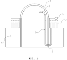
- Korean Patent Laid-Open Publication No. 2014-0062654 discloses a filtration and exhaust system for filtering radioactive material. Referring to FIG.
- the filtration and exhaust system comprises an inlet 2 for introducing a steam-gas mixture to solve the complexity of the system due to the installation of a separate filtration tank and a number of valves in the system, a U-shaped inflow pipe 6 connected to the inlet 2 for forming the appropriate head pressure, a cooling water tank 3 connected to the inflow pipe 6 for filtering the steam-gas mixture with cooling water, and a filtration device 5 installed on the top of the cooling water tank for filtering the radioactive substance that is not filtered by the cooling water.
- the filtration and exhaust system of the prior art has a problem that the components and the atmosphere in the containment building are contaminated before the radioactive material generated in the reactor cavity is discharged to the outside of the building, and accordingly there is a further demand for decontamination in the containment building.
- the present invention aims at filtering the radioactive gas generated from the core melt before it is diffused from inside the reactor cavity to the containment building atmosphere.
- the present invention provides an apparatus for filtering radioactive material comprising a suction pipe for introducing radioactive gas generated from a core melt by the pressure inside a reactor cavity, and a filtration unit for removing radioactive material in a radioactive gas introduced into the suction pipe by a stepwise dry and wet process and discharging the gas to the outside the containment building, wherein the suction pipe is connected at one end to the outer peripheral surface of the upper portion of the reactor cavity and the filtration unit is installed inside the reactor building.
- the filtration unit may comprise a dry filter for filtering the radioactive material in the form of particles by causing a difference in the rate of movement between the substances in the radioactive gas.
- the dry filter is provided with a connection pipe in its upper portion for discharging the radioactive gas of which the particle type radioactive material has been filtered after the dry process, and the other end of the suction pipe being connected to the lower portion. Accordingly, the difference in the rate of movement between materials can be caused by heat rise of the radioactive gas introduced into the suction pipe.
- the dry filter may be provided with a filter forming a layered structure therein to increase the movement path of the radioactive gas.
- the filtration unit may be provided with a wet filter for filtering the particulate radioactive material as the discharged radioactive gas flows into the cooling water after the dry process so as to agglomerate the substances in the radioactive gas.
- the filtration unit may comprise a connection pipe for introducing the radioactive gas after a dry process into the wet filter, and the connection pipe is formed with a recessed portion in which the inner diameter is decreased and the inner pressure is increased so as to extrude the introduced radioactive gas toward the wet filter.
- the filtration unit is disposed between the reactor cavity and the atmosphere of the containment building to prevent the radioactive gas from diffusing into the containment building atmosphere.
- the present invention is advantageous in that the filtration unit can filter the radioactive material by a stepwise dry and wet process and thereby effectively decontaminating the radioactive gas.
- the present invention is advantageous in that the dry filter can primarily filter the relatively large particle type of radioactive material without a separate power source by using the difference in the traveling speed between the substances in the radioactive gas.
- the present invention is advantageous in that, as the recessed portion is formed in the connection pipe, the primarily filtered radioactive gas can be effectively extruded into the wet filter.
- FIG. 2 shows an apparatus for filtering radioactive material according to an embodiment of the present invention.
- the apparatus for filtering radioactive material may comprise a suction pipe 33 and a filtration unit 10.
- the apparatus for filtering radioactive material may be installed in connection with the reactor cavity 90 outside the reactor pressure vessel 70.
- the suction pipe 33 is capable of sucking the radioactive gas generated from the core melt by the pressure inside the reactor cavity 90.
- One end of the suction pipe 33 is connected to the upper outer circumferential surface of the reactor cavity 90 and the other end of the suction pipe 33 is connected to the dry filter 30 in the filtration unit 10.
- the reactor cavity 90 serves as a pressure barrier when the radiant gas is released with the hot steam and is the final barrier to the dissipation of the radiant gas.
- the gas pressure generated in the reactor cavity 90 pushes the radioactive gas to the suction pipe 33.
- other pipes formed in the reactor cavity 90 can be designed by finishing touches such that all the gas pressure can be applied to the suction pipe 33.
- the suction pipe 33 can suck the radioactive gas by the pressure of the reactor cavity 90 and deliver the radioactive gas to the filtration unit 10 without the help of a separate pump or the like.
- the dry filter 30 can filter the particulate radioactive material by generating a difference in the traveling speed between the substances in the radioactive gas.
- the dry filter 30 is connected to the lower end of the suction pipe 33 and has a connection pipe 35 in the upper portion for discharging the radioactive gas in which the particle type radioactive material has been filtered after the dry process, thereby causing a difference in the traveling speed between the materials due to the heat rise of the radioactive gas introduced into the suction pipe 33.
- FIG. 3 shows the structure of the filter 31 of the dry filter 30 installed in the apparatus for filtering radioactive material according to the embodiment of the present invention.
- the radioactive gas introduced from the suction pipe 33 is diffused upward, and is discharged through the filter 31 to the outlet.
- the filter 31 may form a layered structure therein to increase the traveling path of the radioactive gas.
- the filter 31 can remove particulate contaminants from the radioactive gas diffused from the suction pipe 33.
- the filter 31 can be designed to collect contaminants from the radioactive gas and drop them down by gravity to retain the deposits.
- the filtration method of the filter 31 may be an inner filtration method in which the radioactive gas is relatively loosely filled in the mold, which is used as a filtration layer.
- the inner filtration method is suitable for the treatment of radioactive gases with a very low concentration because of its slow filtration rate.
- An in-containment refueling water storage tank (IRWST) in the containment building 11 is capable of filtering the radioactive gas discharged from the dry filter 30 by the cooling water in it.
- the refueling water storage tank (IRWST) can be built in the containment building 11 to ensure structural safety in the event of an earthquake.
- the refueling water storage tank (IRWST) 11 can be filled between the walls with compressible metal filler having a head shielding effect, and sealant can be applied on the upper portion of the refueling water storage tank to the upper portion so as to block water.
- the interior of the refueling water storage tank (IRWST) in the containment building 11 may be provided as a space independent of the arrangement of the steam generator, the reactor, and the like, and may be installed with concrete casting or steel frame.
- the refueling water storage tank (IRWST) in the containment building 11 treats the radioactive gas which has not been filtered by the dry filter 30 with the cooling water.
- the radioactive gas having passed through the dry filter 30 may undergo a phase transition in the form of liquid or solid and the contaminant in the form of minute particles smaller than the particles filtered in the dry filter 30 is not composed of a precipitate of the dry filter 30. Accordingly, the contaminant may be introduced into the wet filter 50.
- the refueling water storage tank (IRWST) in the containment building 11 introduces the unfiltered high temperature radioactive gas from the dry filter 30 through the connection pipe 35.
- the radioactive gas at a high temperature can be rapidly cooled by cooling water and condensed in solid form and deposited on the bottom.
- the cooling water supplied to the refueling water storage tank (IRWST) in the containment building 11 can be introduced from a drain port called a spillway.
- the cooling water collides with the bottom surface of the refueling water storage tank (IRWST) in the containment building 11, moves along the inner wall of the refueling water storage tank (IRWST) in the containment building 11 after a lapse of time, and can be discharged through an outlet.
- the cooling water in the refueling water storage tank (IRWST) in the containment building 11 generates a recirculating flow of cooling water on the free surface which is the upper surface where the spillway is located.
- the cooling water rapidly cools the temperature of the radioactive gas entering the refueling water storage tank (IRWST) in the containment building 11, and causes a recirculating flow to condense contaminants in the gas in a short time.
- the gas which has not been filtered in the refueling water storage tank (IRWST) in the containment building 11 can be collected at the upper portion, and the collected gas can be regarded as a gas in which most of the radioactive material is removed.
- the upper portion of the refueling water storage tank (IRWST) in the containment building 11 is coated with a sealant for blocking water and when the uncondensed gas rises and gathers at the upper portion, the finally filtered gas can be discharged outside the containment building 11.
- connection pipe 35 formed with the recessed portion may be provided so that the radioactive gas discharged from the dry filter 30 can enter the cooling water.
- the connection pipe 35 is provided to move the fluid by the pressure difference.
- a venturi nozzle may be used for the connection pipe 35 formed with the recessed portion in the present embodiment.
- connection pipe 35 in which the recessed portion is formed may have the discharging portion immersed in the cooling water.
- the introduced radioactive gas is not discharged to the outside by the connection pipe 35 immersed in the cooling water but can be precipitated by reacting with the cooling water immediately.
Landscapes
- Chemical & Material Sciences (AREA)
- Engineering & Computer Science (AREA)
- Chemical Kinetics & Catalysis (AREA)
- Physics & Mathematics (AREA)
- General Engineering & Computer Science (AREA)
- High Energy & Nuclear Physics (AREA)
- Structure Of Emergency Protection For Nuclear Reactors (AREA)
- Environmental & Geological Engineering (AREA)
- Health & Medical Sciences (AREA)
- Biomedical Technology (AREA)
- Analytical Chemistry (AREA)
- General Chemical & Material Sciences (AREA)
- Oil, Petroleum & Natural Gas (AREA)
Abstract
Description
- The present invention relates to an apparatus for filtering a radioactive gas generated from nuclear fuel leaked when an accident occurs in a nuclear power plant, and more particularly, to a filtration apparatus capable of preventing contamination inside the containment building.
- In the event of a severe accident where the core melts in the containment building, a significant amount of radioactive gas is released from the core melt. Most of the radioactive gaseous effluents of nuclear power plants are treated before they are released to the atmosphere. Current practice involves extracting radioactive particles from the effluent prior to discharging the radioactive gas effluent to the atmosphere, which requires filtration of the contaminated gas from the radioactive gas and ventilation of the building. Ventilation and purification systems can generally filter 99.9% of particles with a diameter of about 0.3 mm.
- Radioactive contamination refers to the accumulation or presence of radioactive material on the interior or surface of solid, liquid, or gas. This radioactive contamination poses a risk from the radioactive decay of the contaminant, which, releases harmful ionizing radiation such as α,particles,
 rays or neutrons. Air, soil, people, plants and animals are contaminated by nuclear fuel and fission products following the atomic bombing of nuclear weapons or destruction of reactor containment buildings. Examples include Bikini Atoll, the Rocky Platt Factory in Colorado, the Fukushima Daiichi Nuclear Power Plant accident, and the Chernobyl nuclear power plant accident. Therefore, it is indispensable to have a filtration device that is required to respond early to radioactive material in the event of an accident in a nuclear power plant.
- In this connection, Korean Patent Laid-Open Publication No.
2014-0062654 FIG. 1 , the filtration and exhaust system comprises aninlet 2 for introducing a steam-gas mixture to solve the complexity of the system due to the installation of a separate filtration tank and a number of valves in the system, aU-shaped inflow pipe 6 connected to theinlet 2 for forming the appropriate head pressure, acooling water tank 3 connected to theinflow pipe 6 for filtering the steam-gas mixture with cooling water, and afiltration device 5 installed on the top of the cooling water tank for filtering the radioactive substance that is not filtered by the cooling water. - In addition, the filtration and exhaust system of the prior art has a problem that the components and the atmosphere in the containment building are contaminated before the radioactive material generated in the reactor cavity is discharged to the outside of the building, and accordingly there is a further demand for decontamination in the containment building.
- 1. Korean Patent Publication No.
2014-0062654 - The present invention aims at filtering the radioactive gas generated from the core melt before it is diffused from inside the reactor cavity to the containment building atmosphere.
- In order to achieve the above object, the present invention provides an apparatus for filtering radioactive material comprising a suction pipe for introducing radioactive gas generated from a core melt by the pressure inside a reactor cavity, and a filtration unit for removing radioactive material in a radioactive gas introduced into the suction pipe by a stepwise dry and wet process and discharging the gas to the outside the containment building, wherein the suction pipe is connected at one end to the outer peripheral surface of the upper portion of the reactor cavity and the filtration unit is installed inside the reactor building.
- Preferably, the filtration unit may comprise a dry filter for filtering the radioactive material in the form of particles by causing a difference in the rate of movement between the substances in the radioactive gas.
- Preferably, the dry filter is provided with a connection pipe in its upper portion for discharging the radioactive gas of which the particle type radioactive material has been filtered after the dry process, and the other end of the suction pipe being connected to the lower portion. Accordingly, the difference in the rate of movement between materials can be caused by heat rise of the radioactive gas introduced into the suction pipe.
- Preferably, the dry filter may be provided with a filter forming a layered structure therein to increase the movement path of the radioactive gas.
- Preferably, the filtration unit may be provided with a wet filter for filtering the particulate radioactive material as the discharged radioactive gas flows into the cooling water after the dry process so as to agglomerate the substances in the radioactive gas.
- Preferably, the filtration unit may comprise a connection pipe for introducing the radioactive gas after a dry process into the wet filter, and the connection pipe is formed with a recessed portion in which the inner diameter is decreased and the inner pressure is increased so as to extrude the introduced radioactive gas toward the wet filter.
- According to the present invention, there is an advantage that the filtration unit is disposed between the reactor cavity and the atmosphere of the containment building to prevent the radioactive gas from diffusing into the containment building atmosphere.
- Further, the present invention is advantageous in that the filtration unit can filter the radioactive material by a stepwise dry and wet process and thereby effectively decontaminating the radioactive gas.
- Further, the present invention is advantageous in that the dry filter can primarily filter the relatively large particle type of radioactive material without a separate power source by using the difference in the traveling speed between the substances in the radioactive gas.
- In addition, the present invention is advantageous in that, as the recessed portion is formed in the connection pipe, the primarily filtered radioactive gas can be effectively extruded into the wet filter.
-
-
FIG. 1 shows a conventional filtration and exhaust system of a containment building. -
FIG. 2 shows a radioactive material filtering apparatus according to an embodiment of the present invention. -
FIG. 3 shows a filter of a dry filter according to an embodiment of the present invention. - Hereinafter, the present invention will be described in detail with reference to the accompanying drawings. However, the present invention is not limited by the exemplary embodiments. Like reference numerals in the drawings denote members performing substantially the same function
- The objects and effects of the present invention can be understood or clarified naturally by the following description, and the objects and effects of the present invention are not limited by the following description. In the following description of the present invention, a detailed description of known technologies related to the present invention will be omitted when it is determined that the gist of the present invention may be unnecessarily obscured thereby.
-
FIG. 2 shows an apparatus for filtering radioactive material according to an embodiment of the present invention. Referring toFIG. 2 , the apparatus for filtering radioactive material may comprise asuction pipe 33 and afiltration unit 10. The apparatus for filtering radioactive material may be installed in connection with thereactor cavity 90 outside thereactor pressure vessel 70. - The
suction pipe 33 is capable of sucking the radioactive gas generated from the core melt by the pressure inside thereactor cavity 90. One end of thesuction pipe 33 is connected to the upper outer circumferential surface of thereactor cavity 90 and the other end of thesuction pipe 33 is connected to thedry filter 30 in thefiltration unit 10. - The
suction pipe 33 is located between thereactor cavity 90 and thefiltration unit 10 and can serve as a passage for sucking and delivering the radioactive gas. Thereactor cavity 90 is installed to suppress the radiation of the radiated gas to the outside during the loss of coolant accident (LOCA), and to secure the safety of general public and power plant personnel around the power plant. Thesuction pipe 33 can be installed inside thecontainment building 11. - The
reactor cavity 90 serves as a pressure barrier when the radiant gas is released with the hot steam and is the final barrier to the dissipation of the radiant gas. - The gas pressure generated in the
reactor cavity 90 pushes the radioactive gas to thesuction pipe 33. When thesuction pipe 33 is installed, other pipes formed in thereactor cavity 90 can be designed by finishing touches such that all the gas pressure can be applied to thesuction pipe 33. - The
suction pipe 33 can suck the radioactive gas by the pressure of thereactor cavity 90 and deliver the radioactive gas to thefiltration unit 10 without the help of a separate pump or the like. - The
filtration unit 10 can remove the radioactive material in the radioactive gas flowing into thesuction pipe 33 by a stepwise dry and wet process and discharge the radioactive gas to the outside of thecontainment building 11. Thefiltration unit 10 may comprise adry filter 30 and awet filter 50. - The
dry filter 30 can filter the particulate radioactive material by generating a difference in the traveling speed between the substances in the radioactive gas. Thedry filter 30 is connected to the lower end of thesuction pipe 33 and has aconnection pipe 35 in the upper portion for discharging the radioactive gas in which the particle type radioactive material has been filtered after the dry process, thereby causing a difference in the traveling speed between the materials due to the heat rise of the radioactive gas introduced into thesuction pipe 33. - The
suction pipe 33 may be rigidly installed so that there is no leakage path so as to prevent clogging of the filter 31 when a severe accident occurs. -
FIG. 3 shows the structure of the filter 31 of thedry filter 30 installed in the apparatus for filtering radioactive material according to the embodiment of the present invention. Referring toFIG. 3 , the radioactive gas introduced from thesuction pipe 33 is diffused upward, and is discharged through the filter 31 to the outlet. - The filter 31 may form a layered structure therein to increase the traveling path of the radioactive gas. The filter 31 can remove particulate contaminants from the radioactive gas diffused from the
suction pipe 33. The filter 31 can be designed to collect contaminants from the radioactive gas and drop them down by gravity to retain the deposits. - The filter 31 uses gravitational sedimentation, which is a method of separating contaminant particles as the radioactive gas introduced from the
suction pipe 33 is rapidly diffused by heat and pressure. - The filtration method of the filter 31 may be an inner filtration method in which the radioactive gas is relatively loosely filled in the mold, which is used as a filtration layer. The inner filtration method is suitable for the treatment of radioactive gases with a very low concentration because of its slow filtration rate.
- The filter 31 may be provided with a filter cloth or a filter paper to perform a surface filtration method. A particle layer may be formed on the filter cloth or filter paper. The filter 31 can collect fine particles by using a particle layer initially attached to the surface (referred to as a first adhesion layer or a primary layer) as a filtration layer.
- The
connection pipe 35 may be provided on the upper portion of thedry filter 30 to discharge the radioactive gas having passed through the filter 31 to thewet filter 50. Theconnection pipe 35 can introduce the radioactive gas after the dry process into thewet filter 50. Theconnection pipe 35 may be formed with a recessed portion in which the inner diameter is reduced and the inner pressure is increased so as to extrude the introduced radioactive gas toward thewet filter 50. - The
wet filter 50 can filter the particulate radioactive material by introducing the discharged radioactive gas into the cooling water after the dry process and agglomerating the substances in the radioactive gas. Thewet filter 50 is capable of secondarily filtering the radioactive gas discharged from thedry filter 30 by a precipitation method using cooling water. - An in-containment refueling water storage tank (IRWST) in the
containment building 11 is capable of filtering the radioactive gas discharged from thedry filter 30 by the cooling water in it. The refueling water storage tank (IRWST) can be built in thecontainment building 11 to ensure structural safety in the event of an earthquake. The refueling water storage tank (IRWST) 11 can be filled between the walls with compressible metal filler having a head shielding effect, and sealant can be applied on the upper portion of the refueling water storage tank to the upper portion so as to block water. - The interior of the refueling water storage tank (IRWST) in the
containment building 11 may be provided as a space independent of the arrangement of the steam generator, the reactor, and the like, and may be installed with concrete casting or steel frame. The refueling water storage tank (IRWST) in thecontainment building 11 treats the radioactive gas which has not been filtered by thedry filter 30 with the cooling water. The radioactive gas having passed through thedry filter 30 may undergo a phase transition in the form of liquid or solid and the contaminant in the form of minute particles smaller than the particles filtered in thedry filter 30 is not composed of a precipitate of thedry filter 30. Accordingly, the contaminant may be introduced into thewet filter 50. - The refueling water storage tank (IRWST) in the
containment building 11 introduces the unfiltered high temperature radioactive gas from thedry filter 30 through theconnection pipe 35. The radioactive gas at a high temperature can be rapidly cooled by cooling water and condensed in solid form and deposited on the bottom. - The cooling water supplied to the refueling water storage tank (IRWST) in the
containment building 11 can be introduced from a drain port called a spillway. The cooling water collides with the bottom surface of the refueling water storage tank (IRWST) in thecontainment building 11, moves along the inner wall of the refueling water storage tank (IRWST) in thecontainment building 11 after a lapse of time, and can be discharged through an outlet. At this time, the cooling water in the refueling water storage tank (IRWST) in thecontainment building 11 generates a recirculating flow of cooling water on the free surface which is the upper surface where the spillway is located. - The cooling water rapidly cools the temperature of the radioactive gas entering the refueling water storage tank (IRWST) in the
containment building 11, and causes a recirculating flow to condense contaminants in the gas in a short time. The gas which has not been filtered in the refueling water storage tank (IRWST) in thecontainment building 11 can be collected at the upper portion, and the collected gas can be regarded as a gas in which most of the radioactive material is removed. - The upper portion of the refueling water storage tank (IRWST) in the
containment building 11 is coated with a sealant for blocking water and when the uncondensed gas rises and gathers at the upper portion, the finally filtered gas can be discharged outside thecontainment building 11. - The
connection pipe 35 formed with the recessed portion may be provided so that the radioactive gas discharged from thedry filter 30 can enter the cooling water. Theconnection pipe 35 is provided to move the fluid by the pressure difference. When thedry filter 30 and thewet filter 50 are connected to each other, a pressure difference is generated due to the area of the inside, thereby moving the radioactive gas. A venturi nozzle may be used for theconnection pipe 35 formed with the recessed portion in the present embodiment. - The
connection pipe 35 in which the recessed portion is formed may have the discharging portion immersed in the cooling water. The introduced radioactive gas is not discharged to the outside by theconnection pipe 35 immersed in the cooling water but can be precipitated by reacting with the cooling water immediately. - While the present invention has been described in detail with reference to exemplary embodiments thereof, it is to be understood that the invention is not limited to the disclosed exemplary embodiments. Therefore, the scope of the present invention should not be limited to the above-described embodiments, but should be determined by all changes or modifications derived from the scope of the appended claims and equivalents of the following claims.
-
- 10 : filtration unit 11 : containment building
- 30 : dry filter 31 : filter
- 33 : suction pipe 35 : connection pipe
- 50 : wet filter 70 : reactor pressure vessel
- 90 : reactor cavity
Claims (6)
- An apparatus for filtering radioactive material comprising:a suction pipe for introducing radioactive gas generated from a core melt by the pressure inside a reactor cavity; anda filtration unit for removing radioactive material in a radioactive gas introduced into the suction pipe by a stepwise dry and wet process and discharging the gas to the outside the containment building, wherein the suction pipe is connected at one end to the outer peripheral surface of the upper portion of the reactor cavity and the filtration unit is installed inside the containment building.
- The apparatus for filtering radioactive material according to claim 1, wherein the filtration unit comprises a dry filter for filtering the radioactive material in the form of particles by causing a difference in the rate of movement between the substances in the radioactive gas.
- The apparatus for filtering radioactive material according to claim 2, wherein the dry filter is provided with a connection pipe in its upper portion for discharging the radioactive gas of which the particle type radioactive material has been filtered after the dry process, and the other end of the suction pipe being connected to the lower portion of the dry filter, thereby causing the difference in the rate of movement between materials by heat rise of the radioactive gas introduced into the suction pipe.
- The apparatus for filtering radioactive material according to claim 2, wherein the dry filter is provided with a filter forming a layered structure therein to increase the movement path of the radioactive gas.
- The apparatus for filtering radioactive material according to claim 1, wherein the filtration unit is provided with a wet filter for filtering the particulate radioactive material as the discharged radioactive gas flows into the cooling water after the dry process so as to agglomerate the substances in the radioactive gas.
- The apparatus for filtering radioactive material according to claim 5, wherein the filtration unit comprises a connection pipe for introducing the radioactive gas after the dry process into the wet filter, and the connection pipe is formed with a recessed portion in which the inner diameter is reduced and the inner pressure is increased so as to extrude the introduced radioactive gas toward the wet filter.
Applications Claiming Priority (2)
| Application Number | Priority Date | Filing Date | Title |
|---|---|---|---|
| KR1020150113301A KR101656314B1 (en) | 2015-08-11 | 2015-08-11 | Radioactive materials filtration system |
| PCT/KR2015/008526 WO2017026558A1 (en) | 2015-08-11 | 2015-08-13 | Apparatus for filtering radioactive materials |
Publications (3)
| Publication Number | Publication Date |
|---|---|
| EP3336853A1 true EP3336853A1 (en) | 2018-06-20 |
| EP3336853A4 EP3336853A4 (en) | 2019-04-24 |
| EP3336853B1 EP3336853B1 (en) | 2021-02-24 |
Family
ID=56950382
Family Applications (1)
| Application Number | Title | Priority Date | Filing Date |
|---|---|---|---|
| EP15901040.4A Active EP3336853B1 (en) | 2015-08-11 | 2015-08-13 | Apparatus for filtering radioactive materials |
Country Status (4)
| Country | Link |
|---|---|
| EP (1) | EP3336853B1 (en) |
| KR (1) | KR101656314B1 (en) |
| CN (1) | CN107924727B (en) |
| WO (1) | WO2017026558A1 (en) |
Cited By (2)
| Publication number | Priority date | Publication date | Assignee | Title |
|---|---|---|---|---|
| CN112473340A (en) * | 2020-11-10 | 2021-03-12 | 中广核工程有限公司 | Nuclear power plant containment filtering and discharging system |
| US11646123B2 (en) | 2017-12-19 | 2023-05-09 | Korea Atomic Energy Research Institute | Three-way valve operational to both transfer steam to a decontamination water tank under one accident situation and discharge the steam to atmosphere under a different accident situation |
Families Citing this family (3)
| Publication number | Priority date | Publication date | Assignee | Title |
|---|---|---|---|---|
| KR102801889B1 (en) * | 2019-05-23 | 2025-05-02 | 웨스팅하우스 일렉트릭 컴퍼니 엘엘씨 | Manual exhaust device for stoichiometric hydrogen plus oxygen gas generated in a shielded container |
| CN110523182B (en) * | 2019-09-06 | 2024-04-12 | 长江勘测规划设计研究有限责任公司 | Airborne radioactive filtering system of underground nuclear power station |
| KR102189263B1 (en) * | 2019-11-04 | 2020-12-11 | 한국원자력연구원 | Apparatus for Removing Iodine and Method for Removing Iodine |
Family Cites Families (10)
| Publication number | Priority date | Publication date | Assignee | Title |
|---|---|---|---|---|
| US4069100A (en) * | 1975-02-13 | 1978-01-17 | Westinghouse Electric Corporation | Adsorption seal for nuclear reactors |
| US4081323A (en) * | 1975-03-06 | 1978-03-28 | Stone & Webster Engineering Corporation | Subatmospheric double containment system |
| KR200267887Y1 (en) * | 2001-12-17 | 2002-03-12 | 한국전력공사 | External Cooling Device of Reactor Vessel in Nuclear Power Plant |
| JP5238649B2 (en) * | 2009-09-08 | 2013-07-17 | 株式会社東芝 | Reactor containment vessel and nuclear power plant using the same |
| DE102010035509A1 (en) * | 2010-08-25 | 2012-03-01 | Areva Np Gmbh | Process for pressure relief of a nuclear power plant, pressure relief system for a nuclear power plant and associated nuclear power plant |
| JP5898018B2 (en) * | 2012-08-27 | 2016-04-06 | 日立Geニュークリア・エナジー株式会社 | Containment Vessel Filter Vent Device and Reactor Containment Vessel |
| KR20140062654A (en) | 2012-11-14 | 2014-05-26 | 한국수력원자력 주식회사 | Passive containment filtered venting system with external containment coolant tank |
| US10062462B2 (en) * | 2013-08-28 | 2018-08-28 | Korea Atomic Energy Research Institute | Facility for reducing radioactive material and nuclear power plant having the same |
| KR101503288B1 (en) * | 2013-10-31 | 2015-03-18 | 티더블유앤씨(주) | Collecting device for a nuclear power plant |
| KR101536235B1 (en) * | 2014-01-06 | 2015-07-14 | 한국원자력연구원 | gas filtration device having pressure and speed control |
-
2015
- 2015-08-11 KR KR1020150113301A patent/KR101656314B1/en active Active
- 2015-08-13 CN CN201580082299.2A patent/CN107924727B/en active Active
- 2015-08-13 WO PCT/KR2015/008526 patent/WO2017026558A1/en not_active Ceased
- 2015-08-13 EP EP15901040.4A patent/EP3336853B1/en active Active
Cited By (2)
| Publication number | Priority date | Publication date | Assignee | Title |
|---|---|---|---|---|
| US11646123B2 (en) | 2017-12-19 | 2023-05-09 | Korea Atomic Energy Research Institute | Three-way valve operational to both transfer steam to a decontamination water tank under one accident situation and discharge the steam to atmosphere under a different accident situation |
| CN112473340A (en) * | 2020-11-10 | 2021-03-12 | 中广核工程有限公司 | Nuclear power plant containment filtering and discharging system |
Also Published As
| Publication number | Publication date |
|---|---|
| WO2017026558A1 (en) | 2017-02-16 |
| CN107924727B (en) | 2021-01-29 |
| CN107924727A (en) | 2018-04-17 |
| EP3336853B1 (en) | 2021-02-24 |
| KR101656314B1 (en) | 2016-09-12 |
| EP3336853A4 (en) | 2019-04-24 |
Similar Documents
| Publication | Publication Date | Title |
|---|---|---|
| EP3336853B1 (en) | Apparatus for filtering radioactive materials | |
| KR102015155B1 (en) | Fluid treatment system | |
| EP2609597B1 (en) | Method for depressurizing a nuclear power plant, depressurization system for a nuclear power plant, and associated nuclear power plant | |
| KR102111814B1 (en) | Filter for a nuclear reactor containment ventilation system | |
| EP2851905B1 (en) | Systems, methods, and filters for radioactive material capture | |
| RU2324990C2 (en) | Nuclear installation and method of pressure relief in nuclear installation | |
| US9302226B2 (en) | Salt filtration system and method of removing a radioactive material from a gas using the same | |
| JP6310987B2 (en) | Radioactive capture system and method for containment of serious accidents in light water reactors (LWR) | |
| RU2311696C2 (en) | Nuclear plant and method for pressure relief in nuclear plant | |
| KR102026489B1 (en) | Fuel handling area passive filtration design | |
| JP6777758B2 (en) | VVER emergency cooling system sewage tank protection device and its filter module | |
| TWI450277B (en) | A device for handling a fuel assembly | |
| CN106277505A (en) | A kind of oil field reinjection water total system | |
| KR101503288B1 (en) | Collecting device for a nuclear power plant | |
| ES2622860T3 (en) | Systems for reducing surface deposition and contamination | |
| KR20220056157A (en) | Self-cleaning liquid cleaning system | |
| EP4458445A1 (en) | Tank for filtering and collecting debris | |
| EP3491652B1 (en) | Tank closure cesium removal | |
| RU2808006C1 (en) | Pipe protection device | |
| RU2761441C1 (en) | Coolant flow filtration system of the sump tank of the emergency core cooling system | |
| CN206518963U (en) | A kind of radiation shield and filter suitable for spentnuclear fuel hauling operation | |
| EP2788292B1 (en) | Fluid treatment system | |
| JP2543574B2 (en) | Reactor coolant purification device and control method thereof | |
| CN115025530A (en) | A small radioactive waste liquid filter module with self-shielding function | |
| WO2024237809A1 (en) | Pipe protection device |
Legal Events
| Date | Code | Title | Description |
|---|---|---|---|
| STAA | Information on the status of an ep patent application or granted ep patent |
Free format text: STATUS: THE INTERNATIONAL PUBLICATION HAS BEEN MADE |
|
| PUAI | Public reference made under article 153(3) epc to a published international application that has entered the european phase |
Free format text: ORIGINAL CODE: 0009012 |
|
| STAA | Information on the status of an ep patent application or granted ep patent |
Free format text: STATUS: REQUEST FOR EXAMINATION WAS MADE |
|
| 17P | Request for examination filed |
Effective date: 20180312 |
|
| AK | Designated contracting states |
Kind code of ref document: A1 Designated state(s): AL AT BE BG CH CY CZ DE DK EE ES FI FR GB GR HR HU IE IS IT LI LT LU LV MC MK MT NL NO PL PT RO RS SE SI SK SM TR |
|
| AX | Request for extension of the european patent |
Extension state: BA ME |
|
| RIN1 | Information on inventor provided before grant (corrected) |
Inventor name: KIM, JI HWAN Inventor name: HWANG, DO HYUN Inventor name: KIM, YONG SOO Inventor name: LEE, KEUN SUNG |
|
| DAV | Request for validation of the european patent (deleted) | ||
| DAX | Request for extension of the european patent (deleted) | ||
| A4 | Supplementary search report drawn up and despatched |
Effective date: 20190327 |
|
| RIC1 | Information provided on ipc code assigned before grant |
Ipc: B01D 47/02 20060101ALI20190321BHEP Ipc: B01D 50/00 20060101ALI20190321BHEP Ipc: G21F 9/02 20060101AFI20190321BHEP Ipc: B01D 46/00 20060101ALI20190321BHEP |
|
| RAP1 | Party data changed (applicant data changed or rights of an application transferred) |
Owner name: KOREA HYDRO & NUCLEAR POWER CO., LTD |
|
| GRAP | Despatch of communication of intention to grant a patent |
Free format text: ORIGINAL CODE: EPIDOSNIGR1 |
|
| STAA | Information on the status of an ep patent application or granted ep patent |
Free format text: STATUS: GRANT OF PATENT IS INTENDED |
|
| INTG | Intention to grant announced |
Effective date: 20200914 |
|
| GRAS | Grant fee paid |
Free format text: ORIGINAL CODE: EPIDOSNIGR3 |
|
| GRAA | (expected) grant |
Free format text: ORIGINAL CODE: 0009210 |
|
| STAA | Information on the status of an ep patent application or granted ep patent |
Free format text: STATUS: THE PATENT HAS BEEN GRANTED |
|
| AK | Designated contracting states |
Kind code of ref document: B1 Designated state(s): AL AT BE BG CH CY CZ DE DK EE ES FI FR GB GR HR HU IE IS IT LI LT LU LV MC MK MT NL NO PL PT RO RS SE SI SK SM TR |
|
| REG | Reference to a national code |
Ref country code: CH Ref legal event code: EP |
|
| REG | Reference to a national code |
Ref country code: AT Ref legal event code: REF Ref document number: 1365521 Country of ref document: AT Kind code of ref document: T Effective date: 20210315 |
|
| REG | Reference to a national code |
Ref country code: IE Ref legal event code: FG4D |
|
| REG | Reference to a national code |
Ref country code: DE Ref legal event code: R096 Ref document number: 602015066209 Country of ref document: DE |
|
| REG | Reference to a national code |
Ref country code: FI Ref legal event code: FGE |
|
| REG | Reference to a national code |
Ref country code: LT Ref legal event code: MG9D |
|
| REG | Reference to a national code |
Ref country code: NL Ref legal event code: MP Effective date: 20210224 |
|
| PG25 | Lapsed in a contracting state [announced via postgrant information from national office to epo] |
Ref country code: BG Free format text: LAPSE BECAUSE OF FAILURE TO SUBMIT A TRANSLATION OF THE DESCRIPTION OR TO PAY THE FEE WITHIN THE PRESCRIBED TIME-LIMIT Effective date: 20210524 Ref country code: GR Free format text: LAPSE BECAUSE OF FAILURE TO SUBMIT A TRANSLATION OF THE DESCRIPTION OR TO PAY THE FEE WITHIN THE PRESCRIBED TIME-LIMIT Effective date: 20210525 Ref country code: HR Free format text: LAPSE BECAUSE OF FAILURE TO SUBMIT A TRANSLATION OF THE DESCRIPTION OR TO PAY THE FEE WITHIN THE PRESCRIBED TIME-LIMIT Effective date: 20210224 Ref country code: LT Free format text: LAPSE BECAUSE OF FAILURE TO SUBMIT A TRANSLATION OF THE DESCRIPTION OR TO PAY THE FEE WITHIN THE PRESCRIBED TIME-LIMIT Effective date: 20210224 Ref country code: NO Free format text: LAPSE BECAUSE OF FAILURE TO SUBMIT A TRANSLATION OF THE DESCRIPTION OR TO PAY THE FEE WITHIN THE PRESCRIBED TIME-LIMIT Effective date: 20210524 Ref country code: PT Free format text: LAPSE BECAUSE OF FAILURE TO SUBMIT A TRANSLATION OF THE DESCRIPTION OR TO PAY THE FEE WITHIN THE PRESCRIBED TIME-LIMIT Effective date: 20210624 |
|
| REG | Reference to a national code |
Ref country code: AT Ref legal event code: MK05 Ref document number: 1365521 Country of ref document: AT Kind code of ref document: T Effective date: 20210224 |
|
| PG25 | Lapsed in a contracting state [announced via postgrant information from national office to epo] |
Ref country code: SE Free format text: LAPSE BECAUSE OF FAILURE TO SUBMIT A TRANSLATION OF THE DESCRIPTION OR TO PAY THE FEE WITHIN THE PRESCRIBED TIME-LIMIT Effective date: 20210224 Ref country code: PL Free format text: LAPSE BECAUSE OF FAILURE TO SUBMIT A TRANSLATION OF THE DESCRIPTION OR TO PAY THE FEE WITHIN THE PRESCRIBED TIME-LIMIT Effective date: 20210224 Ref country code: RS Free format text: LAPSE BECAUSE OF FAILURE TO SUBMIT A TRANSLATION OF THE DESCRIPTION OR TO PAY THE FEE WITHIN THE PRESCRIBED TIME-LIMIT Effective date: 20210224 Ref country code: LV Free format text: LAPSE BECAUSE OF FAILURE TO SUBMIT A TRANSLATION OF THE DESCRIPTION OR TO PAY THE FEE WITHIN THE PRESCRIBED TIME-LIMIT Effective date: 20210224 Ref country code: NL Free format text: LAPSE BECAUSE OF FAILURE TO SUBMIT A TRANSLATION OF THE DESCRIPTION OR TO PAY THE FEE WITHIN THE PRESCRIBED TIME-LIMIT Effective date: 20210224 |
|
| PG25 | Lapsed in a contracting state [announced via postgrant information from national office to epo] |
Ref country code: IS Free format text: LAPSE BECAUSE OF FAILURE TO SUBMIT A TRANSLATION OF THE DESCRIPTION OR TO PAY THE FEE WITHIN THE PRESCRIBED TIME-LIMIT Effective date: 20210624 |
|
| PG25 | Lapsed in a contracting state [announced via postgrant information from national office to epo] |
Ref country code: SM Free format text: LAPSE BECAUSE OF FAILURE TO SUBMIT A TRANSLATION OF THE DESCRIPTION OR TO PAY THE FEE WITHIN THE PRESCRIBED TIME-LIMIT Effective date: 20210224 Ref country code: EE Free format text: LAPSE BECAUSE OF FAILURE TO SUBMIT A TRANSLATION OF THE DESCRIPTION OR TO PAY THE FEE WITHIN THE PRESCRIBED TIME-LIMIT Effective date: 20210224 Ref country code: AT Free format text: LAPSE BECAUSE OF FAILURE TO SUBMIT A TRANSLATION OF THE DESCRIPTION OR TO PAY THE FEE WITHIN THE PRESCRIBED TIME-LIMIT Effective date: 20210224 |
|
| REG | Reference to a national code |
Ref country code: DE Ref legal event code: R097 Ref document number: 602015066209 Country of ref document: DE |
|
| PG25 | Lapsed in a contracting state [announced via postgrant information from national office to epo] |
Ref country code: DK Free format text: LAPSE BECAUSE OF FAILURE TO SUBMIT A TRANSLATION OF THE DESCRIPTION OR TO PAY THE FEE WITHIN THE PRESCRIBED TIME-LIMIT Effective date: 20210224 Ref country code: SK Free format text: LAPSE BECAUSE OF FAILURE TO SUBMIT A TRANSLATION OF THE DESCRIPTION OR TO PAY THE FEE WITHIN THE PRESCRIBED TIME-LIMIT Effective date: 20210224 Ref country code: RO Free format text: LAPSE BECAUSE OF FAILURE TO SUBMIT A TRANSLATION OF THE DESCRIPTION OR TO PAY THE FEE WITHIN THE PRESCRIBED TIME-LIMIT Effective date: 20210224 |
|
| PLBE | No opposition filed within time limit |
Free format text: ORIGINAL CODE: 0009261 |
|
| STAA | Information on the status of an ep patent application or granted ep patent |
Free format text: STATUS: NO OPPOSITION FILED WITHIN TIME LIMIT |
|
| PG25 | Lapsed in a contracting state [announced via postgrant information from national office to epo] |
Ref country code: AL Free format text: LAPSE BECAUSE OF FAILURE TO SUBMIT A TRANSLATION OF THE DESCRIPTION OR TO PAY THE FEE WITHIN THE PRESCRIBED TIME-LIMIT Effective date: 20210224 Ref country code: ES Free format text: LAPSE BECAUSE OF FAILURE TO SUBMIT A TRANSLATION OF THE DESCRIPTION OR TO PAY THE FEE WITHIN THE PRESCRIBED TIME-LIMIT Effective date: 20210224 |
|
| 26N | No opposition filed |
Effective date: 20211125 |
|
| PG25 | Lapsed in a contracting state [announced via postgrant information from national office to epo] |
Ref country code: SI Free format text: LAPSE BECAUSE OF FAILURE TO SUBMIT A TRANSLATION OF THE DESCRIPTION OR TO PAY THE FEE WITHIN THE PRESCRIBED TIME-LIMIT Effective date: 20210224 |
|
| REG | Reference to a national code |
Ref country code: DE Ref legal event code: R119 Ref document number: 602015066209 Country of ref document: DE |
|
| REG | Reference to a national code |
Ref country code: CH Ref legal event code: PL |
|
| PG25 | Lapsed in a contracting state [announced via postgrant information from national office to epo] |
Ref country code: MC Free format text: LAPSE BECAUSE OF FAILURE TO SUBMIT A TRANSLATION OF THE DESCRIPTION OR TO PAY THE FEE WITHIN THE PRESCRIBED TIME-LIMIT Effective date: 20210224 |
|
| REG | Reference to a national code |
Ref country code: BE Ref legal event code: MM Effective date: 20210831 |
|
| PG25 | Lapsed in a contracting state [announced via postgrant information from national office to epo] |
Ref country code: LI Free format text: LAPSE BECAUSE OF NON-PAYMENT OF DUE FEES Effective date: 20210831 Ref country code: IT Free format text: LAPSE BECAUSE OF FAILURE TO SUBMIT A TRANSLATION OF THE DESCRIPTION OR TO PAY THE FEE WITHIN THE PRESCRIBED TIME-LIMIT Effective date: 20210224 Ref country code: CH Free format text: LAPSE BECAUSE OF NON-PAYMENT OF DUE FEES Effective date: 20210831 |
|
| PG25 | Lapsed in a contracting state [announced via postgrant information from national office to epo] |
Ref country code: IS Free format text: LAPSE BECAUSE OF FAILURE TO SUBMIT A TRANSLATION OF THE DESCRIPTION OR TO PAY THE FEE WITHIN THE PRESCRIBED TIME-LIMIT Effective date: 20210624 Ref country code: LU Free format text: LAPSE BECAUSE OF NON-PAYMENT OF DUE FEES Effective date: 20210813 |
|
| PG25 | Lapsed in a contracting state [announced via postgrant information from national office to epo] |
Ref country code: IE Free format text: LAPSE BECAUSE OF NON-PAYMENT OF DUE FEES Effective date: 20210813 Ref country code: FR Free format text: LAPSE BECAUSE OF NON-PAYMENT OF DUE FEES Effective date: 20210831 Ref country code: DE Free format text: LAPSE BECAUSE OF NON-PAYMENT OF DUE FEES Effective date: 20220301 Ref country code: BE Free format text: LAPSE BECAUSE OF NON-PAYMENT OF DUE FEES Effective date: 20210831 |
|
| PG25 | Lapsed in a contracting state [announced via postgrant information from national office to epo] |
Ref country code: HU Free format text: LAPSE BECAUSE OF FAILURE TO SUBMIT A TRANSLATION OF THE DESCRIPTION OR TO PAY THE FEE WITHIN THE PRESCRIBED TIME-LIMIT; INVALID AB INITIO Effective date: 20150813 |
|
| PG25 | Lapsed in a contracting state [announced via postgrant information from national office to epo] |
Ref country code: CY Free format text: LAPSE BECAUSE OF FAILURE TO SUBMIT A TRANSLATION OF THE DESCRIPTION OR TO PAY THE FEE WITHIN THE PRESCRIBED TIME-LIMIT Effective date: 20210224 |
|
| PG25 | Lapsed in a contracting state [announced via postgrant information from national office to epo] |
Ref country code: MK Free format text: LAPSE BECAUSE OF FAILURE TO SUBMIT A TRANSLATION OF THE DESCRIPTION OR TO PAY THE FEE WITHIN THE PRESCRIBED TIME-LIMIT Effective date: 20210224 |
|
| PG25 | Lapsed in a contracting state [announced via postgrant information from national office to epo] |
Ref country code: TR Free format text: LAPSE BECAUSE OF FAILURE TO SUBMIT A TRANSLATION OF THE DESCRIPTION OR TO PAY THE FEE WITHIN THE PRESCRIBED TIME-LIMIT Effective date: 20210224 |
|
| PG25 | Lapsed in a contracting state [announced via postgrant information from national office to epo] |
Ref country code: MT Free format text: LAPSE BECAUSE OF FAILURE TO SUBMIT A TRANSLATION OF THE DESCRIPTION OR TO PAY THE FEE WITHIN THE PRESCRIBED TIME-LIMIT Effective date: 20210224 |
|
| PGFP | Annual fee paid to national office [announced via postgrant information from national office to epo] |
Ref country code: FI Payment date: 20250814 Year of fee payment: 11 |
|
| PGFP | Annual fee paid to national office [announced via postgrant information from national office to epo] |
Ref country code: GB Payment date: 20250807 Year of fee payment: 11 |
|
| PGFP | Annual fee paid to national office [announced via postgrant information from national office to epo] |
Ref country code: CZ Payment date: 20250804 Year of fee payment: 11 |