EP3336799B1 - Image processing apparatus and image processing method combining views of the same subject taken at different ranges - Google Patents
Image processing apparatus and image processing method combining views of the same subject taken at different ranges Download PDFInfo
- Publication number
- EP3336799B1 EP3336799B1 EP17208596.1A EP17208596A EP3336799B1 EP 3336799 B1 EP3336799 B1 EP 3336799B1 EP 17208596 A EP17208596 A EP 17208596A EP 3336799 B1 EP3336799 B1 EP 3336799B1
- Authority
- EP
- European Patent Office
- Prior art keywords
- information
- range
- image
- subject
- image processing
- Prior art date
- Legal status (The legal status is an assumption and is not a legal conclusion. Google has not performed a legal analysis and makes no representation as to the accuracy of the status listed.)
- Active
Links
Images


Classifications
-
- G—PHYSICS
- G06—COMPUTING OR CALCULATING; COUNTING
- G06T—IMAGE DATA PROCESSING OR GENERATION, IN GENERAL
- G06T7/00—Image analysis
- G06T7/20—Analysis of motion
- G06T7/246—Analysis of motion using feature-based methods, e.g. the tracking of corners or segments
-
- G—PHYSICS
- G06—COMPUTING OR CALCULATING; COUNTING
- G06V—IMAGE OR VIDEO RECOGNITION OR UNDERSTANDING
- G06V40/00—Recognition of biometric, human-related or animal-related patterns in image or video data
- G06V40/20—Movements or behaviour, e.g. gesture recognition
-
- G—PHYSICS
- G06—COMPUTING OR CALCULATING; COUNTING
- G06T—IMAGE DATA PROCESSING OR GENERATION, IN GENERAL
- G06T1/00—General purpose image data processing
- G06T1/0007—Image acquisition
-
- G—PHYSICS
- G06—COMPUTING OR CALCULATING; COUNTING
- G06T—IMAGE DATA PROCESSING OR GENERATION, IN GENERAL
- G06T5/00—Image enhancement or restoration
- G06T5/50—Image enhancement or restoration using two or more images, e.g. averaging or subtraction
-
- G—PHYSICS
- G06—COMPUTING OR CALCULATING; COUNTING
- G06T—IMAGE DATA PROCESSING OR GENERATION, IN GENERAL
- G06T7/00—Image analysis
- G06T7/0002—Inspection of images, e.g. flaw detection
- G06T7/0012—Biomedical image inspection
- G06T7/0014—Biomedical image inspection using an image reference approach
-
- G—PHYSICS
- G06—COMPUTING OR CALCULATING; COUNTING
- G06T—IMAGE DATA PROCESSING OR GENERATION, IN GENERAL
- G06T7/00—Image analysis
- G06T7/30—Determination of transform parameters for the alignment of images, i.e. image registration
- G06T7/33—Determination of transform parameters for the alignment of images, i.e. image registration using feature-based methods
-
- G—PHYSICS
- G06—COMPUTING OR CALCULATING; COUNTING
- G06T—IMAGE DATA PROCESSING OR GENERATION, IN GENERAL
- G06T7/00—Image analysis
- G06T7/50—Depth or shape recovery
- G06T7/55—Depth or shape recovery from multiple images
-
- G—PHYSICS
- G06—COMPUTING OR CALCULATING; COUNTING
- G06T—IMAGE DATA PROCESSING OR GENERATION, IN GENERAL
- G06T7/00—Image analysis
- G06T7/70—Determining position or orientation of objects or cameras
-
- G—PHYSICS
- G06—COMPUTING OR CALCULATING; COUNTING
- G06T—IMAGE DATA PROCESSING OR GENERATION, IN GENERAL
- G06T7/00—Image analysis
- G06T7/70—Determining position or orientation of objects or cameras
- G06T7/73—Determining position or orientation of objects or cameras using feature-based methods
-
- G—PHYSICS
- G06—COMPUTING OR CALCULATING; COUNTING
- G06T—IMAGE DATA PROCESSING OR GENERATION, IN GENERAL
- G06T7/00—Image analysis
- G06T7/97—Determining parameters from multiple pictures
-
- G—PHYSICS
- G06—COMPUTING OR CALCULATING; COUNTING
- G06V—IMAGE OR VIDEO RECOGNITION OR UNDERSTANDING
- G06V40/00—Recognition of biometric, human-related or animal-related patterns in image or video data
- G06V40/10—Human or animal bodies, e.g. vehicle occupants or pedestrians; Body parts, e.g. hands
-
- G—PHYSICS
- G06—COMPUTING OR CALCULATING; COUNTING
- G06T—IMAGE DATA PROCESSING OR GENERATION, IN GENERAL
- G06T2207/00—Indexing scheme for image analysis or image enhancement
- G06T2207/10—Image acquisition modality
- G06T2207/10028—Range image; Depth image; 3D point clouds
-
- G—PHYSICS
- G06—COMPUTING OR CALCULATING; COUNTING
- G06T—IMAGE DATA PROCESSING OR GENERATION, IN GENERAL
- G06T2207/00—Indexing scheme for image analysis or image enhancement
- G06T2207/20—Special algorithmic details
- G06T2207/20212—Image combination
-
- G—PHYSICS
- G06—COMPUTING OR CALCULATING; COUNTING
- G06T—IMAGE DATA PROCESSING OR GENERATION, IN GENERAL
- G06T2207/00—Indexing scheme for image analysis or image enhancement
- G06T2207/30—Subject of image; Context of image processing
- G06T2207/30196—Human being; Person
Definitions
- the present invention relates to an image processing apparatus and an image processing method.
- Japanese Patent Application Publication No. 2014-130519 states that "[A] medical information processing system, a medical information processing apparatus, and a medical image diagnosis apparatus capable of facilitating input of information into an electronic health record are provided.” and "[T]he medical information processing system includes obtaining means, extraction means, selection means, and display control means.
- the obtaining means obtains motion information containing information on the positions of joints of a target individual whose motion is to be captured.
- the extraction means extracts an affected part of the target individual based on the information on the positions of the joints in the motion information on the target individual obtained by the obtaining means.
- the selection means selects related information related to the affected part extracted by the extraction means.
- the display control means performs control such that the related information selected by the selection means will be displayed on a display unit.”
- Japanese Patent Application Publication No. 2014-21816 states that "[A]n image recognition apparatus capable of accurately recognizing motions of a person imaged by a range image sensor within its angle of view, and an elevator apparatus including this image recognition apparatus are provided.” and "From a range image in which a part of a body is outside the angle of view (AOV), the amount of characteristics in motion in the state where the part of the body is outside the angle of view is extracted. Further, the amount of characteristics in motion which would be obtained in a state where the body were within the angle of view is estimated using the amount of characteristics in motion in the state where the part of the body is outside the angle of view and the amount by which the body is outside the angle of view.
- AOV angle of view
- WO 2014/154 839 A1 discloses a high-definition 3D camera device capable of allowing tracking objects at near and far distances as well as tracking at the same time large and small objects.
- Non-Patent Literature Ha Yeonmin et al., "3D registration of multi-view depth data for hand-arm pose estimation", discloses an outlier rejection method, which uses skeletal consistency, is capable of reducing the computation time of a 3D registration process without a loss of robustness.
- Range image sensors have been actively applied to various fields. Range image sensors are capable of obtaining three-dimensional position information in real time, and attempts have been made to use them in human behavior analysis .
- human behavior analysis using range images there is a need for simultaneously figuring out information on a motion of the whole body of the subject (like a motion in a bird's eye view), such as where the person is or moves (wholeness), and information on a small motion of a certain part of the subject, such as what task is being performed with the hands or feet of the person.
- Patent Literature 1 and Patent Literature 2 mentioned above discloses a configuration taking such a need into consideration.
- An object of the present invention is to provide an image processing apparatus according to claim 1 and an image processing method according to claim 6 capable of simultaneously figuring out information on a motion of the whole body of a subject and information on a small motion of a certain part of the subject by using range images obtained by imaging the subject.
- An aspect of the present invention is an image processing apparatus including a first-part-information obtaining part configured to obtain first part information from a first range image obtained by imaging a first area of a subject, the first part information being information on a part of the subject, a second-part-information obtaining part configured to obtain second part information from a second range image obtained by imaging a second area of the subject smaller than the first area, the second part information being information on a part of the subject, a transformation-function generation part configured to find a transformation function based on the first part information and the second part information, the transformation function being a function that performs coordinate transformation between a first coordinate system in the first part information and a second coordinate system in the second part information, and a combined-part-information generation part configured to generate combined part information based on the transformation function, the combined part information being information representing the first part information and the second part information in a common coordinate system.
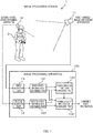
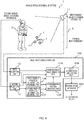
- Fig. 1 illustrates a schematic configuration of an image processing system 1 to be presented as a first embodiment.
- the image processing system 1 includes a first-range-image obtaining apparatus 11, a second-range-image obtaining apparatus 12, and an image processing apparatus 100.
- the first-range-image obtaining apparatus 11 and the second-range-image obtaining apparatus 12 may be referred to collectively as "range-image obtaining apparatus(es)" as appropriate.
- Each of the range-image obtaining apparatuses obtains a range image (depth image, range image data) which is data containing three-dimensional position information (such as distance information (depth information) or distance signals) on a subject (target object).
- the range image contains, for example, pixel information (such as information on gradation and color tone) and distance information obtained on a pixel-by-pixel basis.
- Examples of the range-image obtaining apparatus include a time-of-flight (TOF) camera, a stereo camera, a laser radar (LIDAR: Laser Imaging Detection and Ranging), a millimeter-wave radar, an infrared depth sensor, an ultrasonic sensor, and the like.
- Each range-image obtaining apparatus includes a wired or wireless communication unit (such as a local area network (LAN) interface, a universal serial bus (USB) interface, or a wireless communication module) for communicating with the image processing apparatus 100.
- the range-image obtaining apparatus sends a range image in a compressed format or in an uncompressed format to the image processing apparatus 100 through this communication unit.
- the installation position, imaging direction, imaging area, and the like of the first-range-image obtaining apparatus 11 are set such that the first-range-image obtaining apparatus 11 obtains a range image of a first area covering the whole body (whole) of a person 2 who is the subject and the background behind him or her (hereinafter, referred to as the first range image).
- the installation position, imaging direction, imaging area, and the like of the second-range-image obtaining apparatus 12 are set such that the second-range-image obtaining apparatus 12 obtains a range image of an area of the person 2 smaller than the first area (second area) (hereinafter, referred to as the second range image) .
- the second range image, obtained by the second-range-image obtaining apparatus 12, contains detailed information on a certain body part of the person 2.
- the second-range-image obtaining apparatus 12 is provided at a position close to the person 2 and may be provided, for example, on an item the person 2 is wearing (such as a helmet).
- the image processing apparatus 100 is configured using an information processing apparatus and, for example, performs various kinds of image processing on the range images inputted from the range-image obtaining apparatuses, obtains information on the parts of the subject (such as the skeleton, joints, and outline) (hereinafter, referred to as the part information) contained in the range images sent from the range-image obtaining apparatuses, and generates combined part information which is information combining the part information obtained from the first range image and the part information obtained from the second range image.
- the part information information on the parts of the subject (such as the skeleton, joints, and outline)
- FIG. 2 illustrates an example of the information processing apparatus for configuring the image processing apparatus 100.
- an information processing apparatus 50 includes a processor 51, a main storage device 52, an auxiliary storage device 53, an input device 54, an output device 55, and a communication device 56. These are communicatively coupled to each other through a communication component such as a bus.
- the processor 51 is configured using, for example, a central processing unit (CPU), a micro processing unit (MPU), a graphics processing unit (GPU), a digital signal processor (DSP), or the like is used.
- the processor 51 implements all or some of the functions of the image processing apparatus 100 by reading and executing a program stored in the main storage device 52.
- the main storage device 52 is, for example, a read only memory (ROM), a random access memory (RAM), a non-volatile semiconductor memory (non-volatile RAM (NVRAM)), or the like and stores programs and data.
- the auxiliary storage device 53 is, for example, a hard disk drive, a solid state drive (SSD), an optical storage device (such as a compact disc (CD) or a digital versatile disc (DVD)), a storage system, a device for reading and writing a record medium such as an IC card, an SD memory card, or an optical record medium, or the like.
- Programs and data stored in the auxiliary storage device 53 are loaded to the main storage device 52 as needed.
- the auxiliary storage device 53 may be configured independently of the image processing apparatus 100 like a network storage, for example.
- the input device 54 is a user interface that receives external inputs and is, for example, a keyboard, a mouse, a touchscreen, and/or the like.
- the output device 55 is a user interface that outputs various kinds of information such as the courses of processes and the results of processes and is, for example, an image display device (such as a liquid crystal monitor, a liquid crystal display (LCD), and a graphics card), a printing device, and/or the like.
- the image processing apparatus 100 may be configured to, for example, receive external inputs through the communication device 56.
- the image processing apparatus 100 may be configured to, for example, output various kinds of information such as the courses of process and the results of processes through the communication device 56.
- the communication device 56 is a wired or wireless communication interface that enables communication with other apparatuses and devices and is, for example, a network interface card (NIC), a wireless communication module, or the like.
- NIC network interface card
- the image processing apparatus 100 includes functions of a first reception part 13, a first-part-information obtaining part 101, a second reception part 14, a second-part-information obtaining part 102, a transformation-function generation part 103, and a combined-part-information generation part 104. These functions are implemented by, for example, causing the processor 51 of the image processing apparatus 100 to read and execute a program stored in the main storage device 52 or the auxiliary storage device 53. Also, these functions are implemented by, for example, hardware included in the image processing apparatus 100 (such as a field-programmable gate array (FPGA) or an application specific integrated circuit (ASIC)). Note that besides these functions, the image processing apparatus 100 may include, for example, an operating system, device drivers, a database management system (DBMS), and so on.
- DBMS database management system
- the first reception part 13 receives the first range image, which is sent from the first-range-image obtaining apparatus 11.
- the second reception part 14 receives the second range image, which is sent from the second-range-image obtaining apparatus 12. Note that the first reception part 13 and the second reception part 14 may be configured independently of the image processing apparatus 100.
- the first-part-information obtaining part 101 obtains part information on the person 2 from the first range image obtained by the first-range-image obtaining apparatus 11, and generates first part information containing the obtained content.
- the first-part-information obtaining part 101 obtains the first part information through, for example, skeleton detection, outline detection, joint detection, and the like.
- the first part information contains information indicating the positions of parts represented in a first coordinate system.
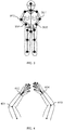
- Fig. 3 illustrates an example (illustrative diagram) of the first part information. As illustrated in Fig. 3 , this first part information contains skeleton information on the whole (whole body) of the person 2.
- the second-part-information obtaining part 102 obtains part information on the person 2 from the second range image obtained by the second-range-image obtaining apparatus 12, and generates second part information containing the obtained content.
- the second-part-information obtaining part 102 obtains the second part information through, for example, skeleton detection, outline detection, joint detection, and the like.
- the second part information contains information indicating the positions of parts represented in a second coordinate system.
- Fig. 4 illustrates an example (illustrative diagram) of the second part information.
- the exemplarily illustrated second part information contains skeleton information on the arms to the fingertips of the person 2.
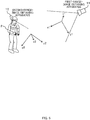
- the transformation-function generation part 103 finds a transformation function based on the first part information and the second part information, the transformation function being a function that performs coordinate transformation between the three-dimensional first coordinate system in the first part information and the three-dimensional second coordinate system in the second part information.
- the transformation-function generation part 103 first identifies the correspondence between the parts contained in the first part information and the parts contained in the second part information. That is, the transformation-function generation part 103 identifies that certain one of the parts contained in the first part information and certain one of the parts contained in the second part information are the same part of the same person. For example, based on the first part information and the second part information, the transformation-function generation part 103 identifies the correspondence between joint parts 301 to 304 in Fig. 3 and joint parts 401 and 404 in Fig. 4 , that is, identifies that these joint parts are the same parts of the same person.
- examples of the method of the above identification include a method based on iterative closest point (ICP), a method utilizing characteristic points, and the like.
- the transformation-function generation part 103 finds a transformation function by using the identified parts as a reference, the transformation function being a function that performs coordinate transformation between the first coordinate system and the second coordinate system.
- the transformation function is a function that converts positional coordinates represented in the second coordinate system (x2, y2, z2) into positional coordinates in the first coordinate system (x1, y1, z1).
- the joint part 301 (x1a, y1a, z1a), the joint part 302 (x1b, y1b, z1b), the joint part 303 (x1c, y1c, z1c), and the joint part 304 (x1d, y1d, z1d) in Fig. 3 are determined to correspond to the joint part 401 (x2a, y2a, z2a), the joint part 402 (x2b, y2b, z2b), the joint part 403 (x2c, y2c, z2c), and the joint part 404 (x2d, y2d, z2d) in Fig.
- the transformation-function generation part 103 finds, as the transformation function, a function F(x, y, z) that satisfies the following.
- the combined-part-information generation part 104 combines the first part information and the second part information by using the transformation function found by the transformation-function generation part 103 to generate combined part information which is information indicating the first part information and the second part information in the common coordinate system.
- the coordinate system in the combined part information may be any one of the first coordinate system and the second coordinate system.
- Fig. 6 illustrates combined part information (illustrative diagram) obtained by combining the first part information illustrated in Fig. 3 (skeleton information on the whole (whole body) of the person 2) and the second part information illustrated in Fig. 4 (skeleton information on the arms to the fingertips of the person 2).
- the combined-part-information generation part 104 generates the combined part information illustrated in Fig. 6 by coupling (jointing) the joint part 301 and the joint part 302 in Fig. 3 (first part information) and the joint part 401 and the joint part 402 in Fig. 4 (second part information) to each other and further coupling (jointing) the joint part 303 and the joint part 304 in Fig. 3 (first part information) and the joint part 403 and the joint part 404 in Fig. 4 (second part information) to each other.
- the image processing apparatus 100 for example, generates time-series combined part information, which contains information indicating a motion of the person 2, based on time-series first range images and time-series second range images sequentially inputted from the first-range-image obtaining apparatus 11 and the second-range-image obtaining apparatus 12 respectively.
- the combined part information cannot be generated in a case where the number of corresponding parts contained in the first part information and the second part information is not enough to generate the combined part information (not enough to generate the transformation function) .
- the combined-part-information generation part 104 for example, generates combined part information by using one of the first part information and the second part information. In this way, the image processing apparatus 100 can always output combined part information. Note that, in this case, the image processing apparatus 100 may preferentially output one of the first part information and the second part information.
- the image processing system 1 in this embodiment can generate information containing both of the information contained in the first range image, obtained by the first-range-image obtaining apparatus 11, and the information contained in the second range image, obtained by the second-range-image obtaining apparatus 12, as a single piece of combined part information.
- both of third-person perspective skeleton information on a motion of the whole body of the person 2 and first-person perspective skeleton information on a small motion of the hands and the fingers of the person 2 can be provided at the same time as a single piece of data represented in a common coordinate system.
- each range-image obtaining apparatus the role of each range-image obtaining apparatus is limited (the first-range-image obtaining apparatus 11 only obtains information on a motion of the whole body of the person 2, whereas the second-range-image obtaining apparatus 12 only obtains information on a small motion of the hands and the fingers of the person 2).
- neither of the range-image obtaining apparatuses necessarily has to be a high-performance apparatus (such as one with high resolution or one with a wide angle of view), which makes it possible to provide the image processing system 1 at low cost.
- neither of the range-image obtaining apparatuses is required to have high resolution, the amount of information processed by the image processing system 1 is reduced, which makes it possible to reduce the processing load and increase the processing speed.
- the installation states (installation position, imaging direction, and imaging area) of the first-range-image obtaining apparatus 11 and the second-range-image obtaining apparatus 12 are not necessarily limited to the states described above.
- both or one of the first-range-image obtaining apparatus 11 and the second-range-image obtaining apparatus 12 may be installed on a mobile object.
- the roles of the first-range-image obtaining apparatus 11 and the second-range-image obtaining apparatus 12 may be switched by time of day.
- the second-range-image obtaining apparatus 12 obtains information on a small motion of the hands of the person 2.
- the second-range-image obtaining apparatus 12 may obtain information on a small motion of other parts of the person 2, such for example as his or her feet.
- the image processing system 1 in this embodiment is therefore widely applicable to various situations.
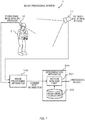
- Fig. 7 illustrates the configuration of an image processing system 1 to be presented as a second embodiment.
- the image processing system 1 in the second embodiment includes a configuration similar to that of the image processing system 1 in the first embodiment and further includes a determination apparatus 200 that identifies a motion of a person 2 and determines whether or not the motion of the person 2 is normal, based on combined part information outputted from the image processing apparatus 100.
- the determination apparatus 200 is configured using, for example, hardware similar to that of the information processing apparatus 50, illustrated in Fig. 2 . Note that the determination apparatus 200 may be configured as a part of the image processing apparatus 100.
- the other components of the image processing system 1 in the second embodiment are similar to those of the image processing system 1 in the first embodiment.
- the determination apparatus 200 includes functions of a motion analysis part 201 and a motion-model storage part 202. These functions are implemented by, for example, causing the processor of the determination apparatus 200 to read and execute a program stored in the main storage device or the auxiliary storage device of the determination apparatus 200. Also, these functions are implemented by, for example, hardware included in the determination apparatus 200 (such as an FPGA or an ASIC) . Note that besides these functions, the determination apparatus 200 may include, for example, an operating system, device drivers, a DBMS, and so on.
- the motion-model storage part 202 stores motion models each of which is information indicating a motion of a person as time-series part information.
- Combined part information generated by the image processing apparatus 100 is inputted into the motion analysis part 201.
- the motion analysis part 201 Based on the combined part information, inputted from the image processing apparatus 100, and the motion models, stored in the motion-model storage part 202, the motion analysis part 201 identifies the motion of the person 2, determines whether or not the motion of the person 2 is normal, and outputs that result as a processing result.
- the motion-model storage part 202 stores motion models each indicating a motion of a person performing a task as time-series skeleton information. Then, the motion analysis part 201 identifies the task the person 2 is performing by comparing a characteristic amount obtained from the combined part information with each motion model, and outputs the identified result as a processing result.
- the motion-model storage part 202 stores a motion model, generated by machine learning or the like, indicating a motion of a person normally performing a task as time-series skeleton information (hereinafter, referred to as the normal model), and a threshold to be used in determination of whether or not the task being performed by the person 2 is normal based on the normal model.
- the motion analysis part 201 determines whether or not the task being performed by the person 2 is normal based on the normal model and the threshold by comparing a characteristic amount obtained from the combined part information with the normal model, and outputs the result of the determination as a processing result.
- the determination apparatus 200 may output a warning (such as a warning display and/or a warning sound) to the person 2, a person around the person 2, or some other person if the motion analysis part 201 determines that the task being performed by the person 2 is not normal.
- a warning such as a warning display and/or a warning sound
- a motion of the person 2 can be accurately identified and whether or not the motion of the person 2 is normal can be accurately determined based on combined part information, which contains information on a motion of the whole body of the person 2 and information on a small motion of a certain body part of the person 2.
- a task being performed by a worker in a factory or the like (such as by which machine the worker is working and in what posture the worker is working) can be accurately identified.
- whether or not the task being performed by the worker is normal can be accurately determined. For example, information on whether the motion of the worker is deviating from the standard or whether the task is being delayed can be obtained.
- a motion of a care-receiver or patient in a nursing home, hospital, or the like can be accurately identified.
- a motion of the care-receiver or patient for example, his or her action of getting up from a bed, his or her action while eating, or the like
- motions of a customer in a store or the like which customers come in and out of can be accurately identified, thus enabling a detailed analysis on customer behavior (such as what kinds of products they are interested in).
- whether or not a motion of a customer is normal can be accurately determined.
- the above description has presented the case of using two range-image obtaining apparatuses (first-range-image obtaining apparatus 11 and second-range-image obtaining apparatus 12).
- more range-image obtaining apparatuses may be used.
- the combined part information contains information obtained from range images sent from a plurality of range-image obtaining apparatuses differing from each other in installation position, imaging direction, imaging area, and the like.
- the characteristic amount can be set specifically from various perspectives. This makes it possible to accurately identify a motion of the person 2 and accurately determine whether or not the motion of the person 2 is normal.
- Fig. 8 illustrates the configuration of an image processing system 1 to be presented as a third embodiment.
- the image processing system 1 in the third embodiment is based on the configuration of the image processing system 1 in the second embodiment.
- a first-range-image obtaining apparatus 11 of the image processing system 1 in the third embodiment is fixed to an upper end portion of a fixing instrument 3 standing to a predetermined height from the floor surface.
- An image processing apparatus 100 in the third embodiment includes the configuration of the image processing apparatus 100 in the second embodiment and further includes an installation-state-information storage part 105.
- a transformation-function generation part 103 of the image processing apparatus 100 in the third embodiment receives a measurement value (or measurement signal) sent from a three-dimensional sensor 15 attached to a person 2.
- the three-dimensional sensor 15 includes, for example, at least one of a tilt sensor, an acceleration sensor, a gyroscope, and an orientation sensor.
- the three-dimensional sensor 15 obtains information indicating the imaging direction of a second-range-image obtaining apparatus 12 (hereinafter, referred to as the second installation-state information), and sends the above-mentioned measurement value to the image processing apparatus 100.
- the three-dimensional sensor 15 is installed in such a manner that it can measure the state of the second-range-image obtaining apparatus 12.
- the three-dimensional sensor 15 is directly put on the person 2 (for example, attached to a helmet) .
- the other components of the image processing system 1 in the third embodiment are similar to those of the image processing system 1 in the second embodiment.
- the installation-state-information storage part 105 stores information indicating the installation state (such as the height, the imaging direction, and the angle to the horizontal direction) of the first-range-image obtaining apparatus 11, which is installed on the fixing instrument 3 (hereinafter, referred to as the first installation-state information).
- a transformation-function generation part 103 finds the difference between the imaging direction of the first-range-image obtaining apparatus 11 and the imaging direction of the second-range-image obtaining apparatus 12 by comparing the installation-state information stored in the installation-state-information storage part 105 and the information inputted from the three-dimensional sensor 15, and calculates a transformation function by using the value (difference) thus found.
- the image processing system 1 in the third embodiment can efficiently find the transformation function since the information indicating the installation state of a range-image obtaining apparatus has been stored in advance, as described above. Accordingly, the image processing system 1 in the third embodiment can efficiently generate the combined part information.
- the range-image obtaining apparatuses may be provided with, for example, a wide-angle lens or a telephoto lens. This improves the degree of freedom in installation of the range-image obtaining apparatuses.
- the transformation-function generation part 103 generates the transformation function while using the difference in lens magnification as one parameter.
- the second-range-image obtaining apparatus 12 is attached to the person 2.
- the second-range-image obtaining apparatus 12 may also be fixed to a fixing instrument standing to a predetermined height from the floor surface.
- the relative angles of the first-range-image obtaining apparatus 11 and the second-range-image obtaining apparatus 12 are measured in advance to find the transformation function in advance, and this is stored in the installation-state-information storage part 105. In this way, the process of calculating the transformation function by the transformation-function generation part 103 can be omitted. Accordingly, the combined part information can be efficiently generated.
- Fig. 9 illustrates the configuration of an image processing system 1 to be presented as a fourth embodiment.
- its image processing apparatus 100 includes a first reception part 13, a second reception part 14, a first-marker-position-information obtaining part 106, a second-marker-position-information obtaining part 107, a transformation-function generation part 103, a combined-range-image generation part 108, and a part-information generation part 109.
- the configurations of the first reception part 13 and the second reception part 14 are similar to those in the third embodiment.
- the configuration of a determination apparatus 200 of the image processing system 1 in the fourth embodiment is similar to that in the third embodiment.
- a first-range-image obtaining apparatus 11 is fixed to an upper end portion of a fixing instrument 3 standing to a predetermined height from the floor surface.
- the image processing system 1 presented as the fourth embodiment includes one or more markers 7 fixedly installed at predetermined positions around a person 2.
- the first-marker-position-information obtaining part 106 obtains information indicating the positions of the markers 7 in the three-dimensional coordinate system in the first range image (hereinafter, referred to as the first marker-position information).
- the second-marker-position-information obtaining part 107 obtains information indicating the positions of the markers 7 in the three-dimensional coordinate system in the second range image (hereinafter, referred to as the second marker-position information).
- the transformation-function generation part 103 finds a transformation function based on the first marker-position information and the second marker-position information.
- the transformation function is found by identifying the correspondence between the parts (joint parts) contained in the first range image and the parts (joint parts) contained in the second range image.
- the transformation-function generation part 103 finds the transformation function by using, as a reference, the position information on the same markers 7 contained in both of the first range image and the second range image, instead of the position information on the parts (joint parts).
- the fourth embodiment does not need the identification of the correspondence between parts unlike the first embodiment. Accordingly, the transformation-function generation part 103 can efficiently find the transformation function.
- the transformation function is found using body parts (joint parts) of the person 2 as a reference.
- the transformation function is found based on the positions of the markers 7, whose installation positions remain unchanged.
- an accurate transformation function can be found even if the motion of the person 2 is large.
- the accuracy of the transformation function can be further improved by, for example, increasing the number of markers 7 installed and, for example, using the average of the parameters of transformation functions found based on the respective markers 7.
- the combined-range-image generation part 108 generates information combining the first range image inputted from the first reception part 13 and the second range image inputted from the second reception part 14 as data indicating the first range image and the second range image in the common coordinate system (for example, the three-dimensional coordinate system in the first range image or the three-dimensional coordinate system in the second range image) (hereinafter, referred to as the combined range image).
- the combined-range-image generation part 108 may, for example, compare the first range image and the second range image on a pixel-by-pixel basis and preferentially employ pixels with higher resolution (for example, pixels obtained by imaging the person 2 from a closer position) . In this way, it is possible to, for example, generate a combined range image containing both of information on a specific part of the person 2 obtained from the second-range-image obtaining apparatus 12 and information on the whole body of the person 2 obtained from the first-range-image obtaining apparatus 11.
- the range image containing the information on the markers 7 may be employed in the generation of the combined range image. In this way, the image processing apparatus 100 can continue outputting a combined range image even if, for example, the person 2 moves to a position far from the markers 7.
- the part-information generation part 109 detects parts of the person 2 in the combined range image, generates information of the parts of the person 2 (hereinafter, referred to as the part information), and inputs the generated part information to the determination apparatus 200.
- the configuration and the function of the determination apparatus 200 are similar to those of the determination apparatus 200 in the third embodiment.
- the image processing system 1 in the fourth embodiment can find an accurate transformation function by using the positions of the markers 7 as a reference. Moreover, the image processing apparatus 100 (part-information generation part 109) can efficiently generate the part information since it detects the part information from a single combined range image.
- some or all of the above-described components, functional parts, processing parts, processing means, and the like may be implemented with hardware by, for example, designing them with integrated circuits.
- the above-described components, functions, and the like may be implemented with software by causing a processor to interpret and execute a program that implements their functions.
- the information of the program, tables, files, and the like that implement the functions can be stored in a record device such as a memory, a hard disk drive, or a solid state drive (SSD) or in a record medium such as an IC card, an SD card, or a DVD.
- control lines and the information lines represent lines that are considered necessary for description, and do not necessarily represent all control lines and information lines involved in implementation. For example, in practice, almost all components may be considered coupled to each other.
- each above-described image processing system 1 is a mere example.
- the arrangement of the various functional parts, processing parts, and databases is changeable to an arrangement that is optimum in view of the performance, processing efficiency, communication efficiency, and the like of the hardware and software included in the image processing system 1.
- the configuration (such as the schema) of the databases mentioned above is flexibly changeable in view of efficient use of a resource, improvement of processing efficiency, improvement of access efficiency, improvement of search efficiency, and the like.
- a method may be employed in which, for example, a digital still camera, a surveillance camera, or the like is used for each of the range-image obtaining apparatuses, and the distance to the subject and his or her skeleton information are estimated by performing image processing on images obtained by the range-image obtaining apparatuses.
- two-dimensional image signals are the processing target, and therefore the computation load can be kept low.
- the subject may be, for example, an animal or an inanimate object.
Landscapes
- Engineering & Computer Science (AREA)
- Physics & Mathematics (AREA)
- General Physics & Mathematics (AREA)
- Theoretical Computer Science (AREA)
- Computer Vision & Pattern Recognition (AREA)
- Multimedia (AREA)
- Health & Medical Sciences (AREA)
- General Health & Medical Sciences (AREA)
- Human Computer Interaction (AREA)
- Nuclear Medicine, Radiotherapy & Molecular Imaging (AREA)
- Radiology & Medical Imaging (AREA)
- Quality & Reliability (AREA)
- Medical Informatics (AREA)
- Psychiatry (AREA)
- Social Psychology (AREA)
- Image Analysis (AREA)
- Image Processing (AREA)
- Studio Devices (AREA)
Description
- The present invention relates to an image processing apparatus and an image processing method.
- Japanese Patent Application Publication No.
2014-130519 - Japanese Patent Application Publication No.
2014-21816 -
WO 2014/154 839 A1 discloses a high-definition 3D camera device capable of allowing tracking objects at near and far distances as well as tracking at the same time large and small objects. - Furthermore, Non-Patent Literature: Ha Yeonmin et al., "3D registration of multi-view depth data for hand-arm pose estimation", discloses an outlier rejection method, which uses skeletal consistency, is capable of reducing the computation time of a 3D registration process without a loss of robustness.
- In recent years, range image sensors have been actively applied to various fields. Range image sensors are capable of obtaining three-dimensional position information in real time, and attempts have been made to use them in human behavior analysis . Here, in human behavior analysis using range images, there is a need for simultaneously figuring out information on a motion of the whole body of the subject (like a motion in a bird's eye view), such as where the person is or moves (wholeness), and information on a small motion of a certain part of the subject, such as what task is being performed with the hands or feet of the person. However, neither of
Patent Literature 1 andPatent Literature 2 mentioned above discloses a configuration taking such a need into consideration. - An object of the present invention is to provide an image processing apparatus according to
claim 1 and an image processing method according to claim 6 capable of simultaneously figuring out information on a motion of the whole body of a subject and information on a small motion of a certain part of the subject by using range images obtained by imaging the subject. - An aspect of the present invention is an image processing apparatus including a first-part-information obtaining part configured to obtain first part information from a first range image obtained by imaging a first area of a subject, the first part information being information on a part of the subject, a second-part-information obtaining part configured to obtain second part information from a second range image obtained by imaging a second area of the subject smaller than the first area, the second part information being information on a part of the subject, a transformation-function generation part configured to find a transformation function based on the first part information and the second part information, the transformation function being a function that performs coordinate transformation between a first coordinate system in the first part information and a second coordinate system in the second part information, and a combined-part-information generation part configured to generate combined part information based on the transformation function, the combined part information being information representing the first part information and the second part information in a common coordinate system.
- Other problems disclosed by the present application and solutions thereto will be apparent from the section of the description of embodiments and the drawings.
- According to the present invention, it is possible to simultaneously figure out information on a motion of the whole body of a subject and information on a small motion of a certain part of the subject by using range images obtained by imaging the subject. The description is defined by the appended claims.
-
-
Fig. 1 is a diagram illustrating the configuration of an image processing system in a first embodiment. -
Fig. 2 illustrates an example of an information processing apparatus for configuring an image processing apparatus and a determination apparatus. -
Fig. 3 is a diagram explaining first part information. -
Fig. 4 is a diagram explaining second part information. -
Fig. 5 is a diagram explaining how to find a transformation function. -
Fig. 6 is a diagram explaining combined part information. 210582EP -
Fig. 7 is a diagram illustrating the configuration of an image processing system in a second embodiment. -
Fig. 8 is a diagram illustrating the configuration of an image processing system in a third embodiment. -
Fig. 9 is a diagram illustrating the configuration of an image processing system in a fourth embodiment. - Embodiments will be described below. In the following description, identical or like components are denoted by identical reference signs, and redundant description thereof may be omitted.
-
Fig. 1 illustrates a schematic configuration of animage processing system 1 to be presented as a first embodiment. As illustrated inFig. 1 , theimage processing system 1 includes a first-range-image obtaining apparatus 11, a second-range-image obtaining apparatus 12, and animage processing apparatus 100. Note that in the following description, the first-range-image obtaining apparatus 11 and the second-range-image obtaining apparatus 12 may be referred to collectively as "range-image obtaining apparatus(es)" as appropriate. - Each of the range-image obtaining apparatuses obtains a range image (depth image, range image data) which is data containing three-dimensional position information (such as distance information (depth information) or distance signals) on a subject (target object). The range image contains, for example, pixel information (such as information on gradation and color tone) and distance information obtained on a pixel-by-pixel basis. Examples of the range-image obtaining apparatus include a time-of-flight (TOF) camera, a stereo camera, a laser radar (LIDAR: Laser Imaging Detection and Ranging), a millimeter-wave radar, an infrared depth sensor, an ultrasonic sensor, and the like.
- Each range-image obtaining apparatus includes a wired or wireless communication unit (such as a local area network (LAN) interface, a universal serial bus (USB) interface, or a wireless communication module) for communicating with the
image processing apparatus 100. The range-image obtaining apparatus sends a range image in a compressed format or in an uncompressed format to theimage processing apparatus 100 through this communication unit. - As illustrated in
Fig. 1 , the installation position, imaging direction, imaging area, and the like of the first-range-image obtaining apparatus 11 are set such that the first-range-image obtaining apparatus 11 obtains a range image of a first area covering the whole body (whole) of aperson 2 who is the subject and the background behind him or her (hereinafter, referred to as the first range image). On the other hand, the installation position, imaging direction, imaging area, and the like of the second-range-image obtaining apparatus 12 are set such that the second-range-image obtaining apparatus 12 obtains a range image of an area of theperson 2 smaller than the first area (second area) (hereinafter, referred to as the second range image) . The second range image, obtained by the second-range-image obtaining apparatus 12, contains detailed information on a certain body part of theperson 2. The second-range-image obtaining apparatus 12 is provided at a position close to theperson 2 and may be provided, for example, on an item theperson 2 is wearing (such as a helmet). - The
image processing apparatus 100 is configured using an information processing apparatus and, for example, performs various kinds of image processing on the range images inputted from the range-image obtaining apparatuses, obtains information on the parts of the subject (such as the skeleton, joints, and outline) (hereinafter, referred to as the part information) contained in the range images sent from the range-image obtaining apparatuses, and generates combined part information which is information combining the part information obtained from the first range image and the part information obtained from the second range image. -
Fig. 2 illustrates an example of the information processing apparatus for configuring theimage processing apparatus 100. As illustrated inFig. 2 , aninformation processing apparatus 50 includes aprocessor 51, amain storage device 52, anauxiliary storage device 53, aninput device 54, anoutput device 55, and acommunication device 56. These are communicatively coupled to each other through a communication component such as a bus. - The
processor 51 is configured using, for example, a central processing unit (CPU), a micro processing unit (MPU), a graphics processing unit (GPU), a digital signal processor (DSP), or the like is used. Theprocessor 51 implements all or some of the functions of theimage processing apparatus 100 by reading and executing a program stored in themain storage device 52. Themain storage device 52 is, for example, a read only memory (ROM), a random access memory (RAM), a non-volatile semiconductor memory (non-volatile RAM (NVRAM)), or the like and stores programs and data. - The
auxiliary storage device 53 is, for example, a hard disk drive, a solid state drive (SSD), an optical storage device (such as a compact disc (CD) or a digital versatile disc (DVD)), a storage system, a device for reading and writing a record medium such as an IC card, an SD memory card, or an optical record medium, or the like. Programs and data stored in theauxiliary storage device 53 are loaded to themain storage device 52 as needed. Theauxiliary storage device 53 may be configured independently of theimage processing apparatus 100 like a network storage, for example. - The
input device 54 is a user interface that receives external inputs and is, for example, a keyboard, a mouse, a touchscreen, and/or the like. Theoutput device 55 is a user interface that outputs various kinds of information such as the courses of processes and the results of processes and is, for example, an image display device (such as a liquid crystal monitor, a liquid crystal display (LCD), and a graphics card), a printing device, and/or the like. Note that theimage processing apparatus 100 may be configured to, for example, receive external inputs through thecommunication device 56. Also, theimage processing apparatus 100 may be configured to, for example, output various kinds of information such as the courses of process and the results of processes through thecommunication device 56. - The
communication device 56 is a wired or wireless communication interface that enables communication with other apparatuses and devices and is, for example, a network interface card (NIC), a wireless communication module, or the like. - As illustrated in
Fig. 1 , theimage processing apparatus 100 includes functions of afirst reception part 13, a first-part-information obtaining part 101, asecond reception part 14, a second-part-information obtaining part 102, a transformation-function generation part 103, and a combined-part-information generation part 104. These functions are implemented by, for example, causing theprocessor 51 of theimage processing apparatus 100 to read and execute a program stored in themain storage device 52 or theauxiliary storage device 53. Also, these functions are implemented by, for example, hardware included in the image processing apparatus 100 (such as a field-programmable gate array (FPGA) or an application specific integrated circuit (ASIC)). Note that besides these functions, theimage processing apparatus 100 may include, for example, an operating system, device drivers, a database management system (DBMS), and so on. - Among the functions listed above, the
first reception part 13 receives the first range image, which is sent from the first-range-image obtaining apparatus 11. Thesecond reception part 14 receives the second range image, which is sent from the second-range-image obtaining apparatus 12. Note that thefirst reception part 13 and thesecond reception part 14 may be configured independently of theimage processing apparatus 100. - The first-part-
information obtaining part 101 obtains part information on theperson 2 from the first range image obtained by the first-range-image obtaining apparatus 11, and generates first part information containing the obtained content. The first-part-information obtaining part 101 obtains the first part information through, for example, skeleton detection, outline detection, joint detection, and the like. The first part information contains information indicating the positions of parts represented in a first coordinate system. -
Fig. 3 illustrates an example (illustrative diagram) of the first part information. As illustrated inFig. 3 , this first part information contains skeleton information on the whole (whole body) of theperson 2. - The second-part-
information obtaining part 102 obtains part information on theperson 2 from the second range image obtained by the second-range-image obtaining apparatus 12, and generates second part information containing the obtained content. The second-part-information obtaining part 102 obtains the second part information through, for example, skeleton detection, outline detection, joint detection, and the like. The second part information contains information indicating the positions of parts represented in a second coordinate system. -
Fig. 4 illustrates an example (illustrative diagram) of the second part information. As illustrated inFig. 4 , the exemplarily illustrated second part information contains skeleton information on the arms to the fingertips of theperson 2. - The transformation-
function generation part 103 finds a transformation function based on the first part information and the second part information, the transformation function being a function that performs coordinate transformation between the three-dimensional first coordinate system in the first part information and the three-dimensional second coordinate system in the second part information. - More specifically, the transformation-
function generation part 103 first identifies the correspondence between the parts contained in the first part information and the parts contained in the second part information. That is, the transformation-function generation part 103 identifies that certain one of the parts contained in the first part information and certain one of the parts contained in the second part information are the same part of the same person. For example, based on the first part information and the second part information, the transformation-function generation part 103 identifies the correspondence betweenjoint parts 301 to 304 inFig. 3 andjoint parts Fig. 4 , that is, identifies that these joint parts are the same parts of the same person. Here, examples of the method of the above identification include a method based on iterative closest point (ICP), a method utilizing characteristic points, and the like. The transformation-function generation part 103 then finds a transformation function by using the identified parts as a reference, the transformation function being a function that performs coordinate transformation between the first coordinate system and the second coordinate system. - How to find the transformation function will be described with reference to
Fig. 5 . As illustrated inFig. 5 , the parts contained in the first range image, obtained by the first-range-image obtaining apparatus 11, are represented in the first coordinate system (x1, y1, z1), whereas the parts contained in the second range image, obtained by the second-range-image obtaining apparatus 12, are represented in the second coordinate system (x2, y2, z2). In this case, the transformation function is a function that converts positional coordinates represented in the second coordinate system (x2, y2, z2) into positional coordinates in the first coordinate system (x1, y1, z1). Here, assume for example that the joint part 301 (x1a, y1a, z1a), the joint part 302 (x1b, y1b, z1b), the joint part 303 (x1c, y1c, z1c), and the joint part 304 (x1d, y1d, z1d) inFig. 3 are determined to correspond to the joint part 401 (x2a, y2a, z2a), the joint part 402 (x2b, y2b, z2b), the joint part 403 (x2c, y2c, z2c), and the joint part 404 (x2d, y2d, z2d) inFig. 4 respectively (thejoint part 301 corresponds to thejoint part 401, thejoint part 302 corresponds to thejoint part 402, thejoint part 303 corresponds to thejoint part 403, and thejoint part 304 corresponds to the joint part 404) . In this case, the transformation-function generation part 103 finds, as the transformation function, a function F(x, y, z) that satisfies the following.
(x1a, y1a, z1a) = F(x2a, y2a, z2a)
(x1b, y1b, z1b) = F(x2b, y2b, z2b)
(x1c, y1c, z1c) = F(x2c, y2c, z2c)
(x1d, y1d, z1d) = F(x2d, y2d, z2d) - Referring back to
Fig. 1 , the combined-part-information generation part 104 combines the first part information and the second part information by using the transformation function found by the transformation-function generation part 103 to generate combined part information which is information indicating the first part information and the second part information in the common coordinate system. Note that while the above function F (x, y, z) converts the second coordinate system into the first coordinate system, the coordinate system in the combined part information may be any one of the first coordinate system and the second coordinate system. -
Fig. 6 illustrates combined part information (illustrative diagram) obtained by combining the first part information illustrated inFig. 3 (skeleton information on the whole (whole body) of the person 2) and the second part information illustrated inFig. 4 (skeleton information on the arms to the fingertips of the person 2). The combined-part-information generation part 104 generates the combined part information illustrated inFig. 6 by coupling (jointing) thejoint part 301 and thejoint part 302 inFig. 3 (first part information) and thejoint part 401 and thejoint part 402 inFig. 4 (second part information) to each other and further coupling (jointing) thejoint part 303 and thejoint part 304 inFig. 3 (first part information) and thejoint part 403 and thejoint part 404 inFig. 4 (second part information) to each other. - The
image processing apparatus 100, for example, generates time-series combined part information, which contains information indicating a motion of theperson 2, based on time-series first range images and time-series second range images sequentially inputted from the first-range-image obtaining apparatus 11 and the second-range-image obtaining apparatus 12 respectively. - Note that the combined part information cannot be generated in a case where the number of corresponding parts contained in the first part information and the second part information is not enough to generate the combined part information (not enough to generate the transformation function) . In this case, the combined-part-
information generation part 104, for example, generates combined part information by using one of the first part information and the second part information. In this way, theimage processing apparatus 100 can always output combined part information. Note that, in this case, theimage processing apparatus 100 may preferentially output one of the first part information and the second part information. - As described above, the
image processing system 1 in this embodiment can generate information containing both of the information contained in the first range image, obtained by the first-range-image obtaining apparatus 11, and the information contained in the second range image, obtained by the second-range-image obtaining apparatus 12, as a single piece of combined part information. Hence, both of third-person perspective skeleton information on a motion of the whole body of theperson 2 and first-person perspective skeleton information on a small motion of the hands and the fingers of theperson 2 can be provided at the same time as a single piece of data represented in a common coordinate system. In this way, it is possible to simultaneously figure out, for example, information on a motion of the whole body of the person 2 (like his or her motion in a bird's eye view), such as where theperson 2 is and where he or she moves to (wholeness), and information on a small motion of a certain body part of theperson 2, such as what task is being performed with the hands or feet of theperson 2. - Moreover, in the
image processing system 1 in this embodiment, the role of each range-image obtaining apparatus is limited (the first-range-image obtaining apparatus 11 only obtains information on a motion of the whole body of theperson 2, whereas the second-range-image obtaining apparatus 12 only obtains information on a small motion of the hands and the fingers of the person 2). Thus, neither of the range-image obtaining apparatuses necessarily has to be a high-performance apparatus (such as one with high resolution or one with a wide angle of view), which makes it possible to provide theimage processing system 1 at low cost. In addition, since neither of the range-image obtaining apparatuses is required to have high resolution, the amount of information processed by theimage processing system 1 is reduced, which makes it possible to reduce the processing load and increase the processing speed. - It is to be noted that the installation states (installation position, imaging direction, and imaging area) of the first-range-
image obtaining apparatus 11 and the second-range-image obtaining apparatus 12 are not necessarily limited to the states described above. For example, both or one of the first-range-image obtaining apparatus 11 and the second-range-image obtaining apparatus 12 may be installed on a mobile object. Also, the roles of the first-range-image obtaining apparatus 11 and the second-range-image obtaining apparatus 12 may be switched by time of day. - Moreover, the above description has taken the example where the second-range-
image obtaining apparatus 12 obtains information on a small motion of the hands of theperson 2. However, the second-range-image obtaining apparatus 12 may obtain information on a small motion of other parts of theperson 2, such for example as his or her feet. Theimage processing system 1 in this embodiment is therefore widely applicable to various situations. -
Fig. 7 illustrates the configuration of animage processing system 1 to be presented as a second embodiment. Theimage processing system 1 in the second embodiment includes a configuration similar to that of theimage processing system 1 in the first embodiment and further includes adetermination apparatus 200 that identifies a motion of aperson 2 and determines whether or not the motion of theperson 2 is normal, based on combined part information outputted from theimage processing apparatus 100. Thedetermination apparatus 200 is configured using, for example, hardware similar to that of theinformation processing apparatus 50, illustrated inFig. 2 . Note that thedetermination apparatus 200 may be configured as a part of theimage processing apparatus 100. The other components of theimage processing system 1 in the second embodiment are similar to those of theimage processing system 1 in the first embodiment. - As illustrated in
Fig. 7 , thedetermination apparatus 200 includes functions of amotion analysis part 201 and a motion-model storage part 202. These functions are implemented by, for example, causing the processor of thedetermination apparatus 200 to read and execute a program stored in the main storage device or the auxiliary storage device of thedetermination apparatus 200. Also, these functions are implemented by, for example, hardware included in the determination apparatus 200 (such as an FPGA or an ASIC) . Note that besides these functions, thedetermination apparatus 200 may include, for example, an operating system, device drivers, a DBMS, and so on. - Among the functions listed above, the motion-
model storage part 202 stores motion models each of which is information indicating a motion of a person as time-series part information. - Combined part information generated by the
image processing apparatus 100 is inputted into themotion analysis part 201. Based on the combined part information, inputted from theimage processing apparatus 100, and the motion models, stored in the motion-model storage part 202, themotion analysis part 201 identifies the motion of theperson 2, determines whether or not the motion of theperson 2 is normal, and outputs that result as a processing result. - The motion-
model storage part 202, for example, stores motion models each indicating a motion of a person performing a task as time-series skeleton information. Then, themotion analysis part 201 identifies the task theperson 2 is performing by comparing a characteristic amount obtained from the combined part information with each motion model, and outputs the identified result as a processing result. - Also, the motion-
model storage part 202, for example, stores a motion model, generated by machine learning or the like, indicating a motion of a person normally performing a task as time-series skeleton information (hereinafter, referred to as the normal model), and a threshold to be used in determination of whether or not the task being performed by theperson 2 is normal based on the normal model. Themotion analysis part 201 then determines whether or not the task being performed by theperson 2 is normal based on the normal model and the threshold by comparing a characteristic amount obtained from the combined part information with the normal model, and outputs the result of the determination as a processing result. Meanwhile, thedetermination apparatus 200 may output a warning (such as a warning display and/or a warning sound) to theperson 2, a person around theperson 2, or some other person if themotion analysis part 201 determines that the task being performed by theperson 2 is not normal. - With the
image processing system 1 in the second embodiment, a motion of theperson 2 can be accurately identified and whether or not the motion of theperson 2 is normal can be accurately determined based on combined part information, which contains information on a motion of the whole body of theperson 2 and information on a small motion of a certain body part of theperson 2. For example, a task being performed by a worker in a factory or the like (such as by which machine the worker is working and in what posture the worker is working) can be accurately identified. Also, for example, whether or not the task being performed by the worker is normal (such as whether or not the worker is performing a dangerous action) can be accurately determined. For example, information on whether the motion of the worker is deviating from the standard or whether the task is being delayed can be obtained. Also, for example, a motion of a care-receiver or patient in a nursing home, hospital, or the like can be accurately identified. Moreover, for example, whether or not a motion of the care-receiver or patient (for example, his or her action of getting up from a bed, his or her action while eating, or the like) is normal can be accurately determined. Also, for example, motions of a customer in a store or the like which customers come in and out of can be accurately identified, thus enabling a detailed analysis on customer behavior (such as what kinds of products they are interested in). Moreover, for example, whether or not a motion of a customer is normal (such as whether his or her behavior is suspicious) can be accurately determined. - Meanwhile, the above description has presented the case of using two range-image obtaining apparatuses (first-range-
image obtaining apparatus 11 and second-range-image obtaining apparatus 12). However, more range-image obtaining apparatuses may be used. For example, by imaging theperson 2 from a plurality of directions (for example, from front and behind), it is possible to more accurately figure out motion of theperson 2 and more accurately determine whether or not the motion of theperson 2 is normal. Also, in this case, the combined part information contains information obtained from range images sent from a plurality of range-image obtaining apparatuses differing from each other in installation position, imaging direction, imaging area, and the like. Hence, the characteristic amount can be set specifically from various perspectives. This makes it possible to accurately identify a motion of theperson 2 and accurately determine whether or not the motion of theperson 2 is normal. -
Fig. 8 illustrates the configuration of animage processing system 1 to be presented as a third embodiment. Theimage processing system 1 in the third embodiment is based on the configuration of theimage processing system 1 in the second embodiment. A first-range-image obtaining apparatus 11 of theimage processing system 1 in the third embodiment is fixed to an upper end portion of a fixinginstrument 3 standing to a predetermined height from the floor surface. Animage processing apparatus 100 in the third embodiment includes the configuration of theimage processing apparatus 100 in the second embodiment and further includes an installation-state-information storage part 105. Also, a transformation-function generation part 103 of theimage processing apparatus 100 in the third embodiment receives a measurement value (or measurement signal) sent from a three-dimensional sensor 15 attached to aperson 2. The three-dimensional sensor 15 includes, for example, at least one of a tilt sensor, an acceleration sensor, a gyroscope, and an orientation sensor. The three-dimensional sensor 15 obtains information indicating the imaging direction of a second-range-image obtaining apparatus 12 (hereinafter, referred to as the second installation-state information), and sends the above-mentioned measurement value to theimage processing apparatus 100. The three-dimensional sensor 15 is installed in such a manner that it can measure the state of the second-range-image obtaining apparatus 12. For example, the three-dimensional sensor 15 is directly put on the person 2 (for example, attached to a helmet) . Note that the other components of theimage processing system 1 in the third embodiment are similar to those of theimage processing system 1 in the second embodiment. - The installation-state-
information storage part 105 stores information indicating the installation state (such as the height, the imaging direction, and the angle to the horizontal direction) of the first-range-image obtaining apparatus 11, which is installed on the fixing instrument 3 (hereinafter, referred to as the first installation-state information). - A transformation-
function generation part 103, for example, finds the difference between the imaging direction of the first-range-image obtaining apparatus 11 and the imaging direction of the second-range-image obtaining apparatus 12 by comparing the installation-state information stored in the installation-state-information storage part 105 and the information inputted from the three-dimensional sensor 15, and calculates a transformation function by using the value (difference) thus found. - The
image processing system 1 in the third embodiment can efficiently find the transformation function since the information indicating the installation state of a range-image obtaining apparatus has been stored in advance, as described above. Accordingly, theimage processing system 1 in the third embodiment can efficiently generate the combined part information. - Meanwhile, the range-image obtaining apparatuses may be provided with, for example, a wide-angle lens or a telephoto lens. This improves the degree of freedom in installation of the range-image obtaining apparatuses. Note that in this case, the transformation-
function generation part 103 generates the transformation function while using the difference in lens magnification as one parameter. - In the above description, the second-range-
image obtaining apparatus 12 is attached to theperson 2. However, as in the first-range-image obtaining apparatus 11, the second-range-image obtaining apparatus 12 may also be fixed to a fixing instrument standing to a predetermined height from the floor surface. In this case, for example, the relative angles of the first-range-image obtaining apparatus 11 and the second-range-image obtaining apparatus 12 are measured in advance to find the transformation function in advance, and this is stored in the installation-state-information storage part 105. In this way, the process of calculating the transformation function by the transformation-function generation part 103 can be omitted. Accordingly, the combined part information can be efficiently generated. -
Fig. 9 illustrates the configuration of animage processing system 1 to be presented as a fourth embodiment. In theimage processing system 1 in the fourth embodiment, itsimage processing apparatus 100 includes afirst reception part 13, asecond reception part 14, a first-marker-position-information obtaining part 106, a second-marker-position-information obtaining part 107, a transformation-function generation part 103, a combined-range-image generation part 108, and a part-information generation part 109. Among these, the configurations of thefirst reception part 13 and thesecond reception part 14 are similar to those in the third embodiment. Moreover, the configuration of adetermination apparatus 200 of theimage processing system 1 in the fourth embodiment is similar to that in the third embodiment. Furthermore, as in the third embodiment, a first-range-image obtaining apparatus 11 is fixed to an upper end portion of a fixinginstrument 3 standing to a predetermined height from the floor surface. Theimage processing system 1 presented as the fourth embodiment includes one ormore markers 7 fixedly installed at predetermined positions around aperson 2. - From a first range image obtained by the first-range-
image obtaining apparatus 11, the first-marker-position-information obtaining part 106 obtains information indicating the positions of themarkers 7 in the three-dimensional coordinate system in the first range image (hereinafter, referred to as the first marker-position information). - From a second range image obtained by a second-range-
image obtaining apparatus 12, the second-marker-position-information obtaining part 107 obtains information indicating the positions of themarkers 7 in the three-dimensional coordinate system in the second range image (hereinafter, referred to as the second marker-position information). - The transformation-
function generation part 103 finds a transformation function based on the first marker-position information and the second marker-position information. Here, in the first embodiment, the transformation function is found by identifying the correspondence between the parts (joint parts) contained in the first range image and the parts (joint parts) contained in the second range image. However, in the fourth embodiment, the transformation-function generation part 103 finds the transformation function by using, as a reference, the position information on thesame markers 7 contained in both of the first range image and the second range image, instead of the position information on the parts (joint parts). Hence, the fourth embodiment does not need the identification of the correspondence between parts unlike the first embodiment. Accordingly, the transformation-function generation part 103 can efficiently find the transformation function. - Here, in the first embodiment, the transformation function is found using body parts (joint parts) of the
person 2 as a reference. Thus, errors will be large if the motion of theperson 2 is large. However, in the fourth embodiment, the transformation function is found based on the positions of themarkers 7, whose installation positions remain unchanged. Thus, an accurate transformation function can be found even if the motion of theperson 2 is large. Note that the accuracy of the transformation function can be further improved by, for example, increasing the number ofmarkers 7 installed and, for example, using the average of the parameters of transformation functions found based on therespective markers 7. - By using the transformation function thus found, the combined-range-
image generation part 108 generates information combining the first range image inputted from thefirst reception part 13 and the second range image inputted from thesecond reception part 14 as data indicating the first range image and the second range image in the common coordinate system (for example, the three-dimensional coordinate system in the first range image or the three-dimensional coordinate system in the second range image) (hereinafter, referred to as the combined range image). - Meanwhile, in the generation of the combined range image, the combined-range-
image generation part 108 may, for example, compare the first range image and the second range image on a pixel-by-pixel basis and preferentially employ pixels with higher resolution (for example, pixels obtained by imaging theperson 2 from a closer position) . In this way, it is possible to, for example, generate a combined range image containing both of information on a specific part of theperson 2 obtained from the second-range-image obtaining apparatus 12 and information on the whole body of theperson 2 obtained from the first-range-image obtaining apparatus 11. - Also, if, for example, only one of the first range image and the second range image contains information on the
markers 7, the range image containing the information on themarkers 7 may be employed in the generation of the combined range image. In this way, theimage processing apparatus 100 can continue outputting a combined range image even if, for example, theperson 2 moves to a position far from themarkers 7. - The part-
information generation part 109 detects parts of theperson 2 in the combined range image, generates information of the parts of the person 2 (hereinafter, referred to as the part information), and inputs the generated part information to thedetermination apparatus 200. Note that the configuration and the function of thedetermination apparatus 200 are similar to those of thedetermination apparatus 200 in the third embodiment. - As described above, the
image processing system 1 in the fourth embodiment can find an accurate transformation function by using the positions of themarkers 7 as a reference. Moreover, the image processing apparatus 100 (part-information generation part 109) can efficiently generate the part information since it detects the part information from a single combined range image. - Although some embodiments of the present invention have been described above, it is needless to say that the present invention is not limited to these embodiments but various modifications are possible without departing from the gist of the present invention. For example, the above embodiments have been described in detail in order to comprehensibly describe the present invention, and the present invention is not limited to one entirely including any of the configurations described above. Moreover, some components in each of the above-described embodiments may be added, deleted, or replaced with other components.
- Also, some or all of the above-described components, functional parts, processing parts, processing means, and the like may be implemented with hardware by, for example, designing them with integrated circuits. Also, the above-described components, functions, and the like may be implemented with software by causing a processor to interpret and execute a program that implements their functions. The information of the program, tables, files, and the like that implement the functions can be stored in a record device such as a memory, a hard disk drive, or a solid state drive (SSD) or in a record medium such as an IC card, an SD card, or a DVD.
- Also, in the above-mentioned drawings, the control lines and the information lines represent lines that are considered necessary for description, and do not necessarily represent all control lines and information lines involved in implementation. For example, in practice, almost all components may be considered coupled to each other.
- Also, the arrangement of the various functional parts, processing parts, and databases in each above-described
image processing system 1 is a mere example. The arrangement of the various functional parts, processing parts, and databases is changeable to an arrangement that is optimum in view of the performance, processing efficiency, communication efficiency, and the like of the hardware and software included in theimage processing system 1. - Also, the configuration (such as the schema) of the databases mentioned above is flexibly changeable in view of efficient use of a resource, improvement of processing efficiency, improvement of access efficiency, improvement of search efficiency, and the like.
- Also, a method may be employed in which, for example, a digital still camera, a surveillance camera, or the like is used for each of the range-image obtaining apparatuses, and the distance to the subject and his or her skeleton information are estimated by performing image processing on images obtained by the range-image obtaining apparatuses. In this case, two-dimensional image signals are the processing target, and therefore the computation load can be kept low.
- Also, while the cases where the subject is the
person 2 have been described above, the subject may be, for example, an animal or an inanimate object.
Claims (7)
- An image processing apparatus comprising:a first-part-information obtaining part (101) configured to obtain first part information from a first range image obtained by imaging a first area of a subject, the first part information being information on a part of the subject;a second-part-information obtaining part (102) configured to obtain second part information from a second range image obtained by imaging a second area of the subject smaller than the first area, the second part information being information on a part of the subject;a transformation-function generation part (103) configured to find a transformation function based on the first part information and the second part information, the transformation function being a function that performs coordinate transformation between a first coordinate system in the first part information and a second coordinate system in the second part information; anda combined-part-information generation part (104) configured to generate combined part information based on the transformation function, the combined part information being information representing the first part information and the second part information in a common coordinate system, wherein the image processing apparatus is further comprising:a first reception part (13) configured to receive the first range image, sent from a first-range-image obtaining apparatus (11); anda second reception part (14) configured to receive the second range image, sent from a second-range-image obtaining apparatus (12), whereinthe first range image obtaining apparatus is fixed to an upper end portion of a fixing instrument standing to a predetermined height from the floor surface,characterized in that:
the second-range-image obtaining apparatus is mounted on an item so that when the subject is wearing the item the first area is an area covering a whole body of the subject, and the second area is an area covering a body part of the subject, wherein the subject is a person. - The image processing apparatus (100) according to claim 1, wherein
the transformation-function generation part (103) is configured to obtain first installation-state information indicating an installation position of a range-image obtaining apparatus that obtains the first range image, and second installation-state information (12) indicating an installation position of a range-image obtaining apparatus that obtains the second range image, and the transformation-function generation part (103) is configured to find the transformation function based on the first installation-state information and the second installation-state information (12). - The image processing apparatus (100) according to claim 2, further comprising:
an installation-state-information storage part (105) configured to store at least one of the first installation-state information and the second installation-state information (12). - The image processing apparatus (100) according to claim 1, further comprising:a motion-model storage part (202) configured to store a motion model representing a motion of the subject as time-series part information; anda motion analysis part configured to identify a motion of the subject by comparing the combined part information with the motion model.
- The image processing apparatus (100) according to claim 1, further comprising:a motion-model storage part (202) configured to store a normal model which is a motion model representing a normal motion of the subject as time-series part information; anda motion analysis part configured to determine whether or not a motion of the subject is normal, by comparing the combined part information with the normal model.
- An image processing method comprising:causing an information processing apparatus to obtain first part information from a first range image obtained by imaging a first area of a subject, the first part information being information on a part of the subject;causing the information processing apparatus to obtain second part information from a second range image obtained by imaging a second area of the subject smaller than the first area, the second part information being information on a part of the subject;causing the information processing apparatus to find a transformation function based on the first part information and the second part information, the transformation function being a function that performs coordinate transformation between a first coordinate system in the first part information and a second coordinate system in the second part information; andcausing the information processing apparatus to generate combined part information based on the transformation function, the combined part information being information representing the first part information and the second part information in a common coordinate system, wherein the image processing method is further comprising:causing a first reception part (13) to receive the first range image, sent from a first-range-image obtaining apparatus (11); andcausing a second reception part (14) to receive the second range image, sent from a second-range-image obtaining apparatus (12), whereinthe first range image obtaining apparatus is fixed to an upper end portion of a fixing instrument standing to a predetermined height from the floor surface,characterized in that:the second-range-image obtaining apparatus is mounted on an item that the is wearing, and whereinthe subject is a person, the first area is an area covering a whole body of the person, and the second area is an area covering a body part of the person.
- The image processing method according to claim 6, further comprising:
causing the information processing apparatus to obtain first installation-state information indicating an installation position of a range-image obtaining apparatus that obtains the first range image, and second installation-state information (12) indicating an installation position of a range-image obtaining apparatus that obtains the second range image, and find the transformation function based on the first installation-state information and the second installation-state information (12).
Applications Claiming Priority (1)
| Application Number | Priority Date | Filing Date | Title |
|---|---|---|---|
| JP2016245750A JP6769859B2 (en) | 2016-12-19 | 2016-12-19 | Image processing device and image processing method |
Publications (3)
| Publication Number | Publication Date |
|---|---|
| EP3336799A2 EP3336799A2 (en) | 2018-06-20 |
| EP3336799A3 EP3336799A3 (en) | 2018-10-31 |
| EP3336799B1 true EP3336799B1 (en) | 2020-02-12 |
Family
ID=60923280
Family Applications (1)
| Application Number | Title | Priority Date | Filing Date |
|---|---|---|---|
| EP17208596.1A Active EP3336799B1 (en) | 2016-12-19 | 2017-12-19 | Image processing apparatus and image processing method combining views of the same subject taken at different ranges |
Country Status (4)
| Country | Link |
|---|---|
| US (1) | US20180174307A1 (en) |
| EP (1) | EP3336799B1 (en) |
| JP (1) | JP6769859B2 (en) |
| CN (1) | CN108205656A (en) |
Families Citing this family (2)
| Publication number | Priority date | Publication date | Assignee | Title |
|---|---|---|---|---|
| TWI715903B (en) * | 2018-12-24 | 2021-01-11 | 財團法人工業技術研究院 | Motion tracking system and method thereof |
| CN110290352A (en) * | 2019-06-28 | 2019-09-27 | Oppo广东移动通信有限公司 | Monitoring method and device, electronic device and storage medium |
Family Cites Families (10)
| Publication number | Priority date | Publication date | Assignee | Title |
|---|---|---|---|---|
| JP2005311868A (en) * | 2004-04-23 | 2005-11-04 | Auto Network Gijutsu Kenkyusho:Kk | Vehicle periphery visual recognition device |
| JP4434890B2 (en) * | 2004-09-06 | 2010-03-17 | キヤノン株式会社 | Image composition method and apparatus |
| JP4748199B2 (en) * | 2008-09-30 | 2011-08-17 | ソニー株式会社 | Vein imaging apparatus and vein imaging method |
| JP5412692B2 (en) * | 2011-10-04 | 2014-02-12 | 株式会社モルフォ | Image processing apparatus, image processing method, image processing program, and recording medium |
| DE112013002636B4 (en) * | 2012-05-22 | 2019-05-09 | Mitsubishi Electric Corporation | Image processing device |
| JP5877135B2 (en) | 2012-07-20 | 2016-03-02 | 株式会社日立製作所 | Image recognition apparatus and elevator apparatus |
| JP2014130519A (en) | 2012-12-28 | 2014-07-10 | Toshiba Corp | Medical information processing system, medical information processing device, and medical image diagnostic device |
| WO2014154839A1 (en) * | 2013-03-27 | 2014-10-02 | Mindmaze S.A. | High-definition 3d camera device |
| KR20160096473A (en) * | 2015-02-05 | 2016-08-16 | 한국전자통신연구원 | System and method for motion evaluation |
| CN104794446B (en) * | 2015-04-22 | 2017-12-12 | 中南民族大学 | Human motion recognition method and system based on synthesis description |
-
2016
- 2016-12-19 JP JP2016245750A patent/JP6769859B2/en not_active Expired - Fee Related
-
2017
- 2017-11-17 CN CN201711146459.2A patent/CN108205656A/en active Pending
- 2017-12-15 US US15/843,530 patent/US20180174307A1/en not_active Abandoned
- 2017-12-19 EP EP17208596.1A patent/EP3336799B1/en active Active
Non-Patent Citations (1)
| Title |
|---|
| None * |
Also Published As
| Publication number | Publication date |
|---|---|
| EP3336799A3 (en) | 2018-10-31 |
| JP2018101207A (en) | 2018-06-28 |
| JP6769859B2 (en) | 2020-10-14 |
| CN108205656A (en) | 2018-06-26 |
| EP3336799A2 (en) | 2018-06-20 |
| US20180174307A1 (en) | 2018-06-21 |
Similar Documents
| Publication | Publication Date | Title |
|---|---|---|
| EP3968266B1 (en) | Obstacle three-dimensional position acquisition method and apparatus for roadside computing device | |
| US10068344B2 (en) | Method and system for 3D capture based on structure from motion with simplified pose detection | |
| JP5380789B2 (en) | Information processing apparatus, information processing method, and computer program | |
| JP5548482B2 (en) | Position / orientation measuring apparatus, position / orientation measuring method, program, and storage medium | |
| US10762386B2 (en) | Method of determining a similarity transformation between first and second coordinates of 3D features | |
| JP5745444B2 (en) | MEDICAL IMAGE DISPLAY DEVICE, MEDICAL IMAGE DISPLAY METHOD, AND MEDICAL IMAGE DISPLAY PROGRAM | |
| JP6573419B1 (en) | Positioning method, robot and computer storage medium | |
| CN108603933B (en) | System and method for fusing sensor outputs with different resolutions | |
| EP4660948A2 (en) | Calibrating cameras using human skeleton | |
| JP2008275340A (en) | Information processing apparatus and information processing method | |
| JP2019114103A (en) | Object recognition processing device, object recognition processing method and program | |
| US12283069B2 (en) | Conversion parameter calculation method, displacement amount calculation method, conversion parameter calculation device, and displacement amount calculation device | |
| US20210327160A1 (en) | Authoring device, authoring method, and storage medium storing authoring program | |
| JP2016085602A (en) | Sensor information integration method and apparatus | |
| US20240362860A1 (en) | Calculation method and calculation device | |
| EP3336799B1 (en) | Image processing apparatus and image processing method combining views of the same subject taken at different ranges | |
| JP6606340B2 (en) | Image detection apparatus, image detection method, and program | |
| JP2020042575A (en) | Information processing apparatus, positioning method, and program | |
| US20200388078A1 (en) | Apparatus for positioning processing between image in real world and image in virtual world, information processing method, and storage medium | |
| JP5891751B2 (en) | Inter-image difference device and inter-image difference method | |
| Girão et al. | Real-time multi-view grid map-based spatial representation for mixed reality applications | |
| JP7721274B2 (en) | Information processing device, information processing method, and program | |
| US20250054179A1 (en) | Information processing apparatus and information processing method | |
| CN117710445B (en) | A target positioning method, device and electronic device applied to AR equipment | |
| CN116977591A (en) | Three-dimensional reconstruction method and device and unmanned aerial vehicle |
Legal Events
| Date | Code | Title | Description |
|---|---|---|---|
| PUAI | Public reference made under article 153(3) epc to a published international application that has entered the european phase |
Free format text: ORIGINAL CODE: 0009012 |
|
| STAA | Information on the status of an ep patent application or granted ep patent |
Free format text: STATUS: REQUEST FOR EXAMINATION WAS MADE |
|
| 17P | Request for examination filed |
Effective date: 20180206 |
|
| AK | Designated contracting states |
Kind code of ref document: A2 Designated state(s): AL AT BE BG CH CY CZ DE DK EE ES FI FR GB GR HR HU IE IS IT LI LT LU LV MC MK MT NL NO PL PT RO RS SE SI SK SM TR |
|
| AX | Request for extension of the european patent |
Extension state: BA ME |
|
| PUAL | Search report despatched |
Free format text: ORIGINAL CODE: 0009013 |
|
| AK | Designated contracting states |
Kind code of ref document: A3 Designated state(s): AL AT BE BG CH CY CZ DE DK EE ES FI FR GB GR HR HU IE IS IT LI LT LU LV MC MK MT NL NO PL PT RO RS SE SI SK SM TR |
|
| AX | Request for extension of the european patent |
Extension state: BA ME |
|
| RIC1 | Information provided on ipc code assigned before grant |
Ipc: G06T 7/33 20170101ALI20180924BHEP Ipc: G06T 5/50 20060101AFI20180924BHEP Ipc: G06T 7/73 20170101ALI20180924BHEP Ipc: G06T 7/30 20170101ALI20180924BHEP |
|
| STAA | Information on the status of an ep patent application or granted ep patent |
Free format text: STATUS: EXAMINATION IS IN PROGRESS |
|
| 17Q | First examination report despatched |
Effective date: 20190430 |
|
| GRAP | Despatch of communication of intention to grant a patent |
Free format text: ORIGINAL CODE: EPIDOSNIGR1 |
|
| STAA | Information on the status of an ep patent application or granted ep patent |
Free format text: STATUS: GRANT OF PATENT IS INTENDED |
|
| INTG | Intention to grant announced |
Effective date: 20190827 |
|
| GRAS | Grant fee paid |
Free format text: ORIGINAL CODE: EPIDOSNIGR3 |
|
| GRAA | (expected) grant |
Free format text: ORIGINAL CODE: 0009210 |
|
| STAA | Information on the status of an ep patent application or granted ep patent |
Free format text: STATUS: THE PATENT HAS BEEN GRANTED |
|
| AK | Designated contracting states |
Kind code of ref document: B1 Designated state(s): AL AT BE BG CH CY CZ DE DK EE ES FI FR GB GR HR HU IE IS IT LI LT LU LV MC MK MT NL NO PL PT RO RS SE SI SK SM TR |
|
| REG | Reference to a national code |
Ref country code: GB Ref legal event code: FG4D |
|
| REG | Reference to a national code |
Ref country code: CH Ref legal event code: EP |
|
| REG | Reference to a national code |
Ref country code: AT Ref legal event code: REF Ref document number: 1233121 Country of ref document: AT Kind code of ref document: T Effective date: 20200215 |
|
| REG | Reference to a national code |
Ref country code: IE Ref legal event code: FG4D |
|
| REG | Reference to a national code |
Ref country code: DE Ref legal event code: R096 Ref document number: 602017011599 Country of ref document: DE |
|
| PG25 | Lapsed in a contracting state [announced via postgrant information from national office to epo] |
Ref country code: NO Free format text: LAPSE BECAUSE OF FAILURE TO SUBMIT A TRANSLATION OF THE DESCRIPTION OR TO PAY THE FEE WITHIN THE PRESCRIBED TIME-LIMIT Effective date: 20200512 Ref country code: FI Free format text: LAPSE BECAUSE OF FAILURE TO SUBMIT A TRANSLATION OF THE DESCRIPTION OR TO PAY THE FEE WITHIN THE PRESCRIBED TIME-LIMIT Effective date: 20200212 Ref country code: RS Free format text: LAPSE BECAUSE OF FAILURE TO SUBMIT A TRANSLATION OF THE DESCRIPTION OR TO PAY THE FEE WITHIN THE PRESCRIBED TIME-LIMIT Effective date: 20200212 |
|
| REG | Reference to a national code |
Ref country code: LT Ref legal event code: MG4D |
|
| REG | Reference to a national code |
Ref country code: NL Ref legal event code: MP Effective date: 20200212 |
|
| PG25 | Lapsed in a contracting state [announced via postgrant information from national office to epo] |
Ref country code: SE Free format text: LAPSE BECAUSE OF FAILURE TO SUBMIT A TRANSLATION OF THE DESCRIPTION OR TO PAY THE FEE WITHIN THE PRESCRIBED TIME-LIMIT Effective date: 20200212 Ref country code: IS Free format text: LAPSE BECAUSE OF FAILURE TO SUBMIT A TRANSLATION OF THE DESCRIPTION OR TO PAY THE FEE WITHIN THE PRESCRIBED TIME-LIMIT Effective date: 20200612 Ref country code: LV Free format text: LAPSE BECAUSE OF FAILURE TO SUBMIT A TRANSLATION OF THE DESCRIPTION OR TO PAY THE FEE WITHIN THE PRESCRIBED TIME-LIMIT Effective date: 20200212 Ref country code: GR Free format text: LAPSE BECAUSE OF FAILURE TO SUBMIT A TRANSLATION OF THE DESCRIPTION OR TO PAY THE FEE WITHIN THE PRESCRIBED TIME-LIMIT Effective date: 20200513 Ref country code: BG Free format text: LAPSE BECAUSE OF FAILURE TO SUBMIT A TRANSLATION OF THE DESCRIPTION OR TO PAY THE FEE WITHIN THE PRESCRIBED TIME-LIMIT Effective date: 20200512 Ref country code: HR Free format text: LAPSE BECAUSE OF FAILURE TO SUBMIT A TRANSLATION OF THE DESCRIPTION OR TO PAY THE FEE WITHIN THE PRESCRIBED TIME-LIMIT Effective date: 20200212 |
|
| PG25 | Lapsed in a contracting state [announced via postgrant information from national office to epo] |
Ref country code: NL Free format text: LAPSE BECAUSE OF FAILURE TO SUBMIT A TRANSLATION OF THE DESCRIPTION OR TO PAY THE FEE WITHIN THE PRESCRIBED TIME-LIMIT Effective date: 20200212 |
|
| PG25 | Lapsed in a contracting state [announced via postgrant information from national office to epo] |
Ref country code: ES Free format text: LAPSE BECAUSE OF FAILURE TO SUBMIT A TRANSLATION OF THE DESCRIPTION OR TO PAY THE FEE WITHIN THE PRESCRIBED TIME-LIMIT Effective date: 20200212 Ref country code: LT Free format text: LAPSE BECAUSE OF FAILURE TO SUBMIT A TRANSLATION OF THE DESCRIPTION OR TO PAY THE FEE WITHIN THE PRESCRIBED TIME-LIMIT Effective date: 20200212 Ref country code: PT Free format text: LAPSE BECAUSE OF FAILURE TO SUBMIT A TRANSLATION OF THE DESCRIPTION OR TO PAY THE FEE WITHIN THE PRESCRIBED TIME-LIMIT Effective date: 20200705 Ref country code: DK Free format text: LAPSE BECAUSE OF FAILURE TO SUBMIT A TRANSLATION OF THE DESCRIPTION OR TO PAY THE FEE WITHIN THE PRESCRIBED TIME-LIMIT Effective date: 20200212 Ref country code: SM Free format text: LAPSE BECAUSE OF FAILURE TO SUBMIT A TRANSLATION OF THE DESCRIPTION OR TO PAY THE FEE WITHIN THE PRESCRIBED TIME-LIMIT Effective date: 20200212 Ref country code: EE Free format text: LAPSE BECAUSE OF FAILURE TO SUBMIT A TRANSLATION OF THE DESCRIPTION OR TO PAY THE FEE WITHIN THE PRESCRIBED TIME-LIMIT Effective date: 20200212 Ref country code: RO Free format text: LAPSE BECAUSE OF FAILURE TO SUBMIT A TRANSLATION OF THE DESCRIPTION OR TO PAY THE FEE WITHIN THE PRESCRIBED TIME-LIMIT Effective date: 20200212 Ref country code: CZ Free format text: LAPSE BECAUSE OF FAILURE TO SUBMIT A TRANSLATION OF THE DESCRIPTION OR TO PAY THE FEE WITHIN THE PRESCRIBED TIME-LIMIT Effective date: 20200212 Ref country code: SK Free format text: LAPSE BECAUSE OF FAILURE TO SUBMIT A TRANSLATION OF THE DESCRIPTION OR TO PAY THE FEE WITHIN THE PRESCRIBED TIME-LIMIT Effective date: 20200212 |
|
| REG | Reference to a national code |
Ref country code: DE Ref legal event code: R097 Ref document number: 602017011599 Country of ref document: DE |
|
| REG | Reference to a national code |
Ref country code: AT Ref legal event code: MK05 Ref document number: 1233121 Country of ref document: AT Kind code of ref document: T Effective date: 20200212 |
|
| PLBE | No opposition filed within time limit |
Free format text: ORIGINAL CODE: 0009261 |
|
| STAA | Information on the status of an ep patent application or granted ep patent |
Free format text: STATUS: NO OPPOSITION FILED WITHIN TIME LIMIT |
|
| 26N | No opposition filed |
Effective date: 20201113 |
|
| PG25 | Lapsed in a contracting state [announced via postgrant information from national office to epo] |
Ref country code: IT Free format text: LAPSE BECAUSE OF FAILURE TO SUBMIT A TRANSLATION OF THE DESCRIPTION OR TO PAY THE FEE WITHIN THE PRESCRIBED TIME-LIMIT Effective date: 20200212 Ref country code: AT Free format text: LAPSE BECAUSE OF FAILURE TO SUBMIT A TRANSLATION OF THE DESCRIPTION OR TO PAY THE FEE WITHIN THE PRESCRIBED TIME-LIMIT Effective date: 20200212 |
|
| PG25 | Lapsed in a contracting state [announced via postgrant information from national office to epo] |
Ref country code: SI Free format text: LAPSE BECAUSE OF FAILURE TO SUBMIT A TRANSLATION OF THE DESCRIPTION OR TO PAY THE FEE WITHIN THE PRESCRIBED TIME-LIMIT Effective date: 20200212 Ref country code: PL Free format text: LAPSE BECAUSE OF FAILURE TO SUBMIT A TRANSLATION OF THE DESCRIPTION OR TO PAY THE FEE WITHIN THE PRESCRIBED TIME-LIMIT Effective date: 20200212 |
|
| REG | Reference to a national code |
Ref country code: CH Ref legal event code: PL |
|
| PG25 | Lapsed in a contracting state [announced via postgrant information from national office to epo] |
Ref country code: MC Free format text: LAPSE BECAUSE OF FAILURE TO SUBMIT A TRANSLATION OF THE DESCRIPTION OR TO PAY THE FEE WITHIN THE PRESCRIBED TIME-LIMIT Effective date: 20200212 |
|
| REG | Reference to a national code |
Ref country code: BE Ref legal event code: MM Effective date: 20201231 |
|
| PG25 | Lapsed in a contracting state [announced via postgrant information from national office to epo] |
Ref country code: IE Free format text: LAPSE BECAUSE OF NON-PAYMENT OF DUE FEES Effective date: 20201219 Ref country code: LU Free format text: LAPSE BECAUSE OF NON-PAYMENT OF DUE FEES Effective date: 20201219 |
|
| PG25 | Lapsed in a contracting state [announced via postgrant information from national office to epo] |
Ref country code: CH Free format text: LAPSE BECAUSE OF NON-PAYMENT OF DUE FEES Effective date: 20201231 Ref country code: LI Free format text: LAPSE BECAUSE OF NON-PAYMENT OF DUE FEES Effective date: 20201231 |
|
| PG25 | Lapsed in a contracting state [announced via postgrant information from national office to epo] |
Ref country code: TR Free format text: LAPSE BECAUSE OF FAILURE TO SUBMIT A TRANSLATION OF THE DESCRIPTION OR TO PAY THE FEE WITHIN THE PRESCRIBED TIME-LIMIT Effective date: 20200212 Ref country code: MT Free format text: LAPSE BECAUSE OF FAILURE TO SUBMIT A TRANSLATION OF THE DESCRIPTION OR TO PAY THE FEE WITHIN THE PRESCRIBED TIME-LIMIT Effective date: 20200212 Ref country code: CY Free format text: LAPSE BECAUSE OF FAILURE TO SUBMIT A TRANSLATION OF THE DESCRIPTION OR TO PAY THE FEE WITHIN THE PRESCRIBED TIME-LIMIT Effective date: 20200212 |
|
| PG25 | Lapsed in a contracting state [announced via postgrant information from national office to epo] |
Ref country code: MK Free format text: LAPSE BECAUSE OF FAILURE TO SUBMIT A TRANSLATION OF THE DESCRIPTION OR TO PAY THE FEE WITHIN THE PRESCRIBED TIME-LIMIT Effective date: 20200212 Ref country code: AL Free format text: LAPSE BECAUSE OF FAILURE TO SUBMIT A TRANSLATION OF THE DESCRIPTION OR TO PAY THE FEE WITHIN THE PRESCRIBED TIME-LIMIT Effective date: 20200212 |
|
| PG25 | Lapsed in a contracting state [announced via postgrant information from national office to epo] |
Ref country code: BE Free format text: LAPSE BECAUSE OF NON-PAYMENT OF DUE FEES Effective date: 20201231 |
|
| PGFP | Annual fee paid to national office [announced via postgrant information from national office to epo] |
Ref country code: GB Payment date: 20231102 Year of fee payment: 7 |
|
| PGFP | Annual fee paid to national office [announced via postgrant information from national office to epo] |
Ref country code: FR Payment date: 20231108 Year of fee payment: 7 Ref country code: DE Payment date: 20231031 Year of fee payment: 7 |
|
| REG | Reference to a national code |
Ref country code: DE Ref legal event code: R119 Ref document number: 602017011599 Country of ref document: DE |
|
| GBPC | Gb: european patent ceased through non-payment of renewal fee |
Effective date: 20241219 |
|
| PG25 | Lapsed in a contracting state [announced via postgrant information from national office to epo] |
Ref country code: DE Free format text: LAPSE BECAUSE OF NON-PAYMENT OF DUE FEES Effective date: 20250701 |
|
| PG25 | Lapsed in a contracting state [announced via postgrant information from national office to epo] |
Ref country code: GB Free format text: LAPSE BECAUSE OF NON-PAYMENT OF DUE FEES Effective date: 20241219 |
|
| PG25 | Lapsed in a contracting state [announced via postgrant information from national office to epo] |
Ref country code: FR Free format text: LAPSE BECAUSE OF NON-PAYMENT OF DUE FEES Effective date: 20241231 |