EP3336691B1 - Instruction de réplication d'éléments - Google Patents
Instruction de réplication d'éléments Download PDFInfo
- Publication number
- EP3336691B1 EP3336691B1 EP16386020.8A EP16386020A EP3336691B1 EP 3336691 B1 EP3336691 B1 EP 3336691B1 EP 16386020 A EP16386020 A EP 16386020A EP 3336691 B1 EP3336691 B1 EP 3336691B1
- Authority
- EP
- European Patent Office
- Prior art keywords
- vector
- instruction
- segment
- replicate
- elements
- Prior art date
- Legal status (The legal status is an assumption and is not a legal conclusion. Google has not performed a legal analysis and makes no representation as to the accuracy of the status listed.)
- Active
Links
- 239000013598 vector Substances 0.000 claims description 389
- 238000012545 processing Methods 0.000 claims description 91
- 238000000034 method Methods 0.000 claims description 25
- 230000004044 response Effects 0.000 claims description 17
- 239000003550 marker Substances 0.000 claims description 6
- 238000003672 processing method Methods 0.000 claims description 2
- 238000005192 partition Methods 0.000 description 253
- 239000011159 matrix material Substances 0.000 description 57
- 238000013459 approach Methods 0.000 description 24
- 238000004422 calculation algorithm Methods 0.000 description 19
- 238000013507 mapping Methods 0.000 description 13
- 230000001066 destructive effect Effects 0.000 description 8
- 238000010586 diagram Methods 0.000 description 4
- 230000008569 process Effects 0.000 description 4
- 230000008901 benefit Effects 0.000 description 3
- 238000013461 design Methods 0.000 description 3
- 230000006855 networking Effects 0.000 description 3
- 239000000284 extract Substances 0.000 description 2
- 230000006870 function Effects 0.000 description 2
- 230000001788 irregular Effects 0.000 description 2
- 238000012986 modification Methods 0.000 description 2
- 230000004048 modification Effects 0.000 description 2
- 238000005457 optimization Methods 0.000 description 2
- 230000036961 partial effect Effects 0.000 description 2
- 230000002829 reductive effect Effects 0.000 description 2
- 230000003362 replicative effect Effects 0.000 description 2
- 230000000717 retained effect Effects 0.000 description 2
- 238000013341 scale-up Methods 0.000 description 2
- 230000006399 behavior Effects 0.000 description 1
- 238000004364 calculation method Methods 0.000 description 1
- 230000000052 comparative effect Effects 0.000 description 1
- 238000004590 computer program Methods 0.000 description 1
- 230000001419 dependent effect Effects 0.000 description 1
- 230000000694 effects Effects 0.000 description 1
- 230000003993 interaction Effects 0.000 description 1
- 230000000670 limiting effect Effects 0.000 description 1
- 230000000873 masking effect Effects 0.000 description 1
- 238000012856 packing Methods 0.000 description 1
- 230000009467 reduction Effects 0.000 description 1
- 230000010076 replication Effects 0.000 description 1
- 238000000638 solvent extraction Methods 0.000 description 1
- 230000009466 transformation Effects 0.000 description 1
Images


Classifications
-
- G—PHYSICS
- G06—COMPUTING; CALCULATING OR COUNTING
- G06F—ELECTRIC DIGITAL DATA PROCESSING
- G06F9/00—Arrangements for program control, e.g. control units
- G06F9/06—Arrangements for program control, e.g. control units using stored programs, i.e. using an internal store of processing equipment to receive or retain programs
- G06F9/30—Arrangements for executing machine instructions, e.g. instruction decode
- G06F9/30003—Arrangements for executing specific machine instructions
- G06F9/30007—Arrangements for executing specific machine instructions to perform operations on data operands
- G06F9/30018—Bit or string instructions
-
- G—PHYSICS
- G06—COMPUTING; CALCULATING OR COUNTING
- G06F—ELECTRIC DIGITAL DATA PROCESSING
- G06F9/00—Arrangements for program control, e.g. control units
- G06F9/06—Arrangements for program control, e.g. control units using stored programs, i.e. using an internal store of processing equipment to receive or retain programs
- G06F9/30—Arrangements for executing machine instructions, e.g. instruction decode
- G06F9/30003—Arrangements for executing specific machine instructions
- G06F9/30007—Arrangements for executing specific machine instructions to perform operations on data operands
- G06F9/30032—Movement instructions, e.g. MOVE, SHIFT, ROTATE, SHUFFLE
-
- G—PHYSICS
- G06—COMPUTING; CALCULATING OR COUNTING
- G06F—ELECTRIC DIGITAL DATA PROCESSING
- G06F9/00—Arrangements for program control, e.g. control units
- G06F9/06—Arrangements for program control, e.g. control units using stored programs, i.e. using an internal store of processing equipment to receive or retain programs
- G06F9/30—Arrangements for executing machine instructions, e.g. instruction decode
- G06F9/30003—Arrangements for executing specific machine instructions
- G06F9/30007—Arrangements for executing specific machine instructions to perform operations on data operands
- G06F9/30036—Instructions to perform operations on packed data, e.g. vector, tile or matrix operations
-
- G—PHYSICS
- G06—COMPUTING; CALCULATING OR COUNTING
- G06F—ELECTRIC DIGITAL DATA PROCESSING
- G06F9/00—Arrangements for program control, e.g. control units
- G06F9/06—Arrangements for program control, e.g. control units using stored programs, i.e. using an internal store of processing equipment to receive or retain programs
- G06F9/30—Arrangements for executing machine instructions, e.g. instruction decode
- G06F9/30098—Register arrangements
- G06F9/30105—Register structure
- G06F9/30109—Register structure having multiple operands in a single register
-
- G—PHYSICS
- G06—COMPUTING; CALCULATING OR COUNTING
- G06F—ELECTRIC DIGITAL DATA PROCESSING
- G06F9/00—Arrangements for program control, e.g. control units
- G06F9/06—Arrangements for program control, e.g. control units using stored programs, i.e. using an internal store of processing equipment to receive or retain programs
- G06F9/30—Arrangements for executing machine instructions, e.g. instruction decode
- G06F9/30098—Register arrangements
- G06F9/30105—Register structure
- G06F9/30112—Register structure comprising data of variable length
Definitions
- the present technique relates to the field of data processing. More particularly, it relates to the processing of vector instructions.
- Some data processing systems support processing of vector instructions for which a source operand or result value of the instruction is a vector comprising multiple data elements. By supporting the processing of a number of distinct data elements in response to a single instruction, code density can be improved and the overhead of fetching and decoding of instructions reduced.
- An array of data values to be processed can be processed more efficiently by loading the data values into respective elements of a vector operand and processing the data values several elements at a time using a single vector instruction.
- US 2004/0054877 A1 describes a method and apparatus for shuffling data, comprising receiving a first operand having a set of L data elements and a second operand having a set of L control elements. For each control element, data from a first operand data element designated by the individual control element is shuffled to an associated resultant data element position if its flush to zero field is not set.
- At least some examples provide an apparatus comprising:
- At least some examples provide a data processing method for an apparatus comprising processing circuitry to perform vector processing operations on vectors comprising a plurality of data elements; the method comprising:
- At least some examples provide a computer-readable storage medium storing a virtual machine program (510) comprising instructions which, when executed by a computer (530), cause the computer to carry out the method described above.
- a virtual machine program (510) comprising instructions which, when executed by a computer (530), cause the computer to carry out the method described above.
- a data processing apparatus may have processing circuitry to perform vector processing operations on vectors comprising a plurality of data elements, and an instruction decoder to decode program instructions to control the processing circuitry to perform the vector processing operations.
- vector processing can improve performance by a factor depending on the vector length (the number of data elements in one vector).
- DSP digital signal processing
- HPC high performance computing
- networking applications for which the dimensions of the data being processed can limit performance, so that increasing the vector length does not result in a corresponding performance speed up.
- An example of such an algorithm may be one that involves matrix multiplication of matrices with relatively small dimensions (e.g. 2x2, 3x3, 4x4, 3x2, etc.). Applying standard vector instructions to such an algorithm can lead to inefficient performance, as many lanes of the vector may remain unfilled due to the small data dimension being operated on.
- the instruction decoder may support a replicate partition instruction specifying partition information defining positions of two or more variable size partitions within a result vector.
- the instruction decoder controls the processing circuitry to generate the result vector in which each partition having more than one data element comprises data values of a sequence of adjacent data elements of a source vector starting or ending at a selected data element position or an incrementing sequence of element indices starting or ending with the element index indicating said selected data element position.
- the instruction can populate respective partitions of a result vector with data values of a sequence of data elements starting at a selected data element position in a source vector, or the corresponding element indices for the sequence of elements, where the positions of the partitions are variable and specified by the instruction.
- This instruction can help speed up vectorised processing of algorithms where the data structure has a dimension which is relatively small compared to the vector length. For example, this can allow each partition to be filled with the data values or element indices of a corresponding row or column of the data structure, with several instances of a given row or column packed within the same vector.
- the partition information comprises partition mask information (which could be specified by reference to a register, or as an immediate value), including one or more marker bits each identifying the start or end of a partition within the result vector.
- partition mask information which could be specified by reference to a register, or as an immediate value
- the partition information could comprise partition size information indicating a number of data elements per partition.
- the partition size information can be a scalar value indicating the number of data elements.
- the partition size information could specify the number of data elements separately for each partition, e.g. by specifying an array of scalar values indicating the number of elements in each partition.
- partitions of different sizes are required then it may be more efficient to encode this using the mask as in the example above.
- the encoding of the replicate partition instruction may constrain all partitions other than a first or last partition to have the same number of data elements.
- the replicate partition instruction may specify a single scalar value specifying the desired size of each partition.
- the scalar value defining the partition size information could be specified as an immediate value or by reference to a register.
- the replicate partition instruction may specify a control mask where the partition size can be identified by the position of a first or last active bit relative to a fixed reference point, or by the number of data elements between the first and last active bits of the mask.
- the first or last partition can be truncated so that it has fewer elements than the other partitions (the size of the first or last partition does not need to be encoded explicitly in the instruction as it can be implicit from the partition size and the vector length or the size of the active region).
- An instruction which constrains each partition (other than the first or last partition) to have the same number of data elements may require less encoding space in the instruction set architecture and can be enough to support many common processing algorithms using data structures where all the rows or columns have the same length (e.g. matrix multiplication of square or rectangular matrices).
- the encoding of the instruction may include information for identifying different data element positions as the selected data element position for each partition.
- the instruction could specify a stride parameter which identifies a common stride difference between the selected data element position for a given partition and the selected data element position for the next partition.
- the replicate partition instruction may result in a given sequence of data values or element indices being repeated several times within the result vector (note that some repetitions may be truncated relative to other repetitions if the partition information defines partitions of different sizes within the same result vector).
- the ability to repeat a given sequence of data values or element indices multiple times within the result vector can be very useful for processing of matrices or similar data structures.
- the same row of the matrix may need to be multiplied with values in a number of different columns, so by replicating a given row of the matrix multiple times within the result vector, multiple iterations of combining the row with the respective columns can be handled in a single iteration of a vectorised loop of instructions.
- the replicate partition instruction may support cases where each partition is filled with the source vector data values or element indices corresponding a sequence of non-adjacent data elements of the vector.
- a variant of the replicate partition instruction can pick out elements at intervals defined by a stride parameter (e.g. a sequence of elements 0, 2, 4, 6... with stride 2 or elements 0, 3, 6... with stride 3, say).
- the sequence allocated to each partition may be a sequence of adjacent elements of the source vector or an incrementing sequence of element indices corresponding to those adjacent elements. Restricting each partition to being filled with the data values or element indices of a contiguous block of elements can simplify the instruction encoding and the hardware for executing the instruction, and can be enough to support commonly performed arithmetic operations, such as matrix arithmetic where it may be desirable to extract elements corresponding to a row of the matrix and repeat it a number of times for example.
- the selected data element position may be specified by default to be at a particular position within the source vector, without any information identifying the selected data element position being defined in the encoding of the replicate partition instruction.
- the selected data element position could be the least significant data element (in examples where the selected data element position marks the start of the sequence of data elements for which the data values or element indices are to be allocated to each partition).
- Many vector processing algorithms may typically fill up vectors starting at the least significant element, so such an instruction may still support most use cases and require less encoding space than an instruction supporting sequences which start at an arbitrary location within the source vector.
- the selected data element position marks the end of the sequence of data elements the selected data element position could be the most significant data element position.
- the selected data element position may be variable and specified by element selection information encoded within the replicate partition instruction.
- the partition position information could be encoded in different ways, e.g. through a mask value with the selected data element position identified by the position of the first or last active bit in the mask, or by a scalar value specifying the selected data element position.
- the instruction may support an encoding where at least one partition comprises a single element.
- that element may be populated with the data value or element index corresponding to the selected data element position within the source vector.
- the partition information may define partitions within the entire result vector, i.e. the entire vector may be considered to be an active portion.
- the replicate partition instruction may specify active portion information defining an active portion of the result vector comprising the partitions.
- the elements within the active portion are filled with data values or element indices corresponding to sequences of data elements as discussed above, but elements outside the active portion may take a different value.
- the elements outside the active portion may be set to a predetermined value such as zero, or may retain the previous value of corresponding data elements of the destination register used to store the result vector.
- the active portion information can be encoded in different ways, e.g. using a mask (or predicate) value comprising a series of active bits marking the elements within the active portion.
- the active portion could be defined using a control mask with an active bit marking the end of the active portion, or by using a scalar value specifying the size of the active portion, with the active portion assumed by default to start at the least significant end of the vector.
- a common control value may have a combined encoding which specifies two or more of the partition information (defining the locations of the partitions within the result vector), element selection information (defining the start/end of the sequences to be allocated to each partition) and active region information (defining the elements of the result vector in which the partitions are to be formed).
- the active portion information and the partition information can be encoded using a common bit mask, in which each bit corresponds to a given data element of the result vector and can be set to an active value (one of 1 and 0) or an inactive value (the other of 1 and 0).
- the position of the least significant active bit in the bit mask indicates the size of each partition, and the position of the most significant active bit in the bit mask indicates the size of the active portion.
- the selected data element position may be assumed implicitly to be the least significant data element position of the source vector, and the start of the active portion may also implicitly start at the least significant data element position.
- the partition size also implicitly identifies the positions of the partitions within the result vector, defining a repeating pattern of partitions where partitions of the specified size are repeated until the end of the active region is reached (with the final repetition being truncated if necessary). This type of instruction allows for a relatively efficient encoding of the control parameters of the replicate partition instruction in a single control mask, while supporting many common use cases, to avoid needing to consume additional control registers.
- the replicate partition instruction may be implemented in different ways in hardware.
- a general permute unit for mapping arbitrary positioned data elements of a source vector to arbitrary positions within the result vector may already be provided, in which case it can be reused for implementing the replicate partition instruction.
- the set of source-to-result mappings required for the replicate partition instruction may be a restricted subset of the mappings supported by a general permute unit
- some bespoke hardware which only supports the mappings required by the replicate partition instruction could be provided, which can be more efficient as it may allow some datalines linking a given element of the source vector to a given element of the result vector to be omitted if such an element mapping will never be required by the replicate partition instruction.
- the processing circuitry may process the replicate partition instruction using any circuitry which provides the result vector of the form discussed above.
- a number of different forms of the replicate partition instruction can be provided.
- the instruction decoder may control the processing circuitry to generate the result vector in which each partition having more than one data element comprises the data values of a sequence of data elements of the source vector starting or ending at the selected data element position.
- this form of the instruction extracts the required sequence of data values from the source vector and maps those data values to relevant partitions within the result vector.
- the replicate partition operation can be combined with a load operation in a single instruction.
- the source vector may correspond to a set of data elements stored in a data store such as memory.
- the instruction decoder may control the processing circuitry to load at least part of the source vector from a data store, and to generate the result vector in which the repeating pattern comprises the data values of the sequence of data elements from the source vector. This can give an equivalent result to the source-transforming form of the replicate partition instruction, but avoids needing to allocate a separate vector register for storing the source vector, which can help to reduce register pressure.
- an index-generating form of the replicate partition instruction may instead populate each partition of the result vector with an incrementing sequence of element indices starting or ending with the element index indicating the selected data element position.
- the result vector resulting from the index-generating form of the instruction may effectively be viewed as a control vector which can then be used by subsequent instructions to control mapping of data elements from a source vector to a further result vector.
- the subsequent instruction could be a gather load instruction which loads data values from memory to respective elements of a result vector, with the address offsets used to identify the address of the loaded data values for each element of the result vector being determined based on the corresponding element indices within the control vector.
- the subsequent instruction could be a generic permute instruction which enables data values from any arbitrary position within a vector to be mapped to any data element position within a result vector, with the control vector resulting from the previously executed index-generating form of the replicate partition instruction specifying which element of the source vector should be mapped to each element of the result.
- the source-transforming and load-replicate forms of the replicate partition instruction can be seen as "fused" instructions in which the overall operation of mapping a selected sequence of data values from a source vector to respective partitions within the result vector is controlled by a single instruction.
- This approach can provide increased performance and may allow more efficient circuitry designed bespoke for this operation to be used.
- the index-generating instruction can be viewed as an "unfused" instruction where the overall operation of mapping the data values from a source vector to the partitions of the result vector can be split into two separate instructions, with the index-generating instruction followed by another instruction.
- This approach may sometimes be simpler to implement in micro-architecture, depending on what other instructions are already supported.
- the particular implementation already supports a generic permute instruction which allows any arbitrary mapping of data elements of a source vector to any data element position of a result vector, then it could be more efficient to add the functionality of the index-generating instruction so that the result of the index-generating instruction can be used as an input for controlling the generic permute instruction, as the index-generating instruction may require less additional circuitry than if bespoke circuitry supporting a "fused" instruction such as the source-transforming or load-replicate form of the replicate partition instruction was provided.
- Some implementations may support only one of the source-transforming, load-replicate and index-generating forms of the replicate partition instruction discussed above. Other implementations may support more than one of these forms of the instruction, with the instruction opcode or another parameter of the instruction encoding indicating which form is to be executed.
- the instruction decoder may support decoding of a replicate elements instruction specifying segment information defining positions of two or more variable size segments within a result vector, where each partition comprises at least one data element of the result vector and at least one partition comprises a plurality of data elements of the result vector.
- the instruction decoder controls the processing circuitry to generate a result vector in which, in each respective segment, a repeating value is repeated throughout that segment of the result vector, the repeating value comprising a data value at a selected data element position of the corresponding segment of a source vector or an element index indicating said selected data element position.
- the replicate elements instruction defines multiple variable size segments in the result vector, and in each segment one repeating value is repeated several times in that segment.
- the repeating value can be different for each segment, and may either be the data value of a selected data element of the corresponding segment in a source vector or an element index of that selected data element.
- This instruction can be useful for algorithms such as matrix multiplication, where the data structure has a dimension which is smaller than the vector length, where it is often required for a single data value to be multiplied with each of the values within a given row or column of the matrix, so by defining partitions corresponding to the row/column structure and selecting a different value as the single value to be repeated in the different partitions, this can allow several iterations of the multiplications for several rows/columns to be performed in a single iteration of a vectorised loop, to help improve performance.
- the replicate element instruction can also be useful for a variety of other kinds of processing operations.
- the segment information can be encoded in different ways (e.g. any of the techniques discussed above for the partition information of the replicate partition instruction could be used in a corresponding way for the segment information of the replicate elements instruction).
- segment mask information comprising marker bits identifying the start or end of each segment within the result vector could be used.
- the segment information could specify segment size information (e.g. a control mask or scalar value) indicating a number of data elements per segment.
- segment size information e.g. a control mask or scalar value
- Some examples may support segments of different sizes within the same result vector, while other approaches may constrain all segments other than the first or last segment to have the same number of data elements (the first or last segment may have a different size if the size of the active region filled with segments is not an exact multiple of the segment size).
- the replicate elements instruction may also specify element selection information indicating the selected data element position for each segment (which defines which particular element of the source vector or which particular element index is repeated throughout each segment).
- the element selection information could be encoded in different ways. In some cases the encoding of the instruction may specify the element selection information independently for each segment (e.g. a control mask may have active bits identifying the selected element position in each segment). In other some cases, the encoding of the instruction may constrain all segments to have the same selected data element position.
- the element selection information could be a scalar value specifying a value N, to indicate that the N th element of each segment is to be the selected element.
- the replicate elements instruction may specify active portion information indicative of an active portion of the result vector comprising the plurality of segments, and in response to the replicate elements instruction the instruction decoder may control the processing circuitry to generate the result vector in which at least one data element outside the active portion has a predetermined value or a value of a corresponding data element of a destination register for storing the result vector. This allows remaining portions of the result vector to be "masked off" so that they are not filled with repeating elements, which can be useful for example if the data structure being processed has a dimension such that the vector length cannot be filled entirely with rows or columns of the data structure.
- source-transforming, load-replicate and index-generating forms of the replicate elements instruction may be provided. Again, any particular implementation can choose to implement only one of these forms of the instruction, or two or more.
- the circuitry used to implement the replicate elements instruction may vary depending on the micro-architectural implementation (e.g. a general purpose permute unit could be used, or a more bespoke circuit designed to support a more limited subset of element mappings as required by the replicate elements instruction). Hence, in general any circuitry which provides the behaviour defined at the architectural level in response to the decoded replicate elements instruction can be used.
- the replicate partition instruction and replicate elements instruction may support an encoding where two or more partitions are defined with at least one partition comprising more than one data element of the result vector, there may also be valid encodings of these instructions which permit the result vector to be defined with other configurations of partitions, e.g. with a single partition only, or with a number of partitions which each comprise a single data element.
- This can allow the same instructions to be used for performing other types of operations such as mapping each element of the source vector direct to the corresponding element of the result vector within the active region, or repeating the same data element of the source vector throughout the result vector. Supporting such additional encodings may make the provision other instructions in the ISA for controlling such operations unnecessary, to allow more efficient use of the encoding space.
- the encoding of the replicate partition instruction and replicate element instruction may be such that at least one pattern of bit values representing the replicate partition instruction or replicate element instruction signifies that the result vector is to comprise multiple partitions with at least one partition comprising more than one data element.
- Some implementations may implement only one of the replicate partition instruction and the replicate elements instruction.
- the replicate partition instruction can be useful for FFT algorithms, even if the replicate elements instruction is not provided, and the replicate elements instruction can be useful for frame by frame matrix multiplications even if the replicate partition instruction is not provided, as shown in the examples below.
- implementations which support both the replicate partition instruction and the replicate elements instruction are particularly useful as they allow matrix multiplications using matrices of relatively small dimension to be calculated with multiple rows of the matrix being handled in a single iteration of a vectorised loop.
- Virtual machines can be used to emulate the processing hardware of a given architecture on a system which does not itself have that hardware.
- a general purpose computer may execute a virtual machine program to provide an instruction execution environment which corresponds to that of an apparatus which does have the hardware supporting the replicate partition instruction or replicate elements instruction, so that these instructions can be executed within the virtual machine to give the same results as if the hardware was actually provided.
- the virtual machine computer program may be stored on a non-transitory recording medium.
- FIG. 1 is a block diagram of a system in which the techniques of the described embodiments may be employed.
- the system takes the form of a pipelined processor. Instructions are fetched from an instruction cache 15 (which is typically coupled to memory 55 via one or more further levels of cache such as a level 2 cache 50) by the fetch circuitry 10, from where they are passed through decode circuitry 20 which decodes each instruction in order to produce appropriate control signals for controlling downstream execution resources within the pipelined processor to perform the operations required by the instructions.
- the control signals forming the decoded instructions are passed to issue stage circuitry 25 for issuing to one or more execution pipelines 30, 35, 40, 80 within the pipelined processor.
- the execution pipelines 30, 35, 40, 80 may collectively be considered to form processing circuitry.
- the issue stage circuitry 25 has access to the registers 60 in which data values required by the operations can be stored.
- source operands for vector operations may be stored within the vector registers 65, and source operands for scalar operations may be stored in the scalar registers 75.
- predicates may be stored in predicate registers 70, for use as control information for the data elements of vector operands processed when performing certain vector operations.
- One or more of the scalar registers may also be used to store data values used to derive such control information for use during performance of certain vector operations.
- the source operands and any associated control information can be routed via a path 47 into the issue stage circuitry, so that they can be dispatched to the appropriate execution unit along with the control signals identifying the operation(s) to be performed to implement each decoded instruction.
- the various execution units 30, 35, 40, 80 shown in Figure 1 are assumed to be vector processing units for operating on vector operands, but separate execution units (not shown) can be provided if desired to handle any scalar operations supported by the apparatus.
- arithmetic operations may for example be forwarded to the arithmetic logic unit (ALU) 30 along with the required source operands (and any control information such as a predicate), in order to enable an arithmetic or logical operation to be performed on those source operands, with the result value typically being output as a destination operand for storing in a specified register of the vector register bank 65.
- ALU arithmetic logic unit
- execution units 35 may be provided, for example a floating point unit (FPU) for performing floating point operations in response to decoded floating point instructions, and a vector permute unit 80 for performing certain permutation operations on vector operands.
- FPU floating point unit
- LSU load/store unit
- LSU load/store unit
- the system shown in Figure 1 may be an in-order processing system where a sequence of instructions are executed in program order, or alternatively may be an out-of-order system, allowing the order in which the various instructions are executed to be reordered with the aim of seeking to improve performance.
- additional structures may be provided, for example register renaming circuitry to map the architectural registers specified by the instructions to physical registers from a pool of physical registers within the register bank 45 (the pool of physical registers typically being larger than the number of architectural registers), thereby enabling certain hazards to be removed, facilitating more use of out of order processing.
- a reorder buffer may typically be provided to keep track of the out of order execution, and to allow the results of the execution of the various instructions to be committed in order.
- the circuitry of Figure 1 is arranged to execute vector operations on vector operands stored in the vector registers 65, where a vector operand comprises a plurality of data elements.
- a vector operand comprises a plurality of data elements.
- the required operation may be applied in parallel (or iteratively) to the various data elements within the vector operand.
- Predicate information also known as a mask
- Figure 2 shows an example of a vector operation performed on two vector operands Za, Zb stored in corresponding vector registers 60, under control of a predicate value Pg stored in one of the predicate registers 70.
- the independent operation applied to each vector lane is a multiply operation, so that the elements of the result vector Zd corresponding to active bits (set to 1) in the predicate Pg are set to the result of multiplying the elements at corresponding positions of the operands Za, Zb.
- the elements of the result vector Zd corresponding to inactive bits (0) of the predicate Pg can be set to zero, or may retain the previous value associated with the corresponding portion of the destination register.
- Such predication can be useful for supporting conditional operations where an earlier instruction may set the predicate value Pg in dependence on whether elements of a vector meet certain criteria, and/or for marking some upper elements of a vector as inactive in the final iteration of a vectorised loop when there is not enough data to completely fill a vector operand.
- processing logic may be provided to perform the operations on each of the elements of a vector in parallel.
- other implementations may provide processing hardware corresponding to a smaller data width than the entire vector length, and in this case the vector instruction may be processed in multiple passes through the narrower hardware, each pass generating a corresponding subset of elements of the result vector.
- Some implementations may even generate each element of the result sequentially using hardware of width corresponding to a single data element. While performance is greatest in embodiments that can process wider vectors in parallel, even in embodiments which process some portions of the vector sequentially, vectorisation can still improve performance relative to purely scalar instructions, due to the reduced instruction fetch, decode and issue bandwidth required for processing a given amount of data.
- Figure 2 shows an example where each vector includes 8 data elements, this is just an example and other implementations may use other configurations, or could support vector operations on vectors with variable numbers or sizes of data elements.
- the instruction set architecture may be designed for use with a range of micro-architectural implementations which may provide different sizes of vector processing paths and vector registers, so that the same instructions can be executed on different platforms operating with different vector sizes.
- An implementation using a shorter vector length may require more iterations of a vectorised loop than an implementation using a longer vector length (the vectorised loop being a loop comprising vector instructions where each iteration in the loop loads a chunk of data from memory, processes each element of the loaded vector according to some defined series of processing operations, and stores the result back to memory).
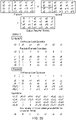
- Matrix multiplication involving small dimensions can be a common use case in various algorithms involved in HPC, DSP and Networking domains. It is also the backbone of block-based transform operations in which a small-dimension square matrix multiplication operation is performed on a larger frame data such as pixel values, as is commonly used in video and image processing algorithms.
- a matrix with small dimensions poses a unique problem for vectorization, in which the dimension of input data forms the limiting factor for optimization and not the vector length. Hence increasing vector length will not improve performance and these algorithms cannot scale up with higher vector length.
- Vector implementations with a wide vector length are most affected by this problem. The example below illustrates this problem.
- M 3: a b c
- One approach for vectorising scalar matrix multiplication is by reading an entire row/column (or part of a row/column if the vector length is smaller than the row/column length) to a vector register and processing multiple elements in parallel to generate the output values.
- This approach scales up well with vector length as long as there are enough data to fill the vector register in each iteration, i.e. for matrixes with dimension greater than that of vector length. With higher vector length, more data can be packed in the vector register, thereby effectively reducing the number of iterations and improving performance.
- a "replicate partition instruction” which allow the programmer to replicate a portion of a vector register into another register. Partitions of arbitrary size can be defined within a result register, and a selected portion of a source register can be repeated in each partition. This helps to implement the vector-of-vectors approach for wide vector length machines in algorithms dealing with small dimension of data, and thereby allowing to scale up the performance with vector length in a vector length agnostic way. Example use cases showing how the instructions can help speed up arithmetic operations will be discussed below, but first a number of variants of the instructions themselves are described.
- the "active bits" in the control mask are considered to be those bits equal to 1, and the inactive bits are the bits equal to 0.
- the '0' bits as the active bits and '1' bits as inactive.
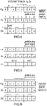
- Figure 3 shows a first example of a source-transforming form of a replicate partition instruction, which specifies a destination vector register Zd for storing a result vector, a predicate register Pg specifying a control mask value for identifying an active portion of the result vector, a source vector register Zs for storing a source vector, and a second predicate register Ps specifying a partition mask value which provides partition information identifying a configuration of a number of partitions within the result vector as well as element selection information identifying the position of a selected element of the source vector marking the start of a sequence of adjacent data elements to be mapped to each partition.
- the active portion is identified as the portion of the result vector corresponding to the active bits of the control mask Pg.
- the partition size can be defined either by the size of the portion of Ps between the first and last active bits, or by the portion of Ps in which all bits are set active (for the example with partition size of 2 shown in Figure 3 both options are equivalent, but if the partition size is 3 or more then with the first approach intervening bits may take any value while with the second approach the intervening bits between the first/last active bits would also be active).
- the decode circuitry 20 controls the vector permute unit 80 to generate the result vector Zd in which each partition is filled with the data values of a sequence of elements of the source vector Zs starting from the selected element position.
- the selected element position is element 5 of Zs, and so each partition of the result vector is filled with a sequence of data values starting with the data value f in element 5.
- the partitions comprising 2 data elements therefore comprise the sequence of data values f, g and the partition comprising a single data element has that element set to the data value f of the selected data element position.
- this instruction can be used to repeat multiple instances of the same sequence of data values throughout a vector, which can be useful for processing of matrices or other data structures of relatively small dimension compared to the vector length as discussed below.
- Figure 4 shows a second example of the replicate partition instruction, which again specifies a source register Zs and destination register Zd, but which specifies a single predicate register Pg for defining the active region and the partition configuration.
- the selected data element position marking the start of the sequence of data values to be extracted from the source vector
- the first active bit in predicate value Pg indicates the partition size (the size being encoded in terms of the number of bits between the first active bit and the least significant bit).
- the last active bit of the predicate value indicates the size of the active region of the result vector Zd (again defined relative to the least significant bit). Bits of Pg between the first and last active bits are marked with "x" to indicate that they can take any value as they do not affect the result.
- the partition size is 3 (as the first active bit is at the third least significant bit of Pg) and the active region size is 7 (as the last active bit is at the seventh least significant bit of Pg).
- the result Zd is configured with three partitions, the first two comprising 3 elements each and the last partition comprising a single element as it is truncated to fit in the active region.
- the last element of Zd is inactive.
- a sequence of data values a, b, c starting from the least significant data element position of Zs is mapped to the lower two partitions, and the last truncated partition comprises a partial sequence comprising data value 'a'.
- Figure 5 shows a second example using the same encoding technique as in Figure 4 .
- the partition size and active region size are the same, and the instruction will simply populate the active region of the destination register Zd with the corresponding elements of Zs, with the remaining elements of Zd inactive.
- Figure 6 which also uses the same encoding technique, to replicate a partition of the specified size throughout the entire vector register, the most significant bit of the mask Pg can be marked as active.
- the inactive elements of the result vector Zd can be handled in different ways.
- the inactive elements outside the active region can each be filled with a predetermined data value, such as zero ("zeroing predication").
- the previous value stored in those inactive elements of the destination register Zd may be retained, so that the newly allocated partitions are merged with the previous contents of Zd ("merging predication").
- replicate partition instruction can also be provided.
- an unpredicated variant of the instruction shown in Figure 3 which does not specify a control mask Pg, may be provided which controls the processor to replicate the partition throughout the destination register.
- the partition size and selected data element position can still be encoded using Ps in the same way as in Figure 3 , or alternatively the approach shown in Figure 4 can be used for defining the partition size.
- Figures 3 to 6 show constructive encodings where the instruction includes separate register specifiers for the source and result vectors respectively, other examples may use a destructive encoding where a single register specifies both the source value and the location to which the result vector is to be written. In this case, the result of the replicate partition instruction overwrites the source operand.
- Scalar variants of these instructions can also be provided in which any of the partition size, active region size, and selected data element position can be encoded through scalar values. For example:
- Rs1 and Rs2 can respectively indicate the start and end positions of the sequence of elements to be extracted from Zs, i.e. the partition size corresponds to Rs2 - Rs1 + 1.
- This provides a scalar equivalent to the encoding of Ps shown in Figure 3 , and allows for the sequence of data values to be extracted at an arbitrary location within Zs rather than by default starting at the least significant element.
- encoding errors e.g. where Rs2 ⁇ Rs1
- the variants discussed above are all examples of a source-transforming form of the replicate partition instruction, which operates on a source vector stored in a source register Zs or Zd and generates a result vector Zd in which data values from the source register are mapped to data elements of the result depending on the defined partition configuration.
- This can be viewed as a "fused" operation where one instruction both determines which elements of the source vector should be extracted and permutes those elements to the required positions in the result vector Zs.
- an alternative is to provide an index-generating form of the replicate partition instruction as shown in Figures 7 to 9 which populates the result vector with the element indices of the required elements from the source vector, but does not actually copy the data values.
- a subsequent permute instruction can then use the element indices of the result vector to control mapping of the elements indicated by the element indices in the source vector to a further result vector.
- a subsequent gather-type load instruction which loads data values from non-contiguous addresses determined using offsets read from a source vector, can use the result generated by the index-generating form of the replicate partition instruction as the vector of offsets, to control loading of the required data values from memory into a destination register.
- This approach can be regarded as an "split" or "unfused” operation, where the overall operation to pack the required data into a vector register is carried out using two separate instructions (the index-generating replicate-partition instruction and a subsequent load or permute instruction). While this may be slower in terms of performance than a single fused instruction as discussed above, it may simplify the micro-architectural hardware design in some instances, e.g. it can allow reuse of hardware for implementing a generic permute operation or gather load.
- Figure 7 shows a first example of the index-generating form of the replicate partition instruction INCRR Zdst, Rs1, Rs2, where Zdst is the destination register for storing the result vector and Rs1 and Rs2 are scalar values specifying a reset value and stride respectively.
- This example is an unpredicated instruction and so the entire result vector is considered to be the active portion.
- a predicated version could also be provided where a parameter of the instruction identifies the active portion.
- the result vector is filled with a number of repetitions of a repeating pattern of element indices, where Rs1 defines the reset value specifying the index value to be written to the first element of each repeating pattern, and Rs2 defines the stride indicating the period of repetition (the number of elements in each partition).
- the indices following the first element are generated by incrementing the previous element index by 1.
- the result vector is filled with a number of repetitions of the sequence of elements (3, 2, 1, 0) up to the end of the vector, i.e. the result is [3, 2, 1, 0, 3, 2, 1, 0].
- the result vector would be filled with repetitions of a repeating sequence (4, 3, 2) to give a result of the form [..., 4, 3, 2, 4, 3, 2].
- the stride parameter Rs2 can be seen as equivalent to the partition size information, as it controls the size of each partition
- the reset parameter Rs1 can be seen as equivalent to the element selection information, as it controls the element from which each incrementing sequence of element indices starts.
- the ability to define "invalid" element indices can be useful for implementing "padding” between successive repetitions of the "valid" element indices. If a subsequent instruction simply ignores the "out of range” element indices (e.g. treating those lanes in a similar way to lanes which are masked out by a predicate), then the result can be that the repetitions of the repeating pattern of valid data elements are separated by one or more lanes of padding, which could be useful for some applications.
- the third scalar register Rs3 could identify a difference between the starting index for one partition and the starting index for the next partition.
- the first partition may comprise a sequence of indices starting at Rs1
- the next partition may comprise a sequence of indices starting at Rs1+Rs3
- the next partition may comprise a sequence of indices starting at Rs1+2*Rs3, and so on.
- this is an example of an instruction where the selected element position for each partition can be different for each partition.
- the load-replicate or source-transforming forms of the instruction could also specify a similar stride parameter to Rs3 to encode different element positions to use as the start/end of the sequence for each partition.
- Figure 9 shows another variant of the index-generating form of the replicate partition instruction, which specifies a scalar register Rs1 defining which element is the selected element from which the incrementing sequence of element indices starts in each partition, and a control mask Ps1 where the positions of the active bits mark the start of each partition (alternatively, the active bits could mark the end of each partition).
- a similar encoding for the partition information using a general mask supporting varying partition length could also be used for the source-transforming or load-replicate types of the replicate partition instruction.
- Figure 10 shows a load-replicate form of the replicate partition instruction.
- the load-replicate form of the instruction specifies a base address register Ra which stores a value used to calculate a base address #[Ra].
- the block of data stored at memory addresses starting at the base address can be viewed as effectively representing the "source vector" from which the sequence of data values is to be extracted and repeated in each partition of the destination register Zdst. That is, if a separate contiguous vector load instruction was executed specifying the same base address #[Ra], this would result in a vector register comprising the sequence of elements A0, A1, A2...
- a subsequent source-transforming form of the instruction could be executed as discussed above to populate the partitions of a result vector with elements extracted from the source vector.
- the load-replicate form of the replicate partition instruction avoids the need for such a separate vector load instruction, by instead operating directly on the "source vector" in memory to give an equivalent result.
- the load-replicate form may use any of the techniques discussed above for encoding the partition size/position, active region location, and selected data element position.
- the particular example of Figure 10 is similar to the first of the scalar examples of the source-transforming instruction discussed above, in that it specifies two scalar registers Rs1, Rs2 to define the size of the partition and the size of the active region respectively, and by default the selected data element position and active region start position are both implicitly the least significant element position.
- the load-replicate instruction would control the processor to load the data values corresponding to the first three elements A0, A1, A2 of "the source vector" stored in memory at addresses starting at the base address #[Ra], and repeat these three data values A0, A1, A2 multiple times within the active region of the vector.
- Figure 10 is just one example, and other examples of the load-replicate form of the replicate partition instruction may mirror the partition encoding used by any of the other examples of the source-transforming form or index-generating form of the instruction described above.
- the load-replicate form of the replicate partition instruction may only need to load certain selected elements from the source vector stored in memory, in practice some hardware implementations may nevertheless load the entire structure A0, A1, A2... (or a sub-portion of the structure) from memory into a buffer, and then pick out the required elements to be written to the result destination register.
- the instruction may result in some data being read from the memory even if it is not actually required for generating the result vector.
- This approach may in some cases be more convenient than reading out selected values from the required offsets.
- the memory system hardware may impose a minimum size on the block of data read from memory in a single transaction, and so if any part of that block is required then this may require the entire block to be read.
- the minimum granularity at which memory is read corresponds to the block of values A0, A1, A2, A3 in the example of Figure 10 .
- the entire block A0-A3 may still be read, but A3 can be discarded by the processor.
- the load-replicate instruction it is not essential for the load-replicate instruction to load only the required data values - other values may also be loaded as an artefact of the way the particular memory system operates. Nevertheless, by avoiding the need to consume a vector register, the load-replicate instruction can alleviate register pressure which can help to improve performance.
- the sequence of data values or element indices allocated to each partition starts at the selected data element position.
- the selected data element position is element 1
- a partition of size 2 would comprise data values or element indices of elements 1 and 2
- a partition of size 3 would comprise data values of element indices of elements 1 to 3, and so on.
- each partition of the result vector could populate with a sequence ending with the selected data element position.
- the selected data element position is element 5
- a partition of size 3 would comprise data values or element indices corresponding to elements 3, 4, 5
- a partition of size 4 would comprise data values or element indices corresponding to elements 2, 3, 4, 5 and so on. This could be useful for accommodating processing of other types of data structure (e.g. an upper triangular matrix).
- Figure 11 shows a flow diagram illustrating a method of processing the replicate partition instruction.
- the instruction decoder 20 decodes the next instruction in the queue of instructions fetched from the cache 15.
- the decoder 20 determines whether the next instruction is a replicate partition instruction. If not, then at step 104 the decoder 20 generates control signals for controlling subsequent stages of the pipeline to perform a processing operation appropriate to the type of instruction encountered, and the method returns to step 100.
- the decoder 20 If a replicate partition instruction is encountered, then at step 106, the decoder 20 generates control signals for controlling subsequent stages of the processing pipeline to generate a result vector in which positions of a number of variable size partitions are defined by the instruction. Each partition having more than one data element is populated with a sequence of data values from the source vector or element indices starting or ending at a selected data element position.
- Another type of instruction supported by the instruction decoder 20 is a replicate elements instruction, which identifies multiple segments within a result vector, each of variable size as specified by the instruction.
- the decoder 20 controls the processing circuitry to generate a result vector in which, in each respective segment, a repeating value is repeated throughout that segment of the result vector, where the repeating value comprises either a data value of a selected data element of the corresponding segment of a source vector or an element index of that selected data element.
- this can be useful for speeding up operations such as matrix arithmetic where the dimension of the data being processed is smaller than the vector length.
- Figure 12 shows a first example of the replicate elements instruction, which specifies a destination vector register Zd for storing the result vector, a source vector register Zs for storing a source vector, and two predicate registers Pg, Ps.
- the predicate register Pg provides segment information identifying the size and position of each segment in the result vector.
- the segment information is encoded as a segment mask in which the positions of the active bits (1 in this example) mark the end of each segment.
- this encoding supports segments with different sizes within the same vector.
- Pg is set so that the first segment ends at element 1, the second segment ends at element 2 (so comprises only a single element), and the third segment ends at element 6.
- the predicate register Pg also provides active region information which identifies an active portion of the result vector. In this example, the active region starts at element 0 of the result vector and ends at the element corresponding to the most significant active bit in the predicate Pg (element 6 in this example).
- element 7 of the result vector in this example lies outside the active region.
- both the segment size information and the active region information can be encoded in the same register.
- the marker bits could represent the start of each segment rather than the end, in a similar way to the encoding of the partition start positions shown in Figure 9 for the replicate partition instruction.
- the second predicate register Ps provides element selection information indicating which of the data elements of the source vector Zs is a selected element within each of the segments identified by Pg. Within each segment, the selected element is the element corresponding to the least significant active bit in Ps. Hence, in the example of Figure 12 , the selected element in the first segment is element 0, the selected element in the second segment is element 2, and the selected element in the third segment is element 4. Rather than using the least significant active bit, it will be appreciated that the selected element could also be signalled using the most significant active bit within a given segment.
- the instruction decoder 20 controls the processing circuitry (e.g. the vector permute unit 80) to generate the result Zd in which, in each segment, the data value of source vector Zs at the selected element position of the corresponding segment is repeated throughout the corresponding segment of the result.
- the processing circuitry e.g. the vector permute unit 80
- the elements outside the active region of the result can be set to 0 as shown in Figure 12 and the "zeroing" example of Figure 13 , or could retain the previous values stored in the corresponding elements of the destination register as shown in the "merging" example of Figure 13 .
- Pg is an all true predicate (all active bits)
- the instruction can also be used to replicate a particular element throughout the vector register, i.e. to consider the entire vector region as a single segment, by marking the most significant vector lane as active in Pg as shown in Figure 14 .
- this encoding can avoid the need for any separate instruction to be provided for controlling replication of a single element throughout the vector, as this is a valid encoding of the replicate elements instruction which also supports multiple segments.
- an unpredicated variant of the instruction can also be provided, in which Pg only encodes the segment size, not the active region, and the entire vector register is considered active.
- the last segment corresponds to the portion of the result vector extending from the next element after the last active bit of Pg up to the end of the vector.
- the last active bit of Pg is at element 4 and so the last segment of the result vector Zd comprises elements 5 to 7 and these elements of the result are set equal to the data value "f" in the selected element 5 of the corresponding segment of the source vector Zs, as identified by Ps.
- variants of the instruction may use different combinations of predicate and scalar values to convey the segment size information, active portion information and element selection information.
- Some examples of such variants include:
- the relative position of the selected element with respect to each segment is constrained to be the same in each segment (e.g. Xs1 specifies a value N indicating that the Nth element in each segment is the selected element).
- each of the active region information, segment size information and element selection information are encoded as scalar variables stored in scalar registers.
- each segment would have the same size (although the first or last segment can be truncated to fit in the active region if necessary).
- Xs1 indicates the element position marking the end of the active region
- Xs2 indicates the length of each segment
- Xs3 indicates which element of the source vector is the selected element in each segment (relative to the start of the segment).
- the constructive variant separate source and destination registers are defined, so that the source vector is retained following execution of the instruction.
- the same register acts as both source and destination register, so that the source vector is overwritten with the result vector.
- Xs1 ⁇ Xs2 and Xs2 ⁇ Xs3 for most uses of the instructions. If an instruction is encountered where the partition size Xs2 is greater than the size of the active region Xs1, the instruction could be treated as a NOP or a zeroing or merging predication could be applied to mask the parts of the segment which stray into the inactive region. Similarly, cases where the element position indicated by Xs3 is larger than the segment size could be treated as NOP or could result in each segment being masked by zeroing or merging predication. Whether the NOP or the masking approach is taken could be predefined (hardcoded) for a particular implementation, or could vary depending on the type of instruction.
- Xs1 indicates the segment size
- Xs2 indicates the selected element position
- the entire result vector is treated as the active portion as in the example of Figure 15 above.
- an unpredicated destructive encoding could also be provided: REP_ELEMENTS Zds, Xs1, Xs2.
- the last segment is truncated (e.g. if the vector length is 8, the entire vector is considered active, and the segment size is 3, the result vector will comprise three segments of sizes 3, 3, 2 respectively).
- the first segment could be truncated instead of the last segment.
- the examples above are source-transforming forms of the replicate elements instruction, which extract the data values of selected elements from a source vector stored in a vector register 60 and repeat them within corresponding segments of the result vector.
- a combined load-replicate form of the replicate elements instruction can also be provided, in a similar way to the load-replicate form of the replicate partition instruction discussed above for Figure 10 .
- the "source vector" from which elements are extracted is stored in memory rather than in a register (with the base address #[Ra] of the source vector in memory being determined based on a value in a base register Za), but otherwise the way in which the segment size, active portion and element selection information is encoded can be the same as any of the variants discussed above for the source-transforming replicate element instruction.
- the example of Figure 17 mirrors the unpredicated scalar variant 3 described above.
- Rs1 defines a constant stride corresponding to the segment size and Rs2 defines the element position within a segment.
- Similar examples of a load-replicate replicate elements instruction can be provided corresponding to the other variants. For instance, different values for stride and segment length could be specified, to help pad the partition to a required alignment as part of the load operation, or predication can be provided by defining an active region as discussed above.
- an index-generating form of the replicate elements instruction can also be provided, similar to Figures 7 and 8 above, which triggers the pipeline to replicate the element index of the selected element of the source vector throughout the corresponding segment of the result vector, rather than replicating the data value of that element.
- Figure 19 shows a flow chart illustrating a method of processing a replicate elements instruction.
- the instruction decoder 20 decodes the next instruction in the queue of instructions fetched from the cache 15.
- the decoder 20 determines whether the next instruction is a replicate partition instruction. If not, then at step 124 the decoder 20 generates control signals for controlling subsequent stages of the pipeline to perform a processing operation appropriate to the type of instruction encountered, and the method returns to step 120.
- the decoder 20 controls the processing pipeline to generate the result vector in which, in each variable size segment, a repeating value is repeated throughout the segment.
- the segments can be of different sizes or could all be the same size, and the size/position of each segment is encoded within the instruction.
- the segments may only be defined within an active portion of the result vector, while for an unpredicated instruction the segments may fill the entire vector.
- the repeating value for a given segment is either a data value of a selected element of a corresponding segment of a source vector, or an element index of the selected data element. Which element is the selected data element is encoded within the instruction, and can be the same relative position in each segment, or can vary from segment to segment.
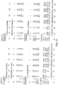
- a matrix multiplication on dimension MxM, where N rows can be packed into a single vector register can be implemented using code as follows. Note that this example uses the scalar form of the replicate instructions, in which the mask (number of active elements) is expressed as an integer - see the mask parameter in VecRepElementS and VecRepPartitionS). However, other examples could use a predicate form of the instruction where the mask is expressed in a predicate register instead of a scalar integer register. In this case, the boundary condition check is not required as it would be taken care of when generating the predicate mask as part of the loop iteration (the same applies to other examples below).
- the replicate partition instruction replicates the values from one row of matrix b multiple times within the result vector.
- the replicate elements instruction defines segments of length M (corresponding to the matrix row size), and in each segment replicates a single element of matrix a that is to be multiplied with each of the values in the corresponding row of matrix b. Over the three iterations, a given lane of vector processing has three multiplications performed (E.g.
- the matrices are square matrices (MxM), but it will be appreciated that the replicate elements and replicate partition instructions could also be used to calculate multiplications of matrices where the row length and column length are different.
- an alternative loop could use the load-replicate form of the instruction instead, so that there is also no need for the VecLoad() instruction, or alternative the index-generating form of the instructions could be used followed by a subsequent Vector load or permute instruction.
- the replicate partition and replicate elements instructions can also be used for an operation where each block within a frame of data values is to be multiplied by a smaller matrix.
- a MxM matrix multiplication of small dimension may need to be performed between a kernel matrix [z] and each MxM block of an entire frame of data [a]: a , input frame data a 0 a 1 a 2 a 3 a 4 a5 a 6 a 7 ... b 0 b 1 b 2 b 3 b 4 b 5 b 6 b 7 ... c 0 c 1 c 2 c 3 c 4 c 5 c 6 c 7 ⁇ d 0 d 1 d 2 d 3 d 4 d 5 d 6 d 7 ... ⁇ ⁇ ⁇ ⁇ ⁇ ⁇ ⁇ ⁇ z , kernel z 0 z1 z 2 z 3 z 4 z 5 z 6 z 7 z 8
- matrixMultiplication is vectorised as in the traditional approach discussed above on page 13 and will compute the result of each MxM block matrix multiplication.
- the above algorithm can be converted to operate on a complete row in the frame by packing data corresponding to multiple MxM blocks together and processing multiple blocks in parallel.
- a reference implementation using this approach is:
- FIG. 20-22 A further example use case is shown in Figures 20-22 .
- This example uses the replicate elements instruction but not the replicate partition instruction.
- a frame can be divided into multiple tiles, and these tiles may be of a different size.
- each section of the frame in Figure 20 represents a tile of 2x2 or 4x4 size. These tiles are multiplied with the corresponding tile in the other frame to generate the resultant frame.
- Such a tile-based approach is useful for many video processing algorithms. Assuming a vector processing engine with wide vector registers, multiple tiles of different sizes can be processed in a single iteration of a vector loop.
- multiplication of two adjacent tiles of different sizes (2x2 and 4x4) is done in the same iteration.
- iterations 1 and 2 calculate the upper 2x2 tile t0-t3 and iterations 3 and 4 calculate the lower 2x2 tile w0-w3 (with an unshown predicate operation used to mask out the appropriate parts of some of the vector registers v1-v8), while all 4 operations calculate parts of the 4x4 tile u0-u15.
- the replicate element operation the operation can be done with fewer instructions than if each vector instruction could only operate on a single 2x2 or 4x4 tile.
- the instruction variants which support varying partition size within the same register can be useful for supporting processing of other non-rectangular grid patterns, including the following:
- the replicate partition instruction can also be used to replicate the twiddle factors for FFT algorithm for a given stage.
- the twiddle factors can be replicated in several partitions and can be processed in parallel.
- stage 2 we can replicate the twiddle factor as follows: [W0, W2, -, -, -, -, -] -> [W0,W2, W0,W2, W0,W2, W0,W2].
- this is an example of a use case where the replicate partition instruction can be used separately from the replicate elements instruction.
- Figure 24 illustrates a virtual machine implementation that may be used. Whilst the earlier described embodiments implement the present invention in terms of apparatus and methods for operating specific processing hardware supporting the techniques concerned, it is also possible to provide so-called virtual machine implementations of hardware devices. These virtual machine implementations run on a host processor 530 running a host operating system 520 supporting a virtual machine program 510. Typically, large powerful processors are required to provide virtual machine implementations which execute at a reasonable speed, but such an approach may be justified in certain circumstances, such as when there is a desire to run code native to another processor for compatibility or re-use reasons.
- the virtual machine program 510 provides an application program interface to an application program 500 which is the same as the application program interface which would be provided by the real hardware which is the device being modelled by the virtual machine program 510.
- the program instructions including the control of memory accesses described above, may be executed from within the application program 500 using the virtual machine program 510 to model their interaction with the virtual machine hardware.
- the words “configured to" are used to mean that an element of an apparatus has a configuration able to carry out the defined operation.
- a “configuration” means an arrangement or manner of interconnection of hardware or software.
- the apparatus may have dedicated hardware which provides the defined operation, or a processor or other processing device may be programmed to perform the function.
- Configured to does not imply that the apparatus element needs to be changed in any way in order to provide the defined operation.
Landscapes
- Engineering & Computer Science (AREA)
- Software Systems (AREA)
- Theoretical Computer Science (AREA)
- Physics & Mathematics (AREA)
- General Engineering & Computer Science (AREA)
- General Physics & Mathematics (AREA)
- Mathematical Physics (AREA)
- Complex Calculations (AREA)
- Advance Control (AREA)
- Executing Machine-Instructions (AREA)
- Separation By Low-Temperature Treatments (AREA)
- Bidet-Like Cleaning Device And Other Flush Toilet Accessories (AREA)
Claims (13)
- Appareil comprenant :des circuits de traitement (80) destinés à effectuer des opérations de traitement vectoriel sur des vecteurs comprenant une pluralité d'éléments de données, etun décodeur d'instructions (20) destiné à décoder des instructions de programmation pour piloter les circuits de traitement pour qu'ils effectuent les opérations de traitement vectoriel,dans lequel, en réponse à une instruction de réplication d'élément spécifiant des informations de segments définissant des positions d'une pluralité de segments de taille variable dans un vecteur résultat, chaque segment comprenant au moins un élément de données du vecteur résultat et au moins un segment comprenant une pluralité d'éléments adjacents du vecteur résultat, le décodeur d'instructions est configuré pour piloter les circuits de traitement afin de générer un vecteur résultat dans lequel, dans chaque segment respectif, le codage de l'instruction de réplication d'élément contraint les circuits de traitement à répéter une valeur de répétition sur tout ce segment du vecteur résultat, la valeur de répétition comprenant une valeur de données à une position sélectionnée d'élément de données du segment correspondant d'un vecteur source ou un index d'élément indiquant ladite position sélectionnée d'élément de données.
- Appareil selon la revendication 1, dans lequel les informations de segment comprennent des informations de masque de segment comprenant au moins un bit marqueur identifiant le début ou la fin d'un segment à l'intérieur du vecteur résultat.
- Appareil selon la revendication 1, dans lequel les informations de segment comprennent des informations de taille de segment indiquant le nombre d'éléments de données par segment.
- Appareil selon la revendication 3, dans lequel le codage de l'instruction de réplication d'élément contraint tous les segments différents du premier ou du dernier segment à comporter le même nombre d'éléments de données.
- Appareil selon l'une quelconque des revendications 1 à 4, dans lequel l'instruction de réplication d'élément spécifie des informations de sélection d'élément indiquant la position l'élément de données sélectionné pour chaque segment.
- Appareil selon la revendication 5, dans lequel les informations de sélection d'élément présentent un codage qui contraint la position d'élément de données sélectionné à être la même pour chaque segment.
- Appareil selon la revendication 5, dans lequel les informations de sélection d'élément comportent un codage qui identifie séparément la position d'élément de données sélectionné pour chacun de la pluralité de segments.
- Appareil selon l'une quelconque des revendications 1 à 7, dans lequel l'instruction de réplication d'élément spécifie des informations de partie active qui indiquent une partie active du vecteur résultat comprenant la pluralité de segments,
dans lequel, en réponse à l'instruction de réplication d'élément, le décodeur d'instructions est configuré pour piloter les circuits de traitement afin de générer le vecteur résultat dans lequel au moins un élément de données à l'extérieur de la partie active présente une valeur prédéterminée ou bien la valeur d'un élément de données correspondant d'un registre de destination destiné à stocker le vecteur résultat. - Appareil selon l'une quelconque des revendications 1 à 8, dans lequel, en réponse à une forme de transformation de source de l'instruction de réplication d'élément spécifiant un registre source stockant le vecteur source, le décodeur d'instructions est configuré pour piloter les circuits de traitement pour qu'ils génèrent le vecteur résultat dans lequel, dans chaque segment respectif, la valeur de répétition comprend la valeur de données à la position d'élément de données sélectionné du segment correspondant du vecteur source.
- Appareil selon l'une quelconque des revendications 1 à 9, dans lequel, en réponse à une forme de réplication de charge de l'instruction de réplication d'élément, le décodeur d'instructions est configuré pour piloter les circuits de traitement pour qu'ils chargent au moins une partie du vecteur source à partir d'une mémoire de données et pour qu'ils génèrent le vecteur résultat dans lequel, dans chaque segment respectif, la valeur de répétition comprend la valeur de données à la position d'élément de données sélectionné du segment correspondant du vecteur source.
- Appareil selon l'une quelconque des revendications 1 à 10, dans lequel, en réponse à une forme de génération d'index de l'instruction de réplication d'élément, le décodeur d'instructions est configuré pour piloter les circuits de traitement pour qu'ils génèrent le vecteur résultat dans lequel, dans chaque segment respectif, la valeur de répétition comprend l'index d'élément indiquant ladite position d'élément de données sélectionné.
- Procédé de traitement de données pour un appareil comprenant des circuits de traitement (80) destinés à effectuer des opérations de traitement vectoriel sur des vecteurs comprenant une pluralité d'éléments de données, le procédé comprenant :le décodage (120, 122) d'une instruction de réplication d'élément spécifiant des informations de segments définissant des positions d'une pluralité de segments de taille variable dans un vecteur résultat, chaque segment comprenant au moins un élément de données du vecteur résultat et au moins un segment comprenant une pluralité d'éléments adjacents du vecteur résultat, eten réponse à l'instruction de réplication d'élément, la génération (126) d'un vecteur résultat dans lequel, pour chaque segment respectif, le codage de l'instruction de réplication d'élément contraint les circuits de traitement à répéter une valeur de répétition sur tout ce segment du vecteur résultat, la valeur de répétition comprenant une valeur de données à une position d'élément de données sélectionné du segment correspondant d'un vecteur source ou un index d'élément indiquant ladite position d'élément de données sélectionné.
- Support de stockage pouvant être lu par ordinateur stockant un programme en machine virtuelle (510) comprenant des instructions qui, lorsqu'elles sont exécutées par un ordinateur (530), amènent l'ordinateur à exécuter le procédé de la revendication 12.
Priority Applications (7)
| Application Number | Priority Date | Filing Date | Title |
|---|---|---|---|
| EP16386020.8A EP3336691B1 (fr) | 2016-12-13 | 2016-12-13 | Instruction de réplication d'éléments |
| PCT/GB2017/053395 WO2018109428A1 (fr) | 2016-12-13 | 2017-11-10 | Instruction d'éléments de reproduction |
| CN201780076939.8A CN110073330B (zh) | 2016-12-13 | 2017-11-10 | 复制元素指令 |
| KR1020197018952A KR102447106B1 (ko) | 2016-12-13 | 2017-11-10 | 복제 요소 명령어 |
| JP2019530214A JP7053620B2 (ja) | 2016-12-13 | 2017-11-10 | 要素レプリケート命令 |
| US16/468,108 US11977884B2 (en) | 2016-12-13 | 2017-11-10 | Replicate elements instruction |
| TW106142869A TWI759373B (zh) | 2016-12-13 | 2017-12-07 | 複製元件指令 |
Applications Claiming Priority (1)
| Application Number | Priority Date | Filing Date | Title |
|---|---|---|---|
| EP16386020.8A EP3336691B1 (fr) | 2016-12-13 | 2016-12-13 | Instruction de réplication d'éléments |
Publications (2)
| Publication Number | Publication Date |
|---|---|
| EP3336691A1 EP3336691A1 (fr) | 2018-06-20 |
| EP3336691B1 true EP3336691B1 (fr) | 2022-04-06 |
Family
ID=57755165
Family Applications (1)
| Application Number | Title | Priority Date | Filing Date |
|---|---|---|---|
| EP16386020.8A Active EP3336691B1 (fr) | 2016-12-13 | 2016-12-13 | Instruction de réplication d'éléments |
Country Status (7)
| Country | Link |
|---|---|
| US (1) | US11977884B2 (fr) |
| EP (1) | EP3336691B1 (fr) |
| JP (1) | JP7053620B2 (fr) |
| KR (1) | KR102447106B1 (fr) |
| CN (1) | CN110073330B (fr) |
| TW (1) | TWI759373B (fr) |
| WO (1) | WO2018109428A1 (fr) |
Families Citing this family (2)
| Publication number | Priority date | Publication date | Assignee | Title |
|---|---|---|---|---|
| US10409601B2 (en) * | 2017-12-29 | 2019-09-10 | Intel Corporation | Apparatus and method for loop flattening and reduction in a single instruction multiple data (SIMD) pipeline |
| US11477007B1 (en) * | 2021-04-13 | 2022-10-18 | International Business Machines Corporation | Packing arbitrary tensors into tiles with descriptive shapes |
Family Cites Families (47)
| Publication number | Priority date | Publication date | Assignee | Title |
|---|---|---|---|---|
| US5822786A (en) | 1994-11-14 | 1998-10-13 | Advanced Micro Devices, Inc. | Apparatus and method for determining if an operand lies within an expand up or expand down segment |
| GB9509987D0 (en) | 1995-05-17 | 1995-07-12 | Sgs Thomson Microelectronics | Manipulation of data |
| US6895421B1 (en) | 2000-10-06 | 2005-05-17 | Intel Corporation | Method and apparatus for effectively performing linear transformations |
| US7155601B2 (en) | 2001-02-14 | 2006-12-26 | Intel Corporation | Multi-element operand sub-portion shuffle instruction execution |
| US7631025B2 (en) * | 2001-10-29 | 2009-12-08 | Intel Corporation | Method and apparatus for rearranging data between multiple registers |
| US7725521B2 (en) | 2001-10-29 | 2010-05-25 | Intel Corporation | Method and apparatus for computing matrix transformations |
| US7685212B2 (en) | 2001-10-29 | 2010-03-23 | Intel Corporation | Fast full search motion estimation with SIMD merge instruction |
| US20040054877A1 (en) * | 2001-10-29 | 2004-03-18 | Macy William W. | Method and apparatus for shuffling data |
| US7853778B2 (en) | 2001-12-20 | 2010-12-14 | Intel Corporation | Load/move and duplicate instructions for a processor |
| JP3958662B2 (ja) | 2002-09-25 | 2007-08-15 | 松下電器産業株式会社 | プロセッサ |
| US7127592B2 (en) | 2003-01-08 | 2006-10-24 | Sun Microsystems, Inc. | Method and apparatus for dynamically allocating registers in a windowed architecture |
| US20070106882A1 (en) | 2005-11-08 | 2007-05-10 | Stexar Corp. | Byte-wise permutation facility configurable for implementing DSP data manipulation instructions |
| US7685109B1 (en) | 2005-12-29 | 2010-03-23 | Amazon Technologies, Inc. | Method and apparatus for data partitioning and replication in a searchable data service |
| US7885988B2 (en) | 2006-08-24 | 2011-02-08 | Dell Products L.P. | Methods and apparatus for reducing storage size |
| US9678775B1 (en) | 2008-04-09 | 2017-06-13 | Nvidia Corporation | Allocating memory for local variables of a multi-threaded program for execution in a single-threaded environment |
| US8745360B2 (en) * | 2008-09-24 | 2014-06-03 | Apple Inc. | Generating predicate values based on conditional data dependency in vector processors |
| GB2464292A (en) | 2008-10-08 | 2010-04-14 | Advanced Risc Mach Ltd | SIMD processor circuit for performing iterative SIMD multiply-accumulate operations |
| US8776090B2 (en) | 2009-02-17 | 2014-07-08 | Broadcom Corporation | Method and system for network abstraction and virtualization for a single operating system (OS) |
| US8996845B2 (en) | 2009-12-22 | 2015-03-31 | Intel Corporation | Vector compare-and-exchange operation |
| KR101779992B1 (ko) | 2010-02-24 | 2017-10-10 | 마벨 월드 트레이드 리미티드 | 데이터 저장 디바이스들에 대한 액세스들의 공간적인 분포에 기초하는 캐싱 |
| US8595469B2 (en) | 2010-06-24 | 2013-11-26 | International Business Machines Corporation | Diagnose instruction for serializing processing |
| US8868885B2 (en) | 2010-11-18 | 2014-10-21 | Ceva D.S.P. Ltd. | On-the-fly permutation of vector elements for executing successive elemental instructions |
| GB2485774A (en) * | 2010-11-23 | 2012-05-30 | Advanced Risc Mach Ltd | Processor instruction to extract a bit field from one operand and insert it into another with an option to sign or zero extend the field |
| CN103502935B (zh) | 2011-04-01 | 2016-10-12 | 英特尔公司 | 向量友好指令格式及其执行 |
| WO2013074781A1 (fr) | 2011-11-15 | 2013-05-23 | Ab Initio Technology Llc | Regroupement de données sur la base de demandes candidates |
| US9372812B2 (en) | 2011-12-22 | 2016-06-21 | Intel Corporation | Determining policy actions for the handling of data read/write extended page table violations |
| CN104126167B (zh) | 2011-12-23 | 2018-05-11 | 英特尔公司 | 用于从通用寄存器向向量寄存器进行广播的装置和方法 |
| US9336000B2 (en) * | 2011-12-23 | 2016-05-10 | Intel Corporation | Instruction execution unit that broadcasts data values at different levels of granularity |
| CN104011649B (zh) * | 2011-12-23 | 2018-10-09 | 英特尔公司 | 用于在simd/向量执行中传播有条件估算值的装置和方法 |
| CN104137061B (zh) * | 2011-12-30 | 2017-12-22 | 英特尔公司 | 用于执行向量频率扩展指令的方法、处理器核和计算机系统 |
| US9575753B2 (en) | 2012-03-15 | 2017-02-21 | International Business Machines Corporation | SIMD compare instruction using permute logic for distributed register files |
| US9098265B2 (en) | 2012-07-11 | 2015-08-04 | Arm Limited | Controlling an order for processing data elements during vector processing |
| US9342479B2 (en) * | 2012-08-23 | 2016-05-17 | Qualcomm Incorporated | Systems and methods of data extraction in a vector processor |
| US9606961B2 (en) | 2012-10-30 | 2017-03-28 | Intel Corporation | Instruction and logic to provide vector compress and rotate functionality |
| EP3093758B1 (fr) | 2013-03-15 | 2020-06-24 | Oracle International Corporation | Instruction à longueur de plage pour des processeurs de données multiples à instruction unique |
| WO2014142972A1 (fr) | 2013-03-15 | 2014-09-18 | Intel Corporation | Procédés et systèmes de vectorisation de boucles scalaires de programme informatique présentant des dépendances transmises par les boucles |
| US9237014B2 (en) | 2013-05-28 | 2016-01-12 | Hong Kong Applied Science & Technology Research Institute Company, Limited | Partial CipherText updates using variable-length segments delineated by pattern matching and encrypted by fixed-length blocks |
| US10423413B2 (en) | 2013-07-09 | 2019-09-24 | Texas Instruments Incorporated | Vector load and duplicate operations |
| GB2519107B (en) * | 2013-10-09 | 2020-05-13 | Advanced Risc Mach Ltd | A data processing apparatus and method for performing speculative vector access operations |
| US9557995B2 (en) | 2014-02-07 | 2017-01-31 | Arm Limited | Data processing apparatus and method for performing segmented operations |
| KR101818985B1 (ko) | 2014-03-28 | 2018-02-28 | 인텔 코포레이션 | 마스킹된 결과 요소들로의 전파를 이용하여 소스 요소들을 대응하는 마스킹되지 않은 결과 요소들에 저장하기 위한 프로세서, 방법, 시스템 및 명령어 |
| US20160179521A1 (en) | 2014-12-23 | 2016-06-23 | Intel Corporation | Method and apparatus for expanding a mask to a vector of mask values |
| US10445092B2 (en) * | 2014-12-27 | 2019-10-15 | Intel Corporation | Method and apparatus for performing a vector permute with an index and an immediate |
| US11544214B2 (en) | 2015-02-02 | 2023-01-03 | Optimum Semiconductor Technologies, Inc. | Monolithic vector processor configured to operate on variable length vectors using a vector length register |
| US20170177350A1 (en) | 2015-12-18 | 2017-06-22 | Intel Corporation | Instructions and Logic for Set-Multiple-Vector-Elements Operations |
| US10459843B2 (en) * | 2016-12-30 | 2019-10-29 | Texas Instruments Incorporated | Streaming engine with separately selectable element and group duplication |
| US11579881B2 (en) | 2017-06-29 | 2023-02-14 | Intel Corporation | Instructions for vector operations with constant values |
-
2016
- 2016-12-13 EP EP16386020.8A patent/EP3336691B1/fr active Active
-
2017
- 2017-11-10 KR KR1020197018952A patent/KR102447106B1/ko active IP Right Grant
- 2017-11-10 JP JP2019530214A patent/JP7053620B2/ja active Active
- 2017-11-10 WO PCT/GB2017/053395 patent/WO2018109428A1/fr active Application Filing
- 2017-11-10 CN CN201780076939.8A patent/CN110073330B/zh active Active
- 2017-11-10 US US16/468,108 patent/US11977884B2/en active Active
- 2017-12-07 TW TW106142869A patent/TWI759373B/zh active
Non-Patent Citations (1)
| Title |
|---|
| None * |
Also Published As
| Publication number | Publication date |
|---|---|
| US20190303155A1 (en) | 2019-10-03 |
| KR102447106B1 (ko) | 2022-09-26 |
| US11977884B2 (en) | 2024-05-07 |
| TW201828048A (zh) | 2018-08-01 |
| JP7053620B2 (ja) | 2022-04-12 |
| TWI759373B (zh) | 2022-04-01 |
| KR20190091489A (ko) | 2019-08-06 |
| JP2020501274A (ja) | 2020-01-16 |
| CN110073330A (zh) | 2019-07-30 |
| WO2018109428A1 (fr) | 2018-06-21 |
| EP3336691A1 (fr) | 2018-06-20 |
| CN110073330B (zh) | 2023-09-08 |
Similar Documents
| Publication | Publication Date | Title |
|---|---|---|
| US11947962B2 (en) | Replicate partition instruction | |
| KR102256188B1 (ko) | 데이터 처리장치 및 벡터 오퍼랜드를 처리하는 방법 | |
| US9965275B2 (en) | Element size increasing instruction | |
| US20230229730A1 (en) | Variable position shift for matrix processing | |
| US20230289186A1 (en) | Register addressing information for data transfer instruction | |
| EP3336691B1 (fr) | Instruction de réplication d'éléments | |
| US11106465B2 (en) | Vector add-with-carry instruction | |
| US20230214236A1 (en) | Masking row or column positions for matrix processing | |
| WO2023148467A1 (fr) | Technique permettant d'effectuer des opérations d'accès à la mémoire |
Legal Events
| Date | Code | Title | Description |
|---|---|---|---|
| PUAI | Public reference made under article 153(3) epc to a published international application that has entered the european phase |
Free format text: ORIGINAL CODE: 0009012 |
|
| STAA | Information on the status of an ep patent application or granted ep patent |
Free format text: STATUS: THE APPLICATION HAS BEEN PUBLISHED |
|
| AK | Designated contracting states |
Kind code of ref document: A1 Designated state(s): AL AT BE BG CH CY CZ DE DK EE ES FI FR GB GR HR HU IE IS IT LI LT LU LV MC MK MT NL NO PL PT RO RS SE SI SK SM TR |
|
| AX | Request for extension of the european patent |
Extension state: BA ME |
|
| STAA | Information on the status of an ep patent application or granted ep patent |
Free format text: STATUS: REQUEST FOR EXAMINATION WAS MADE |
|
| STAA | Information on the status of an ep patent application or granted ep patent |
Free format text: STATUS: EXAMINATION IS IN PROGRESS |
|
| 17P | Request for examination filed |
Effective date: 20190205 |
|
| RBV | Designated contracting states (corrected) |
Designated state(s): AL AT BE BG CH CY CZ DE DK EE ES FI FR GB GR HR HU IE IS IT LI LT LU LV MC MK MT NL NO PL PT RO RS SE SI SK SM TR |
|
| 17Q | First examination report despatched |
Effective date: 20190313 |
|
| STAA | Information on the status of an ep patent application or granted ep patent |
Free format text: STATUS: EXAMINATION IS IN PROGRESS |
|
| GRAP | Despatch of communication of intention to grant a patent |
Free format text: ORIGINAL CODE: EPIDOSNIGR1 |
|
| STAA | Information on the status of an ep patent application or granted ep patent |
Free format text: STATUS: GRANT OF PATENT IS INTENDED |
|
| INTG | Intention to grant announced |
Effective date: 20210511 |
|
| RAP3 | Party data changed (applicant data changed or rights of an application transferred) |
Owner name: ARM LIMITED |
|
| GRAJ | Information related to disapproval of communication of intention to grant by the applicant or resumption of examination proceedings by the epo deleted |
Free format text: ORIGINAL CODE: EPIDOSDIGR1 |
|
| STAA | Information on the status of an ep patent application or granted ep patent |
Free format text: STATUS: EXAMINATION IS IN PROGRESS |
|
| INTC | Intention to grant announced (deleted) | ||
| GRAP | Despatch of communication of intention to grant a patent |
Free format text: ORIGINAL CODE: EPIDOSNIGR1 |
|
| STAA | Information on the status of an ep patent application or granted ep patent |
Free format text: STATUS: GRANT OF PATENT IS INTENDED |
|
| INTG | Intention to grant announced |
Effective date: 20211110 |
|
| GRAS | Grant fee paid |
Free format text: ORIGINAL CODE: EPIDOSNIGR3 |
|
| GRAA | (expected) grant |
Free format text: ORIGINAL CODE: 0009210 |
|
| STAA | Information on the status of an ep patent application or granted ep patent |
Free format text: STATUS: THE PATENT HAS BEEN GRANTED |
|
| AK | Designated contracting states |
Kind code of ref document: B1 Designated state(s): AL AT BE BG CH CY CZ DE DK EE ES FI FR GB GR HR HU IE IS IT LI LT LU LV MC MK MT NL NO PL PT RO RS SE SI SK SM TR |
|
| REG | Reference to a national code |
Ref country code: GB Ref legal event code: FG4D |
|
| REG | Reference to a national code |
Ref country code: CH Ref legal event code: EP |
|
| REG | Reference to a national code |
Ref country code: AT Ref legal event code: REF Ref document number: 1482020 Country of ref document: AT Kind code of ref document: T Effective date: 20220415 |
|
| REG | Reference to a national code |
Ref country code: IE Ref legal event code: FG4D |
|
| REG | Reference to a national code |
Ref country code: DE Ref legal event code: R096 Ref document number: 602016070722 Country of ref document: DE |
|
| REG | Reference to a national code |
Ref country code: LT Ref legal event code: MG9D |
|
| REG | Reference to a national code |
Ref country code: NL Ref legal event code: MP Effective date: 20220406 |
|
| REG | Reference to a national code |
Ref country code: AT Ref legal event code: MK05 Ref document number: 1482020 Country of ref document: AT Kind code of ref document: T Effective date: 20220406 |
|
| PG25 | Lapsed in a contracting state [announced via postgrant information from national office to epo] |
Ref country code: NL Free format text: LAPSE BECAUSE OF FAILURE TO SUBMIT A TRANSLATION OF THE DESCRIPTION OR TO PAY THE FEE WITHIN THE PRESCRIBED TIME-LIMIT Effective date: 20220406 |
|
| PG25 | Lapsed in a contracting state [announced via postgrant information from national office to epo] |
Ref country code: SE Free format text: LAPSE BECAUSE OF FAILURE TO SUBMIT A TRANSLATION OF THE DESCRIPTION OR TO PAY THE FEE WITHIN THE PRESCRIBED TIME-LIMIT Effective date: 20220406 Ref country code: PT Free format text: LAPSE BECAUSE OF FAILURE TO SUBMIT A TRANSLATION OF THE DESCRIPTION OR TO PAY THE FEE WITHIN THE PRESCRIBED TIME-LIMIT Effective date: 20220808 Ref country code: NO Free format text: LAPSE BECAUSE OF FAILURE TO SUBMIT A TRANSLATION OF THE DESCRIPTION OR TO PAY THE FEE WITHIN THE PRESCRIBED TIME-LIMIT Effective date: 20220706 Ref country code: LT Free format text: LAPSE BECAUSE OF FAILURE TO SUBMIT A TRANSLATION OF THE DESCRIPTION OR TO PAY THE FEE WITHIN THE PRESCRIBED TIME-LIMIT Effective date: 20220406 Ref country code: HR Free format text: LAPSE BECAUSE OF FAILURE TO SUBMIT A TRANSLATION OF THE DESCRIPTION OR TO PAY THE FEE WITHIN THE PRESCRIBED TIME-LIMIT Effective date: 20220406 Ref country code: GR Free format text: LAPSE BECAUSE OF FAILURE TO SUBMIT A TRANSLATION OF THE DESCRIPTION OR TO PAY THE FEE WITHIN THE PRESCRIBED TIME-LIMIT Effective date: 20220707 Ref country code: FI Free format text: LAPSE BECAUSE OF FAILURE TO SUBMIT A TRANSLATION OF THE DESCRIPTION OR TO PAY THE FEE WITHIN THE PRESCRIBED TIME-LIMIT Effective date: 20220406 Ref country code: ES Free format text: LAPSE BECAUSE OF FAILURE TO SUBMIT A TRANSLATION OF THE DESCRIPTION OR TO PAY THE FEE WITHIN THE PRESCRIBED TIME-LIMIT Effective date: 20220406 Ref country code: BG Free format text: LAPSE BECAUSE OF FAILURE TO SUBMIT A TRANSLATION OF THE DESCRIPTION OR TO PAY THE FEE WITHIN THE PRESCRIBED TIME-LIMIT Effective date: 20220706 Ref country code: AT Free format text: LAPSE BECAUSE OF FAILURE TO SUBMIT A TRANSLATION OF THE DESCRIPTION OR TO PAY THE FEE WITHIN THE PRESCRIBED TIME-LIMIT Effective date: 20220406 |
|
| PG25 | Lapsed in a contracting state [announced via postgrant information from national office to epo] |
Ref country code: RS Free format text: LAPSE BECAUSE OF FAILURE TO SUBMIT A TRANSLATION OF THE DESCRIPTION OR TO PAY THE FEE WITHIN THE PRESCRIBED TIME-LIMIT Effective date: 20220406 Ref country code: PL Free format text: LAPSE BECAUSE OF FAILURE TO SUBMIT A TRANSLATION OF THE DESCRIPTION OR TO PAY THE FEE WITHIN THE PRESCRIBED TIME-LIMIT Effective date: 20220406 Ref country code: LV Free format text: LAPSE BECAUSE OF FAILURE TO SUBMIT A TRANSLATION OF THE DESCRIPTION OR TO PAY THE FEE WITHIN THE PRESCRIBED TIME-LIMIT Effective date: 20220406 Ref country code: IS Free format text: LAPSE BECAUSE OF FAILURE TO SUBMIT A TRANSLATION OF THE DESCRIPTION OR TO PAY THE FEE WITHIN THE PRESCRIBED TIME-LIMIT Effective date: 20220806 |
|
| REG | Reference to a national code |
Ref country code: DE Ref legal event code: R097 Ref document number: 602016070722 Country of ref document: DE |
|
| PG25 | Lapsed in a contracting state [announced via postgrant information from national office to epo] |
Ref country code: SM Free format text: LAPSE BECAUSE OF FAILURE TO SUBMIT A TRANSLATION OF THE DESCRIPTION OR TO PAY THE FEE WITHIN THE PRESCRIBED TIME-LIMIT Effective date: 20220406 Ref country code: SK Free format text: LAPSE BECAUSE OF FAILURE TO SUBMIT A TRANSLATION OF THE DESCRIPTION OR TO PAY THE FEE WITHIN THE PRESCRIBED TIME-LIMIT Effective date: 20220406 Ref country code: RO Free format text: LAPSE BECAUSE OF FAILURE TO SUBMIT A TRANSLATION OF THE DESCRIPTION OR TO PAY THE FEE WITHIN THE PRESCRIBED TIME-LIMIT Effective date: 20220406 Ref country code: EE Free format text: LAPSE BECAUSE OF FAILURE TO SUBMIT A TRANSLATION OF THE DESCRIPTION OR TO PAY THE FEE WITHIN THE PRESCRIBED TIME-LIMIT Effective date: 20220406 Ref country code: DK Free format text: LAPSE BECAUSE OF FAILURE TO SUBMIT A TRANSLATION OF THE DESCRIPTION OR TO PAY THE FEE WITHIN THE PRESCRIBED TIME-LIMIT Effective date: 20220406 Ref country code: CZ Free format text: LAPSE BECAUSE OF FAILURE TO SUBMIT A TRANSLATION OF THE DESCRIPTION OR TO PAY THE FEE WITHIN THE PRESCRIBED TIME-LIMIT Effective date: 20220406 |
|
| PLBE | No opposition filed within time limit |
Free format text: ORIGINAL CODE: 0009261 |
|
| STAA | Information on the status of an ep patent application or granted ep patent |
Free format text: STATUS: NO OPPOSITION FILED WITHIN TIME LIMIT |
|
| 26N | No opposition filed |
Effective date: 20230110 |
|
| PG25 | Lapsed in a contracting state [announced via postgrant information from national office to epo] |
Ref country code: AL Free format text: LAPSE BECAUSE OF FAILURE TO SUBMIT A TRANSLATION OF THE DESCRIPTION OR TO PAY THE FEE WITHIN THE PRESCRIBED TIME-LIMIT Effective date: 20220406 |
|
| PG25 | Lapsed in a contracting state [announced via postgrant information from national office to epo] |
Ref country code: SI Free format text: LAPSE BECAUSE OF FAILURE TO SUBMIT A TRANSLATION OF THE DESCRIPTION OR TO PAY THE FEE WITHIN THE PRESCRIBED TIME-LIMIT Effective date: 20220406 |
|
| P01 | Opt-out of the competence of the unified patent court (upc) registered |
Effective date: 20230429 |
|
| REG | Reference to a national code |
Ref country code: CH Ref legal event code: PL |
|
| REG | Reference to a national code |
Ref country code: BE Ref legal event code: MM Effective date: 20221231 |
|
| PG25 | Lapsed in a contracting state [announced via postgrant information from national office to epo] |
Ref country code: LU Free format text: LAPSE BECAUSE OF NON-PAYMENT OF DUE FEES Effective date: 20221213 |
|
| PG25 | Lapsed in a contracting state [announced via postgrant information from national office to epo] |
Ref country code: LI Free format text: LAPSE BECAUSE OF NON-PAYMENT OF DUE FEES Effective date: 20221231 Ref country code: IE Free format text: LAPSE BECAUSE OF NON-PAYMENT OF DUE FEES Effective date: 20221213 Ref country code: CH Free format text: LAPSE BECAUSE OF NON-PAYMENT OF DUE FEES Effective date: 20221231 |
|
| PG25 | Lapsed in a contracting state [announced via postgrant information from national office to epo] |
Ref country code: BE Free format text: LAPSE BECAUSE OF NON-PAYMENT OF DUE FEES Effective date: 20221231 |
|
| PGFP | Annual fee paid to national office [announced via postgrant information from national office to epo] |
Ref country code: GB Payment date: 20231121 Year of fee payment: 8 |
|
| PG25 | Lapsed in a contracting state [announced via postgrant information from national office to epo] |
Ref country code: IT Free format text: LAPSE BECAUSE OF FAILURE TO SUBMIT A TRANSLATION OF THE DESCRIPTION OR TO PAY THE FEE WITHIN THE PRESCRIBED TIME-LIMIT Effective date: 20220406 |
|
| PGFP | Annual fee paid to national office [announced via postgrant information from national office to epo] |
Ref country code: FR Payment date: 20231122 Year of fee payment: 8 Ref country code: DE Payment date: 20231121 Year of fee payment: 8 |
|
| PG25 | Lapsed in a contracting state [announced via postgrant information from national office to epo] |
Ref country code: HU Free format text: LAPSE BECAUSE OF FAILURE TO SUBMIT A TRANSLATION OF THE DESCRIPTION OR TO PAY THE FEE WITHIN THE PRESCRIBED TIME-LIMIT; INVALID AB INITIO Effective date: 20161213 |
|
| PG25 | Lapsed in a contracting state [announced via postgrant information from national office to epo] |
Ref country code: CY Free format text: LAPSE BECAUSE OF FAILURE TO SUBMIT A TRANSLATION OF THE DESCRIPTION OR TO PAY THE FEE WITHIN THE PRESCRIBED TIME-LIMIT Effective date: 20220406 |