EP3336585A1 - Steerable marine geophysical source - Google Patents
Steerable marine geophysical source Download PDFInfo
- Publication number
- EP3336585A1 EP3336585A1 EP17206894.2A EP17206894A EP3336585A1 EP 3336585 A1 EP3336585 A1 EP 3336585A1 EP 17206894 A EP17206894 A EP 17206894A EP 3336585 A1 EP3336585 A1 EP 3336585A1
- Authority
- EP
- European Patent Office
- Prior art keywords
- source
- geophysical
- housing structure
- marine vibrator
- towing
- Prior art date
- Legal status (The legal status is an assumption and is not a legal conclusion. Google has not performed a legal analysis and makes no representation as to the accuracy of the status listed.)
- Granted
Links
- 238000000034 method Methods 0.000 claims abstract description 36
- XLYOFNOQVPJJNP-UHFFFAOYSA-N water Substances O XLYOFNOQVPJJNP-UHFFFAOYSA-N 0.000 claims abstract description 33
- 230000008878 coupling Effects 0.000 claims description 4
- 238000010168 coupling process Methods 0.000 claims description 4
- 238000005859 coupling reaction Methods 0.000 claims description 4
- 230000004044 response Effects 0.000 claims description 2
- 230000007935 neutral effect Effects 0.000 description 21
- 230000008859 change Effects 0.000 description 7
- 230000008901 benefit Effects 0.000 description 6
- 238000003491 array Methods 0.000 description 5
- 230000015572 biosynthetic process Effects 0.000 description 4
- 238000005755 formation reaction Methods 0.000 description 4
- 230000000087 stabilizing effect Effects 0.000 description 4
- 238000004458 analytical method Methods 0.000 description 3
- 239000004020 conductor Substances 0.000 description 3
- 238000005188 flotation Methods 0.000 description 3
- 230000003993 interaction Effects 0.000 description 3
- 239000000463 material Substances 0.000 description 3
- 238000005259 measurement Methods 0.000 description 3
- 230000009286 beneficial effect Effects 0.000 description 2
- 238000000605 extraction Methods 0.000 description 2
- 229930195733 hydrocarbon Natural products 0.000 description 2
- 150000002430 hydrocarbons Chemical class 0.000 description 2
- 230000003287 optical effect Effects 0.000 description 2
- 229910000831 Steel Inorganic materials 0.000 description 1
- 230000001133 acceleration Effects 0.000 description 1
- 230000005540 biological transmission Effects 0.000 description 1
- 238000009795 derivation Methods 0.000 description 1
- 239000000835 fiber Substances 0.000 description 1
- 238000004519 manufacturing process Methods 0.000 description 1
- 239000010959 steel Substances 0.000 description 1
- 230000002459 sustained effect Effects 0.000 description 1
Images


Classifications
-
- G—PHYSICS
- G01—MEASURING; TESTING
- G01V—GEOPHYSICS; GRAVITATIONAL MEASUREMENTS; DETECTING MASSES OR OBJECTS; TAGS
- G01V1/00—Seismology; Seismic or acoustic prospecting or detecting
-
- G—PHYSICS
- G01—MEASURING; TESTING
- G01V—GEOPHYSICS; GRAVITATIONAL MEASUREMENTS; DETECTING MASSES OR OBJECTS; TAGS
- G01V1/00—Seismology; Seismic or acoustic prospecting or detecting
- G01V1/38—Seismology; Seismic or acoustic prospecting or detecting specially adapted for water-covered areas
- G01V1/3817—Positioning of seismic devices
- G01V1/3826—Positioning of seismic devices dynamic steering, e.g. by paravanes or birds
-
- G—PHYSICS
- G01—MEASURING; TESTING
- G01V—GEOPHYSICS; GRAVITATIONAL MEASUREMENTS; DETECTING MASSES OR OBJECTS; TAGS
- G01V1/00—Seismology; Seismic or acoustic prospecting or detecting
- G01V1/02—Generating seismic energy
- G01V1/04—Details
-
- G—PHYSICS
- G01—MEASURING; TESTING
- G01V—GEOPHYSICS; GRAVITATIONAL MEASUREMENTS; DETECTING MASSES OR OBJECTS; TAGS
- G01V1/00—Seismology; Seismic or acoustic prospecting or detecting
- G01V1/02—Generating seismic energy
- G01V1/143—Generating seismic energy using mechanical driving means, e.g. motor driven shaft
- G01V1/145—Generating seismic energy using mechanical driving means, e.g. motor driven shaft by deforming or displacing surfaces, e.g. by mechanically driven vibroseis™
-
- G—PHYSICS
- G01—MEASURING; TESTING
- G01V—GEOPHYSICS; GRAVITATIONAL MEASUREMENTS; DETECTING MASSES OR OBJECTS; TAGS
- G01V1/00—Seismology; Seismic or acoustic prospecting or detecting
- G01V1/38—Seismology; Seismic or acoustic prospecting or detecting specially adapted for water-covered areas
-
- G—PHYSICS
- G01—MEASURING; TESTING
- G01V—GEOPHYSICS; GRAVITATIONAL MEASUREMENTS; DETECTING MASSES OR OBJECTS; TAGS
- G01V3/00—Electric or magnetic prospecting or detecting; Measuring magnetic field characteristics of the earth, e.g. declination, deviation
- G01V3/15—Electric or magnetic prospecting or detecting; Measuring magnetic field characteristics of the earth, e.g. declination, deviation specially adapted for use during transport, e.g. by a person, vehicle or boat
-
- G—PHYSICS
- G01—MEASURING; TESTING
- G01V—GEOPHYSICS; GRAVITATIONAL MEASUREMENTS; DETECTING MASSES OR OBJECTS; TAGS
- G01V2210/00—Details of seismic processing or analysis
- G01V2210/10—Aspects of acoustic signal generation or detection
- G01V2210/12—Signal generation
- G01V2210/121—Active source
- G01V2210/1214—Continuous
Abstract
Description
- This disclosure is related generally to the field of marine surveying. Marine surveying can include, for example, seismic and/or electromagnetic surveying, among others. For example, this disclosure may have applications in marine surveying in which one or more geophysical sources are used to generate energy (e.g., wavefields, pulses, signals), and geophysical sensors-either towed or ocean bottom-receive energy generated by the sources and possibly affected by interaction with subsurface formations. Towed sensors may be disposed on cables referred to as streamers. Some marine surveys locate geophysical sensors on ocean bottom cables or nodes in addition to, or instead of, streamers. The geophysical sensors thereby collect survey data which can be useful in the discovery and/or extraction of hydrocarbons from subsurface formations.
- Historically, geophysical sources have been towed at or near the water surface. Flotation and towing systems have positioned the sources vertically (i.e., water depth), laterally (i.e., in the cross-line direction; horizontal and perpendicular to the local towing direction), and axially (i.e., in the in-line direction; horizontal and parallel to the local towing direction). Near-surface towing has provided easy access for power and data transfer. However, deep towing of sources may provide better data quality in many instances. In some instances, surface obstructions impede shallow towing of sources. At times, data may be desired from sources at more than one depth and/or horizontal position. Towing systems may sometimes suffer from vibration or other sources of noise. It would be beneficial to steer sources and/or source arrays in conjunction with and/or independently of existing flotation and towing systems.
- So that the manner in which the above recited features of the present invention can be understood in detail, a more particular description of the invention, briefly summarized above, may be had by reference to embodiments, some of which are illustrated in the appended drawings. It is to be noted, however, that the appended drawings illustrate only typical embodiments of this invention and are therefore not to be considered limiting of its scope, for the invention may admit to other equally effective embodiments.
-
Figures 1A and1B illustrate example geophysical sources. -
Figure 2 illustrates geophysical source arrays. -
Figures 3A-D illustrates example steerable components for a geophysical source. -
Figure 4 illustrates an example geophysical source array with steerable components. -
Figures 5A-5C illustrate additional example geophysical source arrays with steerable components. -
Figure 6 illustrates a method of steering a geophysical source. - It is to be understood the present disclosure is not limited to particular devices or methods, which may, of course, vary. It is also to be understood that the terminology used herein is for the purpose of describing particular embodiments only, and is not intended to be limiting. As used herein, the singular forms "a", "an", and "the" include singular and plural referents unless the content clearly dictates otherwise. Furthermore, the words "can" and "may" are used throughout this application in a permissive sense (i.e., having the potential to, being able to), not in a mandatory sense (i.e., must). The term "include," and derivations thereof, mean "including, but not limited to." The term "coupled" means directly or indirectly connected. The word "exemplary" is used herein to mean "serving as an example, instance, or illustration." Any aspect described herein as "exemplary" is not necessarily to be construed as preferred or advantageous over other aspects. The term "uniform" means substantially equal for each sub-element, within about +-10% variation. The term "nominal" means as planned or designed in the absence of variables such as wind, waves, currents, or other unplanned phenomena. "Nominal" may be implied as commonly used in the field of marine surveying.
- "Axial direction" shall mean the in-line towing direction of an object or system.
- "Cable" shall mean a flexible, axial load carrying member that also comprises electrical conductors and/or optical conductors for carrying electrical power and/or signals between components.
- "Rope" shall mean a flexible, axial load carrying member that does not include electrical and/or optical conductors. Such a rope may be made from fiber, steel, other high strength material, chain, or combinations of such materials.
- "Line" shall mean either a rope or a cable.
- "Buoyancy" of an object shall refer to buoyancy of the object taking into account any weight supported by the object.
- "Forward" or "front" shall mean the direction or end of an object or system that corresponds to the intended primary direction of travel of the object or system.
- "Aft" or "back" shall mean the direction or end of an object or system that corresponds to the reverse of the intended primary direction of travel of the object or system.
- "Port" and "starboard" shall mean the left and right, respectively, direction or end of an object or system when facing in the intended primary direction of travel of the object or system.
- If there is any conflict in the usages of a word or term in this specification and one or more patent or other documents that may be incorporated herein by reference, the definitions that are consistent with this specification should be adopted for the purposes of understanding this invention.
- The present invention generally relates to marine survey methods and apparatuses, and, at least in some embodiments, to novel steerable marine geophysical sources and associated methods of use. One of the many potential advantages of the embodiments of the present disclosure is that the steering of the geophysical source may be independent of existing flotation and towing systems. Another potential advantage includes the potential for less noise generated in the source signal due to better steering control. Another potential advantage includes the potential for deep towing of sources, and/or towing sources at multiple depths. Embodiments of the present disclosure can thereby be useful in the discovery and/or extraction of hydrocarbons from subsurface formations.
- Marine geophysical sources generally include seismic sources and electromagnetic sources. Seismic sources generally include impulse sources (e.g., air guns) and sustained acoustic sources (e.g., marine vibrators). Electromagnetic sources generally include electrode pairs and magnetic loops. For simplicity, the following description will address marine vibrator sources, but various types of marine geophysical source may be considered with the disclosed equipment and methods.
- Marine vibrator sources may be towed individually or in an array. It may be beneficial to tow a marine vibrator source and/or an array of marine vibrator sources such that one or more may be able to rotate individually around its own axis. In some embodiments, an outer surface of the one or more marine vibrator sources may act as a wing. For example, a vibrational surface of a marine vibrator source may act as a wing. By controlling the rotation of a marine vibrator source around its own axis, the marine vibrator source may then act as a controllable wing as part of a steering system. For example, angles of attack and/or degree of roll, pitch, and/or yaw rotation may be selected to provide lift force to achieve and/or maintain a desired position of the marine vibrator source in the water. With several marine vibrator sources in an array, both lateral and vertical control may be achieved at the same time.
- As illustrated in
Figure 1A ,marine vibrator source 100 generally has a pair of opposing vibrational surfaces 110 (only one shown inFigure 1A ) functionally coupled to a housing structure 115 (e.g., a pair of end plates or a cage). For example, one or more edges ofvibrational surfaces 110 may be fixed relative tohousing structure 115, while the central area ofvibrational surface 110 may flex and/or vibrate relative tohousing structure 115. As another example, one or more central points ofvibrational surface 110 may be fixed relative tohousing structure 115, while the edges ofvibrational surface 110 may flex and/or vibrate relative tohousing structure 115. In some embodiments,vibrational surface 110 is rotationally fixed in one, two, or three dimensions relative tohousing structure 115. In some embodiments, aforward portion 117 ofmarine vibrator source 100 is hydrodynamically-shaped to reduce drag while themarine vibrator source 100 is towed through the water. In some embodiments,forward portion 117 includes equipment, such as vibration control electronics. The cross-sectional area ofvibrational surface 110 generally has a width 102 (measured generally along the axial direction) and a height 104 (measured generally perpendicular to the axial direction).Marine vibrator source 100 generally has adepth 106 that encompasses the amplitude of vibration of bothvibrational surfaces 110. In some embodiments, thedepth 106 ofmarine vibrator source 100 may be equivalent to the depth of thehousing structure 115. As illustrated, thewidth 102 andheight 104 are each at least twice as large as thedepth 106. Other relative dimensions of marine vibrator sources may be considered to accommodate manufacturing and operational conditions. - The
marine vibrator source 100 may be towed in a variety of orientations. As used herein, the "roll" angle of themarine vibrator source 100 may be understood to be anangle 112 about an axis through the center of mass of themarine vibrator source 100 and parallel to thewidth 102 measurement. Theroll angle 112 is zero or neutral when theheight 104 of thevibrational surfaces 110 is generally parallel to the surface of the water. As used herein, the "pitch" angle of themarine vibrator source 100 may be understood to be anangle 114 about an axis through the center of mass of themarine vibrator source 100 and parallel to theheight 104 measurement. Thepitch angle 114 is zero or neutral when thewidth 102 of thevibrational surfaces 110 is generally parallel to the surface of the water. Note that, when theroll angle 112 is neutral, the vertical heading of themarine vibrator source 100 changes as itspitch angle 114 changes. As used herein, the "yaw" angle of themarine vibrator source 100 may be understood to be anangle 116 about an axis through the center of mass of themarine vibrator source 100 and parallel to thedepth 106 measurement. Theyaw angle 116 is zero or neutral when thewidth 102 of thevibrational surfaces 110 is generally parallel to the towing centerline. Note that, when theroll angle 112 is neutral, the lateral heading of themarine vibrator source 100 changes as itsyaw angle 116 changes. Some possible towing orientations include standing (i.e., with the height positioned generally perpendicular to the surface of the water;roll angle 112 = 90° or 270°), lying down (i.e., with the height positioned generally parallel to the surface of the water;roll angle 112 = 0° or 180°), with a non-zero angle of attack (i.e., with the forward portion angled relative to the remainder of the marine vibrator source; for example,roll angle 112 = 0° andpitch angle 114 = 10°), laterally turning (i.e., angled towards or away from the towing centerline; for example,roll angle 112 = 0° and yaw angle = 15°), or in any combination thereof. Thus,marine vibrator source 100 may be steerable by adjusting one or more steering parameters, which may include theroll angle 112, thepitch angle 114, and/or theyaw angle 116 of themarine vibrator source 100. - In some embodiments, one or more components of
marine vibrator source 100 may be configured to exhibit selected hydrodynamic characteristics. For example,forward portion 117 ofmarine vibrator source 100 may be hydrodynamically-shaped to reduce drag while themarine vibrator source 100 is towed through the water. As another example,vibrational surfaces 110 may be hydrofoil-shaped to provide selected hydrodynamic force while themarine vibrator source 100 is towed through the water. As another example,vibrational surfaces 110 may vibrate through a range of surface shapes, and a subset of the surface shapes may provide selected hydrodynamic force while themarine vibrator source 100 is towed through the water. As another example, opposingvibrational surfaces 110 of the samemarine vibrator source 100 may not mirror one another, but rather vibrate through different ranges of surface shapes that may together provide enhanced hydrodynamic force while themarine vibrator source 100 is towed through the water. For example, lift may be created when themarine vibrator source 100 is towed lying down with a neutral or positive pitch angle, and when the uppervibrational surface 110 has a greater curvature than the lowervibrational surface 110. Themarine vibrator source 100 may then act as a hydrofoil, creating a pressure gradient from below to above themarine vibrator source 100. Thus,marine vibrator source 100 may be steerable by adjusting one or more steering parameters, which may include the surface shape of at least onevibrational surface 110. - In some embodiments,
marine vibrator source 100 includes afront wing 217, as illustrated inFigure 1B .Vibrational surfaces 110 and/orhousing structure 115 may rotate relative tofront wing 217. For example, if the aft edge offront wing 217 is fixed tohousing structure 115,front wing 217 may rotate relative tohousing structure 115 aboutaxis 118. Such rotation aboutaxis 118 byfront wing 217 may adjust the pitch angle ofmarine vibrator source 100. Thus,marine vibrator source 100 may be steerable by adjusting one or more steering parameters, which may include the rotation between vibrational surfaces 110 (and/or housing structure 115) andfront wing 217. - In some embodiments,
marine vibrator source 100 may include one or more stability features 219, such as a tail rudder 219-r, a keel 219-k, and/or one or more fins 219-f to provide better stability while towing. As illustrated inFigure 1B , the stability features 219 may be sized, located, and/or constructed to provide a stabilizing force tomarine vibrator source 100. For example, stability features 219 may provide an opposing hydrodynamic force whenvibrational surface 110 acts as a steering wing. However, stability features 219 may also be sized, located, and/or constructed to avoid, reduce, and/or minimize drag forces onmarine vibrator source 100. Consequently, the surface area of each of the stability features 219 may be less than the surface area ofvibrational surface 110. In some embodiments, stability features 219 may be rotationally fixed tohousing structure 115. Thus,marine vibrator source 100 may be steerable by adjusting one or more steering parameters, which may include the rotation between vibrational surfaces 110 (and/or housing structure 115) and stability features 219. - In some embodiments, the
marine vibrator source 100 may be neutrally buoyant. In some embodiments, themarine vibrator source 100 may be negatively buoyant (more dense than the surrounding water), and the source towing system may include a buoyancy device. In some embodiments, themarine vibrator source 100 may be positively buoyant (less dense than the surrounding water), and the source towing system may include a weighting device. In some embodiments, the buoyancy of themarine vibrator source 100 may be adjustable while themarine vibrator source 100 is towed. It should be appreciated that use of a buoyancy device at or near the surface may facilitate data and/or power transfer between themarine vibrator source 100 and a towing vessel. Thus,marine vibrator source 100 may be steerable by adjusting one or more steering parameters, which may include the buoyancy of themarine vibrator source 100. - As illustrated in
Figure 1A ,marine vibrator source 100 includes steeringcontrol equipment 108. For example, steeringcontrol equipment 108 may include actuators (e.g., waterproof servo motors, rotational actuators, etc.), couplers, sensors, analyzers, software, and/or hardware for measuring, controlling and/or adjusting one or more steering parameters. The steering parameters may include theroll angle 112 of themarine vibrator source 100, thepitch angle 114 of themarine vibrator source 100, theyaw angle 116 of themarine vibrator source 100, the surface shape of at least onevibrational surface 110, the rotation between vibrational surfaces 110 (and/or housing structure 115) and thefront wing 217, the rotation between vibrational surfaces 110 (and/or housing structure 115) and stability features 219, the buoyancy of themarine vibrator source 100, and/or one or more steering parameters of any other marine vibrator source in a source array that includesmarine vibrator source 100. As another example, steeringcontrol equipment 108 may include steering data receiving, storage, transmission, and/or analyzing equipment. Steering data may include information from sensors on the marine vibrator source, including pressure sensors, flow sensors, salinity sensors, temperature sensors, orientation sensors, material property sensors (e.g., elongation, bend, twist, strain, shape, load, curvature, deformation, temperature, tension, torsion, profile shape), Fiber Bragg Grating sensors, positioning sensors (e.g., GPS, relative position, speed, acceleration), etc. Steering data may also include information from sensors on other components of the source towing system, including deflectors, wings, paravanes, umbilical lengths and/or tensions, buoyancy control equipment, and other marine vibrator sources. Steering data may be transmitted, received, stored, and/or analyzed by steeringcontrol equipment 108 on each marine vibrator source. Steering data may also be transmitted, received, stored, and/or analyzed by equipment on the towing vessel. Once the steering data is analyzed, control signals may be sent to one or moremarine vibrator sources 100 to control and/or adjust angles, surface shapes, and/or rotations to steer the geophysical source.Steering control equipment 108 may receive, store, analyze, and/or transmit the control signals to implement adjustments to steering parameters. For example, steeringcontrol equipment 108 may activate actuators to cause a rotation offront wing 217 relative tohousing structure 115. -
Figure 2 illustrates a vibratorsource towing system 150. As illustrated, thesource towing system 150 includes threesource arrays 120. Aframework 125 maintains the relative position of themarine vibrator sources 100 in eachsource array 120. In the illustrated embodiment, eachsource array 120 is buoyantly supported by abuoyancy device 130. Eachframework 125 may be attached to itsrespective buoyancy device 130 bylines 155. The length oflines 155 may be adjustable. Thebuoyancy devices 130 are attached to one another bylines 135. Lateral force to separate thebuoyancy devices 130 may be provided by a pair ofparavanes 140. The paravanes are attached to the remainder of the source towing system bylines 145. One ormore lines 165 make up thetowing harness 160 that attaches the remainder of thesource towing system 150 to a towing vessel (not shown). - In some embodiments, the
source towing system 150 may include a forward depressor. The forward depressor may be disposed between themarine vibrator sources 100 and the towing vessel. For example, the forward depressor may be coupled to thetowing harness 160. The forward depressor may be active or passive. It should be appreciated that a passive forward depressor may facilitate a less-complex and/or more reliable system than available with an active forward depressor. In some embodiments, a forward depressor may be utilized in conjunction with one or more positively buoyant marine vibrator sources 100. - In some embodiments, the
source towing system 150 may not include abuoyancy device 130 for eachsource array 120. In some embodiments, thesource towing system 150 may not include anybuoyancy device 130. In such embodiments, themarine vibrator source 100 may have positive or neutral buoyancy. Embodiments utilizingbuoyancy devices 130 may be better suited for towing geophysical sources at water depths of less than about 30 m. Embodiments withoutbuoyancy devices 130 may provide for deeper towing of geophysical sources. - In some embodiments, towing
harness 160 may couple both to thebuoyancy devices 130 and to the marine vibrator sources 100. For example, towingharness 160 may includelines 165 coupled to the buoyancy devices 130 (as shown), and towingharness 160 may include lines (not shown) that couple directly either to a forwardmarine vibrator source 100 or to theframework 125. -
Source towing system 150 may be utilized in a geophysical survey. For example,source towing system 150 may towsource arrays 120 in the proximity of geophysical sensors. The geophysical sensors may be part of a streamer array. In some embodiments, a towing vessel may tow bothsource towing system 150 and the streamer array. In some embodiments, different towing vessels may tow thesource towing system 150 and the streamer array. In some embodiments, the geophysical sensors may be fixed at or near the seafloor, for example on ocean bottom nodes or cables. The towing vessel may towsource towing system 150 in the proximity of such ocean bottom nodes or cables. To acquire geophysical data, the geophysical sources ofsource towing system 150 may emit energy while being towed in the proximity of the geophysical sensors. Steering parameters of the geophysical sources ofsource towing system 150 may be adjusted while the geophysical sources are towed. The geophysical sources may emit energy, thereby allowing geophysical data to be acquired, while the steering parameters are adjusted. For example, steering parameters of one or more geophysical sources may be adjusted to bring them into a desired proximity, orientation, and/or configuration relative to the geophysical sensors to facilitate and/or enhance the acquisition of geophysical data. As a particular example, steering parameters may be adjusted to bring a geophysical source under a geophysical sensor array while the geophysical source is emitting energy. - A
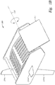
marine vibrator source 100 may be towed with a selected orientation so that the selected hydrodynamic characteristics of the components result in a desired hydrodynamic force and/or positional change of themarine vibrator source 100. The orientation may be actively or passively controllable and/or adjustable. For example, as illustrated inFigure 3A , the pitch angle ofmarine vibrator source 100 may be actively or passively controllable and/or adjustable. As illustrated,vibrational surfaces 110 may rotate 214 relative tohousing structure 115. For example,vibrational surfaces 110 may rotate 214 aboutpivot 204, which is coupled tohousing structure 115. Therotation 214 may be 360°. In some embodiments, therotation 214 may be limited to a selected range, such as no more than 45° from neutral, no more than 60° from neutral, no more than 180° from neutral, etc. Towingharness 260 may be coupled tohousing structure 115 at two, three, four, or more attachment points. Towing forces (e.g., from towing harness 260), drag forces, and/or stabilizing forces (e.g., from stability features 119) may causerotation 214 betweenvibrational surfaces 110 andhousing structure 115 to change the pitch angle of themarine vibrator source 100. The speed, magnitude, and/or direction ofrotation 214 may be controlled by steering control equipment 108 (Figure 1A ). - As another example, the roll angle of
marine vibrator source 100 may be actively or passively controllable and/or adjustable. As illustrated inFigure 3B ,housing structure 115 may rotate 212 relative to track 215. Therotation 212 may be 360°. In some embodiments, therotation 212 may be limited to a selected range, such as no more than 45° from neutral, no more than 60° from neutral, no more than 180° from neutral, etc. Towingharness 260 may be coupled to track 215 at two, three, four, or more attachment points.Housing structure 115 may be slidably coupled totrack 215. Towing forces (e.g., from towing harness 260), drag forces, and/or stabilizing forces (e.g., from stability features 119) may causerotation 212 betweenhousing structure 115 and track 215 to change the roll angle of themarine vibrator source 100. The speed, magnitude, and/or direction ofrotation 212 may be controlled by steering control equipment 108 (Figure 1A ). - As another example, the yaw angle of
marine vibrator source 100 may be actively or passively controllable and/or adjustable. As illustrated inFigure 3C , track 215 may rotate 216 relative tospindle frame 213. Therotation 216 may be 360°. In some embodiments, therotation 216 may be limited to a selected range, such as no more than 45° from neutral, no more than 60° from neutral, no more than 180° from neutral, etc. Towingharness 260 may be coupled tospindle frame 213 at two, three, four, or more attachment points.Track 215 may be rotatably coupled tospindle frame 213. Towing forces (e.g., from towing harness 260), drag forces, and/or stabilizing forces (e.g., from stability features 119) may causerotation 216 betweentrack 215 andspindle frame 213 to change the yaw angle of themarine vibrator source 100. The speed, magnitude, and/or direction ofrotation 216 may be controlled by steeringcontrol equipment 108. - As another example, the roll, pitch, and/or yaw angles of
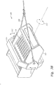
marine vibrator source 100 may be actively or passively controllable and/or adjustable with the use of a gimbal. For example, as illustrated inFigure 3D ,marine vibrator source 100 may be suspended in agimbal 270 inside of aframework 225. Towingharness 260 may be coupled toframework 225 at two, three, four, or more attachment points. Stability features, such as keel 219-k, may be coupled toframework 225. In some embodiments,framework 225 may be directly coupled to buoyancy device 130 (not shown).Gimbal 270 may allow for rotation in one, two, or three dimensions (e.g.,roll rotation 212,pitch rotation 214, and/or yaw rotation 216) betweenmarine vibrator source 100 andframework 225. The rotation in any dimension may be 360°. In some embodiments, the rotation in one or more dimensions may be limited to a selected range, such as no more than 45° from neutral, no more than 60° from neutral, no more than 180° from neutral, etc. Thus,marine vibrator source 100 may be towed with a selected orientation so that the selected hydrodynamic characteristics of the components result in a desired hydrodynamic force and/or positional change of themarine vibrator source 100. - A
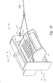
source array 220 may include one or more steerable marine geophysical sources. Thesource array 220 may be towed withmarine vibrator sources 100 having selected orientations. In some embodiments, two or moremarine vibrator sources 100 ofsource array 220 may be towed with the same selected orientation. In some embodiments, eachmarine vibrator source 100 ofsource array 220 may be towed with its own selected orientation. As illustrated inFigure 4 , threemarine vibrator sources 100 may each be suspended in aseparate gimbal 370. The threegimbals 370 may then be coupled inside of aframework 325. Towingharness 360 may be coupled toframework 325 at two, three, four, or more attachment points. Stability features, such as fins 219-f, may be coupled toframework 325. In some embodiments,framework 325 may be directly coupled to buoyancy device 130 (not shown). The threegimbals 370 may allow for independent rotation of eachmarine vibrator source 100 relative toframework 325. Independent rotation of eachmarine vibrator source 100 may allow for more robust steering control. For example, due to lever arm and/or flow/shadowing considerations, the most forwardmarine vibrator source 100 may provide gross steering adjustments, while the most aftmarine vibrator source 100 may provide fine steering adjustments.Steering control equipment 108 may provide for coordinated control of the orientation of eachmarine vibrator source 100, which may allow for simultaneous gross and fine control of roll, pitch, and/or yaw angles of thesource array 220. - As another example configuration, a
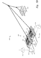
source array 320 may be towed without a framework.Figure 5A illustrates asource array 320 having four marine vibrator sources 100. Eachmarine vibrator source 100 includesvibrational surfaces 110 functionally coupled to ahousing structure 415. As illustrated, eachmarine vibrator source 100 is coupled to itshousing structure 415 so thatvibrational surfaces 110 can rotate aboutpitch angle 414 relative to thehousing structure 415. Rotation of thevibrational surfaces 110 aboutpitch angle 414 relative tohousing structure 415 may create an angle of attack against the water flow. Thehousing structures 415 are coupled together bylines 429. In some embodiments,lines 429 may be replaced and/or supplemented by bars or pipes. It should be appreciated that drag force while towing may provide sufficient rigidity tolines 429 to obviate any additional structure provided by bars or pipes. The lines 429 (or bars or pipes) may be free to rotate relative tohousing structures 415. Stability features (not shown) may be coupled to one or more of thehousing structures 415. Eachhousing structure 415 may be suspended bylines 455. For example,lines 455 may couple to a buoyancy device (not shown). Aforward housing structure 415 may be coupled to towingharness 460. Aforward housing structure 415 may have an optionalfront wing 417 on its forward side.Front wing 417 may be in addition to or in lieu of hydrodynamically-shapedforward portion 117 of the forwardmarine vibrator source 100.Front wing 417 may be fixed, controllable, adjustable, active, and/or passive. - As another example configuration,
Figure 5B illustrates asource towing system 150 for asource array 420 of twomarine vibrator sources 100 that includetail rudders 580 to provide better stability while towing. In some embodiments, thetail rudder 580 may be fixed in three dimensions relative to thehousing structure 115. In some embodiments, thetail rudder 580 may include atail fin 584 that is rotatable relative to the housing structure along ayaw angle 516. In some embodiments, the tail rudder may include atail support 582 that is rotatable relative tohousing structure 115 along apitch angle 514. Thesource towing system 150 illustrated inFigure 5B also includes an optionalforward depressor 570. - As another example configuration,
Figure 5C illustrates asource towing system 150 for a two-dimensional (2D)source array 520. Thesource array 520 includes four marine vibrator sources 100. Thesource towing system 150 includes aframework 525. Stability features, such as keel 219-k, may be coupled toframework 525. The2D source array 520 is buoyantly supported by a pair ofbuoyancy devices 130. Theframework 525 is fixed tobuoyancy devices 130. Portions of eachmarine vibrator source 100 may rotate relative toframework 525, independently or collectively. For example, thevibrational surface 110 of one of themarine vibrator sources 100 may rotate 714 relative toframework 525. Therotation 714 may change the pitch angle of thesource array 520. Thus,marine vibrator source 100 may be steerable by adjusting one or more steering parameters of anymarine vibrator sources 100 in thesource array - As would be understood by one of ordinary skill in the art with the benefit of this disclosure, a geophysical source can often be approximated as a point source. When the size of the geophysical source is negligible relative to other length scales in the survey, a point-source approximation may be sufficient. Consequently, energy interactions at the ocean floor, water surface, and/or geophysical sensor array may be independent of the orientation of the source components - such as the vibrational surfaces 110. Thus, even during data acquisition,
marine vibrator source 100 may be towed with a selected orientation so that the selected hydrodynamic characteristics of the components result in a desired hydrodynamic force and/or positional change of themarine vibrator source 100. - In some embodiments, the
marine vibrator source 100 may include pressure compensation features. For example, the internal pressure of themarine vibrator source 100 may be adjusted to compensate for changes in external pressure. Changes in external pressure may be due to water depth. Changes in external pressure may also be due to speed of themarine vibrator source 100 through the water. In some embodiments, information from thesteering control equipment 108, such as water speed and/or depth, may be used to adjust the internal pressure compensation of themarine vibrator source 100. -
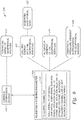
Figure 6 illustrates amethod 600 of steering a geophysical source according to embodiments disclosed herein. Themethod 600 begins atstep 610, wherein the geophysical source is towed through a body of water. For example, the geophysical source may be towed by a survey vessel. The survey vessel may also tow geophysical sensors on one or more streamers, and/or another vessel may tow geophysical sensors on one or more streamers. In some embodiments, themethod 600 may also includestep 615, wherein the geophysical source is towed in an array of geophysical sources. - The
method 600 continues atstep 620, wherein a steering parameter is adjusted while towing the geophysical source. Example steering parameters are shown at 621. The steering parameter may include, for example, at least one of the roll angle of the geophysical source, the pitch angle of the geophysical source, the yaw angle of the geophysical source, and/or the buoyancy of the geophysical source. As another example, when the geophysical source is a marine vibrator source, the steering parameter may include at least one of the surface shape of at least one vibrational surface of the marine vibrator source, the rotation between at least one vibrational surface and a front wing of the marine vibrator source, and/or the rotation between at least one vibrational surface and a stability feature, of the marine vibrator source. As another example, when the geophysical source is towed in an array of geophysical sources, the steering parameter may include at least one steering parameter of any of the other geophysical sources in the source array. - In some embodiments, the
method 600 may also includestep 622, wherein the geophysical source emits energy as part of a geophysical survey. For example, the energy may be emitted while the geophysical source is towed through the water and/or while the steering parameter is adjusted. In some embodiments, themethod 600 also includesstep 623, wherein geophysical data is acquired as part of a geophysical survey. For example, geophysical sensors may collect data reflecting the energy emitted by the geophysical source, possibly following interaction with a subsurface formation. In accordance with a number of embodiments of the present disclosure, a geophysical data product may be produced from the geophysical data. For example, geophysical data may be processed to produce a seismic image. The seismic image may be recorded on a non-transitory, tangible computer-readable medium, thereby producing a geophysical data product. The geophysical data product may be produced by processing the geophysical data offshore (i.e. by equipment on a vessel) or onshore (i.e. at a facility on land) either within the United States or in another country. If the geophysical data product is produced offshore or in another country, it may be imported onshore to a facility in the United States. In some instances, once onshore in the United States, geophysical analysis, including further data processing, may be performed on the geophysical data product. In some instances, geophysical analysis may be performed on the geophysical data product offshore. - In some embodiments, the
method 600 may also includestep 624, wherein a heading of the geophysical source is altered. For example, when the roll angle is neutral, and when the steering parameter is a pitch angle of the geophysical source, adjusting the steering parameter may alter the vertical heading of the geophysical source. As another example, when the roll angle is neutral, and when the steering parameter is a yaw angle of the geophysical source, adjusting the steering parameter may alter the lateral heading of the geophysical source. A person of ordinary skill in the art with the benefit of this disclosure would understand a wide variety of steering parameter adjustments that, alone or in combination, alter at least one of the vertical heading and the lateral heading of the geophysical source. - In some embodiments, the
method 600 may also includestep 626, wherein a pressure gradient is created in the water surrounding the geophysical source. For example, the surface shape of the geophysical source may be hydrofoil-shaped to create a pressure gradient and/or provide selected hydrodynamic force while the geophysical source is towed through the water. As another example, when the geophysical source is a marine vibrator, the vibrational surfaces may vibrate through a range of surface shapes, and a subset of the surface shapes may create a pressure gradient and/or provide selected hydrodynamic force while the marine vibrator source is towed through the water. As another example, opposing vibrational surfaces of the same marine vibrator source may not mirror one another, but rather vibrate through different ranges of surface shapes that may together create a pressure gradient and/or provide enhanced hydrodynamic force while the marine vibrator source is towed through the water. A person of ordinary skill in the art with the benefit of this disclosure would understand a wide variety of steering parameter adjustments that, alone or in combination, create a pressure gradient in the water surrounding the geophysical source. - In an embodiment, a method includes towing a first geophysical source through a body of water; and adjusting a first steering parameter of the first geophysical source while towing the first geophysical source.
- In one or more embodiments disclosed herein, the first steering parameter includes at least one of a roll angle of the first geophysical source, a pitch angle of the first geophysical source, a yaw angle of the first geophysical source, a surface shape of a vibrational surface of the first geophysical source, a rotation between the vibrational surface and a front wing of the first geophysical source, a rotation between the vibrational surface and a stability feature of the first geophysical source, and a buoyancy of the first geophysical source.
- In one or more embodiments disclosed herein, the stability feature includes at least one of a fin, a rudder, and a keel.
- In one or more embodiments disclosed herein, a method also includes emitting energy with the first geophysical source while adjusting the first steering parameter.
- In one or more embodiments disclosed herein, a method also includes acquiring geophysical data while adjusting the first steering parameter.
- In one or more embodiments disclosed herein, a method also includes processing the geophysical data to produce a seismic image.
- In one or more embodiments disclosed herein, a method also includes recording the seismic image on a non-transitory, tangible computer-readable medium, thereby creating a geophysical data product.
- In one or more embodiments disclosed herein, a method also includes performing geophysical analysis onshore on the geophysical data product.
- In one or more embodiments disclosed herein, the first geophysical source is a marine vibrator source.
- In one or more embodiments disclosed herein, a method also includes towing the first geophysical source in a source array with a plurality of other geophysical sources.
- In one or more embodiments disclosed herein, a method also includes adjusting a steering parameter of at least one of the plurality of other geophysical sources while towing the source array.
- In one or more embodiments disclosed herein, a method also includes adjusting a steering parameter of each of the plurality of other geophysical sources while towing the source array.
- In one or more embodiments disclosed herein, a method also includes towing a second geophysical source of the source array with a second pitch angle, and towing a third geophysical source of the source array with a third pitch angle, wherein the second pitch angle is different from the third pitch angle.
- In one or more embodiments disclosed herein, a method also includes altering at least one of a lateral heading and a vertical heading of the first geophysical source.
- In one or more embodiments disclosed herein, a method also includes creating a pressure gradient in the body of water surrounding the first geophysical source.
- In one or more embodiments disclosed herein, a method also includes analyzing steering data; and controlling the adjusting the first steering parameter in response to the analyzing.
- In one or more embodiments disclosed herein, a method also includes towing a sensor streamer through the body of water; and steering the first geophysical source to be under the sensor streamer.
- In an embodiment, a geophysical source steering system includes a first marine vibrator source having a first housing structure; a first vibrational surface functionally coupled to the first housing structure such that at least a portion of the first vibrational surface can vibrate relative to the first housing structure; and first steering control equipment.
- In one or more embodiments disclosed herein, the first vibrational surface is hydrofoil-shaped.
- In one or more embodiments disclosed herein, the first marine vibrator source further comprises a second vibrational surface, wherein the second vibrational surface has a greater curvature than the first vibrational surface.
- In one or more embodiments disclosed herein, the first vibrational surface can rotate through a first pitch angle relative to the first housing structure.
- In one or more embodiments disclosed herein, a system also includes a first track, wherein the first vibrational surface can rotate through a first roll angle relative to the first track.
- In one or more embodiments disclosed herein, a system also includes a first spindle frame, wherein the first vibrational surface can rotate through a first yaw angle relative to the first spindle frame.
- In one or more embodiments disclosed herein, a system also includes g a stability feature that includes at least one of a fin, a rudder, and a keel.
- In one or more embodiments disclosed herein, a system also includes a framework; and a first gimbal suspending the first marine vibrator source inside the framework.
- In one or more embodiments disclosed herein, the first gimbal allows for rotation of the first marine vibrator source in at least one dimension relative to the framework.
- In one or more embodiments disclosed herein, a system also includes a second marine vibrator suspended in a second gimbal inside the framework.
- In one or more embodiments disclosed herein, a system also includes a second marine vibrator having a second housing structure; a second vibrational surface functionally coupled to the second housing structure such that at least a portion of the second vibrational surface can vibrate relative to the second housing structure; and a coupling between the first housing structure and the second housing structure.
- In one or more embodiments disclosed herein, the first vibrational surface can rotate through a first pitch angle relative to the first housing structure; and the second vibrational surface can rotate through a second pitch angle relative to the second housing structure.
- In one or more embodiments disclosed herein, the coupling is free to rotate relative to the first housing structure and the second housing structure.
- In one or more embodiments disclosed herein, the first marine vibrator source further comprises a tail rudder that can rotate relative to the first housing structure.
- In one or more embodiments disclosed herein, a system also includes a forward depressor.
- In one or more embodiments disclosed herein, a system also includes a plurality of marine vibrator sources disposed in a two-dimensional source array.
- In one or more embodiments disclosed herein, a system also includes a framework coupled to a source towing system, wherein the steering control equipment includes a rotational actuator between the first vibrational surface and the framework.
- While the foregoing is directed to embodiments of the present invention, other and further embodiments of the invention may be devised without departing from the basic scope thereof, and the scope thereof is determined by the claims that follow.
Claims (19)
- A method comprising:towing a first geophysical source through a body of water; andadjusting a first steering parameter of the first geophysical source while towing the first geophysical source, wherein the first steering parameter includes at least one of a roll angle of the first geophysical source, a pitch angle of the first geophysical source, a yaw angle of the first geophysical source, a surface shape of a vibrational surface of the first geophysical source, a rotation between the vibrational surface and a front wing of the first geophysical source, a rotation between the vibrational surface and a stability feature of the first geophysical source, and a buoyancy of the first geophysical source.
- The method of claim 1, wherein the stability feature includes at least one of a fin, a rudder, and a keel.
- The method of claim 1 or 2, further comprising emitting energy with the first geophysical source while adjusting the first steering parameter.
- The method of any of claims 1 to 3, further comprising:acquiring geophysical data while adjusting the first steering parameter;processing the geophysical data to produce a seismic image; andrecording the seismic image on a non-transitory, tangible computer-readable medium, thereby creating a geophysical data product, and preferably further comprising:towing a second geophysical source of the source array with a second pitch angle, andtowing a third geophysical source of the source array with a third pitch angle, wherein the second pitch angle is different from the third pitch angle.
- The method of any of the preceding claims, further comprising towing the first geophysical source in a source array with a plurality of other geophysical sources.
- The method of claim 5, further comprising adjusting a steering parameter of at least one of the plurality of other geophysical sources while towing the source array, or further comprising adjusting a steering parameter of each of the plurality of other geophysical sources while towing the source array.
- The method of any of the preceding claims, further comprising:analyzing steering data; andcontrolling the adjusting the first steering parameter in response to the analyzing.
- The method of any of the preceding claims, further comprising:towing a sensor streamer through the body of water; andsteering the first geophysical source to be under the sensor streamer.
- A geophysical source steering system comprising:a first marine vibrator source comprising:a first housing structure;a first vibrational surface functionally coupled to the first housing structure such that at least a portion of the first vibrational surface can vibrate relative to the first housing structure; andfirst steering control equipment.
- The system of claim 9, whereina) the first vibrational surface is hydrofoil-shaped, and/orb) wherein the first marine vibrator source further comprises a second vibrational surface, wherein the second vibrational surface has a greater curvature than the first vibrational surface, and/orc) wherein the first vibrational surface can rotate through a first pitch angle relative to the first housing structure.
- The system of claim 9 or claim 10, further comprising a first track, wherein the first vibrational surface can rotate through a first roll angle relative to the first track, and/or further comprising a first spindle frame, wherein the first vibrational surface can rotate through a first yaw angle relative to the first spindle frame.
- The system of any of claims 9 to 11, further comprising a stability feature that includes at least one of a fin, a rudder, and a keel.
- The system of any of claims 9 to 12, further comprising:a framework; anda first gimbal suspending the first marine vibrator source inside the framework, wherein preferably the first gimbal allows for rotation of the first marine vibrator source in at least one dimension relative to the framework, and wherein preferably the system further comprises a second marine vibrator suspended in a second gimbal inside the framework.
- The system of any of claims 9 to 13, further comprising:a second marine vibrator comprising:a second housing structure;a second vibrational surface functionally coupled to the second housing structure such that at least a portion of the second vibrational surface can vibrate relative to the second housing structure; anda coupling between the first housing structure and the second housing structure.
- The system of claim 14, wherein the first vibrational surface can rotate through a first pitch angle relative to the first housing structure; and the second vibrational surface can rotate through a second pitch angle relative to the second housing structure.
- The system of claim14 or claim 15, wherein the coupling is free to rotate relative to the first housing structure and the second housing structure.
- The system of any of claims 9 to 16, wherein the first marine vibrator source further comprises a tail rudder that can rotate relative to the first housing structure.
- The system of any of claims 9 to 17, further comprising a plurality of marine vibrator sources disposed in a two-dimensional source array.
- The system of any of claims 9 to 18, further comprising a framework coupled to a source towing system, wherein the steering control equipment includes a rotational actuator between the first vibrational surface and the framework.
Applications Claiming Priority (2)
| Application Number | Priority Date | Filing Date | Title |
|---|---|---|---|
| US201662433315P | 2016-12-13 | 2016-12-13 | |
| US15/792,296 US10670760B2 (en) | 2016-12-13 | 2017-10-24 | Steerable marine geophysical source |
Publications (2)
| Publication Number | Publication Date |
|---|---|
| EP3336585A1 true EP3336585A1 (en) | 2018-06-20 |
| EP3336585B1 EP3336585B1 (en) | 2021-08-18 |
Family
ID=60673327
Family Applications (1)
| Application Number | Title | Priority Date | Filing Date |
|---|---|---|---|
| EP17206894.2A Active EP3336585B1 (en) | 2016-12-13 | 2017-12-13 | Steerable marine geophysical source |
Country Status (2)
| Country | Link |
|---|---|
| US (1) | US10670760B2 (en) |
| EP (1) | EP3336585B1 (en) |
Families Citing this family (1)
| Publication number | Priority date | Publication date | Assignee | Title |
|---|---|---|---|---|
| US11027806B2 (en) * | 2018-12-21 | 2021-06-08 | Pgs Geophysical As | Towed body with foiled depressor |
Citations (5)
| Publication number | Priority date | Publication date | Assignee | Title |
|---|---|---|---|---|
| US6230840B1 (en) * | 1998-10-16 | 2001-05-15 | Western Atlas International, Inc. | Marine vibrator |
| US20060176774A1 (en) * | 2005-02-10 | 2006-08-10 | Rune Toennessen | Apparatus and methods for controlling position of marine seismic sources |
| EP2764929A2 (en) * | 2013-02-08 | 2014-08-13 | PGS Geophysical AS | Marine seismic vibrators and methods of use |
| US20150234072A1 (en) * | 2012-08-13 | 2015-08-20 | Applied Physical Sciences Corp. | Coherent Sound Source for Marine Seismic Surveys |
| US20160223696A1 (en) * | 2015-02-02 | 2016-08-04 | Cgg Services Sa | Deep towed seismic source string |
Family Cites Families (5)
| Publication number | Priority date | Publication date | Assignee | Title |
|---|---|---|---|---|
| GB2400662B (en) | 2003-04-15 | 2006-08-09 | Westerngeco Seismic Holdings | Active steering for marine seismic sources |
| US7426438B1 (en) * | 2007-03-16 | 2008-09-16 | Westerngeco L.L.C. | Technique to provide seismic data-based products |
| US9535182B2 (en) | 2009-03-09 | 2017-01-03 | Ion Geophysical Corporation | Marine seismic surveying with towed components below water surface |
| US8570829B2 (en) | 2009-12-22 | 2013-10-29 | Pgs Geophysical As | Depth steerable seismic source array |
| US9823371B2 (en) | 2014-09-02 | 2017-11-21 | Pgs Geophysical As | Methods and systems for towing acoustic source sub-arrays |
-
2017
- 2017-10-24 US US15/792,296 patent/US10670760B2/en active Active
- 2017-12-13 EP EP17206894.2A patent/EP3336585B1/en active Active
Patent Citations (5)
| Publication number | Priority date | Publication date | Assignee | Title |
|---|---|---|---|---|
| US6230840B1 (en) * | 1998-10-16 | 2001-05-15 | Western Atlas International, Inc. | Marine vibrator |
| US20060176774A1 (en) * | 2005-02-10 | 2006-08-10 | Rune Toennessen | Apparatus and methods for controlling position of marine seismic sources |
| US20150234072A1 (en) * | 2012-08-13 | 2015-08-20 | Applied Physical Sciences Corp. | Coherent Sound Source for Marine Seismic Surveys |
| EP2764929A2 (en) * | 2013-02-08 | 2014-08-13 | PGS Geophysical AS | Marine seismic vibrators and methods of use |
| US20160223696A1 (en) * | 2015-02-02 | 2016-08-04 | Cgg Services Sa | Deep towed seismic source string |
Also Published As
| Publication number | Publication date |
|---|---|
| BR102017026692A2 (en) | 2018-08-14 |
| US10670760B2 (en) | 2020-06-02 |
| US20180164459A1 (en) | 2018-06-14 |
| EP3336585B1 (en) | 2021-08-18 |
Similar Documents
| Publication | Publication Date | Title |
|---|---|---|
| US7660191B2 (en) | Methods and apparatus for acquisition of marine seismic data | |
| RU2451309C2 (en) | Seabed monitoring seismic cable | |
| US7450467B2 (en) | Apparatus and methods for seismic streamer positioning | |
| US10248886B2 (en) | System and method for underwater distance measurement | |
| GB2436457A (en) | Deriving the shape of marine seismic cables from measured characteristics of steering devices | |
| US11325680B2 (en) | Adjustable buoyancy foil | |
| CN108027449B (en) | Towed seismic node | |
| US20100135112A1 (en) | Methods and Apparatus for Acquisition of Marine Seismic Data | |
| MX2009000215A (en) | Method and system of underwater acoustic positioning of seismic streamers based on modulated acoustic signals. | |
| GB2499397A (en) | Positioning towed underwater survey apparatus | |
| NO345753B1 (en) | Method and device for seismic prospecting of the subsoil under the seabed using two drones | |
| EP2639601A2 (en) | Steering submersible float for seismic sources and related methods | |
| US9494429B2 (en) | Marine streamer inertial navigating drag body | |
| US20050279268A1 (en) | Steerable hydrofoil | |
| US10114136B2 (en) | Streamer equipment tension control | |
| US10670760B2 (en) | Steerable marine geophysical source | |
| EP3370092B1 (en) | System for source towing at depth | |
| AU2014201399B2 (en) | Wing for wide tow of geophysical survey sources | |
| BR102017026692B1 (en) | MARINE GEOPHYSICAL SOURCE TRACKING SYSTEM AND GUIDANCE METHOD |
Legal Events
| Date | Code | Title | Description |
|---|---|---|---|
| PUAI | Public reference made under article 153(3) epc to a published international application that has entered the european phase |
Free format text: ORIGINAL CODE: 0009012 |
|
| STAA | Information on the status of an ep patent application or granted ep patent |
Free format text: STATUS: THE APPLICATION HAS BEEN PUBLISHED |
|
| AK | Designated contracting states |
Kind code of ref document: A1 Designated state(s): AL AT BE BG CH CY CZ DE DK EE ES FI FR GB GR HR HU IE IS IT LI LT LU LV MC MK MT NL NO PL PT RO RS SE SI SK SM TR |
|
| AX | Request for extension of the european patent |
Extension state: BA ME |
|
| STAA | Information on the status of an ep patent application or granted ep patent |
Free format text: STATUS: REQUEST FOR EXAMINATION WAS MADE |
|
| 17P | Request for examination filed |
Effective date: 20181219 |
|
| RBV | Designated contracting states (corrected) |
Designated state(s): AL AT BE BG CH CY CZ DE DK EE ES FI FR GB GR HR HU IE IS IT LI LT LU LV MC MK MT NL NO PL PT RO RS SE SI SK SM TR |
|
| STAA | Information on the status of an ep patent application or granted ep patent |
Free format text: STATUS: REQUEST FOR EXAMINATION WAS MADE |
|
| GRAP | Despatch of communication of intention to grant a patent |
Free format text: ORIGINAL CODE: EPIDOSNIGR1 |
|
| STAA | Information on the status of an ep patent application or granted ep patent |
Free format text: STATUS: GRANT OF PATENT IS INTENDED |
|
| INTG | Intention to grant announced |
Effective date: 20210318 |
|
| GRAS | Grant fee paid |
Free format text: ORIGINAL CODE: EPIDOSNIGR3 |
|
| GRAA | (expected) grant |
Free format text: ORIGINAL CODE: 0009210 |
|
| STAA | Information on the status of an ep patent application or granted ep patent |
Free format text: STATUS: THE PATENT HAS BEEN GRANTED |
|
| AK | Designated contracting states |
Kind code of ref document: B1 Designated state(s): AL AT BE BG CH CY CZ DE DK EE ES FI FR GB GR HR HU IE IS IT LI LT LU LV MC MK MT NL NO PL PT RO RS SE SI SK SM TR |
|
| REG | Reference to a national code |
Ref country code: GB Ref legal event code: FG4D |
|
| REG | Reference to a national code |
Ref country code: CH Ref legal event code: EP |
|
| REG | Reference to a national code |
Ref country code: DE Ref legal event code: R096 Ref document number: 602017044195 Country of ref document: DE |
|
| REG | Reference to a national code |
Ref country code: IE Ref legal event code: FG4D Ref country code: AT Ref legal event code: REF Ref document number: 1422134 Country of ref document: AT Kind code of ref document: T Effective date: 20210915 |
|
| REG | Reference to a national code |
Ref country code: LT Ref legal event code: MG9D |
|
| REG | Reference to a national code |
Ref country code: NL Ref legal event code: MP Effective date: 20210818 |
|
| REG | Reference to a national code |
Ref country code: AT Ref legal event code: MK05 Ref document number: 1422134 Country of ref document: AT Kind code of ref document: T Effective date: 20210818 |
|
| PG25 | Lapsed in a contracting state [announced via postgrant information from national office to epo] |
Ref country code: NO Free format text: LAPSE BECAUSE OF FAILURE TO SUBMIT A TRANSLATION OF THE DESCRIPTION OR TO PAY THE FEE WITHIN THE PRESCRIBED TIME-LIMIT Effective date: 20211118 Ref country code: PT Free format text: LAPSE BECAUSE OF FAILURE TO SUBMIT A TRANSLATION OF THE DESCRIPTION OR TO PAY THE FEE WITHIN THE PRESCRIBED TIME-LIMIT Effective date: 20211220 Ref country code: FI Free format text: LAPSE BECAUSE OF FAILURE TO SUBMIT A TRANSLATION OF THE DESCRIPTION OR TO PAY THE FEE WITHIN THE PRESCRIBED TIME-LIMIT Effective date: 20210818 Ref country code: ES Free format text: LAPSE BECAUSE OF FAILURE TO SUBMIT A TRANSLATION OF THE DESCRIPTION OR TO PAY THE FEE WITHIN THE PRESCRIBED TIME-LIMIT Effective date: 20210818 Ref country code: AT Free format text: LAPSE BECAUSE OF FAILURE TO SUBMIT A TRANSLATION OF THE DESCRIPTION OR TO PAY THE FEE WITHIN THE PRESCRIBED TIME-LIMIT Effective date: 20210818 Ref country code: BG Free format text: LAPSE BECAUSE OF FAILURE TO SUBMIT A TRANSLATION OF THE DESCRIPTION OR TO PAY THE FEE WITHIN THE PRESCRIBED TIME-LIMIT Effective date: 20211118 Ref country code: LT Free format text: LAPSE BECAUSE OF FAILURE TO SUBMIT A TRANSLATION OF THE DESCRIPTION OR TO PAY THE FEE WITHIN THE PRESCRIBED TIME-LIMIT Effective date: 20210818 Ref country code: RS Free format text: LAPSE BECAUSE OF FAILURE TO SUBMIT A TRANSLATION OF THE DESCRIPTION OR TO PAY THE FEE WITHIN THE PRESCRIBED TIME-LIMIT Effective date: 20210818 Ref country code: SE Free format text: LAPSE BECAUSE OF FAILURE TO SUBMIT A TRANSLATION OF THE DESCRIPTION OR TO PAY THE FEE WITHIN THE PRESCRIBED TIME-LIMIT Effective date: 20210818 Ref country code: HR Free format text: LAPSE BECAUSE OF FAILURE TO SUBMIT A TRANSLATION OF THE DESCRIPTION OR TO PAY THE FEE WITHIN THE PRESCRIBED TIME-LIMIT Effective date: 20210818 |
|
| PG25 | Lapsed in a contracting state [announced via postgrant information from national office to epo] |
Ref country code: PL Free format text: LAPSE BECAUSE OF FAILURE TO SUBMIT A TRANSLATION OF THE DESCRIPTION OR TO PAY THE FEE WITHIN THE PRESCRIBED TIME-LIMIT Effective date: 20210818 Ref country code: LV Free format text: LAPSE BECAUSE OF FAILURE TO SUBMIT A TRANSLATION OF THE DESCRIPTION OR TO PAY THE FEE WITHIN THE PRESCRIBED TIME-LIMIT Effective date: 20210818 Ref country code: GR Free format text: LAPSE BECAUSE OF FAILURE TO SUBMIT A TRANSLATION OF THE DESCRIPTION OR TO PAY THE FEE WITHIN THE PRESCRIBED TIME-LIMIT Effective date: 20211119 |
|
| PG25 | Lapsed in a contracting state [announced via postgrant information from national office to epo] |
Ref country code: NL Free format text: LAPSE BECAUSE OF FAILURE TO SUBMIT A TRANSLATION OF THE DESCRIPTION OR TO PAY THE FEE WITHIN THE PRESCRIBED TIME-LIMIT Effective date: 20210818 |
|
| PG25 | Lapsed in a contracting state [announced via postgrant information from national office to epo] |
Ref country code: DK Free format text: LAPSE BECAUSE OF FAILURE TO SUBMIT A TRANSLATION OF THE DESCRIPTION OR TO PAY THE FEE WITHIN THE PRESCRIBED TIME-LIMIT Effective date: 20210818 |
|
| REG | Reference to a national code |
Ref country code: DE Ref legal event code: R097 Ref document number: 602017044195 Country of ref document: DE |
|
| PG25 | Lapsed in a contracting state [announced via postgrant information from national office to epo] |
Ref country code: SM Free format text: LAPSE BECAUSE OF FAILURE TO SUBMIT A TRANSLATION OF THE DESCRIPTION OR TO PAY THE FEE WITHIN THE PRESCRIBED TIME-LIMIT Effective date: 20210818 Ref country code: SK Free format text: LAPSE BECAUSE OF FAILURE TO SUBMIT A TRANSLATION OF THE DESCRIPTION OR TO PAY THE FEE WITHIN THE PRESCRIBED TIME-LIMIT Effective date: 20210818 Ref country code: RO Free format text: LAPSE BECAUSE OF FAILURE TO SUBMIT A TRANSLATION OF THE DESCRIPTION OR TO PAY THE FEE WITHIN THE PRESCRIBED TIME-LIMIT Effective date: 20210818 Ref country code: EE Free format text: LAPSE BECAUSE OF FAILURE TO SUBMIT A TRANSLATION OF THE DESCRIPTION OR TO PAY THE FEE WITHIN THE PRESCRIBED TIME-LIMIT Effective date: 20210818 Ref country code: CZ Free format text: LAPSE BECAUSE OF FAILURE TO SUBMIT A TRANSLATION OF THE DESCRIPTION OR TO PAY THE FEE WITHIN THE PRESCRIBED TIME-LIMIT Effective date: 20210818 Ref country code: AL Free format text: LAPSE BECAUSE OF FAILURE TO SUBMIT A TRANSLATION OF THE DESCRIPTION OR TO PAY THE FEE WITHIN THE PRESCRIBED TIME-LIMIT Effective date: 20210818 |
|
| PLBE | No opposition filed within time limit |
Free format text: ORIGINAL CODE: 0009261 |
|
| STAA | Information on the status of an ep patent application or granted ep patent |
Free format text: STATUS: NO OPPOSITION FILED WITHIN TIME LIMIT |
|
| REG | Reference to a national code |
Ref country code: DE Ref legal event code: R119 Ref document number: 602017044195 Country of ref document: DE |
|
| 26N | No opposition filed |
Effective date: 20220519 |
|
| PG25 | Lapsed in a contracting state [announced via postgrant information from national office to epo] |
Ref country code: MC Free format text: LAPSE BECAUSE OF FAILURE TO SUBMIT A TRANSLATION OF THE DESCRIPTION OR TO PAY THE FEE WITHIN THE PRESCRIBED TIME-LIMIT Effective date: 20210818 Ref country code: IT Free format text: LAPSE BECAUSE OF FAILURE TO SUBMIT A TRANSLATION OF THE DESCRIPTION OR TO PAY THE FEE WITHIN THE PRESCRIBED TIME-LIMIT Effective date: 20210818 |
|
| REG | Reference to a national code |
Ref country code: CH Ref legal event code: PL |
|
| PG25 | Lapsed in a contracting state [announced via postgrant information from national office to epo] |
Ref country code: SI Free format text: LAPSE BECAUSE OF FAILURE TO SUBMIT A TRANSLATION OF THE DESCRIPTION OR TO PAY THE FEE WITHIN THE PRESCRIBED TIME-LIMIT Effective date: 20210818 |
|
| REG | Reference to a national code |
Ref country code: BE Ref legal event code: MM Effective date: 20211231 |
|
| PG25 | Lapsed in a contracting state [announced via postgrant information from national office to epo] |
Ref country code: LU Free format text: LAPSE BECAUSE OF NON-PAYMENT OF DUE FEES Effective date: 20211213 Ref country code: IE Free format text: LAPSE BECAUSE OF NON-PAYMENT OF DUE FEES Effective date: 20211213 Ref country code: DE Free format text: LAPSE BECAUSE OF NON-PAYMENT OF DUE FEES Effective date: 20220701 |
|
| PG25 | Lapsed in a contracting state [announced via postgrant information from national office to epo] |
Ref country code: BE Free format text: LAPSE BECAUSE OF NON-PAYMENT OF DUE FEES Effective date: 20211231 |
|
| PG25 | Lapsed in a contracting state [announced via postgrant information from national office to epo] |
Ref country code: LI Free format text: LAPSE BECAUSE OF NON-PAYMENT OF DUE FEES Effective date: 20211231 Ref country code: CH Free format text: LAPSE BECAUSE OF NON-PAYMENT OF DUE FEES Effective date: 20211231 |
|
| PG25 | Lapsed in a contracting state [announced via postgrant information from national office to epo] |
Ref country code: HU Free format text: LAPSE BECAUSE OF FAILURE TO SUBMIT A TRANSLATION OF THE DESCRIPTION OR TO PAY THE FEE WITHIN THE PRESCRIBED TIME-LIMIT; INVALID AB INITIO Effective date: 20171213 |
|
| P01 | Opt-out of the competence of the unified patent court (upc) registered |
Effective date: 20230516 |
|
| PG25 | Lapsed in a contracting state [announced via postgrant information from national office to epo] |
Ref country code: CY Free format text: LAPSE BECAUSE OF FAILURE TO SUBMIT A TRANSLATION OF THE DESCRIPTION OR TO PAY THE FEE WITHIN THE PRESCRIBED TIME-LIMIT Effective date: 20210818 |
|
| PGFP | Annual fee paid to national office [announced via postgrant information from national office to epo] |
Ref country code: GB Payment date: 20231227 Year of fee payment: 7 |
|
| PGFP | Annual fee paid to national office [announced via postgrant information from national office to epo] |
Ref country code: FR Payment date: 20231227 Year of fee payment: 7 |
|
| PG25 | Lapsed in a contracting state [announced via postgrant information from national office to epo] |
Ref country code: MK Free format text: LAPSE BECAUSE OF FAILURE TO SUBMIT A TRANSLATION OF THE DESCRIPTION OR TO PAY THE FEE WITHIN THE PRESCRIBED TIME-LIMIT Effective date: 20210818 |