EP3336582B1 - Vision sensing compensation - Google Patents
Vision sensing compensation Download PDFInfo
- Publication number
- EP3336582B1 EP3336582B1 EP17203382.1A EP17203382A EP3336582B1 EP 3336582 B1 EP3336582 B1 EP 3336582B1 EP 17203382 A EP17203382 A EP 17203382A EP 3336582 B1 EP3336582 B1 EP 3336582B1
- Authority
- EP
- European Patent Office
- Prior art keywords
- vehicle
- host
- interest
- discontinuity
- area
- Prior art date
- Legal status (The legal status is an assumption and is not a legal conclusion. Google has not performed a legal analysis and makes no representation as to the accuracy of the status listed.)
- Active
Links
- 238000004891 communication Methods 0.000 claims description 3
- 238000000034 method Methods 0.000 description 3
- 230000004044 response Effects 0.000 description 3
- 230000008859 change Effects 0.000 description 2
- 230000009466 transformation Effects 0.000 description 2
- 230000001052 transient effect Effects 0.000 description 2
- 201000004569 Blindness Diseases 0.000 description 1
- 230000009286 beneficial effect Effects 0.000 description 1
- 238000005516 engineering process Methods 0.000 description 1
- 230000006870 function Effects 0.000 description 1
- 230000006872 improvement Effects 0.000 description 1
- 208000018769 loss of vision Diseases 0.000 description 1
- 231100000864 loss of vision Toxicity 0.000 description 1
- 238000002310 reflectometry Methods 0.000 description 1
- 238000005096 rolling process Methods 0.000 description 1
- 239000000725 suspension Substances 0.000 description 1
- 230000007704 transition Effects 0.000 description 1
- 230000004393 visual impairment Effects 0.000 description 1
Images


Classifications
-
- B—PERFORMING OPERATIONS; TRANSPORTING
- B60—VEHICLES IN GENERAL
- B60W—CONJOINT CONTROL OF VEHICLE SUB-UNITS OF DIFFERENT TYPE OR DIFFERENT FUNCTION; CONTROL SYSTEMS SPECIALLY ADAPTED FOR HYBRID VEHICLES; ROAD VEHICLE DRIVE CONTROL SYSTEMS FOR PURPOSES NOT RELATED TO THE CONTROL OF A PARTICULAR SUB-UNIT
- B60W30/00—Purposes of road vehicle drive control systems not related to the control of a particular sub-unit, e.g. of systems using conjoint control of vehicle sub-units
- B60W30/10—Path keeping
- B60W30/12—Lane keeping
-
- B—PERFORMING OPERATIONS; TRANSPORTING
- B60—VEHICLES IN GENERAL
- B60T—VEHICLE BRAKE CONTROL SYSTEMS OR PARTS THEREOF; BRAKE CONTROL SYSTEMS OR PARTS THEREOF, IN GENERAL; ARRANGEMENT OF BRAKING ELEMENTS ON VEHICLES IN GENERAL; PORTABLE DEVICES FOR PREVENTING UNWANTED MOVEMENT OF VEHICLES; VEHICLE MODIFICATIONS TO FACILITATE COOLING OF BRAKES
- B60T7/00—Brake-action initiating means
- B60T7/12—Brake-action initiating means for automatic initiation; for initiation not subject to will of driver or passenger
-
- G—PHYSICS
- G01—MEASURING; TESTING
- G01S—RADIO DIRECTION-FINDING; RADIO NAVIGATION; DETERMINING DISTANCE OR VELOCITY BY USE OF RADIO WAVES; LOCATING OR PRESENCE-DETECTING BY USE OF THE REFLECTION OR RERADIATION OF RADIO WAVES; ANALOGOUS ARRANGEMENTS USING OTHER WAVES
- G01S17/00—Systems using the reflection or reradiation of electromagnetic waves other than radio waves, e.g. lidar systems
- G01S17/86—Combinations of lidar systems with systems other than lidar, radar or sonar, e.g. with direction finders
-
- G—PHYSICS
- G01—MEASURING; TESTING
- G01S—RADIO DIRECTION-FINDING; RADIO NAVIGATION; DETERMINING DISTANCE OR VELOCITY BY USE OF RADIO WAVES; LOCATING OR PRESENCE-DETECTING BY USE OF THE REFLECTION OR RERADIATION OF RADIO WAVES; ANALOGOUS ARRANGEMENTS USING OTHER WAVES
- G01S17/00—Systems using the reflection or reradiation of electromagnetic waves other than radio waves, e.g. lidar systems
- G01S17/88—Lidar systems specially adapted for specific applications
- G01S17/93—Lidar systems specially adapted for specific applications for anti-collision purposes
- G01S17/931—Lidar systems specially adapted for specific applications for anti-collision purposes of land vehicles
-
- G—PHYSICS
- G06—COMPUTING; CALCULATING OR COUNTING
- G06V—IMAGE OR VIDEO RECOGNITION OR UNDERSTANDING
- G06V10/00—Arrangements for image or video recognition or understanding
- G06V10/20—Image preprocessing
- G06V10/25—Determination of region of interest [ROI] or a volume of interest [VOI]
-
- G—PHYSICS
- G06—COMPUTING; CALCULATING OR COUNTING
- G06V—IMAGE OR VIDEO RECOGNITION OR UNDERSTANDING
- G06V20/00—Scenes; Scene-specific elements
- G06V20/50—Context or environment of the image
- G06V20/56—Context or environment of the image exterior to a vehicle by using sensors mounted on the vehicle
- G06V20/588—Recognition of the road, e.g. of lane markings; Recognition of the vehicle driving pattern in relation to the road
-
- B—PERFORMING OPERATIONS; TRANSPORTING
- B60—VEHICLES IN GENERAL
- B60R—VEHICLES, VEHICLE FITTINGS, OR VEHICLE PARTS, NOT OTHERWISE PROVIDED FOR
- B60R2300/00—Details of viewing arrangements using cameras and displays, specially adapted for use in a vehicle
- B60R2300/30—Details of viewing arrangements using cameras and displays, specially adapted for use in a vehicle characterised by the type of image processing
- B60R2300/301—Details of viewing arrangements using cameras and displays, specially adapted for use in a vehicle characterised by the type of image processing combining image information with other obstacle sensor information, e.g. using RADAR/LIDAR/SONAR sensors for estimating risk of collision
-
- B—PERFORMING OPERATIONS; TRANSPORTING
- B60—VEHICLES IN GENERAL
- B60T—VEHICLE BRAKE CONTROL SYSTEMS OR PARTS THEREOF; BRAKE CONTROL SYSTEMS OR PARTS THEREOF, IN GENERAL; ARRANGEMENT OF BRAKING ELEMENTS ON VEHICLES IN GENERAL; PORTABLE DEVICES FOR PREVENTING UNWANTED MOVEMENT OF VEHICLES; VEHICLE MODIFICATIONS TO FACILITATE COOLING OF BRAKES
- B60T2201/00—Particular use of vehicle brake systems; Special systems using also the brakes; Special software modules within the brake system controller
- B60T2201/08—Lane monitoring; Lane Keeping Systems
- B60T2201/089—Lane monitoring; Lane Keeping Systems using optical detection
-
- B—PERFORMING OPERATIONS; TRANSPORTING
- B60—VEHICLES IN GENERAL
- B60T—VEHICLE BRAKE CONTROL SYSTEMS OR PARTS THEREOF; BRAKE CONTROL SYSTEMS OR PARTS THEREOF, IN GENERAL; ARRANGEMENT OF BRAKING ELEMENTS ON VEHICLES IN GENERAL; PORTABLE DEVICES FOR PREVENTING UNWANTED MOVEMENT OF VEHICLES; VEHICLE MODIFICATIONS TO FACILITATE COOLING OF BRAKES
- B60T2210/00—Detection or estimation of road or environment conditions; Detection or estimation of road shapes
- B60T2210/10—Detection or estimation of road conditions
-
- B—PERFORMING OPERATIONS; TRANSPORTING
- B60—VEHICLES IN GENERAL
- B60W—CONJOINT CONTROL OF VEHICLE SUB-UNITS OF DIFFERENT TYPE OR DIFFERENT FUNCTION; CONTROL SYSTEMS SPECIALLY ADAPTED FOR HYBRID VEHICLES; ROAD VEHICLE DRIVE CONTROL SYSTEMS FOR PURPOSES NOT RELATED TO THE CONTROL OF A PARTICULAR SUB-UNIT
- B60W2420/00—Indexing codes relating to the type of sensors based on the principle of their operation
- B60W2420/40—Photo, light or radio wave sensitive means, e.g. infrared sensors
- B60W2420/403—Image sensing, e.g. optical camera
-
- B—PERFORMING OPERATIONS; TRANSPORTING
- B60—VEHICLES IN GENERAL
- B60W—CONJOINT CONTROL OF VEHICLE SUB-UNITS OF DIFFERENT TYPE OR DIFFERENT FUNCTION; CONTROL SYSTEMS SPECIALLY ADAPTED FOR HYBRID VEHICLES; ROAD VEHICLE DRIVE CONTROL SYSTEMS FOR PURPOSES NOT RELATED TO THE CONTROL OF A PARTICULAR SUB-UNIT
- B60W2420/00—Indexing codes relating to the type of sensors based on the principle of their operation
- B60W2420/40—Photo, light or radio wave sensitive means, e.g. infrared sensors
- B60W2420/408—Radar; Laser, e.g. lidar
-
- G—PHYSICS
- G06—COMPUTING; CALCULATING OR COUNTING
- G06T—IMAGE DATA PROCESSING OR GENERATION, IN GENERAL
- G06T2207/00—Indexing scheme for image analysis or image enhancement
- G06T2207/30—Subject of image; Context of image processing
- G06T2207/30248—Vehicle exterior or interior
- G06T2207/30252—Vehicle exterior; Vicinity of vehicle
- G06T2207/30256—Lane; Road marking
Definitions
- This disclosure generally relates to a lane-control system suitable for use on an automated vehicle, and more particularly relates to a system that compensates the vision sensing.
- lane-keep assist and/or lane-centering methods it is known to apply lane-keep assist and/or lane-centering methods to vehicles traveling roadways. These methods rely on the continuous feed of information from a vision system mounted on the vehicle. The loss of vision system data may cause the various lane-keep-assist and lane-centering methods perform sub-optimally, or fail to perform their intended function.
- a lane-control system is known from WO 03/093857 A2 .
- a lane-control system suitable for use on an automated vehicle.
- the lane-control system includes a camera, a lidar-sensor, and a controller.
- the camera is used to capture an image of a roadway traveled by a host-vehicle.
- the lidar-sensor is used to detect a discontinuity in the roadway.
- the controller is in communication with the camera and the lidar-sensor and defines an area-of-interest within the image, constructs a road-model of the roadway based on the area-of-interest, determines that the host-vehicle is approaching the discontinuity, and adjusts the area-of-interest within the image based on the discontinuity.
- the controller may further control the host-vehicle based on the road-model.
- the controller may adjust the area-of-interest to align with a previous-area-of-interest.
- the controller may adjust the area-of-interest based on a dynamic-model of the host-vehicle.
- Roadways traveled by a host-vehicle 12 are seldom flat and smooth, and often contain irregularities such as pot holes, debris, and discontinuities from bridge overpasses and on-ramps that may have transient influences on the suspension and/or trajectory of the host-vehicle 12. Described herein is a lane-control system 10 that anticipates such a transient-event and maintains control of the host-vehicle 12 through the transient-event when the vision-system data may otherwise become disrupted.
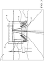
- Fig. 1 illustrates a non-limiting example of a lane-control system 10, hereafter referred to as the system 10, which is suitable for use on an automated vehicle, for example a host-vehicle 12.
- the term 'automated vehicle' is not meant to suggest that fully automated or autonomous operation of the host-vehicle 12 is required.
- teachings presented herein are applicable to instances where the host-vehicle 12 is entirely manually operated by a human and the automation is merely providing a lane-keep-assist (LKA) or a lane-centering (LC) to the human, and possibly operating the brakes of the host-vehicle 12 to prevent the host-vehicle 12 from entering a travel-path of an approaching vehicle.
- LKA lane-keep-assist
- LC lane-centering
- the system 10 includes a camera 14 used to capture an image 16 of a roadway 18 traveled by the host-vehicle 12.
- Examples of the camera 14 suitable for use on the host-vehicle 12 are commercially available as will be recognized by those in the art, one such being the APTINA MT9V023 from Micron Technology, Inc. of Boise, Idaho, USA.
- the camera 14 may be mounted on the front of the host-vehicle 12, or mounted in the interior of the host-vehicle 12 at a location suitable for the camera 14 to view the area around the host-vehicle 12 through the windshield of the host-vehicle 12.
- the camera 14 is preferably a video type camera 14 or camera 14 that can capture images 16 of the roadway 18 and surrounding area at a sufficient frame-rate, of ten frames per second, for example.
- the system 10 also includes a lidar-sensor 20 that may detect a discontinuity 22 in the roadway 18.
- the discontinuity 22 may be of any magnitude measurable by the lidar-sensor 20 (a few millimeters to several hundred millimeters for example) and may include, but is not limited to, a pothole, road debris, dip, peak, or a pavement transition, for example.
- the discontinuity 22 may span the entire width of the roadway 18, or may span only a portion of the roadway 18.
- the lidar-sensor 20 may detect the discontinuity 22 at a range in excess of two-hundred meters (200m), based on the reflectivity of the discontinuity 22 and an unencumbered line-of-sight between the discontinuity 22 and the lidar-sensor 20.
- the system 10 also includes a controller 24 in communication with the camera 14 and the lidar-sensor 20.
- the controller 24 may include a processor (not specifically shown) such as a microprocessor or other control circuitry such as analog and/or digital control circuitry including an application specific integrated circuit (ASIC) for processing data as should be evident to those in the art.
- the controller 24 may include a memory (not specifically shown), including nonvolatile memory, such as electrically erasable programmable read-only memory (EEPROM) for storing one or more routines, thresholds, and captured data.
- EEPROM electrically erasable programmable read-only memory
- the one or more routines may be executed by the processor to perform steps for determining if a detected instance of the discontinuity 22 in the roadway 18 is going to be in the intended path of the host-vehicle 12 based on signals received by the controller 24 from the lidar-sensor 20 and camera 14 as described herein.
- the controller 24 may define an area-of-interest 26 ( Fig. 2 ) within the image 16 to identify features of the roadway 18 including, but not limited to, lane-markings 28, road-edges 30, vanishing points, and other features characteristic of the roadway 18 that may be used for LKA and/or LC, and will be understood by one skilled in the art.
- Fig 2 illustrates the area-of-interest 26 within the image 16 as captured by the camera 14.
- a bottom-edge of the area-of-interest 26 may be at any position in front of the host-vehicle 12, and preferably is located at a position that is 1.5 seconds ahead of the host-vehicle 12, regardless of a velocity (not shown) of the host-vehicle 12.
- the controller 24 is further configured to construct a road-model 32 of the roadway 18 based on the features detected in the area-of-interest 26, as shown in Fig. 2 .
- the road-model 32 may be updated with new information from the camera 14 and the lidar-sensor 20 as the host-vehicle 12 moves along the roadway 18.
- the road-model 32 may be updated at rate equal to the frame-rate of the camera 14, or may be updated at a slower rate to satisfy any computational limitations. Kalman filters may be used to track the lane-edges, for example, and will be recognized by those skilled in the art.
- the controller 24 may also assume some or all control of the vehicle-controls 34 ( Fig. 1 ) of the host-vehicle 12 based on the road-model 32 as will be understood by one skilled in the art of autonomous controls.
- the controller 24 is further configured to determine that the host-vehicle 12 is approaching the discontinuity 22 in anticipation of the aforementioned transient-event.
- the controller 24 may track the discontinuity 22 and determine a time-of-arrival to the discontinuity 22 based on the velocity of the host-vehicle 12 and based on the distance (not specifically shown) to the discontinuity 22.
- the time-of arrival may be updated at a rate equal to a clock-speed (not shown) of the controller 24, or at a slower rate to satisfy any computational limitations, or may be varied based on the velocity of the host-vehicle 12.
- the time-of-arrival may be stored in the memory of the controller 24 and may be associated with a track of the discontinuity 22.
- the controller 24 is further configured to adjust the area-of-interest 26 within the image 16, in anticipation of the host-vehicle 12 arriving at the discontinuity 22, and based on the discontinuity 22 to create an adjusted-area-of-interest 36 ( Fig. 3 ).
- the adjusted-area-of-interest 36 may be used to compensate for any missing data and/or induced-noise in the image 16 that occurs, such as an instantaneous change in the position of the lane-markings 28 in the image 16, while the host-vehicle 12 is traveling over the discontinuity 22 thus creating a disruption in a field-of-view of the camera 14 as the host-vehicle 12 reacts to the discontinuity 22.
- FIG. 3 illustrates the adjusted-area-of-interest 36 compared to a transient-area-of-interest 38, where the transient-area-of-interest 38 illustrates a view of the camera 14 at a moment in time after the host-vehicle 12 has reached the discontinuity 22, and the host-vehicle 12 is reacting to (e.g. pitching, jouncing, rolling, etc.) the discontinuity 22 by pointing the camera 14 in an upward and leftward direction, for example.
- the transient-area-of-interest 38 illustrates a view of the camera 14 at a moment in time after the host-vehicle 12 has reached the discontinuity 22, and the host-vehicle 12 is reacting to (e.g. pitching, jouncing, rolling, etc.) the discontinuity 22 by pointing the camera 14 in an upward and leftward direction, for example.
- the adjusted-area-of-interest 36 is shifted rightward and downward relative to the transient-area-of-interest 38 to align with a previous-area-of-interest 40 to compensate for an impending-reaction of the host-vehicle 12 to the discontinuity 22.
- the previous-area-of-interest 40 is defined as the last area-of-interest 26 used to update the road-model 32 before the host-vehicle 12 reaches the discontinuity 22.
- the road-model 32 may then be updated with information from the adjusted-area-of-interest 36, eliminating any disruption in updating the road-model 32 that may have occurred if the transient-area-of-interest 38 were relied upon, thereby enabling the controller 24 to steer the host-vehicle 12 as if there were no discontinuity 22.
- the duration of the transient-event may last for several seconds depending on the magnitude of the discontinuity 22, during which the road-model 32 is updated according to the adjusted-area-of-interest 36 until a transient-response of the host-vehicle 12 falls below a user defined threshold and a stable host-vehicle 12 reaction to the roadway 18 is re-established.
- the adjusted-area-of-interest 36 to update the road-model 32 is beneficial because it requires less computational resources than some prior-art-systems that may track a reference-object in the image 16, so that the area-of-interest 26 can be adjusted in response to a movement of the reference-object.
- This tracking of the reference-object typically requires a significant amount of computational resources when the discontinuity 22 is sufficiently large such that the controller 24 is required to search the entire image 16 in order to re-locate the reference-object.
- the system 10 described herein anticipates how the area-of-interest 26 will move in a future image 16 as a result of the discontinuity 22, which reduces the image-processing burden on the controller 24 because the entire image 16 need not be searched for the reference-object.
- the controller 24 may use a transformation, such as an Affine-transformation and/or a Perspective-transformation to create the adjusted-area-of-interest 36 where the image 16 is rotated to account for an angle change in the field-of-view of the camera 14 and determine the real-world coordinates of the lane-markings 28.
- the controller 24 may determine the type of transformation required based on the discontinuity 22. That is, if the discontinuity 22 is detected to be a sudden vertical drop in the roadway 18 the controller 24 may use the Affine-transformation, for example. It the discontinuity 22 is detected to be a ramp, the controller 24 may use the Perspective-transformation, for example.
- the controller 24 may use a dynamic-model 42 ( Fig. 1 ) of the host-vehicle 12 to anticipate the reaction of the host-vehicle 12 to the discontinuity 22.
- the dynamic-model 42 estimates a dynamic-response of the host-vehicle 12 to various inputs, including, but not limited to, a suspension-input, a steering-input, a velocity-input, a wheel-speed input, and a cargo-load-input.
- the dynamic-model 42 may also include components such as aerodynamic, geometric, mass, motion, tire, and roadway 18 specific components that may describe the motion of the host-vehicle 12 under a variety of conditions, and will be understood by one skilled in the art.
- a lane-control system 10 a camera 14, a lidar-sensor 20, and a controller 24 for the lane-control system 10 is provided.
- the lane-control system 10 is an improvement over other lane control systems because it anticipates discontinuities 22 in the roadway 18 and compensates for erroneous vision-system inputs.
Landscapes
- Engineering & Computer Science (AREA)
- Physics & Mathematics (AREA)
- General Physics & Mathematics (AREA)
- Radar, Positioning & Navigation (AREA)
- Multimedia (AREA)
- Remote Sensing (AREA)
- Theoretical Computer Science (AREA)
- Electromagnetism (AREA)
- Mechanical Engineering (AREA)
- Transportation (AREA)
- Computer Networks & Wireless Communication (AREA)
- Automation & Control Theory (AREA)
- Traffic Control Systems (AREA)
- Computer Vision & Pattern Recognition (AREA)
- Aviation & Aerospace Engineering (AREA)
- Optics & Photonics (AREA)
Description
- This disclosure generally relates to a lane-control system suitable for use on an automated vehicle, and more particularly relates to a system that compensates the vision sensing.
- It is known to apply lane-keep assist and/or lane-centering methods to vehicles traveling roadways. These methods rely on the continuous feed of information from a vision system mounted on the vehicle. The loss of vision system data may cause the various lane-keep-assist and lane-centering methods perform sub-optimally, or fail to perform their intended function. A lane-control system is known from
WO 03/093857 A2 - In accordance with one embodiment, a lane-control system suitable for use on an automated vehicle is provided. The lane-control system includes a camera, a lidar-sensor, and a controller. The camera is used to capture an image of a roadway traveled by a host-vehicle. The lidar-sensor is used to detect a discontinuity in the roadway. The controller is in communication with the camera and the lidar-sensor and defines an area-of-interest within the image, constructs a road-model of the roadway based on the area-of-interest, determines that the host-vehicle is approaching the discontinuity, and adjusts the area-of-interest within the image based on the discontinuity.
- The controller may further control the host-vehicle based on the road-model. The controller may adjust the area-of-interest to align with a previous-area-of-interest. The controller may adjust the area-of-interest based on a dynamic-model of the host-vehicle.
- Further features and advantages will appear more clearly on a reading of the following detailed description of the preferred embodiment, which is given by way of non-limiting example only and with reference to the accompanying drawings.
- The present invention will now be described, by way of example with reference to the accompanying drawings, in which:
-
Fig. 1 is an illustration of a lane-control system in accordance with one embodiment; -
Fig. 2 is an illustration of an image in accordance with one embodiment; and -
Fig. 3 is an illustration of an image in accordance with one embodiment. - Roadways traveled by a host-
vehicle 12 are seldom flat and smooth, and often contain irregularities such as pot holes, debris, and discontinuities from bridge overpasses and on-ramps that may have transient influences on the suspension and/or trajectory of the host-vehicle 12. Described herein is a lane-control system 10 that anticipates such a transient-event and maintains control of the host-vehicle 12 through the transient-event when the vision-system data may otherwise become disrupted. -
Fig. 1 illustrates a non-limiting example of a lane-control system 10, hereafter referred to as thesystem 10, which is suitable for use on an automated vehicle, for example a host-vehicle 12. As used herein, the term 'automated vehicle' is not meant to suggest that fully automated or autonomous operation of the host-vehicle 12 is required. It is contemplated that the teachings presented herein are applicable to instances where the host-vehicle 12 is entirely manually operated by a human and the automation is merely providing a lane-keep-assist (LKA) or a lane-centering (LC) to the human, and possibly operating the brakes of the host-vehicle 12 to prevent the host-vehicle 12 from entering a travel-path of an approaching vehicle. - The
system 10 includes acamera 14 used to capture animage 16 of aroadway 18 traveled by the host-vehicle 12. Examples of thecamera 14 suitable for use on the host-vehicle 12 are commercially available as will be recognized by those in the art, one such being the APTINA MT9V023 from Micron Technology, Inc. of Boise, Idaho, USA. Thecamera 14 may be mounted on the front of the host-vehicle 12, or mounted in the interior of the host-vehicle 12 at a location suitable for thecamera 14 to view the area around the host-vehicle 12 through the windshield of the host-vehicle 12. Thecamera 14 is preferably avideo type camera 14 orcamera 14 that can captureimages 16 of theroadway 18 and surrounding area at a sufficient frame-rate, of ten frames per second, for example. - The
system 10 also includes a lidar-sensor 20 that may detect adiscontinuity 22 in theroadway 18. Thediscontinuity 22 may be of any magnitude measurable by the lidar-sensor 20 (a few millimeters to several hundred millimeters for example) and may include, but is not limited to, a pothole, road debris, dip, peak, or a pavement transition, for example. Thediscontinuity 22 may span the entire width of theroadway 18, or may span only a portion of theroadway 18. The lidar-sensor 20 may detect thediscontinuity 22 at a range in excess of two-hundred meters (200m), based on the reflectivity of thediscontinuity 22 and an unencumbered line-of-sight between thediscontinuity 22 and the lidar-sensor 20. - The
system 10 also includes acontroller 24 in communication with thecamera 14 and the lidar-sensor 20. Thecontroller 24 may include a processor (not specifically shown) such as a microprocessor or other control circuitry such as analog and/or digital control circuitry including an application specific integrated circuit (ASIC) for processing data as should be evident to those in the art. Thecontroller 24 may include a memory (not specifically shown), including nonvolatile memory, such as electrically erasable programmable read-only memory (EEPROM) for storing one or more routines, thresholds, and captured data. The one or more routines may be executed by the processor to perform steps for determining if a detected instance of thediscontinuity 22 in theroadway 18 is going to be in the intended path of the host-vehicle 12 based on signals received by thecontroller 24 from the lidar-sensor 20 andcamera 14 as described herein. - The
controller 24 may define an area-of-interest 26 (Fig. 2 ) within theimage 16 to identify features of theroadway 18 including, but not limited to, lane-markings 28, road-edges 30, vanishing points, and other features characteristic of theroadway 18 that may be used for LKA and/or LC, and will be understood by one skilled in the art.Fig 2 . illustrates the area-of-interest 26 within theimage 16 as captured by thecamera 14. A bottom-edge of the area-of-interest 26 may be at any position in front of the host-vehicle 12, and preferably is located at a position that is 1.5 seconds ahead of the host-vehicle 12, regardless of a velocity (not shown) of the host-vehicle 12. - The
controller 24 is further configured to construct a road-model 32 of theroadway 18 based on the features detected in the area-of-interest 26, as shown inFig. 2 . The road-model 32 may be updated with new information from thecamera 14 and the lidar-sensor 20 as the host-vehicle 12 moves along theroadway 18. The road-model 32 may be updated at rate equal to the frame-rate of thecamera 14, or may be updated at a slower rate to satisfy any computational limitations. Kalman filters may be used to track the lane-edges, for example, and will be recognized by those skilled in the art. Thecontroller 24 may also assume some or all control of the vehicle-controls 34 (Fig. 1 ) of the host-vehicle 12 based on the road-model 32 as will be understood by one skilled in the art of autonomous controls. - The
controller 24 is further configured to determine that the host-vehicle 12 is approaching thediscontinuity 22 in anticipation of the aforementioned transient-event. Once thediscontinuity 22 is detected by the lidar-sensor 20, thecontroller 24 may track thediscontinuity 22 and determine a time-of-arrival to thediscontinuity 22 based on the velocity of the host-vehicle 12 and based on the distance (not specifically shown) to thediscontinuity 22. The time-of arrival may be updated at a rate equal to a clock-speed (not shown) of thecontroller 24, or at a slower rate to satisfy any computational limitations, or may be varied based on the velocity of the host-vehicle 12. The time-of-arrival may be stored in the memory of thecontroller 24 and may be associated with a track of thediscontinuity 22. - The
controller 24 is further configured to adjust the area-of-interest 26 within theimage 16, in anticipation of the host-vehicle 12 arriving at thediscontinuity 22, and based on thediscontinuity 22 to create an adjusted-area-of-interest 36 (Fig. 3 ). The adjusted-area-of-interest 36 may be used to compensate for any missing data and/or induced-noise in theimage 16 that occurs, such as an instantaneous change in the position of the lane-markings 28 in theimage 16, while the host-vehicle 12 is traveling over thediscontinuity 22 thus creating a disruption in a field-of-view of thecamera 14 as the host-vehicle 12 reacts to thediscontinuity 22. This disruption in the field-of-view of thecamera 14 may lead to sub-optimal steering control where the steering commands from thecontroller 24 fluctuate.Fig. 3 illustrates the adjusted-area-of-interest 36 compared to a transient-area-of-interest 38, where the transient-area-of-interest 38 illustrates a view of thecamera 14 at a moment in time after the host-vehicle 12 has reached thediscontinuity 22, and the host-vehicle 12 is reacting to (e.g. pitching, jouncing, rolling, etc.) thediscontinuity 22 by pointing thecamera 14 in an upward and leftward direction, for example. In the non-limiting example illustrated inFig. 3 , as the host-vehicle 12 reaches thediscontinuity 22 the adjusted-area-of-interest 36 is shifted rightward and downward relative to the transient-area-of-interest 38 to align with a previous-area-of-interest 40 to compensate for an impending-reaction of the host-vehicle 12 to thediscontinuity 22. The previous-area-of-interest 40 is defined as the last area-of-interest 26 used to update the road-model 32 before the host-vehicle 12 reaches thediscontinuity 22. As the host-vehicle 12 passes over thediscontinuity 22, the road-model 32 may then be updated with information from the adjusted-area-of-interest 36, eliminating any disruption in updating the road-model 32 that may have occurred if the transient-area-of-interest 38 were relied upon, thereby enabling thecontroller 24 to steer the host-vehicle 12 as if there were nodiscontinuity 22. The duration of the transient-event may last for several seconds depending on the magnitude of thediscontinuity 22, during which the road-model 32 is updated according to the adjusted-area-of-interest 36 until a transient-response of the host-vehicle 12 falls below a user defined threshold and a stable host-vehicle 12 reaction to theroadway 18 is re-established. - Using the adjusted-area-of-
interest 36 to update the road-model 32 is beneficial because it requires less computational resources than some prior-art-systems that may track a reference-object in theimage 16, so that the area-of-interest 26 can be adjusted in response to a movement of the reference-object. This tracking of the reference-object typically requires a significant amount of computational resources when thediscontinuity 22 is sufficiently large such that thecontroller 24 is required to search theentire image 16 in order to re-locate the reference-object. In contrast, thesystem 10 described herein anticipates how the area-of-interest 26 will move in afuture image 16 as a result of thediscontinuity 22, which reduces the image-processing burden on thecontroller 24 because theentire image 16 need not be searched for the reference-object. - The
controller 24 may use a transformation, such as an Affine-transformation and/or a Perspective-transformation to create the adjusted-area-of-interest 36 where theimage 16 is rotated to account for an angle change in the field-of-view of thecamera 14 and determine the real-world coordinates of the lane-markings 28. Thecontroller 24 may determine the type of transformation required based on thediscontinuity 22. That is, if thediscontinuity 22 is detected to be a sudden vertical drop in theroadway 18 thecontroller 24 may use the Affine-transformation, for example. It thediscontinuity 22 is detected to be a ramp, thecontroller 24 may use the Perspective-transformation, for example. - The
controller 24 may use a dynamic-model 42 (Fig. 1 ) of the host-vehicle 12 to anticipate the reaction of the host-vehicle 12 to thediscontinuity 22. The dynamic-model 42 estimates a dynamic-response of the host-vehicle 12 to various inputs, including, but not limited to, a suspension-input, a steering-input, a velocity-input, a wheel-speed input, and a cargo-load-input. The dynamic-model 42 may also include components such as aerodynamic, geometric, mass, motion, tire, androadway 18 specific components that may describe the motion of the host-vehicle 12 under a variety of conditions, and will be understood by one skilled in the art. - Accordingly, a lane-
control system 10, acamera 14, a lidar-sensor 20, and acontroller 24 for the lane-control system 10 is provided. The lane-control system 10 is an improvement over other lane control systems because it anticipatesdiscontinuities 22 in theroadway 18 and compensates for erroneous vision-system inputs. - While this invention has been described in terms of the preferred embodiments thereof, it is not intended to be so limited, but rather only to the extent set forth in the claims that follow. Moreover, the use of the terms first, second, upper, lower, etc. does not denote any order of importance, location, or orientation, but rather the terms first, second, etc. are used to distinguish one element from another. Furthermore, the use of the terms a, an, etc. do not denote a limitation of quantity, but rather denote the presence of at least one of the referenced items.
Claims (4)
- A lane-control system (10) suitable for use on an automated vehicle, said system (10) comprising:a camera (14) used to capture an image (16) of a roadway (18) traveled by a host-vehicle (12);a lidar-sensor (20) used to detect a discontinuity (22) in the roadway (18); anda controller (24) in communication with the camera (14) and the lidar-sensor (20), wherein the controller (24) defines an area-of-interest (26) within the image (16),
constructs a road-model (32) of the roadway (18) based on the area-of-interest (26), determines that the host-vehicle (12) is approaching the discontinuity (22), and adjusts the area-of-interest (26) within the image (16) based on the discontinuity (22). - The system (10) in accordance with claim 1, wherein the controller (24) further controls the host-vehicle (12) based on the road-model (32).
- The system (10) according to any one of the preceding claims, wherein the controller (24) adjusts the area-of-interest (26) to align with a previous-area-of-interest (40).
- The system (10) according to any one of the preceding claims, wherein the controller (24) adjusts the area-of-interest (26) based on a dynamic-model (42) of the host-vehicle (12).
Applications Claiming Priority (1)
| Application Number | Priority Date | Filing Date | Title |
|---|---|---|---|
| US15/371,635 US10078334B2 (en) | 2016-12-07 | 2016-12-07 | Vision sensing compensation |
Publications (2)
| Publication Number | Publication Date |
|---|---|
| EP3336582A1 EP3336582A1 (en) | 2018-06-20 |
| EP3336582B1 true EP3336582B1 (en) | 2019-08-14 |
Family
ID=60452488
Family Applications (1)
| Application Number | Title | Priority Date | Filing Date |
|---|---|---|---|
| EP17203382.1A Active EP3336582B1 (en) | 2016-12-07 | 2017-11-23 | Vision sensing compensation |
Country Status (3)
| Country | Link |
|---|---|
| US (1) | US10078334B2 (en) |
| EP (1) | EP3336582B1 (en) |
| CN (2) | CN113147757A (en) |
Families Citing this family (7)
| Publication number | Priority date | Publication date | Assignee | Title |
|---|---|---|---|---|
| JP2018173834A (en) * | 2017-03-31 | 2018-11-08 | 本田技研工業株式会社 | Vehicle controller |
| US10796477B2 (en) * | 2017-06-20 | 2020-10-06 | Edx Technologies, Inc. | Methods, devices, and systems for determining field of view and producing augmented reality |
| US10969785B2 (en) * | 2017-07-24 | 2021-04-06 | Motional Ad Llc | Automated vehicle operation to compensate for sensor field-of-view limitations |
| CN111238494B (en) | 2018-11-29 | 2022-07-19 | 财团法人工业技术研究院 | Carrier, carrier positioning system and carrier positioning method |
| JP7402129B2 (en) * | 2020-07-01 | 2023-12-20 | 京セラ株式会社 | Electromagnetic wave detection device, ranging device, and electromagnetic wave detection method |
| US11861865B2 (en) | 2021-12-02 | 2024-01-02 | Argo AI, LLC | Automated vehicle pose validation |
| US12043290B2 (en) | 2022-06-08 | 2024-07-23 | Ford Global Technologies, Llc | State identification for road actors with uncertain measurements based on compliant priors |
Family Cites Families (27)
| Publication number | Priority date | Publication date | Assignee | Title |
|---|---|---|---|---|
| EP1504276B1 (en) | 2002-05-03 | 2012-08-08 | Donnelly Corporation | Object detection system for vehicle |
| JP2007311904A (en) * | 2006-05-16 | 2007-11-29 | Victor Co Of Japan Ltd | Drive recorder, video image correction method thereof, drive recorder, and system thereof |
| US7872764B2 (en) * | 2007-10-16 | 2011-01-18 | Magna Electronics Inc. | Machine vision for predictive suspension |
| US8605947B2 (en) * | 2008-04-24 | 2013-12-10 | GM Global Technology Operations LLC | Method for detecting a clear path of travel for a vehicle enhanced by object detection |
| DE102008062534A1 (en) * | 2008-12-16 | 2010-06-17 | Daimler Ag | Monitoring device for vehicle, comprises camera and display device in field of vision of driver, where camera is arranged in front area of vehicle |
| DE102009033219A1 (en) * | 2009-01-23 | 2010-07-29 | Daimler Ag | Method for determining a road profile of a traffic lane ahead of a vehicle |
| KR101743647B1 (en) * | 2011-01-21 | 2017-06-05 | 현대모비스 주식회사 | Apparatus And Method correcting guideline of rear image using vehicle |
| US9533539B2 (en) | 2011-10-20 | 2017-01-03 | GM Global Technology Operations LLC | Vehicle suspension system and method of using the same |
| DE102011056671A1 (en) * | 2011-12-20 | 2013-06-20 | Conti Temic Microelectronic Gmbh | Determining a height profile of a vehicle environment using a 3D camera |
| DE102012001951A1 (en) * | 2012-02-02 | 2013-08-08 | Daimler Ag | A display device for a vehicle and method for operating a display device |
| DE102012101085A1 (en) * | 2012-02-10 | 2013-08-14 | Conti Temic Microelectronic Gmbh | Determining a condition of a road surface by means of a 3D camera |
| JP6141601B2 (en) * | 2012-05-15 | 2017-06-07 | 東芝アルパイン・オートモティブテクノロジー株式会社 | In-vehicle camera automatic calibration device |
| DE102012112724A1 (en) * | 2012-12-20 | 2014-06-26 | Continental Teves Ag & Co. Ohg | Method for determining a road condition from environmental sensor data |
| DE102013201379B4 (en) * | 2013-01-29 | 2020-12-10 | Robert Bosch Gmbh | Motorcycle with a camera system |
| CN103196418A (en) * | 2013-03-06 | 2013-07-10 | 山东理工大学 | Measuring method of vehicle distance at curves |
| CN104135599A (en) * | 2013-05-03 | 2014-11-05 | 能晶科技股份有限公司 | Lens image correction system and lens image correction method |
| KR101519199B1 (en) * | 2013-05-09 | 2015-05-11 | 현대자동차주식회사 | System and Method for Detecting of Road |
| CN103455144B (en) * | 2013-08-22 | 2017-04-12 | 深圳先进技术研究院 | Vehicle-mounted man-machine interaction system and method |
| DE102014008425B4 (en) * | 2014-06-07 | 2017-09-14 | Audi Ag | Method for proactively controlling suspension components |
| US9733348B2 (en) * | 2014-07-03 | 2017-08-15 | GM Global Technology Operations LLC | Vehicle radar with beam adjustment |
| KR101621370B1 (en) * | 2014-08-13 | 2016-05-17 | 고려대학교 산학협력단 | Method and Apparatus for detecting lane of road |
| JP6651702B2 (en) * | 2015-03-23 | 2020-02-19 | 富士通株式会社 | Object detection device, object detection method, and information processing program |
| US9880263B2 (en) | 2015-04-06 | 2018-01-30 | Waymo Llc | Long range steerable LIDAR system |
| CN105894607B (en) * | 2015-04-30 | 2018-09-07 | 睿驰智能汽车(广州)有限公司 | Bicycle recording apparatus and the adjustment control method for utilizing bicycle recording apparatus |
| US10339390B2 (en) * | 2016-02-23 | 2019-07-02 | Semiconductor Components Industries, Llc | Methods and apparatus for an imaging system |
| CN105946718B (en) * | 2016-06-08 | 2019-04-05 | 深圳芯智汇科技有限公司 | The method of car-mounted terminal and its switching display reverse image |
| CN205665752U (en) * | 2016-06-16 | 2016-10-26 | 安徽机电职业技术学院 | Automobile data recorder |
-
2016
- 2016-12-07 US US15/371,635 patent/US10078334B2/en active Active
-
2017
- 2017-11-23 EP EP17203382.1A patent/EP3336582B1/en active Active
- 2017-12-06 CN CN202110054343.6A patent/CN113147757A/en active Pending
- 2017-12-06 CN CN201711276245.7A patent/CN108162962B/en active Active
Non-Patent Citations (1)
| Title |
|---|
| None * |
Also Published As
| Publication number | Publication date |
|---|---|
| US20180157269A1 (en) | 2018-06-07 |
| US10078334B2 (en) | 2018-09-18 |
| EP3336582A1 (en) | 2018-06-20 |
| CN113147757A (en) | 2021-07-23 |
| CN108162962B (en) | 2021-02-05 |
| CN108162962A (en) | 2018-06-15 |
Similar Documents
| Publication | Publication Date | Title |
|---|---|---|
| EP3336582B1 (en) | Vision sensing compensation | |
| KR101551096B1 (en) | Lane changing apparatus and method of autonomous vehicle | |
| EP3243729B1 (en) | Lane-keeping system for automated vehicles | |
| US10696301B2 (en) | Vehicle control device | |
| CN107792068B (en) | Automatic vehicle lane change control system | |
| EP3608635A1 (en) | Positioning system | |
| US20200108834A1 (en) | Image-based velocity control for a turning vehicle | |
| US9457807B2 (en) | Unified motion planning algorithm for autonomous driving vehicle in obstacle avoidance maneuver | |
| US9428187B2 (en) | Lane change path planning algorithm for autonomous driving vehicle | |
| EP3243718A1 (en) | Escape-path-planning system for an automated vehicle | |
| US20180224851A1 (en) | Method and apparatus for controlling autonomous driving vehicle using dead reckoning | |
| CN108572644B (en) | Lane changing system for automotive vehicle | |
| EP3190022B1 (en) | Lane extension for vision steered automated vehicle | |
| CN107646114A (en) | Method for estimating track | |
| US20120206708A1 (en) | Method and control unit for robustly detecting a lane change of a vehicle | |
| US20160098605A1 (en) | Lane boundary line information acquiring device | |
| CN108883766B (en) | Method for modifying the steering of an automated vehicle to improve passenger comfort | |
| US20210223775A1 (en) | Automated vehicle operation to compensate for sensor field-of-view limitations | |
| KR101826628B1 (en) | Preceding vehicle recognizing method and apparatus | |
| JP6838718B2 (en) | Vehicle control device | |
| CN114526747B (en) | Lane extension for an automated vehicle with visual steering | |
| CN116252811A (en) | Vehicle control method and apparatus |
Legal Events
| Date | Code | Title | Description |
|---|---|---|---|
| PUAI | Public reference made under article 153(3) epc to a published international application that has entered the european phase |
Free format text: ORIGINAL CODE: 0009012 |
|
| STAA | Information on the status of an ep patent application or granted ep patent |
Free format text: STATUS: THE APPLICATION HAS BEEN PUBLISHED |
|
| AK | Designated contracting states |
Kind code of ref document: A1 Designated state(s): AL AT BE BG CH CY CZ DE DK EE ES FI FR GB GR HR HU IE IS IT LI LT LU LV MC MK MT NL NO PL PT RO RS SE SI SK SM TR |
|
| AX | Request for extension of the european patent |
Extension state: BA ME |
|
| RAP1 | Party data changed (applicant data changed or rights of an application transferred) |
Owner name: APTIV TECHNOLOGIES LIMITED |
|
| STAA | Information on the status of an ep patent application or granted ep patent |
Free format text: STATUS: REQUEST FOR EXAMINATION WAS MADE |
|
| 17P | Request for examination filed |
Effective date: 20181220 |
|
| RBV | Designated contracting states (corrected) |
Designated state(s): AL AT BE BG CH CY CZ DE DK EE ES FI FR GB GR HR HU IE IS IT LI LT LU LV MC MK MT NL NO PL PT RO RS SE SI SK SM TR |
|
| GRAP | Despatch of communication of intention to grant a patent |
Free format text: ORIGINAL CODE: EPIDOSNIGR1 |
|
| STAA | Information on the status of an ep patent application or granted ep patent |
Free format text: STATUS: GRANT OF PATENT IS INTENDED |
|
| INTG | Intention to grant announced |
Effective date: 20190307 |
|
| GRAS | Grant fee paid |
Free format text: ORIGINAL CODE: EPIDOSNIGR3 |
|
| GRAA | (expected) grant |
Free format text: ORIGINAL CODE: 0009210 |
|
| STAA | Information on the status of an ep patent application or granted ep patent |
Free format text: STATUS: THE PATENT HAS BEEN GRANTED |
|
| AK | Designated contracting states |
Kind code of ref document: B1 Designated state(s): AL AT BE BG CH CY CZ DE DK EE ES FI FR GB GR HR HU IE IS IT LI LT LU LV MC MK MT NL NO PL PT RO RS SE SI SK SM TR |
|
| REG | Reference to a national code |
Ref country code: GB Ref legal event code: FG4D |
|
| REG | Reference to a national code |
Ref country code: CH Ref legal event code: EP Ref country code: AT Ref legal event code: REF Ref document number: 1167690 Country of ref document: AT Kind code of ref document: T Effective date: 20190815 |
|
| REG | Reference to a national code |
Ref country code: IE Ref legal event code: FG4D |
|
| REG | Reference to a national code |
Ref country code: DE Ref legal event code: R096 Ref document number: 602017006127 Country of ref document: DE |
|
| REG | Reference to a national code |
Ref country code: NL Ref legal event code: MP Effective date: 20190814 |
|
| REG | Reference to a national code |
Ref country code: LT Ref legal event code: MG4D |
|
| PG25 | Lapsed in a contracting state [announced via postgrant information from national office to epo] |
Ref country code: FI Free format text: LAPSE BECAUSE OF FAILURE TO SUBMIT A TRANSLATION OF THE DESCRIPTION OR TO PAY THE FEE WITHIN THE PRESCRIBED TIME-LIMIT Effective date: 20190814 Ref country code: PT Free format text: LAPSE BECAUSE OF FAILURE TO SUBMIT A TRANSLATION OF THE DESCRIPTION OR TO PAY THE FEE WITHIN THE PRESCRIBED TIME-LIMIT Effective date: 20191216 Ref country code: NO Free format text: LAPSE BECAUSE OF FAILURE TO SUBMIT A TRANSLATION OF THE DESCRIPTION OR TO PAY THE FEE WITHIN THE PRESCRIBED TIME-LIMIT Effective date: 20191114 Ref country code: BG Free format text: LAPSE BECAUSE OF FAILURE TO SUBMIT A TRANSLATION OF THE DESCRIPTION OR TO PAY THE FEE WITHIN THE PRESCRIBED TIME-LIMIT Effective date: 20191114 Ref country code: SE Free format text: LAPSE BECAUSE OF FAILURE TO SUBMIT A TRANSLATION OF THE DESCRIPTION OR TO PAY THE FEE WITHIN THE PRESCRIBED TIME-LIMIT Effective date: 20190814 Ref country code: HR Free format text: LAPSE BECAUSE OF FAILURE TO SUBMIT A TRANSLATION OF THE DESCRIPTION OR TO PAY THE FEE WITHIN THE PRESCRIBED TIME-LIMIT Effective date: 20190814 Ref country code: NL Free format text: LAPSE BECAUSE OF FAILURE TO SUBMIT A TRANSLATION OF THE DESCRIPTION OR TO PAY THE FEE WITHIN THE PRESCRIBED TIME-LIMIT Effective date: 20190814 Ref country code: LT Free format text: LAPSE BECAUSE OF FAILURE TO SUBMIT A TRANSLATION OF THE DESCRIPTION OR TO PAY THE FEE WITHIN THE PRESCRIBED TIME-LIMIT Effective date: 20190814 |
|
| REG | Reference to a national code |
Ref country code: AT Ref legal event code: MK05 Ref document number: 1167690 Country of ref document: AT Kind code of ref document: T Effective date: 20190814 |
|
| PG25 | Lapsed in a contracting state [announced via postgrant information from national office to epo] |
Ref country code: RS Free format text: LAPSE BECAUSE OF FAILURE TO SUBMIT A TRANSLATION OF THE DESCRIPTION OR TO PAY THE FEE WITHIN THE PRESCRIBED TIME-LIMIT Effective date: 20190814 Ref country code: LV Free format text: LAPSE BECAUSE OF FAILURE TO SUBMIT A TRANSLATION OF THE DESCRIPTION OR TO PAY THE FEE WITHIN THE PRESCRIBED TIME-LIMIT Effective date: 20190814 Ref country code: AL Free format text: LAPSE BECAUSE OF FAILURE TO SUBMIT A TRANSLATION OF THE DESCRIPTION OR TO PAY THE FEE WITHIN THE PRESCRIBED TIME-LIMIT Effective date: 20190814 Ref country code: ES Free format text: LAPSE BECAUSE OF FAILURE TO SUBMIT A TRANSLATION OF THE DESCRIPTION OR TO PAY THE FEE WITHIN THE PRESCRIBED TIME-LIMIT Effective date: 20190814 Ref country code: GR Free format text: LAPSE BECAUSE OF FAILURE TO SUBMIT A TRANSLATION OF THE DESCRIPTION OR TO PAY THE FEE WITHIN THE PRESCRIBED TIME-LIMIT Effective date: 20191115 Ref country code: IS Free format text: LAPSE BECAUSE OF FAILURE TO SUBMIT A TRANSLATION OF THE DESCRIPTION OR TO PAY THE FEE WITHIN THE PRESCRIBED TIME-LIMIT Effective date: 20191214 |
|
| PG25 | Lapsed in a contracting state [announced via postgrant information from national office to epo] |
Ref country code: TR Free format text: LAPSE BECAUSE OF FAILURE TO SUBMIT A TRANSLATION OF THE DESCRIPTION OR TO PAY THE FEE WITHIN THE PRESCRIBED TIME-LIMIT Effective date: 20190814 |
|
| PG25 | Lapsed in a contracting state [announced via postgrant information from national office to epo] |
Ref country code: PL Free format text: LAPSE BECAUSE OF FAILURE TO SUBMIT A TRANSLATION OF THE DESCRIPTION OR TO PAY THE FEE WITHIN THE PRESCRIBED TIME-LIMIT Effective date: 20190814 Ref country code: RO Free format text: LAPSE BECAUSE OF FAILURE TO SUBMIT A TRANSLATION OF THE DESCRIPTION OR TO PAY THE FEE WITHIN THE PRESCRIBED TIME-LIMIT Effective date: 20190814 Ref country code: IT Free format text: LAPSE BECAUSE OF FAILURE TO SUBMIT A TRANSLATION OF THE DESCRIPTION OR TO PAY THE FEE WITHIN THE PRESCRIBED TIME-LIMIT Effective date: 20190814 Ref country code: DK Free format text: LAPSE BECAUSE OF FAILURE TO SUBMIT A TRANSLATION OF THE DESCRIPTION OR TO PAY THE FEE WITHIN THE PRESCRIBED TIME-LIMIT Effective date: 20190814 Ref country code: AT Free format text: LAPSE BECAUSE OF FAILURE TO SUBMIT A TRANSLATION OF THE DESCRIPTION OR TO PAY THE FEE WITHIN THE PRESCRIBED TIME-LIMIT Effective date: 20190814 Ref country code: EE Free format text: LAPSE BECAUSE OF FAILURE TO SUBMIT A TRANSLATION OF THE DESCRIPTION OR TO PAY THE FEE WITHIN THE PRESCRIBED TIME-LIMIT Effective date: 20190814 |
|
| PG25 | Lapsed in a contracting state [announced via postgrant information from national office to epo] |
Ref country code: SM Free format text: LAPSE BECAUSE OF FAILURE TO SUBMIT A TRANSLATION OF THE DESCRIPTION OR TO PAY THE FEE WITHIN THE PRESCRIBED TIME-LIMIT Effective date: 20190814 Ref country code: CZ Free format text: LAPSE BECAUSE OF FAILURE TO SUBMIT A TRANSLATION OF THE DESCRIPTION OR TO PAY THE FEE WITHIN THE PRESCRIBED TIME-LIMIT Effective date: 20190814 Ref country code: IS Free format text: LAPSE BECAUSE OF FAILURE TO SUBMIT A TRANSLATION OF THE DESCRIPTION OR TO PAY THE FEE WITHIN THE PRESCRIBED TIME-LIMIT Effective date: 20200224 Ref country code: SK Free format text: LAPSE BECAUSE OF FAILURE TO SUBMIT A TRANSLATION OF THE DESCRIPTION OR TO PAY THE FEE WITHIN THE PRESCRIBED TIME-LIMIT Effective date: 20190814 |
|
| REG | Reference to a national code |
Ref country code: DE Ref legal event code: R097 Ref document number: 602017006127 Country of ref document: DE |
|
| PLBE | No opposition filed within time limit |
Free format text: ORIGINAL CODE: 0009261 |
|
| STAA | Information on the status of an ep patent application or granted ep patent |
Free format text: STATUS: NO OPPOSITION FILED WITHIN TIME LIMIT |
|
| PG2D | Information on lapse in contracting state deleted |
Ref country code: IS |
|
| PG25 | Lapsed in a contracting state [announced via postgrant information from national office to epo] |
Ref country code: LU Free format text: LAPSE BECAUSE OF NON-PAYMENT OF DUE FEES Effective date: 20191123 Ref country code: MC Free format text: LAPSE BECAUSE OF FAILURE TO SUBMIT A TRANSLATION OF THE DESCRIPTION OR TO PAY THE FEE WITHIN THE PRESCRIBED TIME-LIMIT Effective date: 20190814 |
|
| 26N | No opposition filed |
Effective date: 20200603 |
|
| REG | Reference to a national code |
Ref country code: BE Ref legal event code: MM Effective date: 20191130 |
|
| PG25 | Lapsed in a contracting state [announced via postgrant information from national office to epo] |
Ref country code: SI Free format text: LAPSE BECAUSE OF FAILURE TO SUBMIT A TRANSLATION OF THE DESCRIPTION OR TO PAY THE FEE WITHIN THE PRESCRIBED TIME-LIMIT Effective date: 20190814 |
|
| PG25 | Lapsed in a contracting state [announced via postgrant information from national office to epo] |
Ref country code: IE Free format text: LAPSE BECAUSE OF NON-PAYMENT OF DUE FEES Effective date: 20191123 |
|
| PG25 | Lapsed in a contracting state [announced via postgrant information from national office to epo] |
Ref country code: BE Free format text: LAPSE BECAUSE OF NON-PAYMENT OF DUE FEES Effective date: 20191130 |
|
| PG25 | Lapsed in a contracting state [announced via postgrant information from national office to epo] |
Ref country code: CY Free format text: LAPSE BECAUSE OF FAILURE TO SUBMIT A TRANSLATION OF THE DESCRIPTION OR TO PAY THE FEE WITHIN THE PRESCRIBED TIME-LIMIT Effective date: 20190814 |
|
| REG | Reference to a national code |
Ref country code: CH Ref legal event code: PL |
|
| PG25 | Lapsed in a contracting state [announced via postgrant information from national office to epo] |
Ref country code: MT Free format text: LAPSE BECAUSE OF FAILURE TO SUBMIT A TRANSLATION OF THE DESCRIPTION OR TO PAY THE FEE WITHIN THE PRESCRIBED TIME-LIMIT Effective date: 20190814 Ref country code: HU Free format text: LAPSE BECAUSE OF FAILURE TO SUBMIT A TRANSLATION OF THE DESCRIPTION OR TO PAY THE FEE WITHIN THE PRESCRIBED TIME-LIMIT; INVALID AB INITIO Effective date: 20171123 |
|
| PG25 | Lapsed in a contracting state [announced via postgrant information from national office to epo] |
Ref country code: LI Free format text: LAPSE BECAUSE OF NON-PAYMENT OF DUE FEES Effective date: 20201130 Ref country code: CH Free format text: LAPSE BECAUSE OF NON-PAYMENT OF DUE FEES Effective date: 20201130 |
|
| PG25 | Lapsed in a contracting state [announced via postgrant information from national office to epo] |
Ref country code: MK Free format text: LAPSE BECAUSE OF FAILURE TO SUBMIT A TRANSLATION OF THE DESCRIPTION OR TO PAY THE FEE WITHIN THE PRESCRIBED TIME-LIMIT Effective date: 20190814 |
|
| P01 | Opt-out of the competence of the unified patent court (upc) registered |
Effective date: 20230420 |
|
| PGFP | Annual fee paid to national office [announced via postgrant information from national office to epo] |
Ref country code: GB Payment date: 20231117 Year of fee payment: 7 |
|
| PGFP | Annual fee paid to national office [announced via postgrant information from national office to epo] |
Ref country code: FR Payment date: 20231128 Year of fee payment: 7 Ref country code: DE Payment date: 20231124 Year of fee payment: 7 |