EP3336490B1 - Unbemanntes fluggerät und verfahren zum positionieren eines unbemannten fluggeräts - Google Patents
Unbemanntes fluggerät und verfahren zum positionieren eines unbemannten fluggeräts Download PDFInfo
- Publication number
- EP3336490B1 EP3336490B1 EP16204041.4A EP16204041A EP3336490B1 EP 3336490 B1 EP3336490 B1 EP 3336490B1 EP 16204041 A EP16204041 A EP 16204041A EP 3336490 B1 EP3336490 B1 EP 3336490B1
- Authority
- EP
- European Patent Office
- Prior art keywords
- aerial vehicle
- unmanned aerial
- piece
- directional information
- information
- Prior art date
- Legal status (The legal status is an assumption and is not a legal conclusion. Google has not performed a legal analysis and makes no representation as to the accuracy of the status listed.)
- Active
Links
Images

Classifications
-
- G—PHYSICS
- G05—CONTROLLING; REGULATING
- G05D—SYSTEMS FOR CONTROLLING OR REGULATING NON-ELECTRIC VARIABLES
- G05D1/00—Control of position, course, altitude or attitude of land, water, air or space vehicles, e.g. using automatic pilots
- G05D1/10—Simultaneous control of position or course in three dimensions
- G05D1/101—Simultaneous control of position or course in three dimensions specially adapted for aircraft
-
- B—PERFORMING OPERATIONS; TRANSPORTING
- B64—AIRCRAFT; AVIATION; COSMONAUTICS
- B64U—UNMANNED AERIAL VEHICLES [UAV]; EQUIPMENT THEREFOR
- B64U10/00—Type of UAV
- B64U10/10—Rotorcrafts
- B64U10/13—Flying platforms
- B64U10/14—Flying platforms with four distinct rotor axes, e.g. quadcopters
-
- G—PHYSICS
- G01—MEASURING; TESTING
- G01C—MEASURING DISTANCES, LEVELS OR BEARINGS; SURVEYING; NAVIGATION; GYROSCOPIC INSTRUMENTS; PHOTOGRAMMETRY OR VIDEOGRAMMETRY
- G01C21/00—Navigation; Navigational instruments not provided for in groups G01C1/00 - G01C19/00
- G01C21/04—Navigation; Navigational instruments not provided for in groups G01C1/00 - G01C19/00 by terrestrial means
- G01C21/08—Navigation; Navigational instruments not provided for in groups G01C1/00 - G01C19/00 by terrestrial means involving use of the magnetic field of the earth
-
- G—PHYSICS
- G01—MEASURING; TESTING
- G01S—RADIO DIRECTION-FINDING; RADIO NAVIGATION; DETERMINING DISTANCE OR VELOCITY BY USE OF RADIO WAVES; LOCATING OR PRESENCE-DETECTING BY USE OF THE REFLECTION OR RERADIATION OF RADIO WAVES; ANALOGOUS ARRANGEMENTS USING OTHER WAVES
- G01S19/00—Satellite radio beacon positioning systems; Determining position, velocity or attitude using signals transmitted by such systems
- G01S19/38—Determining a navigation solution using signals transmitted by a satellite radio beacon positioning system
- G01S19/39—Determining a navigation solution using signals transmitted by a satellite radio beacon positioning system the satellite radio beacon positioning system transmitting time-stamped messages, e.g. GPS [Global Positioning System], GLONASS [Global Orbiting Navigation Satellite System] or GALILEO
- G01S19/42—Determining position
-
- B—PERFORMING OPERATIONS; TRANSPORTING
- B64—AIRCRAFT; AVIATION; COSMONAUTICS
- B64U—UNMANNED AERIAL VEHICLES [UAV]; EQUIPMENT THEREFOR
- B64U2201/00—UAVs characterised by their flight controls
-
- B—PERFORMING OPERATIONS; TRANSPORTING
- B64—AIRCRAFT; AVIATION; COSMONAUTICS
- B64U—UNMANNED AERIAL VEHICLES [UAV]; EQUIPMENT THEREFOR
- B64U2201/00—UAVs characterised by their flight controls
- B64U2201/10—UAVs characterised by their flight controls autonomous, i.e. by navigating independently from ground or air stations, e.g. by using inertial navigation systems [INS]
- B64U2201/104—UAVs characterised by their flight controls autonomous, i.e. by navigating independently from ground or air stations, e.g. by using inertial navigation systems [INS] using satellite radio beacon positioning systems, e.g. GPS
-
- B—PERFORMING OPERATIONS; TRANSPORTING
- B64—AIRCRAFT; AVIATION; COSMONAUTICS
- B64U—UNMANNED AERIAL VEHICLES [UAV]; EQUIPMENT THEREFOR
- B64U50/00—Propulsion; Power supply
- B64U50/10—Propulsion
- B64U50/19—Propulsion using electrically powered motors
-
- G—PHYSICS
- G01—MEASURING; TESTING
- G01S—RADIO DIRECTION-FINDING; RADIO NAVIGATION; DETERMINING DISTANCE OR VELOCITY BY USE OF RADIO WAVES; LOCATING OR PRESENCE-DETECTING BY USE OF THE REFLECTION OR RERADIATION OF RADIO WAVES; ANALOGOUS ARRANGEMENTS USING OTHER WAVES
- G01S19/00—Satellite radio beacon positioning systems; Determining position, velocity or attitude using signals transmitted by such systems
- G01S19/01—Satellite radio beacon positioning systems transmitting time-stamped messages, e.g. GPS [Global Positioning System], GLONASS [Global Orbiting Navigation Satellite System] or GALILEO
- G01S19/13—Receivers
Definitions
- the invention relates to a method for positioning an unmanned aerial vehicle whose actual position deviates from a target position.
- the invention also relates to an unmanned aerial vehicle suitable for carrying out the method.
- unmanned aerial vehicles there are many possible uses of unmanned aerial vehicles in which it is desirable for the unmanned aerial vehicle to remain in a fixed, predetermined position. This includes, for example, camera recordings if a specific process is to be recorded from a defined perspective.
- Absolute information about the direction from the actual position to the target position can be obtained from position information by subtraction, but no direction information, which takes into account the current orientation of the unmanned aerial vehicle.
- document U.S. 2015/0205301 A1 introduces a flying object that automatically maintains a relative position to a target.
- the flying object can move with the target to maintain substantially the same relative position to the target.
- document US 2004/0044477 A1 presents a method for correcting a position error in a navigation system in order to better locate the position measurement of a moving object on a digital map.
- the invention is based on the object of presenting an unmanned aircraft and a method for positioning an unmanned aircraft, with which the unmanned aircraft can be moved in a targeted manner from an actual position to a target position. Based on the prior art mentioned, the object is achieved with the features of the independent claims. Advantageous embodiments are specified in the dependent claims.
- the unmanned aircraft is set in a corrective movement in the direction of the desired position on the basis of a first piece of directional information.
- a second piece of directional information is obtained.
- the first directional information is corrected using the second directional information.
- the correction movement is triggered by a control command issued by a positioning module of the aircraft is routed to a control unit of the aircraft.
- the method according to the invention is based on the idea of obtaining the directional information for the approach of the unmanned aerial vehicle to the target position in a two-stage process. From the actual position of the unmanned aircraft, the corrective movement is initiated using first direction information, so that the unmanned aircraft is set in motion approximately in the direction of the target position. However, the first piece of directional information may not be sufficiently precise to hit the target position exactly. After the start of the corrective movement, a second piece of directional information is obtained, which has a higher level of accuracy. By correcting the first direction information using the second direction information, it can be ensured that that the unmanned aerial vehicle is precisely guided to the target position with the corrective movement.
- the actual position of the unmanned aerial vehicle is determined using a GPS signal.
- GPS describes a system in which a signal is exchanged between the unmanned aerial vehicle and one or more satellites, with unidirectional data transmission from the satellite to a GPS receiver being sufficient in many cases to determine the position.
- the signal propagation time between the UAV and each satellite can be viewed to obtain the position information for the UAV.
- GPS is used generically in this patent application and is not intended to be limited to any particular commercial provider or set of satellites.
- Absolute directional information between the actual position and the target position can also be derived from the formation of the difference. It is thus known in which direction the unmanned aerial vehicle would have to move in order to approach the target position. However, this cannot be directly translated into a control command for the unmanned aerial vehicle because the current orientation of the unmanned aerial vehicle relative to the absolute direction is not necessarily known.
- the first piece of direction information can be magnetically obtained piece of direction information.
- direction information derived from the earth's magnetic field is referred to as magnetically obtained direction information.
- the magnetic direction information can, for example be determined using a compass provided on board the unmanned aerial vehicle.
- the magnetic direction information can be used to determine a direction for the start of the corrective movement based on the actual position.
- the magnetic direction information is available independently of a movement of the unmanned aerial vehicle, in many cases the magnetic direction information is not precise enough to move the unmanned aerial vehicle exactly to the target position.
- the position of the unmanned aerial vehicle changes.
- the method according to the invention can be carried out in such a way that the second directional information is derived from the change in position.
- the change in position can be determined using the GPS signal.
- the magnetically obtained direction information is used to guide the unmanned aerial vehicle roughly in the correct direction of movement right from the start of the corrective movement and to adjust this direction of movement as the corrective movement progresses using the newly acquired information.
- a threshold value can be defined for the distance covered with the corrective movement, so that the direction correction is not carried out before the distance has exceeded the threshold value.
- the second directional information can be re-determined several times in the course of the correction movement will. If the newly determined second directional information differs from the previous second directional information, the previous directional information can be corrected or replaced by the newly determined directional position. This makes it possible to compensate for disruptive influences caused, for example, by wind or by sensor noise during the course of the correction movement.
- the direction correction can be carried out in such a way that the first direction information is replaced by the second direction information at a specific point in time. With this procedure, it is possible that the direction correction leads to an abrupt change in the direction of movement of the unmanned aerial vehicle.
- a smooth transition from the first directional information to the second directional information can therefore be provided. This can be achieved, for example, by a weighting factor for the second piece of directional information, which increases continuously over time from a predetermined point in time.
- the second directional information can have completely replaced the first directional information.
- the accuracy of direction information derived from a change in position increases with the length of the route covered. If the deviation between the actual position and the target position is small, the distance covered with a corrective movement is often not sufficient to derive sufficiently precise directional information from the change in position.
- the method can therefore be carried out in such a way that a correction of a first piece of direction information is only carried out using a second piece of direction information if the distance between the actual position and the target position is greater than a predefined threshold value.
- the threshold value can be, for example, 2 m, preferably 1 m, more preferably 0.5 m, more preferably 0.2 m.
- a corrective movement can be initiated using direction information that was obtained independently of a change in position of the unmanned aerial vehicle.
- the direction information can be obtained in the same way or in a different way than the first direction information of the method according to the invention. With the corrective movement, the unmanned aerial vehicle can be approached to the actual position without the direction information being corrected.
- the invention also relates to an unmanned aerial vehicle that is suitable for carrying out the method.
- the aircraft includes a direction sensor, a computing element for deriving second direction information from a change in position of the aircraft, and a positioning module.
- the positioning module provides a control unit of the unmanned aerial vehicle with a direction specification for a corrective movement from an actual position to a target position, the corrective movement being triggered using the first direction information obtained with the direction sensor and the direction specification corrected after the start of the corrective movement using the second direction information becomes.
- the direction sensor can be a magnetic compass.
- the aircraft can be developed with additional features that are described in connection with the method according to the invention.
- the method can be developed with additional features that are described in connection with the unmanned aerial vehicle.
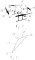
- the unmanned aerial vehicle shown comprises a fuselage body 15 with skids 16 on which the aircraft stands when it is on the ground.
- Four support struts 17 extend outwards from the fuselage body 15 .
- a drive motor 18 for driving a rotor 19 is arranged at the outer end of each supporting strut 17 .
- the rotors 19 are rotated in opposite directions, so that the aircraft takes off vertically.
- the drive motors 18 By suitably controlling the drive motors 18, the aircraft can be controlled in a targeted manner along desired trajectories.
- the unmanned aerial vehicle includes according to 3 a GPS module 20 which receives GPS signals from a plurality of satellites via an antenna 21 .
- Information about the current position of the unmanned aerial vehicle is sent to a positioning module 22, which determines the current distance between the actual Position and the target position is. If the positioning module detects a deviation, a corrective movement is triggered with the positioning module 22 with the aim of bringing the unmanned aerial vehicle back into its target position.
- a control command is sent from the positioning module 22 to a control unit 23 .
- the drive motors of the unmanned aerial vehicle are controlled in the desired manner by the control unit 23 .
- information is transmitted from the positioning module 22 to the control unit 23 as to the direction in which the corrective movement should lead.
- the absolute direction for the correction movement is known from the difference between the actual position and the target position.
- the absolute direction information cannot easily be converted into a control command for the control unit 23 because the instantaneous orientation of the unmanned aerial vehicle relative to the direction of movement cannot be derived from a single position determined using the GPS signal.
- the positioning module 22 is additionally connected to a compass 24, from which the positioning module 22 receives information about the current orientation of the unmanned aerial vehicle relative to the earth's magnetic field.
- the direction information from the compass 24 forms first direction information within the meaning of the invention, from which the positioning module 22 derives a control command in which direction the corrective movement is started.
- the distance between the actual position 25 and the target position 26 is less than a predetermined threshold value of 0.5 m, for example, only the first direction information obtained with the compass 24 is used to move the unmanned aerial vehicle to the target position 26 to lead.
- the method according to the invention in which the first directional information is corrected using second directional information, is only started when the distance between the actual position 25 and the target position 26 is greater than the threshold value.
- the correction of the direction information can be continued iteratively in the further course, even if the distance between the actual position 25 and the target position 26 becomes smaller than the threshold value during the correction movement.
- the first direction information 27 received from the compass 24 does not always correspond exactly to the direction between the actual position 25 and the target position 26 of the unmanned aerial vehicle.
- a corrective movement that simply follows the first piece of directional information 27 would therefore guide the unmanned aerial vehicle past the target position 26 .
- the positioning module 22 would determine that the distance between the actual position and the target position 26 was increasing again and would send an opposite control command to the control unit 23 . There is a risk that the unmanned aircraft could get out of control due to increasingly extreme control commands.
- the positioning module 22 determines that the position of the UAV changes. From the change in position, the positioning module 22 derives second direction information 28 about the direction between the current actual position and the target position.
- the second direction information 28 derived from the change in position generally has a higher precision than the first direction information 27 obtained with the compass 24.
- a correction of the first direction information 27 can be carried out at a point in time 29, which is after the start of the corrective movement, so that the unmanned aerial vehicle moves exactly in the direction of the desired position in a second part of the corrective movement according to the second direction information 28.
- the second piece of directional information can be determined again and again in the course of the corrective movement, so that the second piece of directional information can be adjusted if necessary.
- the method according to the invention there is therefore a two-stage sequence for the corrective movement in the direction of the setpoint position 26 presented.
- the directional specification for the corrective movement is derived from possibly less precise but always available first directional information 27 which is obtained from the compass 24 .
- the first direction information 27 is corrected using the second direction information 28 derived from the change in position, which has a higher level of accuracy.
Landscapes
- Engineering & Computer Science (AREA)
- Remote Sensing (AREA)
- Radar, Positioning & Navigation (AREA)
- Physics & Mathematics (AREA)
- General Physics & Mathematics (AREA)
- Aviation & Aerospace Engineering (AREA)
- Automation & Control Theory (AREA)
- Computer Networks & Wireless Communication (AREA)
- Life Sciences & Earth Sciences (AREA)
- Environmental & Geological Engineering (AREA)
- General Life Sciences & Earth Sciences (AREA)
- Geology (AREA)
- Mechanical Engineering (AREA)
- Navigation (AREA)
- Position Fixing By Use Of Radio Waves (AREA)
Description
- Die Erfindung betrifft ein Verfahren zum Positionieren eines unbemannten Fluggeräts, dessen Ist-Position von einer Soll-Position abweicht. Die Erfindung betrifft außerdem ein zum Durchführen des Verfahrens geeignetes unbemanntes Fluggerät.
- Bei unbemannten Fluggeräten gibt es viele Einsatzmöglichkeiten, bei denen es gewünscht ist, dass das unbemannte Fluggerät in einer festen vorgegebenen Position verbleibt. Dazu gehören beispielsweise Kameraaufnahmen, wenn ein bestimmter Ablauf aus einem definierten Blickwinkel heraus aufgezeichnet werden soll.
- Bei Einsätzen dieser Art stellt sich das Problem, dass es nicht ganz einfach ist, ein unbemanntes Fluggerät kontinuierlich in einer festen Position zu halten. So unterliegen unbemannte Fluggeräte beispielsweise einer laufenden Abdrift unter dem Einfluss von Wind. Dass eine Abweichung zwischen der Ist-Position und der Soll-Position vorliegt, kann leicht aus einer Information über die aktuelle Position abgeleitet werden.
- Nicht ganz einfach ist es festzustellen, in welche Richtung das unbemannte Fluggerät in Bewegung versetzt werden muss, um sich wieder an die Soll-Position anzunähern. Aus einer Positionsinformation kann zwar durch Differenzbildung eine absolute Information über die Richtung von der Ist-Position zur Soll-Position gewonnen werden, jedoch keine Richtungsinformation, in der die gegenwärtige Ausrichtung des unbemannten Fluggeräts berücksichtigt ist.
- Dokument
US 2015/0205301 A1 stellt ein Flugobjekt vor, dass automatisch eine relative Position zu einem Ziel einhält. Das Flugobjekt kann sich mit dem Ziel bewegen, um im Wesentlichen die gleiche relative Position zu dem Ziel einzuhalten. DokumentUS 2004/0044477 A1 stellt ein Verfahren zur Korrektur eines Positionsfehlers in einem Navigationssystem vor, um die Positionsmessung eines beweglichen Objektes auf einer digitalen Landkarte besser zu verorten. - Der Erfindung liegt die Aufgabe zugrunde, ein unbemanntes Fluggerät sowie ein Verfahren zum Positionieren eines unbemannten Fluggeräts vorzustellen, mit denen das unbemannte Fluggerät gezielt von einer Ist-Position in eine Soll-Position bewegt werden kann. Ausgehend vom genannten Stand der Technik wird die Aufgabe gelöst mit den Merkmalen der unabhängigen Ansprüche. Vorteilhafte Ausführungsformen sind in den Unteransprüchen angegeben.
- Bei dem erfindungsgemäßen Verfahren wird zunächst festgestellt, dass die Ist-Position des Fluggeräts von einer Soll-Position abweicht. Das unbemannte Fluggerät wird anhand einer ersten Richtungsinformation in Richtung der Soll-Position in eine Korrekturbewegung versetzt. Nach Beginn der Korrekturbewegung wird eine zweite Richtungsinformation gewonnen. Die erste Richtungsinformation wird anhand der zweiten Richtungsinformation korrigiert. Die Korrekturbewegung wird durch einen Steuerbefahl ausgelöst wird, der von einem Positioniermodul des Fluggeräts zu einer Steuereinheit des Fluggeräts geleitet wird.
- Das erfindungsgemäße Verfahren beruht auf dem Gedanken, die Richtungsinformation für die Annäherung des unbemannten Fluggeräts an die Soll-Position in einem zweistufigen Ablauf zu gewinnen. Aus der Ist-Position des unbemannten Fluggeräts heraus, wird die Korrekturbewegung anhand einer ersten Richtungsinformation eingeleitet, so dass das unbemannte Fluggerät ungefähr in Richtung der Soll-Position in Bewegung versetzt wird. Die erste Richtungsinformation ist aber möglicherweise nicht hinreichend genau, um die Soll-Position exakt zu treffen. Nach Beginn der Korrekturbewegung wird eine zweite Richtungsinformation gewonnen, die eine höhere Genauigkeit hat. Indem die erste Richtungsinformation anhand der zweiten Richtungsinformation korrigiert wird, kann sichergestellt werden, dass das unbemannte Fluggerät mit der Korrekturbewegung präzise zur Soll-Position geleitet wird.
- In einer bevorzugten Ausführungsform der Erfindung wird die Ist-Position des unbemannten Fluggeräts anhand eines GPS-Signals ermittelt. GPS bezeichnet ein System, bei dem zwischen dem unbemannten Fluggerät und einem oder mehreren Satelliten ein Signal ausgetauscht wird, wobei in vielen Fällen eine unidirektionale Datenübertragung von dem Satelliten zu einem GPS-Empfänger für die Positionsermittlung ausreicht. Es kann die Signallaufzeit zwischen dem unbemannten Fluggerät und dem jeweiligen Satelliten betrachtet werden, um die Positionsinformation für das unbemannte Fluggerät zu gewinnen. Die Bezeichnung GPS wird in der vorliegenden Patentanmeldung als Gattungsbezeichnung verwendet und ist nicht als Einschränkung auf einen bestimmten kommerziellen Anbieter oder einen bestimmten Satz von Satelliten zu verstehen.
- Durch Differenzbildung zwischen der Ist-Position und der Soll-Position kann ermittelt werden, ob eine Abweichung vorliegt, die eine Korrekturbewegung erfordert. Aus der Differenzbildung kann auch eine absolute Richtungsinformation zwischen der Ist-Position und der Soll-Position abgeleitet werden. Damit ist bekannt, in welche Richtung das unbemannte Fluggerät sich für eine Annäherung an die Soll-Position bewegen müsste. Allerdings kann dies nicht unmittelbar in einen Steuerbefehl für das unbemannte Fluggerät umgesetzt werden, weil die momentane Ausrichtung des unbemannten Fluggeräts relativ zu der absoluten Richtung nicht zwangsläufig bekannt ist.
- Bei der ersten Richtungsinformation kann es sich um eine magnetisch gewonnene Richtungsinformation handeln. Als magnetisch gewonnene Richtungsinformation wird insbesondere eine aus dem Magnetfeld der Erde abgeleitete Richtungsinformation bezeichnet. Die magnetische Richtungsinformation kann beispielsweise mithilfe eines an Bord des unbemannten Fluggeräts vorgesehenen Kompasses ermittelt werden. Die magnetische Richtungsinformation kann herangezogen werden, um ausgehend von der Ist-Position eine Richtung für den Beginn der Korrekturbewegung zu ermitteln. Die magnetische Richtungsinformation ist zwar unabhängig von einer Bewegung des unbemannten Fluggeräts verfügbar, allerdings ist die magnetische Richtungsinformation in vielen Fällen nicht präzise genug, um das unbemannte Fluggerät exakt zu der Soll-Position hin zu bewegen.
- Mit dem Beginn der Korrekturbewegung tritt eine Positionsänderung des unbemannten Fluggeräts ein. Das erfindungsgemäße Verfahren kann so durchgeführt werden, dass die zweite Richtungsinformation aus der Positionsänderung abgeleitet wird. Die Positionsänderung kann dabei anhand des GPS-Signals ermittelt werden.
- Es wird also bei dieser Ausführungsform die magnetisch gewonnene Richtungsinformation genutzt, um das unbemannte Fluggerät schon zu Beginn der Korrekturbewegung grob in die richtige Bewegungsrichtung zu leiten und diese Bewegungsrichtung im weiteren Verlauf der Korrekturbewegung anhand der neu hinzugewonnenen Informationen anzupassen.
- Die Genauigkeit einer aus einer Positionsänderung abgeleiteten Richtungsinformation wird desto höher, je größer die Positionsänderung ist. Bei dem erfindungsgemäßen Verfahren kann ein Schwellwert für die mit der Korrekturbewegung zurückgelegte Distanz festgelegt werden, so dass die Richtungskorrektur nicht durchgeführt wird, bevor die Distanz den Schwellwert überschritten hat.
- Bei dem erfindungsgemäßen Verfahren kann die zweite Richtungsinformation im Laufe der Korrekturbewegung mehrfach neu ermittelt werden. Weicht die neu ermittelte zweite Richtungsinformation von der bisherigen zweiten Richtungsinformation ab, so kann die bisherige Richtungsinformation anhand der neu ermittelten Richtungsposition korrigiert werden bzw. durch diese ersetzt werden. Damit wird es möglich Störeinflüsse, die beispielsweise durch Wind oder durch Sensorrauschen hervorgerufen werden, im Laufe der Korrekturbewegung auszugleichen.
- Die Richtungskorrektur kann so durchgeführt werden, dass zu einem bestimmten Zeitpunkt die erste Richtungsinformation durch die zweite Richtungsinformation ersetzt wird. Bei dieser Vorgehensweise ist es möglich, dass die Richtungskorrektur zu einem abrupten Wechsel der Bewegungsrichtung des unbemannten Fluggeräts führt. Alternativ kann deswegen ein gleitender Übergang von der ersten Richtungsinformation zu der zweiten Richtungsinformation vorgesehen sein. Dies kann beispielsweise durch einen Gewichtungsfaktor für die zweite Richtungsinformation erreicht werden, die ab einem vorgegebenen Zeitpunkt mit der Zeit kontinuierlich ansteigt. Am Ende der Korrekturbewegung kann die zweite Richtungsinformation die erste Richtungsinformation vollständig ersetzt haben.
- Die Genauigkeit einer aus einer Positionsänderung abgeleiteten Richtungsinformation steigt mit der Länge der zurückgelegten Strecke. Ist die Abweichung zwischen der Ist-Position und der Soll-Position klein, so reicht die mit einer Korrekturbewegung zurückgelegte Strecke häufig nicht aus, um aus der Positionsänderung eine hinreichend genaue Richtungsinformation abzuleiten. Das Verfahren kann deswegen so durchgeführt werden, dass eine Korrektur einer ersten Richtungsinformation anhand einer zweiten Richtungsinformation nur dann durchgeführt wird, wenn die Distanz zwischen der Ist-Position und der Soll-Position größer ist als ein vorgegebener Schwellwert. Der Schwellwert kann beispielsweise bei 2 m, vorzugsweise bei 1 m, weiter vorzugsweise bei 0,5 m, weiter vorzugsweise bei 0,2 m liegen.
- Ist die Distanz kleiner als der Schwellwert, so kann eine Korrekturbewegung anhand einer Richtungsinformation eingeleitet werden, die unabhängig von einer Positionsänderung des unbemannten Fluggeräts gewonnen wurde. Die Richtungsinformation kann auf dieselbe Weise oder auf andere Weise gewonnen werden wie die erste Richtungsinformation des erfindungsgemäßen Verfahrens. Mit der Korrekturbewegung kann das unbemannte Fluggerät an die Ist-Position angenähert werden, ohne dass eine Korrektur der Richtungsinformation vorgenommen wird.
- Die Erfindung betrifft außerdem ein unbemanntes Fluggerät, das zum Durchführen des Verfahrens geeignet ist. Das Fluggerät umfasst einen Richtungssensor, ein Rechenelement zum Ableiten einer zweiten Richtungsinformation aus einer Positionsänderung des Fluggeräts und mit einem Positioniermodul. Das Positioniermodul macht einer Steuereinheit des unbemannten Fluggeräts eine Richtungsvorgabe für eine Korrekturbewegung von einer Ist-Position zu einer Soll-Position, wobei die Korrekturbewegung anhand der mit dem Richtungssensor gewonnenen ersten Richtungsinformation ausgelöst wird und wobei die Richtungsvorgabe nach Beginn der Korrekturbewegung anhand der zweiten Richtungsinformation korrigiert wird. Der Richtungssensor kann ein magnetischer Kompass sein.
- Das Fluggerät kann mit weiteren Merkmalen fortgebildet werden, die im Zusammenhang des erfindungsgemäßen Verfahrens beschrieben sind. Das Verfahren kann mit weiteren Merkmale fortgebildet werden, die im Zusammenhang des unbemannten Fluggeräts beschrieben sind.
- Die Erfindung wird nachfolgend unter Bezugnahme auf die beigefügten Zeichnungen anhand vorteilhafter Ausführungsformen beispielhaft beschrieben. Es zeigen:
-
Fig. 1 : ein unbemanntes Fluggerät gemäß der Erfindung; -
Fig. 2 : eine schematische Darstellung einer Korrekturbewegung des unbemannten Fluggeräts; und -
Fig. 3 : eine schematische Darstellung von Komponenten des unbemannten Fluggeräts. - Ein in
Fig. 1 gezeigtes unbemanntes Fluggerät umfasst einen Rumpfkörper 15 mit Kufen 16, auf denen das Fluggerät steht, wenn es am Boden ist. Von dem Rumpfkörper 15 erstrecken sich vier Tragstreben 17 nach außen. Am äußeren Ende jeder Tragstrebe 17 ist ein Antriebsmotor 18 zum Antrieb eines Rotors 19 angeordnet. Zum Start werden die Rotoren 19 in gegenläufige Drehung versetzt, so dass das Fluggerät senkrecht nach oben abhebt. Durch geeignete Ansteuerung der Antriebsmotoren 18 kann das Fluggerät gezielt entlang gewünschter Flugbahnen gesteuert werden. - Das unbemannte Fluggerät umfasst gemäß
Fig. 3 ein GPS-Modul 20, das über eine Antenne 21 GPS-Signale von einer Mehrzahl von Satelliten empfängt. Eine Information über die aktuelle Position des unbemannten Fluggeräts wird zu einem Positioniermodul 22 geleitet, das durch Differenzbildung zwischen der aktuellen Position (Ist-Position) und einer zuvor eingegebenen gewünschten Position (Soll-Position) ermittelt, wie groß der gegenwärtige Abstand zwischen der Ist-Position und der Soll-Position ist. Stellt das Positioniermodul eine Abweichung fest, so wird mit dem Positioniermodul 22 eine Korrekturbewegung ausgelöst mit dem Ziel, das unbemannte Fluggerät zurück in seine Soll-Position zu bringen. Von dem Positioniermodul 22 wird zu diesem Zweck ein Steuerbefehl an eine Steuereinheit 23 geleitet. Von der Steuereinheit 23 werden die Antriebsmotoren des unbemannten Fluggeräts in der gewünschten Weise angesteuert. - Insbesondere wird von dem Positioniermodul 22 eine Information an die Steuereinheit 23 übermittelt, in welche Richtung die Korrekturbewegung führen soll. Dabei ist die absolute Richtung für die Korrekturbewegung aus der Differenzbildung zwischen der Ist-Position und der Soll-Position bekannt. Allerdings kann die absolute Richtungsinformation nicht ohne weiteres in einen Steuerbefehl für die Steuereinheit 23 umgesetzt werden, weil die momentane Ausrichtung des unbemannten Fluggeräts relativ zu der Bewegungsrichtung aus einer einzelnen mit dem GPS-Signal ermittelten Position nicht abgeleitet werden kann.
- Das Positioniermodul 22 ist zusätzlich mit einem Kompass 24 verbunden, von dem das Positioniermodul 22 eine Information über die momentane Ausrichtung des unbemannten Fluggeräts relativ zum Magnetfeld der Erde erhält. Die Richtungsinformation von dem Kompass 24 bildet eine erste Richtungsinformation im Sinne der Erfindung, aus der das Positioniermodul 22 einen Steuerbefehl ableitet, in welche Richtung die Korrekturbewegung begonnen wird.
- Solange die Distanz zwischen der Ist-Position 25 und der Soll-Position 26 kleiner ist als ein vorgegebener Schwellwert von beispielsweise 0,5 m wird ausschließlich die mit dem Kompass 24 gewonnene erste Richtungsinformation verwendet, um das unbemannte Fluggerät zu der Soll-Position 26 zu führen. Das erfindungsgemäße Verfahren, bei dem die erste Richtungsinformation anhand einer zweiten Richtungsinformation korrigiert wird, wird nur dann begonnen, wenn die Distanz zwischen der Ist-Position 25 und der Soll-Position 26 größer ist als der Schwellwert. Die Korrektur der Richtungsinformation kann im weiteren Verlauf iterativ fortgesetzt werden, auch wenn die Distanz zwischen der Ist-Position 25 und der Soll-Position 26 während der Korrekturbewegung kleiner wird als der Schwellwert.
- Wie in
Fig. 2 dargestellt entspricht die von dem Kompass 24 erhaltene erste Richtungsinformation 27 nicht immer exakt der Richtung zwischen der Ist-Position 25 und der Soll-Position 26 des unbemannten Fluggeräts. Eine Korrekturbewegung, die einfach der ersten Richtungsinformation 27 folgt, würde das unbemannte Fluggerät also an der Soll-Position 26 vorbei leiten. Das Positioniermodul 22 würde zu einem gegebenen Zeitpunkt feststellen, dass der Abstand zwischen der Ist-Position und der Soll-Position 26 sich wieder vergrößert und einen entgegengesetzten Steuerbefehl an die Steuereinheit 23 senden. Es besteht die Gefahr, dass das unbemannte Fluggerät durch immer extremer werdende Steuerbefehle außer Kontrolle geraten kann. - Nach dem Beginn der Korrekturbewegung stellt das Positioniermodul 22fest, dass die Position des unbemannten Fluggeräts sich ändert. Aus der Positionsänderung leitet das Positioniermodul 22 eine zweite Richtungsinformation 28 ab über die Richtung zwischen der aktuellen Ist-Position und der Soll-Position. Die aus der Positionsänderung abgeleitete zweite Richtungsinformation 28 hat im Allgemeinen eine höhere Präzision als die mit dem Kompass 24 gewonnene erste Richtungsinformation 27.
- Gemäß
Fig. 2 kann zu einem Zeitpunkt 29, der nach dem Beginn der Korrekturbewegung liegt, eine Korrektur der ersten Richtungsinformation 27 vorgenommen werden, so dass das unbemannte Fluggerät sich in einem zweiten Teil der Korrekturbewegung gemäß der zweiten Richtungsinformation 28 exakt in Richtung der Soll-Position bewegt. Die zweite Richtungsinformation kann im Verlauf der Korrekturbewegung immer wieder neu ermittelt werden, so dass gegebenenfalls eine Anpassung der zweiten Richtungsinformation vorgenommen werden kann. - Mit dem erfindungsgemäßen Verfahren wird also ein zweistufiger Ablauf für die Korrekturbewegung in Richtung der Soll-Position 26 vorgestellt. Auf einer ersten Stufe wird die Richtungsvorgabe für die Korrekturbewegung aus einer möglicherweise weniger genauen, aber dafür immer verfügbaren ersten Richtungsinformation 27 abgeleitet, die von dem Kompass 24 gewonnen wird. Auf der zweiten Stufe wird die erste Richtungsinformation 27 korrigiert anhand der aus der Positionsänderung abgeleiteten zweiten Richtungsinformation 28, die eine höhere Genauigkeit aufweist.
Claims (13)
- Unbemanntes Fluggerät mit einem Richtungssensor (24), einem Rechenelement zum Ableiten einer zweiten Richtungsinformation aus einer Positionsänderung des unbemannten Fluggeräts und mit einem Positioniermodul (22), das einer Steuereinheit (23) des unbemannten Fluggeräts eine Richtungsvorgabe für eine Korrekturbewegung von einer Ist-Position (25) zu einer Soll-Position (26) macht, wobei die Korrekturbewegung anhand der mit dem Richtungssensor (24) gewonnenen ersten Richtungsinformation (27) ausgelöst wird, dadurch gekennzeichnet, dass die Richtungsvorgabe nach Beginn der Korrekturbewegung anhand der zweiten Richtungsinformation (28) korrigiert wird, wobei die erste Richtungsinformation (27) unabhängig von einer Positionsänderung des unbemannten Fluggeräts gewonnen wird.
- Unbemanntes Fluggerät nach Anspruch 1, dadurch gekennzeichnet, dass der Richtungssensor (24) ein magnetischer Kompass ist.
- Unbemanntes Fluggerät nach einem der Ansprüche 1 oder 2, dadurch gekennzeichnet, dass die Ist-Position (25) des Fluggeräts anhand eines GPS-Signals ermittelt wird.
- Unbemanntes Fluggerät nach einem der Ansprüche 1-3, dadurch gekennzeichnet, dass durch Differenzbildung zwischen der Ist-Position (25) und der Soll-Position (26) ermittelt wird, ob eine Korrekturbewegung erforderlich ist.
- Unbemanntes Fluggerät nach einem der Ansprüche 1 bis 4, dadurch gekennzeichnet, dass die erste Richtungsinformation (27) eine magnetisch gewonnene Richtungsinformation (28) ist.
- Unbemanntes Fluggerät nach einem der Ansprüche 1 bis 5, dadurch gekennzeichnet, dass die zweite Richtungsinformation (28) aus einer Positionsänderung abgeleitet wird.
- Unbemanntes Fluggerät nach einem der Ansprüche 1 bis 6, dadurch gekennzeichnet, dass die zweite Richtungsinformation (28) aus einem GPS-Signal abgeleitet wird.
- Unbemanntes Fluggerät nach einem der Ansprüche 1 bis 7, dadurch gekennzeichnet, dass am Ende der Korrekturbewegung die erste Richtungsinformation (27) vollständig durch die zweite Richtungsinformation (28) abgelöst ist.
- Unbemanntes Fluggerät nach Anspruch 8, dadurch gekennzeichnet, dass die Korrekturbewegung mit einem gleitenden Übergang zwischen der ersten Richtungsinformation (27) und der zweiten Richtungsinformation (28) vollzogen wird.
- Unbemanntes Fluggerät nach einem der Ansprüche 1 bis 9, dadurch gekennzeichnet, dass eine Korrektur einer ersten Richtungsinformation (27) anhand einer zweiten Richtungsinformation (28) nur dann vorgenommen wird, wenn zu Beginn der Korrekturbewegung die Distanz zwischen der Ist-Position (25) und der Soll-Position (26) größer ist als ein vorgegebener Schwellwert.
- Unbemanntes Fluggerät nach Anspruch 10, dadurch gekennzeichnet, dass der Schwellwert bei 2 m liegt.
- Unbemanntes Fluggerät nach Anspruch 10 oder 11, dadurch gekennzeichnet, dass bei einer Abweichung zwischen der Ist-Position (25) und der Soll-Position (26), die kleiner ist als der Schwellwert eine Korrekturbewegung anhand einer Richtungsinformation durchgeführt wird, die unabhängig von einer Positionsänderung des unbemannten Fluggeräts ist.
- Verfahren zum Positionieren eines unbemannten Fluggeräts, bei dem die Ist-Position (25) des Fluggeräts von einer Soll-Position (26) abweicht und bei dem das Fluggerät anhand einer ersten Richtungsinformation (27) in Richtung der Soll-Position (26) in eine Korrekturbewegung versetzt wird, wobei die Korrekturbewegung durch einen Steuerbefehl ausgelöst wird, der von einem Positioniermodul (22) des Fluggeräts zu einer Steuereinheit (23) des Fluggeräts geleitet wird, dadurch gekennzeichnet, dass nach Beginn der Korrekturbewegung eine zweite Richtungsinformation (28) aus einer Positionsänderung des unbemannten Fluggeräts gewonnen wird und wobei die erste Richtungsinformation (27) anhand der zweiten Richtungsinformation (28) korrigiert wird, wobei die erste Richtungsinformation (27) unabhängig von einer Positionsänderung des unbemannten Fluggeräts gewonnen wird.
Priority Applications (2)
| Application Number | Priority Date | Filing Date | Title |
|---|---|---|---|
| EP16204041.4A EP3336490B1 (de) | 2016-12-14 | 2016-12-14 | Unbemanntes fluggerät und verfahren zum positionieren eines unbemannten fluggeräts |
| US15/841,233 US10338607B2 (en) | 2016-12-14 | 2017-12-13 | Unmanned aerial vehicle and method for positioning an unmanned aerial vehicle |
Applications Claiming Priority (1)
| Application Number | Priority Date | Filing Date | Title |
|---|---|---|---|
| EP16204041.4A EP3336490B1 (de) | 2016-12-14 | 2016-12-14 | Unbemanntes fluggerät und verfahren zum positionieren eines unbemannten fluggeräts |
Publications (2)
| Publication Number | Publication Date |
|---|---|
| EP3336490A1 EP3336490A1 (de) | 2018-06-20 |
| EP3336490B1 true EP3336490B1 (de) | 2022-08-10 |
Family
ID=57714363
Family Applications (1)
| Application Number | Title | Priority Date | Filing Date |
|---|---|---|---|
| EP16204041.4A Active EP3336490B1 (de) | 2016-12-14 | 2016-12-14 | Unbemanntes fluggerät und verfahren zum positionieren eines unbemannten fluggeräts |
Country Status (2)
| Country | Link |
|---|---|
| US (1) | US10338607B2 (de) |
| EP (1) | EP3336490B1 (de) |
Citations (2)
| Publication number | Priority date | Publication date | Assignee | Title |
|---|---|---|---|---|
| US20100004798A1 (en) * | 2005-01-25 | 2010-01-07 | William Kress Bodin | Navigating a UAV to a next waypoint |
| US20150205301A1 (en) * | 2013-03-15 | 2015-07-23 | Ashley A. Gilmore | Digital tethering for tracking with autonomous aerial robot |
Family Cites Families (7)
| Publication number | Priority date | Publication date | Assignee | Title |
|---|---|---|---|---|
| KR100495635B1 (ko) * | 2002-09-02 | 2005-06-16 | 엘지전자 주식회사 | 네비게이션 시스템의 위치오차 보정방법 |
| US7469183B2 (en) * | 2005-01-24 | 2008-12-23 | International Business Machines Corporation | Navigating UAVs in formation |
| US9758239B2 (en) * | 2011-04-14 | 2017-09-12 | Hexagon Technology Center Gmbh | System and method for controlling an unmanned air vehicle |
| US10274958B2 (en) * | 2015-01-22 | 2019-04-30 | Bae Systems Information And Electronic Systems Integration Inc. | Method for vision-aided navigation for unmanned vehicles |
| WO2016131127A1 (en) * | 2015-02-19 | 2016-08-25 | Aeryon Labs Inc. | Systems and processes for calibrating unmanned aerial vehicles |
| US10586464B2 (en) * | 2015-07-29 | 2020-03-10 | Warren F. LeBlanc | Unmanned aerial vehicles |
| US10191486B2 (en) * | 2016-03-28 | 2019-01-29 | Aveopt, Inc. | Unmanned surveyor |
-
2016
- 2016-12-14 EP EP16204041.4A patent/EP3336490B1/de active Active
-
2017
- 2017-12-13 US US15/841,233 patent/US10338607B2/en active Active
Patent Citations (2)
| Publication number | Priority date | Publication date | Assignee | Title |
|---|---|---|---|---|
| US20100004798A1 (en) * | 2005-01-25 | 2010-01-07 | William Kress Bodin | Navigating a UAV to a next waypoint |
| US20150205301A1 (en) * | 2013-03-15 | 2015-07-23 | Ashley A. Gilmore | Digital tethering for tracking with autonomous aerial robot |
Also Published As
| Publication number | Publication date |
|---|---|
| US20180164834A1 (en) | 2018-06-14 |
| US10338607B2 (en) | 2019-07-02 |
| EP3336490A1 (de) | 2018-06-20 |
Similar Documents
| Publication | Publication Date | Title |
|---|---|---|
| DE102005038017B3 (de) | Verfahren zur Flugführung mehrerer im Verband fliegender Flugzeuge | |
| EP2125472B1 (de) | Einparkhalbautomat | |
| DE102017126878B4 (de) | Fahrerunterstützungssystem für ein Fahrzeug | |
| DE102015108605B4 (de) | Fahrspurwechselpfad-Planungsalgorithmus für ein autonom fahrendes Fahrzeug | |
| DE102017221134A1 (de) | Verfahren und Vorrichtung zum Betreiben eines mobilen Systems | |
| DE102014215243B4 (de) | Robuste Totzeit- und Dynamikkompensation für Trajektorienfolgeregelung | |
| DE102014224075A1 (de) | Verfahren und Vorrichtung zum assistierten Führen eines Fahrzeugs | |
| DE102014224077A1 (de) | Verfahren und Vorrichtung zum assistierten Führen eines Fahrzeugs | |
| DE102018217845A1 (de) | Einrichtung und Verfahren zum Regeln eines Prozesses | |
| DE102014220865B4 (de) | Stationär genaue und kooperative Trajektorienfolgeregelung | |
| DE102021111807A1 (de) | Verfahren und vorrichtung zur automatischen anpassung der querregler als reaktion auf schnelle trajektorienänderungen | |
| DE102018127322A1 (de) | Kompensation von Anhängerkupplungsvorrichtungshöhe bei automatischem Anhängerkupplungsbetrieb | |
| DE69119139T2 (de) | Methode zur Lenkung eines Flugzeuges im Tiefflug | |
| DE102021103652A1 (de) | Anhängerkupplungsunterstützungssystem mit dynamischer fahrzeugsteuerverarbeitung | |
| EP4059813B1 (de) | Regelungseinrichtung und verfahren zur lenkwinkelregelung eines fahrzeugs | |
| EP3814200A1 (de) | Verfahren zur ermittlung einer aktualisierten trajektorie für ein fahrzeug | |
| DE2750128C2 (de) | ||
| DE10030036A1 (de) | Fahrzeug-Steuerungssystem zur Bahnsteuerung unter Berücksichtigung einer das Fahrzeug beeinflussenden Strömung sowie ein Verfahren zur Erzeugung einer Bahn-Trajektorie | |
| DE102013221369B4 (de) | Verfahren zur Umfahrung eines Hindernisses | |
| WO2021233674A1 (de) | Verfahren zum ermitteln einer ausgangspose eines fahrzeugs | |
| DE102018211905A1 (de) | Steuereinrichtung für ein unbemanntes Luftfahrzeug | |
| DE69608381T2 (de) | Verfahren und Vorrichtung zur Führung eines mobilen Objektes | |
| EP3336490A1 (de) | Unbemanntes fluggerät und verfahren zum positionieren eines unbemannten fluggeräts | |
| EP1798621B1 (de) | System zum führen und operieren eines Fahrzeugs ohne Fahrer | |
| DE102007002265A1 (de) | Verfahren zum Steuern eines Kraftfahrzeugs von einer ersten Position zu einer zweiten Position |
Legal Events
| Date | Code | Title | Description |
|---|---|---|---|
| PUAI | Public reference made under article 153(3) epc to a published international application that has entered the european phase |
Free format text: ORIGINAL CODE: 0009012 |
|
| STAA | Information on the status of an ep patent application or granted ep patent |
Free format text: STATUS: THE APPLICATION HAS BEEN PUBLISHED |
|
| AK | Designated contracting states |
Kind code of ref document: A1 Designated state(s): AL AT BE BG CH CY CZ DE DK EE ES FI FR GB GR HR HU IE IS IT LI LT LU LV MC MK MT NL NO PL PT RO RS SE SI SK SM TR |
|
| AX | Request for extension of the european patent |
Extension state: BA ME |
|
| STAA | Information on the status of an ep patent application or granted ep patent |
Free format text: STATUS: REQUEST FOR EXAMINATION WAS MADE |
|
| 17P | Request for examination filed |
Effective date: 20181210 |
|
| RBV | Designated contracting states (corrected) |
Designated state(s): AL AT BE BG CH CY CZ DE DK EE ES FI FR GB GR HR HU IE IS IT LI LT LU LV MC MK MT NL NO PL PT RO RS SE SI SK SM TR |
|
| STAA | Information on the status of an ep patent application or granted ep patent |
Free format text: STATUS: EXAMINATION IS IN PROGRESS |
|
| 17Q | First examination report despatched |
Effective date: 20190605 |
|
| RAP3 | Party data changed (applicant data changed or rights of an application transferred) |
Owner name: MDGROUP GERMANY GMBH |
|
| REG | Reference to a national code |
Ref country code: DE Ref legal event code: R079 Ref document number: 502016015149 Country of ref document: DE Free format text: PREVIOUS MAIN CLASS: G01C0021300000 Ipc: B64C0039020000 |
|
| GRAP | Despatch of communication of intention to grant a patent |
Free format text: ORIGINAL CODE: EPIDOSNIGR1 |
|
| STAA | Information on the status of an ep patent application or granted ep patent |
Free format text: STATUS: GRANT OF PATENT IS INTENDED |
|
| RIC1 | Information provided on ipc code assigned before grant |
Ipc: G01S 19/49 20100101ALI20220310BHEP Ipc: G01S 19/42 20100101ALI20220310BHEP Ipc: G05D 1/10 20060101ALI20220310BHEP Ipc: G01C 21/08 20060101ALI20220310BHEP Ipc: B64C 39/02 20060101AFI20220310BHEP |
|
| INTG | Intention to grant announced |
Effective date: 20220413 |
|
| GRAS | Grant fee paid |
Free format text: ORIGINAL CODE: EPIDOSNIGR3 |
|
| GRAA | (expected) grant |
Free format text: ORIGINAL CODE: 0009210 |
|
| STAA | Information on the status of an ep patent application or granted ep patent |
Free format text: STATUS: THE PATENT HAS BEEN GRANTED |
|
| AK | Designated contracting states |
Kind code of ref document: B1 Designated state(s): AL AT BE BG CH CY CZ DE DK EE ES FI FR GB GR HR HU IE IS IT LI LT LU LV MC MK MT NL NO PL PT RO RS SE SI SK SM TR |
|
| REG | Reference to a national code |
Ref country code: AT Ref legal event code: REF Ref document number: 1510374 Country of ref document: AT Kind code of ref document: T Effective date: 20220815 Ref country code: CH Ref legal event code: EP |
|
| REG | Reference to a national code |
Ref country code: DE Ref legal event code: R096 Ref document number: 502016015149 Country of ref document: DE |
|
| REG | Reference to a national code |
Ref country code: IE Ref legal event code: FG4D Free format text: LANGUAGE OF EP DOCUMENT: GERMAN |
|
| REG | Reference to a national code |
Ref country code: NL Ref legal event code: MP Effective date: 20220810 |
|
| REG | Reference to a national code |
Ref country code: LT Ref legal event code: MG9D |
|
| PG25 | Lapsed in a contracting state [announced via postgrant information from national office to epo] |
Ref country code: SE Free format text: LAPSE BECAUSE OF FAILURE TO SUBMIT A TRANSLATION OF THE DESCRIPTION OR TO PAY THE FEE WITHIN THE PRESCRIBED TIME-LIMIT Effective date: 20220810 Ref country code: RS Free format text: LAPSE BECAUSE OF FAILURE TO SUBMIT A TRANSLATION OF THE DESCRIPTION OR TO PAY THE FEE WITHIN THE PRESCRIBED TIME-LIMIT Effective date: 20220810 Ref country code: PT Free format text: LAPSE BECAUSE OF FAILURE TO SUBMIT A TRANSLATION OF THE DESCRIPTION OR TO PAY THE FEE WITHIN THE PRESCRIBED TIME-LIMIT Effective date: 20221212 Ref country code: NO Free format text: LAPSE BECAUSE OF FAILURE TO SUBMIT A TRANSLATION OF THE DESCRIPTION OR TO PAY THE FEE WITHIN THE PRESCRIBED TIME-LIMIT Effective date: 20221110 Ref country code: NL Free format text: LAPSE BECAUSE OF FAILURE TO SUBMIT A TRANSLATION OF THE DESCRIPTION OR TO PAY THE FEE WITHIN THE PRESCRIBED TIME-LIMIT Effective date: 20220810 Ref country code: LV Free format text: LAPSE BECAUSE OF FAILURE TO SUBMIT A TRANSLATION OF THE DESCRIPTION OR TO PAY THE FEE WITHIN THE PRESCRIBED TIME-LIMIT Effective date: 20220810 Ref country code: LT Free format text: LAPSE BECAUSE OF FAILURE TO SUBMIT A TRANSLATION OF THE DESCRIPTION OR TO PAY THE FEE WITHIN THE PRESCRIBED TIME-LIMIT Effective date: 20220810 Ref country code: FI Free format text: LAPSE BECAUSE OF FAILURE TO SUBMIT A TRANSLATION OF THE DESCRIPTION OR TO PAY THE FEE WITHIN THE PRESCRIBED TIME-LIMIT Effective date: 20220810 |
|
| PG25 | Lapsed in a contracting state [announced via postgrant information from national office to epo] |
Ref country code: PL Free format text: LAPSE BECAUSE OF FAILURE TO SUBMIT A TRANSLATION OF THE DESCRIPTION OR TO PAY THE FEE WITHIN THE PRESCRIBED TIME-LIMIT Effective date: 20220810 Ref country code: IS Free format text: LAPSE BECAUSE OF FAILURE TO SUBMIT A TRANSLATION OF THE DESCRIPTION OR TO PAY THE FEE WITHIN THE PRESCRIBED TIME-LIMIT Effective date: 20221210 Ref country code: HR Free format text: LAPSE BECAUSE OF FAILURE TO SUBMIT A TRANSLATION OF THE DESCRIPTION OR TO PAY THE FEE WITHIN THE PRESCRIBED TIME-LIMIT Effective date: 20220810 Ref country code: GR Free format text: LAPSE BECAUSE OF FAILURE TO SUBMIT A TRANSLATION OF THE DESCRIPTION OR TO PAY THE FEE WITHIN THE PRESCRIBED TIME-LIMIT Effective date: 20221111 |
|
| PG25 | Lapsed in a contracting state [announced via postgrant information from national office to epo] |
Ref country code: SM Free format text: LAPSE BECAUSE OF FAILURE TO SUBMIT A TRANSLATION OF THE DESCRIPTION OR TO PAY THE FEE WITHIN THE PRESCRIBED TIME-LIMIT Effective date: 20220810 Ref country code: RO Free format text: LAPSE BECAUSE OF FAILURE TO SUBMIT A TRANSLATION OF THE DESCRIPTION OR TO PAY THE FEE WITHIN THE PRESCRIBED TIME-LIMIT Effective date: 20220810 Ref country code: ES Free format text: LAPSE BECAUSE OF FAILURE TO SUBMIT A TRANSLATION OF THE DESCRIPTION OR TO PAY THE FEE WITHIN THE PRESCRIBED TIME-LIMIT Effective date: 20220810 Ref country code: DK Free format text: LAPSE BECAUSE OF FAILURE TO SUBMIT A TRANSLATION OF THE DESCRIPTION OR TO PAY THE FEE WITHIN THE PRESCRIBED TIME-LIMIT Effective date: 20220810 Ref country code: CZ Free format text: LAPSE BECAUSE OF FAILURE TO SUBMIT A TRANSLATION OF THE DESCRIPTION OR TO PAY THE FEE WITHIN THE PRESCRIBED TIME-LIMIT Effective date: 20220810 |
|
| REG | Reference to a national code |
Ref country code: DE Ref legal event code: R097 Ref document number: 502016015149 Country of ref document: DE |
|
| PG25 | Lapsed in a contracting state [announced via postgrant information from national office to epo] |
Ref country code: SK Free format text: LAPSE BECAUSE OF FAILURE TO SUBMIT A TRANSLATION OF THE DESCRIPTION OR TO PAY THE FEE WITHIN THE PRESCRIBED TIME-LIMIT Effective date: 20220810 Ref country code: EE Free format text: LAPSE BECAUSE OF FAILURE TO SUBMIT A TRANSLATION OF THE DESCRIPTION OR TO PAY THE FEE WITHIN THE PRESCRIBED TIME-LIMIT Effective date: 20220810 |
|
| PLBE | No opposition filed within time limit |
Free format text: ORIGINAL CODE: 0009261 |
|
| STAA | Information on the status of an ep patent application or granted ep patent |
Free format text: STATUS: NO OPPOSITION FILED WITHIN TIME LIMIT |
|
| P01 | Opt-out of the competence of the unified patent court (upc) registered |
Effective date: 20230515 |
|
| PG25 | Lapsed in a contracting state [announced via postgrant information from national office to epo] |
Ref country code: AL Free format text: LAPSE BECAUSE OF FAILURE TO SUBMIT A TRANSLATION OF THE DESCRIPTION OR TO PAY THE FEE WITHIN THE PRESCRIBED TIME-LIMIT Effective date: 20220810 |
|
| 26N | No opposition filed |
Effective date: 20230511 |
|
| REG | Reference to a national code |
Ref country code: BE Ref legal event code: MM Effective date: 20221231 |
|
| PG25 | Lapsed in a contracting state [announced via postgrant information from national office to epo] |
Ref country code: SI Free format text: LAPSE BECAUSE OF FAILURE TO SUBMIT A TRANSLATION OF THE DESCRIPTION OR TO PAY THE FEE WITHIN THE PRESCRIBED TIME-LIMIT Effective date: 20220810 Ref country code: LU Free format text: LAPSE BECAUSE OF NON-PAYMENT OF DUE FEES Effective date: 20221214 |
|
| PG25 | Lapsed in a contracting state [announced via postgrant information from national office to epo] |
Ref country code: IE Free format text: LAPSE BECAUSE OF NON-PAYMENT OF DUE FEES Effective date: 20221214 |
|
| PG25 | Lapsed in a contracting state [announced via postgrant information from national office to epo] |
Ref country code: BE Free format text: LAPSE BECAUSE OF NON-PAYMENT OF DUE FEES Effective date: 20221231 |
|
| PGFP | Annual fee paid to national office [announced via postgrant information from national office to epo] |
Ref country code: GB Payment date: 20231220 Year of fee payment: 8 |
|
| PGFP | Annual fee paid to national office [announced via postgrant information from national office to epo] |
Ref country code: FR Payment date: 20231219 Year of fee payment: 8 Ref country code: DE Payment date: 20231220 Year of fee payment: 8 |
|
| REG | Reference to a national code |
Ref country code: AT Ref legal event code: MM01 Ref document number: 1510374 Country of ref document: AT Kind code of ref document: T Effective date: 20221214 |
|
| PG25 | Lapsed in a contracting state [announced via postgrant information from national office to epo] |
Ref country code: HU Free format text: LAPSE BECAUSE OF FAILURE TO SUBMIT A TRANSLATION OF THE DESCRIPTION OR TO PAY THE FEE WITHIN THE PRESCRIBED TIME-LIMIT; INVALID AB INITIO Effective date: 20161214 |
|
| PG25 | Lapsed in a contracting state [announced via postgrant information from national office to epo] |
Ref country code: AT Free format text: LAPSE BECAUSE OF NON-PAYMENT OF DUE FEES Effective date: 20221214 |
|
| PG25 | Lapsed in a contracting state [announced via postgrant information from national office to epo] |
Ref country code: CY Free format text: LAPSE BECAUSE OF FAILURE TO SUBMIT A TRANSLATION OF THE DESCRIPTION OR TO PAY THE FEE WITHIN THE PRESCRIBED TIME-LIMIT Effective date: 20220810 Ref country code: AT Free format text: LAPSE BECAUSE OF NON-PAYMENT OF DUE FEES Effective date: 20221214 |
|
| PGFP | Annual fee paid to national office [announced via postgrant information from national office to epo] |
Ref country code: CH Payment date: 20240110 Year of fee payment: 8 |
|
| PG25 | Lapsed in a contracting state [announced via postgrant information from national office to epo] |
Ref country code: MK Free format text: LAPSE BECAUSE OF FAILURE TO SUBMIT A TRANSLATION OF THE DESCRIPTION OR TO PAY THE FEE WITHIN THE PRESCRIBED TIME-LIMIT Effective date: 20220810 Ref country code: IT Free format text: LAPSE BECAUSE OF FAILURE TO SUBMIT A TRANSLATION OF THE DESCRIPTION OR TO PAY THE FEE WITHIN THE PRESCRIBED TIME-LIMIT Effective date: 20220810 |
|
| PG25 | Lapsed in a contracting state [announced via postgrant information from national office to epo] |
Ref country code: MC Free format text: LAPSE BECAUSE OF FAILURE TO SUBMIT A TRANSLATION OF THE DESCRIPTION OR TO PAY THE FEE WITHIN THE PRESCRIBED TIME-LIMIT Effective date: 20220810 |
|
| PG25 | Lapsed in a contracting state [announced via postgrant information from national office to epo] |
Ref country code: MC Free format text: LAPSE BECAUSE OF FAILURE TO SUBMIT A TRANSLATION OF THE DESCRIPTION OR TO PAY THE FEE WITHIN THE PRESCRIBED TIME-LIMIT Effective date: 20220810 |
|
| PG25 | Lapsed in a contracting state [announced via postgrant information from national office to epo] |
Ref country code: BG Free format text: LAPSE BECAUSE OF FAILURE TO SUBMIT A TRANSLATION OF THE DESCRIPTION OR TO PAY THE FEE WITHIN THE PRESCRIBED TIME-LIMIT Effective date: 20220810 |
|
| PG25 | Lapsed in a contracting state [announced via postgrant information from national office to epo] |
Ref country code: MT Free format text: LAPSE BECAUSE OF FAILURE TO SUBMIT A TRANSLATION OF THE DESCRIPTION OR TO PAY THE FEE WITHIN THE PRESCRIBED TIME-LIMIT Effective date: 20220810 |
|
| REG | Reference to a national code |
Ref country code: DE Ref legal event code: R119 Ref document number: 502016015149 Country of ref document: DE |
|
| REG | Reference to a national code |
Ref country code: CH Ref legal event code: PL |
|
| GBPC | Gb: european patent ceased through non-payment of renewal fee |
Effective date: 20241214 |
|
| PG25 | Lapsed in a contracting state [announced via postgrant information from national office to epo] |
Ref country code: DE Free format text: LAPSE BECAUSE OF NON-PAYMENT OF DUE FEES Effective date: 20250701 |
|
| PG25 | Lapsed in a contracting state [announced via postgrant information from national office to epo] |
Ref country code: GB Free format text: LAPSE BECAUSE OF NON-PAYMENT OF DUE FEES Effective date: 20241214 |
|
| PG25 | Lapsed in a contracting state [announced via postgrant information from national office to epo] |
Ref country code: FR Free format text: LAPSE BECAUSE OF NON-PAYMENT OF DUE FEES Effective date: 20241231 |
|
| PG25 | Lapsed in a contracting state [announced via postgrant information from national office to epo] |
Ref country code: CH Free format text: LAPSE BECAUSE OF NON-PAYMENT OF DUE FEES Effective date: 20241231 |
|
| PG25 | Lapsed in a contracting state [announced via postgrant information from national office to epo] |
Ref country code: TR Free format text: LAPSE BECAUSE OF FAILURE TO SUBMIT A TRANSLATION OF THE DESCRIPTION OR TO PAY THE FEE WITHIN THE PRESCRIBED TIME-LIMIT Effective date: 20220810 |