EP3336473B1 - Method for determining the charge level of a latent heat storage device - Google Patents
Method for determining the charge level of a latent heat storage device Download PDFInfo
- Publication number
- EP3336473B1 EP3336473B1 EP17200136.4A EP17200136A EP3336473B1 EP 3336473 B1 EP3336473 B1 EP 3336473B1 EP 17200136 A EP17200136 A EP 17200136A EP 3336473 B1 EP3336473 B1 EP 3336473B1
- Authority
- EP
- European Patent Office
- Prior art keywords
- phase change
- change material
- latent heat
- temperature
- heat storage
- Prior art date
- Legal status (The legal status is an assumption and is not a legal conclusion. Google has not performed a legal analysis and makes no representation as to the accuracy of the status listed.)
- Active
Links
- 238000005338 heat storage Methods 0.000 title claims description 64
- 238000000034 method Methods 0.000 title claims description 30
- 239000012782 phase change material Substances 0.000 claims description 93
- 239000013529 heat transfer fluid Substances 0.000 claims description 25
- 230000008859 change Effects 0.000 claims description 17
- 238000004364 calculation method Methods 0.000 claims description 10
- 238000009826 distribution Methods 0.000 claims description 10
- 230000017525 heat dissipation Effects 0.000 claims description 2
- 230000002123 temporal effect Effects 0.000 claims 1
- 239000012071 phase Substances 0.000 description 20
- 230000007704 transition Effects 0.000 description 8
- 238000005259 measurement Methods 0.000 description 7
- 239000000463 material Substances 0.000 description 6
- 230000008569 process Effects 0.000 description 6
- 238000013459 approach Methods 0.000 description 5
- 230000008901 benefit Effects 0.000 description 5
- 238000009413 insulation Methods 0.000 description 4
- 239000007791 liquid phase Substances 0.000 description 4
- XLYOFNOQVPJJNP-UHFFFAOYSA-N water Substances O XLYOFNOQVPJJNP-UHFFFAOYSA-N 0.000 description 4
- 230000001419 dependent effect Effects 0.000 description 3
- 238000010586 diagram Methods 0.000 description 3
- 239000012774 insulation material Substances 0.000 description 3
- 239000013078 crystal Substances 0.000 description 2
- 230000000694 effects Effects 0.000 description 2
- 238000005516 engineering process Methods 0.000 description 2
- 239000005431 greenhouse gas Substances 0.000 description 2
- 238000004519 manufacturing process Methods 0.000 description 2
- 238000013021 overheating Methods 0.000 description 2
- 230000002441 reversible effect Effects 0.000 description 2
- 239000007787 solid Substances 0.000 description 2
- 239000007790 solid phase Substances 0.000 description 2
- 230000036962 time dependent Effects 0.000 description 2
- 238000012546 transfer Methods 0.000 description 2
- TVEXGJYMHHTVKP-UHFFFAOYSA-N 6-oxabicyclo[3.2.1]oct-3-en-7-one Chemical compound C1C2C(=O)OC1C=CC2 TVEXGJYMHHTVKP-UHFFFAOYSA-N 0.000 description 1
- 238000010276 construction Methods 0.000 description 1
- 238000001816 cooling Methods 0.000 description 1
- 238000007599 discharging Methods 0.000 description 1
- 238000005315 distribution function Methods 0.000 description 1
- 238000005265 energy consumption Methods 0.000 description 1
- 238000004146 energy storage Methods 0.000 description 1
- 238000003912 environmental pollution Methods 0.000 description 1
- 230000002349 favourable effect Effects 0.000 description 1
- 239000007788 liquid Substances 0.000 description 1
- 238000000691 measurement method Methods 0.000 description 1
- 238000002844 melting Methods 0.000 description 1
- 230000008018 melting Effects 0.000 description 1
- 229920000642 polymer Polymers 0.000 description 1
- 230000009467 reduction Effects 0.000 description 1
- 230000001105 regulatory effect Effects 0.000 description 1
- 150000003839 salts Chemical class 0.000 description 1
- 238000007711 solidification Methods 0.000 description 1
- 230000008023 solidification Effects 0.000 description 1
- 230000003068 static effect Effects 0.000 description 1
- 210000000352 storage cell Anatomy 0.000 description 1
- 238000009827 uniform distribution Methods 0.000 description 1
Images


Classifications
-
- F—MECHANICAL ENGINEERING; LIGHTING; HEATING; WEAPONS; BLASTING
- F28—HEAT EXCHANGE IN GENERAL
- F28D—HEAT-EXCHANGE APPARATUS, NOT PROVIDED FOR IN ANOTHER SUBCLASS, IN WHICH THE HEAT-EXCHANGE MEDIA DO NOT COME INTO DIRECT CONTACT
- F28D20/00—Heat storage plants or apparatus in general; Regenerative heat-exchange apparatus not covered by groups F28D17/00 or F28D19/00
- F28D20/02—Heat storage plants or apparatus in general; Regenerative heat-exchange apparatus not covered by groups F28D17/00 or F28D19/00 using latent heat
- F28D20/028—Control arrangements therefor
-
- F—MECHANICAL ENGINEERING; LIGHTING; HEATING; WEAPONS; BLASTING
- F28—HEAT EXCHANGE IN GENERAL
- F28D—HEAT-EXCHANGE APPARATUS, NOT PROVIDED FOR IN ANOTHER SUBCLASS, IN WHICH THE HEAT-EXCHANGE MEDIA DO NOT COME INTO DIRECT CONTACT
- F28D20/00—Heat storage plants or apparatus in general; Regenerative heat-exchange apparatus not covered by groups F28D17/00 or F28D19/00
- F28D20/02—Heat storage plants or apparatus in general; Regenerative heat-exchange apparatus not covered by groups F28D17/00 or F28D19/00 using latent heat
- F28D20/021—Heat storage plants or apparatus in general; Regenerative heat-exchange apparatus not covered by groups F28D17/00 or F28D19/00 using latent heat the latent heat storage material and the heat-exchanging means being enclosed in one container
-
- F—MECHANICAL ENGINEERING; LIGHTING; HEATING; WEAPONS; BLASTING
- F28—HEAT EXCHANGE IN GENERAL
- F28F—DETAILS OF HEAT-EXCHANGE AND HEAT-TRANSFER APPARATUS, OF GENERAL APPLICATION
- F28F27/00—Control arrangements or safety devices specially adapted for heat-exchange or heat-transfer apparatus
-
- Y—GENERAL TAGGING OF NEW TECHNOLOGICAL DEVELOPMENTS; GENERAL TAGGING OF CROSS-SECTIONAL TECHNOLOGIES SPANNING OVER SEVERAL SECTIONS OF THE IPC; TECHNICAL SUBJECTS COVERED BY FORMER USPC CROSS-REFERENCE ART COLLECTIONS [XRACs] AND DIGESTS
- Y02—TECHNOLOGIES OR APPLICATIONS FOR MITIGATION OR ADAPTATION AGAINST CLIMATE CHANGE
- Y02E—REDUCTION OF GREENHOUSE GAS [GHG] EMISSIONS, RELATED TO ENERGY GENERATION, TRANSMISSION OR DISTRIBUTION
- Y02E60/00—Enabling technologies; Technologies with a potential or indirect contribution to GHG emissions mitigation
- Y02E60/14—Thermal energy storage
Definitions
- the invention relates to a method for determining a state of charge of a latent heat storage device according to patent claim 1.
- Latent heat stores are stores for thermal energy in which the heat is stored in the form of latent energy during a phase change.
- the state of charge can be determined in that the phase change material is in thermal equilibrium with a heat transfer fluid and the temperature of the phase change material is deduced from the temperature of the heat transfer fluid.
- the disadvantage of this is that this method is only sufficiently accurate when the amount of heat transfer fluid clearly exceeds the amount of phase change material. This method is therefore inadequate for more compact versions of a latent heat storage device.
- Another possibility of determining the state of charge can be done by determining parameters such as the pressure, which, depending on the state of the phase change material, indicates a value that is valid for the entire latent heat storage device.
- the disadvantage of this method is the comparatively increased effort required for calibration and the less precise measurement method.
- an electrical energy storage device with storage cells which are embedded in a phase change material.
- the temperature of the phase change material is monitored by two temperature sensors, and water cooling is regulated accordingly.
- a first temperature sensor is arranged centrally in the phase change material, while a second temperature sensor is arranged at the edge. The first temperature sensor is used when overheating in the center is possible due to a charging process, while the second temperature sensor is used when the outside temperature is high.
- the thermal insulation container has a shell with phase change material, in which several temperature sensors are arranged.
- the temperature sensor with the most unfavorable time or an average of all temperature sensors is used to determine the insulation time.
- the object of the invention is therefore to provide a method of the type mentioned at the beginning with which the mentioned disadvantages can be avoided, with which it is possible to determine the state of charge of a latent heat accumulator simply and with high accuracy.
- a latent heat storage device monitored with this method can also be used in more complex control systems, in particular in the control of the provision of thermal energy in a building, preferably a low-energy house or passive house, or of industrial process heat, in particular steam networks, thermal oil systems and / or the provision of hot water. This allows a Latent heat storage systems monitored with this method help to avoid the generation of thermal energy and the associated emission of greenhouse gases.
- the invention also relates to a latent heat storage device according to claim 8.
- the object of the invention is therefore also to provide a latent heat storage device of the type mentioned at the beginning with which the mentioned disadvantages can be avoided, with which it is possible to determine the state of charge simply and with high accuracy.
- the advantages of the latent heat accumulator correspond to the advantages of the method for determining the state of charge of the latent heat accumulator.
- the Figs. 1 to 16 show preferred embodiments and representations of a method for determining a state of charge of a latent heat store 1.
- a latent heat store 1 is a store for thermal energy, the thermal energy being stored mainly in the form of latent heat from reversible thermodynamic changes in state.
- a state of charge of a latent heat storage device 1 is determined.
- the state of charge of the latent heat store 1 can in particular be a value from which the latent heat energy stored in the latent heat store 1 can be inferred.
- phase change material 2 is arranged essentially stationary in the latent heat storage device 1.
- Phase change materials 2 of this type are often also referred to as PCM or phase changing material.
- PCM phase changing material
- a large number of phase change materials 2 with different phase transition temperatures are known here.
- Suitable phase change materials 2 can in particular be polymers or salts. Depending on the phase change material 2, the phase transition can take place at exactly one temperature or in a temperature range.
- phase transition of the phase change material 2 between solid and liquid can in particular be a melting temperature or solidification temperature of the first phase change material 2.
- the change of state is the transition between two fixed phase states of the phase change material 2, in particular one Change in the crystal structure, preferably between amorphous and crystalline.
- the essentially stationary arrangement of the phase change material 2 means in this context that the phase change material 2 is sufficiently localized even in a liquid phase state so that its arrangement can be assumed to be static for the calculation of a temperature field 5. In this case, heat transfer in the phase change material 2 takes place essentially only through heat conduction, while heat transfer via convection only takes place locally and is negligible.
- the essentially stationary arrangement can be achieved in particular by stationary chambers, in which chambers the phase change material 2 is arranged.
- the at least two positions 3 of the latent heat storage device 1 are thermally in contact with one another, that is, not thermally insulated, so that a heat flow can develop between these at least two positions 3 due to the heat conduction.
- the at least two positions 3 are arranged in the same, contiguous phase change material 2.
- the temperature field 5 that is to say the locally resolved temperature distribution, can then be calculated in the phase change material 2.
- the state of charge 6 of the latent heat storage device 1 can then be determined.
- a temperature field 5 can be calculated within the phase change material 2, and then based on the calculated temperature field 5, the state of charge 6 can be reliably deduced.
- the state of charge 6 of compact and / or complex latent heat storage devices 1, in which there are large differences in the Temperature can come within the phase change material 2 can be reliably determined.
- the method can be carried out easily by measurement technology.
- the latent heat storage device 1 can be quickly charged and discharged with thermal energy, since the setting of an equilibrium does not have to be waited for in order to determine the state of charge 6.
- a latent heat storage device 1 monitored with this method can also be used in more complex control systems, in particular in the control of the provision of thermal energy in a building, preferably a low-energy house or passive house, or of industrial process heat, in particular steam networks , Thermal oil systems and / or the provision of hot water.
- a latent heat storage device 1 monitored using this method can help to avoid the generation of thermal energy and the associated emission of greenhouse gases.
- the local arrangement of the phase change material 2 can be used for calculating the temperature field 5.
- a model of the shape and position of the phase change material 2 can in particular be stored in the computing unit.
- the caloric data of the phase change material 2 can be used to calculate the temperature field 5.
- the caloric data of the phase change material 2 can in particular be stored in the computing unit.
- the caloric data of the phase change material 2 relate in particular to its specific heat capacity. These caloric data can be taken from data sheets and / or determined experimentally.
- the phase change material 2 of the latent heat storage device 1 can in particular be homogeneous, that is to say consist only of one material with the same caloric data.
- phase change material 2 of the latent heat accumulator 1 has several materials with different caloric data, for example different phase transition temperatures.
- the model of the shape and position of the phase change material 2 in the computing unit can also include the division of the different materials.
- a latent heat storage device 1 comprising the phase change material 2, which is essentially stationary, is provided, the temperature sensors 4 being arranged in the at least two positions 3 of the latent heat storage device 1, the temperature sensors 4 being connected in terms of circuitry to the computing unit for determining a charge state 6 of the latent heat storage device 1 , with the computing unit calculating the temperature field 5 in the phase change material 2 using the measured temperatures of the temperature sensors 4, and using the temperature field 5, the charging state 6 of the latent heat storage device 1 is determined.
- the arithmetic unit can in particular be electronic and preferably comprise a processor.
- the computing unit can in particular be arranged separately from the remaining latent heat storage device 1 and can be connected to the temperature sensors 4 via data cables or radio circuits.
- the arithmetic unit can in particular have a data output unit which sends data relating to the state of charge 6 by cable and / or by radio.
- the data relating to the state of charge 6 can be integrated into a control system.
- the state of charge 6 of the latent heat storage device 1 can be used to regulate a control system for providing thermal energy.
- the control system can in particular be a predictive control system.
- the control system can in particular be used to provide thermal energy in a building.
- the control system can, for example, predict whether the stored thermal energy is sufficient to bridge a period with high energy costs or whether additional thermal energy is required.
- the energy consumption can be shifted to times when the load is usually low, whereby costs and environmental pollution can be kept low.
- Such a control can be used both in the area of a building with private apartments and in industrial companies.
- the computing unit is connected to a display unit in terms of circuitry.
- the temperature field 5 between the positions 3 is calculated by linear interpolation.
- the computational effort can be kept low, it being possible for greater deviations between the calculated temperature field 5 and reality to be present.
- an energy balance equation is created for calculating the temperature field 5 at least for the phase change material 2.
- the energy balance equation of at least the phase change material 2 can be used to calculate a model for a reality-based temperature field 5 in the phase change material 2 based on the heat conduction and the specific heat capacity and to adapt it to the measured temperatures.
- a calculation of the temperature field 5 is much more accurate and realistic than with a linear interpolation, or it achieves the same high level of accuracy with fewer temperature sensors 4.
- the latent heat storage device 1 can, in particular, have its own heat transfer fluid 8 flowing through it.
- the heat transfer fluid 8 is used to supply and / or remove thermal energy into or from the latent heat store 1.
- the heat transfer fluid 8 can in particular be water.
- the latent heat accumulator 1 can furthermore have solid latent heat accumulator structural elements 11.
- Latent heat storage structure elements 11 are stationary structures within the latent heat storage 1, which are thermally conductive and do not undergo a phase change in the operating temperature range of the latent heat storage 1.
- the latent heat storage structure elements 11 can, in particular, have inner walls between the heat transfer fluid 8 and the phase change material 2 and / or include support structures.
- the latent heat storage structure elements 11 can in particular be designed as tubes.
- a plurality of tubes can preferably be combined to form a tube bundle.
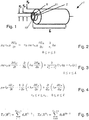
- Fig. 1 shows the first preferred embodiment of a latent heat storage device 1 with a hollow cylindrical latent heat storage structure element 11, which serves as a tube for the heat transfer fluid 8, and also forms the inner wall between the heat transfer fluid 8 and the phase change material 2.
- the latent heat storage structure element 11 has an inner radius r i and an outer radius r o .
- the phase change material 2 which is also in the form of a hollow cylinder and has the inner radius r o and the outer radius r e and the length L, is arranged coaxially around the latent heat storage structure element 11.
- the energy balance equations can be given in a cylindrical coordinate system.
- the energy balance equation of the first preferred embodiment for the heat transfer fluid 8 is shown in FIG Fig. 2 shown, the index H of the thermodynamic variables relating to the heat transfer fluid 8.
- the energy balance equation of the first preferred embodiment for the Latent heat storage structure element 11 is shown in FIG Fig. 3 shown, the index W of the thermodynamic variables relating to the latent heat storage structure element 11.
- the energy balance equation of the first preferred embodiment for the phase change material 2 is shown in FIG Fig. 4 shown, wherein the index P of the thermodynamic variables relates to the phase change material 2.
- the apparent specific heat capacity c ⁇ p can in particular be a combination of a sensitive part and a latent part, the latent part being able to be modeled in particular as a scaled distribution function, for example a Gauss or Weibull distribution.
- a local discretization is preferably used for model reduction.
- a combination of the discretization with finite differences for the heat transfer fluid 8 and the discretization with the method of orthogonal collocation for the latent heat storage structure element 11 and the phase change material 2 has proven to be an efficient and therefore preferred variant.
- the in Fig. 5 Approach polynomials shown can be used.
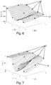
- Fig. 6 an exemplary temperature field 5 for the first preferred embodiment of the latent heat store 1 is shown.
- the latent heat storage device 1 has twelve temperature sensors 4, the positions 3 being arranged at four different points along the length and on the inside, middle and outside of the phase change material 2.
- a suitable temperature field 5 for these twelve measured temperatures can then be calculated numerically using the energy balance equations.
- the temperature field 5 could be determined with temperature sensors 4 which are only arranged along the length. As a result, the number of temperature sensors 4 could be reduced from twelve to four.
- a dynamic one can be preferred for this State estimators are used, such as a Kalman filter.
- a so-called extended Kalman filter or an unscented Kalman filter can preferably be used as the state estimator.
- a moving horizon estimator could be used as a state estimator
- the state of charge 6 is then determined on the basis of the temperature field 5. It can preferably be provided that the state of charge 6 is a ratio of the phase change material 2 in a first phase state to the sum of the phase change material 2 in the first phase state and a second phase state. If the phase change is between a solid phase state and a liquid phase state, the state of charge 6 can in particular be the ratio of a liquid phase change material 2 to the sum of solid and liquid phase change material 2. It has been shown here that such a definition of the state of charge is particularly meaningful and increases linearly with the stored latent thermal energy.
- a distribution of a local state of charge 6 is determined on the basis of the temperature field 5. The distribution of a local state of charge 6 can in particular be referred to as a state of charge field.
- the state of charge 6 can therefore preferably be determined as a state of charge field of the phase change material 2, the local state of charge 6 preferably being determined with the same local resolution as the temperature field 5.
- the distribution of the local state of charge 6 can in particular be output via the data output unit.
- the local state of charge 6 can be integrated over the volume of the phase change material 2.
- the distribution of the local state of charge 6 in a temperature field according to FIG Fig. 6 is in Fig. 7 shown.
- Providing the distribution of the local state of charge 6 has the advantage over the global state of charge 6 that not only the stored Thermal energy can be determined, but predictions can also be made as to how a charging process or discharging process of the latent heat storage device 1 will take place. If, for example, the phase change material 2 is mainly melted on a side of the phase change material 2 facing the heat transfer fluid 8, with the same global state of charge 6 more thermal energy can be dissipated in a short period of time, as with a uniform distribution of the local state of charge 6 and therefore also the latent thermal energy in the entire phase change material 2. As a result, the control system can recognize how a loading or unloading process will take place in the current state of charge 6, and in particular whether the heat energy required for a process can be completely taken from latent heat storage 1, or whether additional generation of heat energy is necessary is.
- the temperature field 5 is recalculated at predeterminable time intervals. Such a regular recalculation of the temperature field 5 can also be referred to as quasi-continuous.
- the predeterminable time interval can in particular be between 1 hour and 1 second, in particular between 10 min and 10 seconds, wherein the predeterminable time interval can depend in particular on the size of the latent heat storage device 1.
- a change in the measured temperatures over time is used by the computing unit to calculate the temperature field 5 in the phase change material 2.
- two physical measured variables are available which can be used for comparison with the calculated temperature field 5, namely the temperature itself but also the change over time, that is to say the derivative, of the temperature. This doubles if the number remains the same Temperature sensor 4, the measured values that are available for calculating the temperature field 5, whereby the calculated temperature field 5 can be calculated with an even smaller error, or the same accuracy can be achieved with fewer temperature sensors 4.
- the temperature-dependent behavior of the phase change material 2 which is preferably available as caloric data, can be taken into account.
- Fig. 8 the apparent specific heat capacity c ⁇ p of a phase change material 2 is shown as a function of the temperature at which the phase transition takes place within a temperature range.
- Fig. 9 the latent part ⁇ of the heat capacity is shown, which is the hatched area in Fig. 8 corresponds.
- Fig. 10 an integral representation of the latent component ⁇ of the heat capacity is shown, which is normalized to 1 and which corresponds to the state of charge 6.
- the ordinate axis is labeled soc for "state of charge”.
- the function shown represents an ideal state which is bijective and can therefore be deduced directly from a temperature to a state of charge.
- phase change from the first phase state to the second phase state often takes place according to a different curve than the reverse phase change, as exemplified in FIG Fig. 11 is indicated, or with a time delay.
- Such hysteresis-like effects are often caused by overheating or undercooling of the phase change material 2.
- a phase change does not take place suddenly in reality, but only after a certain time, for example because crystal growth takes a certain amount of time.
- a previous state of charge 6 of the phase change material 2 is included in order to determine the state of charge 6 on the basis of the temperature field 5.
- the previous state of charge 6 is here a state of charge 6 already determined in a previous measurement.
- the previous state of charge 6 can preferably the immediately preceding, i.e. last available, charge level 6.
- the time profile of the change in the state of charge 6 and thus also a time-dependent or direction-dependent behavior of the phase change material 2 can also be taken into account.
- the time-dependent or direction-dependent behavior of the phase change material 2 can be present as part of the caloric data of the phase change material 2, in particular be stored. As a result, the determination of the state of charge 6 can also be improved in a simple manner and without additional sensors.
- both the previous state of charge 6 and the change in the temperature field 5 over time can be included for determining the state of charge 6. This enables a particularly precise determination of the state of charge 6.
- a heat supply into the latent heat store 1 and a heat dissipation from the latent heat store 1 are measured and used by the computing unit to calculate the temperature field 5 in the phase change material 2.
- the heat supply and the heat removal can take place in particular by means of the heat transfer fluid 8.
- the latent heat store 1 has an inflow 10 and an outflow for a heat transfer fluid 8, and a sensor for determining the heat energy supplied and the heat energy removed is arranged in the inflow 10 and outflow.
- the sensors for determining the supplied thermal energy and the removed thermal energy can in particular have a flow sensor and a further temperature sensor for measuring the temperature of the heat transfer fluid 8.
- the latent heat accumulator 1 has less than 40, in particular less than 20, particularly preferably less than 10, Has temperature sensors 4.
- the temperature would be measured at less than 40, in particular less than 20, particularly preferably less than 10, positions 3.
- the number of temperature sensors 4 required can be kept at an economically reasonable low number.
- the latent heat storage device 1 has more than 3, preferably more than 5, temperature sensors 4.
- the temperature sensors 4 are essentially in direct contact with the phase change material 2.
- the essentially direct contact means that between the temperature sensor 4, or its measuring sensor, and the phase change material 2, only a separating layer with good thermal conductivity can be arranged. As a result, the temperature of the phase change material 2 can be measured as quickly as possible.
- the temperature sensors 4 are arranged in an outer shell of the latent heat storage device 1. As a result, it is also possible to retrofit existing latent heat storage devices 1 at a later date.
- the temperature sensors 4 can be arranged in the phase change material 2 according to the specification of the optimal support points of the selected approach polynomials. In particular, positions 3 can be determined after evaluating the orthogonality conditions of the approach polynomials. This determination has to take place during the construction of the latent heat store 1.
- Figs. 13 to 16 some preferred embodiments of the arrangement of temperature sensors are shown in some common geometric components of latent heat storage 1.
- Fig. 13 shows a plate heat exchanger arrangement with phase change material 2 overflowing on both sides.
- the temperature sensors 4 can be arranged in the middle of the phase change material 2 in particular.
- Fig. 14 shows a plate heat exchanger arrangement with a phase change material 2 overflowing on one side, with one of the The side facing away from the heat transfer fluid 8 is an insulation material 12.
- the temperature sensors 4 can be arranged in particular at the transition from the phase change material 2 to the insulation material 12, since heat removal via the insulation material 12 is usually negligible.
- Fig. 15 a tubular heat exchanger arrangement with a jacket made of a phase change material 2 is shown.
- the temperature sensors 4 can be arranged centrally in the phase change material 2.
- FIG. 13 is a shell and tube heat exchanger arrangement with multiple tube heat exchanger arrangements as in FIG Fig. 15 shown.
- the temperature sensors 4 can be arranged at the contact points of the individual tubes with one another.
- the phase change material 2 is divided into several sectors 9 for the calculation of the temperature field 5 along a flow direction 7 of a heat transfer fluid 8, and that only one measured temperature is used for the calculation of the temperature field 5 per sector 9.
- the temperature sensors 4 are arranged along a flow direction 7 of the heat transfer fluid 8.
- the latent heat accumulator 1 is preferably segmented along the flow direction 7 of the heat transfer fluid 8 according to the balance sheet. As a result, the number of temperature sensors 4 and the associated measurement complexity can be kept low.
- An exemplary approach to segmenting the latent heat storage device 1 along the flow direction 7 with the arrangement of the temperature sensors 4 is shown in FIG Fig. 12 shown.
- one of the temperature sensors 4 has a plurality of measuring sensors, the measured temperature of the temperature sensor 4 being an average of measured values from the measuring sensors.
- the measuring sensors can be arranged at different points at which the same temperature can be expected. The measured value of the sensors is then averaged in order to determine the measured temperature. Such an arrangement can reduce any measurement errors of the individual measuring sensors.
Landscapes
- Engineering & Computer Science (AREA)
- Physics & Mathematics (AREA)
- Thermal Sciences (AREA)
- Mechanical Engineering (AREA)
- General Engineering & Computer Science (AREA)
- Central Heating Systems (AREA)
- Investigating Or Analyzing Materials Using Thermal Means (AREA)
Description
Die Erfindung betrifft ein Verfahren zum Bestimmen eines Ladezustandes eines Latentwärmespeichers gemäß dem Patentanspruch 1.The invention relates to a method for determining a state of charge of a latent heat storage device according to
Latentwärmespeicher sind Speicher für thermische Energie, bei welchen die Wärme in Form von latenter Energie bei einem Phasenwechsel gespeichert wird. Die Bestimmung des Ladezustandes eines Latentwärmespeichers, insbesondere die Frage der noch aufnehmbaren Wärmeenergie, hat sich hierbei als schwierig herausgestellt.Latent heat stores are stores for thermal energy in which the heat is stored in the form of latent energy during a phase change. The determination of the state of charge of a latent heat accumulator, in particular the question of the heat energy that can still be absorbed, has turned out to be difficult.
Eine Bestimmung des Ladezustandes kann dadurch erfolgen, dass das Phasenwechselmaterial in einem thermischen Gleichgewicht zu einem Wärmeträgerfluid ist, und von der Temperatur des Wärmeträgerfluids auf die Temperatur des Phasenwechselmaterials geschlossen wird. Nachteilig daran ist, dass dieses Verfahren lediglich dann hinreichend genau ist, wenn die Menge des Wärmeträgerfluids die Menge an Phasenwechselmaterial deutlich übersteigt. Bei kompakteren Ausführungen eines Latentwärmespeichers ist diese Methode daher unzureichend.The state of charge can be determined in that the phase change material is in thermal equilibrium with a heat transfer fluid and the temperature of the phase change material is deduced from the temperature of the heat transfer fluid. The disadvantage of this is that this method is only sufficiently accurate when the amount of heat transfer fluid clearly exceeds the amount of phase change material. This method is therefore inadequate for more compact versions of a latent heat storage device.
Eine weitere Möglichkeit der Bestimmung des Ladezustandes kann durch die Bestimmung von Parametern wie den Druck erfolgen, welcher je nach Zustand des Phasenwechselmaterials einen für den gesamten Latentwärmespeicher gültigen Wert angibt. Nachteilig an dieser Methode ist allerdings der vergleichsweise erhöhte Aufwand zur Kalibrierung und die ungenauere Messmethode.Another possibility of determining the state of charge can be done by determining parameters such as the pressure, which, depending on the state of the phase change material, indicates a value that is valid for the entire latent heat storage device. The disadvantage of this method, however, is the comparatively increased effort required for calibration and the less precise measurement method.
Aus der
Aus der
Aus der
Aufgabe der Erfindung ist es daher ein Verfahren der eingangs genannten Art anzugeben, mit welchem die genannten Nachteile vermieden werden können, mit welchem es möglich ist den Ladezustand eines Latentwärmespeichers einfach und mit hoher Genauigkeit zu bestimmen.The object of the invention is therefore to provide a method of the type mentioned at the beginning with which the mentioned disadvantages can be avoided, with which it is possible to determine the state of charge of a latent heat accumulator simply and with high accuracy.
Erfindungsgemäß wird dies durch die Merkmale des Patentanspruches 1 erreicht.According to the invention, this is achieved by the features of
Dadurch ergibt sich der Vorteil, dass der Ladezustand eines Latentwärmespeichers einfach und mit hoher Genauigkeit bestimmt werden kann. Hierbei kann aufgrund der Messung der Temperatur an wenigen Stellen ein Temperaturfeld innerhalb des Phasenwechselmaterials berechnet werden, und anschließend aufgrund des berechneten Temperaturfeldes zuverlässig auf den Ladezustand geschlossen werden. Dadurch kann auch der Ladezustand von kompakten und/oder komplexen Latentwärmespeicher, in welchen es zu großen Differenzen der Temperatur innerhalb des Phasenwechselmaterials kommen kann, zuverlässig bestimmt werden. Durch die Verwendung von Temperatursensoren ist das Verfahren seitens der Messtechnik einfach durchführbar. Weiters kann der Latentwärmespeicher schnell mit Wärmeenergie be- und entladen werden, da das Einstellen eines Equilibriums nicht zur Bestimmung des Ladezustandes abgewartet werden muss. Da der Ladezustand schnell und zuverlässig bestimmt werden kann, kann ein mit diesem Verfahren überwachter Latentwärmespeicher auch in komplexeren Regelsystemen eingesetzt werden, insbesondere in der Regelung der Bereitstellung von Wärmeenergie in einem Gebäude, bevorzugt Niederenergiehaus oder Passivhaus, oder von industrieller Prozesswärme, insbesondere Dampfnetze, Thermoölanlagen und/oder der Bereitstellung von Heißwasser. Dadurch kann ein mit diesem Verfahren überwachter Latentwärmespeicher helfen, die Erzeugung von Wärmeenergie, und einen damit verbundenen Ausstoß an Treibhausgasen, zu vermeiden.This has the advantage that the state of charge of a latent heat storage device can be determined easily and with high accuracy. Here, based on the measurement of the temperature at a few points, a temperature field within the phase change material can be calculated, and then based on the calculated temperature field, conclusions can be drawn reliably about the state of charge. As a result, the state of charge of compact and / or complex latent heat accumulators, in which large differences in temperature within the phase change material can occur, can also be reliably determined. By using temperature sensors, the process can be carried out easily by measurement technology. Furthermore, the latent heat storage device can be quickly charged and discharged with thermal energy, since the setting of an equilibrium does not have to be waited for to determine the state of charge. Since the state of charge can be determined quickly and reliably, a latent heat storage device monitored with this method can also be used in more complex control systems, in particular in the control of the provision of thermal energy in a building, preferably a low-energy house or passive house, or of industrial process heat, in particular steam networks, thermal oil systems and / or the provision of hot water. This allows a Latent heat storage systems monitored with this method help to avoid the generation of thermal energy and the associated emission of greenhouse gases.
Weiters betrifft die Erfindung einen Latentwärmespeicher gemäß dem Patentanspruch 8.The invention also relates to a latent heat storage device according to
Aufgabe der Erfindung ist es daher weiters einen Latentwärmespeicher der eingangs genannten Art anzugeben, mit welchem die genannten Nachteile vermieden werden können, mit welchem es möglich ist den Ladezustand einfach und mit hoher Genauigkeit zu bestimmen.The object of the invention is therefore also to provide a latent heat storage device of the type mentioned at the beginning with which the mentioned disadvantages can be avoided, with which it is possible to determine the state of charge simply and with high accuracy.
Erfindungsgemäß wird dies durch die Merkmale des Patentanspruches 8 erreicht. Die Vorteile des Latentwärmespeichers entsprechend den Vorteilen des Verfahrens zum Bestimmen des Ladezustandes des Latentwärmespeichers.According to the invention, this is achieved by the features of
Die Unteransprüche betreffen weitere vorteilhafte Ausgestaltungen der Erfindung. Ausdrücklich wird hiermit auf den Wortlaut der Patentansprüche Bezug genommen, wodurch die Ansprüche an dieser Stelle durch Bezugnahme in die Beschreibung eingefügt sind und als wörtlich wiedergegeben gelten.The subclaims relate to further advantageous embodiments of the invention. Express reference is hereby made to the wording of the patent claims, whereby the claims are inserted into the description at this point by reference and are considered to be reproduced literally.
Die Erfindung wird unter Bezugnahme auf die beigeschlossenen Zeichnungen, in welchen lediglich bevorzugte Ausführungsformen beispielhaft dargestellt sind, näher beschrieben. Dabei zeigt:
-
Fig. 1 eine erste bevorzugte Ausführungsform eines Latentwärmespeichers in einer axonometrischen Darstellung; -
Fig. 2 eine Energiebilanzgleichung eines Wärmeträgerfluids der ersten bevorzugten Ausführungsform des Latentwärmespeichers; -
Fig. 3 eine Energiebilanzgleichung einer Innenwand der ersten bevorzugten Ausführungsform des Latentwärmespeichers; -
Fig. 4 eine Energiebilanzgleichung eines Phasenwechselmaterials der ersten bevorzugten Ausführungsform des Latentwärmespeichers; -
Fig. 5 Ansatzpolynome für die Energiebilanzgleichungen inFig. 2 bis 4 ; -
Fig. 6 ein errechnetes Temperaturfeld für die erste bevorzugte Ausführungsform; -
Fig. 7 ein aus dem Temperaturfeld inFig. 6 bestimmte Verteilung eines lokalen Ladezustandes; -
Fig. 8 eine scheinbare spezifische Wärmekapazität eines Phasenwechselmaterials als Funktion der Temperatur; -
Fig. 9 einen latenten Anteil der spezifischen Wärmekapazität ausFig. 8 ; -
Fig. 10 ein Integral des latenten Anteils der spezifischen Wärmekapazität eines Phasenwechselmaterials ausFig. 9 ; -
Fig. 11 die Funktion ausFig. 10 mit einem Hystereseeffekt; -
Fig. 12 die erste bevorzugte Ausführungsform des Latentwärmespeichers in einer Explosionsdarstellung; -
Fig. 13 eine erste bevorzugte Anordnung eines Temperatursensors als Prinzipskizze; -
Fig. 14 eine zweite bevorzugte Anordnung eines Temperatursensors als Prinzipskizze; -
Fig. 15 eine dritte bevorzugte Anordnung eines Temperatursensors als Prinzipskizze; und -
Fig. 16 eine vierte bevorzugte Anordnung eines Temperatursensors als Prinzipskizze.
-
Fig. 1 a first preferred embodiment of a latent heat storage in an axonometric representation; -
Fig. 2 an energy balance equation of a heat transfer fluid of the first preferred embodiment of the latent heat store; -
Fig. 3 an energy balance equation of an inner wall of the first preferred embodiment of the latent heat accumulator; -
Fig. 4 an energy balance equation of a phase change material of the first preferred embodiment of the latent heat accumulator; -
Fig. 5 Approach polynomials for the energy balance equations inFigs. 2 to 4 ; -
Fig. 6 a calculated temperature field for the first preferred embodiment; -
Fig. 7 one from the temperature field inFig. 6 certain distribution of a local state of charge; -
Fig. 8 an apparent specific heat capacity of a phase change material as a function of temperature; -
Fig. 9 a latent part of the specific heat capacityFig. 8 ; -
Fig. 10 an integral of the latent part of the specific heat capacity of a phase change materialFig. 9 ; -
Fig. 11 the function offFig. 10 with a hysteresis effect; -
Fig. 12 the first preferred embodiment of the latent heat storage in an exploded view; -
Fig. 13 a first preferred arrangement of a temperature sensor as a schematic diagram; -
Fig. 14 a second preferred arrangement of a temperature sensor as Outline sketch; -
Fig. 15 a third preferred arrangement of a temperature sensor as a schematic diagram; and -
Fig. 16 a fourth preferred arrangement of a temperature sensor as a schematic diagram.
Die
Vorgesehen ist, dass in dem Latentwärmespeicher 1 ein Phasenwechselmaterial 2 im Wesentlichen ortsfest angeordnet ist. Derartige Phasenwechselmaterialien 2 werden oftmals auch als PCM oder Phase-Changing-Material bezeichnet. Hierbei sind eine Vielzahl an Phasenwechselmaterialien 2 mit unterschiedlichen Phasenumwandlungstemperaturen bekannt. Geeignete Phasenwechselmaterialien 2 können insbesondere Polymere oder Salze sein. Je nach Phasenwechselmaterial 2 kann der Phasenübergang an genau einer Temperatur, oder in einem Temperaturbereich stattfinden.It is provided that a
Diese Zustandsänderungen können insbesondere der Phasenübergang des Phasenwechselmaterials 2 zwischen fest und flüssig sein. Die Phasenumwandlungstemperatur kann insbesondere eine Schmelztemperatur oder Erstarrungstemperatur des ersten Phasenwechselmaterials 2 sein.These changes of state can in particular be the phase transition of the
Alternativ kann vorgesehen sein, dass die Zustandsänderung der Übergang zwischen zwei festen Phasenzuständen des Phasenwechselmaterials 2 ist, insbesondere eine Änderung in der Kristallstruktur, bevorzugt zwischen amorph und kristallin.Alternatively, it can be provided that the change of state is the transition between two fixed phase states of the
Die im Wesentlichen ortsfeste Anordnung des Phasenwechselmaterials 2 bedeutet in diesem Zusammenhang, dass das Phasenwechselmaterial 2 auch in einem flüssigen Phasenzustand ausreichend lokalisiert ist, damit dessen Anordnung für die Berechnung eines Temperaturfeldes 5 als statisch angenommen werden kann. Hierbei erfolgt eine Wärmeübertragung im Phasenwechselmaterial 2 im Wesentlichen lediglich durch Wärmeleitung, während eine Wärmeübertragung über Konvektion lediglich lokal erfolgt und vernachlässigbar ist. Die im Wesentlichen ortsfeste Anordnung kann insbesondere durch ortsfeste Kammern erreicht werden, in welchen Kammern das Phasenwechselmaterial 2 angeordnet ist.The essentially stationary arrangement of the
Vorgesehen ist weiters, dass an wenigstens zwei Positionen 3 des Latentwärmespeichers 1 eine Temperatur mittels Temperatursensoren 4 gemessen wird, mit den gemessenen Temperaturen von einer Recheneinheit ein Temperaturfeld 5 in dem Phasenwechselmaterial 2 berechnet wird, und anschließend anhand des Temperaturfeldes 5 ein Ladezustand 6 des Latentwärmespeichers 1 bestimmt wird. Die wenigstens zwei Positionen 3 des Latentwärmespeichers 1 sind thermisch miteinander in Kontakt, also nicht thermisch isoliert, sodass sich aufgrund der Wärmeleitung sich ein Wärmefluss zwischen diesen wenigstens zwei Positionen 3 ausbilden kann. Insbesondere kann vorgesehen sein, dass die wenigstens zwei Positionen 3 in dem gleichen, zusammenhängenden Phasenwechselmaterial 2 angeordnet sind. Aufgrund der gemessenen Temperatur an den wenigstens zwei Positionen 3 kann dann das Temperaturfeld 5, also die örtlich aufgelöste Temperaturverteilung, in dem Phasenwechselmaterial 2 berechnet werden. Aufgrund des Temperaturfeldes 5 kann dann der Ladezustand 6 des Latentwärmespeichers 1 bestimmt werden.Provision is also made for a temperature to be measured by means of temperature sensors 4 at at least two positions 3 of the
Dadurch ergibt sich der Vorteil, dass der Ladezustand eines Latentwärmespeichers 1 einfach und mit hoher Genauigkeit bestimmt werden kann. Hierbei kann aufgrund der Messung der Temperatur an wenigen Stellen ein Temperaturfeld 5 innerhalb des Phasenwechselmaterials 2 berechnet werden, und anschließend aufgrund des berechneten Temperaturfeldes 5 zuverlässig auf den Ladezustand 6 geschlossen werden. Dadurch kann auch der Ladezustand 6 von kompakten und/oder komplexen Latentwärmespeicher 1, in welchen es zu großen Differenzen der Temperatur innerhalb des Phasenwechselmaterials 2 kommen kann, zuverlässig bestimmt werden. Durch die Verwendung von Temperatursensoren 4 ist das Verfahren seitens der Messtechnik einfach durchführbar. Weiters kann der Latentwärmespeicher 1 schnell mit Wärmeenergie be- und entladen werden, da das Einstellen eines Equilibriums nicht zur Bestimmung des Ladezustandes 6 abgewartet werden muss. Da der Ladezustand 6 schnell und zuverlässig bestimmt werden kann, kann ein mit diesem Verfahren überwachter Latentwärmespeicher 1 auch in komplexeren Regelsystemen eingesetzt werden, insbesondere in der Regelung der Bereitstellung von Wärmeenergie in einem Gebäude, bevorzugt Niederenergiehaus oder Passivhaus, oder von industrieller Prozesswärme, insbesondere Dampfnetze, Thermoölanlagen und/oder der Bereitstellung von Heißwasser. Dadurch kann ein mit diesem Verfahren überwachter Latentwärmespeicher 1 helfen, die Erzeugung von Wärmeenergie, und einen damit verbundenen Ausstoß an Treibhausgasen, zu vermeiden.This has the advantage that the state of charge of a latent
Für die Berechnung des Temperaturfeldes 5 kann insbesondere die örtliche Anordnung des Phasenwechselmaterials 2 verwendet werden. Ein Modell der Form und Lage des Phasenwechselmaterials 2 kann insbesondere in der Recheneinheit abgespeichert sein.In particular, the local arrangement of the
Für die Berechnung des Temperaturfeldes 5 können insbesondere die kalorischen Daten des Phasenwechselmaterials 2 verwendet werden. Die kalorischen Daten des Phasenwechselmaterials 2 können insbesondere in der Recheneinheit abgespeichert sein. Die kalorischen Daten des Phasenwechselmaterials 2 betreffen insbesondere dessen spezifische Wärmekapazität. Diese kalorischen Daten können aus Datenblättern entnommen werden und/oder experimentell bestimmt werden.In particular, the caloric data of the
Das Phasenwechselmaterial 2 des Latentwärmespeichers 1 kann insbesondere homogen sein, also lediglich aus einem Material mit den gleichen kalorischen Daten bestehen.The
Alternativ kann vorgesehen sein, dass das Phasenwechselmaterial 2 des Latentwärmespeichers 1 mehrere Materialien mit unterschiedlichen kalorischen Daten aufweist, beispielsweise verschiedene Phasenumwandlungstemperaturen. Das Modell der Form und Lage des Phasenwechselmaterials 2 in der Recheneinheit kann hierbei ebenfalls die Aufteilung der unterschiedlichen Materialien beinhalten.Alternatively, it can be provided that the
Weiters ist ein Latentwärmespeicher 1 umfassend das, im Wesentlichen ortsfest angeordneten Phasenwechselmaterial 2 vorgesehen, wobei an den wenigstens zwei Positionen 3 des Latentwärmespeichers 1 die Temperatursensoren 4 angeordnet sind, wobei die Temperatursensoren 4 schaltungstechnisch mit der Recheneinheit zur Bestimmung eines Ladezustandes 6 des Latentwärmespeichers 1 verbunden sind, wobei zur Bestimmung des Ladezustandes 6 von der Recheneinheit anhand von den gemessenen Temperaturen der Temperatursensoren 4 das Temperaturfeld 5 in dem Phasenwechselmaterial 2 berechnet, und anhand des Temperaturfeldes 5 der Ladezustand 6 des Latentwärmespeichers 1 bestimmt wird.Furthermore, a latent
Die, in den Fig. nicht dargestellte, Recheneinheit kann insbesondere elektronisch sein, und bevorzugt einen Prozessor umfassen.The arithmetic unit, not shown in the figures, can in particular be electronic and preferably comprise a processor.
Die Recheneinheit kann insbesondere getrennt von dem restlichen Latentwärmespeicher 1 angeordnet sein, und über Datenkabel oder Funk schaltungstechnisch mit den Temperatursensoren 4 verbunden sein.The computing unit can in particular be arranged separately from the remaining latent
Die Recheneinheit kann insbesondere eine Datenausgabeeinheit aufweisen, welche Daten bezüglich des Ladezustands 6 kabelgebunden und/oder mittels Funk sendet. Dadurch können die Daten bezüglich des Ladezustandes 6 in ein Regelsystem eingebunden werden.The arithmetic unit can in particular have a data output unit which sends data relating to the state of
Insbesondere kann der Ladezustand 6 des Latentwärmespeichers 1 für die Regelung eines Steuerungssystems zur Bereitstellung von Wärmeenergie verwendet werden. Das Steuerungssystem kann insbesondere ein prädiktives Regelungssystem sein.In particular, the state of
Das Steuerungssystem kann insbesondere zur Bereitstellung von Wärmeenergie in einem Gebäude verwendet werden. Durch die genaue Bestimmung des Ladezustandes 6 des Latentwärmespeichers 1 kann das Steuerungssystem beispielsweise vorhersagen, ob die gespeicherte Wärmeenergie ausreichend ist um einen Zeitraum mit hohen Energiekosten zu überbrücken, oder ob zusätzliche Wärmeenergie benötigt wird. Dadurch kann im Sinne intelligenter Energiesysteme der Energieverbrauch auf Zeitpunkte mit üblicherweise geringer Last verschoben werden, wodurch Kosten und Umweltbelastung gering gehalten werden können.The control system can in particular be used to provide thermal energy in a building. By precisely determining the state of
Eine derartige Steuerung kann sowohl im Bereich eines Gebäudes mit Privatwohnungen aber auch in Industriebetrieben zum Einsatz kommen.Such a control can be used both in the area of a building with private apartments and in industrial companies.
Weiters kann vorgesehen sein, dass die Recheneinheit mit einer Anzeigeeinheit schaltungstechnisch verbunden ist.Furthermore, it can be provided that the computing unit is connected to a display unit in terms of circuitry.
Gemäß einer bevorzugten Ausführungsform, welche besonders einfach ausgebildet ist, kann vorgesehen sein, dass das Temperaturfeld 5 zwischen den Positionen 3 durch lineare Interpolation berechnet wird. Dadurch kann der Rechenaufwand gering gehalten werden, wobei größere Abweichungen zwischen dem berechneten Temperaturfeld 5 und der Realität vorhanden sein können.According to a preferred embodiment, which is particularly simple, it can be provided that the
Besonders bevorzugt kann vorgesehen sein, dass zur Berechnung des Temperaturfeldes 5 zumindest für das Phasenwechselmaterial 2 eine Energiebilanzgleichung erstellt wird. Durch die Energiebilanzgleichung zumindest des Phasenwechselmaterials 2 kann anhand der Wärmeleitung und der spezifischen Wärmekapazität ein Modell für ein, der Realität nachempfundenes Temperaturfeld 5 in dem Phasenwechselmaterial 2 berechnet, und an die gemessenen Temperaturen angepasst werden. Dadurch ist eine Berechnung des Temperaturfeldes 5 wesentlich genauer und realistischer als bei einer linearen Interpolation, beziehungsweise erreicht mit weniger Temperatursensoren 4 eine gleich hohe Genauigkeit.It can particularly preferably be provided that an energy balance equation is created for calculating the
Der Latentwärmespeicher 1 kann insbesondere von eignem Wärmeträgerfluid 8 durchflossen werden. Das Wärmeträgerfluid 8 dient zur Zufuhr und/oder Abfuhr von Wärmeenergie in oder aus dem Latentwärmespeicher 1. Das Wärmeträgerfluid 8 kann insbesondere Wasser sein.The latent
Der Latentwärmespeicher 1 kann weiters festes Latentwärmespeicherstrukturelemente 11 aufweisen. Latentwärmespeicherstrukturelemente 11 sind ortsfeste Strukturen innerhalb des Latentwärmespeichers 1, welche wärmeleitend sind, und im Betriebstemperaturbereich des Latentwärmespeichers 1 keinen Phasenwechsel vollziehen. Die Latentwärmespeicherstrukturelemente 11 können insbesondere Innenwände zwischen dem Wärmeträgerfluid 8 und dem Phasenwechselmaterial 2 und/oder Stützkonstruktionen umfassen.The
Die Latentwärmespeicherstrukturelemente 11 können insbesondere als Rohre ausgebildet sein.The latent heat
Bevorzugt können mehrere Rohre zu einem Rohrbündel zusammengefasst sein.A plurality of tubes can preferably be combined to form a tube bundle.
Weiters kann vorgesehen sein, dass zur Berechnung des Temperaturfeldes 5 für das Wärmeträgerfluid 8 und/oder die Latentwärmespeicherstrukturelemente 11 eine Energiebilanzgleichung erstellt wird. Dadurch können auch diese Randbedingungen in die Berechnung des Temperaturfeldes 5 einbezogen werden.Furthermore, it can be provided that an energy balance equation is created for calculating the
Eine bevorzugte Vorgehensweise der Berechnung des Temperaturfeldes 5 wird im folgenden anhand der einfachen Geometrie der ersten bevorzugten Ausführungsform in
Die Energiebilanzgleichung der ersten bevorzugten Ausführungsform für das Wärmeträgerfluid 8 ist in
Die Energiebilanzgleichung der ersten bevorzugten Ausführungsform für das Latentwärmespeicherstrukturelement 11 ist in
Die Energiebilanzgleichung der ersten bevorzugten Ausführungsform für das Phasenwechselmaterial 2 ist in
Zur Modellreduktion wird bevorzugt eine örtliche Diskretisierung verwendet. Als effiziente und daher bevorzugte Variante hat sich hierbei eine Kombination der Diskretisierung mit finiten Differenzen für das Wärmeträgerfluid 8, und der Diskretisierung mit dem Verfahren der Orthogonalen Kollokation für das Latentwärmespeicherstrukturelement 11 und das Phasenwechselmaterial 2 gezeigt. Für die Orthogonale Kollokation können insbesondere die in
In
Alternativ könnte das Temperaturfeld 5 mit Temperatursensoren 4 bestimmt werden, welche lediglich entlang der Länge angeordnet sind. Dadurch könnte die Anzahl der Temperatursensoren 4 von zwölf auf vier reduziert werden.Alternatively, the
Bevorzugt ist vorgesehen, dass für eine quasi kontinuierliche Bestimmung des Ladezustandes 6 das Temperaturfeld 5 den gemessenen Temperaturen der Temperatursensoren 4 nachgeführt wird. Bevorzugt kann hierfür ein dynamischer Zustandsschätzer eingesetzt werden, wie beispielsweise ein Kalman Filter. Als Zustandsschätzer können bevorzugt ein sogenannter Extended Kalman Filter oder ein Unscented Kalman Filter eingesetzt werden. Weiters könnte ein Moving Horizon Schätzer als Zustandsschätzer eingesetzt werdenProvision is preferably made for the
Weiters kann eine Linearisierung der Energiebilanzgleichungen für den Einsatz von linearen Schätzern durchgeführt werden.Furthermore, the energy balance equations can be linearized for the use of linear estimators.
Anhand des Temperaturfeldes 5 wird anschließend der Ladezustand 6 bestimmt. Bevorzugt kann vorgesehen sein, dass der Ladezustand 6 ein Verhältnis des Phasenwechselmaterials 2 in einem ersten Phasenzustand zu der Summe des Phasenwechselmaterials 2 in dem ersten Phasenzustand und einem zweiten Phasenzustand ist. Sofern der Phasenwechsel zwischen einem festen Phasenzustand und einem flüssigen Phasenzustand ist, kann der Ladezustand 6 insbesondere das Verhältnis von einem flüssigen Phasenwechselmaterial 2 zu der Summe aus festen und flüssigen Phasenwechselmaterial 2 sein. Hierbei hat sich gezeigt, dass eine derartige Definition des Ladezustandes besonders aussagekräftig ist und linear mit der gespeicherten latenten Wärmeenergie ansteigt. Anhand des Temperaturfeldes 5 wird eine Verteilung eines lokalen Ladezustandes 6 bestimmt. Die Verteilung eines lokalen Ladezustandes 6 kann insbesondere als Ladezustandsfeld bezeichnet werden. Der Ladezustand 6 kann daher bevorzugt als Ladezustandsfeld des Phasenwechselmaterials 2 bestimmt werden, wobei der lokale Ladezustand 6 bevorzugt mit derselben örtlichen Auflösung wie das Temperaturfeld 5 bestimmt wird. Die Verteilung des lokalen Ladezustandes 6 kann insbesondere über die Datenausgabeeinheit ausgegeben werden. Um einen globalen Ladezustand 6 des gesamten Phasenwechselmaterials 2 zu bestimmen kann der lokale Ladezustand 6 über das Volumen des Phasenwechselmaterials 2 integriert werden. Die Verteilung des lokalen Ladezustandes 6 bei einem Temperaturfeld gemäß
Die Bereitstellung der Verteilung des lokalen Ladezustandes 6 hat gegenüber dem globalen Ladezustand 6 den Vorteil, dass anhand dieser nicht nur die gespeicherte Wärmeenergie bestimmt werden kann, sondern auch Vorhersagen getroffen werden können, wie ein Beladevorgang oder Entladevorgang des Latentwärmespeichers 1 erfolgen wird. Wenn beispielsweise das Phasenwechselmaterial 2 hauptsächlich an einer dem Wärmeträgerfluid 8 zugewandten Seite des Phasenwechselmaterials 2 geschmolzen ist, kann bei einem gleichen globalen Ladezustand 6 mehr Wärmeenergie in einer kurzen Zeitspanne abgeführt werden, wie bei einer gleichmäßigen Verteilung des lokalen Ladezustands 6 und daher auch der latenten Wärmeenergie im gesamten Phasenwechselmaterial 2. Dadurch kann das Steuerungssystem erkennen, wie beim derzeitigen Ladezustand 6 ein Beladevorgang oder Entladevorgang ablaufen wird, und insbesondere, ob die benötigte Wärmeenergie für einen Prozess aus dem Latentwärmespeicher 1 komplett entnommen werden kann, oder ob eine zusätzliche Erzeugung von Wärmeenergie notwendig ist.Providing the distribution of the local state of
Besonders bevorzugt kann vorgesehen sein, dass das Temperaturfeld 5 in vorgebbaren zeitlichen Abständen neu berechnet wird. Eine derartige regelmäßige Neuberechnung des Temperaturfeldes 5 kann auch als quasi kontinuierlich bezeichnet werden.It can particularly preferably be provided that the
Der vorgebbare zeitliche Abstand kann insbesondere zwischen 1 Stunde und 1 Sekunde, insbesondere zwischen 10 min und 10 Sekunden, betragen, wobei der vorgebbare zeitliche Abstand insbesondere von der Größe des Latentwärmespeichers 1 abhängen kann.The predeterminable time interval can in particular be between 1 hour and 1 second, in particular between 10 min and 10 seconds, wherein the predeterminable time interval can depend in particular on the size of the latent
Bevorzugt kann weiters vorgesehen sein, dass durch einen Vergleich des Temperaturfeldes 5 mit dem vorangegangenen Temperaturfeld 5 eine zeitliche Änderung der berechneten Temperaturen erstellt wird.It can also preferably be provided that a comparison of the
Besonders bevorzugt kann vorgesehen sein, dass eine zeitliche Änderung der gemessenen Temperaturen von der Recheneinheit zur Berechnung des Temperaturfeldes 5 in dem Phasenwechselmaterial 2 verwendet wird. Somit stehen pro Temperatursensor 4 zwei physikalische Messgrößen zur Verfügung, welche zum Abgleich mit dem berechneten Temperaturfeld 5 verwendet werden können, nämlich die Temperatur an sich aber auch die zeitliche Änderung, also Ableitung, der Temperatur. Dadurch verdoppelt sich bei einer gleichbleibenden Anzahl an Temperatursensor 4 die Messwerte, welche zur Berechnung des Temperaturfeldes 5 zur Verfügung stehen, wodurch das berechnete Temperaturfeld 5 mit einem noch geringeren Fehler berechnet werden kann, beziehungsweise kann eine gleiche Genauigkeit mit weniger Temperatursensoren 4 erreicht werden.It can particularly preferably be provided that a change in the measured temperatures over time is used by the computing unit to calculate the
Bei der Bestimmung des Ladezustandes 6 kann das temperaturabhängige Verhalten des Phasenwechselmaterials 2 berücksichtigt werden, welches bevorzugt als kalorische Daten vorliegt.When determining the state of
In
In
In
In der Realität ist dieser direkte Zusammenhang oft nicht unmittelbar gegeben, sondern der Phasenwechsel von dem ersten Phasenzustand zu dem zweiten Phasenzustand erfolgt oft nach einer anderen Kurve als der umgekehrte Phasenwechsel, wie dies beispielhaft in
Insbesondere kann vorgesehen sein, dass für die Bestimmung des Ladezustandes 6 anhand des Temperaturfeldes 5 ein vorangegangener Ladezustand 6 des Phasenwechselmaterials 2 miteinbezogen wird. Der vorangegangene Ladezustand 6 ist hierbei ein bei einer vorigen Messung bereits bestimmter Ladezustand 6. Bei einem quasi kontinuierlichen Betrieb kann der vorangegangene Ladezustand 6 bevorzugt der unmittelbar vorangegangene, also letzte vorhandene, Ladezustand 6 sein. Dadurch können bei der Bestimmung des Ladezustandes 6 der zeitliche Verlauf der Änderung des Ladezustandes 6, und somit auch ein zeitabhängiges oder richtungsabhängiges Verhalten des Phasenwechselmaterials 2 mitberücksichtigt werden. Das zeitliche oder richtungsabhängige Verhalten des Phasenwechselmaterials 2 kann als Teil der kalorischen Daten des Phasenwechselmaterials 2 vorliegen, insbesondere abgespeichert sein. Dadurch kann ebenfalls auf einfache Weise und ohne zusätzliche Sensorik die Bestimmung des Ladezustandes 6 zusätzlich verbessert werden.In particular, it can be provided that a previous state of
Besonders bevorzugt kann für die Bestimmung des Ladezustandes 6 sowohl der vorangegangene Ladezustand 6 als auch die zeitliche Änderung des Temperaturfeldes 5 miteinbezogen werden. Dadurch kann eine besonders genaue Bestimmung des Ladezustandes 6 erfolgen.Particularly preferably, both the previous state of
Bevorzugt kann weiters vorgesehen sein, dass eine Wärmezufuhr in den Latentwärmespeicher 1 und eine Wärmeabfuhr aus dem Latentwärmespeicher 1 gemessen, und von der Recheneinheit zur Berechnung des Temperaturfeldes 5 in dem Phasenwechselmaterial 2 verwendet wird. Die Wärmezufuhr und die Wärmeabfuhr können insbesondere mittels dem Wärmeträgerfluid 8 erfolgen. Durch die Messung der Wärmezufuhr in den Latentwärmespeicher 1 und eine Wärmeabfuhr aus dem Latentwärmespeicher 1 kann einfach die Genauigkeit der Berechnung verbessert werden.It can also preferably be provided that a heat supply into the
Bei dem Latentwärmespeicher 1 kann vorgesehen sein, dass der Latentwärmespeicher 1 einen Zufluss 10 und einem Abfluss für ein Wärmeträgerfluid 8 aufweist, und dass beim Zufluss 10 und beim Abfluss ein Sensor zur Bestimmung der zugeführten Wärmeenergie und der abgeführten Wärmeenergie angeordnet ist. Die Sensoren zur Bestimmung der zugeführten Wärmeenergie und der abgeführten Wärmeenergie können insbesondere einen Durchflusssensor und einen weiteren Temperatursensor zur Messung der Temperatur des Wärmeträgerfluids 8 aufweisen.In the case of the
Bevorzugt kann vorgesehen sein, dass der Latentwärmespeicher 1 weniger als 40, insbesondere weniger als 20, besonders bevorzugt weniger als 10, Temperatursensoren 4 aufweist. Hierbei würde die Temperatur an weniger als 40, insbesondere weniger als 20, besonders bevorzugt weniger als 10, Positionen 3 gemessen werden. Dadurch kann die Zahl der benötigten Temperatursensoren 4 auf eine wirtschaftlich vernünftige geringe Anzahl gehalten werden.It can preferably be provided that the
Weiters kann vorgesehen sein, dass der Latentwärmespeicher 1 mehr als 3, bevorzugt mehr als 5, Temperatursensoren 4 aufweist.Furthermore, it can be provided that the latent
Insbesondere kann vorgesehen sein, dass zumindest 2 der Temperatursensoren 4 einen im Wesentlichen unmittelbaren Kontakt zu dem Phasenwechselmaterial 2 haben. Der im Wesentlichen unmittelbare Kontakt bedeutet in diesem Zusammenhang, dass zwischen dem Temperatursensor 4, beziehungsweise dessen Messfühler, und dem Phasenwechselmaterial 2 lediglich eine gut wärmeleitende Trennschicht angeordnet sein kann. Dadurch kann eine möglichst umgehende Messung der Temperatur des Phasenwechselmaterials 2 erfolgen.In particular, it can be provided that at least 2 of the temperature sensors 4 are essentially in direct contact with the
Weiters kann vorgesehen sein, dass die Temperatursensoren 4 in einer Außenhülle des Latentwärmespeichers 1 angeordnet sind. Dadurch ist auch eine nachträgliche Nachrüstung bestehender Latentwärmespeicher 1 möglich.Furthermore, it can be provided that the temperature sensors 4 are arranged in an outer shell of the latent
Die Temperatursensoren 4 können in dem Phasenwechselmaterial 2 nach Vorgabe der optimalen Stützstellen der gewählten Ansatzpolynome angeordnet sein. Insbesondere kann die Ermittlung der Positionen 3 nach Auswertung der Orthogonalitätsbedingungen der Ansatzpolynome erfolgen. Diese Ermittlung hat während der Konstruktion des Latentwärmespeichers 1 zu erfolgen.The temperature sensors 4 can be arranged in the
In den
In
In
In
In
Insbesondere kann vorgesehen sein, dass das Phasenwechselmaterial 2 für die Berechnung des Temperaturfeldes 5 entlang einer Flussrichtung 7 eines Wärmeträgerfluids 8 in mehrere Sektoren 9 unterteilt wird, und dass pro Sektor 9 lediglich eine gemessene Temperatur für die Berechnung des Temperaturfeldes 5 verwendet wird. Bei dem Latentwärmespeicher kann vorgesehen sein, dass die Temperatursensoren 4 entlang einer Flussrichtung 7 des Wärmeträgerfluids 8 angeordnet sind. Bevorzugt erfolgt eine bilanzielle Segmentierung des Latentwärmespeichers 1 entlang der Flussrichtung 7 des Wärmeträgerfluids 8. Dadurch kann die Anzahl der Temperatursensoren 4 und der damit verbundene messtechnische Aufwand gering gehalten werden. Ein beispielhafter Ansatz zur Segmentierung des Latentwärmespeichers 1 entlang der Flussrichtung 7 mit der Anordnung der Temperatursensoren 4 ist in
Weiters kann vorgesehen sein, dass einer der Temperatursensor 4 mehrere Messfühler aufweist, wobei die gemessene Temperatur des Temperatursensors 4 ein Mittelwert von Messwerten der Messfühler ist. Die Messfühler können an unterschiedlichen Stellen angeordnet werden, an welchen mit einer gleichen Temperatur zu rechnen ist. Der Messwert der Messfühler wird dann gemittelt um die gemessene Temperatur zu ermitteln. Durch eine derartige Anordnung können etwaige Messfehler der einzelnen Messfühler reduziert werden.Furthermore, it can be provided that one of the temperature sensors 4 has a plurality of measuring sensors, the measured temperature of the temperature sensor 4 being an average of measured values from the measuring sensors. The measuring sensors can be arranged at different points at which the same temperature can be expected. The measured value of the sensors is then averaged in order to determine the measured temperature. Such an arrangement can reduce any measurement errors of the individual measuring sensors.
Claims (11)
- Method for determining a charge state of a latent heat storage device (1), wherein a phase change material (2) is arranged in a substantially stationary manner in the latent heat storage device (1), wherein a temperature is measured at at least two positions (3) of the latent heat storage device (1) by means of temperature sensors (4), characterized in that a temperature field (5) in the phase change material (2) is calculated by a computing unit with the measured temperatures, and in that a distribution of a local charge state (6) of the phase change material (2) is determined by means of the temperature field (5).
- Method according to claim 1, characterized in that for the calculation of the temperature field (5) an energy balance equation is established at least for the phase change material (2).
- Method according to claim 1 or 2, characterized in that the charge state (6) is a ratio of the phase change material (2) in a first phase state to the sum of the phase change material (2) in the first phase state and a second phase state.
- Method according to one of claims 1 to 3, characterized in that a temporal change of the measured temperatures is used by the computing unit to calculate the temperature field (5) in the phase change material (2).
- Method according to one of claims 1 to 4, characterized in that a previous charge state (6) of the phase change material (2) is also included for determining the charge state (6) by means of the temperature field (5).
- Method according to one of claims 1 to 5, characterized in that a heat supply into the latent heat storage device (1) and a heat dissipation from the latent heat storage device (1) is measured and is used by the computing unit to calculate the temperature field (5) in the phase change material (2).
- Method according to one of claims 1 to 6, characterized in that the phase change material (2) is divided into several sectors (9) along a flow direction (7) of a heat transfer fluid (8) for the calculation of the temperature field (5), and in that only one measured temperature per sector (9) is used for the calculation of the temperature field (5).
- Latent heat storage device (1), comprising a phase change material (2) which is arranged essentially in a fixed position, wherein temperature sensors (4) are arranged at at least two positions (3) of the latent heat storage device (1), wherein the temperature sensors (4) are connected in terms of circuitry to a computing unit for determining a charge state (6) of the latent heat storage device (1), characterized in that, in order to determine the charge state (6), the computing unit calculates a temperature field (5) in the phase change material (2) on the basis of measured temperatures of the temperature sensors (4), and a distribution of a local charge state (6) of the phase change material (2) is determined on the basis of the temperature field (5).
- Latent heat storage device (1) according to claim 8, characterized in that the latent heat storage device (1) has an inflow (10) and an outflow for a heat transfer fluid (8), and in that a sensor for determining a supplied thermal energy and a discharged thermal energy is arranged at the inflow (10) and at the outflow.
- Latent heat storage device (1) according to claim 8 or 9, characterized in that the temperature sensors (4) are arranged along a flow direction (7) of a heat transfer fluid (8).
- Latent heat storage device (1) according to one of claims 8 to 10, characterized in that one of the temperature sensors (4) has a plurality of measuring sensors, wherein the measured temperature of the temperature sensor (4) is an average value of measured values of the measuring sensors.
Applications Claiming Priority (1)
| Application Number | Priority Date | Filing Date | Title |
|---|---|---|---|
| ATA51140/2016A AT518791B1 (en) | 2016-12-14 | 2016-12-14 | METHOD FOR DETERMINING A CHARGING STATE OF A LATENT HEAT STORAGE |
Publications (2)
| Publication Number | Publication Date |
|---|---|
| EP3336473A1 EP3336473A1 (en) | 2018-06-20 |
| EP3336473B1 true EP3336473B1 (en) | 2020-09-02 |
Family
ID=60262832
Family Applications (1)
| Application Number | Title | Priority Date | Filing Date |
|---|---|---|---|
| EP17200136.4A Active EP3336473B1 (en) | 2016-12-14 | 2017-11-06 | Method for determining the charge level of a latent heat storage device |
Country Status (3)
| Country | Link |
|---|---|
| EP (1) | EP3336473B1 (en) |
| AT (1) | AT518791B1 (en) |
| ES (1) | ES2834052T3 (en) |
Families Citing this family (7)
| Publication number | Priority date | Publication date | Assignee | Title |
|---|---|---|---|---|
| US10955151B2 (en) * | 2018-09-25 | 2021-03-23 | Syracuse University | Cooling charge determination for a local thermal management system |
| CN111649613A (en) * | 2020-04-27 | 2020-09-11 | 北京林业大学 | Device for recovering and measuring waste gas and waste heat in wood or/and wood veneer thermal processing process |
| CN111504516B (en) * | 2020-04-27 | 2021-10-22 | 北京林业大学 | Method for measuring waste heat of recovered waste gas in thermal processing process of wood or/and wood veneer |
| AT524238B1 (en) | 2021-02-17 | 2022-04-15 | Univ Wien Tech | Procedure for determining the state of charge of a phase change storage device |
| EP4130631A1 (en) * | 2021-08-05 | 2023-02-08 | Abb Schweiz Ag | Method and controller for testing a two-phase cooling device, computer program, and computer-readable medium |
| EP4194791A1 (en) | 2021-12-09 | 2023-06-14 | Mitsubishi Electric R&D Centre Europe B.V. | Determining a state-of-charge of a phase-change-material-based thermal energy storage device |
| EP4253848A1 (en) | 2022-03-29 | 2023-10-04 | Mitsubishi Electric R&D Centre Europe B.V. | Energy management system for a building and method of using the energy management system |
Family Cites Families (4)
| Publication number | Priority date | Publication date | Assignee | Title |
|---|---|---|---|---|
| CN103688119B (en) * | 2011-07-12 | 2016-01-20 | 夏普株式会社 | Cold storage box and temperature control system, air-conditioning system, hot-water supply system |
| DE202012103718U1 (en) * | 2012-09-27 | 2013-01-03 | Viessmann Kältetechnik AG | Device for determining the state of charge of a segmented thermal storage |
| US20140158340A1 (en) * | 2012-12-11 | 2014-06-12 | Caterpillar Inc. | Active and passive cooling for an energy storage module |
| CH708711A1 (en) * | 2013-10-10 | 2015-04-15 | Rep Ip Ag | Isolation time determining device for a heat-insulating container. |
-
2016
- 2016-12-14 AT ATA51140/2016A patent/AT518791B1/en active
-
2017
- 2017-11-06 ES ES17200136T patent/ES2834052T3/en active Active
- 2017-11-06 EP EP17200136.4A patent/EP3336473B1/en active Active
Non-Patent Citations (1)
| Title |
|---|
| None * |
Also Published As
| Publication number | Publication date |
|---|---|
| EP3336473A1 (en) | 2018-06-20 |
| ES2834052T3 (en) | 2021-06-16 |
| AT518791B1 (en) | 2018-01-15 |
| AT518791A4 (en) | 2018-01-15 |
Similar Documents
| Publication | Publication Date | Title |
|---|---|---|
| EP3336473B1 (en) | Method for determining the charge level of a latent heat storage device | |
| EP3234515B1 (en) | Thermal flowmeter with a diagnostic function | |
| EP2649666B1 (en) | Method for ascertaining operating parameters of a battery, battery management system, and battery | |
| Rao et al. | Transient flow boiling heat-transfer measurements in microdomains | |
| WO2012143253A1 (en) | Method and device for determining the internal temperature of an energy store | |
| EP3055635B1 (en) | Insulation-time determining device for a thermally insulated container | |
| EP3165867A1 (en) | Inferential sensor for internal heat exchanger parameters | |
| EP2791629B1 (en) | Device and method for determining the mass-flow of a fluid | |
| WO2009135504A1 (en) | Device and method for detection of deposits | |
| EP3150982B1 (en) | Temperature calibrator and method for cooling and heating a temperature calibrator | |
| WO2013113683A2 (en) | Block calibrator for the traceable calibration of thermometers and method for using said block calibrator | |
| Mukherjee | Contribution of thin-film evaporation during flow boiling inside microchannels | |
| EP4295258A1 (en) | Method for ascertaining the charge state of a phase-change material | |
| EP2634542B1 (en) | Level measuring device with a cooling compress, use of a cooling compress, and method of controlling the temperature of a detector with the help of a cooling compress | |
| EP2067080B1 (en) | Method for operating an industrial scale installation and guidance system for same | |
| WO2015007680A1 (en) | System arrangement having a high-temperature battery with separate fluid circuits | |
| DE102010043716B4 (en) | Battery arrangement | |
| DE102014119231A1 (en) | Thermal flowmeter with diagnostic function | |
| DE102015222991B4 (en) | Current monitoring on a consumer, method for determining a current, control device and device for determining a current | |
| DE102011085722A1 (en) | Latent heat accumulator, has heat exchange device configured such that coherent regions of liquid phase of phase change material are in contact with expansion pad at each time point of phase change from solid state into fluid state | |
| DE10346706B4 (en) | Method for controlling a cooling of a battery | |
| Mahdaoui et al. | Laminar flow in circular tube with internal solidification of a binary mixture | |
| DE102006050924B4 (en) | Method and device for generating temperature-dependent characteristics and their linearization | |
| DE102015222110A1 (en) | Method for carrying out an automated hydraulic balancing, valve and heating system for this purpose | |
| DE19957309A1 (en) | Computer supported calibration procedure involves determining occurring bath temperature trend as temporal change in measurement signal display of thermoelectronic sensor with smaller time constants |
Legal Events
| Date | Code | Title | Description |
|---|---|---|---|
| PUAI | Public reference made under article 153(3) epc to a published international application that has entered the european phase |
Free format text: ORIGINAL CODE: 0009012 |
|
| STAA | Information on the status of an ep patent application or granted ep patent |
Free format text: STATUS: THE APPLICATION HAS BEEN PUBLISHED |
|
| AK | Designated contracting states |
Kind code of ref document: A1 Designated state(s): AL AT BE BG CH CY CZ DE DK EE ES FI FR GB GR HR HU IE IS IT LI LT LU LV MC MK MT NL NO PL PT RO RS SE SI SK SM TR |
|
| AX | Request for extension of the european patent |
Extension state: BA ME |
|
| STAA | Information on the status of an ep patent application or granted ep patent |
Free format text: STATUS: REQUEST FOR EXAMINATION WAS MADE |
|
| 17P | Request for examination filed |
Effective date: 20181220 |
|
| RAV | Requested validation state of the european patent: fee paid |
Extension state: MA Effective date: 20181220 Extension state: MD Effective date: 20181220 |
|
| RAX | Requested extension states of the european patent have changed |
Extension state: BA Payment date: 20181220 Extension state: ME Payment date: 20181220 |
|
| RBV | Designated contracting states (corrected) |
Designated state(s): AL AT BE BG CH CY CZ DE DK EE ES FI FR GB GR HR HU IE IS IT LI LT LU LV MC MK MT NL NO PL PT RO RS SE SI SK SM TR |
|
| RIC1 | Information provided on ipc code assigned before grant |
Ipc: F28F 27/00 20060101ALI20200305BHEP Ipc: F28D 20/02 20060101AFI20200305BHEP |
|
| GRAP | Despatch of communication of intention to grant a patent |
Free format text: ORIGINAL CODE: EPIDOSNIGR1 |
|
| STAA | Information on the status of an ep patent application or granted ep patent |
Free format text: STATUS: GRANT OF PATENT IS INTENDED |
|
| INTG | Intention to grant announced |
Effective date: 20200417 |
|
| GRAS | Grant fee paid |
Free format text: ORIGINAL CODE: EPIDOSNIGR3 |
|
| GRAA | (expected) grant |
Free format text: ORIGINAL CODE: 0009210 |
|
| STAA | Information on the status of an ep patent application or granted ep patent |
Free format text: STATUS: THE PATENT HAS BEEN GRANTED |
|
| AK | Designated contracting states |
Kind code of ref document: B1 Designated state(s): AL AT BE BG CH CY CZ DE DK EE ES FI FR GB GR HR HU IE IS IT LI LT LU LV MC MK MT NL NO PL PT RO RS SE SI SK SM TR |
|
| AX | Request for extension of the european patent |
Extension state: BA ME |
|
| REG | Reference to a national code |
Ref country code: GB Ref legal event code: FG4D Free format text: NOT ENGLISH |
|
| REG | Reference to a national code |
Ref country code: AT Ref legal event code: REF Ref document number: 1309329 Country of ref document: AT Kind code of ref document: T Effective date: 20200915 Ref country code: CH Ref legal event code: EP |
|
| REG | Reference to a national code |
Ref country code: DE Ref legal event code: R096 Ref document number: 502017007022 Country of ref document: DE |
|
| REG | Reference to a national code |
Ref country code: IE Ref legal event code: FG4D Free format text: LANGUAGE OF EP DOCUMENT: GERMAN |
|
| REG | Reference to a national code |
Ref country code: CH Ref legal event code: NV Representative=s name: BOVARD AG PATENT- UND MARKENANWAELTE, CH |
|
| REG | Reference to a national code |
Ref country code: LT Ref legal event code: MG4D |
|
| PG25 | Lapsed in a contracting state [announced via postgrant information from national office to epo] |
Ref country code: SE Free format text: LAPSE BECAUSE OF FAILURE TO SUBMIT A TRANSLATION OF THE DESCRIPTION OR TO PAY THE FEE WITHIN THE PRESCRIBED TIME-LIMIT Effective date: 20200902 Ref country code: HR Free format text: LAPSE BECAUSE OF FAILURE TO SUBMIT A TRANSLATION OF THE DESCRIPTION OR TO PAY THE FEE WITHIN THE PRESCRIBED TIME-LIMIT Effective date: 20200902 Ref country code: LT Free format text: LAPSE BECAUSE OF FAILURE TO SUBMIT A TRANSLATION OF THE DESCRIPTION OR TO PAY THE FEE WITHIN THE PRESCRIBED TIME-LIMIT Effective date: 20200902 Ref country code: FI Free format text: LAPSE BECAUSE OF FAILURE TO SUBMIT A TRANSLATION OF THE DESCRIPTION OR TO PAY THE FEE WITHIN THE PRESCRIBED TIME-LIMIT Effective date: 20200902 Ref country code: BG Free format text: LAPSE BECAUSE OF FAILURE TO SUBMIT A TRANSLATION OF THE DESCRIPTION OR TO PAY THE FEE WITHIN THE PRESCRIBED TIME-LIMIT Effective date: 20201202 Ref country code: GR Free format text: LAPSE BECAUSE OF FAILURE TO SUBMIT A TRANSLATION OF THE DESCRIPTION OR TO PAY THE FEE WITHIN THE PRESCRIBED TIME-LIMIT Effective date: 20201203 Ref country code: NO Free format text: LAPSE BECAUSE OF FAILURE TO SUBMIT A TRANSLATION OF THE DESCRIPTION OR TO PAY THE FEE WITHIN THE PRESCRIBED TIME-LIMIT Effective date: 20201202 |
|
| REG | Reference to a national code |
Ref country code: NL Ref legal event code: MP Effective date: 20200902 |
|
| PG25 | Lapsed in a contracting state [announced via postgrant information from national office to epo] |
Ref country code: RS Free format text: LAPSE BECAUSE OF FAILURE TO SUBMIT A TRANSLATION OF THE DESCRIPTION OR TO PAY THE FEE WITHIN THE PRESCRIBED TIME-LIMIT Effective date: 20200902 Ref country code: PL Free format text: LAPSE BECAUSE OF FAILURE TO SUBMIT A TRANSLATION OF THE DESCRIPTION OR TO PAY THE FEE WITHIN THE PRESCRIBED TIME-LIMIT Effective date: 20200902 Ref country code: LV Free format text: LAPSE BECAUSE OF FAILURE TO SUBMIT A TRANSLATION OF THE DESCRIPTION OR TO PAY THE FEE WITHIN THE PRESCRIBED TIME-LIMIT Effective date: 20200902 |
|
| PG25 | Lapsed in a contracting state [announced via postgrant information from national office to epo] |
Ref country code: PT Free format text: LAPSE BECAUSE OF FAILURE TO SUBMIT A TRANSLATION OF THE DESCRIPTION OR TO PAY THE FEE WITHIN THE PRESCRIBED TIME-LIMIT Effective date: 20210104 Ref country code: RO Free format text: LAPSE BECAUSE OF FAILURE TO SUBMIT A TRANSLATION OF THE DESCRIPTION OR TO PAY THE FEE WITHIN THE PRESCRIBED TIME-LIMIT Effective date: 20200902 Ref country code: CZ Free format text: LAPSE BECAUSE OF FAILURE TO SUBMIT A TRANSLATION OF THE DESCRIPTION OR TO PAY THE FEE WITHIN THE PRESCRIBED TIME-LIMIT Effective date: 20200902 Ref country code: EE Free format text: LAPSE BECAUSE OF FAILURE TO SUBMIT A TRANSLATION OF THE DESCRIPTION OR TO PAY THE FEE WITHIN THE PRESCRIBED TIME-LIMIT Effective date: 20200902 Ref country code: SM Free format text: LAPSE BECAUSE OF FAILURE TO SUBMIT A TRANSLATION OF THE DESCRIPTION OR TO PAY THE FEE WITHIN THE PRESCRIBED TIME-LIMIT Effective date: 20200902 |
|
| PG25 | Lapsed in a contracting state [announced via postgrant information from national office to epo] |
Ref country code: AL Free format text: LAPSE BECAUSE OF FAILURE TO SUBMIT A TRANSLATION OF THE DESCRIPTION OR TO PAY THE FEE WITHIN THE PRESCRIBED TIME-LIMIT Effective date: 20200902 Ref country code: IS Free format text: LAPSE BECAUSE OF FAILURE TO SUBMIT A TRANSLATION OF THE DESCRIPTION OR TO PAY THE FEE WITHIN THE PRESCRIBED TIME-LIMIT Effective date: 20210102 |
|
| VS25 | Lapsed in a validation state [announced via postgrant information from nat. office to epo] |
Ref country code: MA Free format text: LAPSE BECAUSE OF FAILURE TO SUBMIT A TRANSLATION OF THE DESCRIPTION OR TO PAY THE FEE WITHIN THE PRESCRIBED TIME-LIMIT Effective date: 20200902 Ref country code: MD Free format text: LAPSE BECAUSE OF FAILURE TO SUBMIT A TRANSLATION OF THE DESCRIPTION OR TO PAY THE FEE WITHIN THE PRESCRIBED TIME-LIMIT Effective date: 20200902 |
|
| REG | Reference to a national code |
Ref country code: DE Ref legal event code: R097 Ref document number: 502017007022 Country of ref document: DE |
|
| REG | Reference to a national code |
Ref country code: ES Ref legal event code: FG2A Ref document number: 2834052 Country of ref document: ES Kind code of ref document: T3 Effective date: 20210616 |
|
| PG25 | Lapsed in a contracting state [announced via postgrant information from national office to epo] |
Ref country code: MC Free format text: LAPSE BECAUSE OF FAILURE TO SUBMIT A TRANSLATION OF THE DESCRIPTION OR TO PAY THE FEE WITHIN THE PRESCRIBED TIME-LIMIT Effective date: 20200902 Ref country code: SK Free format text: LAPSE BECAUSE OF FAILURE TO SUBMIT A TRANSLATION OF THE DESCRIPTION OR TO PAY THE FEE WITHIN THE PRESCRIBED TIME-LIMIT Effective date: 20200902 |
|
| PLBE | No opposition filed within time limit |
Free format text: ORIGINAL CODE: 0009261 |
|
| STAA | Information on the status of an ep patent application or granted ep patent |
Free format text: STATUS: NO OPPOSITION FILED WITHIN TIME LIMIT |
|
| PG25 | Lapsed in a contracting state [announced via postgrant information from national office to epo] |
Ref country code: LU Free format text: LAPSE BECAUSE OF NON-PAYMENT OF DUE FEES Effective date: 20201106 |
|
| 26N | No opposition filed |
Effective date: 20210603 |
|
| REG | Reference to a national code |
Ref country code: BE Ref legal event code: MM Effective date: 20201130 |
|
| PG25 | Lapsed in a contracting state [announced via postgrant information from national office to epo] |
Ref country code: SI Free format text: LAPSE BECAUSE OF FAILURE TO SUBMIT A TRANSLATION OF THE DESCRIPTION OR TO PAY THE FEE WITHIN THE PRESCRIBED TIME-LIMIT Effective date: 20200902 Ref country code: DK Free format text: LAPSE BECAUSE OF FAILURE TO SUBMIT A TRANSLATION OF THE DESCRIPTION OR TO PAY THE FEE WITHIN THE PRESCRIBED TIME-LIMIT Effective date: 20200902 |
|
| PG25 | Lapsed in a contracting state [announced via postgrant information from national office to epo] |
Ref country code: IE Free format text: LAPSE BECAUSE OF NON-PAYMENT OF DUE FEES Effective date: 20201106 |
|
| PG25 | Lapsed in a contracting state [announced via postgrant information from national office to epo] |
Ref country code: TR Free format text: LAPSE BECAUSE OF FAILURE TO SUBMIT A TRANSLATION OF THE DESCRIPTION OR TO PAY THE FEE WITHIN THE PRESCRIBED TIME-LIMIT Effective date: 20200902 Ref country code: MT Free format text: LAPSE BECAUSE OF FAILURE TO SUBMIT A TRANSLATION OF THE DESCRIPTION OR TO PAY THE FEE WITHIN THE PRESCRIBED TIME-LIMIT Effective date: 20200902 Ref country code: CY Free format text: LAPSE BECAUSE OF FAILURE TO SUBMIT A TRANSLATION OF THE DESCRIPTION OR TO PAY THE FEE WITHIN THE PRESCRIBED TIME-LIMIT Effective date: 20200902 |
|
| PG25 | Lapsed in a contracting state [announced via postgrant information from national office to epo] |
Ref country code: MK Free format text: LAPSE BECAUSE OF FAILURE TO SUBMIT A TRANSLATION OF THE DESCRIPTION OR TO PAY THE FEE WITHIN THE PRESCRIBED TIME-LIMIT Effective date: 20200902 |
|
| GBPC | Gb: european patent ceased through non-payment of renewal fee |
Effective date: 20211106 |
|
| PG25 | Lapsed in a contracting state [announced via postgrant information from national office to epo] |
Ref country code: BE Free format text: LAPSE BECAUSE OF NON-PAYMENT OF DUE FEES Effective date: 20201130 |
|
| PG25 | Lapsed in a contracting state [announced via postgrant information from national office to epo] |
Ref country code: GB Free format text: LAPSE BECAUSE OF NON-PAYMENT OF DUE FEES Effective date: 20211106 |
|
| PG25 | Lapsed in a contracting state [announced via postgrant information from national office to epo] |
Ref country code: NL Free format text: LAPSE BECAUSE OF NON-PAYMENT OF DUE FEES Effective date: 20200923 |
|
| PGFP | Annual fee paid to national office [announced via postgrant information from national office to epo] |
Ref country code: ES Payment date: 20231215 Year of fee payment: 7 |
|
| PGFP | Annual fee paid to national office [announced via postgrant information from national office to epo] |
Ref country code: IT Payment date: 20231130 Year of fee payment: 7 Ref country code: FR Payment date: 20231124 Year of fee payment: 7 Ref country code: DE Payment date: 20231120 Year of fee payment: 7 Ref country code: CH Payment date: 20231201 Year of fee payment: 7 Ref country code: AT Payment date: 20231018 Year of fee payment: 7 |