EP3336399B1 - Housing assembly of valve and valve - Google Patents
Housing assembly of valve and valve Download PDFInfo
- Publication number
- EP3336399B1 EP3336399B1 EP16834633.6A EP16834633A EP3336399B1 EP 3336399 B1 EP3336399 B1 EP 3336399B1 EP 16834633 A EP16834633 A EP 16834633A EP 3336399 B1 EP3336399 B1 EP 3336399B1
- Authority
- EP
- European Patent Office
- Prior art keywords
- sleeve
- housing
- face
- reinforcement portion
- fitting end
- Prior art date
- Legal status (The legal status is an assumption and is not a legal conclusion. Google has not performed a legal analysis and makes no representation as to the accuracy of the status listed.)
- Active
Links
Images





Classifications
-
- F—MECHANICAL ENGINEERING; LIGHTING; HEATING; WEAPONS; BLASTING
- F16—ENGINEERING ELEMENTS AND UNITS; GENERAL MEASURES FOR PRODUCING AND MAINTAINING EFFECTIVE FUNCTIONING OF MACHINES OR INSTALLATIONS; THERMAL INSULATION IN GENERAL
- F16K—VALVES; TAPS; COCKS; ACTUATING-FLOATS; DEVICES FOR VENTING OR AERATING
- F16K27/00—Construction of housing; Use of materials therefor
- F16K27/02—Construction of housing; Use of materials therefor of lift valves
- F16K27/0254—Construction of housing; Use of materials therefor of lift valves with conical shaped valve members
-
- F—MECHANICAL ENGINEERING; LIGHTING; HEATING; WEAPONS; BLASTING
- F25—REFRIGERATION OR COOLING; COMBINED HEATING AND REFRIGERATION SYSTEMS; HEAT PUMP SYSTEMS; MANUFACTURE OR STORAGE OF ICE; LIQUEFACTION SOLIDIFICATION OF GASES
- F25B—REFRIGERATION MACHINES, PLANTS OR SYSTEMS; COMBINED HEATING AND REFRIGERATION SYSTEMS; HEAT PUMP SYSTEMS
- F25B41/00—Fluid-circulation arrangements
- F25B41/30—Expansion means; Dispositions thereof
- F25B41/31—Expansion valves
- F25B41/34—Expansion valves with the valve member being actuated by electric means, e.g. by piezoelectric actuators
-
- F—MECHANICAL ENGINEERING; LIGHTING; HEATING; WEAPONS; BLASTING
- F16—ENGINEERING ELEMENTS AND UNITS; GENERAL MEASURES FOR PRODUCING AND MAINTAINING EFFECTIVE FUNCTIONING OF MACHINES OR INSTALLATIONS; THERMAL INSULATION IN GENERAL
- F16K—VALVES; TAPS; COCKS; ACTUATING-FLOATS; DEVICES FOR VENTING OR AERATING
- F16K25/00—Details relating to contact between valve members and seats
-
- F—MECHANICAL ENGINEERING; LIGHTING; HEATING; WEAPONS; BLASTING
- F16—ENGINEERING ELEMENTS AND UNITS; GENERAL MEASURES FOR PRODUCING AND MAINTAINING EFFECTIVE FUNCTIONING OF MACHINES OR INSTALLATIONS; THERMAL INSULATION IN GENERAL
- F16K—VALVES; TAPS; COCKS; ACTUATING-FLOATS; DEVICES FOR VENTING OR AERATING
- F16K27/00—Construction of housing; Use of materials therefor
-
- F—MECHANICAL ENGINEERING; LIGHTING; HEATING; WEAPONS; BLASTING
- F25—REFRIGERATION OR COOLING; COMBINED HEATING AND REFRIGERATION SYSTEMS; HEAT PUMP SYSTEMS; MANUFACTURE OR STORAGE OF ICE; LIQUEFACTION SOLIDIFICATION OF GASES
- F25B—REFRIGERATION MACHINES, PLANTS OR SYSTEMS; COMBINED HEATING AND REFRIGERATION SYSTEMS; HEAT PUMP SYSTEMS
- F25B41/00—Fluid-circulation arrangements
- F25B41/30—Expansion means; Dispositions thereof
- F25B41/31—Expansion valves
-
- Y—GENERAL TAGGING OF NEW TECHNOLOGICAL DEVELOPMENTS; GENERAL TAGGING OF CROSS-SECTIONAL TECHNOLOGIES SPANNING OVER SEVERAL SECTIONS OF THE IPC; TECHNICAL SUBJECTS COVERED BY FORMER USPC CROSS-REFERENCE ART COLLECTIONS [XRACs] AND DIGESTS
- Y02—TECHNOLOGIES OR APPLICATIONS FOR MITIGATION OR ADAPTATION AGAINST CLIMATE CHANGE
- Y02B—CLIMATE CHANGE MITIGATION TECHNOLOGIES RELATED TO BUILDINGS, e.g. HOUSING, HOUSE APPLIANCES OR RELATED END-USER APPLICATIONS
- Y02B30/00—Energy efficient heating, ventilation or air conditioning [HVAC]
- Y02B30/70—Efficient control or regulation technologies, e.g. for control of refrigerant flow, motor or heating
Definitions
- the present invention relates to a technical field of housing assemblies, and more particularly to a housing assembly of a valve and a valve.
- the rotor housing 2 of the thin-walled structure is likely to deform under a high-pressure impact, so that fatigue damage is likely to occur at a weld joint between the rotor housing 2 and the valve base 1.
- DE102008040108A1 discloses a valve, in particular an injection or metering valves for fuel injection or exhaust systems of internal combustion engines, the valve includes a valve housing 11, a connecting cover 17, and a valve seat carrier 16, the valve housing 11 is made of a fiber composite material, the connecting cover 17 is engaged with the valve housing 11 through the annular shoulder, and the connecting cover 17 is fixedly connected with the valve housing 11.
- DE102013202776A1 discloses a valve for metering a fluid, and specifically discloses that a plastic flange 38 disposed at a joint of the sleeve 36 and the magnet member 27 by means of a package.
- US2015/129067 discloses an electronic expansion valve, a sleeve is fixed in a main valve cavity of the electronic expansion valve, and a valve core seat is axially movably provided in the sleeve, a circumferential side wall of the sleeve is provided with a sleeve flow passage, and a circumferential side wall of the valve core seat is provided with a valve core seat side hole;
- a valve for flowing medium is disclosed in DE102010030947A1 , which comprises a valve base and a housing fixedly provided on the valve base wherein the housing assembly further comprises: a sleeve, at least one portion of the sleeve is provided on an outer side of the housing in a sleeving manner; and a reinforcement portion, provided on an outer side wall of the sleeve, the reinforcement portion comprising a first reinforcement portion, the first reinforcement portion is protruded out of the sleeve along a radial direction of the housing; the sleeve is provided on an outer side of the valve base and the housing in a sleeving manner, and the sleeve is welded to the housing.
- the present invention is mainly directed to a housing assembly of a valve and a valve, intended to solve the problem in the prior art in which fatigue damage is likely to occur at a weld joint of a housing assembly.
- a housing assembly of a valve comprises a valve base and a housing fixedly provided on the valve base.
- the valve base has a first fitting end face facing the housing, and the housing has a second fitting end face matched with the first fitting end face of the valve base.
- the housing assembly further comprises: a sleeve, at least a portion of the sleeve is provided on an outer side of the housing in a sleeving manner; and a reinforcement portion, provided on an outer side wall of the sleeve, the reinforcement portion comprises a first reinforcement portion, the first reinforcement portion is located above the first fitting end face.
- the sleeve is provided on an outer side of the valve base and the housing in a sleeving manner, and the sleeve shelters from the first fitting end face and the second fitting end face.
- the sleeve and the housing are in interference fit.
- the reinforcement portion is of a sealed circular structure.
- the sleeve has a first sleeve segment matched with the valve base and a second sleeve segment matched with the housing, an inner diameter of the first sleeve segment is equal to an inner diameter of the second sleeve segment.
- the first reinforcement portion is protruded out of the sleeve along a radial direction of the housing, and a weld joint is formed among the first fitting end face, the second fitting end face and the sleeve.
- the reinforcement portion further comprises a second reinforcement portion, the second reinforcement portion is located below the second fitting end face, a first weld joint is formed between the first sleeve segment and the valve base, a second weld joint is formed between the second sleeve segment and the housing, and the first reinforcement portion and the second reinforcement portion are provided between the first weld joint and the second weld joint.
- first reinforcement portion and the second reinforcement portion are connected together and form a whole structure, and the first reinforcement portion and the second reinforcement portion shelter from the first fitting end face and the second fitting end face.
- the sleeve has a first sleeve segment matched with the valve base and a second sleeve segment matched with the housing, an inner diameter of the first sleeve segment is greater than an inner diameter of the second sleeve segment, a stepped face is formed between an inner side wall of the first sleeve segment and an inner side wall of the second sleeve segment, the stepped face is matched with the first fitting end face, and a weld joint is formed among the first fitting end face, the second fitting end face and the stepped face.
- valve base has a cylindrical structure extending toward the housing and provided on the outer side of the housing, the cylindrical structure forming the sleeve.
- a valve is provided.
- the valve comprises a housing assembly, the housing assembly is the above-mentioned housing assembly.
- a sleeve at least sleeves a housing, and a first reinforcement portion is provided on an outer side wall of the sleeve, the first reinforcement portion is located above a first fitted end face.
- the first reinforcement portion can exert a pressure resistance reinforcement action on the housing, i.e., can effectively protect the housing under a high-pressure impact, and can reduce the deformation of a welding part of the housing, thereby preventing fatigue damage at a weld joint, and increasing the reliability of the weld joint.
- drawings include the following drawing marks: 1, valve base; 2, rotor housing; 2a, welding portion; 10, valve base; 20, housing; 30, sleeve; 40, reinforcement portion; 41, first reinforcement portion; and 42, second reinforcement portion.
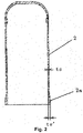
- a wall thickness of a welding portion 2a butt-welded with a valve base 1 of a rotor housing 2 is ts'
- a wall thickness of a coil mounting portion of the rotor housing 2 is ts, wherein ts' is greater than ts.
- the rotor housing 2 is a stamped workpiece formed by stamping a material of which a thickness is equal to the wall thickness of the welding portion 2a.
- the increase of the wall thickness of the welding portion 2a can ensure the melting range width and melting depth of a base material of a welding end face (a weld joint is formed between a lower end face of the welding portion 2a of the rotor housing 2 and an upper end face of the valve base 1), thereby ensuring welding strength to a certain extent.
- the housing structure still results in the phenomenon that fatigue damage is likely to occur at a weld joint under a long-time fatigue impact of a high-pressure environment.
- the existing housing structure also has problems as follows.
- a housing assembly of a valve is a housing assembly of an electronic expansion valve.
- the housing assembly comprises a valve base 10 and a housing 20 fixedly provided on the valve base 10.
- the housing 20 is a rotor housing.
- the valve base 10 has a first fitting end face facing the housing 20.
- the housing 20 has a second fitting end face matched with the first fitting end face of the valve base 10.
- the housing assembly of the present embodiment further comprises a sleeve 30 and a first reinforcement portion 41, wherein the sleeve 30 is provided on an outer side of the valve base 10 and the housing 20.
- the sleeve 30 shelters from the first fitting end face and the second fitting end face.
- the first reinforcement portion 41 is provided on an outer side wall of the sleeve 30, and the first reinforcement portion 41 is located above the first fitting end face.
- the sleeve 30 sleeves the valve base 10 and the housing 20, and the sleeve 30 shelters from the first fitting end face and the second fitting end face.
- a first reinforcement portion 41 is provided on the outer side wall of the sleeve 30. The first reinforcement portion 41 is located above the first fitted end face.
- a melting range width and a melting depth of a base material of a welding face can be ensured by utilizing an own wall thickness of the sleeve 30, so that welding strength can be ensured even if the wall thickness of a welding portion of the housing 20 is not increased, thereby avoiding a complex machining process of the housing 20 and a phenomenon of easy breakage.
- the first reinforcement portion 41 is provided on the outer side wall of the sleeve 30 and located above the first fitted end face, so that a pressure resistance reinforcement action can be exerted on the housing 20, i.e., the housing 20 can be effectively protected under a high-pressure impact, and a deformation of a welding part of the housing 20 can be reduced, thereby preventing fatigue damage at a weld joint, and increasing a reliability of the weld joint.
- the sleeve 30 sleeves the valve base 10 and the housing 20, the sleeve 30 shelters from the first fitting end face and the second fitting end face, and the laser welding is performed at a position A, corresponding to the first fitted end face and the second fitted end face, of the sleeve 30.
- the disposing position of the sleeve 30 is not limited to this.
- the sleeve 30 may also be only provided on the housing 20, and the housing 20 and the valve base 10 can be directly welded (i.e., welding faces are the first fitting end face and the second fitting end face), so that the housing 20 and the valve base 10 can be connected, the sleeve 30 can effectively protect the housing 20, and the deformation of a welding part of the housing 20 is reduced, thereby preventing fatigue damage at a weld joint, and increasing the reliability of the weld joint.
- the sleeve 30 and the housing 20 are in an interference fit.
- the first reinforcement portion 41 is of a sealed circular structure.
- the sleeve 30 and the housing 20 are set to be in interference fit, so that the sleeve 30 can tightly clamp the housing 20.
- the housing 20 can be further protected to prevent a welding part of the housing 20 from deforming under a high-pressure impact, thereby protecting a weld joint. Since the first reinforcement portion 41 is provided at a position corresponding to the housing 20, the interference fit between the sleeve 30 and the housing 20 can make the first reinforcement portion 41 and the housing 20 fitted more tightly, thereby preventing fatigue damage at a weld joint.
- the sleeve 30 has a first sleeve segment matched with the valve base 10 and a second sleeve segment matched with the housing 20.
- An inner diameter of the first sleeve segment is equal to an inner diameter of the second sleeve segment.
- the first reinforcement portion 41 is protruded out of the sleeve 30 along a radial direction of the housing 20, and a weld joint is formed among the first fitting end face, the second fitting end face and the position A of the sleeve 30.
- the sleeve 30 When the housing assembly is welded, the sleeve 30 is pressed against the valve base 10 and the housing 20, so that the sleeve 30 is in interference fit with the valve base 10 and the sleeve 30 is in interference fit with the housing 20. In this process, the position A of the sleeve 30 below the first reinforcement portion 41 is aligned with the first fitting end face and the second fitting end face, which are overlapped. Thereafter, laser welding is performed at the position A of the sleeve 30.
- the melting range width and melting depth of a base material of a welding face (the first fitted end face, the second fitted end face and an inner side face of the position A of the sleeve 30) can be ensured by utilizing the wall thickness of the position A of the sleeve 30.
- the protruded first reinforcement portion 41 is unlikely to deform due to a large thickness along the radial direction of the sleeve 30. Under a high-pressure impact, the protruded first reinforcement portion 41 can more effectively protect the housing 20, and the deformation of a welding part of the housing 20 is reduced, thereby preventing fatigue damage at a weld joint.
- the wall thickness of the sleeve 30 located at a welding position should be matched with a laser source (laser energy) for laser welding. If the wall thickness of the sleeve 30 located at the welding position is too large for the laser source, the welding effect will be influenced, and the first fitting end face and the second fitting end face cannot be even effectively welded together.
- the housing assembly further comprises a sleeve 30 and a reinforcement portion 40 provided on an outer side wall of the sleeve 30, wherein the sleeve 30 sleeves the valve base 10 and the housing 20.
- the sleeve 30 keeps out a first fitting end face and a second fitting end face.
- the reinforcement portion 40 comprises a first reinforcement portion 41 provided above the first fitting end face and a second reinforcement portion 42 provided below the second fitting end face.
- a first weld joint is formed between a first sleeve segment and a position B of the valve base 10, and a second weld joint is formed between a second sleeve segment and a position C of the housing 20.
- the first reinforcement portion 41 and the second reinforcement portion 42 are provided between the first weld joint and the second weld joint (i.e., provided between the position B and the position C).
- the sleeve 30 When the housing assembly is welded, the sleeve 30 is pressed against the valve base 10 and the housing 20, so that the sleeve 30 is in interference fit with the valve base 10 and the housing 20.
- the position B of the first sleeve segment above the first reinforcement portion 41 corresponds to the housing 20
- the position C of the second sleeve segment below the second reinforcement portion 42 corresponds to the valve base 10.
- the first reinforcement portion 41 and the second reinforcement portion 42 are close to the first fitting end face and the second fitting end face, which are overlapped.
- laser welding is performed at the position B and position C of the sleeve 30.
- the melting range width and melting depth of a base material of a welding face (an inner side face at the position B of the first sleeve segment, an outer side face of the housing 20, an inner side face at the position C of the second sleeve segment, and an outer side face of the valve base 10) can be ensured by utilizing the wall thickness of the position B of the first sleeve segment and the position C of the second sleeve segment.
- the first reinforcement portion 41 and the second reinforcement portion 42 can reinforce the first fitting end face and the second fitting end face, the housing 20 and the valve base 10 can be more effectively protected, and the deformation of a welding part of the housing 20 and a welding part of the valve base 10 is reduced, thereby preventing fatigue damage at a weld joint.
- the first reinforcement portion 41 and the second reinforcement portion 42 are connected together and form a whole structure.
- the first reinforcement portion 41 and the second reinforcement portion 42 shelter from the first fitting end face and the second fitting end face.
- the structure can enhance the reinforcement effects of the first reinforcement portion 41 and the second reinforcement portion 42, the structure is simple, and workability is achieved.
- the sleeve 30 has a first sleeve segment matched with the valve base 10 and a second sleeve segment matched with the housing 20.
- An inner diameter of the first sleeve segment is greater than an inner diameter of the second sleeve segment.
- a stepped face is formed between an inner side wall of the first sleeve segment and an inner side wall of the second sleeve segment. The stepped face is aligned with the first fitting end face.
- a weld joint is formed among the first fitting end face, the second fitting end face and the stepped face.
- the sleeve 30 When the housing assembly is welded, the sleeve 30 is pressed against the valve base 10 and the housing 20, so that the sleeve 30 is in interference fit with the valve base 10 and the housing 20. In this process, a position D of the sleeve 30 below the first reinforcement portion 41 can be directly aligned with the first fitting end face and the second fitting end face, which are overlapped, via the stepped face of the sleeve 30 without manual alignment or tool-based alignment. Thereafter, laser welding is performed at the position D of the sleeve 30.
- the melting range width and melting depth of a base material of a welding face (the first fitted end face, the second fitted end face and the stepped face of the sleeve 30) can be ensured by utilizing the wall thickness of the position D of the sleeve 30.
- the first reinforcement portion 41 can more effectively protect the housing 20, and the deformation of a welding part of the housing 20 is reduced, thereby preventing fatigue damage at a weld joint.
- the valve base 10 has a cylindrical structure extending toward the housing 20 and provided on the outer side of the housing 20, the cylindrical structure forming the sleeve 30.
- the structure of the housing assembly can be simplified, it is unnecessary to independently set a sleeve structure, and workability is achieved.
- a position, corresponding to a welding end face of the housing 20, on the outer side of the cylindrical structure (i.e., sleeve 30) of the valve base 10 is a position E.
- laser welding is performed at the position E of the cylindrical structure.
- the melting range width and melting depth of a base material of a welding face (the first fitted end face, the second fitted end face and an inner side face of the position E of the cylindrical structure) can be ensured by utilizing the wall thickness of the position E of the cylindrical structure of the valve base 10.
- the first reinforcement portion 41 at the upper part of the cylindrical structure can more effectively protect the housing 20, and the deformation of a welding part of the housing 20 is reduced, thereby preventing fatigue damage at a weld joint.
- the present application also provides a valve, comprising a housing assembly.
- the housing assembly is the housing assembly in the embodiment 1.
- the welding strength of the valve can be ensured, fatigue damage is unlikely to occur, and the service life is long. It is important to note that the valve is not limited to adopt the housing assembly in the embodiment 1. In other implementation manners not shown in the figures, the valve may also adopt the housing assembly in the embodiment 2 to the embodiment 4.
- the housing assembly in the present application can ensure welding strength even if the wall thickness of a welding portion of a housing is not increased, thereby avoiding a complex machining process of the housing and a phenomenon of easy breakage.
- a first reinforcement portion is provided on an outer side wall of a sleeve and located above a first fitted end face, so that a pressure resistance reinforcement action can be exerted on the housing. That is, the housing can be effectively protected under a high-pressure impact, and the deformation of a welding part of the housing can be reduced, thereby preventing fatigue damage at a weld joint, and increasing the reliability of the weld joint.
Landscapes
- Engineering & Computer Science (AREA)
- General Engineering & Computer Science (AREA)
- Mechanical Engineering (AREA)
- Physics & Mathematics (AREA)
- Thermal Sciences (AREA)
- Valve Housings (AREA)
- Fuel-Injection Apparatus (AREA)
Description
- The present invention relates to a technical field of housing assemblies, and more particularly to a housing assembly of a valve and a valve.
- At present, a housing of an electronic expansion valve consists of a valve base 1 and a
rotor housing 2, forming a welded connection there between. Therotor housing 2 has awelding portion 2a butt-welded with the valve base 1, a weld joint is formed between thewelding portion 2a and the valve base 1. In order to ensure normal working of a rotor of the electronic expansion valve, therotor housing 2 is usually made of a thin-walled piece (wall thickness is in a range of 0.2mm to 0.8mm). In a general application situation, welding strength between therotor housing 2 of a thin-walled structure and the valve base 1 can be ensured. However, in a supercritical high-pressure system such as CO2, therotor housing 2 of the thin-walled structure is likely to deform under a high-pressure impact, so that fatigue damage is likely to occur at a weld joint between therotor housing 2 and the valve base 1. -
DE102008040108A1 discloses a valve, in particular an injection or metering valves for fuel injection or exhaust systems of internal combustion engines, the valve includes a valve housing 11, a connecting cover 17, and a valve seat carrier 16, the valve housing 11 is made of a fiber composite material, the connecting cover 17 is engaged with the valve housing 11 through the annular shoulder, and the connecting cover 17 is fixedly connected with the valve housing 11. -
DE102013202776A1 discloses a valve for metering a fluid, and specifically discloses that a plastic flange 38 disposed at a joint of the sleeve 36 and the magnet member 27 by means of a package. -
US2015/129067 discloses an electronic expansion valve, a sleeve is fixed in a main valve cavity of the electronic expansion valve, and a valve core seat is axially movably provided in the sleeve, a circumferential side wall of the sleeve is provided with a sleeve flow passage, and a circumferential side wall of the valve core seat is provided with a valve core seat side hole; - A valve for flowing medium is disclosed in
DE102010030947A1 , which comprises a valve base and a housing fixedly provided on the valve base wherein the housing assembly further comprises: a sleeve, at least one portion of the sleeve is provided on an outer side of the housing in a sleeving manner; and a reinforcement portion, provided on an outer side wall of the sleeve, the reinforcement portion comprising a first reinforcement portion, the first reinforcement portion is protruded out of the sleeve along a radial direction of the housing; the sleeve is provided on an outer side of the valve base and the housing in a sleeving manner, and the sleeve is welded to the housing. - The present invention is mainly directed to a housing assembly of a valve and a valve, intended to solve the problem in the prior art in which fatigue damage is likely to occur at a weld joint of a housing assembly.
- The invention is defined by the appended claims.
- To this end, according to an aspect of the present invention, a housing assembly of a valve is provided. The housing assembly of a valve comprises a valve base and a housing fixedly provided on the valve base. The valve base has a first fitting end face facing the housing, and the housing has a second fitting end face matched with the first fitting end face of the valve base. The housing assembly further comprises: a sleeve, at least a portion of the sleeve is provided on an outer side of the housing in a sleeving manner; and a reinforcement portion, provided on an outer side wall of the sleeve, the reinforcement portion comprises a first reinforcement portion, the first reinforcement portion is located above the first fitting end face.
- According to the invention, the sleeve is provided on an outer side of the valve base and the housing in a sleeving manner, and the sleeve shelters from the first fitting end face and the second fitting end face.
- According to the invention, the sleeve and the housing are in interference fit.
- Further, the reinforcement portion is of a sealed circular structure.
- Further, the sleeve has a first sleeve segment matched with the valve base and a second sleeve segment matched with the housing, an inner diameter of the first sleeve segment is equal to an inner diameter of the second sleeve segment.
- According to the invention, the first reinforcement portion is protruded out of the sleeve along a radial direction of the housing, and a weld joint is formed among the first fitting end face, the second fitting end face and the sleeve.
- According to a second aspect of the invention, the reinforcement portion further comprises a second reinforcement portion, the second reinforcement portion is located below the second fitting end face, a first weld joint is formed between the first sleeve segment and the valve base, a second weld joint is formed between the second sleeve segment and the housing, and the first reinforcement portion and the second reinforcement portion are provided between the first weld joint and the second weld joint.
- Further, the first reinforcement portion and the second reinforcement portion are connected together and form a whole structure, and the first reinforcement portion and the second reinforcement portion shelter from the first fitting end face and the second fitting end face.
- Further, the sleeve has a first sleeve segment matched with the valve base and a second sleeve segment matched with the housing, an inner diameter of the first sleeve segment is greater than an inner diameter of the second sleeve segment, a stepped face is formed between an inner side wall of the first sleeve segment and an inner side wall of the second sleeve segment, the stepped face is matched with the first fitting end face, and a weld joint is formed among the first fitting end face, the second fitting end face and the stepped face.
- Further, the valve base has a cylindrical structure extending toward the housing and provided on the outer side of the housing, the cylindrical structure forming the sleeve.
- According to another aspect of the present disclosure, a valve is provided. The valve comprises a housing assembly, the housing assembly is the above-mentioned housing assembly.
- By applying the technical solution of the present invention, a sleeve at least sleeves a housing, and a first reinforcement portion is provided on an outer side wall of the sleeve, the first reinforcement portion is located above a first fitted end face. The first reinforcement portion can exert a pressure resistance reinforcement action on the housing, i.e., can effectively protect the housing under a high-pressure impact, and can reduce the deformation of a welding part of the housing, thereby preventing fatigue damage at a weld joint, and increasing the reliability of the weld joint.
- The drawings of the description, forming a part of the present application, are used to provide a further understanding for the present disclosure. The schematic embodiments and illustrations of the present disclosure are used to explain the present disclosure, and do not form improper limits to the present disclosure. In the drawings:
-
Fig. 1 shows a structure diagram of an electronic expansion valve in the prior art; -
Fig. 2 shows a structure diagram of a housing assembly of an electronic expansion valve inFig. 1 ; -
Fig. 3 shows a structure diagram of a housing assembly of a valve according to an embodiment 1 of the present invention; -
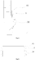
Fig. 4 shows a local enlarged view of a housing assembly inFig. 3 ; -
Fig. 5 shows a structure diagram of a sleeve of a housing assembly inFig. 3 ; -
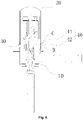
Fig. 6 shows a structure diagram of a housing assembly of a valve according to anembodiment 2 of the present invention; -
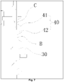
Fig. 7 shows a local enlarged view of a housing assembly inFig. 6 ; -
Fig. 8 shows a structure diagram of a sleeve of a housing assembly inFig. 6 ; -
Fig. 9 shows a structure diagram of a housing assembly of a valve according to an embodiment 3 of the present invention; -
Fig. 10 shows a local enlarged view of a housing assembly inFig. 9 ; -
Fig. 11 shows a structure diagram of a sleeve of a housing assembly inFig. 9 ; -
Fig. 12 shows a structure diagram of a housing assembly of a valve according to an embodiment 4 of the present disclosure; -
Fig. 13 shows a local enlarged view of a housing assembly inFig. 12 ; -
Fig. 14 shows a structure diagram of a valve base and a sleeve of a housing assembly inFig. 12 ; and -
Fig. 15 shows a structure diagram of a valve according to an embodiment of the present invention. - Herein, the drawings include the following drawing marks:
1, valve base; 2, rotor housing; 2a, welding portion; 10, valve base; 20, housing; 30, sleeve; 40, reinforcement portion; 41, first reinforcement portion; and 42, second reinforcement portion. - It is important to note that embodiments in the present application and characteristics in the embodiments may be combined mutually under the condition of no conflicts. The present disclosure will be illustrated herein below with reference to the drawings and in conjunction with the embodiments in detail.
- In the prior art, a special housing structure exists, and a phenomenon that fatigue damage is likely to occur at a weld joint can be alleviated to a certain extent. Specifically, as shown in
Fig. 1 andFig. 2 , a wall thickness of awelding portion 2a butt-welded with a valve base 1 of arotor housing 2 is ts', and a wall thickness of a coil mounting portion of therotor housing 2 is ts, wherein ts' is greater than ts. Therotor housing 2 is a stamped workpiece formed by stamping a material of which a thickness is equal to the wall thickness of thewelding portion 2a. The increase of the wall thickness of thewelding portion 2a can ensure the melting range width and melting depth of a base material of a welding end face (a weld joint is formed between a lower end face of thewelding portion 2a of therotor housing 2 and an upper end face of the valve base 1), thereby ensuring welding strength to a certain extent. However, the housing structure still results in the phenomenon that fatigue damage is likely to occur at a weld joint under a long-time fatigue impact of a high-pressure environment. - In addition, the existing housing structure also has problems as follows.
- 1. The
rotor housing 2 is formed by stamping a material of which the thickness is equal to the wall thickness of thewelding portion 2a, the wall thickness of thewelding portion 2a is inconsistent with the wall thickness of the coil mounting portion at an upper part of therotor housing 2, the stretching process is relative complex, and a mold is highly required. - 2. Stress is concentrated at a connection transition part between a wall of the
welding portion 2a and the coil mounting portion of therotor housing 2, thereby making it likely to cause breakage under a fatigue impact of a high-pressure environment. - As shown in
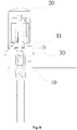
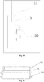
Fig. 3 to Fig. 5 , a housing assembly of a valve according to an embodiment 1 is a housing assembly of an electronic expansion valve. The housing assembly comprises avalve base 10 and ahousing 20 fixedly provided on thevalve base 10. Thehousing 20 is a rotor housing. Thevalve base 10 has a first fitting end face facing thehousing 20. Thehousing 20 has a second fitting end face matched with the first fitting end face of thevalve base 10. The housing assembly of the present embodiment further comprises asleeve 30 and afirst reinforcement portion 41, wherein thesleeve 30 is provided on an outer side of thevalve base 10 and thehousing 20. Thesleeve 30 shelters from the first fitting end face and the second fitting end face. Thefirst reinforcement portion 41 is provided on an outer side wall of thesleeve 30, and thefirst reinforcement portion 41 is located above the first fitting end face. - By application of the housing assembly in the present embodiment, the
sleeve 30 sleeves thevalve base 10 and thehousing 20, and thesleeve 30 shelters from the first fitting end face and the second fitting end face. Meanwhile, afirst reinforcement portion 41 is provided on the outer side wall of thesleeve 30. Thefirst reinforcement portion 41 is located above the first fitted end face. When the housing assembly is welded, a laser welding is performed at a position A, corresponding to the first fitted end face and the second fitted end face, of thesleeve 30. Thus, a melting range width and a melting depth of a base material of a welding face (the first fitted end face, the second fitted end face and an inner side face of the sleeve 30) can be ensured by utilizing an own wall thickness of thesleeve 30, so that welding strength can be ensured even if the wall thickness of a welding portion of thehousing 20 is not increased, thereby avoiding a complex machining process of thehousing 20 and a phenomenon of easy breakage. In addition, thefirst reinforcement portion 41 is provided on the outer side wall of thesleeve 30 and located above the first fitted end face, so that a pressure resistance reinforcement action can be exerted on thehousing 20, i.e., thehousing 20 can be effectively protected under a high-pressure impact, and a deformation of a welding part of thehousing 20 can be reduced, thereby preventing fatigue damage at a weld joint, and increasing a reliability of the weld joint. - It is important to note that in the present embodiment, the
sleeve 30 sleeves thevalve base 10 and thehousing 20, thesleeve 30 shelters from the first fitting end face and the second fitting end face, and the laser welding is performed at a position A, corresponding to the first fitted end face and the second fitted end face, of thesleeve 30. Certainly, the disposing position of thesleeve 30 is not limited to this. In other implementation manners not shown in the figures, thesleeve 30 may also be only provided on thehousing 20, and thehousing 20 and thevalve base 10 can be directly welded (i.e., welding faces are the first fitting end face and the second fitting end face), so that thehousing 20 and thevalve base 10 can be connected, thesleeve 30 can effectively protect thehousing 20, and the deformation of a welding part of thehousing 20 is reduced, thereby preventing fatigue damage at a weld joint, and increasing the reliability of the weld joint. - As shown in
Fig. 3 to Fig. 5 , in the housing assembly of the present embodiment, thesleeve 30 and thehousing 20 are in an interference fit. Thefirst reinforcement portion 41 is of a sealed circular structure. Thesleeve 30 and thehousing 20 are set to be in interference fit, so that thesleeve 30 can tightly clamp thehousing 20. Thus, thehousing 20 can be further protected to prevent a welding part of thehousing 20 from deforming under a high-pressure impact, thereby protecting a weld joint. Since thefirst reinforcement portion 41 is provided at a position corresponding to thehousing 20, the interference fit between thesleeve 30 and thehousing 20 can make thefirst reinforcement portion 41 and thehousing 20 fitted more tightly, thereby preventing fatigue damage at a weld joint. - As shown in
Fig. 3 to Fig. 5 , in the housing assembly of the present embodiment, thesleeve 30 has a first sleeve segment matched with thevalve base 10 and a second sleeve segment matched with thehousing 20. An inner diameter of the first sleeve segment is equal to an inner diameter of the second sleeve segment. Thefirst reinforcement portion 41 is protruded out of thesleeve 30 along a radial direction of thehousing 20, and a weld joint is formed among the first fitting end face, the second fitting end face and the position A of thesleeve 30. - When the housing assembly is welded, the
sleeve 30 is pressed against thevalve base 10 and thehousing 20, so that thesleeve 30 is in interference fit with thevalve base 10 and thesleeve 30 is in interference fit with thehousing 20. In this process, the position A of thesleeve 30 below thefirst reinforcement portion 41 is aligned with the first fitting end face and the second fitting end face, which are overlapped. Thereafter, laser welding is performed at the position A of thesleeve 30. Thus, the melting range width and melting depth of a base material of a welding face (the first fitted end face, the second fitted end face and an inner side face of the position A of the sleeve 30) can be ensured by utilizing the wall thickness of the position A of thesleeve 30. The protrudedfirst reinforcement portion 41 is unlikely to deform due to a large thickness along the radial direction of thesleeve 30. Under a high-pressure impact, the protrudedfirst reinforcement portion 41 can more effectively protect thehousing 20, and the deformation of a welding part of thehousing 20 is reduced, thereby preventing fatigue damage at a weld joint. - It is important to note that during laser welding, it is necessary to select a laser source for laser welding according to a specific weld joint requirement, and the wall thickness of the
sleeve 30 located at a welding position should be matched with a laser source (laser energy) for laser welding. If the wall thickness of thesleeve 30 located at the welding position is too large for the laser source, the welding effect will be influenced, and the first fitting end face and the second fitting end face cannot be even effectively welded together. - As shown in
Fig. 6 to Fig. 8 , main differences between the housing assembly of a valve in theembodiment 2 and the housing assembly of a valve in the embodiment 1 are that: the housing assembly further comprises asleeve 30 and areinforcement portion 40 provided on an outer side wall of thesleeve 30, wherein thesleeve 30 sleeves thevalve base 10 and thehousing 20. Thesleeve 30 keeps out a first fitting end face and a second fitting end face. Thereinforcement portion 40 comprises afirst reinforcement portion 41 provided above the first fitting end face and asecond reinforcement portion 42 provided below the second fitting end face. A first weld joint is formed between a first sleeve segment and a position B of thevalve base 10, and a second weld joint is formed between a second sleeve segment and a position C of thehousing 20. Thefirst reinforcement portion 41 and thesecond reinforcement portion 42 are provided between the first weld joint and the second weld joint (i.e., provided between the position B and the position C). - When the housing assembly is welded, the
sleeve 30 is pressed against thevalve base 10 and thehousing 20, so that thesleeve 30 is in interference fit with thevalve base 10 and thehousing 20. In this process, the position B of the first sleeve segment above thefirst reinforcement portion 41 corresponds to thehousing 20, and the position C of the second sleeve segment below thesecond reinforcement portion 42 corresponds to thevalve base 10. Meanwhile, thefirst reinforcement portion 41 and thesecond reinforcement portion 42 are close to the first fitting end face and the second fitting end face, which are overlapped. Thereafter, laser welding is performed at the position B and position C of thesleeve 30. Thus, the melting range width and melting depth of a base material of a welding face (an inner side face at the position B of the first sleeve segment, an outer side face of thehousing 20, an inner side face at the position C of the second sleeve segment, and an outer side face of the valve base 10) can be ensured by utilizing the wall thickness of the position B of the first sleeve segment and the position C of the second sleeve segment. Under a high-pressure impact, thefirst reinforcement portion 41 and thesecond reinforcement portion 42 can reinforce the first fitting end face and the second fitting end face, thehousing 20 and thevalve base 10 can be more effectively protected, and the deformation of a welding part of thehousing 20 and a welding part of thevalve base 10 is reduced, thereby preventing fatigue damage at a weld joint. - As shown in
Fig. 6 to Fig. 8 , in the housing assembly of the present embodiment, thefirst reinforcement portion 41 and thesecond reinforcement portion 42 are connected together and form a whole structure. Thefirst reinforcement portion 41 and thesecond reinforcement portion 42 shelter from the first fitting end face and the second fitting end face. The structure can enhance the reinforcement effects of thefirst reinforcement portion 41 and thesecond reinforcement portion 42, the structure is simple, and workability is achieved. - As shown in
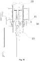
Fig. 9 to Fig. 11 , main differences between the housing assembly of a valve in the embodiment 3 and the housing assembly of a valve in the embodiment 1 are that: thesleeve 30 has a first sleeve segment matched with thevalve base 10 and a second sleeve segment matched with thehousing 20. An inner diameter of the first sleeve segment is greater than an inner diameter of the second sleeve segment. A stepped face is formed between an inner side wall of the first sleeve segment and an inner side wall of the second sleeve segment. The stepped face is aligned with the first fitting end face. A weld joint is formed among the first fitting end face, the second fitting end face and the stepped face. - When the housing assembly is welded, the
sleeve 30 is pressed against thevalve base 10 and thehousing 20, so that thesleeve 30 is in interference fit with thevalve base 10 and thehousing 20. In this process, a position D of thesleeve 30 below thefirst reinforcement portion 41 can be directly aligned with the first fitting end face and the second fitting end face, which are overlapped, via the stepped face of thesleeve 30 without manual alignment or tool-based alignment. Thereafter, laser welding is performed at the position D of thesleeve 30. Thus, the melting range width and melting depth of a base material of a welding face (the first fitted end face, the second fitted end face and the stepped face of the sleeve 30) can be ensured by utilizing the wall thickness of the position D of thesleeve 30. Under a high-pressure impact, thefirst reinforcement portion 41 can more effectively protect thehousing 20, and the deformation of a welding part of thehousing 20 is reduced, thereby preventing fatigue damage at a weld joint. - As shown in
Fig. 12 to Fig. 14 , main differences between the housing assembly of a valve in the embodiment 4 and the housing assembly of a valve in the embodiment 1 are that: thevalve base 10 has a cylindrical structure extending toward thehousing 20 and provided on the outer side of thehousing 20, the cylindrical structure forming thesleeve 30. Thus, the structure of the housing assembly can be simplified, it is unnecessary to independently set a sleeve structure, and workability is achieved. - When the housing assembly is welded, the
housing 20 is pressed against thevalve base 10. In this process, a position, corresponding to a welding end face of thehousing 20, on the outer side of the cylindrical structure (i.e., sleeve 30) of thevalve base 10 is a position E. Thereafter, laser welding is performed at the position E of the cylindrical structure. Thus, the melting range width and melting depth of a base material of a welding face (the first fitted end face, the second fitted end face and an inner side face of the position E of the cylindrical structure) can be ensured by utilizing the wall thickness of the position E of the cylindrical structure of thevalve base 10. Under a high-pressure impact, thefirst reinforcement portion 41 at the upper part of the cylindrical structure can more effectively protect thehousing 20, and the deformation of a welding part of thehousing 20 is reduced, thereby preventing fatigue damage at a weld joint. - As shown in
Fig. 15 , the present application also provides a valve, comprising a housing assembly. The housing assembly is the housing assembly in the embodiment 1. The welding strength of the valve can be ensured, fatigue damage is unlikely to occur, and the service life is long. It is important to note that the valve is not limited to adopt the housing assembly in the embodiment 1. In other implementation manners not shown in the figures, the valve may also adopt the housing assembly in theembodiment 2 to the embodiment 4. - From the above description, it can be seen that the embodiments of the present invention achieve the technical effects as follows.
- The housing assembly in the present application can ensure welding strength even if the wall thickness of a welding portion of a housing is not increased, thereby avoiding a complex machining process of the housing and a phenomenon of easy breakage. In addition, a first reinforcement portion is provided on an outer side wall of a sleeve and located above a first fitted end face, so that a pressure resistance reinforcement action can be exerted on the housing. That is, the housing can be effectively protected under a high-pressure impact, and the deformation of a welding part of the housing can be reduced, thereby preventing fatigue damage at a weld joint, and increasing the reliability of the weld joint.
- The above is only the preferable embodiments of the present disclosure, and not intended to limit the present disclosure. As will occur to a person skilled in the art, the present disclosure is susceptible to various modifications and changes within the scope of the attached claims.
Claims (7)
- A housing assembly of a valve, comprising:a valve base (10) and a housing (20) fixedly provided on the valve base (10), the valve base (10) has a first fitting end face facing the housing (20), and the housing (20) has a second fitting end face matched with the first fitting end face of the valve base (10),wherein the housing assembly further comprises:a sleeve (30), at least one portion of the sleeve (30) is provided on an outer side of the housing (20) in a sleeving manner; anda reinforcement portion (40), provided on an outer side wall of the sleeve (30), the reinforcement portion (40) comprising a first reinforcement portion (41), the first reinforcement portion (41) is located above the first fitting end face, the first reinforcement portion (41) is protruded out of the sleeve (30) along a radial direction of the housing (20); the sleeve (30) is provided on an outer side of the valve base (10) and the housing (20) in a sleeving manner, and the sleeve (30) shelters from the first fitting end face and the second fitting end face, the sleeve (30) and the housing (20) are in interference fit, and the sleeve (30) is welded to the housing (20), a weld joint is formed among the first fitting end face, the second fitting end face and the sleeve (30).
- The housing assembly as claimed in claim 1, wherein the reinforcement portion (40) is of a sealed circular structure.
- The housing assembly as claimed in claim 1, wherein the sleeve (30) has a first sleeve segment matched with the valve base (10) and a second sleeve segment matched with the housing (20), an inner diameter of the first sleeve segment is equal to an inner diameter of the second sleeve segment.
- The housing assembly as claimed in claim 1, wherein the sleeve (30) has a first sleeve segment matched with the valve base (10) and a second sleeve segment matched with the housing (20), an inner diameter of the first sleeve segment is greater than an inner diameter of the second sleeve segment, a stepped face is formed between an inner side wall of the first sleeve segment and an inner side wall of the second sleeve segment, the stepped face is matched with the first fitting end face, and a weld joint is formed among the first fitting end face, the second fitting end face and the stepped face.
- A housing assembly of a valve, comprising:a valve base (10) and a housing (20) fixedly provided on the valve base (10), the valve base (10) has a first fitting end face facing the housing (20), and the housing (20) has a second fitting end face matched with the first fitting end face of the valve base (10),wherein the housing assembly further comprises:a sleeve (30), at least one portion of the sleeve (30) is provided on an outer side of the housing (20) in a sleeving manner; anda reinforcement portion (40), provided on an outer side wall of the sleeve (30), the reinforcement portion (40) comprising a first reinforcement portion (41) and a second reinforcement portion (42), the first reinforcement portion (41) is located above the first fitting end face, the second reinforcement portion (42) is located below the second fitting end face, the first reinforcement portion (41) is protruded out of the sleeve (30) along a radial direction of the housing (20); the sleeve (30) is provided on an outer side of the valve base (10) and the housing (20) in a sleeving manner, and the sleeve (30) shelters from the first fitting end face and the second fitting end face, the sleeve (30) and the housing (20) are in interference fit, and the sleeve (30) is welded to the housing (20);the sleeve (30) has a first sleeve segment matched with the valve base (10) and a second sleeve segment matched with the housing (20),a first weld joint is formed between the first sleeve segment and the valve base (10), a second weld joint is formed between the second sleeve segment and the housing (20), and the first reinforcement portion (41) and the second reinforcement portion (42) are provided between the first weld joint and the second weld joint.
- The housing assembly as claimed in claim 5, wherein the first reinforcement portion (41) and the second reinforcement portion (42) are connected together and form a whole structure, and the first reinforcement portion (41) and the second reinforcement portion (42) shelter from the first fitting end face and the second fitting end face.
- A valve, comprising a housing assembly, wherein the housing assembly is the housing assembly as claimed in any one of claims 1 to 6.
Applications Claiming Priority (2)
| Application Number | Priority Date | Filing Date | Title |
|---|---|---|---|
| CN201510486372.4A CN106439150A (en) | 2015-08-10 | 2015-08-10 | Valve shell assembly and valve |
| PCT/CN2016/093990 WO2017025009A1 (en) | 2015-08-10 | 2016-08-08 | Housing assembly of valve and valve |
Publications (3)
| Publication Number | Publication Date |
|---|---|
| EP3336399A1 EP3336399A1 (en) | 2018-06-20 |
| EP3336399A4 EP3336399A4 (en) | 2019-04-24 |
| EP3336399B1 true EP3336399B1 (en) | 2022-09-28 |
Family
ID=57983105
Family Applications (1)
| Application Number | Title | Priority Date | Filing Date |
|---|---|---|---|
| EP16834633.6A Active EP3336399B1 (en) | 2015-08-10 | 2016-08-08 | Housing assembly of valve and valve |
Country Status (5)
| Country | Link |
|---|---|
| EP (1) | EP3336399B1 (en) |
| JP (1) | JP6650036B2 (en) |
| KR (1) | KR102082231B1 (en) |
| CN (1) | CN106439150A (en) |
| WO (1) | WO2017025009A1 (en) |
Families Citing this family (2)
| Publication number | Priority date | Publication date | Assignee | Title |
|---|---|---|---|---|
| CN209943646U (en) * | 2019-04-15 | 2020-01-14 | 浙江盾安禾田金属有限公司 | Expansion valve coil assembly |
| CN114662225B (en) * | 2022-02-15 | 2023-05-26 | 东方电气集团东方电机有限公司 | Finite element analysis method for upper guide sliding rotor system |
Citations (1)
| Publication number | Priority date | Publication date | Assignee | Title |
|---|---|---|---|---|
| DE102010030947A1 (en) * | 2010-07-05 | 2012-01-05 | Robert Bosch Gmbh | Valve for flowing medium, particularly metering valve for metering freezing liquid, comprises valve housing, which has valve seat support fixed in valve housing, and valve seat body, which closes distant ends of pipe sections |
Family Cites Families (26)
| Publication number | Priority date | Publication date | Assignee | Title |
|---|---|---|---|---|
| JPS5659075A (en) * | 1979-10-18 | 1981-05-22 | Fuji Koki Seisakusho:Kk | Manufacture of solenoid valve |
| CA1134244A (en) * | 1979-12-17 | 1982-10-26 | Dow V. Morris | High pressure fluid end block and valve assembly |
| JPS6117580U (en) * | 1984-07-06 | 1986-02-01 | 松下冷機株式会社 | solenoid valve |
| DE3427526A1 (en) * | 1984-07-26 | 1986-02-06 | Robert Bosch Gmbh, 7000 Stuttgart | ELECTROMAGNETICALLY ACTUABLE VALVE |
| JPS62108741U (en) * | 1985-12-25 | 1987-07-11 | ||
| US5125690A (en) * | 1989-12-15 | 1992-06-30 | Metcal, Inc. | Pipe joining system and method |
| JPH10281324A (en) * | 1997-04-11 | 1998-10-23 | Fuji Koki Corp | Electrically-operated valve |
| JP2005003029A (en) * | 2003-06-10 | 2005-01-06 | Hiraoka Kinzoku Kogyo Kk | Pipe joint structure |
| US7192003B2 (en) * | 2004-09-21 | 2007-03-20 | Aseptic Controls Investment Co. | Aseptic sampling valve |
| SE528189C2 (en) * | 2004-12-21 | 2006-09-19 | Sandvik Intellectual Property | Method and pipe joint for joining components comprising or made of a material which is difficult to weld |
| JP4639102B2 (en) * | 2005-03-18 | 2011-02-23 | 株式会社不二工機 | Motorized valve |
| DE102008040108B9 (en) * | 2008-07-03 | 2023-09-07 | Robert Bosch Gmbh | Valve, in particular injection or dosing valve in fuel injection or exhaust systems of internal combustion engines |
| DE102010041989B4 (en) * | 2010-10-05 | 2025-05-22 | Robert Bosch Gmbh | Valve for a flowing medium |
| CN102767636A (en) * | 2011-05-04 | 2012-11-07 | 浙江三花股份有限公司 | Electric valve |
| CN102853142B (en) * | 2011-06-30 | 2015-07-01 | 浙江三花股份有限公司 | Electric valve |
| CN202338709U (en) * | 2011-12-05 | 2012-07-18 | 武汉市建筑设计院 | Anti-corrosion leakage prevention metal pipe joint |
| US9689595B2 (en) * | 2012-05-18 | 2017-06-27 | Zhejiang Sanhua Intelligent Controls Co., Ltd. | Electronic expansion valve |
| CN103453699B (en) * | 2012-05-29 | 2016-08-10 | 浙江三花股份有限公司 | A kind of electric expansion valve |
| CN202691389U (en) * | 2012-06-15 | 2013-01-23 | 邹佰营 | Rapid connector operated by utilizing pressure difference among connectors under high-pressure state |
| CN103575000B (en) * | 2012-08-10 | 2017-03-01 | 浙江三花智能控制股份有限公司 | A kind of electric expansion valve |
| JP2014047862A (en) * | 2012-08-31 | 2014-03-17 | Hitachi Automotive Systems Ltd | Electromagnetic valve |
| DE102013202776A1 (en) * | 2013-02-20 | 2014-08-21 | Robert Bosch Gmbh | Valve for metering of fluid, has sleeve that is pushed on tube portion, and has fluid-tight joint that is produced by material closure to valve housing |
| JP6277050B2 (en) * | 2013-05-20 | 2018-02-07 | 株式会社不二工機 | Electrically driven valve |
| CN103615582B (en) * | 2013-12-04 | 2017-01-04 | 沈阳航天新光集团有限公司 | Reducing valve |
| CN203963346U (en) * | 2014-05-14 | 2014-11-26 | 江西艾克实业有限公司 | A kind of portable type Quick push/pull joint |
| CN203963306U (en) * | 2014-05-14 | 2014-11-26 | 江西艾克实业有限公司 | A kind of rapid pipe joint that is threaded that adopts axial seal mode |
-
2015
- 2015-08-10 CN CN201510486372.4A patent/CN106439150A/en active Pending
-
2016
- 2016-08-08 KR KR1020187006841A patent/KR102082231B1/en not_active Expired - Fee Related
- 2016-08-08 WO PCT/CN2016/093990 patent/WO2017025009A1/en not_active Ceased
- 2016-08-08 EP EP16834633.6A patent/EP3336399B1/en active Active
- 2016-08-08 JP JP2018526982A patent/JP6650036B2/en not_active Expired - Fee Related
Patent Citations (1)
| Publication number | Priority date | Publication date | Assignee | Title |
|---|---|---|---|---|
| DE102010030947A1 (en) * | 2010-07-05 | 2012-01-05 | Robert Bosch Gmbh | Valve for flowing medium, particularly metering valve for metering freezing liquid, comprises valve housing, which has valve seat support fixed in valve housing, and valve seat body, which closes distant ends of pipe sections |
Also Published As
| Publication number | Publication date |
|---|---|
| JP6650036B2 (en) | 2020-02-19 |
| JP2018523078A (en) | 2018-08-16 |
| KR102082231B1 (en) | 2020-02-27 |
| KR20180051528A (en) | 2018-05-16 |
| CN106439150A (en) | 2017-02-22 |
| EP3336399A4 (en) | 2019-04-24 |
| WO2017025009A1 (en) | 2017-02-16 |
| EP3336399A1 (en) | 2018-06-20 |
Similar Documents
| Publication | Publication Date | Title |
|---|---|---|
| US5236174A (en) | Electromagnetically operable valve | |
| US6789779B2 (en) | Magnet valve, in particular for a traction-controlled hydraulic vehicle brake system | |
| JP6253798B2 (en) | Fuel rail | |
| US9890752B2 (en) | Muffler | |
| CN102759233B (en) | Electronic expansion valve | |
| JP4021838B2 (en) | Fuel injection device | |
| US20090243285A1 (en) | Device for securing high-pressure lines to a high-pressure reservoir | |
| US6441335B1 (en) | Process for beam-welding two members different in hardness | |
| KR20150118918A (en) | High pressure fuel pump having a exhaust valve with a valve body and a valve ball | |
| EP3336399A1 (en) | Housing assembly of valve and valve | |
| JP2007016774A (en) | Fuel injection valve and manufacturing method thereof | |
| US6874710B2 (en) | Fuel injection valve | |
| US10107243B2 (en) | Fuel injection valve | |
| KR20100114902A (en) | Method for aligning an elongated component | |
| US10919109B2 (en) | Method for producing a piston for an internal combustion engine consisting of a piston upper part and of a piston lower part | |
| KR20160069534A (en) | Fuel rail having high intensity assembling structure | |
| JP6033306B2 (en) | Valve for metering a flowing medium | |
| JPH0141828B2 (en) | ||
| WO2018159327A1 (en) | Fuel injection valve and method for manufacturing fuel injection valve | |
| JP7692991B2 (en) | One-way valve | |
| US20120280158A1 (en) | Magnetic Valve having a Core Sleeve and Method for Welding Thereof | |
| JP2014173515A (en) | Fuel injection valve | |
| JPH10115267A (en) | Fuel injection valve | |
| JP2008303966A (en) | O-ring assembly structure, high-pressure tank, and high-pressure tank manufacturing method | |
| EP3194756B1 (en) | Fuel injector |
Legal Events
| Date | Code | Title | Description |
|---|---|---|---|
| STAA | Information on the status of an ep patent application or granted ep patent |
Free format text: STATUS: THE INTERNATIONAL PUBLICATION HAS BEEN MADE |
|
| PUAI | Public reference made under article 153(3) epc to a published international application that has entered the european phase |
Free format text: ORIGINAL CODE: 0009012 |
|
| STAA | Information on the status of an ep patent application or granted ep patent |
Free format text: STATUS: REQUEST FOR EXAMINATION WAS MADE |
|
| 17P | Request for examination filed |
Effective date: 20180219 |
|
| AK | Designated contracting states |
Kind code of ref document: A1 Designated state(s): AL AT BE BG CH CY CZ DE DK EE ES FI FR GB GR HR HU IE IS IT LI LT LU LV MC MK MT NL NO PL PT RO RS SE SI SK SM TR |
|
| AX | Request for extension of the european patent |
Extension state: BA ME |
|
| DAV | Request for validation of the european patent (deleted) | ||
| DAX | Request for extension of the european patent (deleted) | ||
| A4 | Supplementary search report drawn up and despatched |
Effective date: 20190321 |
|
| RIC1 | Information provided on ipc code assigned before grant |
Ipc: F16K 27/00 20060101ALI20190315BHEP Ipc: F25B 41/06 20060101ALI20190315BHEP Ipc: F16K 25/00 20060101AFI20190315BHEP |
|
| STAA | Information on the status of an ep patent application or granted ep patent |
Free format text: STATUS: EXAMINATION IS IN PROGRESS |
|
| 17Q | First examination report despatched |
Effective date: 20210930 |
|
| GRAP | Despatch of communication of intention to grant a patent |
Free format text: ORIGINAL CODE: EPIDOSNIGR1 |
|
| STAA | Information on the status of an ep patent application or granted ep patent |
Free format text: STATUS: GRANT OF PATENT IS INTENDED |
|
| RIC1 | Information provided on ipc code assigned before grant |
Ipc: F25B 41/31 20210101ALI20220502BHEP Ipc: F25B 41/34 20210101ALI20220502BHEP Ipc: F16K 27/00 20060101ALI20220502BHEP Ipc: F16K 25/00 20060101AFI20220502BHEP |
|
| INTG | Intention to grant announced |
Effective date: 20220518 |
|
| GRAS | Grant fee paid |
Free format text: ORIGINAL CODE: EPIDOSNIGR3 |
|
| GRAA | (expected) grant |
Free format text: ORIGINAL CODE: 0009210 |
|
| STAA | Information on the status of an ep patent application or granted ep patent |
Free format text: STATUS: THE PATENT HAS BEEN GRANTED |
|
| AK | Designated contracting states |
Kind code of ref document: B1 Designated state(s): AL AT BE BG CH CY CZ DE DK EE ES FI FR GB GR HR HU IE IS IT LI LT LU LV MC MK MT NL NO PL PT RO RS SE SI SK SM TR |
|
| REG | Reference to a national code |
Ref country code: GB Ref legal event code: FG4D |
|
| REG | Reference to a national code |
Ref country code: CH Ref legal event code: EP |
|
| REG | Reference to a national code |
Ref country code: AT Ref legal event code: REF Ref document number: 1521431 Country of ref document: AT Kind code of ref document: T Effective date: 20221015 |
|
| REG | Reference to a national code |
Ref country code: DE Ref legal event code: R096 Ref document number: 602016075321 Country of ref document: DE |
|
| REG | Reference to a national code |
Ref country code: IE Ref legal event code: FG4D |
|
| REG | Reference to a national code |
Ref country code: LT Ref legal event code: MG9D |
|
| PG25 | Lapsed in a contracting state [announced via postgrant information from national office to epo] |
Ref country code: SE Free format text: LAPSE BECAUSE OF FAILURE TO SUBMIT A TRANSLATION OF THE DESCRIPTION OR TO PAY THE FEE WITHIN THE PRESCRIBED TIME-LIMIT Effective date: 20220928 Ref country code: RS Free format text: LAPSE BECAUSE OF FAILURE TO SUBMIT A TRANSLATION OF THE DESCRIPTION OR TO PAY THE FEE WITHIN THE PRESCRIBED TIME-LIMIT Effective date: 20220928 Ref country code: NO Free format text: LAPSE BECAUSE OF FAILURE TO SUBMIT A TRANSLATION OF THE DESCRIPTION OR TO PAY THE FEE WITHIN THE PRESCRIBED TIME-LIMIT Effective date: 20221228 Ref country code: LV Free format text: LAPSE BECAUSE OF FAILURE TO SUBMIT A TRANSLATION OF THE DESCRIPTION OR TO PAY THE FEE WITHIN THE PRESCRIBED TIME-LIMIT Effective date: 20220928 Ref country code: LT Free format text: LAPSE BECAUSE OF FAILURE TO SUBMIT A TRANSLATION OF THE DESCRIPTION OR TO PAY THE FEE WITHIN THE PRESCRIBED TIME-LIMIT Effective date: 20220928 Ref country code: FI Free format text: LAPSE BECAUSE OF FAILURE TO SUBMIT A TRANSLATION OF THE DESCRIPTION OR TO PAY THE FEE WITHIN THE PRESCRIBED TIME-LIMIT Effective date: 20220928 |
|
| REG | Reference to a national code |
Ref country code: NL Ref legal event code: MP Effective date: 20220928 |
|
| REG | Reference to a national code |
Ref country code: AT Ref legal event code: MK05 Ref document number: 1521431 Country of ref document: AT Kind code of ref document: T Effective date: 20220928 |
|
| PG25 | Lapsed in a contracting state [announced via postgrant information from national office to epo] |
Ref country code: HR Free format text: LAPSE BECAUSE OF FAILURE TO SUBMIT A TRANSLATION OF THE DESCRIPTION OR TO PAY THE FEE WITHIN THE PRESCRIBED TIME-LIMIT Effective date: 20220928 Ref country code: GR Free format text: LAPSE BECAUSE OF FAILURE TO SUBMIT A TRANSLATION OF THE DESCRIPTION OR TO PAY THE FEE WITHIN THE PRESCRIBED TIME-LIMIT Effective date: 20221229 |
|
| PG25 | Lapsed in a contracting state [announced via postgrant information from national office to epo] |
Ref country code: SM Free format text: LAPSE BECAUSE OF FAILURE TO SUBMIT A TRANSLATION OF THE DESCRIPTION OR TO PAY THE FEE WITHIN THE PRESCRIBED TIME-LIMIT Effective date: 20220928 Ref country code: RO Free format text: LAPSE BECAUSE OF FAILURE TO SUBMIT A TRANSLATION OF THE DESCRIPTION OR TO PAY THE FEE WITHIN THE PRESCRIBED TIME-LIMIT Effective date: 20220928 Ref country code: PT Free format text: LAPSE BECAUSE OF FAILURE TO SUBMIT A TRANSLATION OF THE DESCRIPTION OR TO PAY THE FEE WITHIN THE PRESCRIBED TIME-LIMIT Effective date: 20230130 Ref country code: ES Free format text: LAPSE BECAUSE OF FAILURE TO SUBMIT A TRANSLATION OF THE DESCRIPTION OR TO PAY THE FEE WITHIN THE PRESCRIBED TIME-LIMIT Effective date: 20220928 Ref country code: CZ Free format text: LAPSE BECAUSE OF FAILURE TO SUBMIT A TRANSLATION OF THE DESCRIPTION OR TO PAY THE FEE WITHIN THE PRESCRIBED TIME-LIMIT Effective date: 20220928 Ref country code: AT Free format text: LAPSE BECAUSE OF FAILURE TO SUBMIT A TRANSLATION OF THE DESCRIPTION OR TO PAY THE FEE WITHIN THE PRESCRIBED TIME-LIMIT Effective date: 20220928 |
|
| PG25 | Lapsed in a contracting state [announced via postgrant information from national office to epo] |
Ref country code: SK Free format text: LAPSE BECAUSE OF FAILURE TO SUBMIT A TRANSLATION OF THE DESCRIPTION OR TO PAY THE FEE WITHIN THE PRESCRIBED TIME-LIMIT Effective date: 20220928 Ref country code: PL Free format text: LAPSE BECAUSE OF FAILURE TO SUBMIT A TRANSLATION OF THE DESCRIPTION OR TO PAY THE FEE WITHIN THE PRESCRIBED TIME-LIMIT Effective date: 20220928 Ref country code: IS Free format text: LAPSE BECAUSE OF FAILURE TO SUBMIT A TRANSLATION OF THE DESCRIPTION OR TO PAY THE FEE WITHIN THE PRESCRIBED TIME-LIMIT Effective date: 20230128 Ref country code: EE Free format text: LAPSE BECAUSE OF FAILURE TO SUBMIT A TRANSLATION OF THE DESCRIPTION OR TO PAY THE FEE WITHIN THE PRESCRIBED TIME-LIMIT Effective date: 20220928 |
|
| REG | Reference to a national code |
Ref country code: DE Ref legal event code: R097 Ref document number: 602016075321 Country of ref document: DE |
|
| PG25 | Lapsed in a contracting state [announced via postgrant information from national office to epo] |
Ref country code: NL Free format text: LAPSE BECAUSE OF FAILURE TO SUBMIT A TRANSLATION OF THE DESCRIPTION OR TO PAY THE FEE WITHIN THE PRESCRIBED TIME-LIMIT Effective date: 20220928 Ref country code: AL Free format text: LAPSE BECAUSE OF FAILURE TO SUBMIT A TRANSLATION OF THE DESCRIPTION OR TO PAY THE FEE WITHIN THE PRESCRIBED TIME-LIMIT Effective date: 20220928 |
|
| PG25 | Lapsed in a contracting state [announced via postgrant information from national office to epo] |
Ref country code: DK Free format text: LAPSE BECAUSE OF FAILURE TO SUBMIT A TRANSLATION OF THE DESCRIPTION OR TO PAY THE FEE WITHIN THE PRESCRIBED TIME-LIMIT Effective date: 20220928 |
|
| PLBE | No opposition filed within time limit |
Free format text: ORIGINAL CODE: 0009261 |
|
| STAA | Information on the status of an ep patent application or granted ep patent |
Free format text: STATUS: NO OPPOSITION FILED WITHIN TIME LIMIT |
|
| 26N | No opposition filed |
Effective date: 20230629 |
|
| PG25 | Lapsed in a contracting state [announced via postgrant information from national office to epo] |
Ref country code: SI Free format text: LAPSE BECAUSE OF FAILURE TO SUBMIT A TRANSLATION OF THE DESCRIPTION OR TO PAY THE FEE WITHIN THE PRESCRIBED TIME-LIMIT Effective date: 20220928 |
|
| PG25 | Lapsed in a contracting state [announced via postgrant information from national office to epo] |
Ref country code: MC Free format text: LAPSE BECAUSE OF FAILURE TO SUBMIT A TRANSLATION OF THE DESCRIPTION OR TO PAY THE FEE WITHIN THE PRESCRIBED TIME-LIMIT Effective date: 20220928 |
|
| REG | Reference to a national code |
Ref country code: CH Ref legal event code: PL |
|
| PG25 | Lapsed in a contracting state [announced via postgrant information from national office to epo] |
Ref country code: MC Free format text: LAPSE BECAUSE OF FAILURE TO SUBMIT A TRANSLATION OF THE DESCRIPTION OR TO PAY THE FEE WITHIN THE PRESCRIBED TIME-LIMIT Effective date: 20220928 |
|
| PG25 | Lapsed in a contracting state [announced via postgrant information from national office to epo] |
Ref country code: LU Free format text: LAPSE BECAUSE OF NON-PAYMENT OF DUE FEES Effective date: 20230808 |
|
| GBPC | Gb: european patent ceased through non-payment of renewal fee |
Effective date: 20230808 |
|
| PG25 | Lapsed in a contracting state [announced via postgrant information from national office to epo] |
Ref country code: LU Free format text: LAPSE BECAUSE OF NON-PAYMENT OF DUE FEES Effective date: 20230808 Ref country code: CH Free format text: LAPSE BECAUSE OF NON-PAYMENT OF DUE FEES Effective date: 20230831 |
|
| REG | Reference to a national code |
Ref country code: BE Ref legal event code: MM Effective date: 20230831 |
|
| REG | Reference to a national code |
Ref country code: IE Ref legal event code: MM4A |
|
| PG25 | Lapsed in a contracting state [announced via postgrant information from national office to epo] |
Ref country code: IT Free format text: LAPSE BECAUSE OF FAILURE TO SUBMIT A TRANSLATION OF THE DESCRIPTION OR TO PAY THE FEE WITHIN THE PRESCRIBED TIME-LIMIT Effective date: 20220928 |
|
| PG25 | Lapsed in a contracting state [announced via postgrant information from national office to epo] |
Ref country code: IE Free format text: LAPSE BECAUSE OF NON-PAYMENT OF DUE FEES Effective date: 20230808 |
|
| PG25 | Lapsed in a contracting state [announced via postgrant information from national office to epo] |
Ref country code: GB Free format text: LAPSE BECAUSE OF NON-PAYMENT OF DUE FEES Effective date: 20230808 |
|
| PG25 | Lapsed in a contracting state [announced via postgrant information from national office to epo] |
Ref country code: IE Free format text: LAPSE BECAUSE OF NON-PAYMENT OF DUE FEES Effective date: 20230808 Ref country code: GB Free format text: LAPSE BECAUSE OF NON-PAYMENT OF DUE FEES Effective date: 20230808 |
|
| PG25 | Lapsed in a contracting state [announced via postgrant information from national office to epo] |
Ref country code: BE Free format text: LAPSE BECAUSE OF NON-PAYMENT OF DUE FEES Effective date: 20230831 |
|
| PG25 | Lapsed in a contracting state [announced via postgrant information from national office to epo] |
Ref country code: BG Free format text: LAPSE BECAUSE OF FAILURE TO SUBMIT A TRANSLATION OF THE DESCRIPTION OR TO PAY THE FEE WITHIN THE PRESCRIBED TIME-LIMIT Effective date: 20220928 |
|
| PG25 | Lapsed in a contracting state [announced via postgrant information from national office to epo] |
Ref country code: BG Free format text: LAPSE BECAUSE OF FAILURE TO SUBMIT A TRANSLATION OF THE DESCRIPTION OR TO PAY THE FEE WITHIN THE PRESCRIBED TIME-LIMIT Effective date: 20220928 |
|
| PG25 | Lapsed in a contracting state [announced via postgrant information from national office to epo] |
Ref country code: CY Free format text: LAPSE BECAUSE OF FAILURE TO SUBMIT A TRANSLATION OF THE DESCRIPTION OR TO PAY THE FEE WITHIN THE PRESCRIBED TIME-LIMIT; INVALID AB INITIO Effective date: 20160808 |
|
| PG25 | Lapsed in a contracting state [announced via postgrant information from national office to epo] |
Ref country code: HU Free format text: LAPSE BECAUSE OF FAILURE TO SUBMIT A TRANSLATION OF THE DESCRIPTION OR TO PAY THE FEE WITHIN THE PRESCRIBED TIME-LIMIT; INVALID AB INITIO Effective date: 20160808 |
|
| PGFP | Annual fee paid to national office [announced via postgrant information from national office to epo] |
Ref country code: DE Payment date: 20250812 Year of fee payment: 10 |
|
| PGFP | Annual fee paid to national office [announced via postgrant information from national office to epo] |
Ref country code: FR Payment date: 20250828 Year of fee payment: 10 |
|
| PG25 | Lapsed in a contracting state [announced via postgrant information from national office to epo] |
Ref country code: TR Free format text: LAPSE BECAUSE OF FAILURE TO SUBMIT A TRANSLATION OF THE DESCRIPTION OR TO PAY THE FEE WITHIN THE PRESCRIBED TIME-LIMIT Effective date: 20220928 |