EP3336232A1 - Drive apparatus for sewing machine - Google Patents
Drive apparatus for sewing machine Download PDFInfo
- Publication number
- EP3336232A1 EP3336232A1 EP17191427.8A EP17191427A EP3336232A1 EP 3336232 A1 EP3336232 A1 EP 3336232A1 EP 17191427 A EP17191427 A EP 17191427A EP 3336232 A1 EP3336232 A1 EP 3336232A1
- Authority
- EP
- European Patent Office
- Prior art keywords
- rotation speed
- motor
- drive circuit
- sewing
- switching element
- Prior art date
- Legal status (The legal status is an assumption and is not a legal conclusion. Google has not performed a legal analysis and makes no representation as to the accuracy of the status listed.)
- Withdrawn
Links
- 238000009958 sewing Methods 0.000 title claims abstract description 157
- 230000002159 abnormal effect Effects 0.000 claims description 18
- 230000005856 abnormality Effects 0.000 description 7
- 238000010586 diagram Methods 0.000 description 6
- 230000007246 mechanism Effects 0.000 description 6
- 238000000034 method Methods 0.000 description 6
- 230000008569 process Effects 0.000 description 6
- 230000008859 change Effects 0.000 description 4
- 239000004065 semiconductor Substances 0.000 description 4
- 230000005540 biological transmission Effects 0.000 description 3
- 230000000903 blocking effect Effects 0.000 description 1
- 239000004744 fabric Substances 0.000 description 1
- 230000020169 heat generation Effects 0.000 description 1
- 238000004519 manufacturing process Methods 0.000 description 1
- 238000012986 modification Methods 0.000 description 1
- 230000004048 modification Effects 0.000 description 1
- 230000004044 response Effects 0.000 description 1
Images



Classifications
-
- D—TEXTILES; PAPER
- D05—SEWING; EMBROIDERING; TUFTING
- D05B—SEWING
- D05B69/00—Driving-gear; Control devices
- D05B69/14—Devices for changing speed or for reversing direction of rotation
- D05B69/18—Devices for changing speed or for reversing direction of rotation electric, e.g. foot pedals
-
- D—TEXTILES; PAPER
- D05—SEWING; EMBROIDERING; TUFTING
- D05B—SEWING
- D05B69/00—Driving-gear; Control devices
-
- D—TEXTILES; PAPER
- D05—SEWING; EMBROIDERING; TUFTING
- D05B—SEWING
- D05B69/00—Driving-gear; Control devices
- D05B69/36—Devices for stopping drive when abnormal conditions occur, e.g. thread breakage
Definitions
- This disclosure relates to a drive apparatus for sewing machine, more specifically relates to a drive apparatus for a sewing machine including a motor, a first drive circuit, a second drive circuit, a rotation measuring unit, and a controller.
- shutoff circuit which shuts off the drive circuit in a case where the switching element is short-circuited has been proposed (for example, refer to JP 2006-34674A ).
- the shutoff circuit includes a thermal fuse connected to the drive circuit of the sewing machine in series, and an electric resistor which is adjacent to the thermal fuse and is connected to the drive start switch in parallel.
- the electric resistor of the shutoff circuit is connected to the drive start switch in parallel, and thus the shutoff circuit can only detect the short circuit of the switching element when a foot controller is not operated. For this reason, when the user operates the foot controller, even when the switching element is short-circuited, it is not possible to prevent the abnormal high speed rotation of the sewing machine motor.
- the drive start switch is turned off, a minute current flows into the electric resistor connected in parallel with the drive start switch, and thus energy efficiency is deteriorated.
- a drive apparatus for a sewing machine adopts configurations described below.
- a drive apparatus for a sewing machine includes a motor that drives a sewing needle; a first drive circuit that includes a first switching element which is connected to the motor in series when viewed from a power supply; a second drive circuit that includes a second switching element which is connected to the motor and the first switching element in series when viewed from the power supply; a rotation speed measuring unit that measures a rotation speed of the motor; and a controller that performs a sewing control when a sewing motion is commanded, in which the second drive circuit is controlled so as to turn on the second switching element, and the first drive circuit is controlled so as to drive the motor at a target rotation speed by switching the first switching element, in a predetermined period during which the sewing control is not executed, controls the first drive circuit and the second drive circuit such that one of the switching elements of the first switching element and the second switching element is turned on and the other switching element is turned off, and determines a first failure determination that determines a short circuit failure of the first drive circuit or the second drive circuit based on whether or not the
- the drive apparatus for a sewing machine is provided with the motor, the first drive circuit that includes the first switching element, the second drive circuit that includes the second switching element, the rotation speed measuring unit, and the controller.
- the controller performs a sewing control in which the second drive circuit is controlled so as to turn on the second switching element and the first drive circuit is controlled so as to drive the motor at a target rotation speed by switching the first switching element.
- the first switching element and the second switching element are connected to the power supply and the motor in series. For this reason, even if one switching element is short-circuited, it is possible to prevent the motor from being driven at an abnormal speed by turning off the other switching element.
- the controller controls the first drive circuit and the second drive circuit such that one of the switching elements of the first switching element and the second switching element is turned on and the other switching element is turned off, and determines a short circuit failure of the first drive circuit or the second drive circuit based on whether or not the rotation of the motor is detected by the rotation speed measuring unit. With this, it is possible to appropriately determine the short circuit failure of the first drive circuit or the second drive circuit by using the rotation speed measuring unit.
- the first failure determination may be performed in the predetermined period during which the sewing control is started after the sewing motion is commanded. With this configuration, it is possible to preliminarily determine the failure of the first drive circuit or the second drive circuit before starting the sewing control.
- the controller may perform a low speed control in which the first drive circuit and the second drive circuit are controlled so as to drive the motor at a predetermined rotation speed lower than the target rotation speed for a predetermined time, and then perform a normal control in which the first drive circuit and the second drive circuit are controlled so as to drive the motor at the target rotation speed, at least during execution of the low speed control, perform a second failure determination in which a short circuit failure of the first drive circuit is determined based on whether or not a rotation speed measured by the rotation speed measuring unit is higher than a first rotation speed which is higher than the predetermined rotation speed and is lower than a rated maximum rotation speed of the motor, and at least during execution of the low speed control, control the second drive circuit so as to turn off the second switching element when the rotation speed is higher than the first rotation speed.
- the controller may perform a third failure determination in which a short circuit failure of the first drive circuit is determined based on whether or not the rotation speed measured by the rotation speed measuring unit is higher than a second rotation speed which is higher than the target rotation speed during the execution of the sewing control, and control the second drive circuit so as to turn off the second switching element when the rotation speed is higher than the second rotation speed during the execution of the sewing control.
- the controller may control the second drive circuit so as to drive the motor at the target rotation speed by switching the second switching element.
- a display device which is capable of displaying predetermined information may be further included, in which the controller performs a predetermined warning display on the display device when an abnormal rotation of the motor is detected by the rotation speed measuring unit.
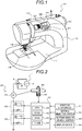
- Fig. 1 is a configuration diagram illustrating an outline of a configuration of a sewing machine 10
- Fig. 2 is an explanatory diagram illustrating an electric connection relation of a drive apparatus 20 for a sewing machine.
- the sewing machine 10 is configured to include a bed 11, a body 12 erected from the right end of the bed 11, and an arm 13 extending to the left in parallel to the bed 11 from an upper end of the body 12.
- a sewing needle 14 is provided at a tip end portion of the arm 13 so as to extend downward.
- the sewing needle 14 is connected to an upper shaft 50 (refer to Fig. 2 ) which is a main shaft extending from the tip end portion (left end portion) to the proximal end portion (right end portion) of the arm 13 via a needle rod (not shown), a crank mechanism, and the like.
- the rotary shaft of a DC motor 22 (refer to Fig. 2 ) is connected to the upper shaft 50 via a transmission mechanism, and the sewing needle 14 can move up and down by rotating the upper shaft 50 by the DC motor 22 and converting the rotational motion of the upper shaft 50 into the vertical motion of the needle rod by the crank mechanism.
- the sewing needle 14 is swingable in the right and left direction orthogonal to a cloth feed direction by a rocking mechanism (not shown) driven by the upper shaft 50.
- a rotary encoder 52 including a slit disk, a light emitting element and a light receiving element is attached to the upper shaft 50, and when a signal from the rotary encoder 52 is output to a controller 40, the controller 40 can calculate a rotation speed of the upper shaft 50, that is, a rotation speed V of the DC motor 22.
- the bed 11 is provided with a needle plate 15 and a shuttle device (not shown) in the lower side of the sewing needle 14.
- the shuttle device is driven by a driving force from a lower shaft (not shown) connected to the upper shaft 50 via a transmission mechanism so as to synchronously rotate with the upper shaft 50, and engages an upper thread and a lower thread to form a stitch by cooperation with the sewing needle 14.
- a vertical shuttle and a horizontal shuttle as the shuttle device.
- an operation panel 30 is provided on the front surface of the arm 13 as illustrated in Fig. 1 .
- the operation panel 30 is provided with a start or stop switch 31 which is pushed so as to start and stop the sewing, a setting selection switch 32 for switching various setting menus including setting a pattern type, setting the width of the pattern, setting the length of a stitch, and setting a sewing speed, a setting amount change switch (left switch and right switch) 33 for changing selection of the pattern and numerical values of the setting, and a display device (LED display device) 34 for display various pieces of information including the selected pattern and numerical values of the setting, a sewing speed, a warning display, an error display, and the like.
- a start or stop switch 31 which is pushed so as to start and stop the sewing
- a setting selection switch 32 for switching various setting menus including setting a pattern type, setting the width of the pattern, setting the length of a stitch, and setting a sewing speed
- a setting amount change switch (left switch and right switch) 33 for changing selection of the pattern and numerical values
- the drive apparatus 20 for a sewing machine is provided with the DC motor 22, a first drive circuit 24 and a second drive circuit 26 for driving the DC motor 22, and the controller 40.
- the first drive circuit 24 includes a first transistor T1 as a first semiconductor switching element connected to the DC motor 22 in series when viewed from a power supply 1.
- the second drive circuit 26 includes a second transistor T2 as a second semiconductor switching element connected to the DC motor 22 and the first transistor T1 in series when viewed from the power supply 1.
- a bipolar transistor, MOSFET, and IGBT can be used, for example.
- the power supply 1 is configured to include a commercial power supply 2 and a rectifier circuit 3 for rectifying an alternating current of the commercial power supply 2 to a direct current.
- the rectifier circuit 3 may be a full wave rectifier circuit, and may be a half wave rectifier circuit.
- the controller 40 is configured as a microprocessor centered on a CPU 41, and in addition to the CPU 41, is provided with a ROM 42 for storing a processing program, a RAM 43 functioning as a work memory, a timer 44, and an input and output port (not shown).
- a rotary position signal from the rotary encoder 52, an operation signal from the start or stop switch 31, an operation signal from the setting selection switch 32, and an operation signal from the setting amount change switch 33 are input to the controller 40 via an input port.
- the controller 40 outputs drive signals to the first drive circuit 24 (the first transistor T1) and the second drive circuit 26 (second transistor T2), and a display signal to the display device 34 via an output port.
- Fig. 3 is a flowchart illustrating an example of a sewing control routine executed by the CPU 41 of the controller 40
- Fig. 4 is a flowchart illustrating an example of a failure determination routine executed by the CPU 41 of the controller 40.
- These routines are repeatedly executed in parallel at predetermined time intervals (for example, every several milliseconds) during which the start or stop switch 31 is turned on and then the start or stop switch 31 is turned off.
- the sewing control routine will be described, and then the failure determination routine will be described.
- the CPU 41 of the controller 40 first, determines whether or not the error of the first drive circuit 24 or the second drive circuit 26 is determined in the failure determination routine described below (whether or not the error is occurring or not) (Step S100), and when determining that the error is occurring, the sewing control is not executed, and the sewing control routine is finished.
- the preparation period is a preparation period from the time when the start or stop switch 31 is turned on to the time when the sewing is started, and is predetermined, for example, as a period of about 100 to 200 msec.
- the low speed control period is a period for performing sewing start at a slow speed, and is predetermined, for example, as a period of about 500 to 1000 msec.
- the normal control period is a period during which the sewing motion is performed at the sewing speed instructed by the user, and is started after the low speed control period is finished.
- the sewing control routine is finished.
- the second drive circuit 26 is controlled so as to turn on the second transistor T2 (Step S140), the first transistor T1 is switching controlled by the duty ratio for rotating the DC motor 22 at a predetermined low rotation speed Vlo (Step S150), and thereby the sewing control routine is finished.
- the second drive circuit 26 is controlled so as to turn on the second transistor T2 (Step S160), the first transistor T1 is switching-controlled at the duty ratio for rotating the DC motor 22 at the command rotation speed Vtg corresponding to the command sewing speed commanded by the setting selection switch 32 and the setting amount change switch 33 (Step S170), and thereby the sewing control routine is finished.
- the failure determination routine When the failure determination routine is executed, the CPU 41 of the controller 40, first, determines whether or not it is during a first determination period (Step S200).
- the first determination period is a failure determination period which is defined as the same period as the above-described preparation period, and determines the abnormal rotation of the DC motor 22 in the preparation period, that is, a failure (short circuit) of the first transistor T1 and a failure (short circuit) of the second transistor T2.
- the failure determination period When determining that it is during the first determination period, it is determined whether or not it is during the failure determination period of the first transistor T1 (Step S210), and whether or not it is during the failure determination period of the second transistor T2 (Step S220).
- the failure determination period of the first transistor T1 and the failure determination period of the second transistor T2 are provided within the first determination period, and in the embodiment, it is set such that the failure determination period of the first transistor T1 is started when the first determination period is started, and the failure determination period of the second transistor T2 is started after the failure determination period of the first transistor T1 is finished.
- the first drive circuit 24 and the second drive circuit 26 are controlled so as to turn off the first transistor T1 and turn on the second transistor T2 (Step S230).
- the first drive circuit 24 and the second drive circuit 26 are controlled so as to turn on the first transistor T1 and turn off the second transistor T2 (Step S240).
- the first failure determination threshold Vth1 is a threshold for determining whether or not the DC motor 22 is rotated, and is defined as a value slightly higher than a value of 0.
- the first transistor T1 and the second transistor T2 are connected to the power supply 1 and the DC motor 22 in series, and thus when one of the switching elements is turned off, even when the other switching element is turned on, the DC motor 22 is not supposed to be rotated.
- the DC motor 22 is rotated. Accordingly, it is possible to determine whether or not one of the switching elements is failed by determining whether or not the DC motor 22 is rotated when one of the switching elements is turned off and the other switching element is turned on at the same time.
- Step S270 When determining that the rotation speed V of the DC motor 22 becomes greater than a first failure determination threshold Vht 1, and this situation is continuous during the first time t1, it is determined that there is a risk of failure (short circuit) in one of the switching elements, and in order to stop the abnormal rotation of the DC motor 22, the first drive circuit 24 and the second drive circuit 26 are controlled so as to turn off the first transistor T1 and the second transistor T2 (Step S270).
- the failure determination period of the first transistor T1 although the first drive circuit 24 is controlled so as to turn off the first transistor T1, from the situation where the DC motor 22 is rotated, it is determined that there is a risk of the failure (short circuit) in the first transistor T1.
- Step S280 the sewing speed abnormality and the warning display for warning the user that the abnormal rotation (the sewing speed) has occurred in the DC motor 22 are displayed on the display device 34 (Step S280).
- a warning counter C indicating warning counts is incremented by the value of 1 (Step S290) so as to determine whether or not the value of the warning counter C is greater than a threshold Cth (for example, 2, 3, or 4 times) (Step S300).
- the failure determination routine is once finished, and when the value of the warning counter C is determined to be higher than the threshold Cth, the failure (the failure of the first drive circuit 24 or the second drive circuit 26) of the first transistor T1 or the second transistor T2 is secured, the drive circuit abnormality and error display are displayed on the display device 34 (Step S310), and thereby the failure determination routine is finished.
- Step S100 of the above-described sewing control routine it is determined that the error is occurring, and thus any sewing motion will be prohibited regardless of the operation of start or stop switch 31.
- the rotation speed V of the DC motor 22 is equal to or less than the first failure determination threshold Vth1 in Step S250, and the situation is not continuous during the first time t1 in Step S260, it is determined whether or not it is during a second determination period (Step S320), and it is during the third determination period (Step S330).
- the second determination period is a failure determination period for mainly determining the failure (short circuit) of the first transistor T1 in the low speed control period.
- the second determination period is set to include a period from the start of the preparation period to the end of the low speed control period.
- the third determination period is set to include a period from the end of the second determination period until the end of the sewing motion is commanded (until the next start or stop switch 31 is turned off next).
- a second failure determination threshold Vth2 is set (Step S340), and it is determined whether the rotation speed V of the DC motor 22 is greater than the second failure determination threshold Vth2 (Step S350), and this situation is continuous during a second time t2 (for example, 50 to 100 msec) (Step S360).
- the second failure determination threshold Vth2 during the second determination period is defined as a higher speed than a low rotation speed Vlo which is the target rotation speed of the DC motor 22 in the low speed control, and in the embodiment, is defined as a half rotation speed of a rated maximum rotation speed Vmax of the DC motor 22.
- the first transistor T1 and the second transistor T2 are turned off so as to stop the abnormal rotation of the DC motor 22 and the sewing speed abnormality and warning display are displayed on the display device 34 (Steps S270 and S280).
- the warning counter C is incremented by the value of 1 (Step S290) so as to determine whether or not the value of the warning counter C is greater than the threshold Cth (Step S300).
- the failure determination routine is once finished, and when the value of the warning counter C is determined to be greater than the threshold Cth, the failure (short circuit) of the first transistor T1 is secured, the drive circuit abnormality and error display are displayed on the display device 34 (Step S310), and thereby the failure determination routine is finished.
- the second failure determination threshold Vth2 is set (Step S370), and it is determined whether the rotation speed V of the DC motor 22 is greater than the second failure determination threshold Vth2 (Step S380), and this situation is continuous during a third time t3 (for example, 50 to 100 msec) (Step S390).
- the second failure determination threshold Vth2 during the third determination period is defined as the higher speed than the command rotation speed Vtg which is the target rotation speed of the DC motor 22 in the normal control, and in the embodiment, is defined as a rotation speed obtained by adding the tolerance (maximum tolerance) ⁇ of the DC motor 22 to the rated maximum rotation speed Vmax of the DC motor 22.
- the first transistor T1 and the second transistor T2 are turned off so as to stop the abnormal rotation of the DC motor 22 and the sewing speed abnormality and warning display are displayed on the display device 34 (Steps S270 and S280).
- the warning counter C is incremented by the value of 1 (Step S290) so as to determine whether or not the value of the warning counter C is greater than the threshold Cth (Step S300).
- the failure determination routine is once finished, and when the value of the warning counter C is determined to be greater than the threshold Cth, the failure (short circuit) of the first transistor T1 is secured, the drive circuit abnormality and error display are displayed on the display device 34 (Step S310), and thereby the failure determination routine is finished.
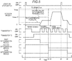
- Fig. 5 is an explanatory diagram illustrating changes of a rotation speed V and a switching state of transistors T1 and T2 of a DC motor 22 with time.
- the sewing control as illustrated in Fig. 5 , when the start of the sewing motion by turning on the start or stop switch 31 is commanded (time t1), after waiting for the preparation period to elapse (time t2), the low speed control in which the first transistor T1 is switched at a relatively small duty ratio is performed such that the second transistor T2 is turned on and the sewing is started at a low rotation speed Vlo.
- the normal control in which the first transistor T1 is switching-controlled at a duty ratio is performed such that the sewing speed becomes the command rotation speed Vtg commanded by the user in a state where the second transistor T2 is subsequently turned on.
- the stop of the sewing motion is commanded by turning off the start or stop switch 31 during the sewing motion (time t5)
- the first transistor T1 is switching-controlled at a small duty ratio, and the first transistor T1 at a predetermined timing (time t6) is turned off such that the sewing needle 14 is stopped at a position on the upper side, and then the second transistor T2 is turned off.
- the determination of each of the failures of the first transistor T1 and the second transistor T2 is executed during different aspects of periods such as the first determination period including the preparation period, the second determination period including the low speed control period, and the third determination period including the normal control period. That is, in the first determination period, when one of the first transistor T1 and the second transistor T2 is turned on and the other one is turned off, the determination of the failure is performed by determining whether or not the rotation speed V of the DC motor 22 is greater than the first failure determination threshold Vth1 which is slightly higher than the value of 0 (whether or not the DC motor 22 is rotated).
- the determination of the failure is performed by determining whether or not the rotation speed V of the DC motor 22 is greater than the second failure determination threshold Vth2 which is a half value of the rated maximum rotation speed Vmax. Further, in the third determination period, the determination of the failure is performed by determining whether or not the rotation speed V of the DC motor 22 is greater than the second failure determination threshold Vth2 obtained by adding the tolerance ⁇ of the DC motor 22 to the rated maximum rotation speed Vmax. As such, it is determined whether or not the abnormal rotation is occurring in the DC motor 22 by using different thresholds for each period, and thereby it is possible to appropriately determine the failure of the first drive circuit 24 or the second drive circuit 26 in the whole period. Particularly, the failure can be detected in the first determination period and the second determination period at the start, and thus the failure can be detected while the rotation of the upper shaft 50 and the DC motor 22 does not become excessively fast.
- the drive apparatus 20 for a sewing machine of the above-described example performs the sewing control in which the second drive circuit 26 is controlled so as to turn on the second transistor T2 and the first transistor T1 of the first drive circuit 24 is switching-controlled so as to drive the DC motor 22 at a target rotation speed. From the fact that the first transistor T1 and the second transistor T2 are connected to the power supply 1 and the DC motor 22 in series, even when one of the switching elements is short circuited, if the other switching element is turned off, it is possible to prevent the DC motor 22 from being driven with the abnormal rotation.
- the preparation period (the first determination period) during which the sewing control is started after the sewing motion is commanded, it is determined whether or not the DC motor 22 is rotated in a state where one of the switching element is turned on and the other switching element is turned off, and thus it is possible to preliminarily determine the risk of failure (short circuit) of the first transistor T1 and the second transistor T2 immediately before starting the sewing control.
- the risk of failure earlier than the low speed control period (the second determination period), the normal control period (the third determination period) (before the rotation of the upper shaft 50 and the DC motor 22 becomes faster).
- the preparation period (the first determination period) when it is determined that the DC motor 22 is rotated, the first transistor T1 and the second transistor T2 are turned off, and thus it is possible to prevent the sewing needle 14 from the being driven.
- the drive apparatus 20 for a sewing machine in the embodiment performs the low speed control for switching-controlling of the first transistor T1 such that the speed of sewing start becomes the low rotation speed Vlo in a state where the second transistor T2 is turned on, and at this time, when the rotation speed V of the DC motor 22 is higher than the half speed of the rated maximum rotation speed Vmax, the first transistor T1 and the second transistor T2 are turned off.
- the low speed control even during the execution of the low speed control, it is possible to determine the risk of the failure (short circuit) of the first transistor T1. That is, it is possible to determine the risk of the failure earlier than the normal control period (the third determination period) (before the rotation of the upper shaft 50 and the DC motor 22 becomes faster), thereby preventing the abnormal high speed rotation of the DC motor 22.
- the normal control in which the first transistor T1 is switching-controlling such that the sewing speed becomes the speed commanded by the user in the state where the second transistor T2 is turned on is executed, at this time, when the rotation speed V of the DC motor 22 is higher than the speed obtained by adding the tolerance ⁇ to the rated maximum rotation speed Vmax, the first transistor T1 and the second transistor T2 are turned off.
- the risk of the failure (short circuit) of the first transistor T1 thereby preventing the abnormal high speed rotation of the DC motor 22.
- the drive apparatus 20 for a sewing machine in the embodiment can appropriately warn the user against the risk of the failure of the first drive circuit 24 or the second drive circuit 26 by displaying the warning display on the display device 34.
- the warning count (warning counter C) reaches the threshold Cth, the error display is performed so as to prohibit the subsequent sewing control, and thereby it is possible to secure high safety.
- Fig. 6 is a flowchart illustrating a sewing control routine of a Modified example.
- the processes of the sewing control routine in the Modified example which are the same as those of the sewing control routine in the embodiment are denoted by the same step numbers, and description thereof will not be repeated.
- Step S100B when determining that the error is occurring in step S100, it is determined whether or not the switching element which is determined to be short-circuited is the first transistor T1 (Step S100B).
- Step S110B the process proceeds to Step S110B, and it is determined if it is during the preparation period, the low speed control period, or the normal control period (Steps S110B to S130B).
- Step S110B the sewing control routine is finished.
- the first drive circuit 24 When determining that it is during the low speed control period, the first drive circuit 24 is controlled so as to turn on the first transistor T1 and the second transistor T2 is switching-controlled so as to rotate the DC motor 22 at the low rotation speed Vlo (Steps S140B and S150B), the sewing control routine is finished.
- the first drive circuit 24 is controlled so as to turn on the first transistor T1 and the second transistor T2 is switching-controlled so as to rotate the DC motor 22 at the command rotation speed Vtg (Steps S160B and S170B), the sewing control routine is finished.
- Step S100B when determining that the switching element which is determined to be short-circuited is not the first transistor T1, that is, the switching element is the second transistor T2, similar to Steps S110 to S170 of the sewing control routine in the embodiment, during the preparation period, the sewing control routine is finished, and during the low speed control period or the normal control period, the first transistor T1 is switching-controlled such that the DC motor 22 is rotated at the rotation speed in response to each period in a state where the second transistor T2 is short-circuited (turned on), and thereby the sewing control routine is finished.
- the sewing control routine of the Modified example when the short circuit occurred any one of switching elements of the first transistor T1 and the second transistor T2, the sewing control is supposed to be performed by switching the other one of the switching elements, which is not short-circuited, in a state where the aforementioned one of the switching elements is short-circuited. With this, it is possible to appropriately perform the sewing control on the short circuit of one of the switching elements as well.
- the second failure determination threshold Vth is set to be the rotation speed which is the half of the rated maximum rotation speed Vmax of the DC motor 22; however, the second failure determination threshold is not limited to the aforementioned rotation speed. It may be set to be any the rotation speed as long as it is the rotation speed which is higher than the low rotation speed Vlo and is lower than the rated maximum rotation speed of the DC motor 22, for example, it may be set to be the value slightly higher than the low rotation speed Vlo which is the target rotation speed of the DC motor 22 in the low speed control.
- the second failure determination threshold Vth is set to be the speed obtained by adding the tolerance ⁇ of the DC motor 22 to the rated maximum rotation speed Vmax of the DC motor 22; however, the second failure determination threshold is not limited to the aforementioned rotation speed. For example, it may be set as the value slightly higher than the command rotation speed Vtg which is the target rotation speed of the DC motor 22 in the normal control.
- the second determination period for determining the failure of the first transistor T1 during the execution of the low speed control is set to be partially the same as the first determination period; however, the second determination period may be set not to be partially the same as the first determination period.
- the low speed control that controls the speed of the sewing start to be low is executed; however, the low speed control is not necessarily provided. In this case, there is no need to provide the processes in Steps S120, S140, and S150 of the sewing control routine in Fig. 3 and the processes in Steps S320 and S340 to S360 of the failure determination routine in Fig. 4 .
- the first drive circuit 24 and the second drive circuit 26 are controlled so as to turn on one of the switching elements and turn off the other switching element, and the first failure determination for determining whether or not the DC motor 22 is rotated is performed.
- the first failure determination may be performed in any type of period during which the sewing control is not executed.
- the short circuit failure of the first transistor T1 is determined by determining whether or not the rotation speed V of the DC motor 22 is greater than the second failure determination threshold Vth.
- an open failure of the first transistor T1 or the second transistor T2 may be determined by determining whether or not the rotation speed V of the DC motor 22 is lower than the target rotation speed (the low rotation speed Vlo, and the command rotation speed Vtg).
- the rotary encoder 52 (the rotation speed measuring unit) is attached to the upper shaft 50 connected to the DC motor 22 via the transmission mechanism; however, the member to which the rotary encoder 52 is attached is not limited.
- the rotary encoder 52 may be attached to the rotary shaft of the DC motor 22, or may be attached to any rotation member connected to the DC motor 22.
- the rotary encoder 52 is used as the rotation speed measuring unit for detecting the rotation speed of the DC motor 22; however, the rotation speed measuring unit is not limited thereto. For example, as long as it is possible to detect the rotation speed of the DC motor 22, any rotation speed measuring unit such as an electromagnetic pickup may be used.
- the first drive circuit 24 is provided with the first transistor T1 as the first semiconductor switching element which is connected to the DC motor 22 in series when viewed from the power supply 1
- the second drive circuit 26 is provided with the second transistor T2 as the second semiconductor switching element which is connected to the DC motor 22 and the first transistor T1 in series when viewed from the power supply 1, and as illustrated in Fig. 2 , the power supply 1, the DC motor 22, the first drive circuit 24, and the second drive circuit 26 are connected in series in this order from the top of Fig. 2 .
- the connection is not limited thereto.
- the power supply 1, the first drive circuit 24, the DC motor 22, and the second drive circuit 26 may be connected in series in this order from the top of Fig. 2
- the power supply 1, the first drive circuit 24, the second drive circuit 26, and the DC motor 22 may be connected in series in this order.
- the sewing needle 14 is driven by the DC motor 22, and the DC motor 22 is driven by the first drive circuit 24 and the second drive circuit 26; however, a configuration in which the sewing needle 14 is driven by an AC motor and the AC motor is driven by the first drive circuit and the second drive circuit may be applied.
- the DC motor 22 corresponds to the "motor”
- the first drive circuit 24 corresponds to the "first drive circuit”
- the second drive circuit 26 corresponds to the "second drive circuit”
- the controller 40 which calculates the rotation speed V of the DC motor 22 based on the signals from the rotary encoder 52 and the rotary encoder 52 corresponds to the "rotation speed measuring unit”
- the controller 40 which executes the sewing control routine and the failure determination routine corresponds to the "controller”.
- the correspondence between the main elements of the embodiment and the main elements of this disclosure described in the section of means for solving the problem is one example for specifically illustrating embodiment for carrying out this disclosure described in the section of means for solving the problem by example, and thus is not limited to the elements of this disclosure described in the section of the means for solving the problem. That is, the interpretation of this disclosure described in the section of the means for solving the problem is to be made based on the description in the aforementioned section, and the example is merely one specific example of this disclosure described in the section of the means for solving the problem.
- This disclosure can be used in the manufacturing industry of the drive apparatus for a sewing machine and the like.
Landscapes
- Engineering & Computer Science (AREA)
- Mechanical Engineering (AREA)
- Textile Engineering (AREA)
- Sewing Machines And Sewing (AREA)
- Control Of Electric Motors In General (AREA)
Abstract
Description
- This disclosure relates to a drive apparatus for sewing machine, more specifically relates to a drive apparatus for a sewing machine including a motor, a first drive circuit, a second drive circuit, a rotation measuring unit, and a controller.
- In the related art, such a drive apparatus for a sewing machine which is provided with a drive start switch provided in a drive circuit of a sewing machine motor, a speed adjustment circuit which includes a variable resistor for speed adjustment and a switching element cooperating with the variable resistor, a shutoff circuit which shuts off the drive circuit in a case where the switching element is short-circuited has been proposed (for example, refer to
JP 2006-34674A - However, in the above-described drive apparatus for a sewing machine, the electric resistor of the shutoff circuit is connected to the drive start switch in parallel, and thus the shutoff circuit can only detect the short circuit of the switching element when a foot controller is not operated. For this reason, when the user operates the foot controller, even when the switching element is short-circuited, it is not possible to prevent the abnormal high speed rotation of the sewing machine motor. In addition, in the above-described drive apparatus for a sewing machine, even when the drive start switch is turned off, a minute current flows into the electric resistor connected in parallel with the drive start switch, and thus energy efficiency is deteriorated.
- Thus, a need exists for a drive apparatus for a sewing machine capable of appropriately determining a failure of the drive circuit and preventing the abnormal driving of a sewing needle.
- A drive apparatus for a sewing machine according to an aspect of this disclosure adopts configurations described below.
- A drive apparatus for a sewing machine according to an aspect of this disclosure includes a motor that drives a sewing needle; a first drive circuit that includes a first switching element which is connected to the motor in series when viewed from a power supply; a second drive circuit that includes a second switching element which is connected to the motor and the first switching element in series when viewed from the power supply; a rotation speed measuring unit that measures a rotation speed of the motor; and a controller that performs a sewing control when a sewing motion is commanded, in which the second drive circuit is controlled so as to turn on the second switching element, and the first drive circuit is controlled so as to drive the motor at a target rotation speed by switching the first switching element, in a predetermined period during which the sewing control is not executed, controls the first drive circuit and the second drive circuit such that one of the switching elements of the first switching element and the second switching element is turned on and the other switching element is turned off, and determines a first failure determination that determines a short circuit failure of the first drive circuit or the second drive circuit based on whether or not the rotation of the motor is detected by the rotation speed measuring unit.
- The drive apparatus for a sewing machine according to the aspect of this disclosure is provided with the motor, the first drive circuit that includes the first switching element, the second drive circuit that includes the second switching element, the rotation speed measuring unit, and the controller. When the sewing motion is commanded, the controller performs a sewing control in which the second drive circuit is controlled so as to turn on the second switching element and the first drive circuit is controlled so as to drive the motor at a target rotation speed by switching the first switching element. The first switching element and the second switching element are connected to the power supply and the motor in series. For this reason, even if one switching element is short-circuited, it is possible to prevent the motor from being driven at an abnormal speed by turning off the other switching element. Further, in a predetermined period during which the sewing control is not executed, the controller controls the first drive circuit and the second drive circuit such that one of the switching elements of the first switching element and the second switching element is turned on and the other switching element is turned off, and determines a short circuit failure of the first drive circuit or the second drive circuit based on whether or not the rotation of the motor is detected by the rotation speed measuring unit. With this, it is possible to appropriately determine the short circuit failure of the first drive circuit or the second drive circuit by using the rotation speed measuring unit.
- In the drive apparatus for a sewing machine according to the aspect of this disclosure, the first failure determination may be performed in the predetermined period during which the sewing control is started after the sewing motion is commanded. With this configuration, it is possible to preliminarily determine the failure of the first drive circuit or the second drive circuit before starting the sewing control.
- In the drive apparatus for a sewing machine according to the aspect of this disclosure, as the sewing control, the controller may perform a low speed control in which the first drive circuit and the second drive circuit are controlled so as to drive the motor at a predetermined rotation speed lower than the target rotation speed for a predetermined time, and then perform a normal control in which the first drive circuit and the second drive circuit are controlled so as to drive the motor at the target rotation speed, at least during execution of the low speed control, perform a second failure determination in which a short circuit failure of the first drive circuit is determined based on whether or not a rotation speed measured by the rotation speed measuring unit is higher than a first rotation speed which is higher than the predetermined rotation speed and is lower than a rated maximum rotation speed of the motor, and at least during execution of the low speed control, control the second drive circuit so as to turn off the second switching element when the rotation speed is higher than the first rotation speed. With this configuration, it is possible to appropriately determine the failure of the first drive circuit before starting the normal control. In addition, even when the first drive circuit failed to be short-circuited during the execution of the low speed control, it is possible to prevent the sewing needle from being driven at an abnormal speed.
- In the drive apparatus for a sewing machine according to the aspect of this disclosure, the controller may perform a third failure determination in which a short circuit failure of the first drive circuit is determined based on whether or not the rotation speed measured by the rotation speed measuring unit is higher than a second rotation speed which is higher than the target rotation speed during the execution of the sewing control, and control the second drive circuit so as to turn off the second switching element when the rotation speed is higher than the second rotation speed during the execution of the sewing control. With this configuration, it is possible to appropriately determine the failure of the first drive circuit during the execution of the normal control. In addition, even when the first drive circuit fails to be short-circuited during the execution of the normal control, it is possible to prevent the sewing needle from being driven at an abnormal speed.
- In the drive apparatus for a sewing machine according to the aspect of this disclosure, in a case where it is determined that the first switching element is short-circuited, as the sewing control, the controller may control the second drive circuit so as to drive the motor at the target rotation speed by switching the second switching element. With this configuration, even when a short circuit failure occurs in the first drive circuit, it is possible to appropriately execute the sewing motion by the second drive circuit.
- In the drive apparatus for a sewing machine according to the aspect of this disclosure, a display device which is capable of displaying predetermined information may be further included, in which the controller performs a predetermined warning display on the display device when an abnormal rotation of the motor is detected by the rotation speed measuring unit. With this configuration, when there is a risk of the failure in the first drive circuit or the second drive circuit, it is possible to appropriately warn the user against the risk of the failure.
- The foregoing and additional features and characteristics of this disclosure will become more apparent from the following detailed description considered with the reference to the accompanying drawings, wherein:
-
Fig. 1 a configuration diagram illustrating an outline of a configuration of a sewing machine; -
Fig. 2 is an explanatory diagram illustrating an electric connection relation of a drive apparatus for a sewing machine; -
Fig. 3 is a flowchart illustrating an example of a sewing control routine; -
Fig. 4 is a flowchart illustrating an example of a failure determination routine; -
Fig. 5 is an explanatory diagram illustrating changes of a rotation speed and a switching state of transistors of a DC motor with time; and -
Fig. 6 is a flowchart illustrating a sewing control routine in Modified example. - Embodiments of this disclosure will be described with reference to embodiments.
-
Fig. 1 is a configuration diagram illustrating an outline of a configuration of asewing machine 10, andFig. 2 is an explanatory diagram illustrating an electric connection relation of adrive apparatus 20 for a sewing machine. As illustrated inFig. 1 , thesewing machine 10 is configured to include abed 11, abody 12 erected from the right end of thebed 11, and anarm 13 extending to the left in parallel to thebed 11 from an upper end of thebody 12. - A
sewing needle 14 is provided at a tip end portion of thearm 13 so as to extend downward. Thesewing needle 14 is connected to an upper shaft 50 (refer toFig. 2 ) which is a main shaft extending from the tip end portion (left end portion) to the proximal end portion (right end portion) of thearm 13 via a needle rod (not shown), a crank mechanism, and the like. The rotary shaft of a DC motor 22 (refer toFig. 2 ) is connected to theupper shaft 50 via a transmission mechanism, and thesewing needle 14 can move up and down by rotating theupper shaft 50 by theDC motor 22 and converting the rotational motion of theupper shaft 50 into the vertical motion of the needle rod by the crank mechanism. In addition, thesewing needle 14 is swingable in the right and left direction orthogonal to a cloth feed direction by a rocking mechanism (not shown) driven by theupper shaft 50. Further, as illustrated inFig. 2 , arotary encoder 52 including a slit disk, a light emitting element and a light receiving element is attached to theupper shaft 50, and when a signal from therotary encoder 52 is output to acontroller 40, thecontroller 40 can calculate a rotation speed of theupper shaft 50, that is, a rotation speed V of theDC motor 22. - The
bed 11 is provided with aneedle plate 15 and a shuttle device (not shown) in the lower side of thesewing needle 14. The shuttle device is driven by a driving force from a lower shaft (not shown) connected to theupper shaft 50 via a transmission mechanism so as to synchronously rotate with theupper shaft 50, and engages an upper thread and a lower thread to form a stitch by cooperation with thesewing needle 14. Note that, it is possible to use a vertical shuttle and a horizontal shuttle as the shuttle device. - In addition, an
operation panel 30 is provided on the front surface of thearm 13 as illustrated inFig. 1 . Theoperation panel 30 is provided with a start orstop switch 31 which is pushed so as to start and stop the sewing, asetting selection switch 32 for switching various setting menus including setting a pattern type, setting the width of the pattern, setting the length of a stitch, and setting a sewing speed, a setting amount change switch (left switch and right switch) 33 for changing selection of the pattern and numerical values of the setting, and a display device (LED display device) 34 for display various pieces of information including the selected pattern and numerical values of the setting, a sewing speed, a warning display, an error display, and the like. In the embodiment, in a case of setting the sewing speed, when a user pushes the left switch of the settingamount change switch 33 after switching the setting menu over the setting of the sewing speed by thesetting selection switch 32, it is possible to specify the slower sewing speed, and when the right switch is pushed, it is possible to specify the faster sewing speed. - In the embodiment, as illustrated in
Fig. 2 , thedrive apparatus 20 for a sewing machine is provided with theDC motor 22, afirst drive circuit 24 and asecond drive circuit 26 for driving theDC motor 22, and thecontroller 40. Thefirst drive circuit 24 includes a first transistor T1 as a first semiconductor switching element connected to theDC motor 22 in series when viewed from apower supply 1. Thesecond drive circuit 26 includes a second transistor T2 as a second semiconductor switching element connected to theDC motor 22 and the first transistor T1 in series when viewed from thepower supply 1. Note that, as the first transistor T1 and the second transistor T2, a bipolar transistor, MOSFET, and IGBT can be used, for example. Thepower supply 1 is configured to include acommercial power supply 2 and arectifier circuit 3 for rectifying an alternating current of thecommercial power supply 2 to a direct current. Therectifier circuit 3 may be a full wave rectifier circuit, and may be a half wave rectifier circuit. - The
controller 40 is configured as a microprocessor centered on aCPU 41, and in addition to theCPU 41, is provided with aROM 42 for storing a processing program, aRAM 43 functioning as a work memory, atimer 44, and an input and output port (not shown). A rotary position signal from therotary encoder 52, an operation signal from the start orstop switch 31, an operation signal from thesetting selection switch 32, and an operation signal from the settingamount change switch 33 are input to thecontroller 40 via an input port. Further, thecontroller 40 outputs drive signals to the first drive circuit 24 (the first transistor T1) and the second drive circuit 26 (second transistor T2), and a display signal to thedisplay device 34 via an output port. - Next, the operation of the
drive apparatus 20 for a sewing machine configured as above will be described.Fig. 3 is a flowchart illustrating an example of a sewing control routine executed by theCPU 41 of thecontroller 40, andFig. 4 is a flowchart illustrating an example of a failure determination routine executed by theCPU 41 of thecontroller 40. These routines are repeatedly executed in parallel at predetermined time intervals (for example, every several milliseconds) during which the start or stopswitch 31 is turned on and then the start or stopswitch 31 is turned off. First, the sewing control routine will be described, and then the failure determination routine will be described. - When the sewing control routine is executed, the
CPU 41 of thecontroller 40, first, determines whether or not the error of thefirst drive circuit 24 or thesecond drive circuit 26 is determined in the failure determination routine described below (whether or not the error is occurring or not) (Step S100), and when determining that the error is occurring, the sewing control is not executed, and the sewing control routine is finished. - On the other hand, when it is determined that the error is not occurring, it is determined whether or not it is during the preparation period (Step S110), whether or not it is during the low speed control period (Step S120), and whether or not it is during the normal control period (Step S130). Here, the preparation period is a preparation period from the time when the start or stop
switch 31 is turned on to the time when the sewing is started, and is predetermined, for example, as a period of about 100 to 200 msec. The low speed control period is a period for performing sewing start at a slow speed, and is predetermined, for example, as a period of about 500 to 1000 msec. The normal control period is a period during which the sewing motion is performed at the sewing speed instructed by the user, and is started after the low speed control period is finished. When determining that it is during the preparation period, the sewing control routine is finished. When determining that it is during the low speed control period, thesecond drive circuit 26 is controlled so as to turn on the second transistor T2 (Step S140), the first transistor T1 is switching controlled by the duty ratio for rotating theDC motor 22 at a predetermined low rotation speed Vlo (Step S150), and thereby the sewing control routine is finished. In addition, when determining that it is in the normal control period, thesecond drive circuit 26 is controlled so as to turn on the second transistor T2 (Step S160), the first transistor T1 is switching-controlled at the duty ratio for rotating theDC motor 22 at the command rotation speed Vtg corresponding to the command sewing speed commanded by the settingselection switch 32 and the setting amount change switch 33 (Step S170), and thereby the sewing control routine is finished. - Next, the failure determination routine will be described. When the failure determination routine is executed, the
CPU 41 of thecontroller 40, first, determines whether or not it is during a first determination period (Step S200). Here, the first determination period is a failure determination period which is defined as the same period as the above-described preparation period, and determines the abnormal rotation of theDC motor 22 in the preparation period, that is, a failure (short circuit) of the first transistor T1 and a failure (short circuit) of the second transistor T2. When determining that it is during the first determination period, it is determined whether or not it is during the failure determination period of the first transistor T1 (Step S210), and whether or not it is during the failure determination period of the second transistor T2 (Step S220). Note that, the failure determination period of the first transistor T1 and the failure determination period of the second transistor T2 are provided within the first determination period, and in the embodiment, it is set such that the failure determination period of the first transistor T1 is started when the first determination period is started, and the failure determination period of the second transistor T2 is started after the failure determination period of the first transistor T1 is finished. When determining that it is during the failure determination period of the first transistor T1, thefirst drive circuit 24 and thesecond drive circuit 26 are controlled so as to turn off the first transistor T1 and turn on the second transistor T2 (Step S230). On the other hand, when determining that it is during the failure determination period of the second transistor T2, thefirst drive circuit 24 and thesecond drive circuit 26 are controlled so as to turn on the first transistor T1 and turn off the second transistor T2 (Step S240). - When one of the first transistor T1 and the second transistor T2 is turned on and the other one is turned off, it is determined whether or not the rotation speed V of the
DC motor 22 becomes greater than a first failure determination threshold Vth1 (Step S250), and this situation is continuous during a first time t1 (for example, 10 to 20 msec) (Step S260). Here, the first failure determination threshold Vth1 is a threshold for determining whether or not theDC motor 22 is rotated, and is defined as a value slightly higher than a value of 0. As described above, the first transistor T1 and the second transistor T2 are connected to thepower supply 1 and theDC motor 22 in series, and thus when one of the switching elements is turned off, even when the other switching element is turned on, theDC motor 22 is not supposed to be rotated. However, in a case where one of the switching elements is short-circuited, when the other switching element is turned on, theDC motor 22 is rotated. Accordingly, it is possible to determine whether or not one of the switching elements is failed by determining whether or not theDC motor 22 is rotated when one of the switching elements is turned off and the other switching element is turned on at the same time. - When determining that the rotation speed V of the
DC motor 22 becomes greater than a first failuredetermination threshold Vht 1, and this situation is continuous during the first time t1, it is determined that there is a risk of failure (short circuit) in one of the switching elements, and in order to stop the abnormal rotation of theDC motor 22, thefirst drive circuit 24 and thesecond drive circuit 26 are controlled so as to turn off the first transistor T1 and the second transistor T2 (Step S270). Here, in the failure determination period of the first transistor T1, although thefirst drive circuit 24 is controlled so as to turn off the first transistor T1, from the situation where theDC motor 22 is rotated, it is determined that there is a risk of the failure (short circuit) in the first transistor T1. Further, in the failure determination period of the second transistor T2, although thesecond drive circuit 26 is controlled so as to turn off the second transistor T2, from the situation where theDC motor 22 is rotated, it is determined that there is a risk of the failure (short circuit) in the second transistor T2. Subsequently, the sewing speed abnormality and the warning display for warning the user that the abnormal rotation (the sewing speed) has occurred in theDC motor 22 are displayed on the display device 34 (Step S280). In addition, a warning counter C indicating warning counts is incremented by the value of 1 (Step S290) so as to determine whether or not the value of the warning counter C is greater than a threshold Cth (for example, 2, 3, or 4 times) (Step S300). When the value of the warning counter C is determined to be equal to or less than threshold Cth, the failure determination routine is once finished, and when the value of the warning counter C is determined to be higher than the threshold Cth, the failure (the failure of thefirst drive circuit 24 or the second drive circuit 26) of the first transistor T1 or the second transistor T2 is secured, the drive circuit abnormality and error display are displayed on the display device 34 (Step S310), and thereby the failure determination routine is finished. With this, in Step S100 of the above-described sewing control routine, it is determined that the error is occurring, and thus any sewing motion will be prohibited regardless of the operation of start or stopswitch 31. - When determining that it is not during the first determination period in Step S200, it is neither the failure determination period of the first transistor T1 nor the failure determination period of the second transistor T2 in Steps S210 and S220, the rotation speed V of the
DC motor 22 is equal to or less than the first failure determination threshold Vth1 in Step S250, and the situation is not continuous during the first time t1 in Step S260, it is determined whether or not it is during a second determination period (Step S320), and it is during the third determination period (Step S330). Here, the second determination period is a failure determination period for mainly determining the failure (short circuit) of the first transistor T1 in the low speed control period. In the embodiment, the second determination period is set to include a period from the start of the preparation period to the end of the low speed control period. In addition, the third determination period is set to include a period from the end of the second determination period until the end of the sewing motion is commanded (until the next start or stopswitch 31 is turned off next). - When determining that it is during the second determination period in Step S320, a second failure determination threshold Vth2 is set (Step S340), and it is determined whether the rotation speed V of the
DC motor 22 is greater than the second failure determination threshold Vth2 (Step S350), and this situation is continuous during a second time t2 (for example, 50 to 100 msec) (Step S360). Here, the second failure determination threshold Vth2 during the second determination period is defined as a higher speed than a low rotation speed Vlo which is the target rotation speed of theDC motor 22 in the low speed control, and in the embodiment, is defined as a half rotation speed of a rated maximum rotation speed Vmax of theDC motor 22. Even when the rotation speed V of theDC motor 22 is determined to be equal to or less than the second failure determination threshold Vth2, or the rotation speed V of theDC motor 22 is greater than the second failure determination threshold Vth2, if this situation is not continuous during the second time t2, the failure determination routine is finished. On the other hand, when the rotation speed V of theDC motor 22 is greater than the second failure determination threshold Vth2, and this situation is continuous during the second time t2, it is determined that there is a risk of the failure (short circuit) in the first transistor T1, and the process proceeds to Step S270. Then, the first transistor T1 and the second transistor T2 are turned off so as to stop the abnormal rotation of theDC motor 22 and the sewing speed abnormality and warning display are displayed on the display device 34 (Steps S270 and S280). Subsequently, the warning counter C is incremented by the value of 1 (Step S290) so as to determine whether or not the value of the warning counter C is greater than the threshold Cth (Step S300). When the value of the warning counter C is determined to be equal to or less than threshold Cth, the failure determination routine is once finished, and when the value of the warning counter C is determined to be greater than the threshold Cth, the failure (short circuit) of the first transistor T1 is secured, the drive circuit abnormality and error display are displayed on the display device 34 (Step S310), and thereby the failure determination routine is finished. - When determining that it is during a third determination period in Step S330, the second failure determination threshold Vth2 is set (Step S370), and it is determined whether the rotation speed V of the
DC motor 22 is greater than the second failure determination threshold Vth2 (Step S380), and this situation is continuous during a third time t3 (for example, 50 to 100 msec) (Step S390). Here, the second failure determination threshold Vth2 during the third determination period is defined as the higher speed than the command rotation speed Vtg which is the target rotation speed of theDC motor 22 in the normal control, and in the embodiment, is defined as a rotation speed obtained by adding the tolerance (maximum tolerance) α of theDC motor 22 to the rated maximum rotation speed Vmax of theDC motor 22. Even when the rotation speed V of theDC motor 22 is determined to be equal to or less than the second failure determination threshold Vth2, or the rotation speed V of theDC motor 22 is greater than the second failure determination threshold Vth2, if this situation is determined not to be continuous during the third time t3, the failure determination routine is finished. On the other hand, when it is determined that the rotation speed V of theDC motor 22 is greater than the second failure determination threshold Vth2, and this situation is continuous during the third time t3, it is determined that there is a risk of the failure (short circuit) in the first transistor T1, and the process proceeds to Step S270. Then, the first transistor T1 and the second transistor T2 are turned off so as to stop the abnormal rotation of theDC motor 22 and the sewing speed abnormality and warning display are displayed on the display device 34 (Steps S270 and S280). Subsequently, the warning counter C is incremented by the value of 1 (Step S290) so as to determine whether or not the value of the warning counter C is greater than the threshold Cth (Step S300). When the value of the warning counter C is determined to be equal to or less than threshold Cth, the failure determination routine is once finished, and when the value of the warning counter C is determined to be greater than the threshold Cth, the failure (short circuit) of the first transistor T1 is secured, the drive circuit abnormality and error display are displayed on the display device 34 (Step S310), and thereby the failure determination routine is finished. -
Fig. 5 is an explanatory diagram illustrating changes of a rotation speed V and a switching state of transistors T1 and T2 of aDC motor 22 with time. In the sewing control, as illustrated inFig. 5 , when the start of the sewing motion by turning on the start or stopswitch 31 is commanded (time t1), after waiting for the preparation period to elapse (time t2), the low speed control in which the first transistor T1 is switched at a relatively small duty ratio is performed such that the second transistor T2 is turned on and the sewing is started at a low rotation speed Vlo. When the low speed control period has elapsed (time t4), the normal control in which the first transistor T1 is switching-controlled at a duty ratio is performed such that the sewing speed becomes the command rotation speed Vtg commanded by the user in a state where the second transistor T2 is subsequently turned on. In addition, when the stop of the sewing motion is commanded by turning off the start or stopswitch 31 during the sewing motion (time t5), the first transistor T1 is switching-controlled at a small duty ratio, and the first transistor T1 at a predetermined timing (time t6) is turned off such that thesewing needle 14 is stopped at a position on the upper side, and then the second transistor T2 is turned off. The determination of each of the failures of the first transistor T1 and the second transistor T2 is executed during different aspects of periods such as the first determination period including the preparation period, the second determination period including the low speed control period, and the third determination period including the normal control period. That is, in the first determination period, when one of the first transistor T1 and the second transistor T2 is turned on and the other one is turned off, the determination of the failure is performed by determining whether or not the rotation speed V of theDC motor 22 is greater than the first failure determination threshold Vth1 which is slightly higher than the value of 0 (whether or not theDC motor 22 is rotated). In addition, in the second determination period, the determination of the failure is performed by determining whether or not the rotation speed V of theDC motor 22 is greater than the second failure determination threshold Vth2 which is a half value of the rated maximum rotation speed Vmax. Further, in the third determination period, the determination of the failure is performed by determining whether or not the rotation speed V of theDC motor 22 is greater than the second failure determination threshold Vth2 obtained by adding the tolerance α of theDC motor 22 to the rated maximum rotation speed Vmax. As such, it is determined whether or not the abnormal rotation is occurring in theDC motor 22 by using different thresholds for each period, and thereby it is possible to appropriately determine the failure of thefirst drive circuit 24 or thesecond drive circuit 26 in the whole period. Particularly, the failure can be detected in the first determination period and the second determination period at the start, and thus the failure can be detected while the rotation of theupper shaft 50 and theDC motor 22 does not become excessively fast. - When the sewing motion is commanded, the
drive apparatus 20 for a sewing machine of the above-described example performs the sewing control in which thesecond drive circuit 26 is controlled so as to turn on the second transistor T2 and the first transistor T1 of thefirst drive circuit 24 is switching-controlled so as to drive theDC motor 22 at a target rotation speed. From the fact that the first transistor T1 and the second transistor T2 are connected to thepower supply 1 and theDC motor 22 in series, even when one of the switching elements is short circuited, if the other switching element is turned off, it is possible to prevent theDC motor 22 from being driven with the abnormal rotation. In addition, in the preparation period (the first determination period) during which the sewing control is started after the sewing motion is commanded, it is determined whether or not theDC motor 22 is rotated in a state where one of the switching element is turned on and the other switching element is turned off, and thus it is possible to preliminarily determine the risk of failure (short circuit) of the first transistor T1 and the second transistor T2 immediately before starting the sewing control. In other words, it is possible to determine the risk of failure earlier than the low speed control period (the second determination period), the normal control period (the third determination period) (before the rotation of theupper shaft 50 and theDC motor 22 becomes faster). In addition, in the preparation period (the first determination period), when it is determined that theDC motor 22 is rotated, the first transistor T1 and the second transistor T2 are turned off, and thus it is possible to prevent thesewing needle 14 from the being driven. - Further, the
drive apparatus 20 for a sewing machine in the embodiment performs the low speed control for switching-controlling of the first transistor T1 such that the speed of sewing start becomes the low rotation speed Vlo in a state where the second transistor T2 is turned on, and at this time, when the rotation speed V of theDC motor 22 is higher than the half speed of the rated maximum rotation speed Vmax, the first transistor T1 and the second transistor T2 are turned off. With this, even during the execution of the low speed control, it is possible to determine the risk of the failure (short circuit) of the first transistor T1. That is, it is possible to determine the risk of the failure earlier than the normal control period (the third determination period) (before the rotation of theupper shaft 50 and theDC motor 22 becomes faster), thereby preventing the abnormal high speed rotation of theDC motor 22. - Further, according to the
drive apparatus 20 for a sewing machine in the embodiment, the normal control in which the first transistor T1 is switching-controlling such that the sewing speed becomes the speed commanded by the user in the state where the second transistor T2 is turned on is executed, at this time, when the rotation speed V of theDC motor 22 is higher than the speed obtained by adding the tolerance α to the rated maximum rotation speed Vmax, the first transistor T1 and the second transistor T2 are turned off. With this, even during the execution of the normal control, it is possible to determine the risk of the failure (short circuit) of the first transistor T1, thereby preventing the abnormal high speed rotation of theDC motor 22. - In addition, when the abnormal rotation (abnormality of the sewing speed) of the
DC motor 22 is determined, thedrive apparatus 20 for a sewing machine in the embodiment can appropriately warn the user against the risk of the failure of thefirst drive circuit 24 or thesecond drive circuit 26 by displaying the warning display on thedisplay device 34. In addition, when the warning count (warning counter C) reaches the threshold Cth, the error display is performed so as to prohibit the subsequent sewing control, and thereby it is possible to secure high safety. - In the
drive apparatus 20 for a sewing machine in the embodiment, the sewing control is prohibited while the error is occurring; however, the sewing control may be allowed to be executed even while the error is occurring.Fig. 6 is a flowchart illustrating a sewing control routine of a Modified example. The processes of the sewing control routine in the Modified example which are the same as those of the sewing control routine in the embodiment are denoted by the same step numbers, and description thereof will not be repeated. - In the sewing control routine of the Modified example, when determining that the error is occurring in step S100, it is determined whether or not the switching element which is determined to be short-circuited is the first transistor T1 (Step S100B). When determining that the switching element which is determined to be short-circuited is the first transistor T1, the process proceeds to Step S110B, and it is determined if it is during the preparation period, the low speed control period, or the normal control period (Steps S110B to S130B). When determining that it is during the preparation period, the sewing control routine is finished. When determining that it is during the low speed control period, the
first drive circuit 24 is controlled so as to turn on the first transistor T1 and the second transistor T2 is switching-controlled so as to rotate theDC motor 22 at the low rotation speed Vlo (Steps S140B and S150B), the sewing control routine is finished. When determining that it is during the normal control period, thefirst drive circuit 24 is controlled so as to turn on the first transistor T1 and the second transistor T2 is switching-controlled so as to rotate theDC motor 22 at the command rotation speed Vtg (Steps S160B and S170B), the sewing control routine is finished. - In Step S100B, when determining that the switching element which is determined to be short-circuited is not the first transistor T1, that is, the switching element is the second transistor T2, similar to Steps S110 to S170 of the sewing control routine in the embodiment, during the preparation period, the sewing control routine is finished, and during the low speed control period or the normal control period, the first transistor T1 is switching-controlled such that the
DC motor 22 is rotated at the rotation speed in response to each period in a state where the second transistor T2 is short-circuited (turned on), and thereby the sewing control routine is finished. - As such, in the sewing control routine of the Modified example, when the short circuit occurred any one of switching elements of the first transistor T1 and the second transistor T2, the sewing control is supposed to be performed by switching the other one of the switching elements, which is not short-circuited, in a state where the aforementioned one of the switching elements is short-circuited. With this, it is possible to appropriately perform the sewing control on the short circuit of one of the switching elements as well.
- In the
drive apparatus 20 for a sewing machine in the embodiment, during the execution of the low speed control, the second failure determination threshold Vth is set to be the rotation speed which is the half of the rated maximum rotation speed Vmax of theDC motor 22; however, the second failure determination threshold is not limited to the aforementioned rotation speed. It may be set to be any the rotation speed as long as it is the rotation speed which is higher than the low rotation speed Vlo and is lower than the rated maximum rotation speed of theDC motor 22, for example, it may be set to be the value slightly higher than the low rotation speed Vlo which is the target rotation speed of theDC motor 22 in the low speed control. - In the
drive apparatus 20 for a sewing machine in the embodiment, during the execution of the normal control, the second failure determination threshold Vth is set to be the speed obtained by adding the tolerance α of theDC motor 22 to the rated maximum rotation speed Vmax of theDC motor 22; however, the second failure determination threshold is not limited to the aforementioned rotation speed. For example, it may be set as the value slightly higher than the command rotation speed Vtg which is the target rotation speed of theDC motor 22 in the normal control. - In the
drive apparatus 20 for a sewing machine in the embodiment, the second determination period for determining the failure of the first transistor T1 during the execution of the low speed control is set to be partially the same as the first determination period; however, the second determination period may be set not to be partially the same as the first determination period. - In the
drive apparatus 20 for a sewing machine in the embodiment, in the sewing control, the low speed control that controls the speed of the sewing start to be low is executed; however, the low speed control is not necessarily provided. In this case, there is no need to provide the processes in Steps S120, S140, and S150 of the sewing control routine inFig. 3 and the processes in Steps S320 and S340 to S360 of the failure determination routine inFig. 4 . - In the
drive apparatus 20 for a sewing machine in the embodiment, in the preparation period during which the sewing control is started after the sewing motion is commanded, thefirst drive circuit 24 and thesecond drive circuit 26 are controlled so as to turn on one of the switching elements and turn off the other switching element, and the first failure determination for determining whether or not theDC motor 22 is rotated is performed. However, the first failure determination may be performed in any type of period during which the sewing control is not executed. - In the
drive apparatus 20 for a sewing machine in the embodiment, during the execution of the low speed control or the normal control, the short circuit failure of the first transistor T1 is determined by determining whether or not the rotation speed V of theDC motor 22 is greater than the second failure determination threshold Vth. However, an open failure of the first transistor T1 or the second transistor T2 may be determined by determining whether or not the rotation speed V of theDC motor 22 is lower than the target rotation speed (the low rotation speed Vlo, and the command rotation speed Vtg). - In the
drive apparatus 20 for a sewing machine in the embodiment, the rotary encoder 52 (the rotation speed measuring unit) is attached to theupper shaft 50 connected to theDC motor 22 via the transmission mechanism; however, the member to which therotary encoder 52 is attached is not limited. For example, therotary encoder 52 may be attached to the rotary shaft of theDC motor 22, or may be attached to any rotation member connected to theDC motor 22. - In the
drive apparatus 20 for a sewing machine in the embodiment, therotary encoder 52 is used as the rotation speed measuring unit for detecting the rotation speed of theDC motor 22; however, the rotation speed measuring unit is not limited thereto. For example, as long as it is possible to detect the rotation speed of theDC motor 22, any rotation speed measuring unit such as an electromagnetic pickup may be used. - In the
drive apparatus 20 for a sewing machine in the embodiment, thefirst drive circuit 24 is provided with the first transistor T1 as the first semiconductor switching element which is connected to theDC motor 22 in series when viewed from thepower supply 1, and thesecond drive circuit 26 is provided with the second transistor T2 as the second semiconductor switching element which is connected to theDC motor 22 and the first transistor T1 in series when viewed from thepower supply 1, and as illustrated inFig. 2 , thepower supply 1, theDC motor 22, thefirst drive circuit 24, and thesecond drive circuit 26 are connected in series in this order from the top ofFig. 2 . However, the connection is not limited thereto. For example, thepower supply 1, thefirst drive circuit 24, theDC motor 22, and thesecond drive circuit 26 may be connected in series in this order from the top ofFig. 2 , or thepower supply 1, thefirst drive circuit 24, thesecond drive circuit 26, and theDC motor 22 may be connected in series in this order. - In the
drive apparatus 20 for a sewing machine in the embodiment, thesewing needle 14 is driven by theDC motor 22, and theDC motor 22 is driven by thefirst drive circuit 24 and thesecond drive circuit 26; however, a configuration in which thesewing needle 14 is driven by an AC motor and the AC motor is driven by the first drive circuit and the second drive circuit may be applied. - The correspondence between the main elements of the embodiment and the main elements of this disclosure described in the section of means for solving the problem will be described. In the embodiment, the
DC motor 22 corresponds to the "motor", thefirst drive circuit 24 corresponds to the "first drive circuit", thesecond drive circuit 26 corresponds to the "second drive circuit", thecontroller 40 which calculates the rotation speed V of theDC motor 22 based on the signals from therotary encoder 52 and therotary encoder 52 corresponds to the "rotation speed measuring unit", and thecontroller 40 which executes the sewing control routine and the failure determination routine corresponds to the "controller". - Note that, the correspondence between the main elements of the embodiment and the main elements of this disclosure described in the section of means for solving the problem is one example for specifically illustrating embodiment for carrying out this disclosure described in the section of means for solving the problem by example, and thus is not limited to the elements of this disclosure described in the section of the means for solving the problem. That is, the interpretation of this disclosure described in the section of the means for solving the problem is to be made based on the description in the aforementioned section, and the example is merely one specific example of this disclosure described in the section of the means for solving the problem.
- Although the embodiments for carrying out this disclosure have been described above, this disclosure is not limited to these examples at all, and various modifications may be made without departing from the scope of this disclosure.
- This disclosure can be used in the manufacturing industry of the drive apparatus for a sewing machine and the like.
- The principles, preferred embodiment and mode of operation of the present invention have been described in the foregoing specification. However, the invention which is intended to be protected is not to be construed as limited to the particular embodiments disclosed. Further, the embodiments described herein are to be regarded as illustrative rather than restrictive. Variations and changes may be made by others, and equivalents employed, without departing from the spirit of the present invention. Accordingly, it is expressly intended that all such variations, changes and equivalents which fall within the spirit and scope of the present invention as defined in the claims, be embraced thereby.
Claims (6)
- A drive apparatus (20) for a sewing machine (10) comprising:a motor (22) that drives a sewing needle (14);a first drive circuit (24) that includes a first switching element (T1) which is connected to the motor in series when viewed from a power supply (1);a second drive circuit (26) that includes a second switching element (T2) which is connected to the motor and the first switching element in series when viewed from the power supply;a rotation speed measuring unit (52) that measures a rotation speed of the motor; anda controller (40) that performs a sewing control when a sewing motion is commanded, in which the second drive circuit is controlled so as to turn on the second switching element, and the first drive circuit is controlled so as to drive the motor at a target rotation speed by switching the first switching element, in a predetermined period during which the sewing control is not executed, controls the first drive circuit and the second drive circuit such that one of the switching elements of the first switching element and the second switching element is turned on and the other switching element is turned off, and determines a first failure determination in which a short circuit failure of the first drive circuit or the second drive circuit is determined based on whether or not the rotation of the motor is detected by the rotation speed measuring unit.
- The drive apparatus for a sewing machine according to Claim 1,
wherein the first failure determination is performed in the predetermined period during which the sewing control is started after the sewing motion is commanded. - The drive apparatus for a sewing machine according to Claim 1 or 2,
wherein as the sewing control, the controller performs
a low speed control in which the first drive circuit and the second drive circuit are controlled so as to drive the motor at a predetermined rotation speed lower than the target rotation speed for a predetermined time, and then performs a normal control in which the first drive circuit and the second drive circuit are controlled so as to drive the motor at the target rotation speed,
at least during execution of the low speed control, performs a second failure determination in which a short circuit failure of the first drive circuit is determined based on whether or not a rotation speed measured by the rotation speed measuring unit is higher than a first rotation speed which is higher than the predetermined rotation speed and is lower than a rated maximum rotation speed of the motor, and
at least during execution of the low speed control, controls the second drive circuit so as to turn off the second switching element when the rotation speed is higher than the first rotation speed. - The drive apparatus for a sewing machine according to any one of Claims 1 to 3,
wherein the controller performs a third failure determination in which a short circuit failure of the first drive circuit is determined based on whether or not the rotation speed measured by the rotation speed measuring unit is higher than a second rotation speed which is higher than the target rotation speed during the execution of the sewing control, and controls the second drive circuit so as to turn off the second switching element when the rotation speed is higher than the second rotation speed during the execution of the sewing control. - The drive apparatus for a sewing machine according to any one of Claims 1 to 4,
wherein in a case where it is determined that the first switching element is short-circuited, as the sewing control, the controller controls the second drive circuit so as to drive the motor at the target rotation speed by switching the second switching element. - The drive apparatus for a sewing machine according to any one of Claims 1 to 5, further comprising:a display device (34) which is capable of displaying predetermined information,wherein the controller performs a predetermined warning display on the display device when an abnormal rotation of the motor is detected by the rotation speed measuring unit.
Applications Claiming Priority (1)
| Application Number | Priority Date | Filing Date | Title |
|---|---|---|---|
| JP2016245382A JP2018099156A (en) | 2016-12-19 | 2016-12-19 | Sewing machine drive |
Publications (1)
| Publication Number | Publication Date |
|---|---|
| EP3336232A1 true EP3336232A1 (en) | 2018-06-20 |
Family
ID=59887161
Family Applications (1)
| Application Number | Title | Priority Date | Filing Date |
|---|---|---|---|
| EP17191427.8A Withdrawn EP3336232A1 (en) | 2016-12-19 | 2017-09-15 | Drive apparatus for sewing machine |
Country Status (3)
| Country | Link |
|---|---|
| EP (1) | EP3336232A1 (en) |
| JP (1) | JP2018099156A (en) |
| CN (1) | CN108203863A (en) |
Citations (6)
| Publication number | Priority date | Publication date | Assignee | Title |
|---|---|---|---|---|
| US4400657A (en) * | 1981-11-30 | 1983-08-23 | The United States Of America As Represented By The Administrator Of The National Aeronautics And Space Administration | Triac failure detector |
| US4490656A (en) * | 1983-06-30 | 1984-12-25 | The Singer Company | Overload protection in a motor control system |
| US4887307A (en) * | 1987-03-06 | 1989-12-12 | Janome Sewing Machine Co., Ltd. | Speed control apparatus for electric motor |
| GB2249560A (en) * | 1990-11-10 | 1992-05-13 | Brother Ind Ltd | Driving device for sewing machine |
| JPH09100738A (en) * | 1995-10-05 | 1997-04-15 | Denso Corp | Engine idle speed control device |
| JP2006034674A (en) | 2004-07-28 | 2006-02-09 | Brother Ind Ltd | Sewing machine foot controller |
Family Cites Families (1)
| Publication number | Priority date | Publication date | Assignee | Title |
|---|---|---|---|---|
| JP5751446B2 (en) * | 2011-05-20 | 2015-07-22 | アイシン精機株式会社 | Sewing machine controller and sewing machine |
-
2016
- 2016-12-19 JP JP2016245382A patent/JP2018099156A/en active Pending
-
2017
- 2017-09-13 CN CN201710821765.5A patent/CN108203863A/en active Pending
- 2017-09-15 EP EP17191427.8A patent/EP3336232A1/en not_active Withdrawn
Patent Citations (6)
| Publication number | Priority date | Publication date | Assignee | Title |
|---|---|---|---|---|
| US4400657A (en) * | 1981-11-30 | 1983-08-23 | The United States Of America As Represented By The Administrator Of The National Aeronautics And Space Administration | Triac failure detector |
| US4490656A (en) * | 1983-06-30 | 1984-12-25 | The Singer Company | Overload protection in a motor control system |
| US4887307A (en) * | 1987-03-06 | 1989-12-12 | Janome Sewing Machine Co., Ltd. | Speed control apparatus for electric motor |
| GB2249560A (en) * | 1990-11-10 | 1992-05-13 | Brother Ind Ltd | Driving device for sewing machine |
| JPH09100738A (en) * | 1995-10-05 | 1997-04-15 | Denso Corp | Engine idle speed control device |
| JP2006034674A (en) | 2004-07-28 | 2006-02-09 | Brother Ind Ltd | Sewing machine foot controller |
Also Published As
| Publication number | Publication date |
|---|---|
| JP2018099156A (en) | 2018-06-28 |
| CN108203863A (en) | 2018-06-26 |
Similar Documents
| Publication | Publication Date | Title |
|---|---|---|
| US20150042247A1 (en) | Motor-driven appliance | |
| CN105463716B (en) | The control method of sewing machine and sewing machine | |
| CN108978062B (en) | A sewing machine and its skipped stitch detection device and detection method | |
| JPH04226824A (en) | Boring device | |
| EP2826604B1 (en) | Electric tool | |
| JP2013188821A (en) | Electric tool | |
| JP2018187056A (en) | sewing machine | |
| CN103901812B (en) | Numerical control device | |
| JP2015009284A (en) | Electric power tool | |
| JP6031243B2 (en) | sewing machine | |
| JP2018099156A (en) | Sewing machine drive | |
| US5176011A (en) | Clothes washing machine | |
| US20050284846A1 (en) | Wire cutting device of wire electric discharge machine | |
| TW201408835A (en) | Sewing machine | |
| JPS6128355B2 (en) | ||
| JP7540179B2 (en) | Sewing equipment | |
| US20070256618A1 (en) | Foot Controller for Sewing Machine and Sewing Machine | |
| KR20120054529A (en) | Sewing machine | |
| CN109554853B (en) | Speed regulating system and sewing machine | |
| CN115584592B (en) | Self-detection color changing control system and method for flat knitting machine | |
| KR200400810Y1 (en) | A Method and System for Controling Spangle Supplier | |
| CN111188134A (en) | Sewing control method, sewing control system, and double-needle sewing machine | |
| JP2005102914A (en) | Drive control device for sewing motor | |
| JP4610078B2 (en) | sewing machine | |
| JP7513382B2 (en) | Control device |
Legal Events
| Date | Code | Title | Description |
|---|---|---|---|
| PUAI | Public reference made under article 153(3) epc to a published international application that has entered the european phase |
Free format text: ORIGINAL CODE: 0009012 |
|
| STAA | Information on the status of an ep patent application or granted ep patent |
Free format text: STATUS: THE APPLICATION HAS BEEN PUBLISHED |
|
| AK | Designated contracting states |
Kind code of ref document: A1 Designated state(s): AL AT BE BG CH CY CZ DE DK EE ES FI FR GB GR HR HU IE IS IT LI LT LU LV MC MK MT NL NO PL PT RO RS SE SI SK SM TR |
|
| AX | Request for extension of the european patent |
Extension state: BA ME |
|
| STAA | Information on the status of an ep patent application or granted ep patent |
Free format text: STATUS: REQUEST FOR EXAMINATION WAS MADE |
|
| 17P | Request for examination filed |
Effective date: 20181220 |
|
| RBV | Designated contracting states (corrected) |
Designated state(s): AL AT BE BG CH CY CZ DE DK EE ES FI FR GB GR HR HU IE IS IT LI LT LU LV MC MK MT NL NO PL PT RO RS SE SI SK SM TR |
|
| STAA | Information on the status of an ep patent application or granted ep patent |
Free format text: STATUS: THE APPLICATION HAS BEEN WITHDRAWN |
|
| 18W | Application withdrawn |
Effective date: 20200115 |