EP3336012A1 - Capsule for beverages - Google Patents
Capsule for beverages Download PDFInfo
- Publication number
- EP3336012A1 EP3336012A1 EP17210749.2A EP17210749A EP3336012A1 EP 3336012 A1 EP3336012 A1 EP 3336012A1 EP 17210749 A EP17210749 A EP 17210749A EP 3336012 A1 EP3336012 A1 EP 3336012A1
- Authority
- EP
- European Patent Office
- Prior art keywords
- opening
- capsule
- delivering
- nozzle
- duct
- Prior art date
- Legal status (The legal status is an assumption and is not a legal conclusion. Google has not performed a legal analysis and makes no representation as to the accuracy of the status listed.)
- Withdrawn
Links
Images


Classifications
-
- B—PERFORMING OPERATIONS; TRANSPORTING
- B65—CONVEYING; PACKING; STORING; HANDLING THIN OR FILAMENTARY MATERIAL
- B65D—CONTAINERS FOR STORAGE OR TRANSPORT OF ARTICLES OR MATERIALS, e.g. BAGS, BARRELS, BOTTLES, BOXES, CANS, CARTONS, CRATES, DRUMS, JARS, TANKS, HOPPERS, FORWARDING CONTAINERS; ACCESSORIES, CLOSURES, OR FITTINGS THEREFOR; PACKAGING ELEMENTS; PACKAGES
- B65D85/00—Containers, packaging elements or packages, specially adapted for particular articles or materials
- B65D85/70—Containers, packaging elements or packages, specially adapted for particular articles or materials for materials not otherwise provided for
- B65D85/804—Disposable containers or packages with contents which are mixed, infused or dissolved in situ, i.e. without having been previously removed from the package
- B65D85/8043—Packages adapted to allow liquid to pass through the contents
-
- A—HUMAN NECESSITIES
- A47—FURNITURE; DOMESTIC ARTICLES OR APPLIANCES; COFFEE MILLS; SPICE MILLS; SUCTION CLEANERS IN GENERAL
- A47J—KITCHEN EQUIPMENT; COFFEE MILLS; SPICE MILLS; APPARATUS FOR MAKING BEVERAGES
- A47J31/00—Apparatus for making beverages
- A47J31/40—Beverage-making apparatus with dispensing means for adding a measured quantity of ingredients, e.g. coffee, water, sugar, cocoa, milk, tea
Abstract
Description
- The invention relates to capsules or containers for preparing beverages in automatic brewing machines, in particular, it relates to a sealed single-dose and disposable capsule containing a percolable or soluble, or freeze-dried, or dehydrated, or concentrated initial product capable of making a final product, for example, a beverage, by interacting with a pressurized fluid, typically water or milk.
- The invention also relates to methods for using the capsule in an automatic brewing machine.
- The known capsules for use in known brewing machines are disposable and single-dose containers comprising an external casing, made of liquid- and gas-impermeable plastics and having the shape of a glass or a cup. In particular, the casing has a bottom wall and a side wall defining a cavity provided with an upper opening through which the product can be inserted from which the beverage can be obtained. The upper opening is hermetically sealed by a cover, typically an aluminium or plastic film sheet, so as to seal the product inside the container cavity. The capsule is perforable to allow the inflow of pressurized liquid, typically water, and the exit of the obtained beverage. In particular, the cover and the bottom wall of the casing are perforable by suitable means of the brewing machine, to allow the delivering from the top of the pressurized liquid and the extraction from the bottom of the beverage, respectively.
- A drawback of the known capsules disclosed above is that they can be used only in brewing machines provided with a special delivering circuit comprising extracting means suitable to perforate the capsule bottom to allow the outflow of the beverage, and duct means suitable to convey the beverage to the fruition container (for example, a mug, a cup, a glass, etc.). Such a delivering circuit makes the machine structure more complex and expensive. Furthermore, since such delivering circuit is in contact with the delivered beverages, it should be suitably washed after each delivering operation, both for hygienic reasons, and not to compromise the taste and quality (organoleptic qualities) of a beverage that is subsequently delivered (for example, an aromatic infusion delivered after a coffee). However, washing means of the delivering circuit is not always present in the known machines, due to their manufacturing complexity and costs.
- The known brewing machines further comprise a supply circuit provided with injection means (typically, needles or sharpened nozzles) providing to perforate the cover and delivere the pressurized liquid coming from a pump and/or a boiler.
- During the production operative step of the beverage, the injection means can contact the product and/or the beverage, thus getting contaminated. As the delivering circuit, the insertion means of the supply circuit should be suitably washed after each delivering operation, due to hygienic reasons, and to not compromise the organoleptic properties of a beverage delivered at a later moment.
- The known capsules disclosed above allow to obtain a final product by percolation of the liquid through the initial product (typically, coffee) or by solubilization or dissolution of the initial product (for example, tea, infusions, etc.).
- In the case of soluble products, due to the generally reduced volume of the capsule, it is sometimes necessary to dilute the final product by adding further liquid and continuously mixing the mixture. However, such operation cannot be carried out in an automatic manner using the known capsules and brewing machines, but it has to be carried out manually by the user.
- In the case of products to be percolated, typically coffee or barley, it is necessary to ensure a suitable compression and compaction of the initial product (powdery, with a variable particle size) inside the capsule to prevent the formation of preferred passage pathways of the fluid during the percolation. Such preferred passage pathways determine, as it is known, a partial, incomplete diffusion of the fluid F through the mass of initial product P with the result of a final beverage B (coffee) with a poor quality and with unsatisfactory organoleptic characteristics.
- In order to solve such drawback, the known capsules require a particularly accurate filling process to ensure a suitable compression and compaction of the powders. Furthermore, the casing of the capsule has to be suitably strong to resist to the filling and compaction process without deformation, thus compromising the aesthetical appearance. For this reason, such capsules are generally made of aluminum or plastics having a high thickness and turn out to be more expensive than the standard capsules.
- An object of the present invention is to improve the known capsules for beverages or fluid food products, in particular sealed, disposable and single-dose capsules containing a percolable, soluble, freeze-dried, dehydrated, concentrated product suitable to interact with a fluid, typically hot pressurized water, to prepare a corresponding final product in an automatic brewing machine.
- Another object is to manufacture a hermetic and sealed capsule, of the perforable type and capable of delivering a final product directly into a fruition container (cup, glass, etc.) without the need to be perforated by means of the brewing machine.
- A further object is to obtain a capsule allowing not to contaminate or pollute with the initial product and/or with the final product means or parts of the brewing machine, thereby ensuring both the hygiene and the cleanliness of the latter, and the taste and quality, i.e., the integrity of the organoleptic properties, of the final product.
- Still another object is to manufacture a capsule allowing solubilizing and/or mixing in an optimal manner the initial product with the fluid and, furthermore, diluting as desired the final product inside the fruition container.
- Still a further object is to make a capsule allowing percolating in an optimal and complete manner an initial product with the fluid so as to make a final product having a high quality.
- A further different object is to make a capsule capable of delivering a final product directly into a fruition container (cup, glass, etc.) allowing a user separating in a simple manner components in recyclable plastics of which the capsule is made, from non-recyclable components such as, for example, multilayered polylaminates containing aluminum.
- A still different object is to make an extremely versatile capsule, capable of meeting the tastes of multiple different consumers, while keeping the initial product contained therein unaltered.
- These objects and still others are achieved by a capsule according to one or more of the claims set out below.
- The invention can be better understood and implemented with reference to the attached drawings, that illustrate some embodiments thereof by way of non-limiting example, in which:
-
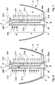
Figure 1 is a cross-section of the capsule according to the invention; -
Figure 2 is an enlarged detail of the capsule inFigure 1 ; -
Figure 2b is an enlarged detail of a version of the capsule inFigure 1 , in which a second duct comprises a solid product; -
Figure 2c is an enlarged detail of a different version of the capsule inFigure 1 , in which the second duct comprises interaction means for interacting with a final product B; -
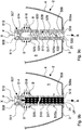
Figure 3 is a cross-section of a nozzle of the capsule inFigure 1 ; -
Figure 4 is a cross-section of the capsule inFigure 1 in an initial compressing and injecting step of a fluid; -
Figure 5 is a cross-section of the capsule inFigure 1 in a delivering step of a final product; -
Figures 6 to 10 are partial cross-sections of respective versions of the capsule of the invention; -
Figure 11 is a side view of the capsule of the invention, comprising a closing element provided with a tab; -
Figure 12 is a bottom view of the capsule inFigure 11 . - Herein below, the same elements will be indicated by the same numerals in the various Figures.
- With reference to the
Figures 1 to 5 and to theFigures 11 and 12 , acapsule 1 according to the invention is illustrated, containing an initial product P and usable in an automatic brewing machine to produce, by injection of a pressurized fluid therein, a final product B, for example, a beverage, such as coffee, barley, tea, etc. - The initial product P is, for example, a soluble, freeze-dried, dehydrated, concentrated, percolable, for infusion, food product.
- The
capsule 1 comprises anexternal casing 2, or container, substantially in the shape of a glass or a cup, provided with abase wall 3 and with aside wall 4, defining acavity 5 which is open and suitable to contain the initial product P from which the final product B can be obtained. - The
casing 2 is compressible and/or crushable and/or deformable, obtained by forming of a thermoformable material sheet, in particular a liquid- and gas-impermeable multilayered plastics and suitable for contact with foodstuffs. - To allow the
casing 2 to be compressed and crushed along a direction A almost parallel to a longitudinal axis of thecapsule 1 and substantially orthogonal to thebase wall 3, theside wall 4 is deformable and/or compressible along preset pliability lines 17, for example, having a helicoidal trend, or it is made in the shape of an accordion or of a bellows, as in the embodiment illustrated inFigure 12 . - Furthermore, the
side wall 4 is divergent starting from thebase wall 3 to a peripheral flange-shaped edge 6, for example, having an almost frusto-conical shape. - The
base wall 3 is, for example, concave in the direction of thecavity 5. - The
capsule 1 comprises anozzle 107 associated with thecasing 2 arranged to introduce a fluid F into thecavity 5, in particular a pressurized hot liquid, for example water, capable of interacting with the initial product P to obtain the final product B. - The
nozzle 107 comprises an elongated and rigid tubular member, having alongitudinal side wall 110, afirst end 108, and asecond end 109 mutually opposite. Thefirst end 108 is provided with afirst opening 113 arranged to engage with injecting means of a brewing machine capable of delivering the fluid F, while thelongitudinal side wall 110 is provided with at least one outflow opening 111 that is flowingly connected, via afirst duct 114, to thefirst opening 113 and it is arranged to introduce the fluid F into thecavity 5 in an injecting step J, as best described in the following description. - In a non-illustrated version of the
capsule 1, the nozzle is provided with a plurality ofoutflow openings 111 arranged to deliver into thecavity 5 respective fluid jets L. - The
second end 109 is provided with asecond opening 116 flowingly connected, via asecond duct 117, to a delivering opening 118 made on thelongitudinal side wall 110. The delivering opening 118, thesecond duct 117, and thesecond opening 116 allow the final product B to exit thecavity 5 and to be delivered directly into a fruition container in a delivering step E, as best described in the following description. - The
first duct 114 and thesecond duct 117 are placed side by side, in particular, they are parallel to one another and to a longitudinal axis X of thenozzle 107, and extend substantially over the entire length of the latter. In the illustrated embodiment, theoutflow opening 111 is made in the proximity of thesecond end 109, while the delivering opening 118 is made in the proximity of thefirst end 108. - With particular reference to
Figure 2 , in an initial configuration K of thecapsule 1, in which thecasing 2 is not compressed nor crushed, thenozzle 107 is arranged inside thecavity 5 with thesecond end 109 partially exiting the above-mentionedcavity 5 through anexit opening 31 made in thebase wall 3. Thenozzle 107 inserts and can slide with interference (thus making a hydraulic sealing) in the exit opening 31: in such a manner, as best explained in the following description, the final product B may exit thecapsule 1 only through thenozzle 107, and in particular through the delivering opening 118, thesecond duct 117, and thesecond opening 116. - The
second end 109 of thenozzle 107 has anexternal flange 109a peripherally surrounding thesecond opening 116. In an initial configuration K of thecapsule 1, theexternal flange 109a abuts against an external surface of thebase wall 3. - A
closing element 139 is provided to hermetically close thesecond opening 116 of thenozzle 107 and insulating from the external environment thecavity 5. Theclosing element 139, for example in the shape of a disc, comprises a joining, for example annular, edge, 139a by which it is removably fixed to an external surface of thebase wall 3. Theclosing element 139 may be easily detached from thebase wall 3 in an automatic manner by thenozzle 107 in an initial partial crushing step of thecasing 2, or again by the pressure of the air contained inside thecavity 5, which is in turn pushed to the outside by the introduction of the fluid F into the capsule during the injecting step J. - The
closing element 139 may be further easily detached from thebase wall 3 manually by a user before the insertion of thecapsule 1 into the brewing machine, and in this case it is provided, according to a preferred embodiment, with anelongated tab 139b extending outwardly starting from a connecting portion of the joiningedge 139a. - The
closing element 139, provided with or devoid of thetab 139b, is made of plastics, or aluminum, weldable, for example thermally or by ultrasounds, and the joiningedge 139a is, in particular, fixed to the external surface of thebase wall 3 by afirst portion 239a by a blocking seal and by asecond portion 239b by a peelable seal, the blocking seal requiring a greater force compared to the peelable seal to detach the joiningedge 139a from thebase wall 3, so as to promote the release of thesecond portion 239b of the joiningedge 139a before releasing thefirst portion 239a. - The
first portion 239a extends in a first angular interval comprised between 80° and 100°, in particular preferably 100°, and thesecond portion 239b extends in a second angular interval that is explementary to the first angular interval, in other words, thefirst portion 239a and thesecond portion 239b extend over the entire joiningedge 139a. - If the
closing element 139 is provided with theelongated tab 139b, the connecting portion of the joiningedge 139a extends from thefirst portion 239a fixed by the blocking seal, due to reasons that will be best seen herein below. - The
second portion 239b, fixed by a peelable seal, comprises detachment promoting means to promote a gradual and progressive separation of the joiningedge 139a from thebase wall 3, which comprise at least onedetachment portion 240, at which thesecond portion 239b has substantially a "V", or wedge, shape. - Preferably, the detachment promoting means comprises a plurality of
detachment portions 240 angularly equidistant in thesecond portion 239b, as shown inFigure 12 , to distribute the efficiency of such release along the entiresecond portion 239b. - On the contrary, the
first portion 239a fixed by the blocking seal is devoid of the detachment promoting means, and, therefore, although both the blocking seal and the peelable seal allow removably fixing theclosing element 139 to thebase wall 3, the blocking seal requires a greater force compared to the peelable seal to allow the release of thefirst portion 239a with respect to thesecond portion 239b. - If the
tab 139b is present, and only one detachment portion 240 (not illustrated) is present, the latter is located in thesecond portion 239b along a symmetry axis S of thetab 139b, on the opposite side with respect to thetab 139b. - In this manner, when the
closing element 139 is pushed by thenozzle 107 and detached in an automatic manner, thefirst portion 239a remains connected to thebase wall 3 and acts as a hinge element about which the portion of theclosing element 139 comprising thesecond portion 239a of the joiningedge 139a may rotate, away from thebase wall 3. According to a non-illustrated embodiment, theclosing element 139 may be removably fixed to theexternal flange 109a so as to hermetically close thesecond opening 116. In this case, the closing element has to be manually detached by the user before inserting thecapsule 1 into the brewing machine. - The
capsule 1 further comprises a coveringelement 19 that is fixed to theedge 6 of thecasing 2 to hermetically close thecavity 5. The coveringelement 19 is perforable, in particular by the injecting means of the brewing machine, to allow the injecting means to engage thefirst opening 113 of thenozzle 107 and introduce the fluid F into the capsule through thenozzle 107. - The covering
element 19 is fixed by means of a welding also to thefirst end 108 of thenozzle 107, collaborating with theexit opening 31 to keep the above-mentionednozzle 107 in place inside thecavity 5, and above all creating a fluid seal between the coveringelement 19 and the above-mentionedfirst end 108. In this manner, the fluid F received from thenozzle 107 in thefirst opening 113 is delivered to the containing cavity of the product P only through theoutflow opening 111 and undesired leaks of the fluid F at thefirst end 108 are avoided. - Both the
closing element 139 and the coveringelement 19 are made of selected materials, for example, multilayered plastic polylaminates, so as to protect over time from moisture and oxygen the initial product P contained in the capsule. Such multilayered plastics may for example contain aluminum or a different barrier layer, for example, ethylene vinyl alcohol (EVOH) or polyvinylidene chloride (PVDC). If they contain, for example, aluminum, they cannot be considered as recyclable plastics, therefore they have to be divided from the remaining plastics composing the capsule to the aims of waste disposal. - The operation or use of the
capsule 1 of the invention in an automatic brewing machine provides for an initial step of partial crushing of thecasing 2 to allow thenozzle 107, slidable with interference in theexit opening 31, further exiting the latter, at least partially detaching theclosing element 139. In fact, the portion of theclosing element 139 comprising thesecond portion 239b rotates away from thebase wall 3 about thefirst portion 239a, still connected to the base wall, acting as a hinge line of theclosing element 139. - The detachment, even if partial, of the
closing element 139 puts thecavity 5 flowingly connected with the external environment, through the deliveringopening 118, thesecond duct 117, and thesecond opening 116. In this manner, the air contained inside thecapsule 1 may freely exit when, in the successive injecting step J, the fluid F is introduced into thecavity 5 through theoutflow opening 111 of thenozzle 107. Thenozzle 107 exits thecapsule 1 by a reduced amount, so as to ensure that theoutflow opening 111 remains anyhow inside thecavity 5 to introduce the fluid F inside the latter (Figure 4 ). - The
nozzle 107 is supplied by injection means of the brewing machine capable of perforating the coveringelement 19 and engaging thefirst opening 113. - Alternatively, the
closing element 139 may be manually removed by the user before inserting thecapsule 1 into the brewing machine. In this case, thecasing 2 needs not to be partially compressed and crushed before and/or during the injecting step J of the fluid F. - In the injecting step J, the fluid F inserted through the
nozzle 107 may interact with the initial product P to gradually form the final product B. In this step, thecasing 2 of thecapsule 1 is partially crushed (to allow as illustrated above the nozzle detaching the closing element 139) and the second end 199 of thenozzle 107 is engaged, seal fit in theexit opening 31. Since the deliveringopening 118 is in the proximity of thefirst end 108 of thenozzle 107, the fluid F, the mixture of fluid and initial product P, and the final product B progressively forming on the bottom of thecapsule 1, cannot exit externally to the latter through thesecond opening 116. - The pressure and temperature of the fluid F introduced into the
cavity 5 have to be suitably adjusted as a function of the type and composition of the initial product P. - Once the
cavity 5 has been completely filled with the fluid F interacting with the initial product P to form the final product B, it is possible to deliver the latter in a delivering step E directly into a fruition container that is suitably arranged. - The delivering step may be implemented by progressively compressing and crushing the
casing 2 along the direction A so as to allow thenozzle 107 to further exit thecavity 5 through theexit opening 31, and above all so as to force the final product B to exit thecavity 5 through the deliveringopening 118, thesecond duct 117, and thesecond opening 116. Since thelongitudinal side wall 110 of thenozzle 107 abuts against with interference and then sealingly slides in theexit opening 31, and since thecavity 5 is closed, by crushing and compressing thecasing 2 the final product B contained therein is in fact forced by the pressure to enter the deliveringopening 118 and exit thecapsule 1 through thesecond duct 117 and thesecond opening 116. - When the
outflow opening 111 of thenozzle 107 is outside of thecapsule 1, during the progressive crushing of thecasing 2 and the consequent progressive exit of thenozzle 107, it is possible to further deliver directly into the fruition container also the fluid F. More precisely, thenozzle 107 allows delivering at the same time the fluid F (through thefirst duct 114 and the outflow opening 111) and the final product B (through thesecond duct 117 and the second opening 116) so as to further dilute the latter and to make a desired dose of final product. Such operation, which with the known capsules has to be implemented manually by the user, may be instead carried out in an automatic manner by the brewing machine using thecapsule 1 of the invention. - It shall be noticed that the
capsule 1 of the invention allows delivering into the container only the final product B (during the delivering step E) at the end of the solubilization and/or dissolution thereof. In fact, the configuration of thenozzle 107 prevents also the accidental exit of the fluid F from thecapsule 1 during the preparation step of the final product B. - Alternatively, the delivering step E may be initially carried out by continuing to inject the fluid F into the
cavity 5, thus forcing the final product B to exit due to the action of the pressure from thecapsule 1. Subsequently, by completely compressing and crushing thecasing 2, the complete outflow of the final product B from the capsule is made. - It shall be noticed that also with such delivering mode, it is possible to dilute the final product B and make a desired final amount thereof that is greater than the capsule capacity. Such operation, which with the known capsules has to be carried out manually by the user, may be instead carried out in an automatic manner by the brewing machine using the
capsule 1 of the invention. - At the end of the delivering operation, a user may manually complete the removal of the covering element 19 (and to such aim, in a non-illustrated embodiment, the covering element could also be provided with an elongated tab) and/or of the
closing element 139, in order to separate components in recyclable plastics, as surely thecasing 2 and thenozzle 107 are, from non-recyclable components, as could be the coveringelement 19 and/or theclosing element 139 if they are made in a multilayered plastics containing for example aluminium. - As regards the
closing element 139, the user may separate it from thecapsule 1 by grasping the portion already detached of theclosing element 139 comprising thesecond part 239b or the user may advantageously, if present, grasp thetab 139b connected to thefirst part 239a of the joiningedge 139 thus avoiding getting contaminated and/or wetted in case the above-mentioned already detached portion contacted during the delivering operation the final product B. - Therefore, it is possible to define a method to produce a final product B using the
capsule 1 of the invention in an automatic brewing machine, comprising the following steps: - introducing, in an injecting step J the fluid F inside a
cavity 5 of thecapsule 1 through thefirst opening 113, thefirst duct 114 theoutflow opening 111 of thenozzle 107 so that the fluid F interacts with the initial product P contained in saidcapsule 1; - delivering the final product B so obtained directly into a fruition container in a delivering step E through at least the delivering
opening 118, thesecond duct 117 and thesecond opening 116 of thenozzle 107, said delivering comprising continuing to introduce the fluid F in thecavity 5 and/or progressively compressing and crushing thecasing 2 of thecapsule 1 so as to force the final product B to exit by pressure from thecavity 5 through the deliveringopening 118, thesecond duct 117 and thesecond opening 116. - Before introducing the fluid F, it is further provided to remove the
closing element 139 fixed to thehermetic seal capsule 1 of thesecond opening 116 of thenozzle 107, said removal comprising partially compressing and/or crushing thecasing 2 so as to force thenozzle 107 to further exit thecavity 5 and at least partially detaching theclosing element 139. - It is worth noting that the
capsule 1 of the invention allows delivering the final product B directly in a fruition container without the need of performing the perforation of thebase wall 3. Thenozzle 107 exiting thecavity 5 through the exit opening 31 of thebase wall 3 allows the controlled exit of the final product B through the deliveringopening 118, thesecond duct 117 and the second opening 16 directly into the fruition container during the delivering step. - Therefore, the
capsule 1 of the invention may be used in a brewing machine not provided with a delivering circuit, since such capsule does not require extracting means suitable to perforate the bottom of the capsule to allow the exit of the final product, nor duct means to convey such final product into the fruition container (for example, a mug, a cup, a glass, etc.). - The absence of the delivering circuit makes the brewing machine simpler and more inexpensive, and it further ensures the hygiene of the delivering process and the maintenance of the quality of the delivered beverages, since contaminations between beverages delivered at later moments are not possible.
- Another advantage of the
capsule 1 of the invention is that it prevents that the injecting means of the brewing machine contacts the initial product P and/or the mixture/final product B in the preparation step and, subsequently, in the delivering step. In fact, thenozzle 107 of thecapsule 1 is arranged to be engaged, by thefirst opening 113 of thefirst end 108, by the injecting means of the brewing machine. In such a manner, also by virtue of the coveringelement 19 welded to thenozzle 107 at thefirst end 108, the injecting means, also when they are inserted in, and engaged to, saidfirst opening 113 are separated and insulated from thecavity 5 and the initial product P. Thus the supply circuit of the machine, comprising the injecting means, is not contaminated or polluted by the initial and/or final product, this ensuring the hygiene of the delivering process and the quality of the final products at each delivering operation. - A further advantage of the
capsule 1 is that it does not require a special sealed package, since the coveringelement 19 and theclosing element 139 hermetically insulate thecavity 5 from the external environment so as to preserve the initial product P. -
Figure 6 illustrates a version of thecapsule 1, differing from the embodiment described above and referred to in theFigures 1 to 5 , since it comprises arespective nozzle 207, having a shape similar to thenozzle 107, having a respectivelongitudinal side wall 210, a respectivefirst end 208, and a respectivesecond end 209 mutually opposite. Thenozzle 207 comprises a plurality ofrespective outflow openings 211 made mutually spaced apart along thelongitudinal side wall 210 substantially over the entire length of the latter and connected by a respectivefirst duct 214 to a respectivefirst opening 213 with which thefirst end 208 is provided. Thenozzle 207 also includes a plurality of respective deliveringopenings 218 made mutually spaced apart along saidlongitudinal side wall 210 substantially over the entire length of the latter and connected by a respectivesecond duct 217 to a respectivesecond opening 216 with which thesecond end 209 is provided. Theoutflow openings 211 and the deliveringopenings 218 are substantially opposite. Thenozzle 207 comprises a respectiveexternal flange 209a, similar to theexternal flange 109a inFigure 3 . - Such capsule is in particular suitable for use with an initial product P to be percolated, typically coffee powder. In fact, the
outflow openings 211 allow the fluid F percolating in a substantially even and complete manner through the mass of initial product contained in thecavity 5. The deliveringopenings 218, suitably sized, allow the exit of the final product B (percolate), holding and preventing the exit of the initial product P. - The operation or use of this version of
capsule 1 of the invention in an automatic brewing machine provides for an initial step of partial crushing of the casing 2 (represented inFigure 6 in dotted line) to allow thenozzle 207 at least partially detaching the closing element 139 (thus connecting thecavity 5 to the external environment through the deliveringopenings 218, thesecond duct 214, and the second opening 216) and above all for compressing and compacting the initial product P inside thecapsule 1. The extent of the crushing of thecasing 2 is calculated to ensure a compaction of the initial product P that prevents the formation of preferential passage pathways of the fluid F during the percolation so as to make a final beverage B (coffee) with a high quality and satisfactory organoleptic characteristics. It is also possible to use a compressible andcrushable casing 2 obtainable in thermoformable plastics with a reduced cost. - The injecting step and the delivering step in this case coincide, since while the fluid F is injected and exits into the
cavity 5 through theoutflow openings 211, the final product B made from the percolation exits the cavity through the deliveringopenings 218. It shall be noticed that thenozzle 207 acts as a filter, allowing the exit of the final product B directly delivered into the fruition container and holding inside the capsule the percolated initial product. - A method to produce the final product B by using, in an automatic brewing machine, the version of capsule described above, comprises the steps of:
- compressing and crushing the
casing 2 to compress and compact an initial product P to be percolated, in particular coffee powder contained in the capsule; - inserting, in an injecting step J, the fluid F inside the
cavity 5 of thecapsule 1 through thefirst opening 213, thefirst duct 214, and theoutflow openings 211 of thenozzle 207 so as to make, in particular by percolation, the fluid F to interact with the initial product P and make the final product B; - delivering the final product B directly in a fruition container in a delivering step E through the delivering
openings 218, thesecond duct 217, and thesecond opening 216 of thenozzle 207, said delivering comprising continuing to inject the fluid F into thecavity 5 so as to force the final product B to exit by pressure from thecavity 5 through the deliveringopening 218, thesecond duct 217, and thesecond opening 216. -
Figure 7 illustrates a version of thecapsule 1 differing from the capsule inFigure 6 since it comprises arespective nozzle 307, similar to thenozzle 207 inFigure 6 , having a respectivelongitudinal side wall 310, a respectivefirst end 308, and a respectivesecond end 309 mutually opposite. - The
nozzle 307 comprises a respectiveexternal flange 309a, similar to theexternal flange 109a inFigure 3 . - The
nozzle 307 comprises a plurality ofrespective outflow openings 311 made mutually spaced apart along thelongitudinal side wall 310 substantially over the entire length of the latter, and a plurality of respective deliveringopenings 318 made mutually spaced apart along saidlongitudinal side wall 310, but arranged only in the proximity of thefirst end 308 at a preset distance H from thebase wall 3 of thecasing 2, unlike what has been described for thenozzle 207. Thenozzle 307 comprises a respectiveexternal flange 309a, similar to theexternal flange 109a inFigure 3 . - Such capsule is in particular suitable for use with an initial product P for infusion. The delivering
openings 318, suitably sized, allow the exit of the final product B, holding and preventing the exit of the initial product P (e.g. tea leaves) only when thecasing 2 is compressed and crushed, allowing a pre-infusion step of the initial product comprised between the injecting step of the fluid and the delivering step. More precisely, the operation or use of this version ofcapsule 1 of the invention in an automatic brewing machine provides for: - an initial step of partial crushing of the
casing 2 to allow thenozzle 307 at least partially detaching theclosing element 139 and thus connecting thecavity 5 with the external environment; - an injecting step J in which a fluid F is introduced into the
cavity 5 through theoutflow openings 311 until reaching a level H below the height of the deliveringopenings 318; - a pre-infusion step with a variable duration as a function of the initial product P that allows making by infusion the final product (tea);
- a delivering step in which the
casing 2 is compressed and crushed to allow the exit of the final product B from thecapsule 1 through the deliveringopenings 311, thesecond duct 317, and thesecond opening 316 of thenozzle 307, directly into the fruition container. - After the pre-infusion step, and before the delivering step, it is possible to inject further fluid F into the
cavity 5 through theoutflow openings 311. This allows diluting the final product B before the crushing of thecasing 2 and making a final desired amount thereof greater than the capacity of thecapsule 1. Such operation, that with the known capsules has to be performed manually by the user, may be instead performed in an automatic manner by the brewing machine using thecapsule 1 of the invention. -
Figure 8 illustrates another version of thecapsule 1 differing from the illustrated embodiment in theFigures 1 to 5 , since it comprises arespective nozzle 407, having a respectivelongitudinal side wall 410, a respectivefirst end 408, and a respectivesecond end 409 mutually opposite. Thenozzle 407 comprises a pair of respectiveopposite outflow openings 411, in particular substantially aligned, and made on thelongitudinal side wall 410 at thefirst end 408, and a pair of respective opposite deliveringopenings 418, in particular substantially aligned, and made on thelongitudinal side wall 410 adjacent to theoutflow openings 411, interposed between the latter ones and thesecond end 409 at a preset distance from thebase wall 3 of thecasing 2. Theoutflow openings 411 are flowingly connected with a respectivefirst opening 413 with which thefirst end 408 is provided by a respectivefirst duct 414, while the deliveringopenings 418 are flowingly connected with a respectivesecond opening 416 with which thesecond end 409 is provided by a respectivesecond duct 417. In this version, thefirst duct 414 and thesecond duct 417 are superimposed and substantially aligned to the longitudinal axis X of thenozzle 407. Thenozzle 407 comprises a respectiveexternal flange 409a, similar to theexternal flange 109a inFigure 3 . - The
nozzle 407 further comprises a respectiveannular projection 425, arranged adjacent to the deliveringopenings 418, between the latter ones and thesecond end 409. Theannular projection 425 radially projects from thelongitudinal side wall 410 and it is arranged to abut against thebase wall 3 and prevent the complete crushing of thecasing 2 so as to keep theoutflow openings 411 and the deliveringopenings 418 inside thecapsule 1 throughout the delivering step. - The
annular projection 425 acts as a stroke stop when crushing of thecasing 2 and prevents the complete exit of thenozzle 407 from thecapsule 1. The tests performed showed that this capsule is particularly versatile, since it is suitable for use with a soluble initial product P, for example a soluble powder, or with a concentrated liquid, or with an initial product P for infusion. - The
annular projection 425 could be advantageously applied also to the versions of thecapsule 1 of the invention illustrated in the remaining Figures, and not only to the version inFigure 8 . - The operation or use of this version of
capsule 1 of the invention in an automatic brewing machine provides for an initial step of partial crushing of thecasing 2 to allow thenozzle 407, and in particular theexternal flange 409a, at least partially detaching theclosing element 139 and thus connecting thecavity 5 with the external environment, through the deliveringopening 418, thesecond duct 417, and thesecond opening 416. - In the injecting step J, the fluid F is introduced into the
cavity 5 through theoutflow openings 411 so as to interact with the initial product P. In an initial mixing step of the fluid F with the initial product P, the distance of the deliveringopenings 418 from thebase wall 3 prevents the exit of not perfectly solubilized and/or diluted and/or infused fluid and product. The delivering step starts when the already solubilized, diluted and/or infused final product B reaches the height of the deliveringopenings 418. In the case where a product for infusion is present, a pre-infusion step or pause may be provided for, with a variable duration as a function of the initial product P that allows making by infusion the final product (tea). - At this point, the
casing 2 may be compressed and crushed to allow the exit of the final product B. - By virtue of the configuration of the
nozzle 407, also during the crushing of the casing 2 (and at the end of the crushing by virtue of the annular projection 425), it is possible to continue introducing fluid F inside thecavity 5 through theinflow openings 411 so as to continue to solubilize and/or dilute the initial product P. Theannular projection 425, acting as a stroke stop for the crushing of thecasing 2, ensures that the delivering, i.e., the exit of the final product B from thecapsule 1, always occurs through thesecond opening 416 of thenozzle 407. -
Figure 9 illustrates a further version of thecapsule 1 differing from the capsule inFigure 8 in that it comprises arespective nozzle 507, similar to thenozzle 407 inFigure 8 , having a respectivelongitudinal side wall 510, a respectivefirst end 508, and a respectivesecond end 509 mutually opposite. Thenozzle 507 comprises a pair ofrespective outflow openings 511 arranged opposite at thefirst end 508 of thenozzle 507 and inclined, for example by an angle ranging between 20° and 45° and preferably 30° with respect to thelongitudinal side wall 510, so as to direct respective jets of fluid F towards thebase wall 3. Thenozzle 507 further comprises a plurality of respective deliveringopenings 518 made mutually spaced apart and opposite along thelongitudinal side wall 510 for a limited length and interposed between theoutflow openings 511 and thebase wall 3. Theoutflow openings 511 are flowingly connected with a respectivefirst opening 513 by afirst duct 514, while the deliveringopenings 518 are flowingly connected with a respectivesecond opening 516 by asecond duct 517. Thefirst duct 514 and thesecond duct 517 are superimposed and substantially aligned to the longitudinal axis X of thenozzle 507. Thenozzle 507 comprises a respectiveexternal flange 509a, similar to theexternal flange 109a inFigure 3 . - In a similar manner to what has been stated for the
annular projection 425 of thenozzle 407, thenozzle 507 comprises a respectiveannular projection 525, arranged adjacent to the deliveringopenings 518, between the latter ones and thesecond end 509, acting as a stroke stop when crushing of thecasing 2 and prevents the complete exit of thenozzle 507 of thecapsule 1. - It is further provided a further
annular projection 525a that also projects from thelongitudinal side wall 510 configured to act as an intermediate stroke stop in the initial step of partial crushing of thecasing 2 along the direction A. In particular, the furtherannular projection 525a is near to theexternal flange 509a. In particular, the furtherannular projection 525a is located at a distance from the external flange, measured parallel to the crushing direction A such as to allow, in such initial crushing step of thecasing 2, the at least partial detachment of theclosing element 139 from thebase wall 3 of thecasing 2 by theexternal flange 509a. More precisely, the distance from theexternal flange 509a at which the furtherannular projection 525a is located is sufficient to allow thenozzle 507 at least partially detaching theclosing element 139 from thebase wall 3 of thecasing 2, while maintaining theclosing element 139 in a preset position during a pause step having a variable duration, such as, for example the mixing and/or pre-infusion, such position being such as not to hinder the successive exit of the final product B. - The further
annular projection 525a is of such dimensions as not to prevent the further exit of thenozzle 507 from the capsule to the stroke stopannular projection 525, in a successive compression and crushing step of thecasing 2. - Such further
annular projection 525a could be advantageously also applied to the versions of thecapsule 1 of the invention illustrated in the remaining figures, and not only to the version inFigure 9 . - The operation or use of this version of
capsule 1 is substantially similar to that of the capsule inFigure 8 . Theinclined outflow openings 511 allow better directing the fluid F against the initial product P laying on thebase wall 3 so as to move it, mix, more easily dissolve, or extracting the aromatic characteristics of the products for infusion. The delivering of the final product B is promoted by the number of deliveringopenings 518. The tests performed showed that this version of capsule is in particular versatile and is indicated for initial products comprising soluble powders, freeze-dried products, liquid concentrates or with an initial product P for infusion. -
Figure 9b illustrates a further version of thecapsule 1 differing from the capsule inFigure 9 in that it comprises a solid product UP, schematically illustrated, contained in thesecond duct 517 and deliverable directly into a fruition container through thesecond opening 516 before the delivering step E. - The solid product UP may be soluble or not soluble, and it is intended to be consumed together with the final product B.
- The solid product UP may be composed of only one element (for example, a cookie, or a crouton or a piece of bread), or by a plurality of elements, such element(s) having at least one dimension (length, width, or height) that is greater than, or the same as, a width of the delivering
opening 518, so that the deliveringopening 518 prevents such solid product UP exiting thesecond duct 517 towards thecavity 5. In such a manner, the solid product UP remains inside thesecond duct 517 separated from the initial product P all the time that thecapsule 1 remains unused. - In particular, the solid product UP may comprise multiple elements that are homogenous to each other, i.e., of the same type, such as, for example sweeteners, or cereals, colored or not, or croutons, and the like, or a plurality of elements that are mutually non-homogenous, for example, a mixture of sweeteners and cereals.
- The solid product UP may be inserted into the
capsule 1 in the production line, this reducing and simplifying a product storehouse. This further allows diversifying, in a packaging step,capsules 1 containing a same initial product P. In fact, in the packaging step it is possible to add to thecapsules 1 containing a same initial product P, a plurality of different solid products UP. For example, it is possible to add to thecapsule 1 containing a same product P, a solid product UP composed of a sweetener, or a solid product UP composed of cereals. - The operation or use of this version of
capsule 1 in an automatic brewing machine is substantially similar to that of the capsule inFigure 9 as regards the preparation of the final product B. In addition, the capsule inFigure 9b allows using the solid product UP. - The solid product UP may be delivered directly into the fruition container in an automatic manner. According to such manner, the step of partial crushing of the
casing 2 allows thenozzle 507 at least partially detaching theclosing element 139, so as to connect thesecond duct 517 to the external environment via thesecond opening 516, and allow the exit of the solid product UP from thesecond duct 517 towards the fruition container. - Alternatively, the solid product UP may be delivered directly into the fruition container in a manual manner. According to such manner, the
closing element 139 is manually detached from thebase wall 3 by a user before inserting thecapsule 1 into the brewing machine. The user, at discretion, may determine the amount of solid product UP to be delivered into the fruition container, for example, in the case that the solid product UP is a sweetener, to obtain a sweeter or less sweet final product B. Of course, in a manual manner, the user may also decide not to use the solid product UP at all. In this case, the user has only to remove the solid product UP from thesecond duct 517 without inserting it into the fruition container. - It is added that the solid product UP could be advantageously provided, inside the respective second ducts, also in the versions of the
capsule 1 of the invention illustrated in the remaining Figures, and not only in the version inFigure 9b . -
Figure 2b shows for example a different version of thecapsule 1, differing from the capsule inFigure 1 in that it comprises the solid product UP contained in thesecond duct 117. The version inFigure 2b is not described herein, to the same elements already described above corresponding to the same numeral references. -
Figure 9c illustrates a further version of thecapsule 1 differing from the capsule inFigure 9 in that it comprises interaction means for interacting with the final product B contained in thesecond duct 517, to vary organoleptic or visual characteristics of such final product B before the delivering into the fruition container. - Such interaction means comprise a vortex flow generating member and/or a perforated member (not illustrated), the latter to perform a filtering function or, alternatively, to reduce or eliminate possible froth present in the final product B.
- The vortex flow generating member comprises an elongated and rigid tubular-shaped
insert 528 having alongitudinal side wall 529 provided with ahelicoidal projection 530 extending longitudinally at least along a portion of saidinsert 528, preferably along theentire insert 528. Theinsert 528 is contained in thesecond duct 517 and creates anannular gap 531, between asmooth wall 532 of thesecond duct 517 and saidside wall 529 provided with theprojection 530. Theannular gap 531 has channels with a helicoidal trend, to generate the vortex flow of fluid into the annular gap. In this manner, the final product B, before being delivered into the fruition container, is rotated and forced to flow with a vortex motion into theannular gap 531. The final product B is further mixed, thus the complete and homogeneous solubilization of products not much or slowly soluble is further promoted. The vortex motion may, in addition or alternatively, promote the formation of froth in the final product B, if desired. Theinsert 528 further comprisesend projections 533 allowing holding thesame insert 528 in place inside thesecond duct 517 by interference. Between aprojection 533 and the other one, delivering passages of the final product B are defined. - The
projection 530 illustrated inFigure 9b has a longitudinal extent such as to be in the shape of a band, with coils tilted by 30° with respect to a longitudinal axis of theinsert 528. Theprojection 530 may be also made in the shape of a thread (not shown). The pitch of the coils, the longitudinal extent of each coil, which dictates whether the projection is in the form of a band or a thread, and the thickness of theprojection 530 in the perpendicular direction to the longitudinal axis of theinsert 528 determine the rotation in the fluid and therefore they are selected based on the type of final product B to be obtained. - The perforated member may be for example obtained as an insert in the shape of a micro-perforated disc, or as a hollow tubular insert with opposite micro-perforated head walls, arranged in the
second duct 517 and held in place by interference, to perform a filtering function and avoiding the exit of fragments of the initial product P into the fruition container that are possibly present in the final product B. - Alternatively, the perforated member may comprise an insert provided with a large mesh net to reduce or avoid a possible froth present in the final product B when the froth is not required for the particular final product B to be delivered.
- The vortex flow generating member and the perforated member may be present alternatively in the second duct 17.
- However, the vortex flow generating member and the perforated member may be present also at the same time in the
second duct 517, if, for example, the final product B requires a further mixing to promote a complete solubilization of the initial product P, while the reduction of the possible froth created by the vortex flow before the delivering into the fruition container is desired. - Such interaction means are inserted in the
second duct 517 in the production line, this reducing and simplifying a product storehouse. - The operation or use of this version of
capsule 1 in an automatic brewing machine is substantially similar to that inFigure 9 and to that of the versions illustrated in the remaining Figures, but, in addition, the final product B is further mixed and/or filtered and/or froth in it is created/avoided. Therefore, some qualitative characteristics of the final product B are changed in a simple and efficient manner, without the need for modifying the type of capsule to be produced. - The interaction means for interacting with the final product B, although described with particular reference to the
Figure 9c , could be advantageously provided inside the respective second ducts, also in the versions of thecapsule 1 of the invention illustrated in the remaining figure. -
Figure 2c shows, for example, a different version of thecapsule 1, differing from the capsule inFigure 1 in that it comprises interaction means for interacting with the final product B contained in thesecond duct 117, and i.e. thecapsule 1 comprises thetubular insert 528. The version inFigure 2c is not described herein, to the same elements already described above corresponding the same numeral references. -
Figure 10 illustrates a further version of thecapsule 1 differing from the capsule inFigure 8 since it comprises arespective nozzle 607, similar to thenozzle 407 described above, having a respectivelongitudinal side wall 610, a respectivefirst end 608, and a respectivesecond end 609 mutually opposite. - The
nozzle 607 comprises a respectiveexternal flange 609a, similar to theexternal flange 109a inFigure 3 . - The
nozzle 607 comprises arespective outflow opening 611 and a respective deliveringopening 618 arranged substantially opposite to thefirst end 608, substantially aligned and orthogonal to thelongitudinal side wall 610. Theoutflow opening 611 is flowingly connected with a respectivefirst opening 613 with which thefirst end 608 is provided by a respectivefirst duct 614, while the deliveringopening 618 is flowingly connected with a respectivesecond opening 616 with which thesecond end 609 is provided by a respectivesecond duct 617. Thefirst duct 614 and thesecond duct 617 are superimposed and substantially aligned to the longitudinal axis X of thenozzle 607. Thenozzle 607 comprises a respectiveannular projection 625, similar to theannular projection 425 described with reference toFigure 8 . - The operation or use of this version of
capsule 1 is substantially similar to that of the capsule inFigure 8 . - The tests performed showed that such version of capsule is in particular indicated for initial products comprising liquid concentrates.
- In a non-illustrated version of the
capsule 1 and with particular reference to theFigures 1 to 5 , theexternal flange 109a of thenozzle 107 has an external surface which is provided with an annular groove with a triangular cross-section near to thesecond opening 116 which is suitable to direct the final product B when it exits thecapsule 1 through the above-mentionedsecond opening 116. Such groove may aid in more accurately directing the final product B flow into the fruition container. Advantageously, such annular groove may be implementable also in the external flange of the nozzles shown in the versions of thecapsule 1 of the invention, illustrated in the remaining Figures. - In a further non-illustrated version of the capsule and with reference to the
Figures 1 to 5 , thebase wall 3 may comprise an edge or annular wall extending about theexit opening 31 and inside or outside thecavity 5. The annular wall is intended to sealingly engage thelongitudinal side wall 110 of thenozzle 107. The cross-sections of thenozzle 107 and annular wall are of a complementary shape. - Such version of the
base wall 3 may be advantageously applied also to the versions of thecapsule 1 of the invention illustrated in the remaining Figures. - It is further pointed out that all what has been stated regarding the
closing element 139 shown in theFigures 11 and 12 and provided for insulating thecavity 5 against the external environment, described above with particular reference to thenozzle 107 of thecapsule 1 of theFigures 1-5 may be advantageously applied also to the versions of thecapsule 1 illustrated in the remaining figures. - Again, it has been stated above that the covering
element 19 is fixed by welding to thenozzle 107 to create a fluid seal between the coveringelement 19 and thefirst end 108 of thenozzle 107. - Again, what has been described above with particular reference to the
nozzle 107 of thecapsule 1 of theFigures 1-5 may be advantageously applied also to the versions of thecapsule 1 illustrated in the remaining Figures, with particular reference also to thenozzles element 19. According to a further non-illustrated version, the initial product P is contained in a nonwoven fabric bag, when the exit of fragments of the initial product P into the fruition container is note desired. Advantageously, the initial product P, for example a product for infusion, may be contained in a bag, for example, in the shape of a sachet, similar to those for tea consumption. However, the bag may also be of a different shape, and for example provided with a hole, for example in the shape of a doughnut, so as to house the nozzle in such hole and to ensure the positioning of the bag inside the capsule about the nozzle. Whichever the shape of such bag, the capsule may contain multiple bags containing products of a different type and/or differently flavored, to obtain a two-flavored final product B, as an nut-flavored Americano coffee or a mint-flavored tea.
Claims (17)
- Capsule, comprising:- a casing (2) provided with a base wall (3) and a side wall (4) defining a cavity (5) suitable for containing an initial product (P) to be joined to a fluid (F) for making a final product (B), wherein said casing (2) comprises an edge (6);- a nozzle (107; 207; 307; 407; 507; 607) associated with said casing (2) and comprising a longitudinal side wall (110; 210; 310; 410; 510; 610) and a first end (108; 208; 308; 408; 508; 608) provided with a first opening (113; 213; 313; 413; 513; 613) suitable to engage injecting means of said fluid (F) of a brewing machine, said longitudinal side wall (110; 210; 310; 410; 510; 610) being provided with at least one outflow opening (111; 211; 311; 411; 511; 611) connected to said first opening (113; 213; 313; 413; 513; 613) through a first duct (114; 214; 314; 414; 514; 614) for introducing said fluid (F) in said cavity (5) in an injecting step (J);said capsule being characterized in that- said nozzle (107; 207; 307; 407; 507; 607) is arranged inside said cavity (5), comprises at least one delivering opening (118; 218; 318; 418; 518; 618) made along said longitudinal side wall (110; 210; 310; 410; 510; 610) and a second end (109; 209; 309; 409; 509; 609) that is opposite to said first end (108; 208; 308; 408; 508; 608), comes out partially from said cavity (5) through an exit opening (31) of said base wall (3) and is provided with a second opening (116; 216; 316; 416; 516; 616) connected to said delivering opening (118; 218; 318; 418; 518; 618) through a second duct (117; 217; 317; 417; 517; 617);- said delivering opening (118; 218; 318; 418; 518; 618) and said second duct (117; 217; 317; 417; 517; 617) enable said final product (B) to exit from said cavity (5) through said second opening (116; 216; 316; 416; 516; 616) and to be delivered directly into a fruition container in a delivering step (E).
- Capsule according to claim 1, comprising a closing element (139) removably fixed to a peripheral edge (109a) of said second end (109) and/or to an external surface of said base wall (3) so as to hermetically close at least said second opening (116) and said cavity (5).
- Capsule according to claim 2, wherein said closing element (139) comprises a joining edge (139a), said joining edge (139a) being fixed for a first part (239a) to said external surface of said base wall (3) by a blocking seal and for a second part (239b) by a peelable seal, said blocking seal requiring greater force than said peelable seal to detach said joining seal (139a) from said base wall (3), so as to promote said detachment of said second part (239b) before said detachment of first part (239a).
- Capsule according to claim 3, wherein said first part (239a) extends in a first angular interval comprised between 80° and 110°, in particular preferably 100°, and said second part (239b) extends in a second angular interval that is explementary to said first angular interval, said first part (239a) and said second part (239b) extending over the entire joining edge (139a).
- Capsule according to claim 3 or 4, wherein said second part (239b) comprises detachment promoting means comprising at least one detachment portion (240) at which said second portion (239b) has a substantially "V" or wedge shape to facilitate a gradual and progressive separation of the joining edge (139a) from the base wall (3).
- Capsule according to claim 5, wherein said first part (239a) is devoid of said detachment promoting means.
- Capsule according to claim 5, wherein said detachment promoting means comprises a plurality of detachment portions (240) that are angularly equidistant in said second part (239b).
- Capsule according to any one of claims 3 to 7, wherein said closing element (139) comprises an elongated tab (39b) extending outwards from a connecting portion of the joining edge (139a) that extends from said first part (239a).
- Capsule according to any one of claims 1 to 8, wherein said nozzle (107; 207; 307; 407; 507; 607) comprises a rigid and elongated tubular element, in particular made of plastics and wherein said first duct (114; 214; 314) and said second duct (117; 217; 317) are positioned side by side and extend substantially over the entire length of said nozzle (107; 207; 307), in particular parallel to a longitudinal axis (X) of said nozzle (107; 207; 307); or wherein said first duct (114; 214; 314) and said second duct (117; 217; 317) are superimposed and substantially aligned to a longitudinal axis (X) of said nozzle (107; 207; 307).
- Capsule according to any one of claims 1 to 9, wherein said outflow opening (111; 211; 311) is made in the proximity of said second end (109; 209; 309) and said delivering opening (118; 218; 318) is made in the proximity of said first end (108; 208; 308); or wherein said outflow opening (411; 511; 611) and said delivering opening (418; 518; 618) are made in the proximity of said first end (408; 508; 608); or wherein said capsule comprises a plurality of outflow openings (211; 311) that are made spaced apart from each other along said longitudinal side wall (210; 310) and connected to said first opening (213; 313) through said first duct (214; 314), and a plurality of delivering openings (218; 318) that are made spaced apart from each other along said longitudinal side wall (210; 310) and connected to said second opening (216; 316) through said second duct (217; 317)
- Capsule according to any one of claims 1 to 10, wherein said nozzle (107; 207; 307; 407; 507; 607) is inserted and sealingly slides with interference in said exit opening (31) and/or wherein said nozzle (407; 507; 607) comprises an annular projection (425; 525; 625) that is positioned adjacent to said delivering opening (418; 518; 618) and is arranged for preventing a complete exit of said nozzle (407; 507; 607) from said capsule (1).
- Capsule according to any one of claims 1 to 11, comprising a covering element (19) fixed to said edge (6) to hermetically close said cavity (5), wherein said covering element (19) is perforable by said injecting means of the brewing machine for enabling said injecting means to engage said first opening (113; 213; 313; 413; 513; 613) of said nozzle (107; 207; 307; 407; 507; 607) and wherein said covering element (19) is fixed by welding to said first end (108; 408) of said nozzle (107; 407) for creating a fluid seal between said covering element (19) and said first end (108; 408).
- Capsule according to any one of claims 2 to 12, and further comprising a solid product (UP) contained in said second duct (117; 217; 317; 417; 517; 617) closed by said closing element (139) and deliverable directly into said fruition container through said second opening (116; 216; 316; 416; 516; 616) before said delivering step (E); wherein said solid product (UP) is constituted of a single element having at least one dimension that is greater than, or the same as, a width of said delivering opening (118; 218; 318; 418; 518; 618) in such a manner that said delivering opening (118; 218; 318; 418; 518; 618) prevents said solid product (UP) from exiting said second duct (117; 217; 317; 417; 517; 617) towards said cavity (5); or wherein said solid product (UP) is constituted of a plurality of elements each having at least one dimension that is greater than, or the same as, a width of said delivering opening (118; 218; 318; 418; 518; 618) in such a manner that said delivering opening (118; 218; 318; 418; 518; 618) prevents said solid product (UP) from exiting said second duct (117; 217; 317; 417; 517; 617) towards said cavity (5) and wherein said elements are homogeneous elements, as for example sweeteners or cereals, or wherein said elements are non-homogeneous elements, as for example a mixture of sweeteners and cereals.
- Capsule according to any one of claims 1 to 13, and comprising interaction means for interacting with said final product (B) which is contained in said second duct (117; 217; 317; 417; 517; 617) for changing characteristics of said final product (B) before delivering into said fruition container, wherein said interaction means comprises an element for creating a vortex flow and/or a perforated element for making a filtering function or alternatively for reducing or eliminating possible froth present in the final product (B); and wherein said element for creating a vortex flow comprises an elongated tubular shaped insert (528) having a longitudinal side wall (529) provided with a helicoidal projection (530) extending longitudinally at least along a portion of said insert (528), preferably over the entire insert (528); and wherein said capsule (1) has an annular gap (531) between a smooth wall (532) of said second duct (117; 217; 317; 417; 517; 617) and said side wall (529) of said insert (528) provided with said projection (530), said annular gap (531) having helicoidal channels for creating said vortex flow.
- Capsule according to any one of claims 1 to 14, wherein said second end (109; 209; 309; 409; 509; 609) of said nozzle (107; 207; 307; 407; 507; 607) has an external flange (109a; 209a; 309a; 409a; 509a; 609a) which peripherally surrounds said second opening (116; 216; 316; 416; 516; 616) and which in an initial configuration (K) of said capsule (1), abuts against an external surface of said base wall (3).
- Method for making a final product (B) using in an automatic brewing machine a capsule (1) according to any one of claims 1 to 15, comprising the steps of:- introducing, in an injecting step (J), a fluid (F) inside a cavity (5) of said capsule (1) through a first opening (113; 213; 313; 413; 513; 613), a first duct (114; 214; 314; 414; 514; 614) and at least one outflow opening (111; 211; 311; 411; 511; 611) of a nozzle (107; 207; 307; 407; 507; 607) of said capsule (1) so that said fluid (F) and an initial product (P) contained in said cavity (5) interact for making a final product (B);- delivering said final product (B) directly into a fruition container in a delivering step (E) through at least one delivering opening (118; 218; 318; 418; 518; 618), a second duct (117; 217; 317; 417; 517; 617) and a second opening (116; 216; 316; 416; 516; 616) of said nozzle (107; 207; 307; 407; 507; 607), said delivering comprising continuing to introduce said fluid (F) in said cavity (5) so as to force said final product (B) to exit by pressure from said cavity (5) through said delivering opening (118), second duct (117; 317; 417; 517; 617) and second opening (116; 316; 416; 516; 616).
- Method according to claim 16, comprising, before said introducing said fluid, removing a closing element (139) fixed to said capsule (1) for hermetically closing a second opening (116; 216; 316; 416; 516; 616) of said nozzle (107; 207; 307; 407; 507; 607).
Applications Claiming Priority (4)
| Application Number | Priority Date | Filing Date | Title |
|---|---|---|---|
| IT000326A ITMO20120326A1 (en) | 2012-12-27 | 2012-12-27 | CAPPULE FOR BEVERAGES |
| IT000296A ITMO20130296A1 (en) | 2013-10-17 | 2013-10-17 | CAPPULE FOR BEVERAGES |
| IT000320A ITMO20130320A1 (en) | 2013-11-20 | 2013-11-20 | CAPPULE FOR BEVERAGES |
| EP13828868.3A EP2941392B1 (en) | 2012-12-27 | 2013-12-23 | Capsule for beverages |
Related Parent Applications (2)
| Application Number | Title | Priority Date | Filing Date |
|---|---|---|---|
| EP13828868.3A Division-Into EP2941392B1 (en) | 2012-12-27 | 2013-12-23 | Capsule for beverages |
| EP13828868.3A Division EP2941392B1 (en) | 2012-12-27 | 2013-12-23 | Capsule for beverages |
Publications (1)
| Publication Number | Publication Date |
|---|---|
| EP3336012A1 true EP3336012A1 (en) | 2018-06-20 |
Family
ID=50070624
Family Applications (2)
| Application Number | Title | Priority Date | Filing Date |
|---|---|---|---|
| EP17210749.2A Withdrawn EP3336012A1 (en) | 2012-12-27 | 2013-12-23 | Capsule for beverages |
| EP13828868.3A Active EP2941392B1 (en) | 2012-12-27 | 2013-12-23 | Capsule for beverages |
Family Applications After (1)
| Application Number | Title | Priority Date | Filing Date |
|---|---|---|---|
| EP13828868.3A Active EP2941392B1 (en) | 2012-12-27 | 2013-12-23 | Capsule for beverages |
Country Status (7)
| Country | Link |
|---|---|
| US (3) | US9493297B2 (en) |
| EP (2) | EP3336012A1 (en) |
| JP (2) | JP6240216B2 (en) |
| CN (3) | CN107364653B (en) |
| CA (1) | CA2895639C (en) |
| ES (1) | ES2660821T3 (en) |
| WO (1) | WO2014102701A1 (en) |
Families Citing this family (38)
| Publication number | Priority date | Publication date | Assignee | Title |
|---|---|---|---|---|
| US9221204B2 (en) * | 2013-03-14 | 2015-12-29 | Kortec, Inc. | Techniques to mold parts with injection-formed aperture in gate area |
| USD756785S1 (en) * | 2013-07-10 | 2016-05-24 | Sarong Societa' Per Azioni | Capsule |
| RU2651261C2 (en) * | 2013-07-10 | 2018-04-18 | Нестек С.А. | Capsule for preparing beverage |
| US9307860B2 (en) * | 2014-02-14 | 2016-04-12 | Remington Designs, Llc | Processor control of solute extraction system |
| USD746676S1 (en) * | 2014-10-20 | 2016-01-05 | Keurig Green Mountain, Inc. | Beverage cartridge |
| WO2016125195A1 (en) * | 2015-02-04 | 2016-08-11 | Espressocap S.P.A. | Pre-packed charge of soluble edible powder material, for the use in machines for the preparation of beverages |
| US10314320B2 (en) | 2015-03-20 | 2019-06-11 | Meltz, LLC | Systems for controlled liquid food or beverage product creation |
| US9487348B2 (en) | 2015-03-20 | 2016-11-08 | Meltz, LLC | Systems for and methods of providing support for displaceable frozen contents in beverage and food receptacles |
| US10111554B2 (en) | 2015-03-20 | 2018-10-30 | Meltz, LLC | Systems for and methods of controlled liquid food or beverage product creation |
| US9346611B1 (en) | 2015-03-20 | 2016-05-24 | Meltz, LLC | Apparatus and processes for creating a consumable liquid food or beverage product from frozen contents |
| PT3294646T (en) * | 2015-05-11 | 2019-05-27 | Imper Spa | Disposable capsule for machines for preparing infused beverages |
| SI3100615T1 (en) | 2015-06-04 | 2019-10-30 | Ali Group Srl Carpigiani | Ice cream dispensing device and method and machine for making ice cream |
| ITUB20152105A1 (en) * | 2015-07-13 | 2017-01-13 | Espressocap S P A | Pre-packed charge of edible powder material |
| ITUB20155198A1 (en) * | 2015-10-22 | 2017-04-22 | Sarong Spa | CAPPULE FOR BEVERAGES |
| ITUB20155389A1 (en) * | 2015-11-09 | 2017-05-09 | Sarong Spa | CAPPULE FOR BEVERAGES |
| ES2749104T3 (en) | 2015-12-16 | 2020-03-19 | Imper Spa | Single-use capsule for machines for dispensing infusions |
| SG11201804821PA (en) * | 2016-02-09 | 2018-08-30 | Nestec Sa | A beverage capsule |
| DE102016202674A1 (en) * | 2016-02-22 | 2017-08-24 | BSH Hausgeräte GmbH | Multi-chamber capsule and multi-chamber capsule system for making a drink |
| KR20180114201A (en) | 2016-02-23 | 2018-10-17 | 그루뽀 지모카 에스알엘 | Capsule for making beverage |
| ITUA20162571A1 (en) * | 2016-04-13 | 2017-10-13 | Ali Group Srl Carpigiani | METHOD AND MACHINE FOR THE CREATION OF ICE CREAM. |
| IT201600094474A1 (en) * | 2016-09-20 | 2018-03-20 | Pepeimpex Ltd | CAP FOR SOLUBLE MIXTURE |
| IT201600094824A1 (en) * | 2016-09-21 | 2018-03-21 | Imper Spa | DISPOSABLE CAPSULE FOR BEVERAGE DELIVERY MACHINES IN THE FORM OF INFUSED |
| BR112019013345A2 (en) * | 2016-12-30 | 2019-12-31 | Whirlpool Co | self-drilling single portion receptacle for powder, liquid and granular beverage concentrates |
| ES2880764T3 (en) | 2017-03-17 | 2021-11-25 | Productos Solubles S A | Capsule for preparing a beverage product |
| MX2019012834A (en) | 2017-04-27 | 2019-12-16 | Meltz Llc | Method for centrifugal extraction and apparatus suitable for carrying out this method. |
| IT201700047824A1 (en) * | 2017-05-03 | 2018-11-03 | Sarong Spa | Capsule for drinks |
| IT201700074959A1 (en) * | 2017-07-04 | 2019-01-04 | Pepeimpex Ltd | CAPS FOR INFUSION PRODUCTS |
| CN111511660A (en) * | 2017-12-20 | 2020-08-07 | 雀巢产品有限公司 | Optimized coffee pod for beverage preparation |
| GB2572030A (en) | 2018-01-26 | 2019-09-18 | Ne Innovations Ltd | System for filtering liquid |
| ES2939344T3 (en) * | 2018-03-16 | 2023-04-21 | Productos Solubles S A | Capsule for preparing infusion drinks and corresponding method for producing capsules |
| IT201800007006A1 (en) * | 2018-07-06 | 2020-01-06 | Capsule for making a food product | |
| CN109431275B (en) * | 2018-12-10 | 2023-10-27 | 浙江西文智能科技有限公司 | Beverage capsule with back pressure |
| US11724849B2 (en) | 2019-06-07 | 2023-08-15 | Cometeer, Inc. | Packaging and method for single serve beverage product |
| KR102273064B1 (en) * | 2019-08-13 | 2021-07-05 | 윤재준 | Disposable cold brew capsule |
| WO2021029681A2 (en) * | 2019-08-13 | 2021-02-18 | 주식회사 오러스 | Coffee capsule |
| KR102412169B1 (en) * | 2019-09-20 | 2022-06-22 | 이희환 | Cold brew capsule |
| KR102205511B1 (en) * | 2019-10-28 | 2021-01-19 | 윤재준 | Disposable cold brew capsule |
| USD969547S1 (en) | 2020-04-16 | 2022-11-15 | Sarong Societa' Per Azioni | Coffee capsule |
Citations (5)
| Publication number | Priority date | Publication date | Assignee | Title |
|---|---|---|---|---|
| WO2007114685A1 (en) * | 2006-02-17 | 2007-10-11 | Meccano Asia Ltd. | Package and device for preparation of a food product such as a beverage |
| US20110045144A1 (en) * | 2008-04-30 | 2011-02-24 | Nestec S.A. | Sealed capsule for containing beverage ingredients and having an inlet-side membrane |
| US20110110180A1 (en) * | 2009-11-12 | 2011-05-12 | Douglas Snider | Apparatus and method for preparing a liquid mixture |
| DE102010030988A1 (en) * | 2010-07-06 | 2012-01-12 | Brita Gmbh | container |
| WO2012104760A1 (en) * | 2011-01-31 | 2012-08-09 | Sarong Societa' Per Azioni | Capsules and dispensing machine |
Family Cites Families (14)
| Publication number | Priority date | Publication date | Assignee | Title |
|---|---|---|---|---|
| JP2000093309A (en) * | 1998-09-24 | 2000-04-04 | Sanden Corp | Powdered drink enclosing cartridge |
| US20070196402A1 (en) | 2006-01-27 | 2007-08-23 | L'oreal | Method of preparing a cosmetic composition, and an assembly and a refill for implementing such a method |
| WO2008130221A1 (en) * | 2007-04-24 | 2008-10-30 | N.V. Nutricia | A device and a method for preparing a ready to use liquid product |
| US20120070542A1 (en) * | 2010-09-16 | 2012-03-22 | Starbucks Corporation D/B/A Starbucks Coffee Company | Instant beverage cartridges and methods |
| BRPI0925098B1 (en) | 2009-06-17 | 2019-05-28 | Koninklijke Douwe Egberts B.V. | SYSTEM AND METHOD FOR PREPARING A DEFAULT QUANTITY OF DRINK SUITABLE FOR CONSUMPTION USING A PRODUCT |
| US20110244108A1 (en) | 2010-04-02 | 2011-10-06 | Rabin Michael David | Container for single-serve liquid/solid food product |
| IT1399318B1 (en) * | 2010-04-09 | 2013-04-16 | Rapparini | CAPSULE WITH INTERNAL VERTICAL FLOW OF PRINTED FLOW FOR INJECTION OR FOR THERMOFORMING AND HERMETICALLY CLOSED TO OBTAIN EXPRESS TYPE OF INFUSIONS OR DRINKS FROM HYDROSULUBLE PRODUCTS AND ITS USING MACHINE. |
| GB2480829B (en) * | 2010-06-01 | 2013-04-17 | Kraft Foods R & D Inc | Beverage cartridge |
| PT2404844E (en) * | 2010-07-07 | 2012-10-11 | Nestec Sa | A capsule for preparation of a food product from a food preparation machine |
| EP2412645A1 (en) | 2010-07-28 | 2012-02-01 | Samar Technologies Ltd. | Pre-filled infusion capsule, associated manufacturing method and device |
| DE102011012881A1 (en) | 2010-09-22 | 2012-03-22 | Krüger Gmbh & Co. Kg | Portion capsule and method of making a beverage with a portion capsule |
| ES2603736T3 (en) | 2012-01-12 | 2017-03-01 | Sarong Societa' Per Azioni | Beverage capsule |
| ITMO20120056A1 (en) | 2012-03-07 | 2013-09-08 | Sarong Spa | CAPPULE FOR BEVERAGES |
| ES2613854T3 (en) | 2012-04-17 | 2017-05-26 | Sarong Societa' Per Azioni | Capsule and dispensing machine for drinks |
-
2013
- 2013-12-23 JP JP2015550184A patent/JP6240216B2/en active Active
- 2013-12-23 EP EP17210749.2A patent/EP3336012A1/en not_active Withdrawn
- 2013-12-23 EP EP13828868.3A patent/EP2941392B1/en active Active
- 2013-12-23 US US14/655,096 patent/US9493297B2/en active Active
- 2013-12-23 CN CN201710435781.0A patent/CN107364653B/en active Active
- 2013-12-23 CN CN201710454365.5A patent/CN107117398B/en active Active
- 2013-12-23 CA CA2895639A patent/CA2895639C/en active Active
- 2013-12-23 CN CN201380071282.8A patent/CN104936870B/en active Active
- 2013-12-23 WO PCT/IB2013/061266 patent/WO2014102701A1/en active Application Filing
- 2013-12-23 ES ES13828868.3T patent/ES2660821T3/en active Active
-
2016
- 2016-10-20 US US15/299,093 patent/US9771210B2/en active Active
- 2016-10-20 US US15/299,117 patent/US9771211B2/en active Active
-
2017
- 2017-11-01 JP JP2017212027A patent/JP6457050B2/en active Active
Patent Citations (5)
| Publication number | Priority date | Publication date | Assignee | Title |
|---|---|---|---|---|
| WO2007114685A1 (en) * | 2006-02-17 | 2007-10-11 | Meccano Asia Ltd. | Package and device for preparation of a food product such as a beverage |
| US20110045144A1 (en) * | 2008-04-30 | 2011-02-24 | Nestec S.A. | Sealed capsule for containing beverage ingredients and having an inlet-side membrane |
| US20110110180A1 (en) * | 2009-11-12 | 2011-05-12 | Douglas Snider | Apparatus and method for preparing a liquid mixture |
| DE102010030988A1 (en) * | 2010-07-06 | 2012-01-12 | Brita Gmbh | container |
| WO2012104760A1 (en) * | 2011-01-31 | 2012-08-09 | Sarong Societa' Per Azioni | Capsules and dispensing machine |
Also Published As
| Publication number | Publication date |
|---|---|
| EP2941392B1 (en) | 2018-01-31 |
| CN107364653B (en) | 2019-06-04 |
| EP2941392A1 (en) | 2015-11-11 |
| US20170036855A1 (en) | 2017-02-09 |
| US20150344219A1 (en) | 2015-12-03 |
| US9771211B2 (en) | 2017-09-26 |
| CA2895639A1 (en) | 2014-07-03 |
| US9771210B2 (en) | 2017-09-26 |
| CN104936870A (en) | 2015-09-23 |
| CA2895639C (en) | 2021-02-09 |
| US20170036856A1 (en) | 2017-02-09 |
| JP2018047255A (en) | 2018-03-29 |
| JP6457050B2 (en) | 2019-01-23 |
| JP6240216B2 (en) | 2017-11-29 |
| CN107117398B (en) | 2019-03-29 |
| CN104936870B (en) | 2017-06-09 |
| CN107364653A (en) | 2017-11-21 |
| US9493297B2 (en) | 2016-11-15 |
| WO2014102701A1 (en) | 2014-07-03 |
| JP2016505332A (en) | 2016-02-25 |
| ES2660821T3 (en) | 2018-03-26 |
| CN107117398A (en) | 2017-09-01 |
Similar Documents
| Publication | Publication Date | Title |
|---|---|---|
| US9771211B2 (en) | Capsule for beverages | |
| EP2945885B1 (en) | Capsule for beverages | |
| CA2864845C (en) | Capsule for beverage | |
| US10011421B2 (en) | Capsules and dispensing machine | |
| KR20130140038A (en) | A capsule for preparation of a beverage | |
| RU2735591C2 (en) | System and capsules for beverages preparation | |
| KR20160005009A (en) | Portion capsule and method for producing a beverage by means of a portion capsule | |
| JP2019506199A (en) | Capsule assembly comprising capsules and a conveyor cap configured to open the capsules | |
| ITMO20120326A1 (en) | CAPPULE FOR BEVERAGES | |
| ITMO20130296A1 (en) | CAPPULE FOR BEVERAGES | |
| ITMO20130320A1 (en) | CAPPULE FOR BEVERAGES |
Legal Events
| Date | Code | Title | Description |
|---|---|---|---|
| PUAI | Public reference made under article 153(3) epc to a published international application that has entered the european phase |
Free format text: ORIGINAL CODE: 0009012 |
|
| STAA | Information on the status of an ep patent application or granted ep patent |
Free format text: STATUS: THE APPLICATION HAS BEEN PUBLISHED |
|
| AC | Divisional application: reference to earlier application |
Ref document number: 2941392 Country of ref document: EP Kind code of ref document: P |
|
| AK | Designated contracting states |
Kind code of ref document: A1 Designated state(s): AL AT BE BG CH CY CZ DE DK EE ES FI FR GB GR HR HU IE IS IT LI LT LU LV MC MK MT NL NO PL PT RO RS SE SI SK SM TR |
|
| STAA | Information on the status of an ep patent application or granted ep patent |
Free format text: STATUS: REQUEST FOR EXAMINATION WAS MADE |
|
| 17P | Request for examination filed |
Effective date: 20181213 |
|
| RBV | Designated contracting states (corrected) |
Designated state(s): AL AT BE BG CH CY CZ DE DK EE ES FI FR GB GR HR HU IE IS IT LI LT LU LV MC MK MT NL NO PL PT RO RS SE SI SK SM TR |
|
| STAA | Information on the status of an ep patent application or granted ep patent |
Free format text: STATUS: EXAMINATION IS IN PROGRESS |
|
| 17Q | First examination report despatched |
Effective date: 20190321 |
|
| STAA | Information on the status of an ep patent application or granted ep patent |
Free format text: STATUS: THE APPLICATION IS DEEMED TO BE WITHDRAWN |
|
| 18D | Application deemed to be withdrawn |
Effective date: 20200801 |